

Siemens Ardoptix PT 140 AF4, Ardoptix PT 140 AF1, Ardoptix PT 143 AF4, Ardoptix PT 143 AF1 Operating Manual
Page 1
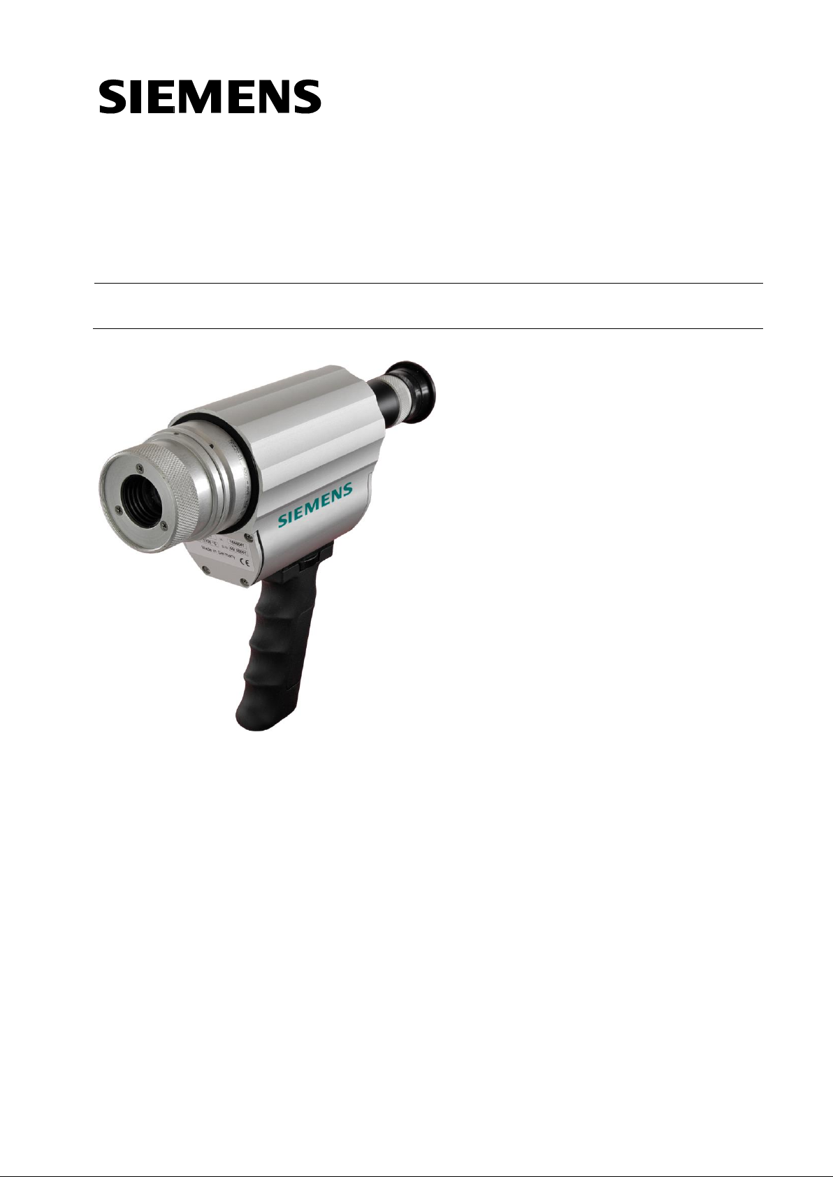
Two-colour Pyrometer
PT 14x
7MC3040-...
Operating Manual
03/2017
Page 2

Page 3

Two-colour Pyrometer PT
Ident.-Nr.: 106 7393
PT14x_si_en.doc
Stand: 21.03.2017
830 hm / 810 het
Page 4

Copyright prohibits the reproduction or distribution of this instruction
manual, including text, photographs or images contained herein, in whole
or in part, for any purpose whatsoever, without prior consent of the author. This applies to any form of mechanical or electronic reproduction as
well as to electronic transmission in any form through any
medium.
Please note:
Unless otherwise stated in this instruction manual, the instruments
described herein are subject to change without prior notice, particularly
modifications for the sake of technological advancement.
Siemens AG
Digital Factory
Customer Services DF&PD
DF CS SD OP ITM
Telefon +49 (911) 750-9600
Fax +49 (911) 750-9609
Email: sirent.industry@siemens.com
Office/Testing
Warehouse/Counter service
Breslauer Str. 5
Gundelfinger Str. 20
90766 Fürth
90451 Nürnberg
Germany
Germany
Page 5

s
Operating manual
Contents
1 Product Numbers Ardoptix PT .................................................. 1
2 Miscellaneous ............................................................................. 2
2.1 Informationen about this manual ........................................................ 2
2.2 Explanation of symbols ....................................................................... 2
2.3 Liability and Warranty ......................................................................... 2
2.4 Copyright ............................................................................................ 3
3 Safety .......................................................................................... 3
3.1 Intended use ....................................................................................... 3
3.2 User’s responsibility ................................ ................................ ............ 4
3.3 Electromagnetic Compatibility ............................................................ 4
4 Scope of delivery ........................................................................ 4
5 General Description ................................................................... 4
5.1 Intended Use ...................................................................................... 4
5.2 Operating Controls and Display .......................................................... 4
6 Charging the batteries ............................................................... 5
7 Preparing the pyrometer for measurements ............................ 6
7.1 General Information ............................................................................ 6
7.2 Diopter compensation ......................................................................... 6
7.3 Brightness control to protect the eye .................................................. 6
7.4 Focusing the pyrometer ...................................................................... 6
7.5 Align the pyrometers ........................................................................... 7
7.6 Performing a measurement ................................ ................................ 7
7.7 Automatic switch-off ........................................................................... 8
8 Setting parameters at the pyrometer (basic configuration) .... 8
9 Menu ............................................................................................ 9
9.1 Measurement two-colour/ratio mode configuration layer C001.......... 9
9.2 Configuration data acquisition configuration layer C010 ................... 10
9.3 General function configuration layer C011 ....................................... 10
9.4 Displayed temperature readings configuration layer C020 ............... 11
10 Setting the Emissivity Ratio (two-colour/ratio mode) ............ 11
11 Initializing emissivity ratio constants ..................................... 12
11.1 Define number of emissivity ratio constants in array ........................ 12
11.1.1 Store and assign emissivity ratio constants .................................. 12
11.2 Select the emissivity ratio constant ................................................... 12
12 Determining and Setting Emissivity (Spectral mode) ............ 13
13 Initializing emissivity factors (Spectral mode) ....................... 13
13.1 Define number of emissivity constants in array ................................ 13
13.1.1 Store and assign emissivity constants .......................................... 14
13.2 Select the emissivity constant ........................................................... 14
14 Further configuration ............................................................... 14
15 Configuration – signal conditioning ....................................... 14
15.1.1 Transmission factor (spectral mode) ............................................ 14
15.1.2 Background Temperature Compensation (Spectral mode) .......... 15
15.1.3 Temperature offset using linear interpolation ............................... 15
15.1.4 Smoothing function ................................ ................................ ....... 16
15.2 Min/Max memory .............................................................................. 17
15.2.1 Min/Max Memory .......................................................................... 17
Page 6

s
Operating manual
15.2.2 Double Maximum Memory with hold time ..................................... 17
15.2.3 Double Maximum Memory with hold time "Combined" ................. 18
15.2.4 Automatic Temperature Detection (ATD) ..................................... 18
16 Setting Parameters at the device ............................................ 22
16.1 Configuration layers ................................................................ .......... 22
16.1.1 Temperature measurement using two-colour/ratio mode ............. 23
16.1.2 Temperature measurement lambda 1 .......................................... 24
16.1.3 Temperature measurement lambda 2 .......................................... 25
16.1.4 Configuration I/O .......................................................................... 27
16.1.5 General Functions ........................................................................ 28
16.1.6 Displayed temperature readings ................................................... 29
17 Software CellaView .................................................................. 29
18 PC Interface .............................................................................. 29
19 Remote configuration .............................................................. 30
19.1 Main Menu ........................................................................................ 31
19.2 View Current Configuration............................................................... 31
19.3 Submenus ........................................................................................ 32
19.3.1 Configure two-colour/ratio mode .................................................. 32
19.3.2 Lambda 1 ..................................................................................... 32
19.3.3 Lambda 2 ..................................................................................... 33
19.3.4 Quick access to emissivity / signal smoothing / operating mode .. 33
19.3.5 I/O Signal Configuration ............................................................... 33
19.3.6 Automatic temperature data output .............................................. 35
19.4 User Recalibration ............................................................................ 36
20 Maintenance ............................................................................. 38
20.1 Cleaning the pyrometer lens/protective glass ................................... 38
21 Accessories .............................................................................. 39
21.1 Supplementary lens .......................................................................... 39
22 Theory of Non-Contact Temperature Measurements ............ 40
22.1 Emissivity .......................................................................................... 40
22.2 Temperature measurement using spectral mode ............................. 41
22.3 Temperature measurement using two-colour/ratio mode ................. 41
22.4 Emissivity Coefficient Table – Spectral Mode ................................... 42
23 General technical data ............................................................. 43
24 Technical Data PT 140 (650 – 1700 °C) .................................... 43
24.1 Field of View Diagrams PT 140 (650 – 1700 °C) .............................. 43
25 Technical Data PT 140 (750 – 2400 °C) .................................... 45
25.1 Field of View Diagrams PT 140 (750 – 2400 °C) .............................. 45
26 Technical Data PT 143 (650 – 1700 °C) .................................... 46
26.1 Field of View Diagrams PT 143 (650 - 1700°C) ................................ 46
27 Technische Daten PT 143 (MB 750 - 2400°C).......................... 47
27.1 Field of View Diagrams PT 143 (MB 750 - 2400°C) ......................... 47
29 Dimensions ............................................................................... 48
30 Shipping, Packaging and Disposal ......................................... 49
30.1 Inspecting your shipment .................................................................. 49
30.2 Packaging ......................................................................................... 49
30.3 Disposal of used apparatus .............................................................. 49
31 Copyright .................................................................................. 50
Page 7

s
Operating manual
32 Default settings ........................................................................ 51
32.1 Temperature measurement (Configuration layer: C001)............. 51
32.2 Temperature measurement Lambda 1 /2(Configuration layer: C002) .. 52
32.3 Temperature measurement Lambda 2(Configuration layer: C003) ...... 53
32.4 General Functions (Configuration layer: C010) ........................... 53
32.5 General Functions (Configuration layer: C011) ........................... 54
Page 8

s
Operating manual
Page 9

s
Operating manual
1
1 Product Numbers Ardoptix PT
Pyrometer
Temperarute range
Product number
Ardoptix PT 140 AF1
MB: 650-1700 °C, D=80:1 (St.-Optic)
7MC3091-1AB40
Ardoptix PT 140 AF4
MB: 750-2400 °C, D=150:1 (St.-Optic)
7MC3091-1AB20
Ardoptix PT 143 AF1
MB: 650-1700 °C, DV=230:1, DH=45:1
(St.-Optic)
7MC3091-1AB43
Ardoptix PT 143 AF4
MB: 750-2400 °C, DV=350:1, DH=50:1
(St.-Otic)
7MC3091-1AE43
Page 10

s
Operating manual
2
2 Miscellaneous
2.1 Informationen about this manual
The Operating Manual shall enable the user to properly install the
pyrometer and those accessories which are necessary.
Before starting installation, be sure to read and understand this entire
manual, in particular the chapter on safety! The instructions contained in
this manual, especially those concerning safety, as well as site-specific
regulations governing UV radiation must be complied with at all times!
2.2 Explanation of symbols
Important safety-related references in this manual are marked with a
symbol.
CAUTION!
This symbol indicates important information which, if neglected, might
result in pyrometer damage, malfunction or breakdown.
PLEASE NOTE !
This symbol points out guidelines which should be heeded for efficient
and trouble-free operation.
2.3 Liability and Warranty
All information compiled in this manual is in accordance with applicable
regulations. The statements made are based on state-of-the-art technology and reflect our extensive knowledge and many years of experience.
PLEASE NOTE !
Always carefully read this Operating Manual before beginning any
work on or with the instrument, especially prior to installation and
initial setup! The Manufacturer shall not be held liable for any
damages or malfunctions arising from a disregard of the warnings
and instructions contained herein.
This Operating Manual must be retained for future use. Please ensure
that all persons who wish to operate the instrument have access to this
manual.
Page 11

s
Operating manual
3
2.4 Copyright
This Operating Manual should be treated as confidential. It is solely intended for use by persons involved with the instrument. This manual may
not be made available to a third party without prior Manufacturer’s con-
sent. Please contact the Manufacturer if the need should arise.
PLEASE NOTE !
The data, texts, charts, drawings, images or other representations contained in this manual are copyright-protected and furthermore, subject to
intellectual property rights. Violators will be prosecuted. Unauthorised
use and copyright infringement will be subject to penalty by law.
Reproductions of any kind, in whole or in part, as well as the exploitation
or disclosure of this manual’s content without the explicit written approval
of the Manufacturer are expressly prohibited by law. Violations shall be
subject to compensation claims by the Manufacturer. The right to claim
additional indemnities remains reserved.
3 Safety
This chapter outlines all important safety aspects to be considered for
optimum employee protection and to ensure safe and reliable operations.
3.1 Intended use
The pyrometer is solely intended for non-contact measurement of temperatures as described in this manual. Any other use is not intended.
Operational safety can only be ensured when the instrument is used for
its intended purpose.
CAUTION !
It is prohibited to use the pyrometer for any other purpose beyond what
is specified in this manual. Using the instrument in any other manner will
be considered as improper.
The Manufacturer/Authorised Agent shall not be held liable for any damages or loss resulting from such unintended or improper use; in this case
the risk is solely borne by the user.
Page 12

s
Operating manual
4
3.2 User’s responsibility
The pyrometer may only be used when it is in perfect working condition.
3.3 Electromagnetic Compatibility
The devices comply with the essential safety requirements of the Electromagnetic Compatibility Directive 2014/30/EU (EMC Act).
4 Scope of delivery
Make sure that all of the following components have been included with
your shipment:
Pyrometer
Carrying case
Power supply
Calibration certificate
Software CellaView (Download Version)
USB cable
5 General Description
5.1 Intended Use
The Ardoptix PT series provides efficient pyrometers for non-contact
temperature measurements.
The two-colour pyrometer Ardoptix PT 14x measures the intensity of infrared radiation at two different wavelengths. The ratio of these two intensities is proportional to the temperature. The Ardoptix PT 14x is used
for temperature measurement from 650 °C to 2400 °C. These instruments serve a broad range of applications which include the iron and
steel producing industry as well as the metal, glass, cement and chemical industries.
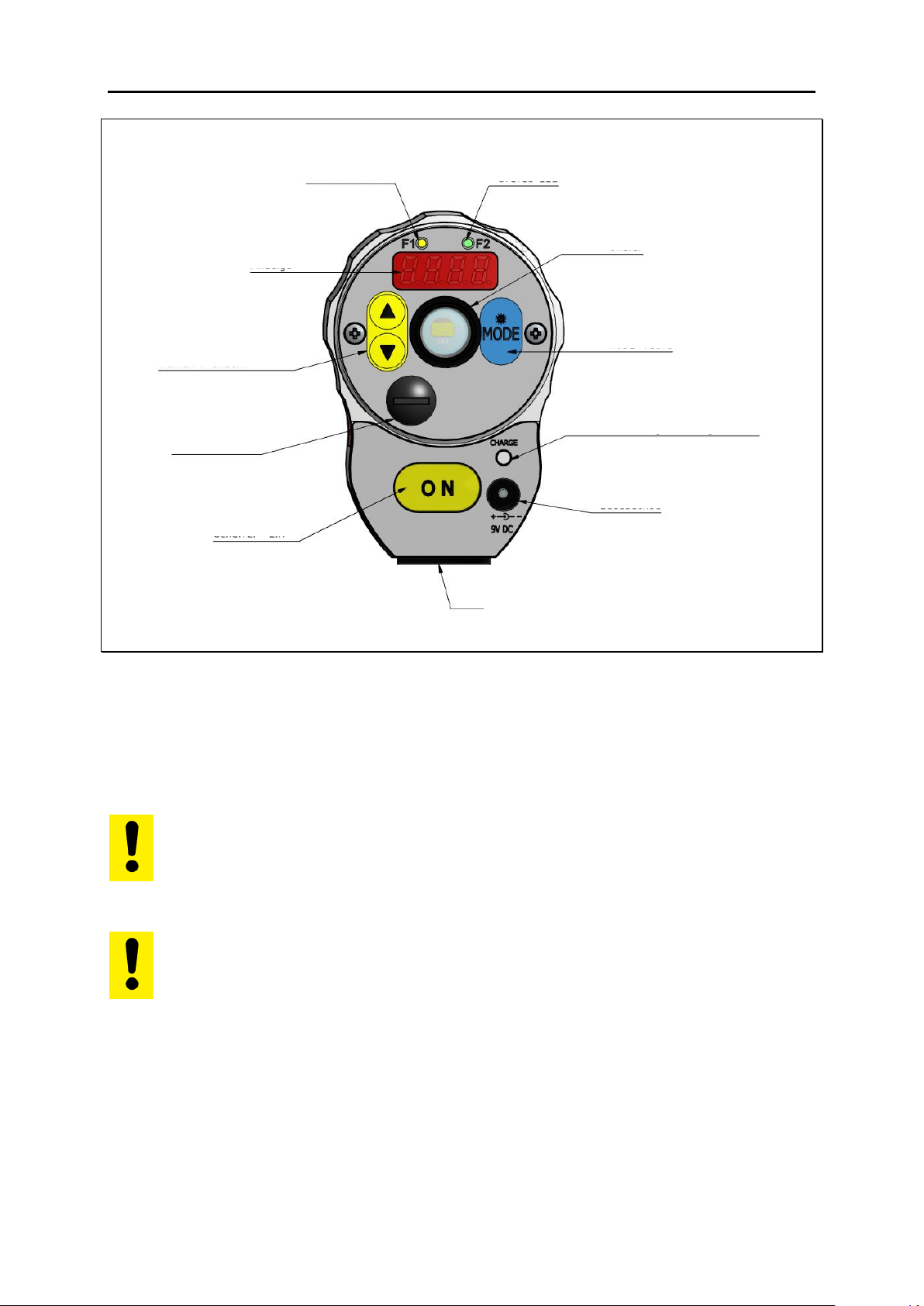
5.2 Operating Controls and Display
The rear panel of the Ardoptix has a 4-digit display and 4 push-buttons.
The display normally indicates the currently measured temperature. During configuration (using the push-buttons), the display will show the parameter you are setting. Whenever the display shows a parameter, the
F1 Parameter LED (yellow) will light up. During a running measurement,
the F2 Status LED (green) will light up.
Page 13
s
Operating manual
5
6 Charging the batteries
Connect the battery charging socket of the Ardoptix to the provided power supply (9 V DC). The charge indicator lights as long as the batteries
are being charged. A complete charging cycle takes approx. 15 hours.
Parameter LED
Status LED
Ocular
Mode key
Charge indicator
Charging socket
¼“ Tripod thread
Switch „ON“
USB connection
Parameter
select / change
Display
Only use the power supply which comes with the pyrometer. Do not use any other power supply as this may cause
irreparable damage to the device.
The charger is only for charging the battery.
The rechargeable battery is only charged when the pyrometer is switched off.
Page 14
s
Operating manual
6
7 Preparing the pyrometer for measurements
7.1 General Information
The pyrometer’s field of view must remain unobstructed. Any obstruction
may lead to measurement errors.
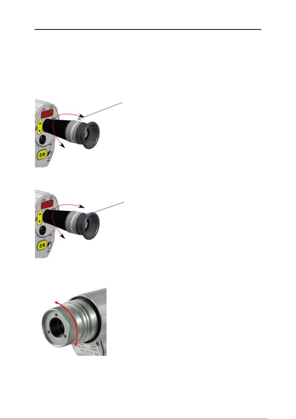
7.2 Diopter compensation
7.3 Brightness control to protect the eye
7.4 Focusing the pyrometer
To ensure precise temperature measurement, the pyrometer
must be correctly focused on the target object
The pyrometer offers diopter compensation to adjust the sighting device to the
user’s vision. Turn the ring until you see
a sharp image of the target spot indication in the viewfinder.
Instruments with a measuring range of
> 2000 °C are equipped with a polarisation
filter to control brightness and protect the
user’s eye.
The pyrometer is equipped with focusable
optics. Turn the lens until the target object
and the target marker (distinctly marked in
the viewfinder) both appear in sharp focus
simultaneously
Page 15

s
Operating manual
7
7.5 Align the pyrometers
Direct the Ardoptix to the object to be measured. The target marker in
the through-the-lens sighting device indicates the size of the target. (see
technical data/ course of target). When measuring with a two-colour pyrometer, the object to be measured is not required to fill the complete
measurement area. The integrated traffic light function in the viewfinder
signals an inadmissible partial illumination and the measurement is
stopped.
7.6 Performing a measurement
Press the ON button to switch on the device. If necessary adjust the ratio
correction. Focus the target marker at the diopter correction switch and
adjust the pyrometer lens to the correct measuring distance.
Measurement is in progress as long as you press the ON button. The
temperature (depending on the configured mode) is displayed on the
rear panel when you release the ON button. As an option, the measurement readings can be transmitted via interface.
1) Traffic light indicates
2) Measurement area
3) Target object
2
3
1
The amount of thermal radiation emitted from an object depends on the specific radiation properties of the material and its
surface. Non-contact temperature measurement requires that
you determine the material constant (emissivity) of the target
object prior to first-time use
Page 16
s
Operating manual
8
7.7 Automatic switch-off
In the default setting, the Ardoptix switches off automatically after 2
minutes if none of the control keys are pressed. Automatic switch-off can
be configured from 1 – 60 minutes. The Ardoptix measures continuously
when it is in "automatic disconnection deactivated" mode.
8 Setting parameters at the pyrometer (basic configura-
tion)
Use the buttons ▲▼ and the „MODE" button on the rear panel to access
and configure parameters. With these buttons you can view and adjust
all settings required for operating the pyrometer.
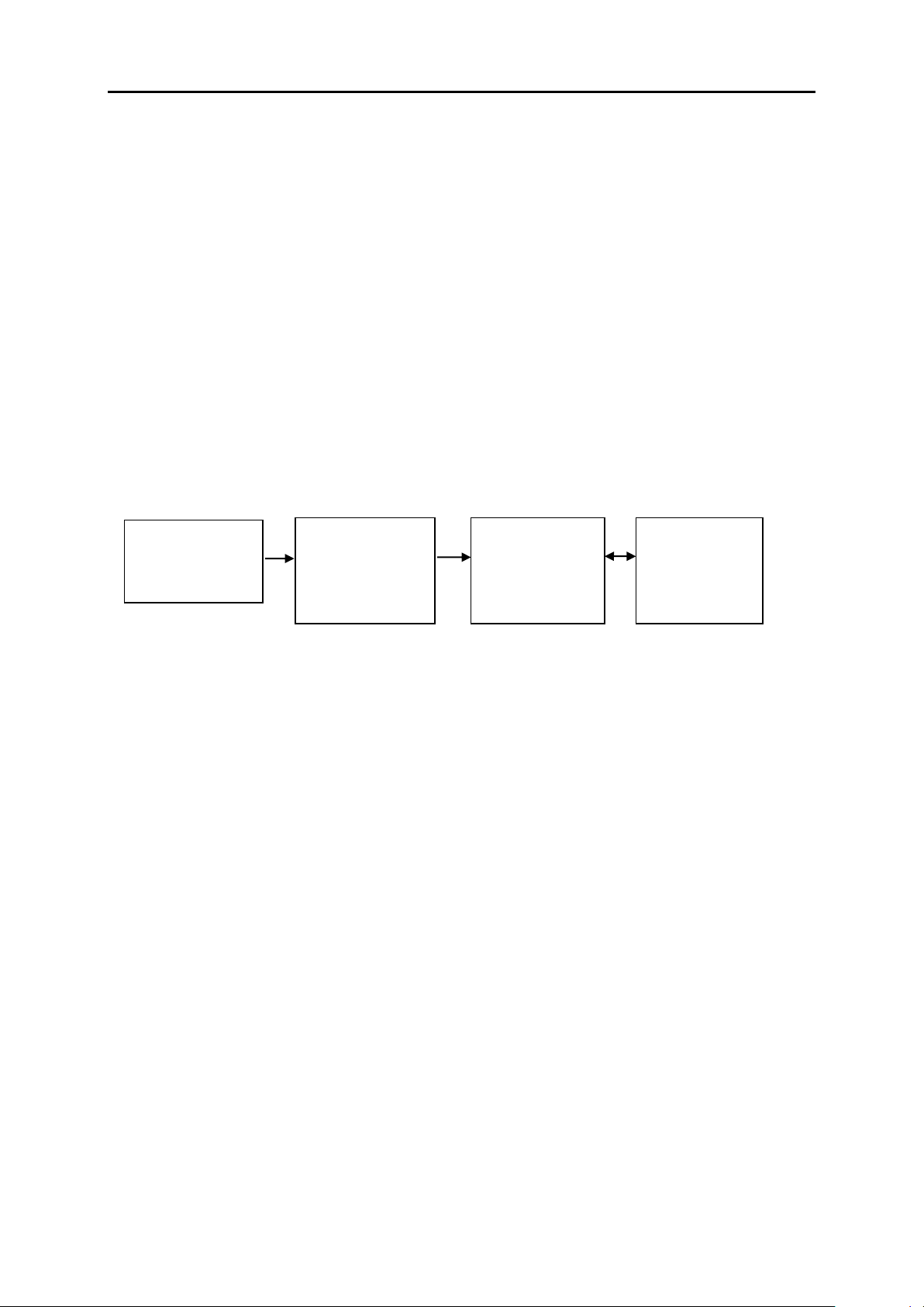
Menu structure:
1. Press the MODE button while in normal operating mode to switch
to "configuration layer" mode.
2. Use ▲▼ to select the configuration layer for the parameter you
wish to set.
3. Press MODE to confirm. Press ▲▼ to select the particular parameter.
4. Press MODE to confirm. Press ▲▼ to adjust the parameter value.
5. Press MODE again to end. Press ▲▼ to select END.
Whenever a control key has not been pressed within 30 seconds, the pyrometer will automatically return to normal operating mode. The modified
value is applied.
Normal
operating mode
(temperature)
Select
config. layer
C000-
C999
Select
parameter
EPS1
Adjust
parameter
99.9
MOD
MOD
MOD
▲▼
▲▼
▲▼
Key lock may have been activated at the terminal. When selecting the configuration layer you will be prompted to enter an access code with
P000
. To obtain full access to parameter set-
tings, enter
P100
otherwise you will only be able to view pa-
rameters but not change them.
Page 17
s
Operating manual
9
9 Menu
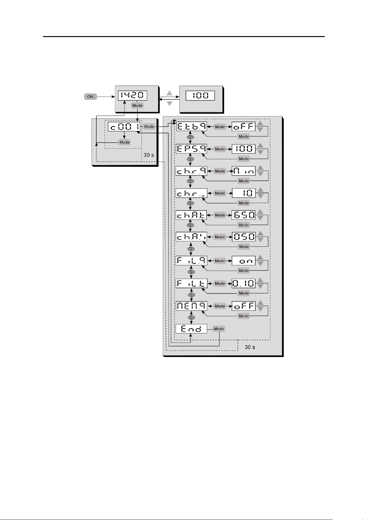
9.1 Measurement two-colour/ratio mode configuration layer
C001
In the default configuration, certain parameter settings will be
hidden. If required, you can have them shown
Page 18
s
Operating manual
10
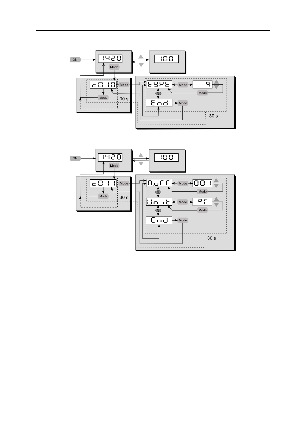
9.2 Configuration data acquisition configuration layer C010
9.3 General function configuration layer C011
Page 19
s
Operating manual
11
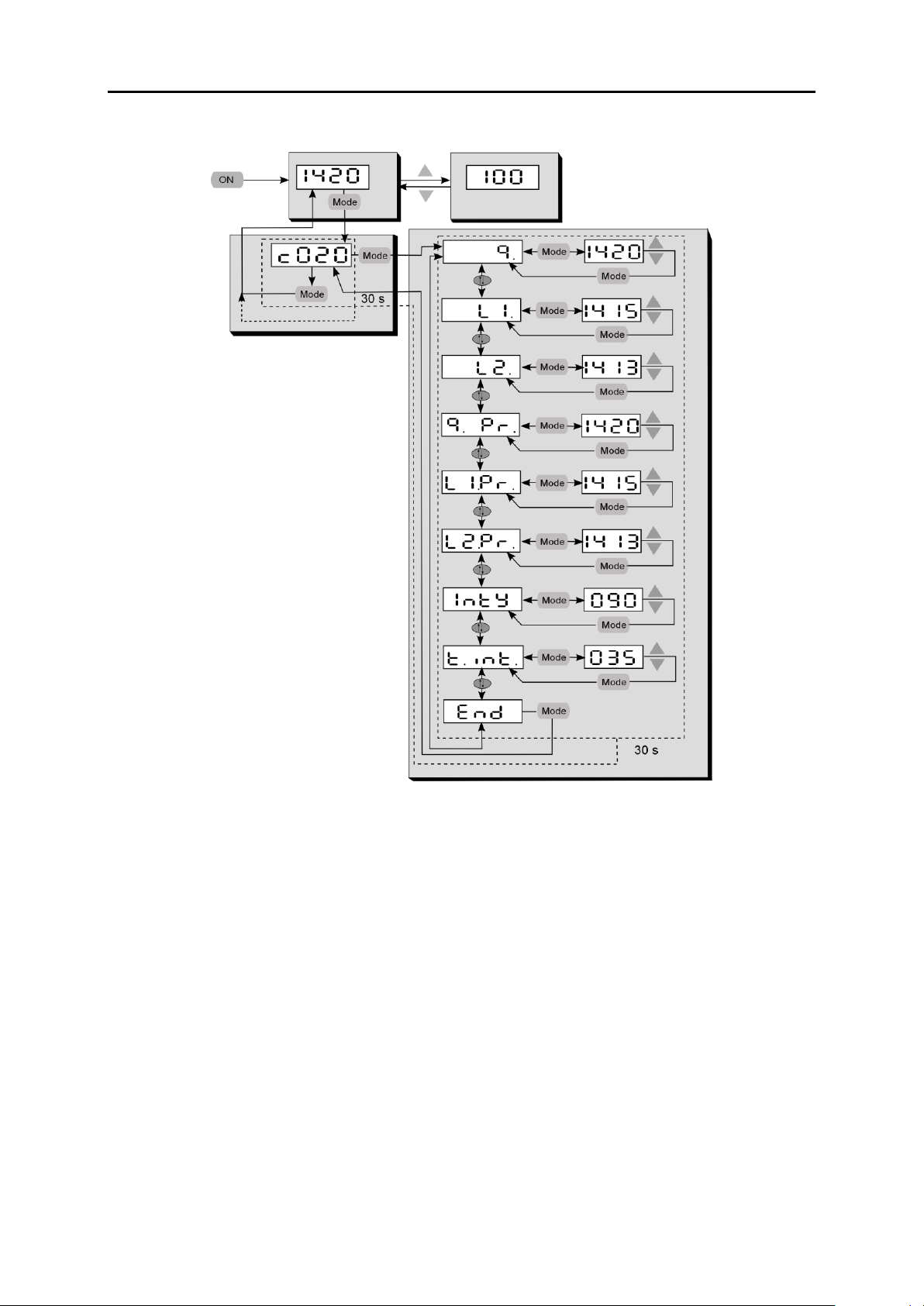
9.4 Displayed temperature readings configuration layer C020
10 Setting the Emissivity Ratio (two-colour/ratio mode)
When the radiation properties of the target object’s surface (emissivity)
differ at two different wavelengths, or when interferences in the field of
view—such as dust or steam—do not weaken the signal to the same degree at each wavelength, the pyrometer can be adjusted by setting the
ratio of these two emissivity coefficients.
During normal operating mode, the emissivity ratio can
be set at the pyrometer using the ▲▼ buttons. When
simultaneously pressing the MODE key, the display
shows the current measuring temperature while the
emissivity ratio coefficient continues to be adjusted in the
background. This is an easy way to determine the emissivity ratio when the object temperature is known. The
modified values are directly adopted.
Page 20

s
Operating manual
12
11 Initializing emissivity ratio constants
The Ardoptix lets you store up to 10 emissivity ratio factors. Before you
perform a new measurement, simply use the ▲▼ control keys to select
your preconfigured emissivity factor. When you select a stored emissivity
ratio factor, the display will briefly show the preconfigured factor for that
emissivity ratio factor.
11.1 Define number of emissivity ratio constants in array
Before you configure the pyrometer with emissivity ratio factors, you
must define the size/length of the array. This is the number of emissivity
ratio you would like the array to contain (10 maximum). Using parameter
E.TB.Q, enter the total number.
Measurement two-colour/ratio mode configuration layer C001
Parameter
Function
Explanation
E.TB.Q
Enter desired number
of elements in array
If E.TB.1 = OFF, then use
▲▼ keys to manually set emissivity ratio
11.1.1 Store and assign emissivity ratio constants
Next, assign a value to each emissivity ratio constant in the index.
Measurement two-colour/ratio mode configuration layer C001
Parameter
Function
Explanation
E. 01
Emissivity ratio
Memory position 1
z. B. 100.5 %
E. 02
Emissivity ratio
Memory position 2
z. B. 101 %
E. 03
Emissivity ratio
Memory position 3
z. B. 101.5 %
11.2 Select the emissivity ratio constant
The memory position can optionally be set using the menu.
Once you have configured the emissivity ratio parameter,
the pyrometer will maintain this specific setting. The pyrometer will always operate with this value unless you
change the setting.
Page 21

s
Operating manual
13
Measurement two-colour/ratio mode configuration layer C001
Parameter
Function
Explanation
E.IDX
Memory position
Shows current selected emissivity ratio constant, e.g. E. 02
12 Determining and Setting Emissivity (Spectral mode)
In pyrometry, the specific radiation characteristics of the measured object
will influence the generated temperature data. In order to produce accurate and reliable temperature readings, the pyrometer must be configured according to the specific material constant (emissivity).
In spectral operation mode, emissivity can be set at the pyrometer using
the ▲▼ buttons. This changed setting will apply immediately to the current temperature measurement
13 Initializing emissivity factors (Spectral mode)
The Ardoptix lets you store up to 10 emissivity factors for lambda 1 and
lambda 2. Before you perform a new measurement, simply use the ▲▼
control keys to select your preconfigured emissivity factor. When you select a stored emissivity factor, the display will briefly show the preconfigured factor for that emissivity factor.
13.1 Define number of emissivity constants in array
Before you configure the pyrometer with emissivity factors, you must define the size/length of the array. This is the number of material constants
you would like the array to contain (10 maximum). Using parameter
E.TB.1/ E.TB.2, enter the total number.
Once you have configured the emissivity parameter, the
pyrometer will maintain this specific setting. The pyrometer will always operate with this value unless you change
the setting.
To determine the correct setting of the emissivity of a comparative measurement is carried out by a contact measurement. In
order to minimize measurement differences between the two
different physical measuring methods, the comparison measurement is almost the same time and performs at the same
measuring point as possible.
Page 22

s
Operating manual
14
Temperature measurement lambda 1 (Configuration layer: C002)
Parameter
Function
Explanation
E.TB.1
Enter desired number
of elements in array
If E.TB.1 = OFF, then use
▲▼ keys to manually set emissivity
13.1.1 Store and assign emissivity constants
Next, assign a value to each material constant in the index (E. 01, E.
02 etc.).
Temperature measurement lambda 1 (Configuration layer: C002)
Parameter
Function
Explanation
E. 01
Emissivity
Memory position 1
z. B. 75 %
E. 02
Emissivity
Memory position 2
z. B. 60 %
E. 03
Emissivity
Memory position 3
z. B. 50 %
13.2 Select the emissivity constant
The memory position can optionally be set using the menu.
Temperature measurement lambda 1 (Configuration layer: C002)
Parameter
Function
Explanation
E.IDX
Memory position
Shows current selected emissivity constant,
e.g. E. 02
14 Further configuration
15 Configuration – signal conditioning
15.1.1 Transmission factor (spectral mode)
The pyrometer has to be adjusted for the transmission properties of any
supplementary lens and/or protective window screwed onto the pyrometer. Set the pyrometer for the specific transmission factor (a percentage
value) which is indicated either in the product’s data sheet or on the lens
itself. This is parameter TAU.1 and can be accessed at configuration
layer C002/C003. If you are not using any auxiliary lens or protective
window, set the parameter to 100.0.
Parameters for lambda 2 are identical to lambda 1. See Chapter 16.1.3
Page 23

s
Operating manual
15
15.1.2 Background Temperature Compensation (Spectral mode)
Thermal radiation reflected from the surrounding will require that you
make an additional correction when the reflected radiation is strong
compared to the natural radiation of the target. This applies to object surfaces which have very low emissivity or when the temperature of the object is lower than the temperature of its surroundings.
The background radiation reflected from the object consists of the following factors:
Background temperature
Background size
The capability of the background material to reflect infrared radia-
tion
To ensure that the measurement is not distorted and that the temperature readings are completely accurate, you should activate "background
temperature compensation" (switch on C002 or C003 / BAC.1).
Now enter the temperature value of the ambient source of radiation
(BAC.T) and its influence as a percentage (BAC.%). The influence in
percent stands for the size and the capability of the material to emit infrared radiation. You will have to determine these variables first.
15.1.3 Temperature offset using linear interpolation
When necessary, Ardoptix PT allows you to program an offset for the
temperature reading reported. The offset correction can be configured
Source of extraneous radiation
Example: furnace 950 °C
Target object TO = 900 °C
Emissivity e < 1
Reflection s > 0
Furnace radiation T
Back
= 950 °C
Page 24

s
Operating manual
16
individually with a minimum of 2 and a maximum of 10 interpolating
points (X/Y nodes). This information is stored in a user-defined temperature-indexed lookup table and used for signal conditioning. For values
lower than the 1st node and higher than the last node, the first and last
linear segments are extrapolated. Enter the nodes in ascending order.
Use the rear panel display to access this function via C001 / LIN.1.
15.1.4 Smoothing function
When the target object’s temperature is erratic, it makes sense to
smooth these temperature fluctuations in order to stabilize the signal.
The greater the time constant t
98,
(user-definable), the lower the effect of
these fluctuations on the yielded temperature reading. The pyrometer’s
response time is proportional to the time constant. Set signal smoothing
via parameter C001 / FIL.Q.
analogue
output
signal
time
output signal without
smoothing
output signal with
smoothing
X4
X3
X1
X2
Y1
Y2
Y3
Y4
Temperature before offset
Temperature after offset
Page 25

s
Operating manual
17
15.2 Min/Max memory
The pyrometer features a data memory to store minimum and maximum
(peak) temperature readings. This feature can be configured in one of
the following modes:
Memory off
Store minimum value (single)
Store maximum value (single)
Store double max. value for cyclical processes
ATD function (Only available in pyrometer with ATD function)
15.2.1 Min/Max Memory
In this mode—also called peak picker—the pyrometer determines the
highest or lowest temperature reading and keeps the temperature reading. The value is stored until you press the ON button again. Additionally,
you can define the smoothing filter setting.
15.2.2 Double Maximum Memory with hold time
In this operating mode the pyrometer continuously detects the maximum
temperature reading. This value is stored for the duration of the configured hold time and is displayed on the rear panel. In mid-sequence – after 50% lapse of the hold time – a second internal peak picker starts.
When the hold time has expired without finding a new max value, the
output signal decreases to the value of the second peak temperature (if it
turned out being lower than the first peak).
This memory mode serves to detect the maximum temperature of objects moving periodically past the pyrometer lens. The temperature reading is kept for the duration of the configured holding time when the pyrometer does not detect any hot object. The holding time should be configured to approximately 1.5 times as long as the cycle of the moving targets. This ensures that a temperature measurement gap is avoided and
temperature changes are detected quickly.
Page 26

s
Operating manual
18
target object in the pyrometer’s field of view
holdtime
time
temp. reading with double max. buffer
temp. measurement without double max. buffer
15.2.3 Double Maximum Memory with hold time "Combined"
The function of the double maximum memory "combined" is similar to
that of the double maximum memory. However, the hold time starts
when the spectral temperature is at its highest point. Displayed is the
corresponding two-colour temperature. If the spectral temperature decreases during the hold time, the corresponding two-colour temperature
is only displayed when the hold time has elapsed. If the spectral temperature rises during the hold time, the corresponding two-colour temperature is directly displayed.
15.2.4 Automatic Temperature Detection (ATD)
The ATD function allows a very easy and fully automatic capture of the
temperature. As soon as the pyrometer is switched on and aimed at a
hot object, the measurement starts automatically. The threshold value to
detect a hot object is adjustable. Depending on the configuration, the
measurement ends either after a selectable period or when there is no
longer a hot object in the pyrometer's measurement area. At the end of
the measurement the captured value is displayed until a new measuring
object is detected. To eliminate unrealistic measurement differences, it is
possible to check the determined measured value for plausibility in relation to the previous measured value and to filter it out. The new measured value can also be averaged with a weighting factor to eliminate
large jumps between the measured values.
Page 27

s
Operating manual
19
Threshold limits
The start of a measuring cycle is determined automatically and is dependent on the following variables:
Parameter
Function
Limit 1 (LI. 1)
Before beginning the measurement, the
temperature reading must have been lower
than Limit 1 at least once.
If Auto reset is activated (A.RST= ON),
Limit 1 will be ignored
Limit 2 (LI. 2)
Limit 2 must be exceeded at least for the
duration of the time delay (T.DEL).
Time Delay (T.DEL):
See Limit 2
When the conditions are fulfilled, the sampling time can begin (T.ACT).
Page 28

s
Operating manual
20
Parameter
Function
Sampling time
(T.ACT)
During the sampling time the temperature is
detected and stored as a temperature value.
Display and output of temperature reading [ANO]
The parameter ANO (normal display mode) defines which temperature
value is saved during sampling.
Parameter
Function
Display mode (ANO)
„T=0“ displays the lower temperature range
limit during the measurement.
„T.HLD“ indicates the previous tempera-
ture reading during the current measurement.
The green status LED indicates that a measurement is currently in process.
Average weighting [F-PR] Plausibility check
When the sampling time has ended, an average value is calculated for
recorded measuring cycles. The temperature reading is weighted with
the previously saved average value and added.
Parameter
Function
Weighted average
(F-PR)
Factor for average weighting. If you enter
100%, averaging will be off.
The smaller you set the F-PR factor, the stronger the weighting will be.
When the averaging function is activated (F-PR <100%) a plausibility
check will be performed. The difference in temperature between the current reading and the previously stored average is determined. If this deviation is greater than the plausibility threshold TSP, the transmitted data will be „0“ and the average value will remain unchanged.
Enter the upper threshold and lower threshold for the permissible deviation separately.
The parameter T.ACT= 0 automatically recognizes the
end of the discontinuous process (measured temperature
< L2). The pyrometer then shows "Auto" instead of the time
under parameter T.ACT.
Page 29

s
Operating manual
21
Parameter
Function
Plausibility (TSP_)
Permitted temperature difference for a valid
measurement when the new value is lower
than the stored measured value.
Plausibility (TSP~)
Permitted temperature difference for a valid
measurement when the new value is higher
than the stored measured value.
If a measuring cycle does not start during the period T.OUT the saved
average will be deleted and reinitialized when the next cycle begins.
Parameter
Function
Timeout
(T.OUT)
Time cycle for deleting average value (in
minutes)
At the end of the measuring cycle the pyrometer displays the averaged
temperature value (or the invalid reading „----“ ).
Cut-off interval [T.DIS]
A cut-off interval (time lag) begins after the measuring time has ended.
This cut-off interval must expire before the next measurement can start
with the cycle starting conditions described above.
Parameter
Function
Cut-off interval
(T.DIS)
The interval between one completed sampling and the start of a new sampling.
Timeout [T.OUT]
If a measuring cycle does not start during the period T.OUT, the saved
average will be deleted and reinitialized when the next cycle begins.
Parameter
Function
Timeout (T.OUT):
Time out for average function (in minutes)
Autoreset Function [A.RST]
Activate auto reset for the ATD function to run cyclically. Limit 1 will then
be ignored.
Normally, for a new measuring cycle to start, the detected temperature
must have dropped below Limit 1. If, however, you wish to measure a
Page 30

s
Operating manual
22
continuous process (continuous material flow), you must activate Auto
Reset. Limit 1 will then be ignored. Sampling will continue (restarting automatically and producing temperature readings cyclically) as long as
Limit 2 is exceeded for the time period defined by T.DEL.
Parameter
Function
Autoreset (A.RST):
Autoreset on/off
Parameter Set Li2 check on tAct [CH.L.2]
When this parameter is set to ON (CH.L.2=on), the detected temperature must exceed Limit 2 during the entire measuring time (TACT) in
order for the pyrometer to generate a valid temperature reading. The
measurement is discarded when the value falls below Limit 2.
The display shows „----“
Parameter
Function
Set Li2 check on tAct (CH.L.2)
on/off
16 Setting Parameters at the device
In addition to the configuration possibilities described, many parameters
can be adjusted at the rear panel using push buttons. These settings can
be accessed via configuration layers.
16.1 Configuration layers
The configuration layers are structured as follows:
C001 Temperature measurement two-colour/ratio mode
C002 Temperature measurement lambda 1
C003 Temperature measurement lambda 2
C010 I/O configuration (LED / Buzzer)
C011 General function
C020 Display temperature readings
The following chart lists all parameters. In the factory default configuration, certain parameters and configuration layers will not be accessible
by control key. This is meant to simplify pyrometer operation for the user.
These parameters are indicated by. If required, remote access to these
parameters can be enabled via PC interface or at configuration layer
C011. Open the user calibration menu (Menu mode: Full).
Some parameter settings will be hidden if their basic function has been
deactivated. For example, you will not be able to adjust the smoothing
Page 31

s
Operating manual
23
time of the filter if the filter has been turned off or switched to automatic
mode.
16.1.1 Temperature measurement using two-colour/ratio mode
(Configuration layer: C001)
Parameter
Function
Explanation
E.TB.Q
Array size
Use array with 1-10 entries or enter material
constant directly into the pyrometer
EPS.Q
Ratio correction
E.IDX
Memory position
Customize the array; assign a value to each
of the ratio correction in the array. Possible
indexes depend on the size of the array
E. 01
Assign ratio correction
constants
Customize the array; assign a value to each
of the ratio correction in the array. Possible
indexes depend on the size of the array
CH.R.Q
Plausibility check ratio
mode
OFF off
MIN deactivation when below limit
MI.MA. deactivation when below or above limit
CH.R._
Relative limit min.
Relative lower limit [%] , two-colour temp.
reading invalid (signal intensity)
CH.R.~
Relative limit max.
Relative upper limit [%] , two-colour temp.
reading invalid (signal intensity)
CH.A.T
Absolute min. temp.
Absolute lower limit, two-colour temp. reading
invalid
CH.A.%
Absolute minimum
Emissivity
Absolute lower limit [%], two-colour temp.
reading invalid
LIN.Q
Temperature offset
using linear
OFF off
2-10 number of nodes used
L. X1
node x 1 - 10
Signal input (initial value) node n
L. Y1
node y 1 - 10
Signal output (resulting value) node n
FIL.Q
Smoothing filter
OFF
ON
FIL.T
Smoothing time
Time in seconds t98
MEM.Q
Min/Max memory
OFF off
MIN lowest (min.)temperature, single
MAX highest (max.) temperature, single
DBL.M double maximum
DIS.M ATD function
MEM.T
Hold time for Min/Max
Hold time in sec.
FIL.M
Smoothing filter for
min/max*
OFF OFF
ON ON
FIL.T
Smoothing time*
Time t98 in sec.
T.DEL
time delay **
For ATD function, see Chap. 15.2.4
T.ACT
Sampling time **
For ATD function, see Chap. 15.2.4
T.DIS
cut-off interval **
For ATD function, see Chap. 15.2.4
T.OUT
Timeout**
For ATD function, see Chap. 15.2.4
LI. 1
Limit 1**
For ATD function, see Chap. 15.2.4
LI. 2
Limit 2**
For ATD function, see Chap. 15.2.4
F-PR
Average weighting **
For ATD function, see Chap. 15.2.4
TSP~
Plausibility
threshold **
For ATD function, see Chap. 15.2.4
Page 32

s
Operating manual
24
TSP~
Plausibility
threshold **
For ATD function, see Chap. 15.2.4
MEM.T
Hold time for Min/Max
Hold time in sec.
FIL.M
Smoothing filter for
min/max*
OFF OFF
ON ON
FIL.T
Smoothing time*
Time t98 in sec.
END
End
Exit menu
*
Only available with Min/Max and Double Max modes
**
Only available with ATD function
16.1.2 Temperature measurement lambda 1
(Configuration layer: C002)
In the factory default configuration, all parameter settings for digital inputs and outputs will be hidden.
Parameter
Function
Explanation
E.TB.1
Array size
Use array with 1-10 entries or enter material
constant directly into the pyrometer
EPS.1
Emissivity factor L1
Enter material constant directly into the pyrometer
E.IDX
Memory position
Choose an entry from the material constants
array
E. 01
Assign material
constants
Customize the array; assign a value to each
of the material constants in the array. Possible
indexes depend on the size of the array
TAU.1
Transmittance factor
L1
BAC.1
Ambient temperature
compensation
BAC.T
Temp. of ambient
source of radiation
BAC.%
Influence of ambient
IR radiation
The reflected thermal radiation from the surroundings as a portion of the total IR radiation
collected by the sensor in %
LIN.1
Temperature offset
using linear
OFF off
2-10 number of nodes used
L. X1
node x 1 - 10
Signal input (initial value) node n
L. Y1
node y 1 - 10
Signal output (resulting value) node n
FIL.1
Smoothing filter
OFF smoothing not activated
ON simple smoothing
FIL.T
Smoothing time
time t98 in sec for simple smoothing
MEM.1
Min/Max memory
OFF off
MIN lowest (min.)temperature, single
MAX highest (max.) temperature, single
DBL.M double maximum
DIS.M ATD function
MEM.T
Hold time for Min/Max
Hold time in sec.
FIL.M
Smoothing filter for
min/max*
OFF OFF
ON ON
FIL.T
Smoothing time*
Time t98 in sec.
Page 33

s
Operating manual
25
T.DEL
time delay **
For ATD function, see Chap. 15.2.4
T.ACT
Sampling time **
For ATD function, see Chap. 15.2.4
T.DIS
cut-off interval **
For ATD function, see Chap. 15.2.4
T.OUT
Timeout**
For ATD function, see Chap. 15.2.4
LI. 1
Limit 1**
For ATD function, see Chap. 15.2.4
LI. 2
Limit 2**
For ATD function, see Chap. 15.2.4
F-PR
Average weighting **
For ATD function, see Chap. 15.2.4
TSP~
Plausibility
threshold **
For ATD function, see Chap. 15.2.4
TSP~
Plausibility
threshold **
For ATD function, see Chap. 15.2.4
ANO
Mode of display **
T=0 show lower limit of temp. range dur-
ing running measurement
T.HLD Hold previous temp. reading during
running measurement
A.RST
Auto reset**
For ATD function, see Chap. 15.2.4
CH.L.2
Set Li2 check on tAct**
For ATD function, see Chap. 15.2.4
END
End
Exit menu
*
Only available with Min/Max and Double Max modes
**
Only available with ATD function
16.1.3 Temperature measurement lambda 2
(Configuration layer: C003)
By default, some parameters are suppressed to facilitate operation.
Parameter
Function
Explanation
E.TB.
Array size
Use array with 1-10 entries or enter material
constant directly into the pyrometer
EPS.2
Emissivity factor L2
Enter material constant directly into the pyrometer
E.IDX
Memory position
Choose an entry from the material constants
array
E. 01
Assign material
constants
Customize the array; assign a value to each of
the material constants in the array. Possible
indexes depend on the size of the array
TAU.2
Transmittance factor
L2
BAC.2
Ambient temperature
compensation
BAC.T
Temp. of ambient
source of radiation
BAC.%
Influence of ambient
IR radiation
The reflected thermal radiation from the surroundings as a portion of the total IR radiation
collected by the sensor in %
LIN.2
Temperature offset
using linear
OFF off
2-10 number of nodes used
Page 34

s
Operating manual
26
L. X1
node x 1 - 10
Signal input (initial value) node n
L. Y1
node y 1 - 10
Signal output (resulting value) node n
FIL.2
Smoothing filter
OFF smoothing not activated
ON simple smoothing
FIL.T
Smoothing time
time t98 in sec for simple smoothing
MEM.1
Min/Max memory
OFF off
MIN lowest (min.)temperature, single
MAX highest (max.) temperature, single
DBL.M double maximum
DIS.M ATD function
MEM.T
Hold time for Min/Max
Hold time in sec.
FIL.M
Smoothing filter for
min/max*
OFF OFF
ON ON
FIL.T
Smoothing time*
Time t98 in sec.
T.DEL
time delay **
For ATD function, see Chap. 15.2.4
T.ACT
Sampling time **
For ATD function, see Chap. 15.2.4
T.DIS
cut-off interval **
For ATD function, see Chap. 15.2.4
T.OUT
Timeout**
For ATD function, see Chap. 15.2.4
LI. 1
Limit 1**
For ATD function, see Chap. 15.2.4
LI. 2
Limit 2**
For ATD function, see Chap. 15.2.4
F-PR
Average weighting **
For ATD function, see Chap. 15.2.4
TSP~
Plausibility
threshold **
For ATD function, see Chap. 15.2.4
TSP~
Plausibility
threshold **
For ATD function, see Chap. 15.2.4
ANO
Mode of display **
T=0 show lower limit of temp. range dur-
ing running measurement
T.HLD Hold previous temp. reading during
running measurement
A.RST
Auto reset**
For ATD function, see Chap. 15.2.4
CH.L.2
Set Li2 check on tAct**
For ATD function, see Chap. 15.2.4
END
End
exit menu
*
Only available with Min/Max and Double Max modes
**
Only available with ATD function
L1 stands for lambda 1, meaning the temperature reading from
lambda 1
L2 stands for lambda 2, meaning the temperature reading from
lambda 2
Page 35

s
Operating manual
27
16.1.4 Configuration I/O
(Configuration layer: C010)
In the factory default configuration, all parameter settings for digital inputs and outputs will be hidden.
Parameter
Function
Explanation
TYPE
Operating mode/
measuring technique
Q ratio mode (quotient)
L1 Lambda 1
L2 Lambda 2
LED.
LED (green)
OFF OFF
ON ON
LED.S
LED: define source
RDY Status LED indicates ‘ready’
L1 Lambda 1
L1.PR Lambda 1 without peak picker
L2 Lambda 2
L2.PR. Lambda 2 without peak picker
Q Two-colour/ratio mode
Q. PR. Two-colour/ratio mode without peak
picker
TU Inner device temperature
1NTY. Signal intensity
M.TR.1 Triggered by ATD function Lambda 1*
M.TR.2 Triggered by ATD function Lambda 2*
M.TR.Q Triggered by ATD function two-
colour/ratio mode*
DIRT Dirt Alert
A.AC.1 Measuring time ATD Lambda 1*
A.AC.2 Measuring time ATD Lambda 2 *
A.AC.9 Measuring time ATD
two colour/ratio mode *
LED.F
LED function
LVL. Switch direction “Level” (LED acti-
vated if limit exceeded)
LVL.- Switch direction “Level” (LED / out-
put inverted)
RN6. Switch direction “Range” (LED acti-
vated if range exceeded)
RN6- Switch direction “Range” (LED / out-
put inverted)
LED.T
LED switching
threshold
Temperature limit
(only available at function “Level”)
LED.H
LED signal threshold
Hysteresis +/- relative to signal threshold
(only available at function “Level”)
LED._
LED lower limit of
range
Lower limit of range for switch signal
(only available function “range”)
LED.~
LED upper limit of
range
Upper limit of range for switch signal
(only available function “range”)
LED.L
LED delay time
LED.M
LED hold time
BU2.
Buzzer
OFF OFF
ON ON
BUZ.S
Buzzer: define source
RDY Status LED indicates ‘ready’
L1 Lambda 1
L1.PR Lambda 1 without peak picker
L2 Lambda 2
L2.PR. Lambda 2 without peak picker
Q Two-colour/ratio mode
Q. PR. Two-colour/ratio mode without peak
picker
Page 36

s
Operating manual
28
TU Inner device temperature
1NTY. Signal intensity
M.TR.1 Triggered by ATD function Lambda 1*
M.TR.2 Triggered by ATD function Lambda 2*
M.TR.Q Triggered by ATD function two-
colour/ratio mode*
DIRT Dirt Alert
A.AC.1 Measuring time ATD Lambda 1*
A.AC.2 Measuring time ATD Lambda 2 *
A.AC.9 Measuring time ATD
two colour/ratio mode *
BU2.F
Buzzer function
LVL. Switch direction “Level” (LED acti-
vated if limit exceeded)
LVL.- Switch direction “Level” (LED / out-
put inverted)
RN6. Switch direction “Range” (LED acti-
vated if range exceeded)
RN6- Switch direction “Range” (LED /
output inverted)
BU2.T
Buzzer switching
threshold
Temperature limit
(only available at function “Level”)
BU2.H
Buzzer signal
threshold
Hysteresis +/- relative to signal threshold
(only available at function “Level”)
BU2._
Buzzer lower limit of
range
Lower limit of range for switch signal
(only available function “range”)
BU2.~
Buzzer upper limit of
range
Upper limit of range for switch signal
(only available function “range”)
BUZ.L
Buzzer delay time
BU2.M
Buzzer hold time
END
End
exit menu
*
Only available with ATD function
16.1.5 General Functions
(Configuration layer: C011)
Parameter
Function
Explanation
A.OFF
Auto switch-off
OFF automatic switch-off function deac-
tivated
1-60 time period in minutes for auto
switch-off delay
A.STR.
Auto temp. data ouput
OFF automatic temp. data output is off
ON temp. data output at PC terminal
A.CYC.
Cycle for auto temp.
data output
Select cycle time in s
ADDR.
Device address
Enter address of device for non-terminal
mode
DISP.
Display control
"ON" Display panel indicates "on"
IA1 Indicated temperature reading ac-
cording to operating mode
UNIT
temperature unit
°( degrees Celsius
°F degrees Fahrenheit
MENU
Menu-Mode
NORM With marked parameter are
shown
FULL All parameters are shown
END
End
exit menu
Page 37

s
Operating manual
29
16.1.6 Displayed temperature readings
(Configuration layer: C002)
Parameter
Function
Explanation
Q.
Temp. reading
Quotient
Shows current temperature reading in twocolour mode
L1.
Temp. reading
Lambda1
Actual temperature reading lL 1
L2.
Temp. reading
Lambda1
Actual temperature reading L 2
Q. PR.
Temp. reading Quotient Pre
Shows current temperature reading in twocolour/ratio mode prior to peak picker
L1.PR.
Temp. reading Lambda1 Pre
Shows current temperature reading for L1
prior to peak picker
L2.PR.
Temp. reading Lambda 2 Pre
Shows current temperature reading for L2
prior to peak picker
1NTY.
Signal-Intensity
Calculated signal intensity
T.INT.
Inner temperature
Current inner temp. of device
END
Ende
Menü verlassen
17 Software CellaView
The software CellaView can be used for representation, analysis and ar-
chiving of measured values of your pyrometer.
You can download the CellaView software here:
http://www.industry.siemens.com/services/global/de/sirent/verkauf/Documents/software/cellaview.zip
18 PC Interface
The Ardoptix features a USB port to enable data communication to a PC
for remote device configuration and temperature monitoring. Either use
the CellaView software or use another standard terminal program.
The USB port is on the back of the pyrometer, covered by a protective
cap. The pyrometer is supplied with a standard USB cable.
A Windowsoperating system released prior to Windows7 will not automatically identify the Ardoptix as the peripheral device. The required
driver is included in the CellaView.zip or use the link www.prolific.com.tw
to download the PL 2303 driver.
When using the CellaView software no additional parameter must be set.
For more information on CellaView, please refer to the software instruction manual.
Page 38

s
Operating manual
30
If you are using a terminal program such as HyperTerminal, set parameters for the serial interface as follows:
When using a terminal software, e.g. Hyperterminal, enter the parameters manually as follows:
57600 Baud / 8 Data bits / odd parity / 1 stop bit /
no handshake
After enabling the interface and selecting parameter settings, the pyrometer will automatically transmit data via serial interface (autoprint activated).
19 Remote configuration
Pyrometer setup and temperature monitoring can be configured from a
PC running a simple serial terminal such as HyperTerminal. Many key
parameters can be easily accessed from a keyboard. Additional functions and settings can be programmed from cascading submenus, as
shown in the menu navigation chart below:
To set the pyrometer to the terminal mode, simultaneously hold down the
Ctrl key and press the E key twice in rapid succession.
A help menu will appear on the screen.
Main Menu
Submenu 1
Submenu 2
Execute the
command
Execute the
command
Execute the
command
press
[RETURN]
or [ESC]
press
[RETURN]
or [ESC]
press
[RETURN]
Select [KEY]
Select [KEY]
Backspace
Backspace
Enter
Enter
Enter
[ESC]
[ESC]
Serial communication starts approximately 2 seconds after the
data terminal ready (DTR) control signal is enabled at the interface. Activate this signal in the terminal program or device configuration
Page 39

s
Operating manual
31
Direct commands have an assigned key. Example: E for epsilon (ratio
correction). Submenu settings are shown in brackets. Example[Quotient]
19.1 Main Menu
After starting the terminal program or after entering „H“ the main menu
will appear
----------------------------------------------------------------->H
-----------------------------------------------------------------Mainmenu
-----------------------------------------------------------------0: [QUOTIENT] E: Quick access EPSILON
1: [LAMBDA 1] A: Quick access FILTER
2: [LAMBDA 2] T: Quick access TYPE of measure
C: [I/O]
K: [CALIBRATION]
H: Show this help-site J: Show diagnosis
W: Show ambient temperature Q: Show calibration data
X: Show measure temperatures P: Show channel parameters
------------------------------------------------------------------
19.2 View Current Configuration
Command „P“ shows you how your Ardoptix PT is currently configured.
------------------------------------------------------------------
- PT 143 AF1 650-1700C - 00/00112 - Job - 21.10.13 -
- PT40SW101/0 QP 0,95/1,05um Version 01.02 10.07.13 -
------------------------------------------------------------------
Qu range .... 650.0 - 1700.0 C DISPLAY source ....... quotient
Qu epsilon ratio ...... 100.0 %
Qu check L2 rel.limit 10.00 %
Qu abs.limit 650 C @ 50.00 %
Qu linearization .......... off
Qu filter .......... 0.10 s
Qu memory type ............ off GRN.LED source ... ready-signal
GRN.LED function level/signal
Unit .................. Celsius GRN.LED delay time ... 0.00 s
Terminal assigned to ...... USB GRN.LED hold time .... 0.00 s
Autoprint ......... on (cyclic) BUZZER source ............ off
Print cycle time ..... 0.1 s
Protocol address .......... 001
Display ........... temperature
Key lock .................. off
----------------------------------------------------------------->
At the top left, there is a list of data acquisition parameters for the two
colour reading (Quotient). The right-side column shows LED/BuzzerConfiguration. At the bottom left you will find general settings.
Page 40

s
Operating manual
32
19.3 Submenus
19.3.1 Configure two-colour/ratio mode
Press key "0“ to access the data acquisition parameters for the quotient.
-----------------------------------------------------------------Submenu QUOTIENT
------------------------------------------------------------------
Qu epsilon ratio ...... 100.0 %
Qu check L2 rel.limit 10.00 %
Qu abs.limit 650 C @ 50.00 %
Qu linearization .......... off
Qu filter .......... 0.10 s
Qu memory type ............ off
C: [CONFIG EPSILON TABLE]
E: Epsilon
U: [Q-CHECK]
L: [LINEARIZATION]
F: Filter
M: [MEMORY]
P: Show parameter
Q: Show calibration data
O: Show signal intensity
X: Show measure temperatures
Y: Show premax measure temps.
ESC: Back to MAIN-MENU
----------------------------------------------------------------->QUOTIENT >
19.3.2 Lambda 1
Press key „1“ to access all data acquisition parameters for Lambda 1.
-----------------------------------------------------------------Submenu LAMBDA 1
------------------------------------------------------------------
L1 epsilon ............ 99.0 %
L1 transmission ....... 100.0 %
L1 backc. ................. off
L1 linearization .......... off
L1 filter .......... 0.10 s
L1 memory type ............ off
C: [CONFIG EPSILON TABLE]
E: Epsilon
T: Transmission
B: Background-Compensation
L: [LINEARIZATION]
F: Filter
M: [MEMORY]
P: Show parameter
Q: Show calibration data
X: Show measure temperatures
Y: Show premax measure temps.
ESC: Back to MAIN-MENU
----------------------------------------------------------------->LAMBDA 1 >
Page 41

s
Operating manual
33
19.3.3 Lambda 2
Press key „2“ to access all data acquistion parameters for Lambda 2.
-----------------------------------------------------------------Submenu LAMBDA 2
------------------------------------------------------------------
L2 epsilon ............ 99.0 %
L2 transmission ....... 100.0 %
L2 backc. ................. off
L2 linearization .......... off
L2 filter .......... 0.10 s
L2 memory type ............ off
C: [CONFIG EPSILON TABLE]
E: Epsilon
T: Transmission
B: Background-Compensation
L: [LINEARIZATION]
F: Filter
M: [MEMORY]
P: Show parameter
Q: Show calibration data
X: Show measure temperatures
Y: Show premax measure temps.
ESC: Back to MAIN-MENU
----------------------------------------------------------------->LAMBDA 2 >
19.3.4 Quick access to emissivity / signal smoothing / operating
mode
Use keys "E", "T", „B“ und "F" to access and change the emissivity set-
ting, smoothing filter and measuring mode.
19.3.5 I/O Signal Configuration
Press „C“ to access and adjust all settings regarding LED and buzzer.
-----------------------------------------------------------------Submenu I/O
-----------------------------------------------------------------C: [STATUS LED CONTROL]
D: [BUZZER CONTROL]
M: [OPTIONS]
ESC: Back to MAIN-MENU
----------------------------------------------------------------->I/O >
The LED and buzzer configuration are grouped in submenus where each
can be accessed for further configuration.
LED-Control:
Page 42

s
Operating manual
34
-----------------------------------------------------------------Submenu CONTROL LED
-----------------------------------------------------------------GRN.LED source ... ready-signal
GRN.LED function level/signal
GRN.LED delay time ... 0.00 s
GRN.LED hold time .... 0.00 s
S: Set source
F: Set function
D: Set delay time
O: Set hold time
ESC: Back to MAIN-MENU
----------------------------------------------------------------->I/O >LED CONTROL >
Set status LED source:
0: Off
1: Ready-Signal
2: Lambda 1
3: Lambda 1 premax
4: Lambda 2
5: Lambda 2 premax
6: Quotient
7: Quotient premax
8: Signal intensity
9: Dirt Alert
10: Ambient Temperature
11: Lambda 1 ATD Trigger
12: Lambda 2 ATD Trigger
13: Quotient ATD Trigger
14: Lambda 1 ATD tAct
15: Lambda 2 ATD tAct
16: Quotient ATD tAct
-----------------------------------------------------------------Your choice>
Buzzer-control:
-----------------------------------------------------------------Submenu CONTROL 2
------------------------------------------------------------------
BUZZER source ............ off
S: Set source
ESC: Back to MAIN-MENU
----------------------------------------------------------------->I/O >BUZZER CONTROL >S
Set buzzer control source:
0: Off
1: Ready-Signal
2: Lambda 1
3: Lambda 1 premax
4: Lambda 2
5: Lambda 2 premax
6: Quotient
7: Quotient premax
8: Signal intensity
9: Dirt Alert
10: Ambient Temperature
11: Lambda 1 ATD Trigger
12: Lambda 2 ATD Trigger
Page 43

s
Operating manual
35
13: Quotient ATD Trigger
14: Lambda 1 ATD tAct
15: Lambda 2 ATD tAct
16: Quotient ATD tAct
-----------------------------------------------------------------Your choice>
In the submenu "Options" you can program a keylock. If keylock is activated and you wish to change a parameter setting, enter Code P100
for full access. If you enter an incorrect code, you can view the configuration but you will not be able to change the setting.
-----------------------------------------------------------------Submenu OPTIONS
------------------------------------------------------------------
Autoprint ......... on (cyclic)
Print cycle time ..... 0.1 s
Protocol address .......... 001
Display ........... temperature
Key lock .................. off
Unit .................. Celsius
A: Set autoprint function
T: Set output cycle time
P: Set protocol-address
D: Set display function
E: Set key lock
F: Set unit Celsius/Fahrenheit
R: Switch off pyrometer
ESC: Back to MAIN-MENU
----------------------------------------------------------------->I/O >OPTIONS >
19.3.6 Automatic temperature data output
For continuous serial transmission of temperature data, you must activate automatic temperature data output.
In the submenu “Options”, command “A" activates (on) / deactivates
(off) this function.
If ATD is activated, the temperature data will only be transmitted after
successful completion of measurement.
If ATD is deactivated, press command "T" to select the cycle time in
which the current temperature data are transmitted through the serial interface.
When automatic temperature data output is activated, the pyrometer will
not display the parameter settings when it is switched on. Instead, the
pyrometer will instantly begin transmitting data.
Page 44

s
Operating manual
36
Temperature data format
two-colour/ratio Lambda 1 – Lambda 2 (one cycle):
Byte
Negative Temperature
Positive Temperature
Temperature exceeds
measuring range
Temperature falls below
measuring range
1
Space
Space
Space
Space
2
Minus symbol -
Space
Minus symbol -
Minus symbol -
3
Digit 1000
Digit 1000 O U
4
Digit 100
Digit 100 V N
5
Digit 10
Digit 10 E D
6
Digit 1
Digit 1 R E
7
Decimal point .
Decimal point .
Space
R
8
Decimal place
Decimal place
Space
Space
9
Space
Space
Minus symbol -
Minus symbol -
10
Unit C or F
Unit C or F
Space
Space
11
Tabulator
Tabulator
Tabulator
Tabulator
12
Space
Space
Space
Space
13
Minuszeichen -
Space
Minus symbol -
Minus symbol -
14
Digit 1000
Digit 1000 O U
15
Digit 100
Digit 100 V N
16
Digit 10
Digit 10 E D
17
Digit 1
Digit 1 R E
18
Decimal point .
Decimal point .
Space
R
19
Decimal place
Decimal place
Space
Space
20
Space
Space
Minus symbol -
Minus symbol -
21
Unit C or F
Unit C or F
Space
Space
22
Tabulator
Tabulator
Tabulator
Tabulator
23
Space
Space
Space
Space
24
Minuszeichen -
Space
Minus symbol -
Minus symbol -
25
Digit 1000
Digit 1000 O U
26
Digit 100
Digit 100 V N
27
Digit 10
Digit 10 E D
28
Digit 1
Digit 1 R E
29
Decimal point .
Decimal point .
Space
R
30
Decimal place
Decimal place
Space
Space
31
Space
Space
Minus symbol -
Minus symbol -
32
Unit C or F
Unit C or F
Space
Space
33
Carriage Return
Carriage Return
Carriage Return
Carriage Return
The cycle time in which the temperature reading is transmitted can be
set via parameter ACYC (minimum cycle duration is 0.1 second).
19.4 User Recalibration
If ever required, the pyrometer can be recalibrated. Go to Submenu Calibration. Press command „K“ and then enter the password „100“ to ac-
cess the calibration menu.
All signs/symbols are ASCII coded; preceding zeros will be
transmitted
Page 45

s
Operating manual
37
------------------------------------------------------------------
-----------------------------------------------------------------Submenu CALIBRATION
------------------------------------------------------------------
Name .... "Pyrometer PT Series"
Menu mode ............. default
1: [LAMBDA 1 CALIBRATION]
A: Reset settings to factory default
E: Set menu mode
S: Set pyrometer name
Z: End Calibration-Mode
ESC: Back to MAIN-MENU
----------------------------------------------------------------->CALIBRATION >
You can reset all configurations you have made to your pyrometer and
restore the factory default settings using command "A". This also applies
to data acquisition parameters, LED and buzzer.
Press command "E" if you would like to view all parameters which are
otherwise hidden. Because this list of menu items is quite long (Chapter
16), we only recommend this for advanced users. If you intend to carry
out measurements of molten metal only, it makes sense to maintain the
factory configuration. This will keep those parameters, which will not require adjustment, hidden
Command "S" enables the user to enter a short word to designate the
measurement location/task. This text can be accessed from the Main
Menu by pressing "Q".
-----------------------------------------------------------------Submenu LAMBDA 1
------------------------------------------------------------------
L1 range .... 0.0 - 1000.0 C
L1 User calibration ....... off
L1 User def. offset +0.00000
L1 User def. factor +1.00000
A: Set L1 - extended-range
B: Set L1 User-Cal. On/Off
ESC: Back to MAIN-MENU
----------------------------------------------------------------->CALIBRATION >LAMBDA 1 >
Use command "A" to reconfigure the pyrometer‘s measuring range. The
range can be adjusted to be either larger or smaller than the factoryconfigured range. When customizing the temperature range, make sure
that upper and lower temperatures you enter are compatible with the pyrometer’s actual working range.
Use key "B" for direct access to enable adjustments to the Ardoptix PT.
Page 46

s
Operating manual
38
If you make a mistake while making the adjustments, simply enter offset=0.0 und factor=1.0, or set User Calibration to „off“.
20 Maintenance
20.1 Cleaning the pyrometer lens/protective glass
A false temperature reading will be generated when the lens/protective
glass is dirty. Therefore check the lens periodically and clean it, if necessary.
Dust can be removed by simply blowing it away or by using a soft brush.
A special lens cleaning cloth is ideal, but any soft, clean, lint-free cloth
will be suitable.
If the lens is quite dirty, use a very mild liquid detergent and rinse carefully with clear water while holding the pyrometer down. Apply as little pressure as possible to avoid scratching the lens.
Make sure to turn off the pyrometer before removing or attaching the
lens. Failure to do so may result in damage to the instrument!
T
actual
Actual temperature
Influence of factor (slope)
Influence of offset
T
target
User calibration Pyrometer PT
To recalibrate your Ardoptix, you will require a calibration furnace and a reference standard
Protect the pyrometer against high ambient temperatures, high
air humidity, high voltage and strong electromagnetic fields.
Never point the lens directly towards the sun
Page 47

s
Operating manual
39
21 Accessories
Description
Type
Item No.
Protective glass M46
70146
120314
USB Cable
VK 11/D
1009677
Power supply
1053975
Carrying case
PT 110/A
1052289
Supplementary lens
PZ 20/O-50
514744
Supplementary lens
PZ 20/O-63
514985
Supplementary lens
PZ 20/O-75
513840
Supplementary lens
PZ 20/O-120
514973
21.1 Supplementary lens
Pyrometer
Supplementary lens
Type
PZ 20/O-50
PZ 20/O-63
PZ 20/O-75
PZ 20/O-120
distance
[mm]
spot
size
Ø in mm
distance
[mm]
spot
size
Ø in mm
distance
[mm]
spot size
Ø in mm
distance
[mm]
spot
size
Ø in mm
PT 140 AF 1
36-41
0.65-0.9
45 - 54
0.8 – 1,1
52 - 63
1.9 – 0.4
84 - 112
1.7 – 2.1
PT 140 AF 4
36-41
0.35-0.45
45 - 54
0.4 – 0.6
52 - 63
0.45 – 0.7
84 - 112
0.7 – 1.1
Pyrometer
Supplementary lens
Type
PZ 20/O-50
PZ 20/O-63
PZ 20/O-75
PZ 20/O-120
distance
[mm]
Mess-
fleck
in mm
distance
[mm]
spot size
in mm
distance
[mm]
spot size
in mm
distance
[mm]
spot size
in mm
PT 143 AF 1
h
36-41
1.2 – 1.6
45 - 54
1.4 – 1.2
52 - 63
1.6 – 2.4
84 - 112
2.4 – 3.8
v
0.2 – 0.3
0.4 – 0.4
0.5
0.5 – 0.8
PT 143 AF 4
h
35 - 41
1.0 – 1.4
45 - 54
1.3 – 1.8
52 - 63
1.4 – 2.1
84 - 112
2.1 – 3.4
v
0.2
0.2 – 0.3
0.3 – 0.4
0.4 – 0.6
Page 48

s
Operating manual
40
22 Theory of Non-Contact Temperature Measurements
All materials radiate thermal energy in all states of aggregation above
absolute zero. This radiation is mainly caused by atomic or molecular
oscillations. The intensity of this infrared radiation is a measure for the
temperature of the radiating body. A pyrometer detects this radiation and
displays it as a temperature value.
22.1 Emissivity
This coefficient lies between 0...100 %. A body with ideal radiation (black
body) has a coefficient of 100 %. Materials with the same temperature
but with lower radiation intensity have coefficients lower than 100 %. Exact temperature readings can only be obtained when the emissivity coefficient of the target is correctly adjusted on the pyrometer. The pyrometer
then automatically compensates for the lower radiation.
For non-contact measurements the Ardoptix uses the intensity of the in-
frared radiation at a certain wavelength.
It is necessary to configure the Ardoptix to the respective emissivity coef-
ficient of the measuring object. An incorrectly set emissivity coefficient
leads to wrong temperature readings. Below is a table showing emissivity coefficients for various materials.
Page 49

s
Operating manual
41
22.2 Temperature measurement using spectral mode
For non-contact measurements the Ardoptix uses the intensity of the infrared radiation at one certain wavelength.
It is necessary to configure the Ardoptix to the respective emissivity coefficient of the measuring object to get exact measuring results. An incorrectly set emissivity coefficient leads to wrong temperature readings.
In pyrometry, the specific radiation characteristics of the measured object
will influence the generated temperature data. In order to produce accurate and reliable temperature readings, the pyrometer must be configured according to the specific material constant (emissivity).
The annex includes a table showing emissivity coefficients for various
materials.
22.3 Temperature measurement using two-colour/ratio mode
The quotient channel of the Ardoptix measures the infrared radiation at
two wavelengths and calculates the ratio of these two radiation values.
This quotient (or this ratio) of the two intensities is proportional to the
temperature. The ratio remains constant even when the radiation intensities decrease, e.g. with vapour and dust in the field of view, fogged-up
lenses or changing surface properties (emissivity coefficient) of the
measured object. Therefore, with a homogeneous weakening of the signal, the two-colour pyrometer still provides a stable measuring signal.
If weakening of the radiation is not homogeneous or depending on the
wavelengths, the ratio of the two radiation intensities is not constant: the
emissivity ratio changes. This emissivity ratio is the correction factor
that is set at the pyrometer and that needs to be adapted to the measured object when measuring with a two-colour pyrometer.
Resumé:
The two-colour measuring method offers great advantages due to its insensivity to the described disturbances.
The applications cover large segments of the iron and steel producing
industry and the metal, cement and chemical industries.
Page 50

s
Operating manual
42
22.4 Emissivity Coefficient Table – Spectral Mode
List of emissivity coefficients of different materials in %
PT 140
Wavelength
0.8...1.1 m
"Black Body"
100
Aluminium, polished
15
Aluminium, blackened
25
Asbestos cement
70
Bronce, polished
3
Bronze, blackened
30
Chromium, polished
30
Iron, heavily scaled
95
Iron, rolling skin
90
Iron, liquid
30
Gold and silver
2
Graphite, blackened
90
Copper, oxidized
90
Brass, oxidized (tarnished)
70
Nickel
20
Porcelain, glazed
60
Porcelain, rough
85
Soot
95
Fireclay
50
Slag
85
Pottery, glazed
90
Bricks
90
Zinc
60
Page 51

s
Operating manual
43
23 General technical data
Digital output:
Cyclical data output,
adjustable cycle time
Resolution Display:
1 K
Resolution USB:
0.1 K
Power supply
Rechargeable battery pack
Mains adapter
Battery-life
Up to 12 hours of use
(based on continuous operating
at Ta = 23 °C
Permissible humidity
95% r.H. max.
(non-condensing)
Ambient operating temperature:
0 - 50 °C
Storage temperature:
-20 - 50 °C
Housing:
Aluminium
Protection rating:
IP 40 nach DIN 40050
Weight:
Approx.. 1.1 kg
Sighting
Through-the-lens sighting, parallax free imaging, target spot
indicator, diopter compensation, polarizing filter
ATD function
automatically identifies the
target and detects its temperature
24 Technical Data PT 140 (650 – 1700 °C)
Measuring range:
650 ... 1700 °C
Sensors:
photo diode
Spectral sensitivity:
0.95/ 1.05 µm
Response time t98:
10 ms (T> 750 °C)
Measuring uncertainty :
1 % of range
(at e =1.0 and T
A
= 23 °C)
Repeatability:
2 K
Temperature coefficient with
reference to 23 °C:
0.05 %/K
of measured value
24.1 Field of View Diagrams PT 140 (650 – 1700 °C)
PT 140
Lens
Focussing range
Distance to target
size ratio
AF 1
PZ 20.01
0.4 m -
80:1
Page 52

s
Operating manual
44
1
2 3 4 5 6
7 8 9
10
13
25
38
50
63
75
88
100
113
125
D = 80 :1
Target distance [m]
Target diameter [mm]
0
PZ 20.01 (0.4 m - ∞)
Page 53

s
Operating manual
45
25 Technical Data PT 140 (750 – 2400 °C)
Measuring range:
750 … 2400 °C
Sensors:
photo diode
Spectral sensitivity:
0.95/ 1.05 µm
Response time t98:
10 ms (T> 950 °C)
Measuring uncertainty:
1 % of range
(at e =1.0 and T
A
= 23 °C)
Repeatability:
2 K
Temperature coefficient with
reference to 23 °C:
0.05 %/K
of measured value
25.1 Field of View Diagrams PT 140 (750 – 2400 °C)
PT 140
Lens
Focussing range
Distance to target
size ratio
AF 4
PZ 20.01
0.4 m -
150:1
1
2 3 4
5 6 7 8 9
10
6,7
13,3
20
26,7
33,3
40
46,7
53,3
60
66,7
D = 150 :1
Target distance [m]
Target diameter [mm]
0
PZ 20.01 (0.4 m - ∞)
2,7
Page 54

s
Operating manual
46
26 Technical Data PT 143 (650 – 1700 °C)
Measuring range:
650 ... 1700 °C
Sensors:
photo diode
Spectral sensitivity:
0.95/ 1.05 µm
Response time t98:
10 ms
Measuring uncertainty:
1,5 % of range and but at
least 4 K (at e =1.0 and T
A
=
23 °C)
Repeatability:
3 K
Temperature coefficient with
reference to 23 °C:
0.05 %/K
of measured value
26.1 Field of View Diagrams PT 143 (650 - 1700°C)
PT 143
Lens
Focussing range
Distance to target
size ratio
AF 1
PZ 20.01
0.4 m -
DV= 230:1
DH= 45:1
222
44
39
200
39
178
30
156
26
133
22
111
17
89
13
67 9 44 4 22 9 2
Target diameter [mm]
Target distance [m]
0,4
1 2 3 4 5 6 7 8 9
10
PZ 20.01 (0.4 m - ∞)
Page 55

s
Operating manual
47
27 Technische Daten PT 143 (MB 750 - 2400°C)
Measuring range:
750 ... 2400 °C
Sensors:
photo diode
Focussing range:
0.95/ 1.05 µm
Response time t98:
10 ms
Measuring uncertainty:
1.5 % of measured value
(at e =1.0 and T
A
= 23 °C)
Repeatability:
3 K
Temperature coefficient:
0.05 %/K
of measured value [°C]
Deviation to TA= 23 °C
27.1 Field of View Diagrams PT 143 (MB 750 - 2400°C)
PT 143
Lens
Focussing range
Distance to target
size ratio
AF 4
PZ 20.01
0.4 m -
DV= 350:1
DH= 50:1
200
29
26
180
23
160
23
140
17
120
14
100
11
80
9
60
6
40 3 20
8
1
Target distance [mm]
Target distance [m]
0,4 1 2 3 4
5 6 7 8 9
10
PZ 20.01 (0,4 m - ∞)
Page 56

s
Operating manual
48
29 Dimensions
Page 57

s
Operating manual
49
30 Shipping, Packaging and Disposal
30.1 Inspecting your shipment
Unpack and inspect the entire shipment immediately upon receipt to
make sure it is complete and undamaged.
If the container/package shows visible signs of damage, please refuse
the shipment. If this is not possible, accept the shipment on the condition
that the freight carrier’s delivery record is noted with the extent of the
damage in order to file a claim.
Should you discover a concealed loss or damage, report it to SIEMENS
and to the freight carrier immediately. If the period for filing claims has
expired, you will no longer be able to make any claims for compensation
of damage or loss.
30.2 Packaging
The packages used by SIEMENS are made of carefully selected, environmentally compatible materials and are thus recyclable. We suggest
you retain the packaging for possible future use; otherwise please ensure that they are disposed of in an ecologically sound manner.
30.3 Disposal of used apparatus
Used electrical and electronic equipment often contain valuable components. The owner/user may either return such an instrument to the
manufacturer for disposal, or he must dispose of it himself in a professional and nonpolluting manner.
SIEMENS will not be held accountable for any inappropriate disposal
carried out by the user/owner of SIEMENS instruments.
Page 58

s
Operating manual
50
31 Copyright
Portions of avr-libc are Copyright (c) 1999-2010
Werner Boellmann,
Dean Camera,
Pieter Conradie,
Brian Dean,
Keith Gudger,
Wouter van Gulik,
Bjoern Haase,
Steinar Haugen,
Peter Jansen,
Reinhard Jessich,
Magnus Johansson,
Harald Kipp,
Carlos Lamas,
Cliff Lawson,
Artur Lipowski,
Marek Michalkiewicz,
Todd C. Miller,
Rich Neswold,
Colin O’Flynn,
Bob Paddock,
Andrey Pashchenko,
Reiner Patommel,
Florin-Viorel Petrov,
Alexander Popov,
Michael Rickman,
Theodore A. Roth,
Juergen Schilling,
Philip Soeberg,
Anatoly Sokolov,
Nils Kristian Strom,
Michael Stumpf,
Stefan Swanepoel,
Helmut Wallner,
Eric B. Weddington,
Joerg Wunsch,
Dmitry Xmelkov,
Atmel Corporation,
egnite Software GmbH,
The Regents of the University of California.
All rights reserved.
* Redistributions of source code must retain the above copyright
notice, this list of conditions and the following disclaimer.
* Redistributions in binary form must reproduce the above copyright
notice, this list of conditions and the following disclaimer in
the documentation and/or other materials provided with the
distribution.
* Neither the name of the copyright holders nor the names of
contributors may be used to endorse or promote products derived
from this software without specific prior written permission.
THIS SOFTWARE IS PROVIDED BY THE COPYRIGHT HOLDERS AND CONTRIBUTORS "AS IS"
AND ANY EXPRESS OR IMPLIED WARRANTIES, INCLUDING, BUT NOT LIMITED TO, THE
IMPLIED WARRANTIES OF MERCHANTABILITY AND FITNESS FOR A PARTICULAR PURPOSE
ARE DISCLAIMED. IN NO EVENT SHALL THE COPYRIGHT OWNER OR CONTRIBUTORS BE
LIABLE FOR ANY DIRECT, INDIRECT, INCIDENTAL, SPECIAL, EXEMPLARY, OR
CONSEQUENTIAL DAMAGES (INCLUDING, BUT NOT LIMITED TO, PROCUREMENT OF
SUBSTITUTE GOODS OR SERVICES; LOSS OF USE, DATA, OR PROFITS; OR BUSINESS
INTERRUPTION) HOWEVER CAUSED AND ON ANY THEORY OF LIABILITY, WHETHER IN
CONTRACT, STRICT LIABILITY, OR TORT (INCLUDING NEGLIGENCE OR OTHERWISE)
ARISING IN ANY WAY OUT OF THE USE OF THIS SOFTWARE, EVEN IF ADVISED OF THE
POSSIBILITY OF SUCH DAMAGE.
Page 59

s
Operating manual
51
32 Default settings
32.1 Temperature measurement (Configuration layer: C001)
Function
Parameter configuration layer C001
Default
Customized confi-
guration
Array size
E.TB.1
OFF
1-10
OFF
Emissionsgrad
Verhältnis
EPS.1
100
Memory position
E.IDX
1
Material
constant 1
E. 01
100.0
Material
constant 2
E. 02
100.0
Mode QCheck
CHR.Q.
OFF
MIN
MI.MA
MIN
Relatives Limit
Min.
CH.R._
CH.R._
10.0
Relatives Limit
Max.
CH.R.~
100.0
Absolutes
Minimum
Temperatur
CH.A.T
MB*
Absolutes
Minium Epsilon
CH.A.%
50
Smoothing
filter
FIL.1
OFF
ON
ON
Smoothing
time
FIL.T
0.10
Min/Max
memory
MEM.1
OFF
MIN
MAX
DBL.N
ATD
OFF
Smoothing
time
MEM.T
1.00
Smoothing
filter for
min/max
Smoothing
time
FIL.M
FIL.T
FIL.M
FIL.T
OFF
0.10
T.DEL
1.0
T.ACT
3.0
T.DIS
0.0
T.OUT
1.0
LI. 1
MR*+50 °C
LI. 2
MR*+50 °C
F-PR
100.0
TSP~
200
TSP~
200
ANO
T.HLD.
A.RST
OFF
CH.L.2
OFF
END
* Start of measuring range
Page 60

s
Operating manual
52
32.2 Temperature measurement Lambda 1 /2(Configuration layer:
C002)
Function
Parameter configuration layer C002
Default
Customized confi-
guration
Array size
E.TB.1
OFF
1-10
OFF
Emissivity
EPS.1
99.6
Memory position
E.IDX
1
Material
constant 1
E. 01
100.0
Material
constant 2
E. 02
100.0
Transmission
factor
TAU.
100.0
Smoothing
filter
FIL.1
OFF
ON
Smoothing
time
FIL.T
4.00
Min/Max
memory
MEM.1
OFF
MIN
MAX
DBL.N
ATD
OFF
Smoothing
time
MEM.T
1.00
Smoothing
filter for
min/max
Smoothing
time
FIL.M
FIL.T
FIL.M
FIL.T
OFF
0.10
T.DEL
1.0
T.ACT
3.0
T.DIS
0.0
T.OUT
1.0
LI. 1
MR*+50 °C
LI. 2
MR*+50 °C
F-PR
100.0
TSP~
200
TSP~
200
ANO
T.HLD.
A.RST
OFF
CH.L.2
OFF
END
* Start of measuring range
Page 61

s
Operating manual
53
32.3 Temperature measurement Lambda 2(Configuration layer:
C003)
Function
Parameter Configuration layer C001
Default
Eigene
Einstellungen
Array size
E.TB.1
OFF
1-10
OFF
Emissivity
EPS.1
99.6
Memory position
E.IDX
1
Material
constant 1
E. 01
100.0
Material
constant 2
E. 02
100.0
Transmission
factor
TAU.
100.0
Smoothing
filter
FIL.1
OFF
ON
Smoothing
time
FIL.T
4.00
Min/Max
memory
MEM.1
OFF
MIN
MAX
DBL.N
ATD
OFF
Smoothing
time
MEM.T
1.00
Smoothing
filter for
min/max
Smoothing
time
FIL.M
FIL.T
FIL.M
FIL.T
OFF
0.10
T.DEL
1.0
T.ACT
3.0
T.DIS
0.0
T.OUT
1.0
LI. 1
MR*+50 °C
LI. 2
MR*+50 °C
F-PR
100.0
TSP~
200
TSP~
200
ANO
T.HLD.
A.RST
OFF
CH.L.2
OFF
End
END
* Start of measuring range
32.4 General Functions (Configuration layer: C010)
Function
Parameter
Default
Customized configuration
Operating
mode
TYPE
Q Quotient
End
END
Page 62

s
Operating manual
54
32.5 General Functions (Configuration layer: C011)
Function
Parameter
Default
Customized configuration
Automatic
Switch off
A.OFF
2
Temperature unit
UNIT
°(
End
END
Page 63

s
Operating manual
55
Page 64

Page 65

Page 66

Page 67

Page 68

Siemens AG
Digital Factory
Customer Services DF&PD
DF CS SD OP ITM
Telefon +49 (911) 750-9600
Fax +49 (911) 750-9609
Email: sirent.industry@siemens.com
Office/Testing
Warehouse/Counter service
Breslauer Str. 5
Gundelfinger Str. 20
90766 Fürth
90451 Nürnberg
Germany
Germany
Subject to change without notice
 Loading...