

Siemens 3UG4,3RR2 User Manual
Industrial Controls
Monitoring and Control Devices
3UG4 / 3RR2 Monitoring Relays
GerätehandbuchManual
Edition
05/2016
siemens.com


3UG4 / 3RR2 monitoring relays
___________________
___________________
___________________
___________________
___________________
___________________
___________________
___________________
___________________
Industrial Controls
Monitoring and control devices
3UG4 / 3RR2 monitoring relays
Manual
05/2016
NEB927043002000/RS
Introduction
1
Safety information
2
System overview
3
3RR2 current monitoring
relays
4
3UG4501 filling level
monitoring relay
5
3UG4.1 line monitoring relay
6
3UG4621/3UG4622 current
monitoring relays
7
3UG4625 residual current
monitoring relay with 3UL23
transformer
8
3UG458. insulation
monitoring relay.
9
3UG463. voltage monitoring
relay
10
3UG4641 cos phi and active
current monitoring relay
11
3UG4651 speed monitoring
relay
12
Accessories
13
References
A
Parameters
B
Dimension Drawings
C
Menu-based operation
D
-AC/004

Siemens AG
Division Digital Factory
Postfach 48 48
90026 NÜRNBERG
GERMANY
3ZX1012-0UG40-0AC0
Ⓟ
Copyright © Siemens AG 2011.
All rights reserved
Legal information
Warning notice system
DANGER
indicates that death or severe personal injury will result if proper precautions are not taken.
WARNING
indicates that death or severe personal injury may result if proper precautions are not taken.
CAUTION
indicates that minor personal injury can result if proper precautions are not taken.
NOTICE
indicates that property damage can result if proper precautions are not taken.
Qualified Personnel
personnel qualified
Proper use of Siemens products
WARNING
Siemens products may only be used for the applications described in the catalog and in the relevant technical
maintenance are required to ensure that the products operate safely and without any problems. The permissible
ambient conditions must be complied with. The information in the relevant documentation must be observed.
Trademarks
Disclaimer of Liability
This manual contains notices you have to observe in order to ensure your personal safety, as well as to prevent
damage to property. The notices referring to your personal safety are highlighted in the manual by a safety alert
symbol, notices referring only to property damage have no safety alert symbol. These notices shown below are
graded according to the degree of danger.
If more than one degree of danger is present, the warning notice representing the highest degree of danger will
be used. A notice warning of injury to persons with a safety alert symbol may also include a warning relating to
property damage.
The product/system described in this documentation may be operated only by
task in accordance with the relevant documentation, in particular its warning notices and safety instructions.
Qualified personnel are those who, based on their training and experience, are capable of identifying risks and
avoiding potential hazards when working with these products/systems.
Note the following:
documentation. If products and components from other manufacturers are used, these must be recommended
or approved by Siemens. Proper transport, storage, installation, assembly, commissioning, operation and
All names identified by ® are registered trademarks of Siemens AG. The remaining trademarks in this publication
may be trademarks whose use by third parties for their own purposes could violate the rights of the owner.
We have reviewed the contents of this publication to ensure consistency with the hardware and software
described. Since variance cannot be precluded entirely, we cannot guarantee full consistency. However, the
information in this publication is reviewed regularly and any necessary corrections are included in subsequent
editions.
for the specific
05/2016 Subject to change

Table of contents
1 Introduction................................................................................................................................. 11
2 Safety information ....................................................................................................................... 17
3 System overview ......................................................................................................................... 19
4 3RR2 current monitoring relays ..................................................................................................... 45
1.1 Service&Support ............................................................................................................... 11
1.2 Technical data in Siemens Industry Online Support ........................................................... 14
1.3 DataMatrix code ................................................................................................................ 15
2.1 Standards.......................................................................................................................... 17
2.2 Product-specific safety information .................................................................................... 18
2.3 Approvals, test certificates, characteristics ......................................................................... 18
3.1 Product description ............................................................................................................ 19
3.2 Application planning .......................................................................................................... 20
3.3 Connection methods.......................................................................................................... 21
3.3.1 Screw-type connection ...................................................................................................... 21
3.3.2 Spring-loaded connection .................................................................................................. 23
3.3.3 Device replacement by means of removable terminals ....................................................... 28
3.4 Mounting / removal ............................................................................................................ 29
3.4.1 Mounting 3RR2 current monitoring relay ............................................................................ 29
3.4.2 Mounting the 3UG4 monitoring relay .................................................................................. 34
3.4.3 Installing the 3UG458. monitoring relay. ............................................................................ 35
3.5 Overview of the functions .................................................................................................. 36
3.5.1 3RR2 current monitoring relays ......................................................................................... 36
3.5.2 3UG45 / 3UG46 monitoring relays ..................................................................................... 37
3.6 Menu-based operation ....................................................................................................... 39
4.1 Product description ............................................................................................................ 45
4.2 Application areas ............................................................................................................... 47
4.3 Performance features of current monitoring relays ............................................................. 48
4.3.1 General data ..................................................................................................................... 49
4.3.2 Properties.......................................................................................................................... 50
4.3.3 Configuration of load feeders ............................................................................................. 51
4.3.4 Combinations with 3RT20 contactor .................................................................................. 52
4.4 3RR21 current monitoring relays ....................................................................................... 53
4.4.1 Operator controls and connection terminals ....................................................................... 53
4.4.2 Function ............................................................................................................................ 54
4.4.3 Operation .......................................................................................................................... 56
4.4.4 Diagnostics ....................................................................................................................... 58
4.4.5 Circuit diagrams ................................................................................................................ 59
3UG4 / 3RR2 monitoring relays
Manual, 05/2016, NEB927043002000/RS-AC/004
5

Table of contents
5 3UG4501 filling level monitoring relay ............................................................................................ 89
6 3UG4.1 line monitoring relay ....................................................................................................... 101
4.4.6 Technical data ....................................................................................................................60
4.5 3RR22 current monitoring relays ........................................................................................70
4.5.1 Operator controls and connection terminals ........................................................................70
4.5.2 Function .............................................................................................................................71
4.5.3 Operation ...........................................................................................................................75
4.5.4 Diagnostics ........................................................................................................................77
4.5.5 Circuit diagrams .................................................................................................................78
4.5.6 Technical data ....................................................................................................................79
5.1 Application areas ................................................................................................................89
5.2 Operator controls and connection terminals ........................................................................90
5.3 Functions ...........................................................................................................................91
5.4 Operation ...........................................................................................................................94
5.5 Diagnostics ........................................................................................................................94
5.5.1 Diagnostics with LED .........................................................................................................94
5.6 Circuit diagrams .................................................................................................................95
5.7 Technical data ....................................................................................................................96
6.1 Application areas ..............................................................................................................102
6.2 3UG4511 line monitoring relay .........................................................................................103
6.2.1 Operator controls and connection terminals ......................................................................103
6.2.2 Function ...........................................................................................................................104
6.2.3 Diagnostics ......................................................................................................................105
6.2.3.1 Diagnostics with LED .......................................................................................................105
6.2.4 Circuit diagrams ...............................................................................................................106
6.2.5 Technical data ..................................................................................................................107
6.3 3UG4512 line monitoring relay .........................................................................................111
6.3.1 Operator controls and connection terminals ......................................................................111
6.3.2 Function ...........................................................................................................................112
6.3.3 Diagnostics ......................................................................................................................114
6.3.3.1 Diagnostics with LED .......................................................................................................114
6.3.4 Circuit diagrams ...............................................................................................................115
6.3.5 Technical data ..................................................................................................................116
6.4 3UG4513 line monitoring relay .........................................................................................121
6.4.1 Operator controls and connection terminals ......................................................................121
6.4.2 Function ...........................................................................................................................122
6.4.3 Operation .........................................................................................................................124
6.4.4 Diagnostics ......................................................................................................................125
6.4.4.1 Diagnostics with LED .......................................................................................................125
6.4.5 Circuit diagrams ...............................................................................................................126
6.4.6 Technical data ..................................................................................................................127
6.5 3UG4614 line monitoring relay .........................................................................................131
6.5.1 Operator controls and connection terminals ......................................................................131
6.5.2 Functions .........................................................................................................................132
6.5.3 Operation .........................................................................................................................135
3UG4 / 3RR2 monitoring relays
6 Manual, 05/2016, NEB927043002000/RS-AC/004

Table of contents
7 3UG4621/3UG4622 current monitoring relays ............................................................................... 173
8 3UG4625 residual current monitoring relay with 3UL23 transformer ................................................. 191
6.5.4 Diagnostics ..................................................................................................................... 136
6.5.4.1 Indications on the display ................................................................................................ 136
6.5.4.2 Reset .............................................................................................................................. 137
6.5.5 Circuit diagrams .............................................................................................................. 137
6.5.6 Technical data ................................................................................................................. 138
6.6 3UG4615 / 3UG4616 line monitoring relays ..................................................................... 142
6.6.1 Operator controls and connection terminals ..................................................................... 142
6.6.2 Functions ........................................................................................................................ 143
6.6.3 Operation ........................................................................................................................ 146
6.6.4 Diagnostics ..................................................................................................................... 147
6.6.4.1 Indications on the display ................................................................................................ 147
6.6.4.2 Reset .............................................................................................................................. 149
6.6.5 Circuit diagrams .............................................................................................................. 150
6.6.6 Technical data ................................................................................................................. 151
6.7 3UG4617 / 3UG4618 line monitoring relays ..................................................................... 156
6.7.1 Operator controls and connection terminals ..................................................................... 156
6.7.2 Functions ........................................................................................................................ 157
6.7.3 Operation ........................................................................................................................ 161
6.7.4 Diagnostics ..................................................................................................................... 162
6.7.4.1 Indications on the display ................................................................................................ 162
6.7.4.2 Reset .............................................................................................................................. 164
6.7.5 Circuit diagrams .............................................................................................................. 165
6.7.5.1 Internal circuit diagrams................................................................................................... 165
6.7.5.2 Wiring examples .............................................................................................................. 166
6.7.6 Technical data ................................................................................................................. 167
7.1 Application areas ............................................................................................................. 173
7.2 Operator controls and connection terminals ..................................................................... 174
7.3 Functions ........................................................................................................................ 175
7.4 Operation ........................................................................................................................ 179
7.5 Diagnostics ..................................................................................................................... 180
7.5.1 Indications on the display ................................................................................................ 180
7.5.2 Reset .............................................................................................................................. 181
7.6 Circuit diagrams .............................................................................................................. 182
7.6.1 Internal circuit diagrams................................................................................................... 182
7.6.2 Wiring examples (3UG46..-.AW30) .................................................................................. 182
7.6.3 Wiring examples (3UG462.-.AA30) .................................................................................. 183
7.7 Technical data ................................................................................................................. 184
8.1 Application areas ............................................................................................................. 191
8.2 Operator controls and connection terminals ..................................................................... 192
8.3 Functions ........................................................................................................................ 193
8.4 Operation ........................................................................................................................ 202
8.5 Diagnostics ..................................................................................................................... 203
3UG4 / 3RR2 monitoring relays
Manual, 05/2016, NEB927043002000/RS-AC/004
7

Table of contents
9 3UG458. insulation monitoring relay ............................................................................................. 213
10 3UG463. voltage monitoring relay ................................................................................................ 271
8.5.1 Indications on the display .................................................................................................203
8.5.2 Reset ...............................................................................................................................205
8.6 Circuit diagrams ...............................................................................................................206
8.6.1 Internal circuit diagrams ...................................................................................................206
8.6.2 Wiring examples ...............................................................................................................207
8.7 Technical data ..................................................................................................................208
9.1 Application areas ..............................................................................................................215
9.2 Performance features of the insulation monitoring relays ..................................................216
9.3 3UG4581 insulation monitoring relay ................................................................................218
9.3.1 Operator controls and connection terminals ......................................................................218
9.3.2 Functions .........................................................................................................................219
9.3.3 Operator control ...............................................................................................................224
9.3.4 Diagnostics ......................................................................................................................226
9.3.4.1 Diagnostics with LEDs ......................................................................................................226
9.3.5 Circuit diagrams ...............................................................................................................227
9.3.5.1 Internal circuit diagrams ...................................................................................................227
9.3.6 Characteristics .................................................................................................................231
9.3.7 Technical data ..................................................................................................................233
9.4 3UG4582/3UG4583 insulation monitoring relays...............................................................235
9.4.1 Operator controls and connection terminals ......................................................................235
9.4.2 Functions .........................................................................................................................238
9.4.2.1 Function diagrams ............................................................................................................243
9.4.3 Operator control ...............................................................................................................249
9.4.4 Diagnostics ......................................................................................................................253
9.4.4.1 Diagnostics with LEDs ......................................................................................................253
9.4.5 Circuit diagrams ...............................................................................................................255
9.4.5.1 Internal circuit diagrams ...................................................................................................255
9.4.5.2 Wiring examples ...............................................................................................................256
9.4.6 Characteristics .................................................................................................................261
9.4.7 Technical data ..................................................................................................................265
9.4.7.1 3UG4582 .........................................................................................................................265
9.4.7.2 3UG4583 .........................................................................................................................269
10.1 Application areas ..............................................................................................................271
10.2 3UG4631 / 3UG4632 voltage monitoring relay ..................................................................272
10.2.1 Operator controls and connection terminals ......................................................................272
10.2.2 Functions .........................................................................................................................273
10.3 3UG4633 voltage monitoring relay ....................................................................................275
10.3.1 Operator controls and connection terminals ......................................................................275
10.3.2 Functions .........................................................................................................................276
10.4 Operation .........................................................................................................................278
10.5 Diagnostics ......................................................................................................................279
10.5.1 Indications on the display .................................................................................................279
10.5.2 Reset ...............................................................................................................................280
3UG4 / 3RR2 monitoring relays
8 Manual, 05/2016, NEB927043002000/RS-AC/004

Table of contents
11 3UG4641 cos phi and active current monitoring relay .................................................................... 289
12 3UG4651 speed monitoring relay ................................................................................................ 307
13 Accessories .............................................................................................................................. 323
10.6 Circuit diagrams .............................................................................................................. 281
10.6.1 Internal circuit diagrams................................................................................................... 281
10.6.2 Wiring examples .............................................................................................................. 282
10.7 Technical data ................................................................................................................. 283
11.1 Application areas ............................................................................................................. 289
11.2 Operator controls and connection terminals ..................................................................... 290
11.3 Functions ........................................................................................................................ 291
11.4 Operation ........................................................................................................................ 296
11.5 Diagnostics ..................................................................................................................... 297
11.5.1 Indications on the display ................................................................................................ 297
11.5.2 Reset .............................................................................................................................. 298
11.6 Circuit diagrams .............................................................................................................. 299
11.6.1 Internal circuit diagrams................................................................................................... 299
11.6.2 Wiring examples .............................................................................................................. 300
11.7 Technical data ................................................................................................................. 302
12.1 Application areas ............................................................................................................. 307
12.2 Operator controls and connection terminals ..................................................................... 308
12.3 Functions ........................................................................................................................ 309
12.4 Operation ........................................................................................................................ 312
12.5 Diagnostics ..................................................................................................................... 313
12.5.1 Indications on the display ................................................................................................ 313
12.5.2 Reset .............................................................................................................................. 314
12.6 Circuit diagrams .............................................................................................................. 315
12.6.1 Internal circuit diagrams................................................................................................... 315
12.6.2 Wiring examples .............................................................................................................. 316
12.7 Technical data ................................................................................................................. 317
13.1 Accessories for 3RR2 current monitoring relays ............................................................... 323
13.1.1 Sealable cover ................................................................................................................ 323
13.1.2 Terminal support for stand-alone assembly...................................................................... 324
13.2 Accessories for 3UG4 monitoring relays .......................................................................... 327
13.2.1 Sealable cover ................................................................................................................ 327
13.2.2 Push-in lugs .................................................................................................................... 328
13.2.3 Probes for the 3UG4501 monitoring relay ........................................................................ 329
13.2.4 Summation current transformer for the 3UG4624 monitoring relay ................................... 332
13.2.5 3UL23 residual current transformers for 3UG4625 monitoring relays................................ 333
13.2.5.1 General information ......................................................................................................... 333
13.2.5.2 Installation specifications ................................................................................................. 335
13.2.5.3 Potential for optimization ................................................................................................. 339
13.2.5.4 Installation faults.............................................................................................................. 341
3UG4 / 3RR2 monitoring relays
Manual, 05/2016, NEB927043002000/RS-AC/004
9

Table of contents
A References ............................................................................................................................... 361
B Parameters ............................................................................................................................... 363
C Dimension Drawings .................................................................................................................. 375
D Menu-based operation ................................................................................................................ 389
Index ........................................................................................................................................ 407
13.2.5.5 Internal circuit diagram .....................................................................................................343
13.2.5.6 Installing ...........................................................................................................................344
13.2.5.7 Technical data ..................................................................................................................346
13.2.5.8 Dimension drawings .........................................................................................................348
13.3 Accessories for 3UG458. insulation monitoring relays. ......................................................352
13.3.1 Sealable cover .................................................................................................................352
13.3.2 3UG4983 upstream module for the 3UG4583 monitoring relay .........................................353
13.3.2.1 Internal circuit diagrams ...................................................................................................355
13.3.2.2 Technical data ..................................................................................................................358
C.1 Dimension drawings 3RR2 monitoring relay......................................................................375
C.2 Dimension drawings 3UG4 monitoring relays ....................................................................383
C.2.1 Dimension drawings 3UG4 monitoring relays. (2 connecting terminals) .............................383
C.2.2 Dimension drawings 3UG4 monitoring relays. (3 connecting terminals) .............................384
C.2.3 Dimension drawings 3UG4 monitoring relays. (4 connecting terminals) .............................385
C.2.4 Dimension drawings 3UG458 insulation monitoring relay. (3UG4983 upstream
module) ............................................................................................................................387
3UG4 / 3RR2 monitoring relays
10 Manual, 05/2016, NEB927043002000/RS-AC/004

1
Purpose of the manual
Required basic knowledge
Scope of the manual
1.1
Service&Support
Online Support
Links:
This manual describes the 3UG4 monitoring relays for stand-alone assembly and the 3RR2
current monitoring relays for mounting on 3RT2 contactors
The manual provides overview information for integrating the monitoring relays into the
system environment, and it describes the hardware and software components of the devices.
The information in this manual enables you to commission the monitoring relays.
To understand these operating instructions you should have a general knowledge of
automation engineering and low-voltage switchgear.
The manual is valid for these monitoring relays. It contains a description of the devices that
is valid at the time of publication.
The Online Support in the Service&Support portal is an extensive information system for all
questions relating to Siemens products and solutions. This service enables direct and central
access to in-depth information concerning the products, systems and applications for
industry and to a large number of programming, configuration and application examples. Its
content is available via a mobile app.
The Technical Forum of the Online Support provides the opportunity for users to swap
information. Support Request allows contact to be established with Siemens experts in
Technical Support.
Siemens Industry Online Support ensures that users in industry are always kept up-to-date
with news, software updates and announcements by means of newsletters and Twitter.
(http://support.automation.siemens.com/WW/view/en/16605022)
Service&Support Portal (http://support.automation.siemens.com), Online Support
3UG4 / 3RR2 monitoring relays
Manual, 05/2016, NEB927043002000/RS-AC/004
11

Introduction
Product Support
Link:
CAx data
Link:
1.1 Service&Support
Are you looking for product information such as technical data, updates or FAQs? Here, the
"Product Support" section of the Service & Support Portal offers an extensive collection of all
information about the Siemens Industry Automation and Drive Technologies products and
solutions:
● Answers to frequently asked questions (FAQs)
● Updates/upgrades, service packs and support tools for downloading
● Manuals and operating instructions
● Technical data/CAx data
● Approvals and certificates
● Test certificates and characteristic curves
All Product Support information is at your disposal free of charge and around the clock, and
you always get the current version.
Product Support (http://support.automation.siemens.com/WW/view/en/4000024)
The CAx Download Manager provides you with a simple means of gaining access to up-todate product data for your CAx or CAe system.
You configure your own download package with just a few clicks. You can choose from the
following information for products
● Product images
● 2D dimensional drawings
● 3D models
● Internal circuit diagrams
● EPLAN macro files
● Manuals
● Characteristics
● Operating instructions
● Certificates
● Product master data
CAx Download Manager
(http://support.automation.siemens.com/WW/view/en/42455541)
3UG4 / 3RR2 monitoring relays
12 Manual, 05/2016, NEB927043002000/RS-AC/004

Introduction
Applications & Tools
Link:
My Documentation Manager
Link:
Reference
1.1 Service&Support
Applications & Tools supports you with various tools and examples when it comes to solving
your automation tasks. Solutions are presented in interaction with several components in the
system, without focusing on individual products.
● Application examples
● Function blocks & tools
● Background and system descriptions
● Performance statements
● Demonstration systems/videos
Applications & Tools (http://support.automation.siemens.com/WW/view/en/20208582)
My Documentation Manager enables you to compile your own documentation from our
standard documents (manuals), which are located in the Product Support section. Under
mySupport, you have the opportunity to create and manage you own compilations in a
structure of their own.
MyDocumentationManager (http://support.automation.siemens.com/WW/view/en/38715968)
You can find further information on structure and navigation in Online Support here
(http://support.automation.siemens.com/WW/view/en/11774658).
3UG4 / 3RR2 monitoring relays
Manual, 05/2016, NEB927043002000/RS-AC/004
13
Introduction
1.2
Technical data in Siemens Industry Online Support
Technical data sheet
Compare products
Further documentation
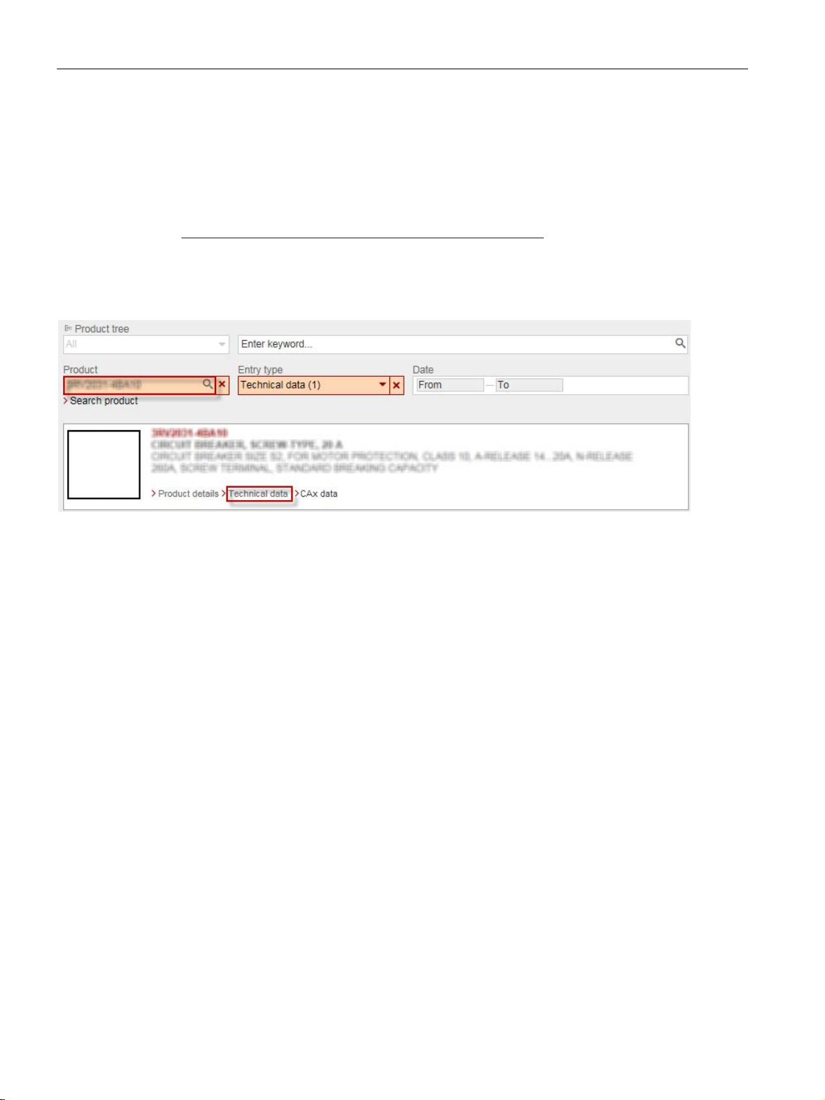
1.2 Technical data in Siemens Industry Online Support
You can find all the technical data of the product in the Siemens Industry Online Support
(https://support.industry.siemens.com/cs/ww/en/ps/16364/td).
1. Enter the full article number of the desired device in the "Product" field, and confirm with
the Enter key.
2. Click the "Technical data link.
You can compare the technical data of the products in Siemens Industry Online Support.
1. Select the products you want to compare.
2. Click the "Compare technical data" button.
To install and connect the monitoring relays, you require the operating instructions of the
monitoring relays used.
The Appendix "References (Page 361)" has a list of the operating instructions.
3UG4 / 3RR2 monitoring relays
14 Manual, 05/2016, NEB927043002000/RS-AC/004

Introduction
1.3
DataMatrix code
1P Article
number
+ S Location
Date
Serial number
Data
identifier
User
content
Separator
User content
Separator
User content
User content
Note
The information content is displayed without spaces.
1.3 DataMatrix code
A DataMatrix code is lasered onto all 3UG4/3RR2 monitoring relay devices underneath the
label.
The DataMatrix codes are standardized in ISO/IEC 16022. The DataMatrix codes on
Siemens devices use ECC200 coding for powerful error correction.
The following device information is encoded in the DataMatrix codes as a bit stream:
● Article number
● Serial number
● If applicable, MAC address
This information is stored in the following format in the DataMatrix code:
/
This machine-readable information simplifies and accelerates handling of the respective
devices.
As well as fast access to the serial numbers of the respective devices for unique
identification, the DataMatrix codes simplify communication with Siemens Technical Support.
3UG4 / 3RR2 monitoring relays
Manual, 05/2016, NEB927043002000/RS-AC/004
15
Introduction
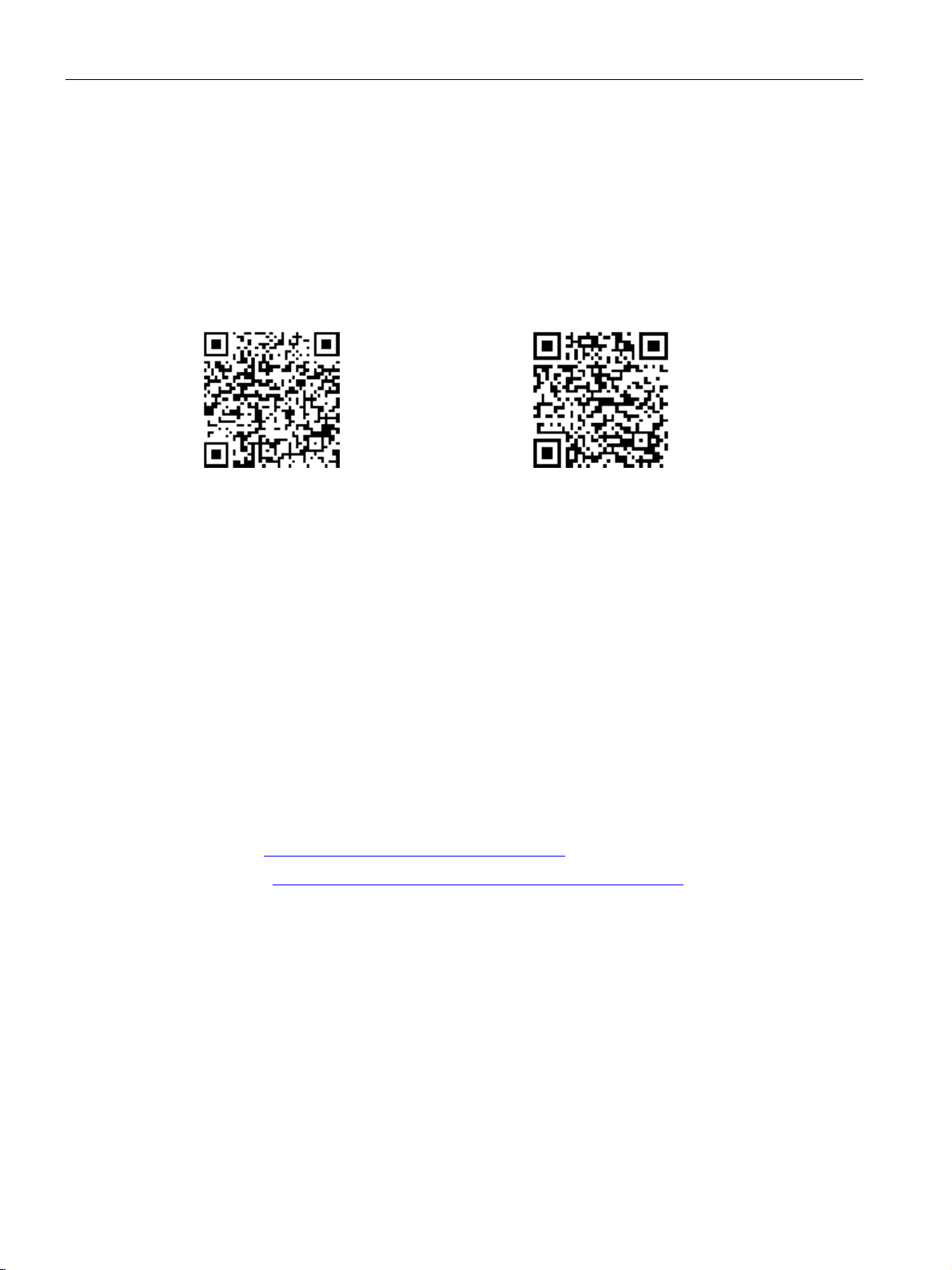
SIEMENS Industry Support App
Link for Android
Link for iOS
Recycling and disposal
Up-to-the-minute information
Technical Assistance:
or on the Internet at:
1.3 DataMatrix code
DataMatrix codes primarily enable extremely fast and convenient access to all devicespecific information relating to an article number in the SIEMENS Service&Support Portal,
such as operating instructions, manuals, data sheets, FAQs, etc.
We provide the SIEMENS Industry Support app free for this purpose and it can be used on
most commercially available smartphones and tablets.
The SIEMENS Industry Support app is available for iOS and Android-based devices and can
be accessed via the following links:
These devices can be recycled thanks to their low pollutant content. For environmentallyfriendly recycling and disposal of your electronic waste, please contact a company certified
for the disposal of electronic waste.
You can obtain further assistance by calling the following numbers:
Telephone: +49 (911) 895-5900 (8 a.m. to 5 p.m. CET)
Fax: +49 (911) 895-5907
E-mail: (mailto:technical-assistance@siemens.com)
Internet: (www.siemens.com/industrial-controls/technical-assistance)
3UG4 / 3RR2 monitoring relays
16 Manual, 05/2016, NEB927043002000/RS-AC/004

2
2.1
Standards
Applicable standards
Part 2: Additional requirements
Monitoring relays are safe to touch in accordance with IEC / EN 60529.
1)
interference. Users may have to take suitable measures.
Reference
The monitoring relays comply with the following standards:
Table 2- 1 Standards - monitoring relays
Device standards
EMC standard1)
Resistance to
extreme climates
Touch protection
• IEC / EN 60947-1 "Low-voltage switchgear and controlgear: General rules"
• IEC / EN 60947-4-1 "Contactors and motor-starters: Electromechanical
contactors and motor-starters"
• IEC / EN 60947-5-1 "Control circuit devices and switching elements:
Electromechanical control circuit devices";
VDE 0660 "Low-voltage switchgear"
• IEC / EN 61557-8 "Equipment for testing, measuring or monitoring of
protective measures - Electrical safety in low voltage distribution systems
up to 1000 V AC and 1500 V DC, Part 8: Insulation monitoring devices for
IT systems".
• DIN EN 50042 "Terminal marking"
• DIN EN 61869-2 "Instrument transformers -
for current transformers"
• IEC / EN 61000-6-2 "Generic standards - Immunity for industrial
environments"
• IEC / EN 61000-6-4 "Generic standards - Emission standard for industrial
environments"
• IEC 60721-3-3 "Classification of environmental conditions"
The monitoring relays are climate-proof according to IEC 60721-3.
• IEC / EN 60529 "Degrees of protection provided by enclosures"
This is a device of Class A. When used in domestic areas, the device can cause radio
SIRIUS components have been approved by a whole range of bodies for various sectors
(shipbuilding, etc.). An up-to-date list of approvals appears in Chapter 10 of the Catalog
IC 10 - SIRIUS "Industrial Controls" (www.siemens.com/industrial-controls/catalogs), and
more information, as well as an option to download certificates, can be obtained on the
Internet (www.siemens.com/automation/csi_en).
3UG4 / 3RR2 monitoring relays
Manual, 05/2016, NEB927043002000/RS-AC/004
17

Safety information
2.2
Product-specific safety information
Intended use
WARNING
Intended use
Can Cause Death, Serious Injury, or Property Damage.
Hazardous Voltage
WARNING
Hazardous Voltage.
Radio interference
Note
The devices have been built as Class
Use of these devices in domestic areas can result in radio interference!
2.3
Approvals, test certificates, characteristics
Approvals, test certificates, characteristics
2.2 Product-specific safety information
The devices may only be used for the applications described in the catalog and the
technical description, and only in conjunction with equipment or components from other
manufacturers which have been approved or recommended by Siemens.
This product can function correctly and reliably only if it is transported, stored, assembled,
and installed correctly, and operated and maintained as recommended.
Before you run any sample programs or programs that you have written yourself, make
sure that running the plant cannot cause injury to anyone else or damage to the machine
itself.
Will cause death or serious injury.
Turn off and lock out all power supplying this device before working on this device.
A devices.
3UG4 / 3RR2 monitoring relays
18 Manual, 05/2016, NEB927043002000/RS-AC/004
You can find an overview of the certifications available for low-voltage controls and
distribution products and other technical documentation, updated daily, on the Internet
(www.siemens.com/industrial-controls/support).
You will find further information in the Catalog IC 10 - SIRIUS "Industrial Controls," Chapter
10 (www.siemens.com/industrial-controls/catalogs).

3
3.1
Product description
Product description
The tried and tested SIRIUS monitoring relays for electrical and mechanical quantities
enable constant monitoring of all important characteristic quantities that provide information
about the reliability performance of the plant. Sudden disturbances and gradual changes,
which may reveal a maintenance requirement, for example, are both indicated. By means of
relay outputs, the monitoring relays enable direct shutdown of the affected sections of the
plant as well as issuing an alarm (e.g. by switching on a warning lamp). To respond flexibly
to short-term disturbances such as voltage dips or load variation, the monitoring relays have
settable delay times. This avoids unnecessary alarming and shutdowns while enhancing
plant availability.
The individual 3UG4 monitoring relays offer the following functions in various combinations:
● Undershoot and/or overshoot of liquid levels
● Phase sequence
● Phase failure, neutral failure
● Phase asymmetry
● Undershoot and/or overshoot of voltage thresholds
● Undershoot and/or overshoot of current thresholds
● Undershoot and/or overshoot of power factor thresholds
● Monitoring of the active current or apparent current
● Monitoring of the fault current
● Monitoring the insulation resistance
● Undershoot and/or overshoot of speed thresholds
The 3RT2 contactors for mounting on 3RR2 current monitoring relays offer:
● Phase sequence
● Phase failure
● Undershoot and/or overshoot of current thresholds
● Monitoring of the active current or apparent current
● Monitoring of the fault current
3UG4 / 3RR2 monitoring relays
Manual, 05/2016, NEB927043002000/RS-AC/004
19

System overview
3.2
Application planning
Installation altitude
Operating conditions and resistance to extreme climates
Special application environments
3.2 Application planning
The following information must be taken into account when planning applications involving
the SIRIUS monitoring relays.
The monitoring relays are approved for installation altitudes up to 2,000 m. The reduced air
density at altitudes higher than 2,000 meters affects the electrical characteristics of the
monitoring relays. The reduction factors which have to be taken into account when using
monitoring relays at altitudes higher than 2,000 m can be obtained on request on the Internet
(www.siemens.com/automation/csi_en).
The monitoring relays are climate-proof. They are intended for use in enclosed spaces in
which no severe operating conditions prevail (e.g. dust, caustic vapors, hazardous gases).
Appropriate measures must be taken when installing in areas subject to dust and humidity.
Condensation on the devices is not permissible.
The SIRIUS devices have been approved by a whole range of bodies for various sectors
(shipbuilding, etc.). An up-to-date list of approvals is provided in Chapter 10 of the Catalog
IC 10 - SIRIUS "Industrial Controls." You will find more information and an option to
download certificates on the Internet (www.siemens.com/automation/csi_en).
3UG4 / 3RR2 monitoring relays
20 Manual, 05/2016, NEB927043002000/RS-AC/004
System overview
3.3
Connection methods
3.3.1
Screw-type connection
Screw-type connection
Connection cross-sections of the removable terminal blocks with screw-type connections
Removable terminal
1 x (0.5 to 4) mm²
AWG
2 x (20 to 14)
3.3 Connection methods
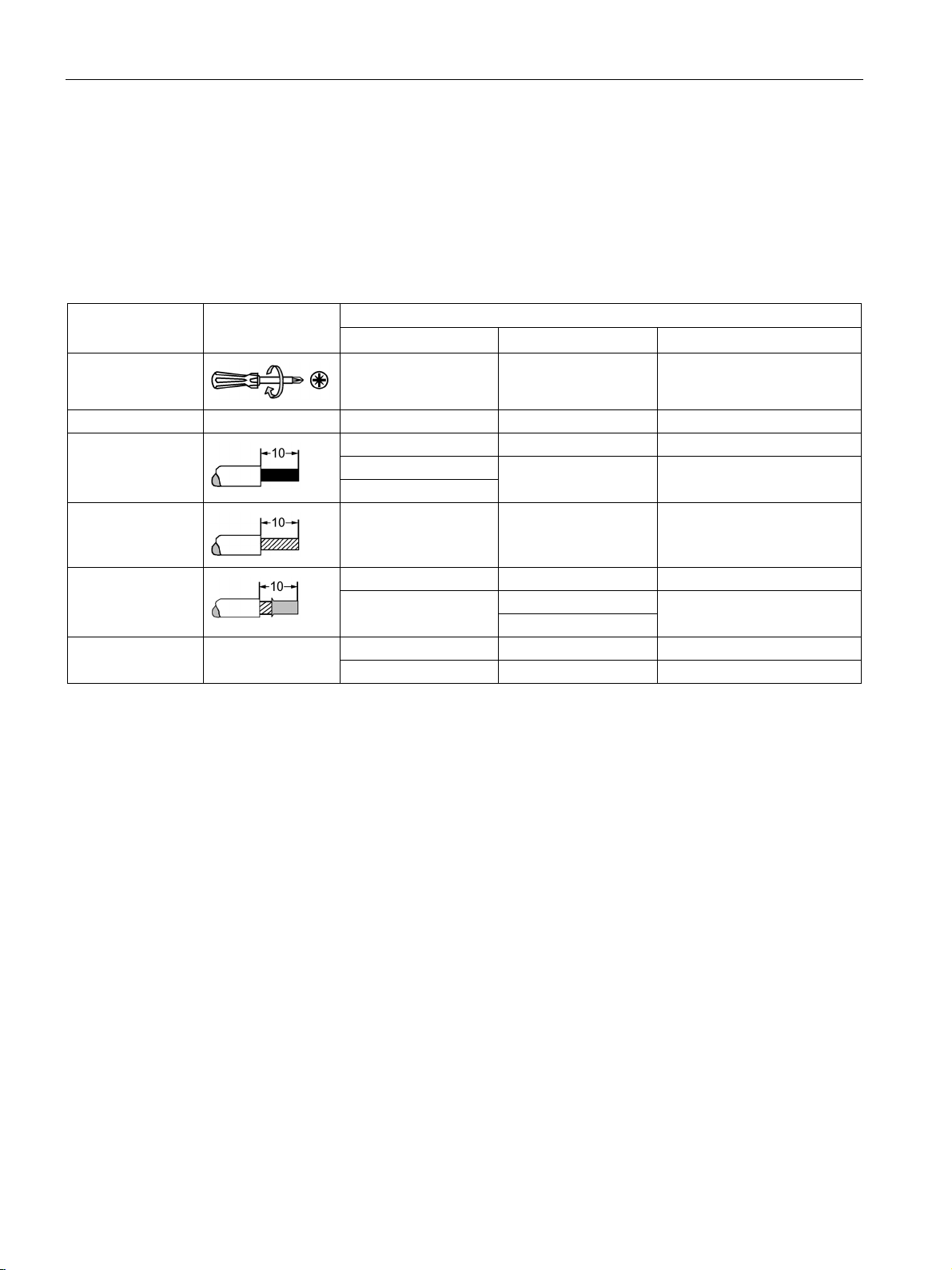
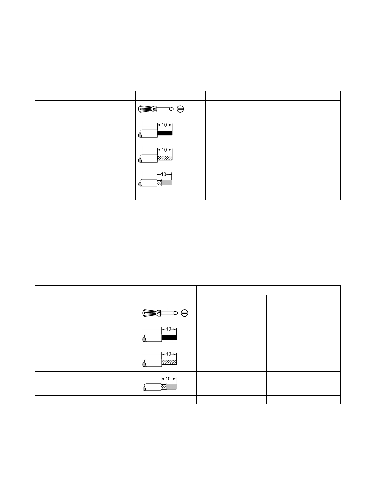
Use the following tool to establish the connection: All SIRIUS monitoring relays feature
size PZ 2 screws for Pozidriv screwdrivers.
The devices have screw terminals with captive screws and washers. The screw terminals
also allow for the connection of 2 conductors with different cross-sections.
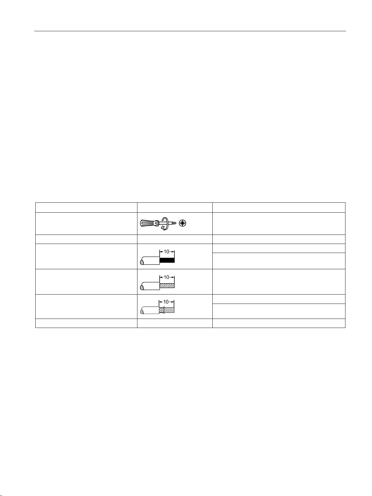
Table 3- 1 Removable terminal block with screw-type connections - monitoring relays
Tool
Tightening torque 0.8 to 1.2 Nm
Solid and stranded
Finely stranded without end sleeve
Finely stranded with end sleeve
Pozidriv size PZ 2, Ø 5 to 6 mm
2 x (0.5 to 2.5) mm²
---
1 x (0.5 to 2.5) mm²
2 x (0.5 to 1.5) mm²
3UG4 / 3RR2 monitoring relays
Manual, 05/2016, NEB927043002000/RS-AC/004
21
System overview
Connection cross-sections of the permanently connected terminal blocks with screw-type connections
Permanently connected terminal
Size S00
Size S0
Size S2
Tightening torque
0.8 to 1.2 Nm
2 - 2.5 Nm
3 to 4.5 Nm (27 to 40 lb.in)
2 x (0.5 to 1.5) mm²
2 x (1 to 2.5) mm²
2 x (1.0 to 35 mm²)
2 x (0.75 to 2.5) mm²
2 x (0.5 to 1.5) mm²
2 x (1 to 2.5) mm²
2 x (1.0 to 25 mm²)
2 x (2.5 to 6) mm²
max. 1 x 10 mm²
2 x (20 to 14)
2 x (16 to 12)
2 x (18 to 2)
3.3 Connection methods
The following table lists the permissible conductor cross-sections for the main conductor
connections of 3RR2 current monitoring relays with analog and digital setting (size S00, S0
and S2) with screw-type connections.
Table 3- 2 Permanently connected terminal block with screw-type connection - Main conductor terminals of the 3RR2
current monitoring relays
Tool
Solid and stranded
Finely stranded
without end sleeve
Finely stranded
with end sleeve
AWG
Pozidriv size PZ 2,
Ø 5 to 6 mm
max. 2 x (1 ... 4) mm²
--- --- ---
2 x (0.75 to 2.5) mm²
1 x 12 2 x (14 to 8) 1 x (18 to 1)
Pozidriv size PZ 2,
Ø 5 to 6 mm
2 x (2.5 to 10) mm² 1 x (1.0 to 50 mm²)
Pozidriv size PZ 2
Ø 5 to 6 mm
1 x (1.0 to 35 mm²)
3UG4 / 3RR2 monitoring relays
22 Manual, 05/2016, NEB927043002000/RS-AC/004
System overview
3.3.2
Spring-loaded connection
Spring-loaded connection
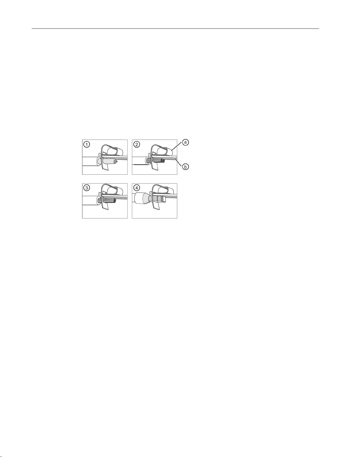
①
Solid
②
Finely stranded
③
Stranded
④
Finely stranded with end sleeve
a
Spring-loaded terminal
b
Busbar
3.3 Connection methods
All SIRIUS monitoring relays have spring-loaded connections. They make wiring quick and
maintenance-free, while also meeting high demands in terms of vibration and shock
resistance. If the cross-section of a connectable wire is greater than 6 mm², the forces
required for operation of the tension spring are so high that the spring-loaded connection can
no longer be used in a problem-free manner. For this reason, size S2 current monitoring
relays are only offered with screw-type or spring-loaded terminals in the control circuit. The
terminals of the main current paths are always screw-type terminals.
Image 3-1 Spring-loaded terminal
The conductors can be clamped directly or you can pre-treat them to add a form of splice
protection. This could involve attaching end sleeves or pin cable lugs to the ends of the
conductors; the tidiest solution is to use conductors whose ends have been sealed by means
of ultrasound.
3UG4 / 3RR2 monitoring relays
Manual, 05/2016, NEB927043002000/RS-AC/004
23

System overview
3.3 Connection methods
The devices are equipped with a two-wire terminal, i.e. two independent connections for
each current path (exception: in the case of 3RR2, terminals of the main current paths have
one clamping point). Just one conductor is connected to each clamping point. The springloaded terminal presses the conductor against the busbar, which curves around inside the
terminal. The high contact pressure per unit area achieved in this way is gas-tight. The
spring-loaded terminal presses flat against the conductor, but does not damage it. The
spring force of the spring-loaded terminal has been dimensioned such that the clamping
force adjusts to the conductor diameter automatically. This ensures that any conductor
deformation caused by settling, creepage, or yielding is compensated for. The clamping
point cannot become loose of its own accord. This connection is vibration- and shock-proof.
Vibrations or shocks will not damage the conductor, nor will they cause contact separation.
These terminals are particularly well suited for use with machines and systems which are
subject to stresses such as these, e.g. vibrators, rail vehicles, and elevators.
The contact pressure between the conductor and the busbar is set to an optimum level, so
this clamp connection is appropriate for high-voltage applications, as well as for transferring
voltages and currents in the mV or mA range within instrumentation and electronic
components.
A standardized screwdriver (3 mm slot; 3RA2908-1A) is offered in the Catalog IC10
"Industrial Controls" (www.siemens.com/industrial-controls/catalogs) as an actuation tool for
opening the spring-loaded terminals.
3UG4 / 3RR2 monitoring relays
24 Manual, 05/2016, NEB927043002000/RS-AC/004
System overview
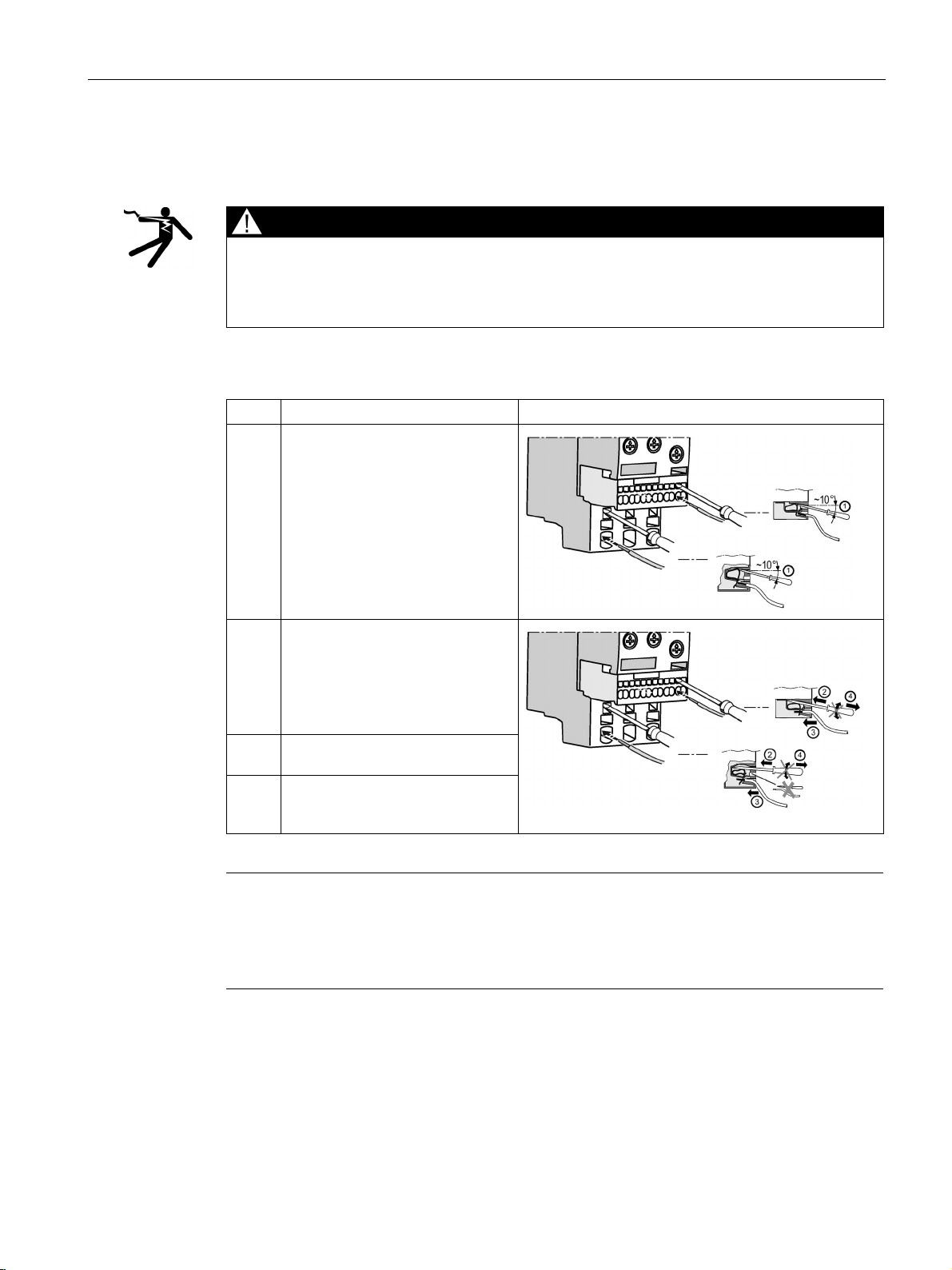
Spring-loaded connection for mountable 3RR2 current monitoring relays
DANGER
Hazardous Voltage.
Step
Instructions
Figure
automatically.
connection slot.
is now securely clamped.
Note
Damage to spring-loaded terminal on the 3RR2 current monitoring relay!
If you insert the screwdriver into the central opening (main circuit S00 and S0 only) on the
spring
Do not insert the screwdriver into the central opening on the spring-loaded terminal.
3.3 Connection methods
The table below describes the procedure for creating a spring-loaded connection:
Will cause death or serious injury.
Turn off and lock out all power supplying this device before working on this device.
Table 3- 3 Connecting the 3RR2 current monitoring relay spring-loaded terminal
1 Insert the screwdriver into the
respective operating slot.
2 Press the screwdriver down, then
push it into the operating slot as far
as it will go.
The screwdriver blade keeps the
spring-loaded terminal open
3 Insert the conductor into the oval
4 Remove the screwdriver. The
terminal closes and the conductor
-loaded terminal, this could damage the terminal.
3UG4 / 3RR2 monitoring relays
Manual, 05/2016, NEB927043002000/RS-AC/004
25
System overview
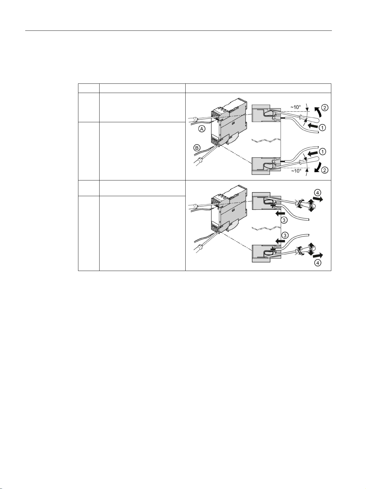
Spring-loaded terminal for 3UG4 monitoring relay
Step
Operating instruction
Figure
side.
connection slot.
3.3 Connection methods
Table 3- 4 Connecting the monitoring relay spring-loaded terminal
1 Insert the screwdriver into the
topmost (A) or bottommost (B)
operating slot on the right-hand
2 Press the screwdriver up (A) or
down (B), then push it into the
operating slot as far as it will go.
The screwdriver blade keeps the
spring-loaded terminal open
automatically.
3 Insert the conductor into the oval
4 Remove the screwdriver. The
terminal closes and the
conductor is now securely
clamped.
3UG4 / 3RR2 monitoring relays
26 Manual, 05/2016, NEB927043002000/RS-AC/004
System overview
Connection cross-sections of the removable terminal blocks with a spring-loaded connection (3RR
and 3UG)
Removable terminal
AWG
2 x (24 to 16)
Connection cross-sections of the permanently connected terminal blocks with a spring-loaded
connection
Permanently connected terminal
Size S00
Size S0
3.3 Connection methods
Table 3- 5 Removable terminal block with spring-loaded connections - monitoring relays
Tool
Solid and stranded
Finely stranded without end sleeve
Finely stranded with end sleeve
Ø 3.0 x 0.5 (3RA2908-1A)
2 x (0.25 to 1.5) mm²
2 x (0.25 to 1.5) mm²
2 x (0.25 to 1.5) mm²
The following table lists the permissible conductor cross-sections for the main conductor
terminals of the 3RR2 current monitoring relays for analog and digital setting (size S00 and
S0) with a spring-loaded connection.
Table 3- 6 Permanently connected terminal block with spring-loaded connection - main conductor terminals of
3RR2 current monitoring relays
Tool
Solid
Finely stranded without end sleeve
Finely stranded with end sleeve
AWG 1 x (20 to 12) 1 x (18 to 8)
3UG4 / 3RR2 monitoring relays
Manual, 05/2016, NEB927043002000/RS-AC/004
Ø3.0 x 0.5 (3RA2908-1A) Ø3.0 x 0.5 (3RA2908-1A)
1 x (0.5 to 4) mm² 1 x (1 to 10) mm²
1 x (0.5 to 2.5) mm² 1 x (1 to 6) mm²
1 x (0.5 to 2.5) mm² 1 x (1 to 6) mm²
27
System overview
3.3.3
Device replacement by means of removable terminals
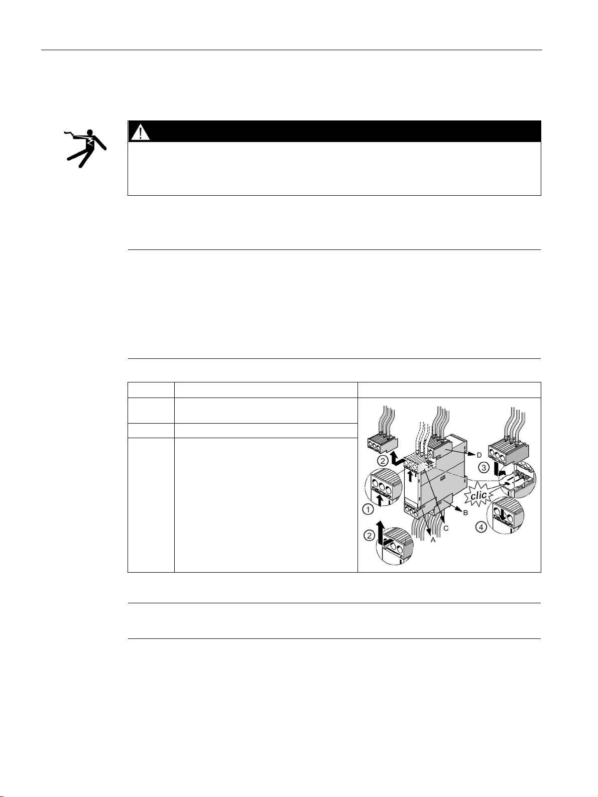
DANGER
Hazardous Voltage
Note
The terminals can only be dismantled in the
monitoring relay:
1.
2.
3.
4.
Step
Instructions
Figure
2
Remove the terminal to the front.
Note
The procedure is similar on devices with fewer connection terminals.
3.3 Connection methods
Will cause death or serious injury.
Turn off and lock out power before working on this equipment.
The removable terminals of 3UG4 monitoring relays facilitate device replacement when
necessary. The mechanical coding on the terminals prevents mix-ups.
following order due to their arrangement on the
Lower, front terminal (A)
Lower, rear terminal (B)
Upper, front terminal (C)
Upper, rear terminal (D)
1 Press the interlock in the direction of the
removable terminal.
3 / 4 Attach the new terminal and press the
terminal into the device until the interlock
audibly engages.
3UG4 / 3RR2 monitoring relays
28 Manual, 05/2016, NEB927043002000/RS-AC/004

System overview
3.4
Mounting / removal
3.4.1
Mounting 3RR2 current monitoring relay
Mounting options
Minimum clearance
Mounting position
3.4 Mounting / removal
3RR2 current monitoring relays are matched to 3RT2 contactors and 3RF34 (size S0) solidstate contactors in terms of their electrical and mechanical features. As a result, direct
mounting can be achieved easily.
Alternatively, the devices can also be installed individually in the case of stand-alone
assembly or if a 3RU2 / 3RB3 overload relay is being used at the same time. The
accessories required for separate mounting are described in Chapter "Terminal support for
stand-alone assembly (Page 324)."
The following minimum clearances from grounded and live parts must be complied with
when installing the 3RR2 monitoring relay:
● At the side: 6 mm
● Forward (on front): 6 mm
It can be mounted in any position.
3UG4 / 3RR2 monitoring relays
Manual, 05/2016, NEB927043002000/RS-AC/004
29
System overview
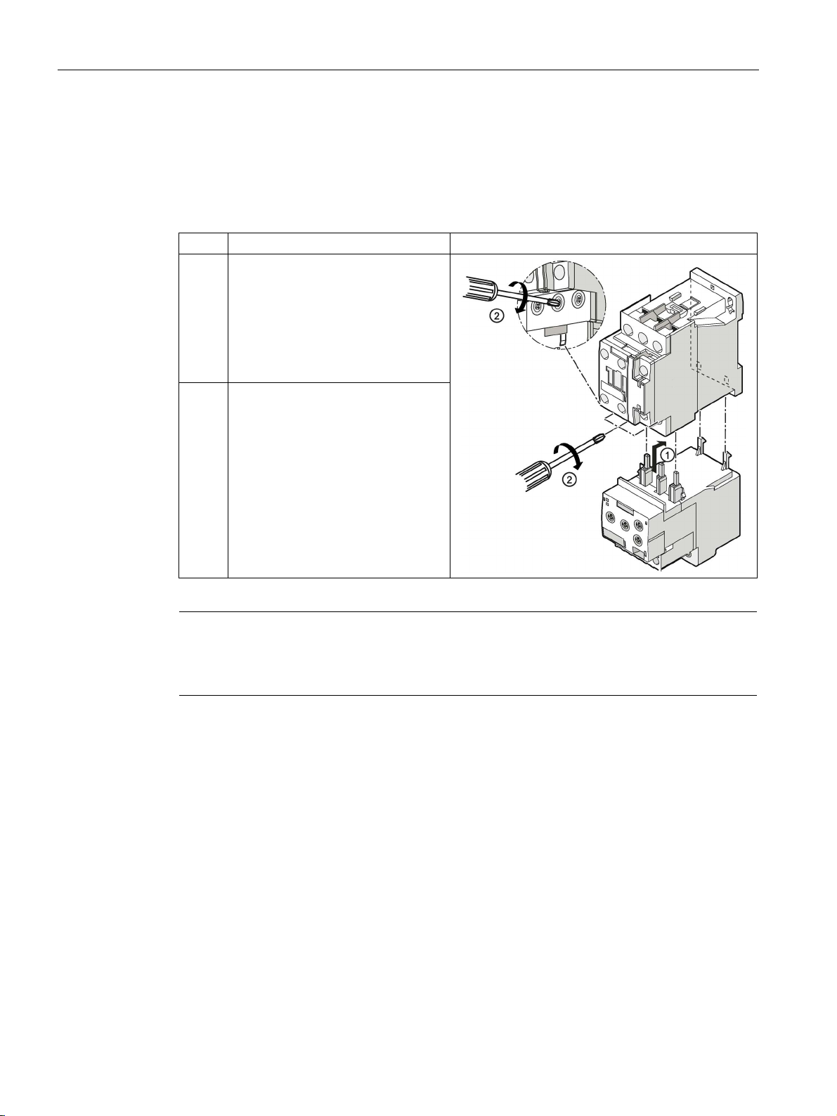
Direct mounting on 3RT2 contactor / 3RF34 (size S0) solid-state contactor
Step
Instructions
Figure
contactor.
Note
The connection cross
with screw
(Page
3.4 Mounting / removal
The diagram below shows an example mounting scenario based on mounting the
3RR21 analog setting current monitoring relay, size S0, on the 3RT2 contactor.
Table 3- 7 Mounting of 3RR2 current monitoring relay, screw-type connection system (size S0)
1 Push the current monitoring relay into
the contactor from below. Attach the
two hooks on the current monitoring
relay to the two openings on the rear
of the contactor. This pushes the
main current contacts into the
corresponding terminals on the
2 Tighten the screws on the contactor
with a Pozidriv size 2 (S00) or
Pozidriv size 3 (S0) screwdriver
(tightening torque 0.8 ... 1.2 Nm).
Check that the cable is clamped tight.
-sections of the removable and permanently connected terminal blocks
-type connections are described in the Chapter "Screw-type connection
21)".
3UG4 / 3RR2 monitoring relays
30 Manual, 05/2016, NEB927043002000/RS-AC/004
 Loading...