

Page 1
3RW30/3RW40 Soft Starters
© Siemens AG 2008
Catalog News LV 1 N • January 2008
www.siemens.com/automation
Page 2

Related catalogs Contents
© Siemens AG 2008
Low-Voltage Controls and
Distribution
SIRIUS
·
SENTRON · SIVACON
Order No.:
Catalog
E86060-K1002-A101-A7-7600
Technical Information incl.
Low-Voltage
Controls and Components
for Applications according to UL
Order no.:
E86060-K1816-A101-A1-7600
Industrial Communication
Industrial Communication
for Automation and Drives
Order No.:
E86060-K6710-A101-B6-7600
E86060-K6710-A121-A2-7600
SICUBE
System Cubicles and
Cubicle Air-Conditioning
Order No.:
E86060-K1920-A101-A3-7600
Systems · Controlgear: Contactors and contactor assemblies,
solid-state switching devices · Protection equipment · Load
feeders, motor starters and soft starters · Monitoring and
control devices
LV 1
LV 1 T
LV 16 SIRIUS 3RV17 and 3RV18 circuit breakers according to
IK PI
IK PI N
LV 50 System cubicles · Cubicle modifications · Cubicle expansion
signaling devices · Transformers · Power supplies · Planning
and configuration with SIRIUS · Power Management System ·
SIVACON Power, distribution boards, busway and cubicle
systems
power distribution · Air circuit breakers, molded case circuit
breakers, switch disconnectors
distribution· BETA low-voltage circuit protection
UL 489 · SIVACON Components for 8US Distribution Systems
according to UL 508A · SENTRON 3WL5 air circuit breakers/
non-automatic air circuit breakers according to UL 489/IEC
SENTRON 3VL Molded Case Circuit Breakers according to
UL 489/IEC · ALPHA Devices according to UL Standard ·
BETA Devices according to UL standard
PROFINET/Industrial Ethernet · Industrial Mobile
Communicaton
ET 200 distributed I/Os · AS-Interface to EN 50295/IEC 61158 ·
Remote operation with SINAUT Telecontrol · Routers ·
ECOFAST system
components
Cubicle solutions in applications · Cubicle air-conditioning ·
Special colors
· Detecting devices · Commanding and
· SENTRON switching and protection devices for
· Software for power
·
· PROFIBUS to IEC 61158/EN 50170 · SIMATIC
· Accessories · Special cubicles
SIDAC
Reactors and Filters
Order No.:
E86060-K2803-A101-A4-7600
SIVACON 8PS
CD-K, BD01, BD2
Busbar Trunking Systems
up to 1250 A
Order No.:
E86060-K1870-A101-A3-7600
Automation & Drives
The A&D Offline Mall
CD-ROM:
E86060-D4001-A110-C6-7600
DVD:
E86060-D4001-A510-C6-7600
A&D Mall
Internet:
http://www.siemens.com/
automation/mall
Catalog-PDF
Internet:
http://www.automation.
siemens.com/cd
Registered trademarks Technical Assistance
LV 60 Commutating reactors for converters · Mains reactors for fre-
LV 70 Busbar trunking systems, overview · CD-K system
CA 01 All Automation and Drives products,
quency converters
Ferrite output reactors · Iron-core smoothing reactors · Smoothing air-core reactors · Filter reactors · Application-specific
reactors
Sinewave filters
(25 A to 40 A)
BD2 system (160 A to 1250 A)
including those in the catalogs listed above.
All Automation and Drives products,
including those in the catalogs listed above.
All catalogs for low-voltage controls and distribution can be
downloaded as PDF files.
· Radio interference suppression filters · dv/dt filters ·
· Iron-core output reactors ·
· BD01 system (40 A to 160 A) ·
All product designations may be registered trademarks or
product names of Siemens AG or other supplying
companies. Third parties using these trademarks or product
names for their own purposes may infringe upon the rights of
the trademark owners.
Further information about low-voltage controls is available on
the Internet at:
http://www.siemens.com/lowvoltage
Expert technical assistance for
Low-voltage controls and
electrical installation.
Tel.: +49 (9 11) 8 95-59 00
Fax: +49 (9 11) 8 95-59 07
E-Mail: technicalassistance@siemens.com
Page 3

3RW30/3RW40
© Siemens AG 2008
SIRIUS Soft Starters
Catalog News
LV 1 N · 01/2008
Invalid LV 1 · 2008 and LV 1 T · 2008,
Chapter 6, Load Feeders, Motor Starters
and Soft Starters,
Section: 3RW30 and 3RW40 Soft Starters
Contact your local Siemens
representative for further information
© Siemens AG 2008
The products and systems listed in this catalog are manufactured
using a certified quality
management system
which complies with
EN ISO 9001 (for the
Certificate Register No.
see the Appendix).
The TÜV certificate is
recognized in all IQ Net
countries.
s
Page 4

© Siemens AG 2008
Page 5
Introduction
© Siemens AG 2008
1
Siemens Automation and Drives. Welcome.
Sharpen your competitive edge. Totally Integrated Automation.
Integrated energy distribution from a single source.
Totally Integrated Power.
Low-Voltage Controls and Distribution - The basis for progressive
solutions.
SIRIUS Industrial Controls
Low-Voltage Power Distribution
Systems
2
AS-Interface
ECOFAST System
SIRIUS Safety Integrated
PROFIBUS
SIRIUS Modular System
Power Supplies
11
4AV Non-Stabilized Power Supplies
6EP Stabilized Power Supplies
- SITOP
- LOGO!Power
Engineering Software
12
Planning and Configuration with SIRIUS
Motor Starter ES
ECOFAST ES
SIMOCODE ES
Soft Starter ES
Controls –
3
Contactors and Contactor Assemblies
3RT, 3TB, 3TF Contactors for Switching Motors
3RA13, 3RA14, 3TD, 3TE Contactor Assemblies
3RT, 3RH, 3TB, 3TC, 3TH, 3TK Contactors for Special Applications
3RH, 3TH Contactor Relays · 3RT Coupling Relays
3TX7, 3RS18 Coupling Relays · LZS, LZX
3TG10 Power Relays/Miniature Contactors
Controls –
4
Solid-State Switching Devices
For resistive loads:
3RF20, 3RF21, 3RF22 Solid-State Relays
3RF23, 3RF24 Solid-State Contactors · 3RF29 Function Modules
For switching motors:
3RF24 Solid-State Contactors and Solid-State Reversing Contactors
Protection Equipment
5
3RV Motor Starter Protectors
3RB2 Solid-State Overload Relays
3RU1 Thermal Overload Relays
Load Feeders, Motor Starters and Soft Starters
6
3RW Soft Starters
3RA Fuseless Load Feeders
3RA71 Load Feeders with Safety Integrated
AS-Interface Motor Starters and Soft Starters
ET 200S, ET 200pro Motor Starters
ET 200S Safety Motor Starter Solutions Local / PROFIsafe
ECOFAST Motor Starters and Soft Starters
3RE Encapsulated Starters
Monitoring and Control Devices
7
SIMOCODE 3UF Motor Management and Control Devices
LOGO! Logic Modules · 3RP, 3RT19 Timing Relays
3UG Monitoring Relays for Electrical and Additional Measurements
3RS10, 3RS11 Temperature Monitoring Relays
S I R I U S I n d u s t r i a l C o n t r o l s
3RN1 Thermistor Motor Protection
3TK28 Safety Relays
3RS17 Interface Converters
Detecting Devices
8
3SE2, 3SE3, 3SE5, 3SF1 Position Switches
3SF1 Hinge Switches
3SE6 Magnetically Operated Switches
Plug-In Relays ·
Power Management System
13
System Overview
- SIMATIC powercontrol
- SIMATIC powercost
SIVACON Power Distribution Boards,
14
Busway Systems and Cubicle Systems
S8, 8PV and 8PT Power Distribution Boards and Motor Control
Centers , 8PS Busbar Trunking Systems · 8MC, 8MF Cubicle
Systems, 8MR, 8ME Cubicle Air-Conditioning
ALPHA 630-DIN Floor-Mounted Distribution Boards · ALPHA FIX
Terminal Blocks; ALPHA 8HP Molded-Plastic Distribut ion Systems
Components for 8US, 8UC, 4NC Distribution Systems:
SENTRON Switching and Protection Devices
15
for Power Distribution
3WL Air Circuit Breakers
SENTRON Switching and Protection Devices
16
for Power Distribution
3VL, 3VF2 Molded Case Circuit Breakers
SENTRON Switching and Protection Devices
17
for Power Distribution
3KA, 3KE, 3LD Switch Disconnectors
3KL, 3KM, 3NJ6 Switch Disconnectors with Fuses
3NP, 3NJ4, 3NJ5 Fuse Switch Disconnectors
L o w - V o l t a g e P o w e r D i s t r i b u t i o n
Software for Power Distribution
18
Dimensioning with SIMARIS design
Configuring, Visualizing and Controlling with SIMATIC
Configuring, Visualizing and Controlling with SENTRON
9
10
Commanding and Signaling devices
3SB2, 3SB3, 3SF5 Pushbutton Units and Indicator Lights
3SE7, 3SF2 Cable-Operated Switches
3SE2, 3SE3 Foot Switches
8WD4 Signaling Columns
8WD5 Integrated Signal Lamps
Transformers
Single-Phase Transformers
Three-Phase Transforme r s
BETA Low-Voltage Circuit Protection
19
Miniature Circuit Breakers (MCBs)
Residual Current Protective Devices
...
Low-Voltage Fuse Systems
SITOR Semiconductor Fuses
SR 60 Busbar Systems
Overvoltage Protection Devices
Socket Outlets
Measuring Devices
Appendix
20
Glossary · Training · Ordering notes · Further documentation ·
Standards and approvals · Quality management · Online
services · Customer support · Software licenses · Subject index
Order number index including export markings ·
Terms and conditions of sale and delivery
Page 6
Explanations
© Siemens AG 2008
■
General information
Things you should know about Catalog LV 1 · 2008 and Technical Information LV 1 T · 2008
Catalog LV 1 · 2008 contains selection- and orderrelevant data under the topic headings "Overview",
"Benefits", "Application", "Selection and ordering
data", "Accessories", "Options" and "More information".
Delivery time class (DT)
} Preferred type
A 2 working days
B 1 week
C 3 weeks
D 6 weeks
X On request
Preferred types are available immediately from
stock, i.e. are dispatched within 24 hours.
Normal quantities of the products are usually delivered within the specified time following receipt of
your order at our branch.
In exceptional cases, the actual delivery time may
differ from that specified.
Price units (PU)
The price unit defines the number of units, sets or
meters to which the specified price and weight
apply.
Packaging sizes (PS)
The packaging size defines the number, e.g. of
units, sets or meters, for outer packaging.
Only the quantity defined by the packaging size or
a multiple thereof can be ordered!
Price groups (PG)
Each product is assigned to a price group.
Weight
The defined weight in kg refers to the price unit
(PU).
Dimensions
All dimensions in mm.
The topics "Design", "Function", "Integration", Configuration", "Programming",
"Technical specifications", "Characteristic curves", "Schematics" and "Dimensional drawings" can be found if required in the Technical Information
LV 1 T · 2008.
The Technical Information LV 1 T is saved as a PDF file on the
CD-ROM which is enclosed with this catalog (inside front cover).
The delivery times apply up to the ramp at Siemens AG (products ready for
dispatch). The transport times depend on the destination and type of shipping.
The standard transport time for Germany is 1 day.
The delivery times specified here represent the state of 10/2007. They are permanently optimized. Up-to-date information can be found at
http://www.siemens.com/automation/mall.
Note:
For transformers, delivery time class B is applicable to an order quantity of up
to 5 units. For an order quantity of more than 5 units, delivery time class C is
applicable instead of delivery time class B.
For multi-unit packing and reusable packaging see Appendix
■
Order number index
Order number index with export regulation
Order number Export regulation Page
3R
3RA N N 6/5, 6/11
3RP N N 6/5
3RT N N 6/5, 6/10
3RU19 00-1 N N 6/10
3RU19 00-2 N N 6/10
3RW30 0 N N 6/4
3RW30 1 N N 6/4
3RW30 2 N N 6/4
3RW30 3 EAR99 N 6/4
3RW30 4 EAR99 N 6/4
3RW40 2 N N 6/7 ... 8
3RW40 3 N N 6/7 ... 8
3RW40 4 N N 6/7 ... 8
3RW40 5 N N 6/9
3RW40 7 N N 6/9
3RW49 N N 6/10 ... 11
4
ECCN AL
Siemens LV 1 N SIRIUS Soft Starters · 1/2008
Order number Export regulation Page
ECCN AL
3S
3SB N N 6/10
3SX N N 6/10
3Z
3ZX on request 6/5, 6/11
Page 7

3RW30/3RW40
© Siemens AG 2008
SIRIUS Soft Starters
Catalog
Technical Information
3RW Soft Starters
General data
6/2 - Overview
3RW30 for standard applications
6/3 - Overview
6/3 - Application
6/4 - Selection and ordering data
3RW40 for standard applications
6/6 - Overview
6/6 - Application
6/7 - Selection and ordering data
3RW Soft Starters
3RW30 for standard applications
6/12 - Function
6/12 - Technical specifications
6/21 - Characteristic curves
6/21 - More information
3RW40 for standard applications
6/23 - Function
6/24 - Technical specifications
6/34 - Characteristic curves
6/35 - More information
Project planning aids
6/37 - Dimensional drawings
6/39 - Schematics
Siemens LV 1 N SIRIUS Soft Starters ·
01/2008
Page 8
3RW Soft Starters
© Siemens AG 2008
General data
■
Overview
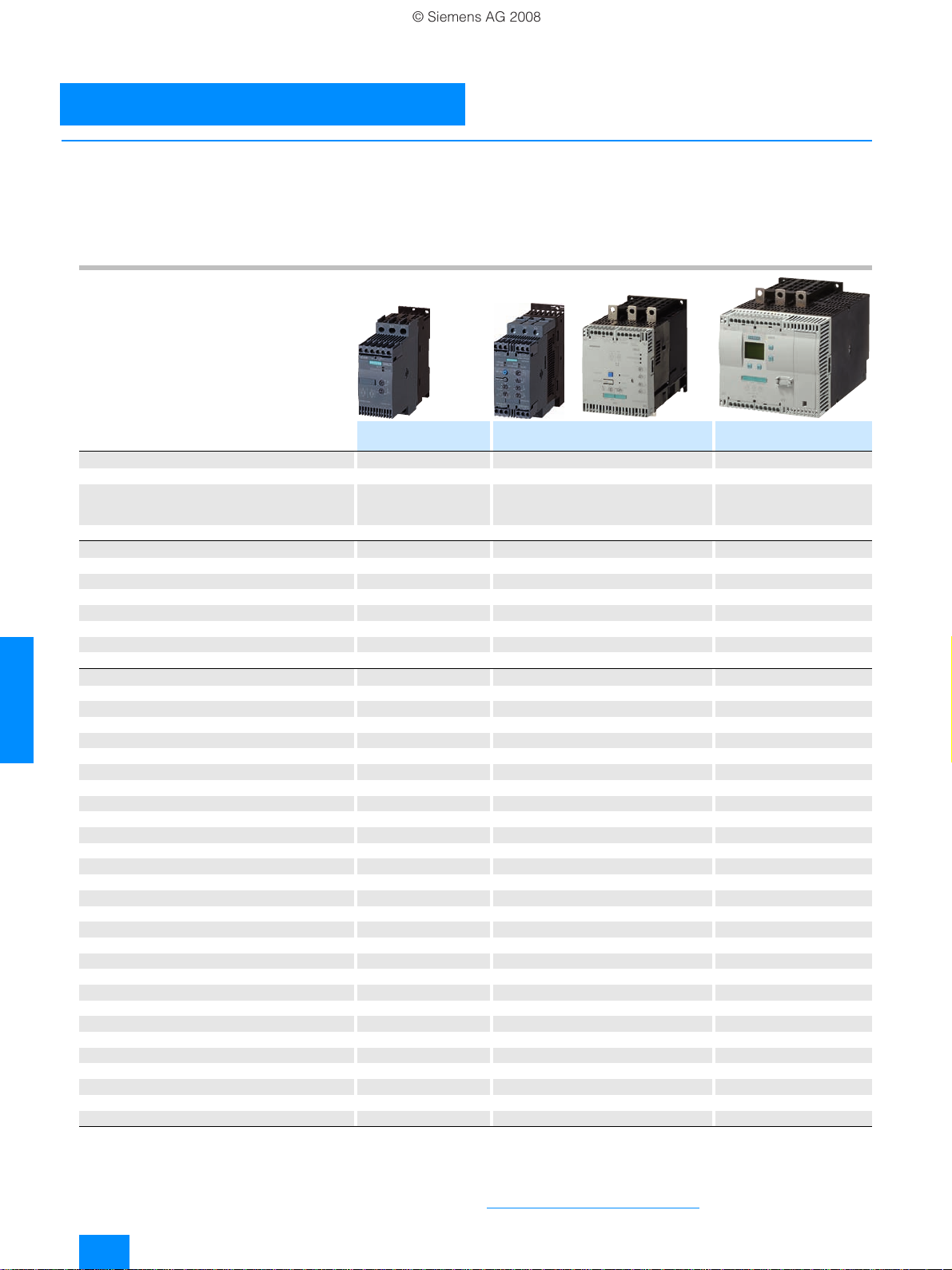
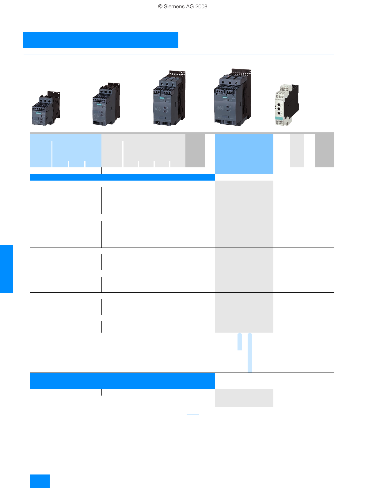
The advantages of the SIRIUS soft starters at a glance:
• Soft starting and smooth ramp-down
1)
• Stepless starting
• Reduction of current peaks
• Avoidance of mains voltage fluctuations during starting
• Reduced load on the power supply network
SIRIUS 3RW30 SIRIUS 3RW40 SIRIUS 3RW44
Standard applications Standard applications High-Feature applications
Rated current up to 40 °C A 3...106 12.5 ... 432 29 ... 1214
Rated operational voltage V 200 ... 480 200 ... 600 200 ... 690
Motor rating at 400 V
• Inline circuit kW 1.5 ... 55 5.5 ... 250 15 ... 710
• Inside-delta circuit kW -- -- 22 ... 1200
Ambient temperature °C -25 ... +60 -25 ... +60 0 ... +60
Soft starting/ramp-down ✔
Vol t a g e ramp ✔✔ ✔
Starting/stopping voltage % 40 ... 100 40 ... 100 20 ... 100
Starting and ramp-down time s 0...20 0...20 1...360
Torque control -- -- ✔
Starting/stopping torque %-- -- 20...100
Torque limit % -- -- 20 ... 200
Ramp time s -- -- 1 ... 360
Integral bypass contact system ✔ ✔ ✔
6
Intrinsic device protection -- ✔✔
Motor overload protection -- ✔ ✔
Thermistor motor protection -- ✔
Integrated remote RESET -- ✔
Adjustable current limiting -- ✔✔
Inside-delta circuit -- -- ✔
Breakaway pulse -- -- ✔
Creep speed in both directions of rotation -- -- ✔
Pump ramp-down -- -- ✔
DC braking -- -- ✔
Combined braking -- -- ✔
Motor heating -- -- ✔
Communication -- -- with PROFIBUS DP (optional)
External display and operator module -- -- (optional)
Operating measured value display -- -- ✔
Error logbook -- -- ✔
Event list -- -- ✔
Slave pointer function -- -- ✔
Trace function -- -- ✔
Programmable control inputs and outputs -- -- ✔
Number of parameter sets 1 1 3
Parameterization software (Soft Starter ES) -- -- ✔
Power semiconductors (thyristors) 2 controlled phases 2 controlled phases 3 controlled phases
Screw terminals ✔ ✔ ✔
Spring-loaded terminals ✔✔ ✔
UL/CSA ✔ ✔ ✔
CE marking ✔✔ ✔
Soft starting under heavy starting conditions -- -- ✔4)
Configuring support
✔ Function is available; -- Function is not available.
1)
Only soft starting available for 3RW30.
2)
Optional up to size S3 (device variant).
3)
Available for 3RW40 2. to 3RW40 4.; optional for 3RW40 5. and 3RW40 7..
4)
Calculate soft starter and motor with size allowance where required.
1)
Win-Soft Starter, electronic selection slider ruler, Technical Assistance ++49 911 895 5900
• Reduction of the mechanical load in the operating mechanism
• Considerable space savings and reduced wiring compared
with conventional starters
• Maintenance-free switching
• Very easy handling
• Fits perfectly in the SIRIUS modular system
✔ ✔
2)
3)
5)
Not possible in inside-delta circuit.
6)
Trace function with Soft Starter ES software.
✔
✔
4)
4) 5)
4) 5)
6)
More information can be found on the Internet at
http://www.siemens.com/softstarter
6/2
Siemens LV 1 N SIRIUS Soft Starters · 01/2008
Page 9

66
■
© Siemens AG 2008
Overview
The SIRIUS 3RW30 soft starters reduce the motor voltage
through variable phase control and increase it in ramp-like mode
from a selectable starting voltage up to mains voltage. During
starting, these devices limit the torque as well as the current and
prevent the shocks which arise during direct starts or wye-delta
starts. In this way, mechanical loads and mains voltage dips can
be reliably reduced.
Soft starting reduces the stress on the connected equipment
and results in lower wear and therefore longer periods of troublefree production. The selectable start value means that the soft
starters can be adjusted individually to the requirements of the
application in question and unlike wye-delta starters are not
restricted to two-stage starting with fixed voltage ratios.
The SIRIUS 3RW30 soft starters are characterized above all by
their small space requirements. Integrated bypass contacts
mean that no power loss has to be taken into the bargain at the
power semiconductors (thyristors) after the motor has started
up. This cuts down on heat losses, enabling a more compact
design and making external bypass circuits superfluous.
Various versions of the SIRIUS 3RW30 soft starters are available:
• Standard version for fixed-speed three-phase motors, sizes
S00, S0, S2 and S3, with integrated bypass contact system
• Version for fixed-speed three-phase motors in a 22.5 mm
enclosure without bypass
Soft starters rated up to 55 kW (at 400 V) for standard
applications in three-phase networks are available. Extremely
small sizes, low power losses and simple start-up are just three
of the many advantages of this soft starter.
3RW Soft Starters
3RW30
for standard applications
■
Application
The 3RW30 soft starters are suitable for soft starting of threephase asynchronous motors.
Due to two-phase control, the current is kept at minimum values
in all three phases throughout the entire starting time. Due
to continuous voltage influencing, current and torque peaks,
which are unavoidable in the case of wye-delta starters, for
instance, do not occur.
Application areas
•Pumps
•Heat pumps
• Hydraulic pumps
• Presses
• Conveyors
• Roller conveyors
• Screw conveyors
Siemens LV 1 N SIRIUS Soft Starters · 01/2008
6/3
Page 10
3RW Soft Starters
© Siemens AG 2008
3RW30
for standard applications
■
Selection and ordering data
per PU
approx.
kg
3RW30 18-1BB14 3RW30 28-1BB14 3RW30 38-1BB14 3RW30 47-1BB14 3RW30 03-2CB54
Ambient temperature 40 °C Ambient temperature 50 °C Size DT Order No. Price
Rated
operational current I
A kWkWkWA hphphphp
Rated operational voltage Ue200 ... 480 V
• With screw terminals
3.6 0.75 1.5 -- 3 0.5 0.5 1.5 -- S00 } 3RW30 13-1BB@4 1 1 unit 131 0.580
6.5 1.5 3 -- 4.8 1 1 3 -- S00 }
92.24 -- 7.8 2 2 5 -- S00 }
12.5 3 5.5 -- 11 3 3 7.5 -- S00 }
17.6 4 7.5 -- 17 3 3 10 -- S00 }
• With spring-loaded terminals
3.6 0.75 1.5 -- 3 0.5 0.5 1.5 -- S00 B 3RW30 13-2BB@4 1 1 unit 131 0.580
6.5 1.5 3 -- 4.8 1 1 3 -- S00 B
92.24 -- 7.8 2 2 5 -- S00 B
12.5 3 5.5 -- 11 3 3 7.5 -- S00 B
17.6 4 7.5 -- 17 3 3 10 -- S00 B
• With screw terminals
25 5.5 11 -- 23 5 5 15 -- S0 } 3RW30 26-1BB@4 1 1 unit 131 0.690
32 7.5 15 -- 29 7.5 7.5 20 -- S0 }
6
38 11 18.5 -- 34 10 10 25 -- S0 }
• With spring-loaded terminals
25 5.5 11 -- 23 5 5 15 -- S0 B 3RW30 26-2BB@4 1 1 unit 131 0.690
32 7.5 15 -- 29 7.5 7.5 20 -- S0 B
38 11 18.5 -- 34 10 10 25 -- S0 B
• With screw-type or spring-loaded terminals
45 11 22 -- 42 10 15 30 -- S2 B3RW30 36-@BB@4 1 1 unit 131 1.200
63 18.5 30 -- 58 15 20 40 -- S2 B
72 22 37 -- 62 20 20 40 -- S2 B
• With screw-type or spring-loaded terminals
80 22 45 -- 73 20 25 50 -- S3 B3RW30 46-@BB@4 1 1 unit 131 1.710
106 30 55 -- 98 30 30 75 -- S3 B
Order No. supplement for connection types
• With screw terminals 1
• With spring-loaded terminals
Order No. supplement for rated control supply voltage U
• 24 V AC/DC 0
• 110 ... 230 V AC/DC 1
Rated power of
three-phase induction
motors for rated
1)
operational voltage U
e
230 V 400 V 500 V 200 V 230 V 460 V 575 V
3)
e
Rated
operational cur-
1)
I
rent
e
Rated power of three-phase
induction motors for rated
operational voltage U
2)
s
e
3RW30 14-1BB@4 1 1 unit 131 0.580
3RW30 16-1BB@4 1 1 unit 131 0.580
3RW30 17-1BB@4 1 1 unit 131 0.580
3RW30 18-1BB@4 1 1 unit 131 0.580
3RW30 14-2BB@4 1 1 unit 131 0.580
3RW30 16-2BB@4 1 1 unit 131 0.580
3RW30 17-2BB@4 1 1 unit 131 0.580
3RW30 18-2BB@4 1 1 unit 131 0.580
3RW30 27-1BB@4 1 1 unit 131 0.690
3RW30 28-1BB@4 1 1 unit 131 0.690
3RW30 27-2BB@4 1 1 unit 131 0.690
3RW30 28-2BB@4 1 1 unit 131 0.690
3RW30 37-@BB@4 1 1 unit 131 1.200
3RW30 38-@BB@4 1 1 unit 131 1.200
3RW30 47-@BB@4 1 1 unit 131 1.710
per PU
2
PU
PS* PG Weight
(UNIT,
SET, M)
Soft starters for easy starting conditions and high switching frequency,
rated operational voltage U
rated control supply voltage U
30.551.1 -- 2.6 0.5 0.5 -- -- 22.5 mm
• With screw terminals } 3RW30 03-1CB54 1 1 unit 131 0.207
• With spring-loaded terminals A
1)
Stand-alone installation.
2)
Soft starter with screw terminals: delivery time class } (preferred type).
3)
Main circuit connection: screw terminals.
6/4
200 ... 400 V,
e
24 ... 230 V AC/DC
s
Siemens LV 1 N SIRIUS Soft Starters · 01/2008
3RW30 03-2CB54 1 1 unit 131 0.188
Note:
Selection of the soft starter depends on the rated motor current.
The SIRIUS 3RW30 solid-state soft starters are designed for
easy starting conditions. J
deviating conditions or increased switching frequency, it may be
Load
< 10 x J
. In the event of
Motor
necessary to choose a larger device.
Siemens recommends the use of the selection and simulation
program Win-Soft Starter. For information about rated currents
for ambient temperatures > 40 °C, see technical specifications
(see Technical Information LV 1 T).
* You can order this quantity or a multiple thereof.
Page 11
66
Accessories
© Siemens AG 2008
For soft starters Motor starter protectors DT Order No. Price
Typ e Size Size
Auxiliary terminals
Auxiliary terminals, 3-pole
3RW30 4. S3 B3RT19 46-4F 1 1 unit 101 0.035
Covers for soft starters
Terminal covers for box terminals
Additional touch protection to be fitted at the box
terminals (2 units required per device)
3RW30 3. S2 } 3RT19 36-4EA2 1 1 unit 101 0.020
3RW30 4. S3 }
Terminal covers for cable lugs and busbar connections
For complying with the phase clearances and as touch
protection if box terminal is removed
(2 units required per contactor)
3RW30 4. S3 } 3RT19 46-4EA1 1 1 unit 101 0.040
Link modules to motor starter protectors
3RW30 13,
3RW30 14,
3RW30 16,
3RW30 17,
3RW30 18
3RW30 26 S0 S0 }
3RW30 27,
3RW30 28
3RW30 36 S2 S2 }
3RW30 37,
3RW30 38
3RW30 46,
3RW30 47
S00 S0 }
S2 D
S3 D
S3 S3 }
Operating instructions1)
For soft starters
3RW30 1.
3RW30 2.
3RW30 3.
1)
The operating instructions are included in the scope of supply.
3RW30 4.
S00
S0
S2
S3
3RW Soft Starters
3RW30
for standard applications
PU
per PU
3RT19 46-4EA2 1 1 unit 101 0.025
3RA19 21-1A 1
3RA19 21-1A 1
3RA19 31-1D 1
3RA19 31-1A 1
3RA19 41-1D 1
3RA19 41-1A 1
3ZX10 12-0RW30-2DA1
PS* PG Weight
(UNIT,
SET, M)
10 units
10 units
5 units
5 units
5 units
5 units
per PU
approx.
kg
101 0.028
101 0.028
101 0.041
101 0.033
101 0.042
101 0.072
Covers and push-in lugs (only for 3RW30 03)
3RP19 02
3RP19 03
* You can order this quantity or a multiple thereof.
Version Functionality
Sealable covers For securing against
Push-in lugs for
screw mounting
Functions
unauthorized
adjustment of
setting knobs
Use DT Order No. Price
For devices
with 1 or
2 CO contacts
For devices
with 1 or
2 CO contacts
3RP19 02 1 5 units 101 0.004
}
3RP19 03 1 10 units 101 0.002
}
per PU
Siemens LV 1 N SIRIUS Soft Starters · 01/2008
PU
PS* PG Weight
(UNIT,
SET, M)
per PU
approx.
kg
6/5
Page 12

3RW Soft Starters
© Siemens AG 2008
3RW40 for standard applications
■
Overview
SIRIUS 3RW40 soft starters have all the same advantages as the
3RW30 soft starters.
The SIRIUS 3RW40 soft starters are characterized above all by
their small space requirements. Integrated bypass contacts
mean that no power loss has to be taken into the bargain at the
power semiconductors (thyristors) after the motor has started
up. This cuts down on heat losses, enabling a more compact
design and making external bypass circuits superfluous.
At the same time this soft starter comes with additional
integrated functions such as adjustable current limiting, motor
overload and intrinsic device protection, and optional thermistor
motor protection. The higher the motor rating, the more
important these functions because they make it unnecessary to
purchase and install protection equipment such as overload
relays.
Internal intrinsic device protection prevents the thermal
overloading of the thyristors and the power section defects this
can cause. As an option the thyristors can also be protected by
semiconductor fuses from short-circuiting.
Thanks to integrated status monitoring and fault monitoring, this
compact soft starter offers many different diagnostics options.
Up to four LEDs and relay outputs permit differentiated
monitoring and diagnosis of the operating mechanism by
indicating the operating state as well as for example mains or
phase failure, missing load, non-permissible tripping time/class
setting, thermal overloading or device faults.
Soft starters rated up to 250 kW (at 400 V) for standard
applications in three-phase networks are available. Extremely
small sizes, low power losses and simple start-up are just three
of the many advantages of the SIRIUS 3RW40 soft starters.
"Increased safety" type of protection EEx e according to
ATEX directive 94/9/EC
The 3RW40 soft starters size S6, S10 and S12 are suitable for
6
starting explosion-proof motors with "increased safety" type of
protection EEx e;
see Catalog LV 1 "Appendix" –> "Standards and approvals" –>
"Type overview
areas (ATEX explosion protection)".
of approved devices for explosion-protected
■
Application
The SIRIUS 3RW40 solid-state soft starters are suitable for soft
starting and stopping of three-phase asynchronous motors.
Due to two-phase control, the current is kept at minimum values
in all three phases throughout the entire starting time and
disturbing direct current components are eliminated in addition.
This not only enables the two-phase starting of motors up to
250 kW (at 400 V) but also avoids the current and torque peaks
which occur e.g. with wye-delta starters.
Application areas
•Pumps
•Heat pumps
• Hydraulic pumps
• Presses
• Conveyors
• Roller conveyors
• Screw conveyors
• Escalators
• Piston compressors
• Screw compressors
• Small fans
• Centrifugal blowers
•Bow thrusters
•Stirrers
•Extruders
• Lathes
• Milling machines
6/6
Siemens LV 1 N SIRIUS Soft Starters · 01/2008
Page 13
66
■
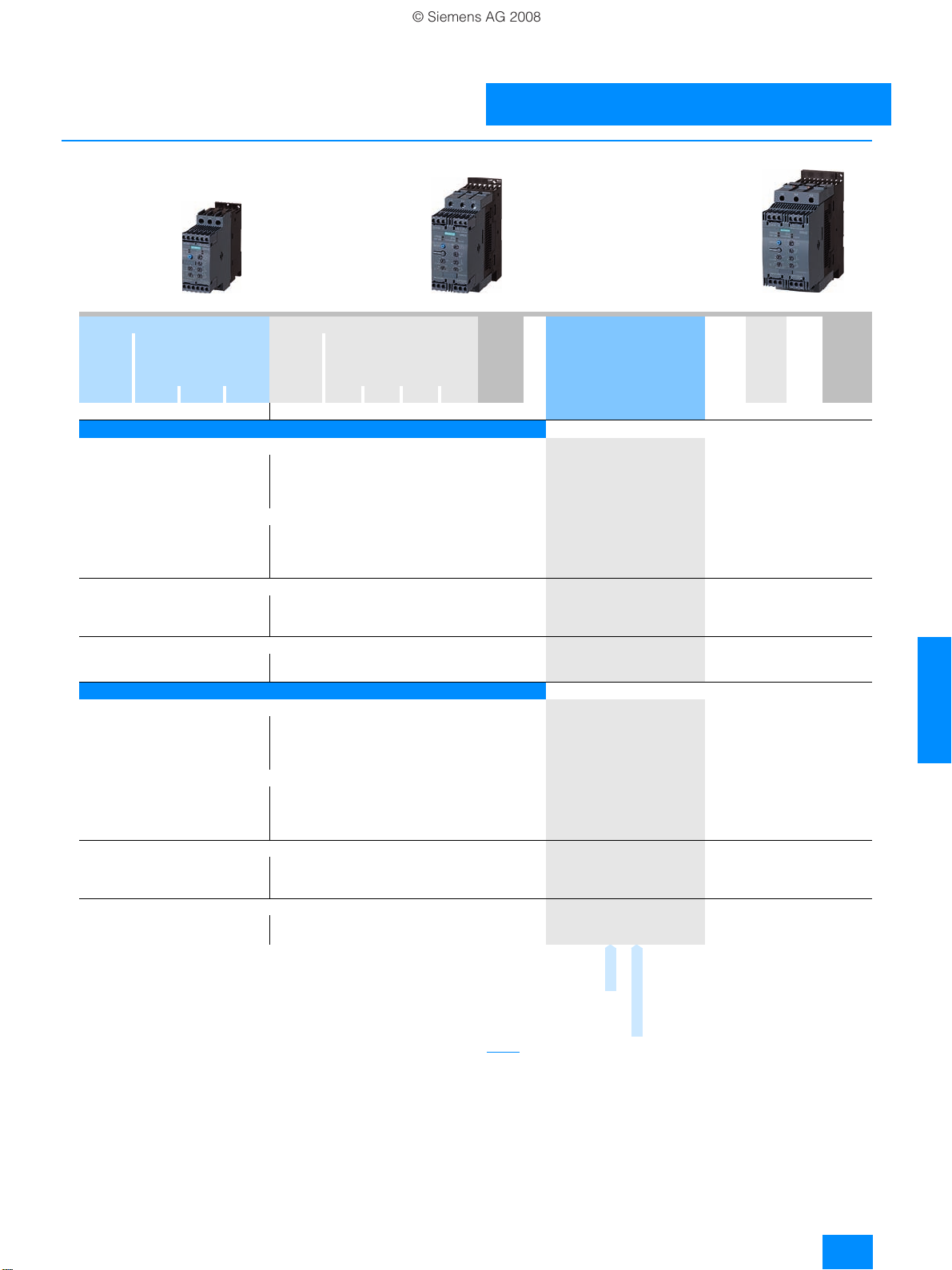
3RW40 28-1BB14 3RW40 38-1BB14 3RW40 47-1BB14
© Siemens AG 2008
Selection and ordering data
3RW Soft Starters
3RW40
for standard applications
Ambient temperature 40 °C Ambient temperature 50 °C Size DT Order No. Price
Rated
operational current I
A kW kW kW A hp hp hp hp kg
Rated power of
three-phase induction
motors for rated
1)
operational voltage U
e
230 V 400 V 500 V 200 V 230 V 460 V 575 V
e
Rated
operational cur-
1)
rent I
e
Rated power of three-phase
induction motors for rated
operational voltage U
e
per PU
PU
PS* PG Weight
(UNIT,
SET, M)
Rated operational voltage Ue 200 ... 480 V2)
• With screw terminals
12.5 3 5.5 -- 11 3 3 7.5 -- S0 } 3RW40 24-1BB@4 1
25 5.5 11 -- 23 5 5 15 -- S0 }
32 7.5 15 -- 29 7.5 7.5 20 -- S0 }
38 11 18.5 -- 34 10 10 25 -- S0 }
• With spring-loaded terminals
12.5 3 5.5 -- 11 3 3 7.5 -- S0 B 3RW40 24-2BB@4 1
25 5.5 11 -- 23 5 5 15 -- S0 B
32 7.5 15 -- 29 7.5 7.5 20 -- S0 B
38 11 18.5 -- 34 10 10 25 -- S0 B
• With screw-type or spring-loaded terminals
45 11 22 -- 42 10 15 30 -- S2 B 3RW40 36-@BB@4 1
63 18.5 30 -- 58 15 20 40 -- S2 B
72 22 37 -- 62 20 20 40 -- S2 B
• With screw-type or spring-loaded terminals
80 22 45 -- 73 20 25 50 -- S3 B 3RW40 46-@BB@4 1
106 30 55 -- 98 30 30 75 -- S3 B
3RW40 26-1BB@4 1
3RW40 27-1BB@4 1
3RW40 28-1BB@4 1
3RW40 26-2BB@4 1
3RW40 27-2BB@4 1
3RW40 28-2BB@4 1
3RW40 37-@BB@4 1
3RW40 38-@BB@4 1
3RW40 47-@BB@4 1
1 unit
1 unit
1 unit
1 unit
1 unit
1 unit
1 unit
1 unit
1 unit
1 unit
1 unit
1 unit
1 unit
131 0.770
131 0.770
131 0.770
131 0.770
131 0.770
131 0.770
131 0.770
131 0.770
131 1.350
131 1.350
131 1.350
131 1.900
131 1.900
Rated operational voltage Ue 400 ... 600 V
• With screw terminals
12.5 -- 5.5 7.5 11 -- -- 7.5 10 S0 B 3RW40 24-1BB@5 1
25 -- 11 15 23 -- -- 15 20 S0 B
32 -- 15 18.5 29 -- -- 20 25 S0 B
38 -- 18.5 22 34 -- -- 25 30 S0 B
• With spring-loaded terminals
12.5 -- 5.5 7.5 11 -- -- 7.5 10 S0 B 3RW40 24-2BB@5 1
25 -- 11 15 23 -- -- 15 20 S0 B
32 -- 15 18.5 29 -- -- 20 25 S0 B
38 -- 18.5 22 34 -- -- 25 30 S0 B
• With screw-type or spring-loaded terminals
45 -- 22 30 42 -- -- 30 40 S2 B 3RW40 36-@BB@5 1
63 -- 30 37 58 -- -- 40 50 S2 B
72 -- 37 45 62 -- -- 40 60 S2 B
• With screw-type or spring-loaded terminals
80 -- 45 55 73 -- -- 50 60 S3 B 3RW40 46-@BB@5 1
106 -- 55 75 98 -- -- 75 75 S3 B
Order No. supplement for connection types
• With screw terminals 1
• With spring-loaded terminals
Order No. supplement for rated control supply voltage U
•24VAC/DC 0
• 110 ... 230 V AC/DC 1
1)
Stand-alone installation without auxiliary fan.
2)
Soft starter with screw terminals: delivery time class } (preferred type).
3)
Main circuit connection: screw terminals.
3)
s
Note:
Selection of the soft starter depends on the rated motor current.
The SIRIUS 3RW40 solid-state soft starters are designed for
easy starting conditions. J
deviating conditions or increased switching frequency, it may be
3RW40 26-1BB@5 1
3RW40 27-1BB@5 1
3RW40 28-1BB@5 1
3RW40 26-2BB@5 1
3RW40 27-2BB@5 1
3RW40 28-2BB@5 1
3RW40 37-@BB@5 1
3RW40 38-@BB@5 1
3RW40 47-@BB@5 1
2
<10xJ
Load
necessary to choose a larger device. Siemens
use of the selection and simulation program
1 unit
1 unit
1 unit
1 unit
1 unit
1 unit
1 unit
1 unit
1 unit
1 unit
1 unit
1 unit
1 unit
. In the event of
Motor
recommends the
Win-Soft Starter.
131 0.770
131 0.770
131 0.770
131 0.770
131 0.770
131 0.770
131 0.770
131 0.770
131 1.350
131 1.350
131 1.350
131 1.900
131 1.900
For information about rated currents for ambient temperatures
> 40 °C, see technical specifications.
per PU
approx.
* You can order this quantity or a multiple thereof.
Siemens LV 1 N SIRIUS Soft Starters · 01/2008
6/7
Page 14
3RW Soft Starters
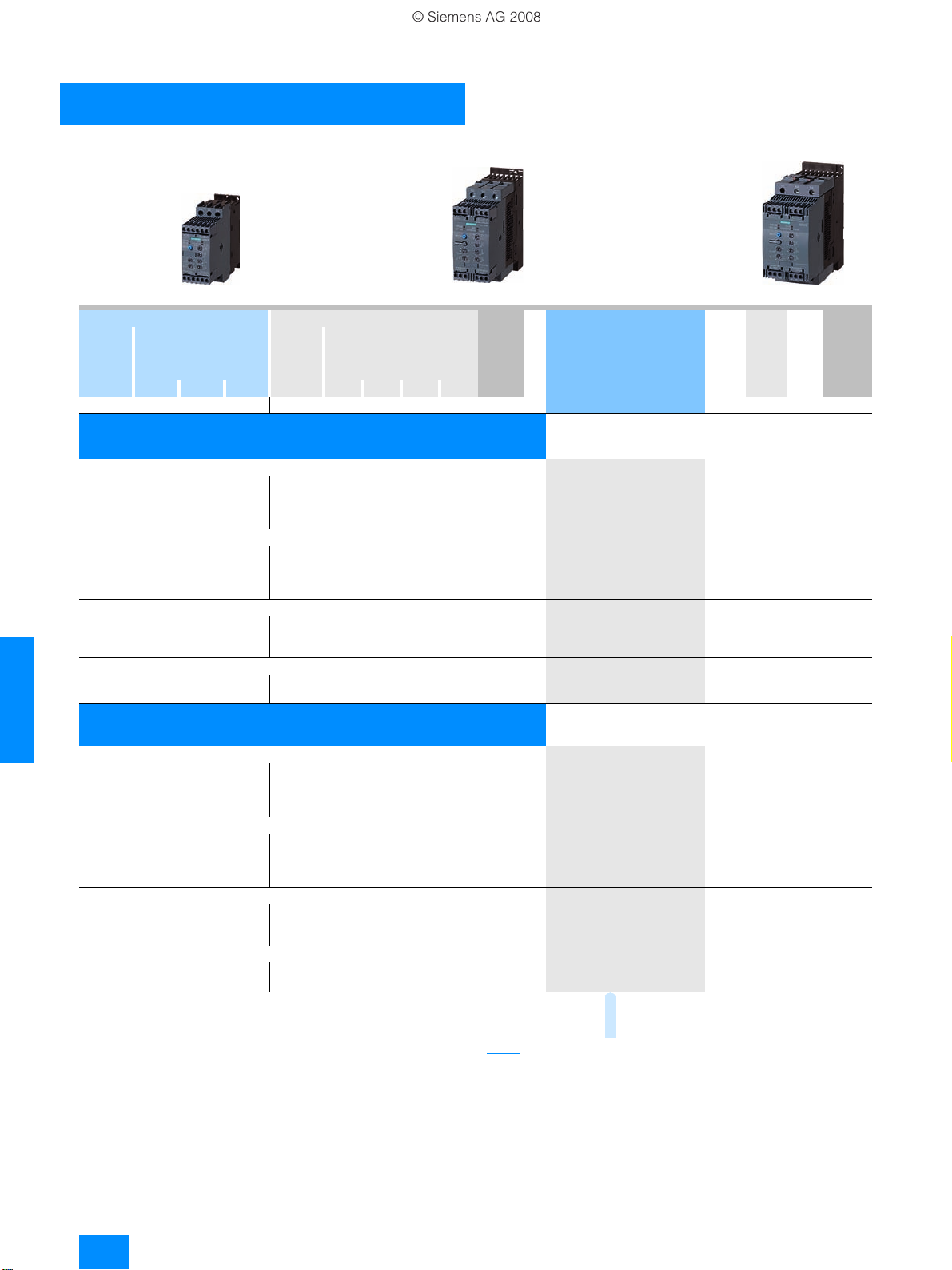
3RW40 28-1TB04 3RW40 38-1TB04 3RW40 47-1TB04
© Siemens AG 2008
3RW40
for standard applications
Ambient temperature 40 °C Ambient temperature 50 °C Size DT Order No. Price
Rated
operational current I
A kW kW kW A hp hp hp hp kg
Rated power of
three-phase induction
motors for rated
1)
operational voltage U
e
230 V 400 V 500 V 200 V 230 V 460 V 575 V
e
Rated
operational cur-
1)
rent I
e
Rated power of three-phase
induction motors for rated
operational voltage U
e
per PU
PU
PS* PG Weight
(UNIT,
SET, M)
per PU
approx.
Rated operational voltage Ue 200 ... 480 V2),
with thermistor motor protection,
rated control supply voltage U
• With screw terminals
12.5 3 5.5 -- 11 3 3 7.5 -- S0 } 3RW40 24-1TB04 1
25 5.5 11 -- 23 5 5 15 -- S0 }
32 7.5 15 -- 29 7.5 7.5 20 -- S0 }
38 11 18.5 -- 34 10 10 25 -- S0 }
• With spring-loaded terminals
12.5 3 5.5 -- 11 3 3 7.5 -- S0 B 3RW40 24-2TB04 1
25 5.5 11 -- 23 5 5 15 -- S0 B
32 7.5 15 -- 29 7.5 7.5 20 -- S0 B
38 11 18.5 -- 34 10 10 25 -- S0 B
• With screw-type or spring-loaded terminals
45 11 22 -- 42 10 15 30 -- S2 B 3RW40 36-@TB04 1
63 18.5 30 -- 58 15 20 40 -- S2 B
72 22 37 -- 62 20 20 40 -- S2 B
• With screw-type or spring-loaded terminals
80 22 45 -- 73 20 25 50 -- S3 B 3RW40 46-@TB04 1
6
106 30 55 -- 98 30 30 75 -- S3 B
Rated operational voltage Ue 400 ... 600 V,
24 V AC/DC
s
3RW40 26-1TB04 1
3RW40 27-1TB04 1
3RW40 28-1TB04 1
3RW40 26-2TB04 1
3RW40 27-2TB04 1
3RW40 28-2TB04 1
3RW40 37-@TB04 1
3RW40 38-@TB04 1
3RW40 47-@TB04 1
1 unit
1 unit
1 unit
1 unit
1 unit
1 unit
1 unit
1 unit
1 unit
1 unit
1 unit
1 unit
1 unit
131 0.770
131 0.770
131 0.770
131 0.770
131 0.770
131 0.770
131 0.770
131 0.770
131 1.350
131 1.350
131 1.350
131 1.900
131 1.900
with thermistor motor protection,
3)
24 V AC/DC
s
1 unit
3RW40 26-1TB05 1
3RW40 27-1TB05 1
3RW40 28-1TB05 1
3RW40 26-2TB05 1
3RW40 27-2TB05 1
3RW40 28-2TB05 1
3RW40 37-@TB05 1
3RW40 38-@TB05 1
3RW40 47-@TB05 1
2
1 unit
1 unit
1 unit
1 unit
1 unit
1 unit
1 unit
1 unit
1 unit
1 unit
1 unit
1 unit
131 0.770
131 0.770
131 0.770
131 0.770
131 0.770
131 0.770
131 0.770
131 0.770
131 1.350
131 1.350
131 1.350
131 1.900
131 1.900
Note:
Selection of the soft starter depends on the rated motor current.
The SIRIUS 3RW40 solid-state soft starters are designed for
easy starting conditions. J
deviating conditions or increased switching frequency, it may be
necessary to choose a larger device. Siemens
use of the selection and simulation program
Load
<10xJ
. In the event of
Motor
recommends the
Win-Soft Starter.
rated control supply voltage U
• With screw terminals
12.5 -- 5.5 7.5 11 -- -- 7.5 10 S0 B 3RW40 24-1TB05 1
25 -- 11 15 23 -- -- 15 20 S0 B
32 -- 15 18.5 29 -- -- 20 25 S0 B
38 -- 18.5 22 34 -- -- 25 30 S0 B
• With spring-loaded terminals
12.5 -- 5.5 7.5 11 -- -- 7.5 10 S0 B 3RW40 24-2TB05 1
25 -- 11 15 23 -- -- 15 20 S0 B
32 -- 15 18.5 29 -- -- 20 25 S0 B
38 -- 18.5 22 34 -- -- 25 30 S0 B
• With screw-type or spring-loaded terminals
45 -- 22 30 42 -- -- 30 40 S2 B 3RW40 36-@TB05 1
63 -- 30 37 58 -- -- 40 50 S2 B
72 -- 37 45 62 -- -- 40 60 S2 B
• With screw-type or spring-loaded terminals
80 -- 45 55 73 -- -- 50 60 S3 B 3RW40 46-@TB05 1
106 -- 55 75 98 -- -- 75 75 S3 B
Order No. supplement for connection types
• With screw terminals 1
• With spring-loaded terminals
1)
Stand-alone installation without auxiliary fan.
2)
Soft starter with screw terminals: delivery time class } (preferred type).
3)
Main circuit connection: screw terminals.
For information about rated currents for ambient temperatures
> 40 °C, see technical specifications.
6/8
Siemens LV 1 N SIRIUS Soft Starters · 01/2008
* You can order this quantity or a multiple thereof.
Page 15
3RW Soft Starters
66
3RW40 56-6BB44 3RW40 76-6BB44
© Siemens AG 2008
for standard applications
3RW40
Ambient temperature 40 °C Ambient temperature 50 °C Size DT Order No. Price
Rated
operational current I
A kW kW kW A hp hp hp hp kg
Rated power of
three-phase induction
motors for rated
1)
operational voltage U
e
230 V 400 V 500 V 200 V 230 V 460 V 575 V
e
Rated
operational cur-
1)
rent I
e
Rated power of three-phase
induction motors for rated
operational voltage U
e
per PU
PU
PS* PG Weight
(UNIT,
SET, M)
Rated operational voltage Ue 200 ... 460 V2)
• With screw-type or spring-loaded terminals
134 37 75 -- 117 30 40 75 -- S6 B 3RW40 55-@BB@4 1
162 45 90 -- 145 40 50 100 -- B
• With screw-type or spring-loaded terminals
230 75 132 -- 205 60 75 150 -- S12 B 3RW40 73-@BB@4 1
280 90 160 -- 248 75 100 200 -- B
356 110 200 -- 315 100 125 250 -- B
432 132 250 -- 385 125 150 300 -- B
3RW40 56-@BB@4 1
3RW40 74-@BB@4 1
3RW40 75-@BB@4 1
3RW40 76-@BB@4 1
1 unit
1 unit
1 unit
1 unit
1 unit
1 unit
131 4.900
131 6.900
131 8.900
131 8.900
131 8.900
131 8.900
Rated operational voltage Ue 400 ... 600 V3)
• With screw-type or spring-loaded terminals
134 -- 75 90 117 -- -- 75 100 S6 B 3RW40 55-@BB@5 1
162 -- 90 110 145 -- -- 100 150 B
• With screw-type or spring-loaded terminals
230 -- 132 160 205 -- -- 150 200 S12 B 3RW40 73-@BB@5 1
280 -- 160 200 248 -- -- 200 250 B
356 -- 200 250 315 -- -- 250 300 B
432 -- 250 315 385 -- -- 300 400 B
Order No. supplement for connection types
• With screw terminals 6
• With spring-loaded terminals 2
Order No. supplement for the rated control supply voltage U
• 115 V AC 3
• 230 V AC 4
1)
Stand-alone installation.
2)
Soft starter with screw terminals: delivery time class } (preferred type).
3)
Soft starter with screw terminals: delivery time class A.
4)
Main circuit connection: busbar connection.
5)
Control by way of the internal 24 V DC supply and direct control by means
of PLC possible.
4)
5)
s
3RW40 56-@BB@5 1
3RW40 74-@BB@5 1
3RW40 75-@BB@5 1
3RW40 76-@BB@5 1
1 unit
1 unit
1 unit
1 unit
1 unit
1 unit
131 4.900
131 6.900
131 8.900
131 8.900
131 8.900
131 8.900
Note:
Selection of the soft starter depends on the rated motor current.
The SIRIUS 3RW40 solid-state soft starters are designed for
easy starting conditions. J
deviating conditions or increased switching frequency, it may be
necessary to choose a larger device. Siemens
use of the selection and simulation program
Load
<10xJ
. In the event of
Motor
recommends the
Win-Soft Starter.
For information about rated currents for ambient temperatures
> 40 °C, see technical specifications.
per PU
approx.
* You can order this quantity or a multiple thereof.
Siemens LV 1 N SIRIUS Soft Starters · 01/2008
6/9
Page 16

3RW Soft Starters
© Siemens AG 2008
3RW40
for standard applications
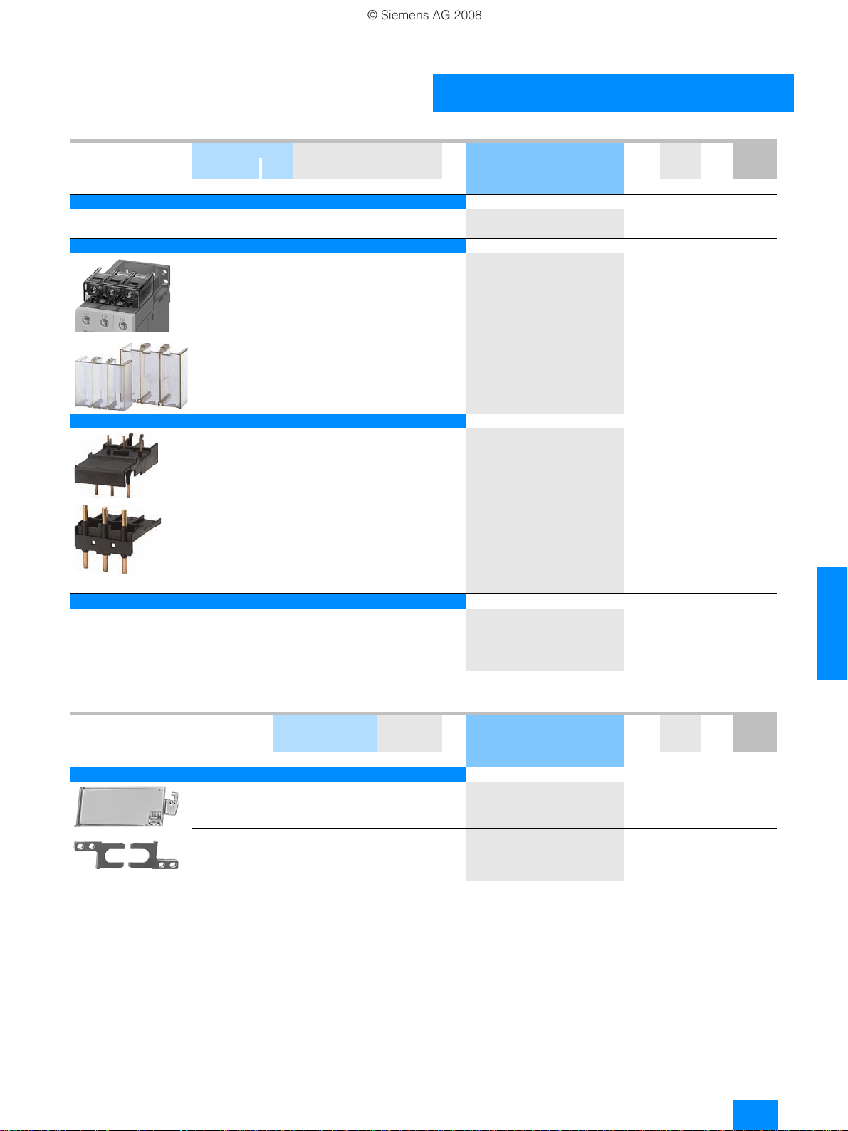
Accessories
For soft starters Versio n DT Order No. Price
Typ e Size
Box terminal blocks for soft starters
For round and ribbon cables
3RW40 5. S6 • Up to 70 mm
3RW40 7. S12 • Up to 240 mm
Auxiliary terminals
Auxiliary terminals, 3-pole
3RW40 4. S3 B3RT19 46-4F 1
Covers for soft starters
Terminal covers for box terminals
Additional touch protection to be fitted at the box terminals
(2 units required per device)
3RW40 3. S2 } 3RT19 36-4EA2 1
3RW40 4. S3 }
3RW40 5. S6 }
3RW40 7. S12 }
Terminal covers for cable lugs and busbar connections
3RW40 4. S3 For complying with the phase
3RW40 5. S6 }
3RW40 7. S12 }
2
• Up to 120 mm
clearances and as touch protection
if box terminal is removed
(2 units required per contactor)
2
2
per PU
} 3RT19 55-4G 1
} 3RT19 56-4G 1
} 3RT19 66-4G 1
3RT19 46-4EA2 1
3RT19 56-4EA2 1
3RT19 66-4EA2 1
3RT19 46-4EA1 1
}
3RT19 56-4EA1 1
3RT19 66-4EA1 1
PU
(UNIT,
SET, M)
PS* PG Weight
1 unit
1 unit
1 unit
1 unit
1 unit
1 unit
1 unit
1 unit
1 unit
1 unit
1 unit
per PU
approx.
kg
101 0.230
101 0.260
101 0.676
101 0.035
101 0.020
101 0.025
101 0.030
101 0.040
101 0.040
101 0.070
101 0.130
Sealing covers
3RW40 2. to
3RW40 4.
3RW40 5. and
3RW40 7.
6
Modules for RESET
1)
Modules for remote RESET, electrical
Operating range 0.85 ... 1.1 x Us,
power consumption AC 80 VA, DC 70 W,
ON period 0.2 s ... 4 s,
switching frequency 60/h
3RW40 5. and
3RW40 7.
Mechanical RESET comprising
3RW40 5. and
3RW40 7.
Cable releases with holder for RESET
For Ø 6.5 mm holes in the control panel;
max. control panel thickness 8 mm
3RW40 5. and
3RW40 7.
S0,
S2,
S3
S6,
S12
S6,
•24...30VAC/DC } 3RU19 00-2AB71 1
S12
• 110 ... 127 V AC/DC }
• 220 ... 250 V AC/DC }
S6,
• Resetting plunger, holder and former } 3RU19 00-1A 1
S12
• Suitable pushbutton IP65, Ø 22 mm,
12 mm stroke
• Extension plunger A
S6,
• Length 400 mm } 3RU19 00-1B 1
S12
• Length 600 mm }
3RW49 00-0PB10 1
}
}
3RW49 00-0PB00 1
3RU19 00-2AF71 1
3RU19 00-2AM71 1
3SB30 00-0EA11 1
B
3SX13 35 1
3RU19 00-1C 1
1 unit
1 unit
1 unit
1 unit
1 unit
1 unit
1 unit
1 unit
1 unit
1 unit
131 0.005
131 0.010
101 0.066
101 0.067
101 0.066
101 0.038
102 0.020
102 0.004
101 0.063
101 0.073
1)
Remote RESET already integrated in the soft starters 3RW40 2. to
3RW40 4..
6/10
Siemens LV 1 N SIRIUS Soft Starters · 01/2008
* You can order this quantity or a multiple thereof.
Page 17

3RW Soft Starters
66
© Siemens AG 2008
for standard applications
3RW40
For soft starters Motor starter protectors
Typ e Size
Size
Link modules to motor starter protectors
3RW40 24,
3RW40 26
3RW40 27,
3RW40 28
3RW40 36 S2 S2 }
3RW40 37,
3RW40 38
3RW40 46,
3RW40 47
S0 S0 } 3RA19 21-1A 1
S2 D
S3 D
S3 S3 }
Fans (to increase switching frequency and for device mounting in
positions different from the normal position)
3RW40 2. S0 } 3RW49 28-8VB00 1
3RW40 3.,
3RW40 4.
S2,
S3
Operating instructions1)
For soft starters
3RW40 2.
3RW40 3.
3RW40 4.
3RW40 5.
1)
The operating instructions are included in the scope of supply.
Spare parts
3RW40 7.S6S12
For soft starters Ver sion DT Order No. Price
Typ e Size Rated control supply
S0
S2
S3
voltage U
s
Fans
Fans
3RW40 5.-.BB3 . S6 115 V AC } 3RW49 36-8VX30 1
3RW40 5.-.BB4 . S6 230 V AC }
3RW40 7.-.BB3 . S12 115 V AC }
3RW40 7.-.BB4 . S12 230 V AC }
DT Order No. Price
3RA19 31-1D 1
3RA19 31-1A 1
3RA19 41-1D 1
3RA19 41-1A 1
3RW49 47-8VB00 1
}
3ZX10 12-0RW40-1AA1
3ZX10 12-0RW40-2DA1
3RW49 36-8VX40 1
3RW49 47-8VX30 1
3RW49 47-8VX40 1
per PU
per PU
PU
PS* PG Weight
(UNIT,
SET, M)
10 units
5 units
5 units
5 units
5 units
1 unit
1 unit
PU
PS* PG Weight
(UNIT,
SET, M)
1 unit
1 unit
1 unit
1 unit
per PU
approx.
kg
101 0.028
101 0.041
101 0.033
101 0.042
101 0.072
131 0.010
131 0.020
per PU
approx.
kg
131 0.300
131 0.300
131 0.500
131 0.500
* You can order this quantity or a multiple thereof.
Siemens LV 1 N SIRIUS Soft Starters · 01/2008
6/11
Page 18

3RW Soft Starters
© Siemens AG 2008
3RW30 for standard applications
■
Function
The space required by the compact SIRIUS 3RW30 soft starter
is often only about one third of that required by a wye-delta
assembly of comparable rating. This not only saves space in the
control cabinet and on the standard mounting rail but also does
away completely with the wiring work needed for wye-delta
starters. This is notable in particular for higher motor ratings
which are only rarely available as fully wired solutions.
At the same time the number of cables from the starter to the
motor is reduced from six to three. Compact dimensions, short
start-up times, easy wiring and fast commissioning make
themselves felt as clear-cut cost advantages.
The bypass contacts
operation by an integrated solid-state arc quenching system.
This prevents damage to the bypass contacts in the event of a
fault, e.g. brief disconnection of the control voltage, mechanical
shocks or life-related component defects on the coil operating
mechanism or main contact spring.
The new series of devices comes with the "polarity balancing"
control method, which is designed to prevent direct current
components in two-phase controlled soft starters. On two-phase
controlled soft starters the current resulting from superimposition
of the two controlled phases flows in the uncontrolled phase.
This results for physical reasons in an asymmetric distribution of
the three phase currents during the motor ramp-up. This
phenomenon cannot be influenced, but in most applications it is
non-critical.
Controlling the power semiconductors results not only in this
asymmetry, however, but also in the previously mentioned direct
current components which can cause severe noise generation
on the motor at starting voltages of less than 50 %. The control
method used for these soft starters eliminates these direct
current components during the ramp-up phase and prevents the
braking torque which they can cause.
of these soft starters are protected during
It creates a motor ramp-up that is uniform in speed, torque and
current rise, thus permitting a particularly gentle, two-phase
starting of the motors. At the same time the acoustic quality of
the starting operation comes close to the quality of a threephase controlled soft starter. This is made possible by the ongoing dynamic harmonizing and balancing of current half-waves
of different polarity during the motor ramp-up. Hence the name
"polarity balancing".
• Soft starting with voltage ramp; the starting voltage setting
range U
from 0 s to 20 s.
is 40 % to 100 % and the ramp time tR can be set
s
• Integrated bypass contact system to minimize power loss
• Setting with two potentiometers
• Simple mounting and start-up
• Mains voltages at 50/60 Hz, 200 to 480 V
• Two control voltage versions 24 V AC/DC and 110 to 230 V AC/DC
• Wide temperature range from -25 °C to +60 °C
• The built-in auxiliary contact ensures user-friendly control and
possible further processing within the system (for status
graphs see page 6/22).
6
■
Technical specifications
Typ e 3RW30 1. , 3RW30 2. 3RW30 3. , 3RW30 4.
Control electronics
Rated values Terminal
Rated control supply voltage A1/A2 V 24 110 ... 230 24 110 ... 230
• Tolerance %
Rated control supply current
• STANDBY mA <50 6 20 <50
• During pick-up mA
•ON mA
Rated frequency Hz
• Tolerance %
Control input
IN ON/OFF
Power consumption with version
•24VDC mA approx. 12
• 110/230 V AC mA
Relay outputs
Output 1 ON 13/14 Operating indication (NO)
Rated operational current A
Protection against overvoltages
Short-circuit protection
Operating indications LED
Off
Start
Bypass
Error signals
• 24 V DC: U < 0.75 x Us or U > 1.25 x U
• 110 ... 230 V AC:U < 0.75 x U
Electrical overloading of bypass
(reset by removing IN command)
Missing mains voltage, phase failure, missing load
Device fault
or U > 1.15 x U
s
s
s
±20 -15/+10 ±20 -15/+10
< 100 15 < 4000 < 500
< 100 15 20 <50
50/60
±10
AC: 3/6; DC: 1.5/3
3 AC-15/AC-14 at 230 V,
1 DC-13 at 24 V
A
Protection by means of varistor through contact
4 A gL/gG operational class;
6 A quick (fuse is not included in scope of supply)
DEVICE
Green Off Green Off
Green Green flashing Green Green flashing
Green Green Green Green
Off Red Off Red
Off Red Off Red
Yellow Red -- --
Green Red Green Red
Red Red Red Red
STATE/BYPASSED/
FAILURE
DEVICE
STATE/BYPASSED/
FAILURE
6/12
Siemens LV 1 N SIRIUS Soft Starters · 01/2008
Page 19

3RW Soft Starters
66
NSB0_01897
10°
10°
10°10°
© Siemens AG 2008
Typ e 3RW30 1. ... 3RW30 4.
Control times and parameters
Control times
Closing delay (with connected control voltage) ms <50
Closing delay (automatic/mains contactor mode) ms < 300
Mains failure bridging time
Control supply voltage ms 50
Mains failure response time
Load current circuit ms 500
Starting parameters
• Starting time s 0...20 7.5
• Starting voltage %
Start-up detection
Operating mode output 13/14
Rising edge at Start command ON
Falling edge at Off command
1)
Mains failure detection only in standby state, not during operation.
Typ e 3RW30 1.-. BB.4 ... 3RW30 4.-.BB .4
Power electronics
Rated operational voltage VAC 200 ... 480
To le ra n ce %
Rated frequency Hz
To le ra n ce %
Continuous duty at 40 °C (% of I
Minimum load (% of I
Maximum cable length between soft starter and motor m
Permissible installation height m
Permissible mounting position
(auxiliary fan not available)
1)
40 ... 100 40
No
-15/+10
50/60
±10
)%115
)%10 (at least 2 A)
e
e
300
5000
(derating from 1000, see characteristic curves); higher on request
3RW30
for standard applications
Factory default
Permissible ambient temperature
Operation °C -25 ... +60; (derating from +40)
Storage °C
Degree of protection
Typ e 3RW30 13 3RW30 14 3RW30 16 3RW30 17 3RW30 18
-40 ... +80
IP20 for 3RW30 1. and 3RW30 2. ;
IP00 for 3RW30 3. and 3RW30 4.
Power electronics
Load rating with rated operational current I
• According to IEC and UL/CSA1), for individual mounting, AC-53a
-at 40°C A 3.6 6.5 9 12.5 17.6
-at 50°C A
-at 60°C A
Power loss
• In operation after completed ramp-up with uninterrupted rated
operational current (40 °C) approx.
• During starting with 300 %
Permissible rated motor current and starts per hour
for normal starting (Class 10)
- rated motor current I
- starts per hour
- rated motor current
- starts per hour
1)
Measurement at 60 °C according to UL/CSA not required.
2)
With 300 % IM.
3)
For intermittent duty S4 with ON period = 30 %, Tu= 40 °C, stand-alone
installation vertical. The quoted switching frequencies do not apply for
automatic mode.
3)
3)
I
(40°C) W 6 13 20 20 29
M
2)
, starting time 3 s A 3.6 6.5 9 12.5 17.6
M
2)
I
, starting time 4 s A 3.6 6.5 9 12.5 17.6
M
e
3.3 6 8 12 17
3 5.5 7 11 14
W 0.25 0.5 1 2 4
1/h 200 87 50 85 62
1/h 150 64 35 62 45
Siemens LV 1 N SIRIUS Soft Starters · 01/2008
6/13
Page 20

3RW Soft Starters
© Siemens AG 2008
3RW30
for standard applications
Typ e 3RW30 26 3RW30 27 3RW30 28
Power electronics
Load rating with rated operational current I
• According to IEC and UL/CSA1), for individual mounting, AC-53a
-at 40°C A 25.3 32.2 38
-at 50°C A
-at 60°C A
Power loss
• In operation after completed ramp-up with uninterrupted rated
operational current (40 °C) approx.
• During starting with 300 %
Permissible rated motor current and starts per hour
for normal starting (Class 10)
- rated motor current I
- starts per hour
- rated motor current
- starts per hour
1)
Measurement at 60 °C according to UL/CSA not required.
2)
With 300 % IM.
3)
For intermittent duty S4 with ON period = 30 %, Tu= 40 °C, stand-alone
installation vertical. The quoted switching frequencies do not apply for
automatic mode.
Typ e 3RW30 36 3RW30 37 3RW30 38 3RW30 46 3RW30 47
3)
3)
I
(40°C) W 47 55 64
M
2)
, starting time 3 s A 25 32 38
M
2)
I
, starting time 4 s A 25 32 38
M
Power electronics
Load rating with rated operational current I
• According to IEC and UL/CSA1), for individual mounting, AC-53a
-at 40°C A 45 65 72 80 106
-at 50°C A
-at 60°C A
Power loss
• In operation after completed ramp-up with uninterrupted rated
operational current (40 °C) approx.
• During starting with 300 %
Permissible rated motor current and starts per hour
for normal starting (Class 10)
- rated motor current I
- starts per hour
- rated motor current
6
- starts per hour
1)
Measurement at 60 °C according to UL/CSA not required.
2)
With 300 % IM.
3)
For intermittent duty S4 with ON period = 70 %, Tu= 40 °C, stand-alone
installation vertical. The quoted switching frequencies do not apply for
automatic mode.
3)
3)
I
(40°C) W 79 111 125 144 192
M
2)
, starting time 3 s A 45 63 72 80 106
M
2)
I
, starting time 4 s A 45 63 72 80 106
M
e
23 29 34
21 26 31
W 8 13 19
1/h 23 23 19
1/h 15 16 12
e
42 58 62.1 73 98
39 53 60 66 90
W 6 12 15 12 21
1/h 38 23 22 22 15
1/h 26 15 15 15 10
6/14
Siemens LV 1 N SIRIUS Soft Starters · 01/2008
Page 21

3RW Soft Starters
66
NSB00479
© Siemens AG 2008
for standard applications
Soft starters Type 3RW30 1. 3RW30 2. 3RW30 3. 3RW30 4.
Conductor cross-sections
Screw terminals Main conductors
Front clamping point
connected
Rear clamping point
connected
Both clamping points
connected
•Solid mm22x(1...2.5);
• Finely stranded with end sleeve mm
• Stranded mm
• AWG cables
- solid or stranded AWG 2x(14...10) 2 x (14 ... 10) 1x(18...2) 1x(10...2/0)
-stranded AWG
•Solid mm
• Finely stranded with end sleeve mm
• Stranded mm
• AWG cables
- solid or stranded AWG -- -- 1x(16...2) 1x(10...2/0)
•Solid mm
• Stranded mm
• Finely stranded with end sleeve mm
• AWG cables
- solid or stranded AWG -- -- 2x(16...2) 2x(10...1/0)
2x(2.5...6)
acc. to IEC 60947
2
2 x (1.5 ... 2.5);
2x(2.5...6)
2
-- -- 1x(0.75...35) 1x(4...70)
1x8 1x8 -- --
2
-- -- 2 x (1.5 ... 16) 2x(2.5...16)
2
-- -- 1 x (1.5 ... 25) 1x(2.5...50)
2
-- -- 1 x (1.5 ... 35) 1x(10...70)
2
-- -- 2 x (1.5 ... 16) 2x(2.5...16)
2
-- -- 2 x (1.5 ... 25) 2x(10...50)
2
-- -- 2 x (1.5 ... 16) 2x(2.5...35)
2 x (1 ... 2.5);
2 x (2.5 ... 6)
acc. to IEC 60947;
max. 1 x 10
2 x (1 ... 2.5);
2x(2.5...6)
2 x (1.5 ... 16) 2x(2.5...16)
1x(0.75...25) 1x(2.5...35)
3RW30
• Tightening torque Nm
Tools
Degree of protection
Spring-loaded terminals Main conductors
•Solid mm21 ... 4 1...10 -- --
• Finely stranded with end sleeve mm
• AWG cables
- solid or stranded (finely stranded) AWG 16 ... 14 16 ... 10 -- --
-stranded AWG
Tools
Degree of protection
Busbar connections Main conductors
• With cable lug according to DIN 46234 or
max. 20 mm wide
-stranded mm2-- -- -- 2x(10...70)
- finely stranded mm
• AWG cables, solid or stranded AWG
Soft starters Type 3RW30 1. ... 3RW30 4 .
2 ... 2.5 2...2.5 4.5 6.5
18 ... 22 18 ... 22 40 58
lb.in
PZ 2 PZ 2 PZ 2 Allen screw 4 mm
IP20 IP20 IP20
2
1 ... 2.5 1 ... 6, end
16 ... 12 1x8 -- -DIN ISO 2380-
1A0; 5 x 3
IP20 IP20 -- --
2
-- -- -- 2x(10...50)
-- -- -- 2x(7...1/0)
sleeves without
plastic collar
DIN ISO 23801A0; 5 x 3
Conductor cross-sections
Auxiliary conductors (1 or 2 conductors can be connected):
Screw terminals
• Solid mm22 x (0.5 ... 2.5)
• Finely stranded with end sleeve mm
•AWG cables
- solid or stranded AWG 2x(20...14)
- finely stranded with end sleeve AWG
• Terminal screws
- tightening torque Nm 0.8 ... 1.2
Spring-loaded terminals
• Solid mm22x(0.25...2.5)
• Finely stranded with end sleeve mm
• AWG cables, solid or stranded AWG
2
lb.in
2
2 x (0.5 ... 1.5)
2x(20...16)
7 ... 10.3
2x(0.25...1.5)
2x(24...14)
(IP00 terminal
compartment)
-- --
-- --
IP20
(IP00 terminal
compartment)
Siemens LV 1 N SIRIUS Soft Starters · 01/2008
6/15
Page 22

3RW Soft Starters
© Siemens AG 2008
3RW30
for standard applications
Typ e 3RW30 03
Control electronics
Rated values
Rated control supply voltage V 24 ... 230 AC/DC
• Tolerance %
Rated control supply current mA
Rated frequency at AC Hz
• Tolerance %
Starting time s
Starting voltage %
Ramp-down time s
Power electronics
Rated operational voltage VAC 200 ... 400
To le ra n ce %
Rated frequency Hz
To le ra n ce %
I
Continuous duty (% of
Minimum load
Maximum conductor length between soft starter and motor m
Degree of protection according to IEC 60529 IP20 (IP00 terminal compartment)
Permissible installation height m
Permissible mounting position
1)
)%100
e
(% of Ie); at 40 °C % 9
± 10
25 ... 4
50/60
± 10
0.1 ... 20 (adjustable)
40 ... 100 (adjustable)
0 ... 20 (adjustable)
± 10
50/60
±10
2)
100
5000
(derating from 1000, see characteristic curves); higher on request
10°
10°
10°10°
NSB0_01897
Permissible ambient temperature
Operation °C -25 ... +60; (derating from +40)
Storage °C
Load rating with rated operational current I
• According to IEC and UL/CSA1), for individual mounting, AC-53a
-at 40°C A 3
-at 50°C A
-at 60°C A
• According to IEC and UL/CSA
6
-at 40°C A 2.6
-at 50°C A
-at 60°C A
Power loss
• In operation after completed ramp-up with uninterrupted rated
operational current (40 °C) approx.
• At utilization of max. switching frequency W
Permissible starts per hour
• For intermittent duty S4, Tu= 40 °C, stand-alone installation vertical 1/h 1500
•ON period=70% %I
1)
, for butt-mounting, AC-53a
e
-40 ... +80
2.6
2.2
2.2
1.8
W 6.5
3
/s 300/0.2
e
Conductor cross-sections
Screw terminals • Main conductors
(1 or 2 conductors connectable)
For standard screwdriver
size 2 and Pozidriv 2
Spring-loaded terminals Main and auxiliary conductors
1)
The rated motor current (specified on the motor's name plate) should at
least amount to the specified percentage of the SIRIUS soft starter unit's
rated operational current I
e
- solid mm²
- finely stranded with end sleeve mm²
- stranded mm²
- AWG cables,
solid or stranded
- terminal screws
- tightening torque Nm
• Auxiliary conductors
- solid mm² 1 x (0.5 ... 4);
- finely stranded with end sleeve mm²
- AWG cables,
solid or stranded
- terminal screws
- tightening torque Nm
• Solid mm22x(0.25...1.5)
• Finely stranded with end sleeve mm
• AWG cables,
solid or stranded
.
1 x (0.5 ... 4);
2 x (0.5 ... 2.5)
1 x (0.5 ... 2.5);
2 x (0.5 ... 1.5)
-2x(20...14)
AWG
M3, PZ2
0.8 ... 1.2
7.1 ... 8.9
lb.in
2 x (0.5 ... 2.5)
1 x (0.5 ... 2.5); 2 x (0.5 ... 1.5)
AWG
2x(20...14)
M3, PZ2
0.8 ... 1.2
lb.in
7...8.9
2
2x(0.25...1)
2
2x(24...16)
mm
2)
If this value is exceeded, problems with line capacities may arise, which
can result in false firing.
6/16
Siemens LV 1 N SIRIUS Soft Starters · 01/2008
Page 23

3RW Soft Starters
66
© Siemens AG 2008
for standard applications
Standard Parameters
Electromagnetic compatibility according to EN 60947-4-2
EMC interference immunity
Electrostatic discharge (ESD) EN 61000-4-2 ±4 kV contact discharge, ±8 kV air discharge
Electromagnetic RF fields
Conducted RF interference
RF voltages and RF currents on cables
•Burst EN 61000-4-4 ±2kV/5kHz
•Surge
EMC interference emission
EMC interference field strength EN 55011 Limit value of Class A at 30 ... 1000 MHz,
Radio interference voltage
Radio interference suppression filters
Degree of noise suppression A (industrial applications) Not required
Degree of noise suppression B (applications for residential areas)
Control voltage
• 230 V AC/DC Not available
•24VAC/DC Not required for 3RW30 1. and 3RW30 2.;
1)
Degree of noise suppression B cannot be obtained through the use of
filters as the strength of the electromagnetic field is not attenuated by the
filter.
EN 61000-4-3 Frequency range: 80 ... 2000 MHz with 80 % at 1 kHz
EN 61000-4-6 Frequency range: 150 kHz ... 80 MHz with 80 % at 1 kHz
EN 61000-4-5 ±1 kV line to line
EN 55011 Limit value of Class A at 0.15 ... 30 MHz,
required for 3RW30 3 . and 3RW30 4. (see table)
Degree of severity 3: 10 V/m
Interference 10 V
±2 kV line to earth
limit value of Class B at 3RW30 2. ; 24 V AC/DC
limit value of Class B for 3RW30 2. ; 24 V AC/DC
1)
3RW30
Soft starter types Rated current
Soft starters Voltage range 200 ... 480 V
A A mm
3RW30 36 45 4EF1512-1AA10 50 16
3RW30 37 63 4EF1512-2AA10 66 25
3RW30 38 72 4EF1512-3AA10 90 25
3RW30 46 80 4EF1512-3AA10 90 25
3RW30 47 106 4EF1512-4AA10 120 50
1)
The radio interference suppression filter is used to remove the conducted
interference from the main circuit. The field-related emissions comply with
degree of noise suppression B.
Recommended filters
Filter types Rated current filters Terminals
1)
2
Siemens LV 1 N SIRIUS Soft Starters · 01/2008
6/17
Page 24

3RW Soft Starters
NSB0_01936
M
3~
Q11
Q21
F1
© Siemens AG 2008
3RW30
for standard applications
Fuse assignment
The type of coordination to which the motor feeder with soft
starter is mounted depends on the application-specific
requirements. Normally, fuseless mounting (combination of
motor starter protector and soft starter) is sufficient.
Fuseless version
Soft starters Motor starter protectors
Rated
Q11 Q1 I
Typ e A Typ e kA A
Type of coordination 1
3RW30 03 3 3RV10 11-1EA10 50 4
3RW30 13 3.6
3RW30 14 6.5
3RW30 16 9
3RW30 17 12.5
3RW30 18 17.6
3RW30 26 25
3RW30 27 32
3RW30 28 38
3RW30 36 45
3RW30 37 63
3RW30 38 72
3RW30 46 80
3RW30 47 106
1)
The rated motor current must be considered when selecting the devices.
6
Fused version (line protection only)
current
Q1
Q11
M
3~
NSB0_01935
1)
400V +10% Rated
q max
2)
3RV10 21-1FA10 10 5
3RV10 21-1HA10 10 8
3RV10 21-1JA10 10 10
3RV10 21-1KA10 10 12.5
3RV10 21-1BA10 10 20
3RV10 31-4DA10 55 25
3RV10 31-4EA10 55 32
3RV10 31-4FA10 55 40
3RV10 31-4GA10 20 45
3RV10 41-4JA10 20 63
3RV10 41-4KA10 20 75
3RV10 41-4LA10 11 90
3RV10 41-4MA10 11 100
If type 2 coordination is to be fulfilled, semiconductor fuses must
be fitted in the motor feeder.
current
2)
The types of coordination are explained in more detail in Catalog LV 1,
"Load Feeders, Motor Starters and Soft Starters" ––> "Fuseless Load Feeders".
Soft starters Line protection, maximum Line contactors
Q11 F1 Q21
Typ e A Typ e A
Type of coordination 11): Iq= 65 kA at 480 V 10 %
3RW30 03
3RW30 13 3.6
3RW30 14 6.5
3RW30 16 9
3RW30 17 12.5
3RW30 18 17.6
3RW30 26 25
3RW30 27 32
3RW30 28 38
3RW30 36 45
3RW30 37 63
3RW30 38 72
3RW30 46 80
3RW30 47 106
1)
The types of coordination are explained in more detail in Catalog LV 1,
"Load Feeders, Motor Starters and Soft Starters" ––> "Fuseless Load
Feeders".
2)
Iq= 50 kA at 400 V.
6/18
Rated
current
2)
3 3NA3 805
3NA3 803-6 10 000 3RT10 15
3NA3 805-6 16 000 3RT10 15
3NA3 807-6 20 000 3RT10 16
3NA3 810-6 25 000 3RT10 24
3NA3 814-6 35 000 3RT10 26
3NA3 822-6 63 00 3RT10 26
3NA3 824-6 80 00 3RT10 34
3NA3 824-6 80 00 3RT10 35
3NA3 130-6 100 1 3RT10 36
3NA3 132-6 125 1 3RT10 44
3NA3 132-6 125 1 3RT10 45
3NA3 136-6 160 1 3RT10 45
3NA3 136-6 160 1 3RT10 46
Rated
current
3)
20 000 3RT10 15
Siemens LV 1 N SIRIUS Soft Starters · 01/2008
Size (optional)
3)
3NA3 805-1 (NH00), 5SB2 61 (DIAZED), 5SE2 201-6 (NEOZED).
Page 25

66
© Siemens AG 2008
Fused version with 3NE1 SITOR fuses (semiconductor and line protection)
Soft starters All-range fuses Line contactors
Rated
Q11 F'1 Q21
Typ e A Ty pe A
Type of coordination 21): Iq= 65 kA at 480 V 10 %
3RW30 03
3RW30 13 3.6
3RW30 14 6.5
3RW30 16 9
3RW30 17 12.5
3RW30 18 17.6
3RW30 26 25
3RW30 27 32
3RW30 28 38
3RW30 36 45
3RW30 37 63
3RW30 38 72
3RW30 46 80
3RW30 47 106
1)
The types of coordination are explained in more detail in Catalog LV 1,
"Load Feeders, Motor Starters and Soft Starters" ––> "Fuseless Load Feeders".
The type of coordination "2" refers only to soft starters, not to any
components in the feeder.
2)
Iq= 50 kA at 400 V.
3)
No SITOR fuse required!
Alternatively: 3NA3 803 (NH00), 5SB2 21 (DIAZED), 5SE2 206 (NEOZED).
current
2)
3 3NE1 813-0
F’1
Q21
Q11
M
3~
NSB0_01937
Rated
current
3)
3NE1 813-0 16 000 3RT10 15
3NE1 813-0 16 000 3RT10 15
3NE1 813-0 16 000 3RT10 16
3NE1 813-0 16 000 3RT10 24
3NE1 814-0 20 000 3RT10 26
3NE1 803-0 35 000 3RT10 26
3NE1 020-2 80 00 3RT10 34
3NE1 020-2 80 00 3RT10 35
3NE1 020-2 80 00 3RT10 36
3NE1 820-0 80 000 3RT10 44
3NE1 820-0 80 000 3RT10 45
3NE1 021-0 100 00 3RT10 45
3NE1 022-0 125 00 3RT10 46
16 000 3RT10 15
Size (optional)
3RW Soft Starters
3RW30
for standard applications
Siemens LV 1 N SIRIUS Soft Starters · 01/2008
6/19
Page 26

3RW30
NSB0_01938
M
3~
Q11
Q1
F3
NSB0_01939
M
3~
Q11
Q21
F1
F3
© Siemens AG 2008
for standard applications
Fused version with 3NE3 SITOR fuses (semiconductor protection by fuse, line and overload protection by motor starter protector;
alternatively, installation with contactor and overload relay possible)
Soft starters Semiconductor fuses, minimum Semiconductor fuses, maximum Semiconductor fuses, minimum
Q11 F3 F3 F3
Typ e A Ty pe A Typ e A Ty pe A
Type of coordination 21): Iq= 65 kA at 480 V 10 %
3RW30 03
3RW30 13 3.6 -- -- -- -- -- -- 3NE4 101 32 0
3RW30 14 6.5
3RW30 16 9
3RW30 17 12.5
3RW30 18 17.6
3RW30 26 25
3RW30 27 32
3RW30 28 38
3RW30 36 45
3RW30 37 63
3RW30 38 72
3RW30 46 80
3RW30 47 106
Soft starters Semiconductor fuses, max. Semiconductor fuses, min. Semiconductor fuses, max. Cylindrical fuses
Q11 F3 F3 F3 F3
Typ e A Ty pe A Ty pe A Typ e A Ty pe A
Type of coordination 21): Iq= 65 kA at 480 V 10 %
6
3RW30 03
3RW30 13 3.6
3RW30 14 6.5
3RW30 16 9
3RW30 17 12.5
3RW30 18 17.6
3RW30 26 25
3RW30 27 32
3RW30 28 38
3RW30 36 45
3RW30 37 63
3RW30 38 72
3RW30 46 80
3RW30 47 106
Soft starters Line contactors Motor starter protectors Line protection, maximum
Q11 Q21 Q1 F1
Typ e A Type A Ty pe A
Type of coordination 21): Iq= 65 kA at 480 V 10 %
3RW30 03
3RW30 13 3.6 3RT10 15 3RV10 21-1FA10
3RW30 14 6.5 3RT10 15 3RV10 21-1HA10
3RW30 16 9 3RT10 16 3RV10 21-1JA10
3RW30 17 12.5 3RT10 24 3RV10 21-1KA10
3RW30 18 17.6 3RT10 26 3RV10 21-1BA10
3RW30 26 25 3RT10 26 3RV10 31-4DA10
3RW30 27 32 3RT10 34 3RV10 31-4EA10
3RW30 28 38 3RT10 35 3RV10 31-4FA10
3RW30 36 45 3RT10 36 3RV10 31-4GA10
3RW30 37 63 3RT10 44 3RV10 41-4JA10
3RW30 38 72 3RT10 45 3RV10 41-4KA10
3RW30 46 80 3RT10 45 3RV10 41-4LA10
3RW30 47 106 3RT10 46 3RV10 41-4MA10
1)
The types of coordination are explained in more detail in Catalog LV 1,
"Load Feeders, Motor Starters and Soft Starters" ––> "Fuseless Load
Feeders". The type of coordination "2" refers only to soft starters, not to any
components in the feeder.
6/20
3RW Soft Starters
Rated
current
2)
3 -- -- -- -- -- --
-- -- -- -- -- -- 3NE4 101 32 0
-- -- -- -- -- -- 3NE4 101 32 0
-- -- -- -- -- -- 3NE4 101 32 0
-- -- -- 3NE3 221 100 1 3NE4 101 32 0
-- -- -- 3NE3 221 100 1 3NE4 102 40 0
-- -- -- 3NE3 222 125 1 3NE4 118 63 0
-- -- -- 3NE3 222 125 1 3NE4 118 63 0
-- -- -- 3NE3 224 160 1 3NE4 120 80 0
-- -- -- 3NE3 225 200 1 3NE4 121 100 0
3NE3 221 100 1 3NE3 227 250 1 -- -- --
3NE3 222 125 1 3NE3 225 200 1 -- -- -3NE3 224 160 1 3NE3 231 350 1 -- -- --
Rated
current
2)
3 -- -- -- 3NE8 015-1 25 00 3NE8 015-1 25 00 3NC1 010 10
-- -- -- 3NE8 015-1 25 00 3NE8 015-1 25 00 3NC2 220 20
-- -- -- 3NE8 015-1 25 00 3NE8 015-1 25 00 3NC2 220 20
-- -- -- 3NE8 015-1 25 00 3NE8 015-1 25 00 3NC2 220 20
-- -- -- 3NE8 015-1 25 00 3NE8 018-1 63 00 3NC2 250 50
-- -- -- 3NE8 003-1 35 00 3NE8 021-1 100 00 3NC2 263 63
3NE4 117 50 0 3NE8 017-1 50 00 3NE8 021-1 100 00 3NC2 263 63
3NE4 118 63 0 3NE8 018-1 63 00 3NE8 022-1 125 00 3NC2 280 80
3NE4 118 63 0 3NE8 020-1 80 00 3NE8 022-1 125 00 3NC2 280 80
3NE4 120 80 0 3NE8 020-1 80 00 3NE8 024-1 160 00 3NC2 280 80
3NE4 121 100 0 3NE8 021-1 100 00 3NE8 024-1 160 00 -- --
-- -- -- 3NE8 022-1 125 00 3NE8 024-1 160 00 -- --
-- -- -- 3NE8 022-1 125 00 3NE8 024-1 160 00 -- --
-- -- -- 3NE8 024-1 160 00 3NE8 024-1 160 00 -- --
Rated
current
2)
3 3RT10 15 3RV10 11-1EA10 4 3NA3 805
(optional) 400 V +10 % Rated
Siemens LV 1 N SIRIUS Soft Starters · 01/2008
Rated
current
Rated
current
Size Rated
Size Rated
current
current
5 3NA3 803-6 10 000
8 3NA3 805-6 16 000
10 3NA3 807-6 20 000
12.5 3NA3 810-6 25 000
20 3NA3 814-6 35 000
25 3NA3 822-6 63 00
32 3NA3 824-6 80 00
40 3NA3 824-6 80 00
45 3NA3 130-6 100 1
63 3NA3 132-6 125 1
75 3NA3 132-6 125 1
90 3NA3 136-6 160 1
100 3NA3 136-6 160 1
current
Size Rated
2)
Iq= 50 kA at 400 V.
3)
3NA3 805-1 (NH00), 5SB2 61 (DIAZED).
Size Rated
current
Rated
current
3)
20 000
Size Rated
Size
current
Size
current
Page 27

3RW Soft Starters
66
© Siemens AG 2008
for standard applications
■
Characteristic curves
Permissible installation height
105
100
95
e
90
85
80
75
70
0 1000 2000 3000 4000 5000
Operational rated current I in %
At an installation height above 2000 m, the max. permissible operational
voltage is reduced to 460 V.
■
More information
Mounting height in m
Application examples for normal starting (Class 10)
Normal starting Class 10 (up to 20 s with 300 % I
The soft starter rating can be selected to be as high as the rating of the motor used
Application Conveyor belt Roller conveyor Compressor Small fan Pump Hydraulic pump
Starting parameters
• Voltage ramp and current
limiting
-starting voltage % 70 60 50 40 40 40
- starting time s
10 10 20 20 10 10
n motor
),
NSB0_01704
3RW30
Note:
These tables present sample set values and device sizes. They
are intended only for the purposes of information and are not
binding. The set values depend on the application in question
and must be optimized during start-up.
The soft starter dimensions should be checked where necessary
with the Win-Soft Starter software or with the help of Technical
Assistance.
Siemens LV 1 N SIRIUS Soft Starters · 01/2008
6/21
Page 28

3RW Soft Starters
NSB0_01940
T1
L1
T2
L2
T3
L3
© Siemens AG 2008
3RW30
for standard applications
Configuration
The 3RW solid-state motor controllers are designed for easy
starting conditions. In the event of deviating conditions or
increased switching frequency, it may be necessary to choose a
larger device. For accurate dimensioning, use the Win-Soft
Starter selection and simulation program.
If necessary, an overload relay for heavy starting must be
selected where long starting times are involved. PTC sensors are
recommended.
In the motor feeder between the SIRIUS 3RW soft starter and the
motor, no capacitive elements are permitted (e.g. no reactivepower compensation equipment). In addition, neither static
systems for reactive-power compensation nor dynamic PFC
(Power Factor Correction) must be operated in parallel during
starting and ramp-down of the soft starter. This is important to
prevent faults arising on the compensation equipment and/or the
soft starter.
All elements of the main circuit (such as fuses, controls and
overload relays) should be dimensioned for direct starting,
following the local short-circuit conditions. Fuses, controls and
overload relays must be ordered separately. Please observe the
maximum switching frequencies specified in the technical
specifications.
Note:
When induction motors are switched on, voltage drops occur as
a rule on starters of all types (direct starters, wye-delta starters,
soft starters). The infeed transformer must always be
dimensioned such that the voltage dip when starting the motor
remains within the permissible tolerance. If the infeed
transformer is dimensioned with only a small margin, it is best for
the control voltage to be supplied from a separate circuit
(independently of the main voltage) in order to avoid the
potential switching off of the soft starter.
Status graphs
U
U
N
U
S
ON 13/14
t
R on
t
R on
t
NSB0_01941
t
Win-Soft Starter selection and simulation program
With this software, you can simulate and select all Siemens soft
starters, taking into account various parameters such as mains
properties, motor and load data, and special application
requirements.
The software is a valuable tool, which makes complicated,
lengthy manual calculations for determining the required soft
starters superfluous.
You can order the CD-ROM under the following order number:
Order No. E20001-D1020-P302-V2-7400.
You can find more information on the Internet at:
http://www.siemens.com/softstarter
Power electronics schematic circuit diagram
6
A bypass contact system is already integrated in the 3RW30 soft
starter and therefore does not have to be ordered separately.
6/22
Siemens LV 1 N SIRIUS Soft Starters · 01/2008
Page 29

66
■
© Siemens AG 2008
Function
The space required by the compact SIRIUS 3RW40 soft starter
is often only about one third of that required by a wye-delta
assembly of comparable rating. This not only saves space in the
control cabinet and on the standard mounting rail but also does
away completely with the wiring work needed for wye-delta
starters. This is notable in particular for higher motor ratings
which are only rarely available as fully wired solutions.
At the same time the number of cables from the starter to the
motor is reduced from six to three. Compact dimensions, short
start-up times, easy wiring and fast commissioning make
themselves felt as clear-cut cost advantages.
The bypass contacts
operation by an integrated solid-state arc quenching system.
This prevents damage to the bypass contacts in the event of a
fault, e.g. brief disconnection of the control voltage, mechanical
shocks or life-related component defects on the coil operating
mechanism or main contact spring.
The starting current of particularly powerful operating
mechanisms can place an unjustifiable load on the local supply
system. Soft starters reduce this starting current by means of their
voltage ramp. Thanks to the adjustable current limiting
SIRIUS 3RW40 soft starter takes even more pressure off the
supply system. It leaves the set start ramp during the ramp-up –
the ramp gradient is fixed by the starting voltage and the ramp
time – as soon as the selected current limit is reached. From this
moment the voltage of the soft starter is controlled so that the
current supplied to the motor remains constant. This process is
ended either by completion of the motor ramp-up or by tripping
by the intrinsic device protection or the motor overload protection.
As the result of this function the actual motor ramp-up can well
take longer than the ramp time selected on the soft starter.
Thanks to the integrated motor overload protection according to
IEC 60947-4-2 there is no need of an additional overload relay
on the new soft starters. The rated motor current, the setting of
the overload tripping time (Class times) and the reset of the
motor overload protection function can be adjusted easily and
quickly. Using a 4-step rotary potentiometer it is possible to set
different overload tripping times on the soft starter. In addition to
Class 10, 15 and 20 it is also possible to switch off the motor
overload protection if a different motor management control
device is to be used for this function, e.g. with connection to
PROFIBUS.
Device versions with thermistor motor protection evaluation
available up to a rating of 55 kW (at 400 V). A "Thermoclick"
measuring probe can be connected directly, as can a PTC of
type A. Thermal overloading of the motor, open-circuits and
short-circuits in the sensor circuit all result in the direct
disconnection of the soft starter. And if ever the soft starter trips,
various reset options are available the same as with intrinsic
device protection and motor load protection: manually with the
reset button, automatically or remotely through brief disconnection
of the control voltage.
The new series of devices comes with the "polarity balancing"
control method, which is designed to prevent direct current
components in two-phase controlled soft starters. On two-phase
controlled soft starters the current resulting from superimposition
of the two controlled phases flows in the uncontrolled phase.
This results for physical reasons in an asymmetric distribution of
the three phase currents during the motor ramp-up. This
phenomenon cannot be influenced, but in most applications it is
non-critical.
of these soft starters are protected during
, the
are
3RW Soft Starters
for standard applications
Controlling the power semiconductors results not only in this
asymmetry, however, but also in the previously mentioned direct
current components which can cause severe noise generation
on the motor at starting voltages of less than 50 %.
The control method used for these soft starters eliminates these
direct current components during the ramp-up phase and
prevents the braking torque which they can cause. It creates a
motor ramp-up that is uniform in speed, torque and current rise,
thus permitting a particularly gentle, two-phase starting of the
motors. At the same time the acoustic quality of the starting
operation comes close to the quality of a three-phase controlled
soft starter. This is made possible by the on-going dynamic
harmonizing and balancing of current half-waves of different
polarity during the motor ramp-up. Hence the name "polarity
balancing".
As an option the thyristors can also be protected by SITOR
semiconductor fuses from short-circuiting so that the soft starter
is still functional after a short-circuit (coordination type 2). Three
LEDs are used to indicate the operating state as well as possible
errors, e.g. non-permissible tripping time (CLASS setting),
mains or phase failure, missing load, thermal overloading or
device faults.
• Soft starting with voltage ramp; the starting voltage setting
range U
0 to 20 s.
• Smooth ramp-down with voltage ramp; the running down time
t
off
• Solid-state motor overload and intrinsic device protection
• Optional thermistor motor protection (up to size S3)
• Remote reset (integrated up to size S3, optional for size S6 and
larger)
• Adjustable current limiting
• Integrated bypass contact system to minimize power loss
• Setting with potentiometers
• Simple mounting and start-up
• Integrated status monitoring and fault monitoring
• Mains voltages 50/60 Hz, 200 ... 600 V
• Various control voltage versions
- sizes S0 to S3:
- sizes S6 to S12:
• Wide temperature range from -25 to +60 °C
• Built-in auxiliary contacts ensure user-friendly control and
possible further processing within the system (for status
graphs see page 6/36)
is 40 to 100 % and the ramp time tR can be set from
s
can be set between 0 s to 20 s.
24 V AC/DC and
110 ... 230 V AC/DC
115 V AC and 230 V AC. Control by way of the internal
24 V DC supply and direct control by means of PLC are
possible.
3RW40
Siemens LV 1 N SIRIUS Soft Starters · 01/2008
6/23
Page 30

3RW Soft Starters
© Siemens AG 2008
3RW40
for standard applications
■
Technical specifications
Typ e 3RW40 2. 3RW40 3., 3RW40 4.
Control electronics
Rated values Terminal
Rated control supply voltage A1/A2 V 24 110 ... 230 24 110 ... 230
• Tolerance %
Rated control supply current
• STANDBY mA < 150 <50 <200 <50
• During pick-up mA
• ON without fan mA
• ON with fan mA
Rated frequency Hz
• Tolerance %
Control inputs
IN ON/OFF
Rated operational current
•AC mA Approx. 12 3/6 Approx. 12 3/6
•DC mA
Relay outputs
Output 1 ON/RUN mode
Output 2 BYPASSED 23/24
Output 3 OVERLOAD/FAILURE 95/96/98
Rated operational current A
Protection against overvoltages
Short-circuit protection
1)
Factory default: ON mode.
Typ e 3RW40 5. 3RW40 7.
1)
13/14 Operating indication (NO)
Control electronics
Rated values Terminal
Rated control supply voltage A1/A2 V AC 115 230 115 230
• Tolerance %
Rated control supply current STANDBY mA
Rated control supply current ON
Rated frequency Hz
6
• Tolerance %
Control inputs
IN ON/OFF
Rated operational current mA
Rated operational voltage V DC
Relay outputs
Output 1 ON/RUN mode
Output 2 BYPASSED 23/24
Output 3 OVERLOAD/FAILURE 95/96/98
Rated operational current A
Protection against overvoltages
Short-circuit protection
1)
Values for the coil power consumption at +10 % Un, 50 Hz.
1)
2)
13/14 Operating indication (NO)
±20 -15/+10 ±20 -15/+10
< 200 <100 < 5000 < 1500
< 250 <50 <200 <50
< 300 <70 <250 <70
50/60
±10
Approx. 12 1.5/3 Approx. 12 1.5/3
Bypass indication (NO)
Overload/error indication (NC/NO)
3 AC-15/AC-14 at 230 V,
1 DC-13 at 24 V
A
Protection by means of varistor through contact
4 A gL/gG operational class;
6 A quick (fuse is not included in scope of supply)
-15/+10 -15/+10
15 15
mA 440 200 660 360
50/60 50/60
±10 ±10
Approx. 10 according to DIN 19240
24 from internal supply dc+ or
external DC supply (according to DIN 19240) through terminals and IN
Bypass indication (NO)
Overload/error indication (NC/NO)
3 AC-15/AC-14 at 230 V,
A
1 DC-13 at 24 V
Protection by means of varistor through contact
4 A gL/gG operational class;
6 A quick (fuse is not included in scope of supply)
2)
Factory default: ON mode.
Typ e 3RW40 2., 3RW40 3., 3RW40 4.
Control electronics
Operating indications LEDs DEVICE STATE/BYPASSED/FAILURE OVERLOAD
Off
Start
Bypass
Ramp-down
Alarm signals
I
/class setting not permissible Green Not relevant Red flashing
e
Start inhibited/thyristors too hot
Error signals
•24V: U < 0.75 x Us or U > 1.25 x U
• 110 ... 230 V: U < 0.75 x U
Non-permissible
for edge 0 –> 1 on input IN
Motor protection shut-down (overload thermistor)
Thermistor defective (open-circuit, short-circuit)
Thermal overloading of the thyristors
Missing mains voltage, phase failure, missing load
Device fault
6/24
s
s
I
/Class setting
e
or U > 1.15 x U
s
Siemens LV 1 N SIRIUS Soft Starters · 01/2008
Green Off Off
Green Green flashing Off
Green Green Off
Green Green flashing Off
Yellow flashing Not relevant Off
Off Red Off
Off Red Off
Green Red Red flashing
Green Off Red
Green Off Red flickering
Yellow Red Off
Green Red Off
Red Red Off
Page 31

3RW Soft Starters
66
© Siemens AG 2008
for standard applications
Typ e 3RW40 5. and 3RW40 7.
Control electronics
Operating indications LEDs DEVICE
Off
Start
Bypass
Ramp-down
Alarm signals
I
/class setting not permissible Green Not relevant Not relevant Red flashing
e
Start inhibited/thyristors too hot
Error signals
U < 0.75 x Us or U > 1.15 x U
Non-permissible
for edge 0 –> 1 on input IN
Motor protection shut-down
Thermal overloading of the thyristors
Missing mains voltage, phase failure, missing load
Device fault
Typ e 3RW40 . .
I
/Class setting
e
s
Green Off Off Off
Green Green flashing Off Off
Green Green Off Off
Green Green flashing Off Off
Yellow flashing Not relevant Not relevant Off
Off Off Red Off
Green Off Red Red flashing
Green Off Off Red
Yellow Off Red Off
Green Off Red Off
Red Off Red Off
Protection functions
Motor protection functions
Trips in the event of Thermal overloading of the motor
Trip class to IEC 60947-4-1 Class 10/15/20 10
Phase failure sensitivity %
Overload warning No
Thermistor protection according to IEC 60947-8, type A/IEC 60947-5-1 Ye s
Reset option after tripping Manual/automatic/remote reset2)
Recovery time min 5
Device protection functions
Trips in the event of Thermal overloading of the thyristors or
Reset option after tripping Manual/automatic/remote reset2)
Recovery time
• During overloading of the thyristors s 30
• During overloading of the bypass s 60
>40
1)
(MAN/AUTO/REMOTE
3)
bypass
(MAN/AUTO/REMOTE
Control times and parameters
Control times
Closing delay (with connected control voltage) ms <50
Closing delay (automatic/mains contactor mode) ms <300
Recovery time (closing command in active ramp-down) ms 100
Mains failure bridging time
Control supply voltage ms 50
Mains failure response time
Load current circuit ms 500
Reclosing lockout after overload trip
Motor protection trip min 5
Device protection trip
• During overloading of the thyristors s 30
• During overloading of the bypass s 60
Starting parameters
Starting time s 0...20 7.5
Starting voltage %
Starting current limit
Ramp-down parameters
Ramp-down time s 0...20 0
Reset mode parameters (for motor/device protection shut-down)
Manual reset LEDs Off Off
Automatic reset LEDs
Remote reset (REMOTE)
Start-up detection Ye s
Operating mode output 13/14
Rising edge at Start command
Falling edge at Off command ON ON
1)
Optional up to size S3 (device variant).
2)
Integrated remote reset (REMOTE) available only for 3RW40 2. to
3RW40 4.; remote reset with accessory module 3RU19 available
for 3RW40 5. and 3RW40 7..
3)
Bypass protection up to size S3.
2)
LEDs Green
Ramp-down end
40 ... 100 40
1.3...5xI
Yellow
RUN
STATE/BYPASSED
e
FAILURE OVERLOAD
Factory default
2)
)
2)
)
5xI
e
3RW40
Siemens LV 1 N SIRIUS Soft Starters · 01/2008
6/25
Page 32

3RW Soft Starters
N S B 0 _ 0 0 6 4 9
2 2 , 5 °
2 2 , 5 °
9 0 °
9 0 °
© Siemens AG 2008
3RW40
for standard applications
Typ e 3RW40 2.-. .B.4,
3RW40 3.-. .B.4,
3RW40 4.-. .B.4
3RW40 2. - . .B.5,
3RW40 3. - . .B.5,
3RW40 4. - . .B.5
3RW40 5.-. BB .4,
3RW40 7.-. BB .4
3RW40 5.-. BB .5,
3RW40 7.-. BB .5
Power electronics
Rated operational voltage VAC 200 ... 480 400 ... 600 200 ... 460 400 ... 600
To le ra n ce %
Rated frequency Hz
To le ra n ce %
Continuous duty at 40 °C (% of I
Minimum load (% of minimum selectable rated motor current I
)%115
e
)%20 (at least 2 A)
M
Maximum cable length between soft starter and motor m
Permissible installation height m
Permissible mounting position
• With auxiliary fan (for 3RW40 2. ... 3RW40 4.)
• Without auxiliary fan (for 3RW40 2. ... 3RW40 4.)
Permissible ambient temperature
Operation °C -25 ... +60; (derating from +40)
Storage °C
Degree of protection
Typ e 3RW40 24 3RW40 26 3RW40 27 3RW40 28
-15/+10 -15/+10 -15/+10 -15/+10
50/60
±10
300
5000
(derating from 1000, see characteristic curves); higher on request
10°
10°
10°10°
-- (fan integrated in the soft starter)
NSB0_01897
-40 ... +80
IP20 for 3RW40 2.;
IP00 for 3RW40 3. and 3RW40 4.
IP00
Power electronics
Load rating with rated operational current I
• According to IEC and UL/CSA1), for individual mounting, AC-53a
-at 40°C A 12.5 25.3 32.2 38
-at 50°C A
6
-at 60°C A
Smallest adjustable rated motor current
For the motor overload protection A 5 10 17 23
Power loss
• In operation after completed ramp-up with uninterrupted rated
operational current (40 °C) approx.
• During starting with current limit set to
I
(40°C)
300 %
M
Permissible rated motor current and starts per hour
• For normal starting (Class 10)
- rated motor current I
- starts per hour
- rated motor current
- starts per hour
• For heavy starting (Class 15)
- rated motor current I
- starts per hour
- rated motor current
- starts per hour
• For heavy starting (Class 20)
- rated motor current I
- starts per hour
- rated motor current
- starts per hour
1)
Measurement at 60 °C according to UL/CSA not required.
2)
Current limit on soft starter set to 300 % IM.
3)
For intermittent duty S4 with ON period = 30 %, Tu= 40 °C, stand-alone
installation vertical. The quoted switching frequencies do not apply for
automatic mode.
4)
Maximum adjustable rated motor current IM, dependent on CLASS setting.
2)
, starting time 3 s A 12.5 25 32 38
M
3)
2)4)
I
, starting time 4 s A 12.5 25 32 38
M
3)
2)
, starting time 4.5 s A 11 23 30 34
M
3)
2)4)
I
, starting time 6 s A 11 23 30 34
M
3)
2)
, starting time 6 s A 10 21 27 31
M
3)
2)4)
I
, starting time 8 s A 10 21 27 31
M
3)
e
11 23 29 34
10 21 26 31
I
M
W 2 8 13 19
W
17 47 55 64
1/h 50 23 23 19
1/h 36 15 16 12
1/h 49 21 18 18
1/h 36 14 13 13
1/h 47 21 20 18
1/h 34 15 14 13
6/26
Siemens LV 1 N SIRIUS Soft Starters · 01/2008
Page 33

3RW Soft Starters
66
© Siemens AG 2008
3RW40
for standard applications
Typ e 3RW40 36 3RW40 37 3RW40 38 3RW40 46 3RW40 47
Power electronics
Load rating with rated operational current I
• According to IEC and UL/CSA1), for individual mounting, AC-53a
-at 40°C A 45 63 72 80 106
-at 50°C A
-at 60°C A
Smallest adjustable rated motor current
For the motor overload protection A 23 26 35 43 46
Power loss
• In operation after completed ramp-up with uninterrupted rated
operational current (40 °C) approx.
• During starting with current limit set to
I
(40 °C)
300 %
M
Permissible rated motor current and starts per hour
• For normal starting (Class 10)
- rated motor current I
- starts per hour
- rated motor current
- starts per hour
• For heavy starting (Class 15)
- rated motor current I
- starts per hour
- rated motor current
- starts per hour
• For heavy starting (Class 20)
- rated motor current I
- starts per hour
- rated motor current
- starts per hour
1)
Measurement at 60 °C according to UL/CSA not required.
2)
Current limit on soft starter set to 300 % IM.
3)
For intermittent duty S4 with ON period = 30 %, Tu= 40 °C, stand-alone
installation vertical. The quoted switching frequencies do not apply for
automatic mode.
4)
Maximum adjustable rated motor current IM, dependent on CLASS setting.
2)
, starting time 3 s A 45 63 72 80 106
M
3)
2)4)
I
, starting time 4 s A 45 63 72 80 106
M
3)
2)
, starting time 4.5 s A 42 50 56 70 84
M
3)
2)4)
I
, starting time 6 s A 42 50 56 70 84
M
3)
2)
, starting time 6 s A 38 46 50 64 77
M
3)
2)4)
I
, starting time 8 s A 38 46 50 64 77
M
3)
Typ e 3RW40 55 3RW40 56 3RW40 73 3RW40 74 3RW40 75 3RW40 76
Power electronics
Load rating with rated operational current I
• According to IEC and UL/CSA1), for individual mounting, AC-53a
-at 40°C A 134 162 230 280 356 432
-at 50°C A
-at 60°C A
Smallest adjustable rated motor current
For the motor overload protection A 59 87 80 130 131 207
Power loss
• In operation after completed ramp-up with uninterrupted rated
operational current (40 °C) approx.
• During starting with current limit set to
2)
IM (40°C)
350 %
Permissible rated motor current and starts per hour
• For normal starting (Class 10)
- rated motor current I
- starts per hour
- rated motor current
- starts per hour
• For heavy starting (Class 15)
- rated motor current I
- starts per hour
- rated motor current
- starts per hour
• For heavy starting (Class 20)
- rated motor current I
- starts per hour
- rated motor current
- starts per hour
1)
Measurement at 60 °C according to UL/CSA not required.
2)
Current limit on soft starter set to 350 % IM.
3)
For intermittent duty S4 with ON period = 70 %, Tu= 40 °C, stand-alone
installation vertical. The quoted switching frequencies do not apply for
automatic mode.
4)
Maximum adjustable rated motor current IM, dependent on CLASS setting.
2)
, starting time 10 s A 134 162 230 280 356 432
M
3)
2)4)
I
, starting time 20 s A 134 162 230 280 356 432
M
3)
2)
, starting time 15 s A 134 152 210 250 341 402
M
3)
2)4)
I
, starting time 30 s A 134 152 210 250 341 402
M
3)
2)
, starting time 20 s A 124 142 200 230 311 372
M
3)
2)4)
I
, starting time 40 s A 124 142 200 230 311 372
M
3)
e
42 58 62.1 73 98
39 53 60 66 90
I
M
W 6 12 15 12 21
W
79 111 125 144 192
1/h 38 23 22 22 15
1/h 26 15 15 15 10
1/h 30 34 34 24 23
1/h 21 24 24 16 17
1/h 30 31 34 23 23
1/h 21 22 24 16 16
e
117 145 205 248 315 385
100 125 180 215 280 335
I
M
W 60 75 75 90 125 165
W
1043 1355 2448 3257 3277 3600
1/h 20 8 14 20 16 17
1/h 7 1.4 3 8 5 5
1/h 11 8 11 13 11 12
1/h 1.2 1.7 1 6 2 2
1/h 12 9 10 10 10 10
1/h 2 2 1 5 1 1
Siemens LV 1 N SIRIUS Soft Starters · 01/2008
6/27
Page 34

3RW Soft Starters
NSB00479
© Siemens AG 2008
3RW40
for standard applications
Soft starters Type 3RW40 2. 3RW40 3. 3RW40 4.
Conductor cross-sections
Screw terminals Main conductors
Front clamping point
connected
Rear clamping point
connected
Both clamping points
connected
Spring-loaded terminals Main conductors
6
Busbar connections Main conductors
•Solid mm22 x (1.5 ... 2.5);
• With end sleeve mm
• Stranded mm
• AWG cables
- solid or stranded AWG 2x(14...10) 1x(18...2) 2x(10...1/0)
-stranded AWG
•Solid mm
• With end sleeve mm
• Stranded mm
• AWG cables
- solid or stranded AWG -- 1x(16...2) 2x(10...1/0)
•Solid mm
• With end sleeve mm
• Stranded mm
• AWG cables
- solid or stranded AWG -- 2x(16...2) 1x(10...2/0)
• Tightening torque Nm
Tools
Degree of protection
•Solid mm21 ... 10 --
• Finely stranded with end sleeve mm
• AWG cables
- solid or stranded (finely stranded) AWG 16 ... 10 --
-stranded AWG
Tools
Degree of protection
• With cable lug according to DIN 46234 or
max. 20 mm wide
-stranded mm2-- 2x(10...70)
- finely stranded mm
• AWG cables, solid or stranded AWG
2 x (2.5 ... 6) according
to IEC 60947;
max. 1 x 10
2
2 x (1.5 ... 2.5);
2x(2.5...6)
2
-- 1x(0.75...35) 1 x (4 ... 70)
1x8 -- --
2
-- 2 x (1.5 ... 16) 2 x (2.5 ... 16)
2
-- 1 x (1.5 ... 25) 1 x (2.5 ... 50)
2
-- 1 x (1.5 ... 35) 1x(10...70)
2
-- 2 x (1.5 ... 16) 2 x (2.5 ... 16)
2
-- 2 x (1.5 ... 16) 2 x (2.5 ... 35)
2
-- 2 x (1.5 ... 25) 2x(10...50)
2 ... 2.5 4.5 6.5
lb.in
18 ... 22 40 58
PZ 2 PZ 2 Allen screw 4 mm
IP20 IP20
2
1 ... 6 end sleeves without plastic collar
1x8 -DIN ISO 2380-1A0; 5 x 3 -IP20 --
2
-- 2x(10...50)
-- 2x(7...1/0)
2 x (1.5 ... 16) 2 x (2.5 ... 16)
1x(0.75...25) 1 x (2.5 ... 35)
(IP00 terminal
compartment)
--
IP20
(IP00 terminal
compartment)
6/28
Siemens LV 1 N SIRIUS Soft Starters · 01/2008
Page 35

3RW Soft Starters
66
NSB00479
NSB00479
© Siemens AG 2008
for standard applications
Soft starters Type 3RW40 5. 3RW40 7.
Conductor cross-sections
Screw terminals Main conductors
With box terminal 3RT19 55-4G (55 kW) 3RT19 66-4G
Front clamping point
connected
• Finely stranded with end sleeve mm
• Finely stranded without end sleeve mm
• Stranded mm
• Ribbon cable conductors
(number x width x thickness)
• AWG cables, solid or stranded AWG
2
16 ... 70 70 ... 240
2
16 ... 70 70 ... 240
2
16 ... 70 95 ... 300
Min. 3 x 9 x 0.8
mm
Max. 6 x 15.5 x 0.8
6...2/0 3/0 ... 600 kcmil
Min.6x9x0.8
Max. 20 x 24 x 0.5
3RW40
Rear clamping point
connected
Both clamping points
connected
Screw terminals Main conductors
With box terminal 3RT19 56-4G
Front or rear clamping point
connected
Both clamping points
connected
Screw terminals Main conductors
1)
When connecting cable lugs to DIN 46235, use 3RT19 56-4EA1 terminal
cover for conductor cross-sections from 95 mm² to ensure phase spacing.
Soft starters Type 3RW40 . .
• Finely stranded with end sleeve mm216 ... 70 120 ... 185
• Finely stranded without end sleeve mm
• Stranded mm
• Ribbon cable conductors
(number x width x thickness)
• AWG cables, solid or stranded AWG
• Finely stranded with end sleeve mm2Max. 1x50, 1x70 Min. 2 x 50; max. 2 x 185
• Finely stranded without end sleeve mm
• Stranded mm
• Ribbon cable conductors
(number x width x thickness)
• AWG cables, solid or stranded AWG
• Terminal screws
- tightening torque Nm
• Finely stranded with end sleeve mm216 ... 120
• Finely stranded without end sleeve mm216 ... 120
• Stranded mm216 ... 120
• Ribbon cable conductors
(number x width x thickness)
• AWG cables, solid or stranded AWG 6 ... 250 kcmil
• Finely stranded with end sleeve mm2Max. 1x95, 1x120
• Finely stranded without end sleeve mm2Max. 1x95, 1x120
• Stranded mm2Max. 2 x 120
• Ribbon cable conductors
(number x width x thickness)
• AWG cables, solid or stranded AWG Max. 2 x 3/0
Without box terminal/busbar connection
• Finely stranded with cable lug mm216 ... 95
• Stranded with cable lug mm225 ... 120
• AWG cables, solid or stranded AWG 4 ... 250 kcmil 2/0 ... 500 kcmil
• Connecting bar (max. width) mm
• Terminal screws
- tightening torque Nm
2
16 ... 70 120 ... 185
2
16 ... 70 120 ... 240
Min. 3 x 9 x 0.8
mm
Max. 6 x 15.5 x 0.8
6...2/0 250 ... 500 kcmil
2
Max. 1x50, 1x70 Min. 2 x 50; max. 2 x 185
2
Max. 2 x 70 Max. 2 x 70; max. 2 x 240
Max. 2 x (6 x 15.5 x 0.8) Max.2x(20x24x0.5)
mm
Max. 2 x 1/0 Min. 2 x 2/0 Max. 2 x 500 kcmil
M10 (hexagon socket, A/F4) M12 (hexagon socket, A/F5)
10 ... 12 20 ... 22
lb.in
90 ... 110 180 ... 195
mm Min. 3 x 9 x 0.8
Max. 6 x 15.5 x 0.8
mm Max. 2 x (10 x 15.5 x 0.8)
1)
1)
17 25
M8 x 25 (A/F13) M10 x 30 (A/F17)
10 ... 14 14 ... 24
89 ... 124 124 ... 210
lb.in
2)
When connecting cable lugs to DIN 46234, the 3RT19 66-4EA1 terminal cover must
be used for conductor cross-sections of 240 mm² and more as well as DIN 46235
for conductor cross-sections of 185 mm² and more to keep the phase clearance.
Min.6x9x0.8
Max. 20 x 24 x 0.5
2)
50 ... 240
2)
70 ... 240
Conductor cross-sections
Auxiliary conductors (1 or 2 conductors can be connected):
Screw terminals
• Solid mm22 x (0.5 ... 2.5)
• Finely stranded with end sleeve mm
• AWG cables
- solid or stranded AWG 2x(20...14)
- finely stranded with end sleeve AWG
• Terminal screws
- tightening torque Nm 0.8 ... 1.2
Spring-loaded terminals
• Solid
- 3RW40 2. ... 3RW40 4. mm22x(0.25...2.5)
- 3RW40 5., 3RW40 7. mm
• Finely stranded with end sleeve mm
• AWG cables, solid or stranded AWG
2
2 x (0.5 ... 1.5)
2x(20...16)
7...10.3
lb.in
2
2x(0.25...1.5)
2
2x(0.25...1.5)
2 x (24 ... 14) for 3RW40 2. ... 3RW40 4.;
2 x (24 ... 16) for 3RW40 5. and 3RW40 7.
Siemens LV 1 N SIRIUS Soft Starters · 01/2008
6/29
Page 36

3RW Soft Starters
© Siemens AG 2008
3RW40
for standard applications
Standard Parameters
Electromagnetic compatibility according to EN 60947-4-2
EMC interference immunity
Electrostatic discharge (ESD) EN 61000-4-2 ±4 kV contact discharge, ±8 kV air discharge
Electromagnetic RF fields
Conducted RF interference
RF voltages and RF currents on cables
•Burst EN 61000-4-4 ±2kV/5kHz
•Surge
EMC interference emission
EMC interference field strength EN 55011 Limit value of Class A at 30 ... 1000 MHz,
Radio interference voltage
Radio interference suppression filters
Degree of noise suppression A (industrial applications) Not required
Degree of noise suppression B (applications for residential areas)
Control voltage
• 110 ... 230 V AC/DC Not available
• 115/230 V AC Not available
•24VAC/DC Not required for 3RW40 2. ;
1)
Degree of noise suppression B cannot be obtained through the use of
filters as the strength of the electromagnetic field is not attenuated by the
filter.
Soft starter types Rated current Recommended filters
Soft starters Voltage range 200 ... 480 V
Filter types Rated current filters Terminals
A A mm
3RW40 36 45 4EF1512-1AA10 50 16
3RW40 37 63 4EF1512-2AA10 66 25
3RW40 38 72 4EF1512-3AA10 90 25
6
3RW40 46 80 4EF1512-3AA10 90 25
3RW40 47 106 4EF1512-4AA10 120 50
1)
The radio interference suppression filter is used to remove the conducted
interference from the main circuit. The field-related emissions comply with
degree of noise suppression B.
EN 61000-4-3 Frequency range: 80 ... 1000 MHz with 80 % at 1 kHz
EN 61000-4-6 Frequency range: 150 kHz ... 80 MHz with 80 % at 1 kHz
EN 61000-4-5 ±1 kV line to line
EN 55011 Limit value of Class A at 0.15 ... 30 MHz,
required for 3RW40 3. and 3RW40 4. (see Table)
1)
Degree of severity 3: 10 V/m
Interference 10 V
±2 kV line to earth
limit value of Class B with 3RW40 2. 24 V AC/DC
limit value of Class B with 3RW40 2. 24 V AC/DC
1)
1)
2
6/30
Siemens LV 1 N SIRIUS Soft Starters · 01/2008
Page 37

3RW Soft Starters
66
© Siemens AG 2008
for standard applications
Fuse assignment
The type of coordination to which the motor feeder with soft
starter is mounted depends on the application-specific
requirements. Normally, fuseless mounting (combination of
Fuseless version
Soft starters Motor starter protectors/circuit breakers
Rated
Q11 Q1 Q1 I
Typ e A Typ e Typ e kA A Ty pe kA A
Type of coordination 1
3RW40 24 12.5 3RV1 031-4AA10 3RV1 331-4AC10 55 16 -- -- --
3RW40 26 25
3RW40 27 32
3RW40 28 38
3RW40 36 45
3RW40 37 63
3RW40 38 72
3RW40 46 80
3RW40 47 106
3RW40 55 134
3RW40 56 162
3RW40 73 230
3RW40 74 280
3RW40 75 356
3RW40 76 432
1)
The rated motor current must be considered when selecting the devices.
Fused version (line protection only)
current
Q1
Q11
M
3~
NSB0_01902
400V +10% 400 V +10 % Rated
2)
3RV1 031-4DA10 3RV1 331-4DC10 55 25 -- -- -3RV1 031-4EA10 3RV1 331-4EC10 55 32 -- -- -3RV1 031-4FA10 3RV1 331-4FC10 55 40 -- -- --
3RV1 031-4GA10 3RV1 331-4GC10 20 45 -- -- -3RV1 041-4JA10 3RV1 341-4JC10 20 63 -- -- -3RV1 041-4KA10 3RV1 341-4KC10 20 75 -- -- --
3RV1 041-4LA10 3RV1 341-4LC10 11 90 -- -- -3RV1 041-4MA10 3RV1 341-4MC10 11 100 -- -- --
3VL3 720-2DC36 35 200 3VL3 720-1DC36 12 200
3VL3 720-2DC36 35 200 3VL3 720-1DC36 12 200
3VL4 731-2DC36 65 315 3VL5 731-3DC36 35 315
3VL4 731-2DC36 65 315 3VL5 731-3DC36 35 315
3VL4 740-2DC36 65 400 3VL5 740-3DC36 35 400
3VL5 750-2DC36 65 500 3VL5 750-3DC36 35 500
motor starter protector and soft starter) is sufficient. If type 2
coordination is to be fulfilled, semiconductor fuses must be fitted
in the motor feeder.
1)
current
q max
2)
The types of coordination are explained in more detail in Catalog LV 1,
"Load Feeders, Motor Starters and Soft Starters" ––> "Fuseless Load
Feeders".
575 V +10 % Rated
Q1 I
q max
3RW40
current
F1
Q21
Q11
M
3~
NSB0_01904
Soft starters Line protection, maximum Line contactors
Rated
Q11 F1 Q21
Typ e A Typ e A
Type of coordination 11): Iq= 65 kA at 600 V +5 %
3RW40 24 12.5
3RW40 26 25
3RW40 27 32
3RW40 28 38
3RW40 36 45
3RW40 37 63
3RW40 38 72
3RW40 46 80
3RW40 47 106
3RW40 55 134
3RW40 56 162
3RW40 73 230
3RW40 74 280
3RW40 75 356
3RW40 76 432
1)
The types of coordination are explained in more detail in Catalog LV 1,
"Load Feeders, Motor Starters and Soft Starters" ––> "Fuseless Load
Feeders".
current
3NA3 820-6 50 00 3RT10 24
3NA3 822-6 63 00 3RT10 26
3NA3 824-6 80 00 3RT10 34
3NA3 824-6 80 00 3RT10 35
3NA3 130-6 100 1 3RT10 36
3NA3 132-6 125 1 3RT10 44
3NA3 132-6 125 1 3RT10 45
3NA3 136-6 160 1 3RT10 45
3NA3 136-6 160 1 3RT10 46
3NA3 244-6 250 2 3RT10 55-6A.36
3NA3 244-6 250 2 3RT10 56-6A.36
2 x 3NA3 354-6 2 x 355 3 3RT10 65-6A.36
2 x 3NA3 354-6 2 x 355 3 3RT10 66-6A.36
2 x 3NA3 365-6 2 x 500 3 3RT10 75-6A.36
2 x 3NA3 365-6 2 x 500 3 3RT10 76-6A.36
Rated
current
Size (optional)
Siemens LV 1 N SIRIUS Soft Starters · 01/2008
6/31
Page 38

3RW Soft Starters
© Siemens AG 2008
3RW40
for standard applications
Fused version with 3NE1 SITOR fuses (semiconductor and line protection)
Soft starters All-range fuses Line contactors
Rated
Q11 F'1 Q21
Typ e A Typ e A
Type of coordination 21): Iq= 65 kA at 600 V +5 %
3RW40 24 12.5
3RW40 26 25
3RW40 27 32
3RW40 28 38
3RW40 36 45
3RW40 37 63
3RW40 38 72
3RW40 46 80
3RW40 47 106
3RW40 55 134
3RW40 56 162
3RW40 73 230
3RW40 74 280
3RW40 75 356
3RW40 76 432
1)
The types of coordination are explained in more detail in Catalog LV 1,
"Load Feeders, Motor Starters and Soft Starters" ––> "Fuseless Load
Feeders".
The type of coordination "2" refers only to soft starters, not to any
components in the feeder.
current
F’1
Q21
Q11
M
3~
NSB0_01905
Rated
current
3NE1 814-0 20 000 3RT10 24
3NE1 803-0 35 000 3RT10 26
3NE1 020-2 80 00 3RT10 34
3NE1 020-2 80 00 3RT10 35
3NE1 020-2 80 00 3RT10 36
3NE1 820-0 80 000 3RT10 44
3NE1 820-0 80 000 3RT10 45
3NE1 021-0 100 00 3RT10 45
3NE1 022-0 125 00 3RT10 46
3NE1 227-2 250 1 3RT10 55-6A.36
3NE1 227-2 250 1 3RT10 56-6A.36
3NE1 331-2 350 2 3RT10 65-6A.36
3NE1 333-2 450 2 3RT10 66-6A.36
3NE1 334-2 500 2 3RT10 75-6A.36
3NE1 435-2 560 3 3RT10 76-6A.36
Size (optional)
6
6/32
Siemens LV 1 N SIRIUS Soft Starters · 01/2008
Page 39

66
NSB0_01903
M
3~
Q11
Q1
F3
NSB0_01906
M
3~
Q11
Q21
F1
F3
© Siemens AG 2008
3RW Soft Starters
3RW40
for standard applications
Fused version with 3NE3 SITOR fuses (semiconductor protection by fuse, line and overload protection by motor starter protector;
alternatively, installation with contactor and overload relay possible)
Soft starters Semiconductor fuses, minimum Semiconductor fuses, maximum Semiconductor fuses, minimum
Rated
Q11 F3 F3 F3
Typ e A Typ e A Ty pe A Typ e A
Type of coordination "2"1): Iq= 65 kA at 600 V +5 %
3RW40 24 12.5
3RW40 26 25
3RW40 27 32
3RW40 28 38
3RW40 36 45
3RW40 37 63
3RW40 38 72
3RW40 46 80
3RW40 47 106
3RW40 55 134
3RW40 56 162
3RW40 73 230
3RW40 74 280
3RW40 75 356
3RW40 76 432
Soft starters Semiconductor fuses max. Semiconductor fuses min. Semiconductor fuses max. Cylindrical fuses
Q11 F3 F3 F3 F3
Typ e A Typ e A Typ e A Ty pe A Typ e A
Type of coordination "2"1): Iq= 65 kA at 600 V +5 %
3RW40 24 12.5
3RW40 26 25
3RW40 27 32
3RW40 28 38
3RW40 36 45
3RW40 37 63
3RW40 38 72
3RW40 46 80
3RW40 47 106
3RW40 55 134
3RW40 56 162
3RW40 73 230
3RW40 74 280
3RW40 75 356
3RW40 76 432
Soft starters Line contactors Motor starter protectors/circuit breakers Line protection, maximum
Q11 Q21 Q1 Q1 F1
Typ e A Typ e A Ty pe A Ty pe A
Type of coordination "2"1): Iq= 65 kA at 600 V +5 %
3RW40 24 12.5 3RT10 24 3RV1 031-4AA10 55
3RW40 26 25 3RT10 26 3RV1 031-4DA10 55
3RW40 27 32 3RT10 34 3RV1 031-4EA10 55
3RW40 28 38 3RT10 35 3RV1 031-4FA10 55
3RW40 36 45 3RT10 36 3RV1 031-4GA10 20
3RW40 37 63 3RT10 44 3RV1 041-4JA10 20
3RW40 38 72 3RT10 45 3RV1 041-4KA10 20
3RW40 46 80 3RT10 45 3RV1 041-4LA10 11
3RW40 47 106 3RT10 46 3RV1 041-4MA10 11
3RW40 55 134 3RT10 55-6A.36
3RW40 56 162 3RT10 56-6A.36
3RW40 73 230 3RT10 65-6A.36
3RW40 74 280 3RT10 66-6A.36
3RW40 75 356 3RT10 75-6A.36
3RW40 76 432 3RT10 76-6A.36
1)
The types of coordination are explained in more detail in Catalog LV 1, "Load Feeders, Motor Starters and Soft Starters" ––> "Fuseless Load Feeders".
The type of coordination "2" refers only to soft starters, not to any components in the feeder.
current
Rated
current
Rated
current
-- -- -- -- -- -- 3NE4 101 32 0
-- -- -- 3NE3 221 100 1 3NE4 102 40 0
-- -- -- 3NE3 224 160 1 3NE4 118 63 0
-- -- -- 3NE3 224 160 1 3NE4 118 63 0
-- -- -- 3NE3 224 160 1 3NE4 120 80 0
-- -- -- 3NE3 225 200 1 3NE4 121 100 0
3NE3 221 100 1 3NE3 227 250 1 -- -- --
3NE3 222 125 1 3NE3 225 200 1 -- -- -3NE3 224 160 1 3NE3 231 350 1 -- -- --
3NE3 227 250 1 3NE3 335 560 2 -- -- -3NE3 227 250 1 3NE3 335 560 2 -- -- --
3NE3 232-0B 400 1 3NE3 333 450 2 -- -- -3NE3 233 450 1 3NE3 336 630 2 -- -- -3NE3 335 560 2 3NE3 336 630 2 -- -- -3NE3 337-8 710 2 3NE3 340-8 900 2 -- -- --
3NE4 117 50 0 3NE8 015-1 25 00 3NE8 017-1 50 00 3NC2 240 40
3NE4 117 50 0 3NE8 017-1 50 00 3NE8 021-1 100 00 3NC2 263 63
3NE4 118 63 0 3NE8 018-1 63 00 3NE8 022-1 125 00 3NC2 280 80
3NE4 118 63 0 3NE8 020-1 80 00 3NE8 024-1 160 00 3NC2 280 80
3NE4 120 80 0 3NE8 020-1 80 00 3NE8 024-1 160 00 3NC2 280 80
3NE4 121 100 0 3NE8 021-1 100 00 3NE8 024-1 160 00 -- --
-- -- -- 3NE8 022-1 125 00 3NE8 024-1 160 00 -- --
-- -- -- 3NE8 022-1 125 00 3NE8 024-1 160 00 -- --
-- -- -- 3NE8 024-1 160 00 3NE8 024-1 160 00 -- --
-- -- -- -- -- -- -- -- -- -- --
-- -- -- -- -- -- -- -- -- -- --
-- -- -- -- -- -- -- -- -- -- --
-- -- -- -- -- -- -- -- -- -- --
-- -- -- -- -- -- -- -- -- -- --
-- -- -- -- -- -- -- -- -- -- --
(optional) 400 V +10 % Rated
Rated
current
Rated
current
3VL3 720-1DC36 200 3VL3 720-1DC36 200 3NA3 244-6 250 2
3VL3 720-1DC36 200 3VL3 720-1DC36 200 3NA3 244-6 250 2
3VL4 731-1DC36 315 3VL5 731-1DC36 315 2 x 3NA3 354-6 2 x 355 3
3VL4 731-1DC36 315 3VL5 731-1DC36 315 2 x 3NA3 354-6 2 x 355 3
3VL4 740-1DC36 400 3VL5 740-1DC36 400 2 x 3NA3 365-6 2 x 500 3
3VL5 750-1DC36 500 3VL5 750-1DC36 500 2 x 3NA3 365-6 2 x 500 3
Size Rated
Size Rated
current
current
current
Size Rated
575 V +10 % Rated
-- -- 3NA3 820-6 50 00
-- -- 3NA3 822-6 63 00
-- -- 3NA3 824-6 80 00
-- -- 3NA3 824-6 80 00
-- -- 3NA3 130-6 100 1
-- -- 3NA3 132-6 125 1
-- -- 3NA3 132-6 125 1
-- -- 3NA3 136-6 160 1
-- -- 3NA3 136-6 160 1
Size Rated
current
current
current
Size Rated
Rated
current
Size
current
Size
Siemens LV 1 N SIRIUS Soft Starters · 01/2008
6/33
Page 40

3RW Soft Starters
10
1
10
2
10
3
2
4
6
2
4
6
e
x
246
10
NSB0_01488a
1
Class 10 Class 15
Class 20
[s]
Tripping time
© Siemens AG 2008
3RW40
for standard applications
■
Characteristic curves
Motor protection tripping characteristics
for 3RW40 (with symmetry)
Motor protection tripping characteristics
for 3RW40 (with asymmetry)
3
10
[s]
Tripping Time
10
10
6
4
2
2
6
4
2
1
0,1
Class 10 Class 15
1,0
x
Class 20
NSB0_01705
10
e
Permissible installation height
105
100
95
6
e
90
85
80
75
70
0 1000 2000 3000 4000 5000
Operational rated current I in %
At an installation height above 2000 m, the max. permissible operational
voltage is reduced to 460 V.
Mounting height in m
NSB0_01704
6/34
Siemens LV 1 N SIRIUS Soft Starters · 01/2008
Page 41

3RW Soft Starters
66
© Siemens AG 2008
for standard applications
■
More information
Application examples for normal starting (Class 10)
Normal starting Class 10 (up to 20 s with 350 % I
The soft starter rating can be selected to be as high as the rating of the motor used.
Application Conveyor belt Roller conveyor Compressor Small fan Pump Hydraulic pump
Starting parameters
• Voltage ramp and current
limiting
-starting voltage % 70 60 50 40 40 40
- starting time s
- current limit value
Ramp-down time s
10 10 10 10 10 10
5xIM 5xIM 4xIM 4xIM 4xIM 4xIM
5 5 0 0 10 0
Application examples for heavy starting (Class 20)
Heavy starting Class 20 (up to 40 s with 350 % I
The soft starter has to be selected at least one rating class higher than the motor used.
Application Stirrer Centrifuge
Starting parameters
• Voltage ramp and current
limiting
-starting voltage % 40 40
- starting time s
- current limit value
Ramp-down time
20 20
4xIM 4xIM
0 0
n motor
n motor
),
),
3RW40
Note:
These tables present sample set values and device sizes. They
are intended only for the purposes of information and are not
binding. The set values depend on the application in question
and must be optimized during start-up.
The soft starter dimensions should be checked where necessary
with the Win-Soft Starter software or with the help of Technical
Assistance.
Siemens LV 1 N SIRIUS Soft Starters · 01/2008
6/35
Page 42

3RW Soft Starters
L1
NSB0_001485a
L2 L3
T1
T2 T3
I
xI
e
I
e
t
R on
t
U
U
N
U
S
t
R on
t
R off
t
R on
t
R off
ON 13/14
RUN 13/14
BYPASSED 23/24
NSB0_01486
t
t
© Siemens AG 2008
3RW40
for standard applications
Configuration
Status graphs
The 3RW solid-state soft starters are designed for easy starting
conditions. In the event of deviating conditions or increased
switching frequency, it may be necessary to choose a larger
device. For accurate dimensioning, use the Win-Soft Starter
selection and simulation program.
Where long starting times are involved, the integrated solid-state
overload relay for heavy starting should not be disconnected.
PTC sensors are recommended. This also applies for the smooth
ramp-down because during the ramp-down time an additional
current loading applies in contrast to free ramp-down.
In the case of high switching frequencies in S4 mode, Siemens
recommends the use of PTC sensors. For corresponding device
versions with integrated thermistor motor protection or separate
thermistor evaluation devices see Catalog LV 1.
In the motor feeder between the SIRIUS 3RW soft starter and the
motor, no capacitive elements are permitted (e.g. no reactivepower compensation equipment). In addition, neither static
systems for reactive-power compensation nor dynamic PFC
(Power Factor Correction) must be operated in parallel during
starting and ramp-down of the soft starter. This is important to
prevent faults arising on the compensation equipment and/or the
soft starter.
All elements of the main circuit (such as fuses and controls)
should be dimensioned for direct starting, following the local
short-circuit conditions. Fuses, controls and overload relays
must be ordered separately. Please observe the maximum
switching frequencies specified in the technical specifications.
Note:
When induction motors are switched on, voltage drops occur as a
rule on starters of all types (direct starters, wye-delta starters, soft
Win-Soft Starter selection and simulation program
With this software, you can simulate and select all Siemens soft
starters, taking into account various parameters such as mains
properties, motor and load data, and special application
requirements.
The software is a valuable tool, which makes complicated,
lengthy manual calculations for determining the required soft
starters superfluous.
You can order the CD-ROM under the following order number:
Order No. E20001-D1020-P302-V2-7400.
starters). The infeed transformer must always be dimensioned
such that the voltage dip when starting the motor remains within
the permissible tolerance. If the infeed transformer is dimensioned
with only a small margin, it is best for the control voltage to be
More information can be found on the Internet at
http://www.siemens.com/softstarter
supplied from a separate circuit (independently of the main
6
voltage) in order to avoid the potential switching off of the soft
starter.
Power electronics schematic circuit diagram
A bypass contact system and solid-state overload relay are
already integrated in the 3RW40 soft starter and therefore do not
have to be ordered separately.
6/36
Siemens LV 1 N SIRIUS Soft Starters · 01/2008
Page 43

66
■
8 0
7 3 , 5
N S C 0 _ 0 0 4 3 9 e
1 0 0
6 2
1 1 0
1 5
2 2 , 5
2 6 , 22 8 , 5
1 2 0
1 2 0
8 2
1 0 2
1 )
5
5
2 )
5
NSC00482
101,6
ca. 71
7,2
ca. 91
81,6
120
1)
3,1
22,5
© Siemens AG 2008
Dimensional drawings
3RW30 for standard applications
3RW30 1. ... 3RW30 4.
bh
f
c
a
35
3RW Soft Starters
Project planning aids
d
g
e
l
m
NSB0_01945
i
Type/Dimension (mm)
3RW30 1.-1. 95 45 62 146 126 14.4 63 56.535 85 95
3RW30 1.-2. 95 45 62 146 126 14.4 63 56.535 85 117.2
3RW30 2.-1. 125 45 92 146 126 14.4 63 56.535 115 125
3RW30 2.-2. 125 45 92 146 126 14.4 63 56.535 115 150
3RW30 3. 160 55 110 163 140 18 63 56.530 150 144
3RW30 4. 170 70 110 181 158 22.5 85 51060 160 160
Distances to grounded parts (mm) Lateral Top Bottom Fixing screws Tightening torques (Nm)
3RW30 1. 5 60 40 M4 1
3RW30 2. 5 60 40 M4 1
3RW30 3. 30 60 40 M4 1
3RW30 4. 30 60 40 M4 2
a b c d e f g h i k l m
k
3RW30 03-1. (screw terminals) 3RW30 03-2. (spring-loaded terminals)
1)
For mounting onto standard mounting rail TH 35 according to EN 60715.
2)
Dimension for screw mounting.
Screw mounting with two 3RP1 903 push-in lugs per 3RW30 03 device.
Siemens LV 1 N SIRIUS Soft Starters · 01/2008
6/37
Page 44

3RW Soft Starters
k
l
f
bh
d
e
g
c
a
35
NSB0_01891a
i
m
b
f
c
d
oae
l
i
k
h
g
m
n
N S B 0 _ 0 1 4 8 0
q
p
© Siemens AG 2008
Project planning aids
3RW40 for standard applications
Type/Dimension (mm)
3RW40 2.-1. 125 45 92 149 126 14.4 63 56.535 115 125
3RW40 2.-2. 125 45 92 149 126 14.4 63 56.535 115 150
3RW40 3. 170 55 110 165 140 18 63 56.530 150 144
3RW40 4. 170 70 110 183 158 22.5 85 51060 160 160
Distances to grounded parts (mm) Lateral Top Bottom Fixing screws Tightening torques (Nm)
3RW40 2. 5 60 40 M4 1
3RW40 3. 30 60 40 M4 1
3RW40 4. 30 60 40 M4 2
a b c d e f g h i k l m
6
Type/Dimension (mm)
3RW40 5. 180 120 37 17 167 100 223 250 180 148 6.5 153 7 198 9 M6, 10 Nm
3RW40 7. 210 160 48 25 190 140 240 278 205 166 10 166 9 230 11 M8, 15 Nm
6/38
a b c d e f g h i k l m N o p q
Siemens LV 1 N SIRIUS Soft Starters · 01/2008
Page 45

66
■
t
NSB0_01943
M
3~
3RT
F1
Q11
Q21
3RW30
3NA/3NE
NSB0_01944
M
3~
3RV
Q11 3RW30
© Siemens AG 2008
Schematics
3RW30 . . connection examples for control circuit
Control using switches Automatic mode
L1 (L+)N(L-)
N(L-) L1(L+)
ON/OFF
1)
ON/OFF
A2
Q11
1A1
NSB0_01914
A2
A1
U
s
Q11
3RW Soft Starters
Project planning aids
1)
1
NSB0_01895
ON
>5 min
OFF
Control by pushbutton Control of a main contactor
N(L-) L(L+)
OFF
ON
Q21
L1(L+)N(L-)
1)
ON/
OFF
A1
A2 1
3RW30 connection examples for main circuit
3RW30 – 3-phase motor with
3NA/3NE fuse 3RV motor starter protectors
13
Q11
ON
14NO
A2 1A1
13 14NO
ON
Q11
NSB0_01942
2)
NSB0_01916a
NSB0_01997
1)
Caution: Risk of restarting
When operating with a switch (ON/OFF) a new, automatic restart will take
place automatically if the start command is still active at terminal 1.
2)
As an alternative, the motor feeder can also be installed as a fuseless or as
a fused version. Fuse and switching device coordination, see "Technical
specifications".
The wiring diagrams are provided only as examples.
Siemens LV 1 N SIRIUS Soft Starters · 01/2008
6/39
Page 46

3RW Soft Starters
t
t
© Siemens AG 2008
Project planning aids
Connection examples of 3RW40 2. ... 3RW40 4. for control circuit
Control using switches Automatic mode Control by remote reset
A2
L1 (L+)N(L-)
1)
ON/OFF
1A1
Q11
NSB0_01914
N(L-) L1(L+)
ON/OFF
A2
A1
Q11
U
s
1)
1
NSB0_01895
A2
L1(L+)N(L-)
RESET
ON/OFF
1
A1
Q11
U
s
NSB0_01892
1)
100 %
>1,5 s
NSB0_01915
Control of 3RW40 2. ... 3RW40 4.
ON
OFF
>5 min
NSB0_01916a
Control of a main contactor
by pushbutton
N(L-) L(L+)
OFF
ON
A1
A2 1
6
13 23
14 24NO NO
ON
Q11
NSB0_01896a
L1(L+)N(L-)
A2 1A1
Q21
1)
ON/
OFF
13 2314 24NO NO
RUN
Q11
NSB0_01998
Connection example of 3RW40 2. ... 3RW40 4.
for PTC sensors (thermistor motor protection)
Thermoclick PTC type A
Q11
Q11
T11/T21 T22T12
1)
Caution: Risk of restarting
When operating with a switch (ON/OFF) a new, automatic restart will take
place automatically if the start command is still active at terminal 1.
6/40
T11/T21 T12 T22
NSB0_01893
ϑ
Siemens LV 1 N SIRIUS Soft Starters · 01/2008
ϑ
NSB0_01894
Page 47

3RW Soft Starters
66
L 1 N
A 1
A 2 1
2 3
N S B 0 _ 0 1 4 8 1 a
O N / O F F
2 )
1 )
Q 1 1
A 1 A 2 1
2 3
N S B 0 _ 0 1 4 8 2 a
O N / O F F
1 )
2 )
L 1 N
Q 1 1
NSB0_01489b
M
3~
3RT
F1
Q11
Q21
3RW40
3NA/3NE
NSB0_01483b
NL1
A2
A1 1
Q11
23
ON
2)
ON
13 23 95 96 98
OVERLOAD
FAILURE
OFF
14 24NO NO NC NO
© Siemens AG 2008
Project planning aids
Connection examples of 3RW40 5. and 3RW40 7. for control
circuit
Control by switch using
internal 24 V DC supply External power supply
Control by pushbutton
3RW40 connection examples for main circuit
3RW40 – 3-phase motor with
3NA/3NE fuse 3RV/3VL motor starter protectors
Q11 3RW40
M
3~
3)
3RV/3VL
NSB0_01487c
Control of a main contactor
A1 1
1)
Caution: Risk of restarting
When operating with a switch (ON/OFF) a new, automatic restart will take
place automatically if the start command is still active at terminal 3.
2)
Grounding necessary for fan connection to 3RW40 5...
3)
As an alternative, the motor feeder can also be installed as a fuseless or as
a fused version. Fuse and switching device coordination, see "Technical
specifications".
The wiring diagrams are provided only as examples.
Q21
1)
ON/OFF
NL1
A2
23
13 23 95 96 98
14 24NO NO NC NO
RUN
Q11
2)
OVERLOAD
FAILURE
NSB0_01484b
Siemens LV 1 N SIRIUS Soft Starters · 01/2008
6/41
Page 48

3RW Soft Starters
7
© Siemens AG 2008
Notes
6
6/42
Siemens LV 1 N SIRIUS Soft Starters · 01/2008
Page 49

Catalogs
© Siemens AG 2008
Industry Automation, Motion Control and Electrical Installation Technology
Further information can be obtained from our branch offices listed
in the appendix or at www.siemens.com/automation/partner
Automation and Drives Catalog
Interactive catalog on CD-ROM and on DVD
• The Offline Mall of Automation and Drives CA 01
Automation Systems for Machine Tools
SINUMERIK & SIMODRIVE NC 60
SINUMERIK & SINAMICS NC 61
Drive Systems
Variable-Speed Drives
SINAMICS G110/SINAMICS G120
Inverter Chassis Units
SINAMICS G120D
Distributed Frequency Inverters
SINAMICS G130 Drive Converter Chassis Units,
SINAMICS G150 Drive Converter Cabinet Units
SINAMICS GM150/SINAMICS SM150
Medium-Voltage Converters
SINAMICS S120 Drive Converter Systems D21.1
SINAMICS S150 Drive Converter Cabinet Units D21.3
Asynchronous Motors Standardline D 86.1
Synchronous Motors with Permanent-Magnet
Technology, HT-direct
DC Motors DA 12
SIMOREG DC MASTER 6RA70 Digital Chassis
Converters
SIMOREG K 6RA22 Analog Chassis Converters DA 21.2
PDF: SIMOREG DC MASTER 6RM70 Digital Converter
Cabinet Units
SIMOVERT PM Modular Converter Systems DA 45
SIEMOSYN Motors DA 48
MICROMASTER 420/430/440 Inverters DA 51.2
MICROMASTER 411/COMBIMASTER 411 DA 51.3
SIMOVERT MASTERDRIVES Vector Control DA 65.10
SIMOVERT MASTERDRIVES Motion Control DA 65.11
Synchronous and asynchronous servomotors for
SIMOVERT MASTERDRIVES
SIMODRIVE 611 universal and POSMO DA 65.4
Low-Voltage Three-Phase-Motors
IEC Squirrel-Cage Motors D 81.1
IEC Squirrel-Cage Motors · New Generation 1LE1 D 81.1 N
PDF: Geared Motors M 15
Automation Systems for Machine Tools SIMODRIVE NC 60
• Main Spindle/Feed Motors
• Converter Systems SIMODRIVE 611/POSMO
Automation Systems for Machine Tools SINAMICS NC 61
• Main Spindle/Feed Motors
• Drive System SINAMICS S120
Drive and Control Components for Hoisting Equipment HE 1
Electrical Installation Technology
PDF: ALPHA Small Distribution Boards and
Distribution Boards, Terminal Blocks
PDF: ALPHA 8HP Molded-Plastic Distribution System ET A3
PDF: BETA Low-Voltage Circuit Protection ET B1
PDF: DELTA Switches and Socket Outlets ET D1
GAMMA Building Controls ET G1
Human Machine Interface Systems SIMATIC HMI
D11.1
D11
D12
D 86.2
DA 21.1
DA 22
DA 65.3
ET A1
ST 80
Industrial Communication for
Automation and Drives
Low-Voltage
Controls and Distribution –
SIRIUS, SENTRON, SIVACON
Controls and Distribution –
Technical Information
SIRIUS, SENTRON, SIVACON
SIDAC Reactors and Filters LV 6 0
SIVENT Fans LV 65
SIVACON 8PS Busbar Trunking Systems LV 7 0
Motion Control System SIMOTION
Process Instrumentation and Analytics
Field Instruments for Process Automation
Measuring Instruments for Pressure,
Differential Pressure, Flow, Level and Temperature,
Positioners and Liquid Meters
PDF: Indicators for panel mounting MP 12
SIREC Recorders and Accessories MP 20
SIPART, Controllers and Software MP 31
SIWAREX Weighing Systems WT 01
Continuous Weighing and Process Protection WT 02
Process Analytical Instruments PA 01
PDF: Process Analytics,
Components for the System Integration
SIMATIC Industrial Automation Systems
SIMATIC PCS Process Control System ST 45
Products for Totally Integrated Automation and
Micro Automation
SIMATIC PCS 7 Process Control System ST PCS 7
Add-ons for the SIMATIC PCS 7
Process Control System
Migration solutions with the SIMATIC PCS 7
Process Control System
pc-based Automation ST PC
SIMATIC Control Systems ST DA
SIMATIC Sensors
Sensors for Factory Automation FS 10
Systems Engineering
Power supplies SITOP power KT 10.1
System cabling SIMATIC TOP connect KT 10.2
System Solutions
Applications and Products for Industry are part of the
interactive catalog CA 01
TELEPERM M Process Control System
PDF: AS 488/TM automation systems PLT 112
Catalog
IK PI
LV 1
LV 1 T
PM 10
FI 01
PA 11
ST 70
ST PCS 7.1
ST PCS 7.2
PDF: These catalogs are only available as pdf files.
A&D/3U/En 09.01.08
Page 50

Get more information
© Siemens AG 2008
Low-Voltage Controls and Distribution
www.siemens.com/lowvoltage
Siemens AG
Industry Sector
ostfach 48 4
P
90327 NÜRNBERG
GERMANY
www.siemens.com/automation
8
Subject to change without prior notice
PDF only: (E86060-K1002-A261-A1-7600)
KG 0208 50 En / 803029
© Siemens AG 2008
The information provided in this catalog contains descriptions or
characteristics of performance which in case of actual use do not
always apply as described or which may change as a result of further
development of the products. An obligation to provide the respective
characteristics shall only exist if expressly agreed in the terms of
contract. Availability and technical specifications are subject to
c
hange withou
All product designations may be trademarks or product names
of Siemens AG
for their own purposes could violate the rights of the
owners.
t notice.
or supplier companies whose use by third parties
 Loading...