

Page 1

MODEL W1715
4" X 6" Metal Cutting
Bandsaw
OWNER'S MANUAL
(FOR MODELS MANUFACTURED AFTER 2/08)
Phone: 1-360-734-3482 • On-Line Technical Support: tech-support@woodstockint.com
COPYRIGHT © July, 2003 BY WOODSTOCK INTERNATIONAL, INC., REVISED DECEMBER, 2013 (ST)
WARNING: NO PORTION OF THIS MANUAL MAY BE REPRODUCED IN ANY SHAPE OR FORM WITHOUT
THE WRITTEN APPROVAL OF WOODSTOCK INTERNATIONAL, INC.
Printed in China#5435JT
Page 2

This manual provides critical safety instructions on the proper setup,
operation, maintenance, and service of this machine/tool. Save this
document, refer to it often, and use it to instruct other operators.
Failure to read, understand and follow the instructions in this manual
may result in fire or serious personal injury—including amputation,
electrocution, or death.
The owner of this machine/tool is solely responsible for its safe use.
This responsibility includes but is not limited to proper installation in
a safe environment, personnel training and usage authorization,
proper inspection and maintenance, manual availability and comprehension, application of safety devices, cutting/sanding/grinding tool
integrity, and the usage of personal protective equipment.
The manufacturer will not be held liable for injury or property
damage from negligence, improper training, machine modifications or
misuse.
Some dust created by power sanding, sawing, grinding, drilling, and
other construction activities contains chemicals known to the State of
California to cause cancer, birth defects or other reproductive harm.
Some examples of these chemicals are:
• Lead from lead-based paints.
• Crystalline silica from bricks, cement and other masonry products.
• Arsenic and chromium from chemically-treated lumber.
Your risk from these exposures varies, depending on how often you
do this type of work. To reduce your exposure to these chemicals:
Work in a well ventilated area, and work with approved safety equipment, such as those dust masks that are specially designed to filter
out microscopic particles.
Page 3

Contents
INTRODUCTION .....................................2
Woodstock Technical Support .................. 2
ELECTRICAL ....................................... 10
110V Operation ................................. 10
Extension Cords ................................ 10
Electrical Specifications ...................... 10
SETUP .............................................. 11
Unpacking ....................................... 11
Inventory ........................................ 11
Machine Placement ............................ 12
Cleaning Machine ............................... 12
Test Run .......................................... 17
OPERATIONS....................................... 18
General .......................................... 18
Operation Tips .................................. 19
Vertical Operation ............................. 20
Head Locking Pin ............................... 21
Blade Guides .................................... 23
Feed Rate ....................................... 23
Blade Terminology ............................. 25
Blade Selection ................................. 26
Metal Chip Inspection Chart .................. 27
ACCESSORIES ...................................... 28
Metal Cutting Bandsaw Accessories ......... 28
SAFETYINTRODUCTION
MAINTENANCE .................................... 29
General .......................................... 29
Cleaning ......................................... 29
Lubrication ...................................... 29
SERVICE ............................................ 30
Blade Change ................................... 30
Blade Tracking .................................. 31
Blade Tension ................................... 32
Squaring Blade .................................. 32
Blade Guide Bearings .......................... 33
Electrical Safety Instructions ................. 35
Electrical Components ........................ 36
Wiring Diagram ................................. 36
Troubleshooting ................................. 37
SET UPELECTRICAL MAINTENANCE
PARTS .............................................. 39
WARRANTY ........................................ 45
OPERATIONS
USE THE QUICK GUIDE PAGE LABELS TO SEARCH OUT INFORMATION FAST!
SERVICE PARTS
Page 4

W1715 Owner's Manual (Mfg. Since 2/08)
INTRODUCTION
INTRODUCTION
Woodstock Technical Support
This machine has been specially designed to provide many years of trouble-free service. Close attention
to detail, ruggedly built parts and a rigid quality control program assure safe and reliable operation.
Woodstock International, Inc. is committed to customer satisfaction. Our intent with this manual is to
include the basic information for safety, setup, operation, maintenance, and service of this product.
We stand behind our machines! In the event that questions arise about your machine, please
contact Woodstock International Technical Support at (360) 734-3482 or send e-mail to:
tech-support@shopfox.biz. Our knowledgeable staff will help you troubleshoot problems and process
warranty claims.
If you need the latest edition of this manual, you can download it from http://www.shopfox.biz.
If you have comments about this manual, please contact us at:
Woodstock International, Inc.
Attn: Technical Documentation Manager
P.O. Box 2309
Bellingham, WA 98227
Email: manuals@woodstockint.com
-2-
Page 5

W1715 Owner's Manual (Mfg. Since 2/08)
MODEL W1715
3/4 HP METAL CUTTING BANDSAW
Product Dimensions
Weight.......................................................................................................... 144 lbs.
Width (side-to-side) x Depth (front-to-back) x Height........................................ 16 x 39 x 19 in.
Footprint (Length x Width).................................................................... 13-3/4 x 19-3/4 in.
Shipping Dimensions
Type.................................................................................................... Cardboard Box
Content........................................................................................................ Machine
Weight.......................................................................................................... 139 lbs.
Length x Width x Height........................................................................... 39 x 13 x 15 in.
INTRODUCTION
Electrical
Power Requirement.................................................................... 110V, Single-Phase, 60 Hz
Prewired Voltage................................................................................................. 110V
Full-Load Current Rating........................................................................................... 5A
Minimum Circuit Size............................................................................................. 15A
Connection Type......................................................................................... Cord & Plug
Power Cord Included.............................................................................................. Yes
Power Cord Length.......................................................................................... 6-1/2 ft.
Power Cord Gauge............................................................................................ 18 AWG
Plug Included....................................................................................................... Yes
Included Plug Type............................................................................................... 5-15
Switch Type....................................................... Sealed Toggle Switch w/Automatic Shut-Off
Motors
Main
Type......................................................................... TEFC Capacitor-Start Induction
Horsepower.............................................................................................. 3/4 HP
Phase.............................................................................................. Single-Phase
Amps........................................................................................................... 5A
Speed.................................................................................................. 1725 RPM
Power Transfer ................................................................................... V-Belt Drive
Bearings............................................................... Shielded & Permanently Lubricated
Main Specifications
Operation Info
Blade Speeds................................................................................ 78, 108, 180 FPM
Std. Blade Length................................................................................... 64-1/2 in.
Blade Size Range........................................................................................ 1/2 in.
-3-
Page 6

INTRODUCTION
W1715 Owner's Manual (Mfg. Since 2/08)
Cutting Capacities
Cutting Height............................................................................................. 6 in.
Cutting Capacity Left of Blade.......................................................................... 6 in.
Angle Cuts........................................................................................... 0 - 60 deg.
Vise Jaw Depth....................................................................................... 6-1/2 in.
Vise Jaw Height....................................................................................... 3-1/4 in.
Max. Capacity Rectangular Height at 90 Deg.................................................... 4-1/2 in.
Max. Capacity Rectangular Width at 90 Deg.......................................................... 6 in.
Max. Capacity Round at 90 Deg.................................................................... 4-1/2 in.
Max. Capacity Rectangular Height at 45 Deg.................................................... 4-1/2 in.
Max. Capacity Rectangular Width at 45 Deg..................................................... 3-1/2 in.
Max. Capacity Round at 45 Deg.................................................................... 3-1/2 in.
Max. Capacity Rectangular Height at 60 Deg.................................................... 4-1/2 in.
Max. Capacity Rectangular Width at 60 Deg.......................................................... 5 in.
Max. Capacity Round at 60 Deg.................................................................... 4-1/2 in.
Construction
Table................................................................................................... Cast Iron
Upper Wheel.......................................................................................... Cast Iron
Lower Wheel.......................................................................................... Cast Iron
Body............................................................................................. Aluminum Cast
Base.................................................................................................... Cast Iron
Stand......................................................................................... Pre-Formed Steel
Wheel Cover................................................................................ Pre-Formed Steel
Paint.................................................................................. Urethane Hammertone
Other
Wheel Size............................................................................................. 7-3/8 in.
Blade Guides Upper.............................................................................. Ball Bearing
Blade Guides Lower.............................................................................. Ball Bearing
Mobile Base............................................................................................. Built-In
Table Info
Table Size Length................................................................................... 10-1/4 in.
Table Size Width..................................................................................... 6-3/4 in.
Table Size Thickness................................................................................. 1-1/4 in.
Floor To Cutting Area Height........................................................................... 33 in.
Other
Country Of Origin ............................................................................................... China
Warranty ....................................................................................................... 2 Years
Approximate Assembly & Setup Time ................................................................. 30 Minutes
Serial Number Location ......................................................................... ID on Body Frame
ISO 9001 Factory ................................................................................................... No
CSA Certified ....................................................................................................... No
Features
Horizontal and Vertical Operation
Automatic Shut-Off
3/4 HP Motor
Work Stop
-4-
Page 7
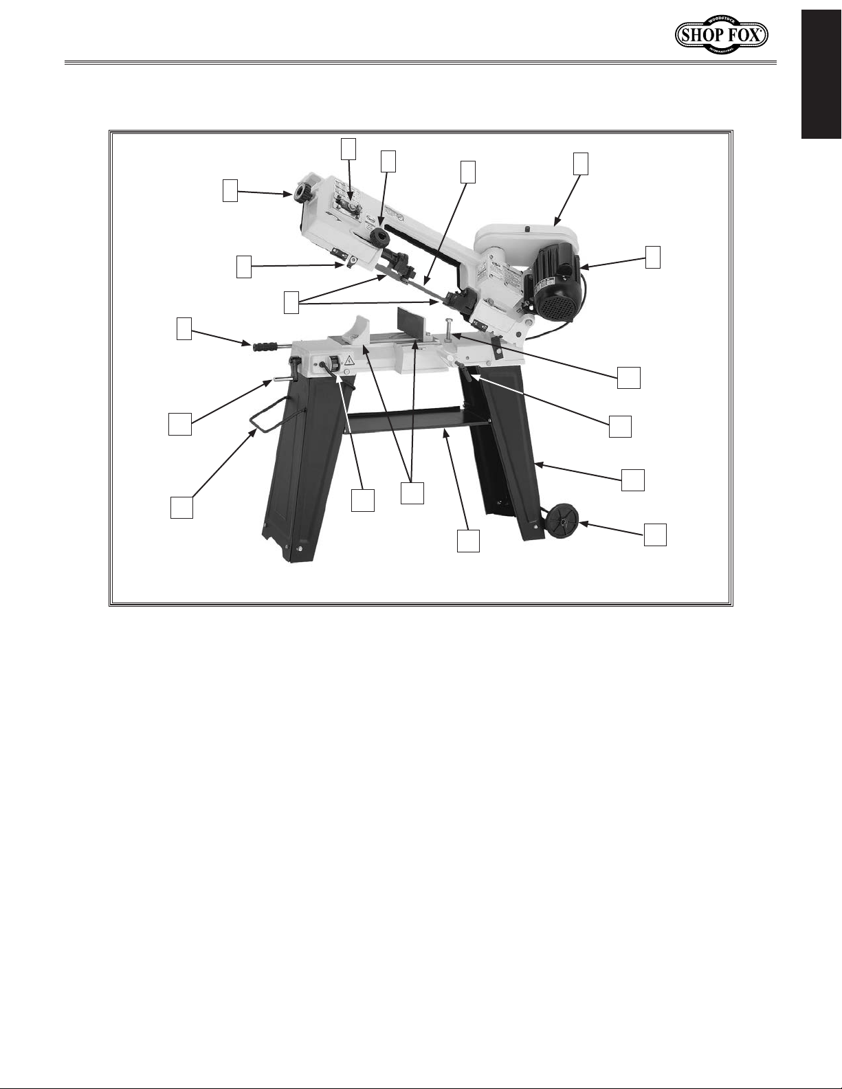
W1715 Owner's Manual (Mfg. Since 2/08)
Controls and Features
6
INTRODUCTION
5
4
3
2
10
11
7
8
9
12
Figure 1. Machine Identification.
13
14
1
18
17
16
15
1. Motor
2. Pulley Cover
3. Blade
4. Adjustable Blade Guard Knob
5. Tilting Mechanism
6. Blade Tension Knob
7. Auto Off Tab
8. Blade Guide Bearing Assemblies
9. Feed Adjustment Handle
-5-
10. Vise Crank
11. Stand Handle
12. Power Switch
13. Vise Jaws
14. Tool Tray
15. Stand Wheels
16. Stand
17. Work Stop
18. Horizontal Stop
Page 8

W1715 Owner's Manual (Mfg. Since 2/08)
SAFETY
READ MANUAL BEFORE OPERATING MACHINE.
FAILURE TO FOLLOW INSTRUCTIONS BELOW WILL
RESULT IN PERSONAL INJURY.
SAFETY
Indicates an imminently hazardous situation which, if not avoided, WILL
result in death or serious injury.
Indicates a potentially hazardous situation which, if not avoided, COULD
result in death or serious injury.
Indicates a potentially hazardous situation which, if not avoided, MAY
result in minor or moderate injury.
This symbol is used to alert the user to useful information about proper
NOTICE
operation of the equipment, and/or a situation that may cause damage
to the machinery.
Standard Safety Instructions
1. READ THROUGH THE ENTIRE MANUAL BEFORE STARTING MACHINERY. Machinery presents serious
injury hazards to untrained users.
2. ALWAYS USE ANSI APPROVED SAFETY GLASSES WHEN OPERATING MACHINERY. Everyday eye-
glasses only have impact resistant lenses—they are NOT safety glasses.
3. ALWAYS WEAR A NIOSH APPROVED RESPIRATOR WHEN OPERATING MACHINERY THAT PRODUCES
DUST. Wood dust is a carcinogen and can cause cancer and severe respiratory illnesses.
4. ALWAYS USE HEARING PROTECTION WHEN OPERATING MACHINERY. Machinery noise can cause
permanent hearing damage.
5. WEAR PROPER APPAREL. DO NOT wear loose clothing, gloves, neckties, rings, or jewelry which may
get caught in moving parts. Wear protective hair covering to contain long hair and wear non-slip
footwear.
6. NEVER OPERATE MACHINERY WHEN TIRED, OR UNDER THE INFLUENCE OF DRUGS OR ALCOHOL.
Be mentally alert at all times when running machinery.
7. ONLY ALLOW TRAINED AND PROPERLY SUPERVISED PERSONNEL TO OPERATE MACHINERY. Make
sure operation instructions are safe and clearly understood.
8. KEEP CHILDREN AND VISITORS AWAY. Keep all children and visitors a safe distance from the work
area.
9. MAKE WORKSHOP CHILD PROOF. Use padlocks, master switches, and remove start switch keys.
-6-
Page 9

W1715 Owner's Manual (Mfg. Since 2/08)
10. NEVER LEAVE WHEN MACHINE IS RUNNING. Turn power OFF and allow all moving parts to come to
a complete stop before leaving machine unattended.
11. DO NOT USE IN DANGEROUS ENVIRONMENTS. DO NOT use machinery in damp, wet locations, or
where any flammable or noxious fumes may exist.
12. KEEP WORK AREA CLEAN AND WELL LIT. Clutter and dark shadows may cause accidents.
13. USE A GROUNDED EXTENSION CORD RATED FOR THE MACHINE AMPERAGE. Undersized cords over-
heat and lose power. Replace extension cords if they become damaged. DO NOT use extension cords
for 220V machinery.
14. ALWAYS DISCONNECT FROM POWER SOURCE BEFORE SERVICING MACHINERY. Make sure switch is
in OFF position before reconnecting.
15. MAINTAIN MACHINERY WITH CARE. Keep blades sharp and clean for best and safest performance.
Follow instructions for lubricating and changing accessories.
16. MAKE SURE GUARDS ARE IN PLACE AND WORK CORRECTLY BEFORE USING MACHINERY.
17. REMOVE ADJUSTING KEYS AND WRENCHES. Make a habit of checking for keys and adjusting
wrenches before turning machinery ON.
SAFETY
18. CHECK FOR DAMAGED PARTS BEFORE USING MACHINERY. Check for binding and alignment of
parts, broken parts, part mounting, loose bolts, and any other conditions that may affect machine
operation. Repair or replace damaged parts.
19. USE RECOMMENDED ACCESSORIES. Refer to the instruction manual for recommended accessories.
The use of improper accessories may cause risk of injury.
20. DO NOT FORCE MACHINERY. Work at the speed for which the machine or accessory was designed.
21. SECURE WORKPIECE. Use clamps or a vise to hold the workpiece when practical. A secured
workpiece protects your hands and frees both hands to operate the machine.
22. DO NOT OVERREACH. Keep proper footing and balance at all times.
23. MANY MACHINES WILL EJECT THE WORKPIECE TOWARD THE OPERATOR. Know and avoid condi-
tions that cause the workpiece to "kickback."
24. ALWAYS LOCK MOBILE BASES (IF USED) BEFORE OPERATING MACHINERY.
25. BE AWARE THAT CERTAIN DUST MAY BE HAZARDOUS to the respiratory systems of people and
animals, especially fine dust. Make sure you know the hazards associated with the type of dust you
will be exposed to and always wear a respirator approved for that type of dust.
-7-
Page 10
W1715 Owner's Manual (Mfg. Since 2/08)
Additional Safety Instructions for Bandsaws
READ and understand this
entire manual before using
this machine. Serious per-
SAFETY
1. BLADE CONDITION. A dull or damaged blade can break apart during operation, increasing the risk
of operator injury. Do not operate with a dull, cracked or badly worn blade. Inspect the blade for
cracks, missing teeth, and weld condition before each use.
2. HAND PLACEMENT. Never position fingers or thumbs in line with the cut. Hands could be crushed
by machine or cut by the blade.
3. ENTANGLEMENT HAZARDS. Tie back loose clothing, jewelry, and long hair to prevent the operator
being pulled into the moving blade.
4. BLADE GUARD. The blade guard is designed to minimize operator exposure to the rotating blade
and pulleys to reduce the risk of serious injury. Always keep the blade guard in place during
operation.
sonal injury may occur
if safety and operational
information is not understood and followed. DO
NOT risk your safety by
not reading!
USE this and other machinery with caution
and respect. Always consider safety first,
as it applies to your individual working
conditions. No list of safety guidelines can
be complete—every shop environment is
different. Failure to follow guidelines could
result in serious personal injury, damage
to equipment or poor work results.
4. BLADE REPLACEMENT. The blade can only make a safe and efficient cut with the teeth facing the
workpiece in the correct direction. When replacing blades, make sure the teeth face toward the
workpiece and the pivot side of the machine. Wear gloves to protect hands and safety glasses to
protect eyes.
5. WORKPIECE HANDLING. Always support the workpiece with the table, vise, or other support
fixtures. Flag long pieces to avoid a tripping hazard. Never hold the workpiece with your hands
during a cut.
6. LOSS OF STABILITY. Unsupported workpieces may jeopardize machine stability and cause the
machine to tip or fall, which could cause serious injury or property damage.
7. POWER INTERRUPTION. Unplug the machine after a power interruption. Machines without
magnetic switches can start up after power is restored.
9. HEARING PROTECTION & HAZARDS. Noise generated by the blade and workpiece vibration,
material handling, and power transmission can cause permanent hearing loss over time and
interfere with communication and audible signals. Always wear hearing protection.
10. HOT SURFACE S. Due to friction, the workpiece, chips, and some machine components can be hot
enough to burn you.
11. STARTING POSITION. Never turn the saw ON with the blade resting on the workpiece to prevent
blade breakage that could cause a serious injury hazard to the operator.
-8-
Page 11
W1715 Owner's Manual (Mfg. Since 2/08)
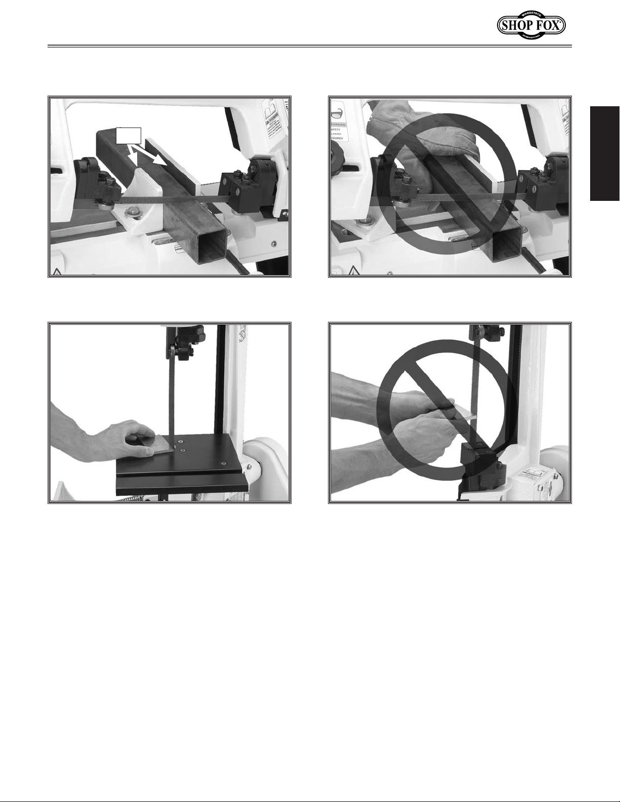
Avoiding Potential Injuries
Vise
Figure 2. Always clamp workpiece in vise when
cutting in the horizontal position.
SAFETY
Figure 4. Never cut without using the vise in the
horizontal position.
Figure 3. Always have the work table installed
when cutting in the vertical position.
Figure 5. Never cut material “free-hand” in the
vertical position.
-9-
Page 12
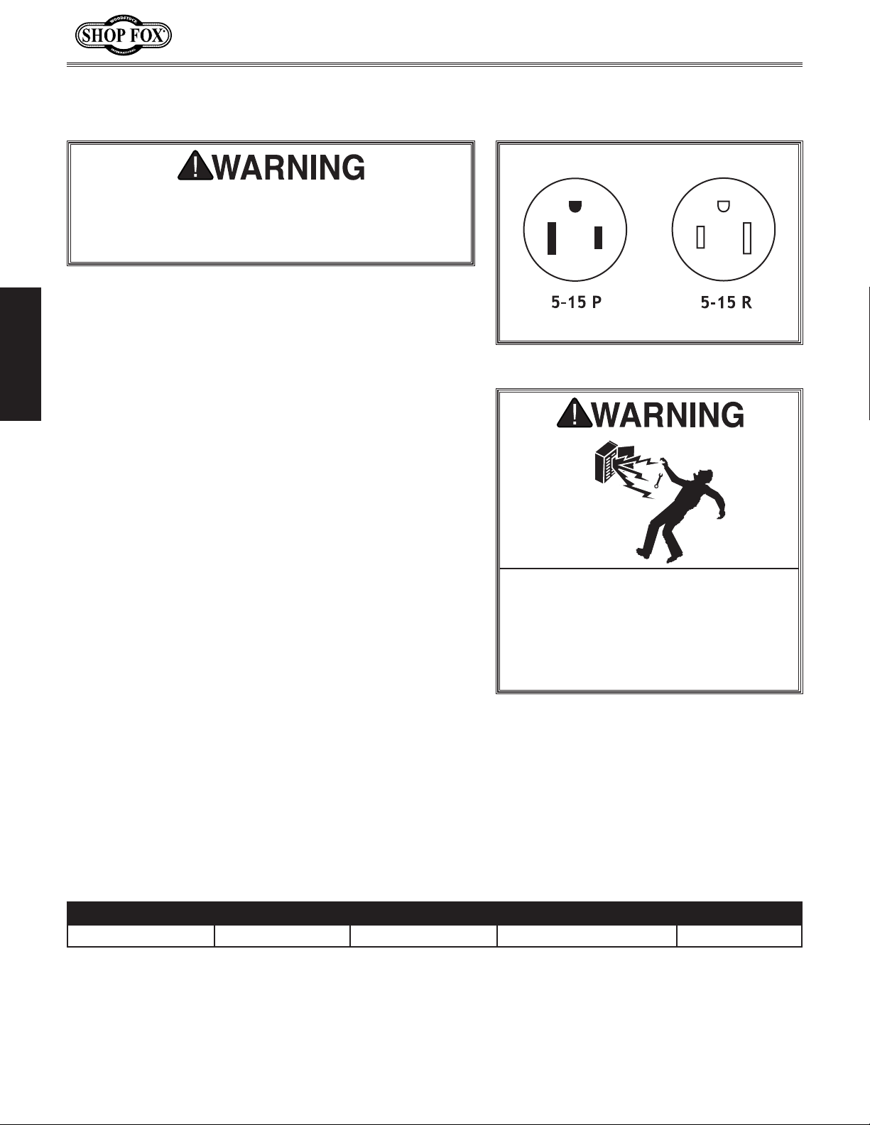
ELECTRICAL
The machine must be properly set up before it is
safe to operate. DO NOT connect this machine to the
power source until instructed to do so in the "Test
Run" portion of this manual.
110V Operation
The Model W1715 is wired for 110V operation. The power
supply circuit used for this machine MUST be grounded
and rated for the amperage given below. Never replace
a circuit breaker with one of higher amperage without
ELECTRICAL
consulting a qualified electrician to ensure compliance
with wiring codes.
W1715 Owner's Manual (Mfg. Since 2/08)
Figure 6. 5-15 plug and receptacle.
This machine must be grounded! The electrical cord
supplied with this machine comes with a grounding pin. If
your outlet does not accommodate a ground pin, have it
replaced by a qualified electrician.
If you are unsure about the wiring codes in your area
or you plan to connect your machine to a shared
circuit, you may create a fire or circuit overload
hazard—consult a qualified electrician to reduce this
risk.
Extension Cords
We do not recommend using an extension cord; however,
if you have no alternative, use the following guidelines:
• Use a cord rated for Standard Service (S).
• Do not use an extension cord longer than 50 feet.
• Ensure that the cord has a ground wire and pin.
• Use the gauge size listed below as a minimum.
DO NOT work on your electrical system
if you are unsure about electrical
codes and wiring! Seek assistance from
a qualified electrician. Ignoring this
warning can cause electrocution, fire,
or machine damage.
Electrical Specifications
Operating Voltage Amp Draw Min. Circuit Size Plug/Recommended Plug Extension Cord
110V Operation 5 Amps 15A NE M A 5 -15 14 Gauge
-10-
Page 13
W1715 Owner's Manual (Mfg. Since 2/08)
SETUP
Unpacking
This machine has been carefully packaged for safe
transportation. If you notice the machine has been
damaged during shipping, please contact your authorized
Shop Fox dealer immediately.
Inventory
The following is a description of the main components
shipped with the Model W1715. Lay the components out
to inventory them.
Note: If you can't find an item on this list, check the
mounting location on the machine or examine the
packaging materials carefully. Occasionally we pre-install
certain components for safer shipping.
Keep machine disconnected from
power until instructed otherwise.
G
B
D
SETUP
Inventory (Figure 7) Qty
A. Bandsaw (not shown) .....................................1
B. Stand Legs ..................................................2
C. Tool Tray ....................................................1
D. Corner Support Braces ....................................4
E. Wheels ......................................................2
F. Axle ..........................................................1
G. Wheel Mounting Bracket .................................1
H. Work Stop Rod .............................................1
I. Work Stop ...................................................1
J. Transport Handle ..........................................1
K. Pulley Cover ................................................1
L. V-Belt ........................................................1
M. Pulleys with Keys ..........................................2
N. Table .........................................................1
O. Table Support ..............................................1
Hardware Bag (not shown)
• Hex Wrench 4mm (Work Stop) ..........................1
• Hex Bolts M8-1.25 x 25 (Saw to Stand) ................6
• Hex Nuts M8-1.25 (Saw to Stand) .......................6
• Flat Washers 8mm (Saw to Stand) ......................6
• Hex Bolts M6-1 x 12 (Stand) .............................8
• Phillips Head Screws M6-1 x 12 (Tray) .................4
• Hex Nuts M6-1 (Stand, Tray, Table) ................... 13
• Flat Washers 6mm (Stand, Tray) ...................... 12
• Fender Washer 6mm (Table) .............................1
• Flat Head Screw M6-1 x 12 (Table) .....................1
• Cotter Pins (Axle & Handle) .............................4
F
N
O
E
K
Figure 7. The loose parts shipped with the
M
L
bandsaw.
I
H
C
J
-11-
Page 14
W1715 Owner's Manual (Mfg. Since 2/08)
Machine Placement
• Floor Load: This machine distributes a
heavy load in a small footprint. Some
residential floors may require additional
bracing to support both machine and
operator.
• Working Clearances: Consider existing and
anticipated needs, size of material to be
processed through the machine, and space
for auxiliary stands, work tables or other
machinery when establishing a location for
your Machine Type.
• Lighting: Lighting should be bright enough
to eliminate shadow and prevent eye strain.
• Electrical: Electrical circuits must be
dedicated or large enough to handle
amperage requirements. Outlets must be
located near each machine, so power or
extension cords are clear of high-traffic
SETUP
areas. Follow local electrical codes for
proper installation of new lighting, outlets,
or circuits.
Cleaning Machine
The table and other unpainted parts of your
bandsaw are coated with a waxy grease that
protects them from corrosion during shipment.
Clean this grease off with a solvent cleaner or
citrus-based degreaser. DO NOT use chlorinebased solvents such as brake parts cleaner or
acetone—if you happen to splash some onto a
painted surface, you will ruin the finish.
NEVER clean with gasoline
or other petroleumbased solvents. Most have
low flash points, which
make them extremely
flammable. A risk of
explosion and burning
exists if these products
are used. Serious personal
injury may occur if this
warning is ignored!
USE helpers or power
lifting equipment to
lift this Machine Name.
Otherwise, serious personal injury may occur.
MAKE your shop “child
safe.” Ensure that your
workplace is inaccessible
to children by closing and
locking all entrances when
you are away. NEVER allow
untrained visitors in your
shop when assembling,
adjusting or operating
equipment.
ALWAYS work in wellventilated areas far from
possible ignition sources
when using solvents to
clean machinery. Many
solvents are toxic when
inhaled or ingested. Use
care when disposing
of waste rags and
towels to be sure they
DO NOT create fire or
environmental hazards.
-12-
Page 15
W1715 Owner's Manual (Mfg. Since 2/08)
Assembly
Although the main components of the SHOP FOX® W1715
are assembled at the factory, some assembly is required.
The following series of instructions are the recommended
sequence best suited for the machine assembly.
Tools Needed Qty
Safety Glasses .....................................1 Per Person
Wrench 12mm ...................................................1
Wrench 14mm ...................................................1
Additional Person (for lifting) .................................1
Sawhorses ........................................................2
Pliers ..............................................................1
Phillips Screwdriver #2 .........................................1
Straightedge 12" Minimum .....................................1
To assemble the bandsaw, do these steps:
1. Unfold the two stand leg assemblies. They are
hinged on the edges for easy setup.
MAKE SURE that your
machine is unplugged
during all assembly
procedures! If this
warning is ignored,
serious personal injury
may occur.
Corner
Support
Brace
SETUP
2. Use the M6-1 x 12 hex bolts, M6-1 hex nuts, and
6mm flat washers to install the corner support
braces in the bottom corners of the leg assemblies
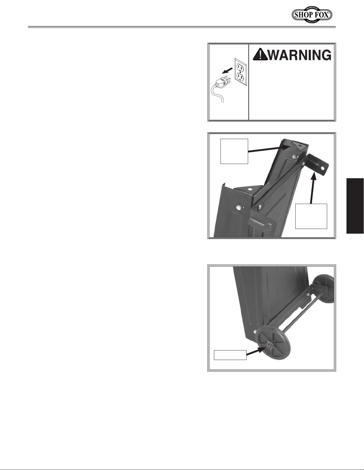
(Figure 8).
3. On one of the leg assemblies, attach the wheel
mounting bracket along with the corner support
braces to the outside bottom edge, as shown in
Figure 8.
4. Slide the axle through the holes in the wheel
mounting bracket.
5. Slide the wheels onto the axle on the outside of the
mounting brackets, and secure them with the cotter
pins, as shown in Figure 9.
Wheel
Mounting
Bracket
Figure 8. Corner support brace and wheel
mounting bracket.
Cotter Pin
Figure 9. Wheel installed with cotter pin.
-13-
Page 16

6. On the other leg, insert the handle into the pre-
drilled holes and secure it with the cotter pins (see
Figure 10).
The bandsaw is a heavy
machine (144 lbs.) Use
assistance and safe lifting/
moving methods when lifting
this machine.
7. With the help of an assistant, lift the bandsaw onto
a pair of closely spaced sawhorses or other suitable
support (see Figure 11).
8. Attach the legs to the bandsaw with the M8-1.25 x
25 hex bolts, 8mm flat washers, and M8-1.25 hex
nuts. Tighten them with a 14mm wrench or socket
just enough to secure the parts. Final tightening will
take place when the stand is fully assembled.
W1715 Owner's Manual (Mfg. Since 2/08)
Cotter
Pin
Figure 10. Handle installed with cotter
pins.
9. Remove the machine from the sawhorses, then
SETUP
install the tool tray in the middle of the stand with
the M6-1 x 12 Phillips head screws, 6mm flat washers
and M6-1 hex nuts, as shown in Figure 12.
10. Check to see if the bandsaw is relatively level, then
final tighten all the nuts.
Figure 11. Attaching leg assemblies.
-14-
Figure 12. Installing tool tray.
Page 17

W1715 Owner's Manual (Mfg. Since 2/08)
11. Place the pulley cover over the motor and gear
shafts, and secure it with the pre-installed M6-1 x
12 Phillips head screws and 12mm flat washers, as
shown in Figure 13.
12. Open the pulley cover, then insert the keys into the
slots on the pulley shafts.
13. Slide the large diameter motor pulley onto the motor
shaft (see Figure 14).
14. Install the worm gear pulley with the small diameter
wheel on the shaft closest to the gear box.
15. Use a straightedge to check the alignment of the
pulley wheels, as shown in Figure 15, and adjust
them as needed.
16. When the pulley wheels are aligned, tighten the set
screws on both pulleys.
Figure 13. Installing the pulley cover.
Motor Pulley
w/Key Slot
SETUP
Figure 14. Motor pulley installed.
-15-
Figure 15. Checking the pulley alignment.
Page 18

17. Unthread the V-belt tension hex bolt, then pivot
the motor up and slide the V-belt into the pulley
grooves, as shown in Figure 16.
18. Release the motor, letting its weight tension the
V-belt, then thread the V-belt tension hex bolt
against the side of the bandsaw.
19. Install the work stop shaft into the side of the
bandsaw then lock it in place by tightening the set
screw, as shown in Figure 17.
20. Slide the work stop onto the end of the shaft and
lock it into position with the locking lever, as shown
in Figure 18.
W1715 Owner's Manual (Mfg. Since 2/08)
V-belt Tension
Hex Bolt
Figure 16. Installing the V-belt.
SETUP
Figure 17. Installing the work stop shaft.
Locking
Lever
-16-
Figure 18. Work stop locking lever
installed.
Page 19

W1715 Owner's Manual (Mfg. Since 2/08)
Test Run
Once the assembly is complete, test run the machine to
make sure it runs properly for regular operations.
The test run consists of verifying the following: 1) The
motor powers up and runs correctly, and 2) the safety
disabling mechanism on the switch works correctly.
If, during the test run, you cannot easily locate the source
of an unusual noise or vibration, stop using the machine
immediately, then review Troubleshooting on Page 37.
If you still cannot remedy a problem, contact our Tech
Support at (360) 734-3482 for assistance.
To test run the machine, do these steps:
1. Read the entire instruction manual.
2. Make sure all tools and foreign objects have been
removed from the machine.
3. Connect the bandsaw to power.
4. Put on safety glasses and secure loose clothing or
long hair.
5. Raise the bandsaw by the handle.
6. Start the bandsaw while keeping your finger near
the ON/OFF switch at all times during the test run
(Figure 19). The bandsaw should run smoothly with
little or no vibration.
Projectiles thrown from the machine
could cause serious eye injury. Wear
safety glasses to reduce the risk of
injury.
SETUP
Figure 19. ON/OFF switch.
— If you suspect any problems, immediately stop the
bandsaw and correct before continuing.
-17-
Page 20

OPERATIONS
General
This machine will perform many types of operations
that are beyond the scope of this manual. Many of these
operations can be dangerous or deadly if performed
incorrectly.
The instructions in this section are written with the
understanding that the operator has the necessary
knowledge and skills to operate this machine. If at any
time you are experiencing difficulties performing any
operation, stop using the machine!
If you are an inexperienced operator, we strongly
recommend that you read books or trade articles, or
seek training from an experienced metal cutting bandsaw
operator before performing any unfamiliar operations.
Above all, your safety should come first!
W1715 Owner's Manual (Mfg. Since 2/08)
READ and understand this entire instruction manual before using this machine.
Serious personal injury may occur if
safety and operational information is not
understood and followed. DO NOT risk
your safety by not reading!
OPERATIONS
DO NOT investigate problems or adjust
the machine while it is running. Wait
until the machine is turned OFF,
unplugged and all working parts
have come to a complete stop before
proceeding!
Always wear safety glasses when operating this machine. Failure to comply
may result in serious personal injury.
-18-
Page 21

W1715 Owner's Manual (Mfg. Since 2/08)
Operation Tips
The following tips will help you safely and effectively
operate your bandsaw and help you get the maximum life
out of your saw blades.
Horizontal Cutting
• Use the work stop to quickly and accurately cut
multiple pieces of stock to the same length (see
Figure 20).
• Clamp the material firmly in the vise jaws to ensure
a straight cut through the material.
• Allow the blade reach full speed before engaging
the workpiece. Never start a cut with the blade in
contact with the workpiece (see Figure 21).
• Chips should be curled and silvery. If the chips are
thin and powder like, increase your feed rate (refer
to the Metal Chip Inspection Chart on Page 27).
Figure 20. Work stop and lever.
• If the chips are burned, reduce the blade speed.
• Wait until the blade has completely stopped before
removing the workpiece from the vise, and avoid
touching the cut end—it could be very hot!
Vertical Cutting
• Workpieces that cannot be properly supported or
stabilized without a vise should not be cut in the
vertical position. Examples are chains, cables, round
or oblong-shaped workpieces, workpieces with
internal or built-in moving or rotating parts, etc.
• Make sure that the vertical table assembly is
securely fastened to the bandsaw frame so it will
adequately support the workpiece.
• Always keep your fingers away from the blade and
always hold the workpiece securely in your hand
(Figure 22).
• Adjust the blade guides as close as possible to the
workpiece to minimize side-to-side blade movement.
OPERATIONS
Figure 21. Proper bandsaw horizontal
starting position.
NOTICE
Release the blade tension at the end of the day to
prolong blade life.
-19-
Figure 22. Proper bandsaw vertical
starting position.
Page 22

Vertical Operation
The Model W1715 can easily be set up for vertical cutting
operations to make cuts that are not a straight cut
through the entire workpiece, such as curves or pattern
cuts.
To assemble the bandsaw for vertical cutting, do these
steps:
1. DISCONNECT BANDSAW FROM POWER!
2. Remove the two flat head screws and the blade
guide cover shown in Figure 23.
3. Install the table and replace the two screws removed
in Step 2.
4. Install the table bracket with the pre-installed hex
bolt, the M6-1 x 12 flat head screw, and the M6-1
hex nut, as shown in Figure 24.
W1715 Owner's Manual (Mfg. Since 2/08)
Blade
Guide
Cover
Figure 23. Blade guide cover.
5. Place a level on the table, as shown in Figure 25,
then use the adjustment bolt shown in Figure 26 to
make the table level.
OPERATIONS
Bolt Already
In Casting
Figure 24. Table and table bracket
installed.
Figure 25. Adjusting table with a level.
-20-
Adjustment
Bolt
Figure 26. Table adjustment bolt.
Page 23

W1715 Owner's Manual (Mfg. Since 2/08)
6. Install the safety bracket and lock it in place with
the pin shown in Figure 27 to keep the saw from
falling.
Note: To ensure the safety bracket fits securely in
the notch on the body frame, the safety bracket
may need to be slightly "modified" with a hammer
or other appropriate implement to fit securely.
Head Locking Pin
Notch
Safety
Bracket
Pin
The head locking pin secures the head in the down,
horizontal position. You MUST secure the head with
the locking pin before moving the machine to prevent the head unexpectedly springing up, causing the
machine to tip or fall. Otherwise, serious personal
injury or property damage could occur.
The head locking pin safely secures the head in the down
position. To ensure the head does not unexpectedly
spring up and tip the bandsaw over, this locking pin must
be properly inserted when the bandsaw is not in use or
before moving it.
To use the head locking pin, do these steps:
1. DISCONNECT BANDSAW FROM POWER!
2. Fully lower the head down, then insert the locking
pin through the holes in the head pivot arm and
base, as shown in Figure 28.
Figure 27. Safety bracket in position.
Head Locking Pin
OPERATIONS
Figure 28. Head locking pin correctly
installed.
3. Before connecting the machine to power, remove the
locking pin.
-21-
Page 24

Using the Vise
The vise is designed to secure the workpiece during
horizontal cutting operations. Always use the vise when
cutting with the bandsaw in the horizontal position.
Tools Needed Qty
Machinist's Square ..............................................1
W1715 Owner's Manual (Mfg. Since 2/08)
To use the vise on your bandsaw, do these steps:
1. DISCONNECT BANDSAW FROM POWER!
2. Check the vise with a machinist's square to make sure
the vise is perpendicular to the blade and reads 0˚ on
the scale as shown in Figure 29.
3. When the vise is square to the blade, place the
material to be cut between the vise jaws.
4. Turn the vise crank handle (Figure 30) clockwise to
firmly secure the workpiece in the vise jaws. The
workpiece is now ready to cut.
Clamping Angles
The vise can hold workpieces for angle cuts ranging from
0˚ to 60˚.
Tools Needed Qty
Wrench or Socket 14mm .......................................1
OPERATIONS
Scale
Figure 29. Using a machinist's square to
adjust the vise perpendicular to the blade.
Vise Crank
Handle
To adjust the vise for angle cuts, do these steps:
1. DISCONNECT BANDSAW FROM POWER!
2. Loosen the hex bolts on the stationary vise jaw, as
shown in Figure 31.
3. Rotate the sliding edge of the vise to the desired
angle, indicated by the scale, and secure the bolts.
4. Place the workpiece between the jaws and clamp
firmly.
Note: The vise jaw on the lead screw pivots freely to
match the angle of the other jaw.
-22-
Figure 30. Vise crank handle.
Hex Bolts
Figure 31. Loosening vise hex bolts.
Page 25

W1715 Owner's Manual (Mfg. Since 2/08)
Blade Guides
The blade guides should be as close to the workpiece as
possible. This will help ensure straight cuts by keeping the
blade from twisting and drifting off the cut line.
Adjustment Knob
To adjust the blade guides, do these steps:
1. DISCONNECT BANDSAW FROM POWER!
2. Loosen the adjustment knob shown in Figure 32 and
slide the blade guide as close to the workpiece as
possible, then re-tighten the knob.
Feed Rate
The feed rate is controlled by the spring and handle
shown in Figure 33.
For Slower Feed Rate: Twist the handle clockwise to add
tension to the spring.
For Faster Feed Rate: Twist the handle counterclockwise
to remove tension from the spring.
Blade Guides
Figure 32. Blade guide adjustment knob.
Spring
OPERATIONS
Handle
Figure 33. Feed rate spring and handle.
-23-
Page 26

Blade Speed
Motor PulleyGear Pulley
C
B
A
The bandsaw is capable of operating at 78, 108, or 180
FPM. The speed can easily be adjusted by changing the
V-belt placement. Figure 34 shows an illustration of each
pulley to belt combination, and the following list provides
the blade speeds in feet per minute.
Belt Position Blade Speed
A ....................................................... 78 FPM
B ......................................................108 FPM
C ......................................................180 FPM
To change the blade speeds, do these steps:
1. DISCONNECT BANDSAW FROM POWER!
2. Unthread the V-belt tension hex bolt to allow the
motor to pivot (Figure 35).
W1715 Owner's Manual (Mfg. Since 2/08)
Figure 34. Pulley configurations.
V-belt Tension
Hex Bolt
3. Raise the motor to relieve the belt tension and
position the belt in the desired pulley alignment.
4. Release the motor and let the motor weight tension
the belt.
5. Position the V-belt tension hex bolt back against the
frame of the bandsaw.
OPERATIONS
Figure 35. V-belt tension hex bolt.
-24-
Page 27

W1715 Owner's Manual (Mfg. Since 2/08)
Blade Terminology
Selecting the right blade for the cut requires a knowledge
of various blade characteristics. Use the illustration
in Figure 36 and the following descriptions to better
understand blade characteristics.
A
A. Kerf: The width of the cut by the blade during
cutting.
B. Tooth Set: The amount each tooth is bent left or
right from the blade.
C. Gauge: The thickness of the blade.
D. Blade Width: The widest point of the blade
measured from the tip of the tooth to the back edge
of the blade.
E. Tooth Rake: The angle of the tooth from a line
perpendicular to the length of the blade.
F. Gullet Depth: The distance from the tooth tip to the
bottom of the curved area (gullet).
G. Tooth Pitch: The distance between tooth tips.
H. Blade Back: The distance between the bottom of the
gullet and the back edge of the blade.
B
C
D
Figure 36. Bandsaw blade components.
E
F
H
G
I
OPERATIONS
I. TPI: The number of teeth per inch measured from
gullet to gullet.
-25-
Page 28

Blade Selection
W1715 Owner's Manual (Mfg. Since 2/08)
Blade Size
The Model W1715 accepts only 1⁄2" x 0.025 x 64 1⁄2" blades.
Tooth Pitch
Usually measured as TPI (Teeth Per Inch), tooth pitch
determines the size/number of the teeth. More teeth
per inch (fine pitch) will cut slower, but smoother; while
fewer teeth per inch (coarse pitch) will cut rougher, but
faster.
As a general rule, choose blades that will have at least
three teeth in the material at all times. Use fine pitched
blades on harder metals and coarse pitched blades on
softer metals. When selecting blades, refer to Figure 37
for recommended blade tooth (TPI) and speed (FPM)
based on the workpiece material.
Tooth Style
When selecting blades, another option to consider is the
shape, gullet size, teeth set and teeth angle—otherwise
known as “Tooth Style." Many blade manufacturers offer
variations of the four basic styles shown in Figure 38.
Material TPI FPM
Tool Steel
Stainless Steel
Bearing Bronze
Mild Steel
Hard Brass
Bronze
Soft Brass
Aluminum
Other Light Metals
Figure 37. Blade TPI and FPM chart.
Standard (or Raker)
Skip (or Skip Tooth)
Hook (or Claw)
24 78
18 108
14 180
Tooth Set
Three of the most common tooth sets are alternate, wavy,
and raker (see Figure 39).
OPERATIONS
Variable Pitch (VP)
Figure 38. Bandsaw blade tooth styles.
Alternate Wavy Raker
Figure 39. Bandsaw blade tooth sets.
-26-
Page 29

W1715 Owner's Manual (Mfg. Since 2/08)
thin & curled
thin & curled
short, hard & thick
thin & curled
short, hard & thick
thick, hard & strong
thin & curled
short, hard & thick
thick, hard & strong
thick, hard & strong
thin & curled
short, hard & thick
thick, hard & strong
thick, hard & strong
hard & thin
thin & curled
short, hard & thick
thick, hard & strong
thick, hard & strong
thin & straight
hard & thin
thin & curled
short, hard & thick
thick, hard & strong
thick, hard & strong
thin & straight
powdery
hard & thin
thin & curled
short, hard & thick
thick, hard & strong
thick, hard & strong
thin & straight
powdery
thin & curled tightly
hard & thin
Metal Chip Inspection Chart
The best method of evaluating the performance of your metal cutting operation is to inspect the chips
that are formed from cutting. Refer to the chart below for chip inspection guidelines.
Chip
Appearance
Chip
Description
Thin & Curled Silver
Hard, Thick &
Short
Hard, Strong &
Thick
Hard, Strong &
Thick
Chip
Color
Blade
Speed
Feed
Pressure
Good Good
Brown or Blue Decrease Decrease
Brown or Blue Decrease Decrease
Silver or Light
Brown
Good
Decrease
Slightly
Hard & Thin Silver Increase Decrease
Straight & Thin Silver
Good
Increase
Additional
Actions
Lubricate with
a small amount
of oil
Lubricate with
a small amount
of oil
Check Blade
Pitch
Check Blade
Pitch
OPERATIONS
Powdery Silver Decrease Increase
Curled Tight &
Thin
Silver
Good
Figure 40. Metal chip inspection chart.
Decrease
Check Blade
Pitch
-27-
Page 30

W1715 Owner's Manual (Mfg. Since 2/08)
ACCESSORIES
Metal Cutting Bandsaw Accessories
The following Metal Cutting Bandsaw accessories may be available through your local Woodstock
International Inc. Dealer. If you do not have a dealer in your area, these products are also available
through online dealers. Please call or e-mail Woodstock International Inc. Customer Service to get a
current listing of dealers at: 1-800-840-8420 or at sales@woodstockint.com.
Metal Cutting Bandsaw Blades
D3320—64-1/2" x 1/2" x 0.025" 10 TPI
D3321—64-1/2" x 1/2" x 0.025" 14 TPI
D3322—64-1/2" x 1/2" x 0.025" 18 TPI
D3323—64-1/2" x 1/2" x 0.025" 24 TPI
Model D2273 Single Roller Stand
Large diameter ball bearing roller stand features smooth operation
for a variety of processing and work support applications. Heavy
pedestal base is stable and secure.
Model D2274 5 Roller Stand
For greater work stability and support, this 5 roller stand features
large diameter, ball bearing rollers mounted on a sturdy adjustable
pedestal base.
Shop Fox Safety Glasses
Exceeding ANSI Z87.1-1989 standards for impact resistance, these
OPERATIONS
Safety Glasses offer outstanding eye protection and stylish good
looks. Wrap-around side shields provide additional protection and a
wide field of view. Model D2676 features easily adjustable ear pieces
for length and comfort.
D2273 D2274
D2675
D2676
-28-
Page 31

W1715 Owner's Manual (Mfg. Since 2/08)
MAINTENANCE
General
Regular periodic maintenance on your machine will
ensure its optimum performance. Make a habit of
inspecting your machine each time you use it.
Check for the following conditions and repair or
replace when necessary:
• Loose mounting bolts.
• Worn switch.
• Worn or damaged cords and plugs.
• Damaged bandsaw blade.
• Any other condition that could hamper the safe
operation of this machine.
MAKE SURE that your machine is
unplugged during all maintenance procedures! If this warning is ignored, serious personal injury may occur.
Cleaning
Frequently use a brush and a shop vacuum to remove
chips and other debris from the machine. Keep the nonpainted surfaces rust-free with regular applications of an
anti-rust protectorate.
Periodically, remove the blade and thoroughly clean all
metal chips or built-up grease from the wheel surfaces
and blade housing.
Lubrication
Before applying lubricant to any area, wipe the area clean
to avoid contamination. Lubricate the vice screw shown in
Figure 41 with multi-purpose gear grease.
Remove the cover on the gearbox shown in Figure 42 and
coat the gears with multi-purpose gear grease.
Vise
Screw
Figure 41. Vise screw.
MAINTENANCE
Gearbox
Cover
-29-
Figure 42. Gearbox cover.
Page 32

SERVICE
Blade Change
Blades should be changed when they become dull,
damaged, or when your operation requires a different
blade.
To change the blade on the bandsaw, do these steps:
W1715 Owner's Manual (Mfg. Since 2/08)
1. DISCONNECT BANDSAW FROM POWER!
2. Raise the head of the bandsaw to the vertical
position, use the head locking pin to hold it in place,
then remove the wheel access cover.
3. Loosen the tension knob and slip the blade off of the
wheels.
4. Install the new blade through both blade guide
bearings, as shown in Figure 43, and around the
bottom wheel.
5. Hold the blade around the bottom wheel with one
hand and slip it around the top wheel with the other
hand, keeping the blade between the blade guide
bearings.
Note: It is sometimes possible to flip the blade
inside out, in which case the blade will be installed
in the wrong direction. Check to make sure the
blade teeth are facing toward the workpiece, as
shown in Figure 44, after mounting to the bandsaw.
Some blades will have a directional arrow as a
guide.
Blade
Guide
Bearings
Figure 43. Installing the blade.
Blade Travel
Figure 44. Correct blade travel.
6. When the blade is around both wheels, adjust the
position so the back of the blade is against the
shoulder of the wheels (see Figure 45).
7. Tighten the tension knob so the blade will not slip on
the wheels upon start up.
8. Connect the bandsaw to the power source.
SERVICE
9. Briefly turn the bandsaw ON then OFF to position
the blade and resume the previous tracking.
—If the tracking needs to be adjusted, see Blade
Tracking in the next section.
—If the tracking is fine, proceed to Blade Tension on
Page 32.
Shoulder
Figure 45. Blade installed on the top
wheel.
-30-
Page 33

W1715 Owner's Manual (Mfg. Since 2/08)
Blade Tracking
The blade tracking has been properly set at the factory.
The tracking will rarely need to be adjusted if the
bandsaw is used properly.
Tools Needed Qty
Wrench or Socket 14mm .......................................1
To adjust the blade tracking on the bandsaw, do these
steps:
1. DISCONNECT BANDSAW FROM POWER!
2. Position the bandsaw in the vertical position.
3. Open the wheel access cover.
4. Loosen, but do not remove the lower hex bolt in the
blade wheel tilting mechanism shown in Figure 46.
5. Use the blade tension knob to release the blade
tension (see Figure 47).
6. Adjust the tracking hex bolt, as shown in Figure 47,
then tighten the lower hex bolt loosened in Step 4.
—Tightening the tracking hex bolt will move the
blade closer to the shoulder of the wheel.
—Loosening the tracking hex bolt will move the
blade away from the shoulder.
Lower
Hex Bolt
Figure 46. Blade wheel tilting lower hex
bolt.
Blade
Tracking
Hex Bolt
Tension
Knob
7. Tension the blade.
8. Reconnect the power and turn ON the bandsaw.
—If the blade tracks along the shoulder of the wheel
(without rubbing), the blade is tracking properly
and this adjustment is completed.
—If the blade walks away from the shoulder of the
wheel or hits the shoulder, turn the bandsaw OFF,
disconnect it from power, then repeat Steps 4-8.
9. Turn the bandsaw OFF, disconnect it from power,
then replace the blade guard and wheel access
cover.
-31-
Figure 47. Adjusting the tracking hex bolt.
SERVICE
Page 34

Blade Tension
Proper blade tension is essential to long blade life,
straight cuts, and efficient cutting times.
Two major signs that you do not have the correct blade
tension are: 1) The blade stalls in the cut and is slipping
on the wheels, and 2) the blade frequently breaks from
being too loose.
To tension the blade on the bandsaw, do these steps:
1. Make sure the blade is tracking properly.
W1715 Owner's Manual (Mfg. Since 2/08)
2. DISCONNECT BANDSAW FROM POWER!
3. Loosen and slide the blade guides as far apart as
they will go then tighten them down again.
4. Turn the blade tension knob in Figure 48 clockwise
to tighten the blade as tight as you can.
5. Using moderate finger pressure, push against the
side of the blade. The blade should not move more
than 0.004".
Squaring Blade
It is always a good idea during the life of your saw
to check and adjust this setting. This adjustment will
improve your cutting results and extend the life of your
blade.
To square the blade to the bed of the table, do these
steps:
Blade
Tension Knob
Figure 48. Blade tension knob.
Hex Bolt
1. DISCONNECT BANDSAW FROM POWER!
2. Separate the blade guides as far as possible, the
lower the head of the bandsaw all the way until it
contacts the horizontal stop.
3. Place a square on the table bed and against the edge
of the blade (Figure 49), and check different points
SERVICE
along the length of the table between the blade
guides.
4. Loosen the hex bolt shown in Figure 49, and rotate
the seat until the blade is vertical to the bed, then
re-tighten the hex bolt.
Figure 49. Squaring the blade.
-32-
Page 35

W1715 Owner's Manual (Mfg. Since 2/08)
Blade Guide Bearings
The blade guide bearings must be properly adjusted to
make square cuts. One bearing on each assembly has an
eccentric bushing that allows it to be adjusted so the
blade is square to the vise. The bearings are secured
in place by a hex nut and lock washer, as shown in
Figure 50.
Before adjusting the blade guide bearings, make sure that
you have squared the blade to the table as discussed in
the previous section.
To adjust the blade guide bearings, do these steps:
Backing Bearing
Hex
Nut
1. DISCONNECT BANDSAW FROM POWER!
2. Position the vise to 90°, then lock it in place.
3. Put a machinist's square against the face of the vise
and move it over to the blade.
— The square should evenly touch both the face of
the vise and the blade. If it does, skip ahead to
Step 6.
— If the square does not evenly touch the blade, but
it does evenly touch the vise, continue with the
next step.
4. Loosen the hex nuts that secure the eccentric
bushings attached to the guide bearings.
5. Adjust the bearings as necessary to force the blade
to be 90° to the vise, then re-tighten the hex nuts.
6. If any of the bearings are not touching the blade
evenly, loosen the hex nuts and adjust them so the
contact surface of the bearings touch the blade
evenly.
Eccentric Bushing
Figure 50. Blade guide adjustment
controls.
Note: Since the bearings twist the blade into
position, it is acceptable if there is 0.001"-0.002"
gap between the blade and the front or back of
the bearing. Just make sure not to squeeze the
blade too tightly with the bearings. After the guide
bearings are set, you should be able to rotate the
guide bearings (although they will be stiff) with
your fingers.
7. Adjust the backing bearing in the same manner, but
leave a gap between 0.002-0.003" from the back of
the blade.
-33-
SERVICE
Page 36

Changing V-Belt
Check the V-belt periodically for signs of glazing, cracking,
or fraying. If any of these conditions are present, change
the V-belt.
To change the V-belt, do these steps:
1. DISCONNECT BANDSAW FROM POWER!
2. Loosen the V-belt tension hex bolt on the motor
mounting plate to allow the motor to pivot (see
Figure 51).
3. Open the pulley cover door to access the V-belt, as
shown in Figure 52.
4. Pivot the motor towards the gear box to release belt
tension and remove the V-belt.
W1715 Owner's Manual (Mfg. Since 2/08)
V-Belt Tension
Hex Bolt
Figure 51. V-belt tension hex bolt.
5. Replace the V-belt and let the weight of the motor
provide the tension.
6. Secure the V-belt tension bolt.
Figure 52. Installing the V-belt.
SERVICE
-34-
Page 37

W1715 Owner's Manual (Mfg. Since 2/08)
SHOCK HAZARD.
QUALIFIED ELECTRICIAN
WIRE CONNECTIONS.
WIRE/COMPONENT DAMAGE
. The motor wiring shown in these
shocked, wait at least this long before working
Electrical Safety Instructions
These pages are current at the time of printing. However, in the spirit of improvement, we may
make changes to the electrical systems of future machines. Study this diagram carefully. If you notice
differences between your machine and these wiring diagrams, call Woodstock International Technical
Support at (360) 734-3482.
connected to a power source is extremely
dangerous. Touching electrified parts will
result in personal injury including but not
limited to severe burns, electrocution,
or death. Disconnect the power from
the machine before servicing electrical
components!
hazards of electricity, only a qualified
electrician should perform wiring tasks on this
machine. If you are not a qualified electrician,
get help from one before attempting any kind
of wiring job.
tight to prevent wires from loosening during
machine operation. Double-check all wires
disconnected or connected during any wiring
task to ensure tight connections.
or components increase the risk of serious
personal injury, fire, or machine damage.
If you notice that any wires or components
are damaged while performing a wiring task,
replace those wires or components before
completing the task.
Working on wiring that is
. Due to the inherent
All connections must be
. Damaged wires
MOTOR WIRING
diagrams is current at the time of printing,
but it may not match your machine. Always
use the wiring diagram inside the motor
junction box.
MODIFICATIONS. Using aftermarket parts or
modifying the wiring beyond what is shown
in the diagram may lead to unpredictable
results, including serious injury or fire.
CAPACITORS/INVERTERS. Some capacitors and
power inverters store an electrical charge for
up to five minutes after being disconnected
from the power source. To avoid being
on these components.
ELECTRICAL REQUIREMENTS. You MUST follow
the electrical requirements at the beginning
of this manual when connecting your machine
to a power source.
EXPERIENCING DIFFICULTIES. If you are
experiencing difficulties understanding the
information included in this section, contact
our Technical Support at (360) 734-3482.
The photos and diagrams
included in this section are
best viewed in color. You
can view these pages in
color at www.shopfox.biz.
BLACK
WHITE
GREEN
RED
WIRING DIAGRAM COLOR KEY
BLUE
BROWN
GRAY
ORANGE
-35-
YELLOW
YELLOW
GREEN
PURPLE
PINK
LIGHT
BLUE
BLUE
WHITE
TURQUOISE
SERVICE
Page 38

Power Cord
W1715 Owner's Manual (Mfg. Since 2/08)
Electrical Components
Figure 53. ON/OFF switch wiring.
Wiring Diagram
Read
Page 35
STOP
Before
Wiring
110V
Motor
Capacitor
35MFD 250VAC
Switch
Figure 54. Start capacitor.
Ground
Ground
WARNING
ACCIDENTAL INJURY
SERVICE
HAZARD!
Disconnect power
supply before
adjustments, setup,
or maintenance!
-36-
Neutral
Hot
110V NEMA 5-15
(As Recommended)
Page 39

W1715 Owner's Manual (Mfg. Since 2/08)
Troubleshooting
This section covers the most common problems and corrections with this type of
machine. WARNING! DO NOT make any adjustments until power is disconnected and
moving parts have come to a complete stop!
PROBLEM POSSIBLE CAUSE CORRECTIVE ACTION
Machine does not start or a
breaker trips.
1. Plug/receptacle is at fault or wired
incorrectly.
2. Start capacitor is at fault.
3. Motor connection wired incorrectl y.
4. Power supply is at fault/switched
OFF.
1. Test for good contact or correct the wiring.
2. Test/replace if faulty.
3. Correct motor wiring connections.
4. Make sure all hot lines/grounds are operational and
have correct voltage on all legs.
Machine stalls or is underpowered.
Machine has vibration or
noisy operation.
Machine is loud when cutting or bogs down in the
cut.
5. ON/OFF switch is at fault.
6. Wiring is open/has high resistance.
7. Motor is at fault.
1. Wrong blade for the workpiece
material (metal).
2. Feed rate too fast for task.
3. V-belt slipping.
4. Blade is slipping on wheels.
5. Pulley/sprocket slipping on shaft.
6. Motor bearings are at fault.
7. Motor is at fault.
1. V-belt is slapping belt cover.
2. V-belt worn or loose.
3. Pulley is loose.
1. Excessive feed rate.
2. The blade TPI is too great, or the
material is too coarse.
5. Replace faulty ON button or ON/OFF switch.
6. Troubleshoot wires for internal/external breaks;
check for disconnected/corroded connections;
repair/replace wiring.
7. Test/repair/replace.
1. Use blade with correct properties for your type of
cutting.
2. Decrease feed rate.
3. Replace bad V-belt and re-tension.
4. Adjust blade tracking and tension.
5. Replace loose pulley/shaft.
6. Test by rotating shaft; rotational grinding/loose
shaft requires bearing replacement.
7. Test/repair/replace.
1. Inspect belt cover for proper installation.
2. Inspect/replace belt with a new one.
3. Realign/replace shaft, pulley, setscrew, and key as
required.
1. Refer to Feed Rate on Page 23, or Blade Speed on
Page 24 and adjust as required.
2. Refer to Blade Selection on Page 26 and adjust as
required.
-37-
SERVICE
Page 40

PROBLEM POSSIBLE CAUSE CORRECTIVE ACTION
Blades break often. 1. The workpiece is loose in the vise.
2. The feed or cut speed is wrong.
3. The blade TPI is too great, or the
material is too coarse.
4. The blade is rubbing on the wheel
flange.
5. The bandsaw is being started with
the blade resting on the workpiece.
6. The guide bearings are misaligned,
or the blade is rubbing on the
wheel flange.
7. The blade is too thick, or the
blades are of low quality.
Blade dulls prematurely. 1. The cutting speed is too fast.
2. The blade TPI is too coarse.
3. The blade feed pressure is too
light.
4. The workpiece has hard spots,
welds, or scale is on the material.
5. The blade is twisted.
6. The blade is slipping on the
wheels.
Blade wears on one side. 1. The blade guides are worn or mis-
adjusted.
2. The blade guide slide bracket is
loose.
3. The wheels are out of alignment.
Teeth are ripping from the
blade.
The cuts are crooked. 1. The feed pressure is too high.
SERVICE
1. The feed pressure is too heavy and
the blade speed is too slow; or
the blade TPI is too coarse for the
workpiece.
2. The workpiece is vibrating in the
vise.
3. The blade gullets are loading up
with chips.
2. The guide bearings are out of
adjustment, or too far away from
the workpiece.
3. The blade tension is low.
4. The blade is dull.
5. The blade speed is wrong.
W1715 Owner's Manual (Mfg. Since 2/08)
1. Clamp the workpiece tighter, or use a jig to hold the
workpiece.
2. Refer to Feed Rate on Page 23, or Blade Speed on
Page 24 and adjust as required.
3. Refer to Blade Selection on Page 26 and adjust as
required.
4. Refer to Blade Tracking on Page 31, and adjust as
required.
5. Start bandsaw and then slowly lower the headstock
by setting the feed rate.
6. Refer to Blade Tracking on Page 31, or Blade Guides
on Page 23, and adjust as required.
7. Use a higher quality blade.
1. Refer to Blade Speed on Page 24 and adjust as
required.
2. Refer to Blade Selection on Page 26 and adjust as
required.
3. Refer to Feed Rate on Page 23, and adjust as
required.
4. Increase the feed pressure, and reduce the cutting
speed.
5. Replace the blade.
6. Refer to Blade Tension on Page 32, and adjust as
required.
1. Refer to Blade Guides on Page 23 and replace or
adjust.
2. Tighten the blade guide bracket.
3. Refer to Blade Tracking on Page 31, and adjust as
required.
1. Refer to Blade Selection on Page 26 and decrease
the feed pressure. Refer to Feed Rate on Page 23,
and adjust as required.
2. Re-clamp the workpiece in the vise, and use a jig if
required.
3. Use a coarser-tooth blade.
1. Refer to Feed Rate on Page 23, and adjust as
required.
2. Refer to Blade Guides on Page 23 and replace or
adjust.
3. Refer to Blade Tension on Page 32, and adjust as
required.
4. Refer to Blade Change on Page 30 and replace the
blade.
5. Refer to Blade Speed on Page 24 and adjust as
required.
-38-
Page 41

W1715 Owner's Manual (Mfg. Since 2/08)
Main Breakdown
PARTS
183
52
180
185
101
126A-1
77V2
15
27
99
79
126A
45
28
85
59
20
80
103
109
108
9
7
46
37
32
20
104
52
51
30
58
57
33
171
47
48
112
72
58A
96
73
132
113
50
39
40
87
106
107
58A-1
59A
11
93
26
23
92
67
54
94
51
76
179
87
89
53
91
90
7
87
88
72
24
9
59A-1
181
66
65
17
122
157
51
12
68
178
83
64
69
10
118
156
75
117
71
184
12
36
85
34
81
67
67
43
98
84
186
22
75
70
114
61
63
62
61
60
18
21
51
12
68
52
19
8
55
3
44
75
49
182
52
51
2
110
35V2
56
20
86
35V2-2
35V2-1
5
3
51
56-1
174
38
35V2-4
1
11
4
16
35V2-3
56-2
175
35-5
176
14
173
13
6
7
172
170
177
2
1
3
PARTS
-39-
Page 42

W1715 Owner's Manual (Mfg. Since 2/08)
Parts List
REF PART # DESCRIPTION REF PART # DESCRIPTION
1 X1715001 HEX BOLT M6-1 X 12 47 X1715047 EXTENSION SPRING 22 x 4.5 x 215
2 X1715002 HEX NUT M6-1 48 X1715048 PHLP HD SCR M4-.7 X 10
3 X1715003 FLAT WASHER 6MM 49 X1715049 REAR VISE JAW
4 X1715004 STAND LEG (RIGHT) 50 X1715050 SET SCREW M8-1.25 X 12
5 X1715005 WHEEL ASSY 51 X1715051 FLAT WASHER 8MM
6 X1715006 COTTER PIN 52 X1715052 HEX BOLT M8-1.25 X 25
7 X1715007 PHLP HD SCR M6-1 X 12 53 X1715053 HEX BOLT M12-1.75 X 75
8 X1715008 LOCKING LEVER 54 X1715054 PIVOT
9 X1715009 FLAT WASHER 6MM 55 X1715055 TABLE
10 X1715010 FLAT HD SCR M4-.7 X 10 56 X1715056 TABLE BRACKET
11 X1715011 HEX BOLT M8-1.5 X 35 56-1 X1715056-1 FENDER WASHER 6MM
12 X1715012 HEX NUT M8-1.25 56-2 X1715056-2 HEX NUT M6-1
13 X1715013 STAND LEG (LEFT) 57 X1715057 ADJUSTABLE BRACKET (TOP)
14 X1715014 TRANSPORT HANDLE 58 X1715058 KNOB BOLT M10-1.5 X 25
15 X1715015 ADJUSTING ROD 58A X1715058A PHLP HD SCR M5-.8 X 10
16 X1715016 MOTOR CORD 58A-1 X1715058A-1 FLAT WASHER 5MM
17 X1715017 PIVOTING ROD 59 X1715059 BLADE BACK SAFETY COVER
18 X1715018 SUPPORT PLATE 59A X1715059A PLATE
19 X1715019 WORK STOP 59A-1 X1715059A-1 KNOB M6-1 X 8
20 X1715020 SET SCREW M6-1 X 12 60 X1715060 EXT RETAINING RING 8MM
21 X1715021 STOCK STOP ROD 61 X1715061 BALL BEARING 629ZZ
22 X1715022 WIRE RELIEF RETAINER 62 X1715062 GUIDE PIVOT
23 X1715023 SWITCH 63 X1715063 BEARING SHAFT PIN 8 X 40MM
24 X1715024 HEX NUT M5-.8 64 X1715064 BLADE ADJUSTABLE SEAT
26 X1715026 SWITCH PANEL 65 X1715065 ADJUSTABLE BRACKET
27 X1715027 ADJUSTING ROD SUPPORT 66 X1715066 GUIDE BEARING LOCK
28 X1715028 HAND WHEEL 67 X1715067 LOCK WASHER 8MM
30 X1715030 EXT RETAINING RING 13MM 68 X1715068 FLAT HD SCR M6-1 X 12
32 X1715032 LEADSCREW M16-4 X 358 69 X1715069 BLADE GUARD
33 X1715033 VISE NUT M6-4 70 X1715070 HEX NUT M8-1.25
34 X1715034 FRONT VISE JAW 71 X1715071 FRONT BLADE WHEEL
35V2 X1715035V2 MOTOR D SHAPE FAN SHAFT V2.04.10 72 X1715072 BLADE WHEEL BEARING COVER
35V2-1 X1715035V2-1 FAN D SHAPE HOLE V2.04.10 73 X1715073 KEY 5 X 5 X 30
35V2-2 X1715035V2-2 FAN COVER V2.04.10 75 X1715075 PHLP HD SCR M6-1 X 12
35V2-3 X1715035V2-3 CAPACITOR COVER V2.04.10 76 X1715076 SWITCH CUT OFF TIP
35V2-4 X1715035V2-4 CAPACITOR 35M 250V 77V2 X1715077V2 REAR BLADE WHEEL V2.02.08
35-5 X1715035-5 JUNCTION BOX 79 X1715079 BLADE TENSION KNOB
36 X1715036 HEX BOLT M10-1.5 X 30 80 X1715080 COMPRESSION SPRING 14.5 X 2 X 76
37 X1715037 BED 81 X1715081 BODY FRAME
38 X1715038 KEY 5 X 5 X 28 83 X1715083 HEX BOLT M8-1.25 X 25
39 X1715039 SCALE 84 X1715084 MOTOR MOUNT PLATE
40 X1715040 ELECTRIC CORD COVER 85 X1715085 FLAT WASHER 10MM
43 X1715043 GASKET 86 X1715086 MOTOR PULLEY
44 X1715044 POWER CORD 87 X1715087 BALL BEARING 6202ZZ
45 X1715045 NUT PLATE 88 X1715088 BEARING BUSHING
46 X1715046 SPRING ADJUST SCREW M5-.8 X 40
PARTS
-40-
Page 43

W1715 Owner's Manual (Mfg. Since 2/08)
126A-1
Parts List
REF PART # DESCRIPTION REF PART # DESCRIPTION
89 X1715089 OIL SEAL 122 X1715122 HEX NUT M12-1.75
90 X1715090 TRANSMISSION WHEEL SHAFT 126A X1715126A BALL BEARING 6202ZZ
91 X1715091 TRANSMISSION GEAR
92 X1715092 GEAR BOX GASKET 132 X1715132 BLADE SAFE GUARD
93 X1715093 GEAR BOX COVER 156 X1715156 PHLP HD SCREW M5-.8 X 25
94 X1715094 WORM GEAR 157 X1715157 LOCK WASHER 5MM
96 X1715096 BEARING BUSHING 170 X1715170 TOOL PLATE
98 X1715098 HEX BOLT M8-1.25 X 50 171 X1715171 HEX BOLT M6-1 X 25
99 X1715099 BUSHING 172 X1715172 HEX NUT M6-1
101 X1715101 WORM GEAR PULLEY 173 X1715173 FLAT WASHER 6MM
103 X1715103 BLADE TENSION PLATE 174 X1715174 WHEEL STAND
104 X1715104 HEX BOLT M8-1.25 X 35 175 X1715175 COTTER PIN
106 X1715106 SLIDING PLATE DRAW BLOCK 176 X1715176 AXLE
107 X1715107 BLADE WHEEL SHAFT 177 X1715177 CORNER BRACKET
108 X1715108 SHAFT BLOCK 178 X1715178 MACHINE ID LABEL
109 X1715109 BLADE TENSION SLIDING GUIDES 179 X1715179 READ MANUAL LABEL
110 X1715110 MOTOR PULLEY COVER 180 X1715180 SAFETY GLASSES LABEL
112 X1715112 V-BELT 3L215 181 X1715181 ELECTRICITY LABEL
113 X1715113 BLADE 1/2 X .025 X 64-1/2 182 X1715182 UNPLUG MACHINE LABEL
114 X1715114 FLAT WASHER 8MM 183 X1715183 RPM LABEL
117 X1715117 FLAT WASHER 6MM 184 X1715184 BLADE TRAVEL LABEL
118 X1715118 EXT RETAINING RING 15MM 185 X1715185 BLADE SAFETY LABEL
120 X1715120 BALL BEARING 6202ZZ 186 X1715186 TIPPING HAZARD LABEL
X1715126A-1 INT RETAINING RING 35MM
Safety labels warn about machine hazards and how to prevent machine damage or injury. The
owner of this machine MUST maintain the original location and readability of all labels on this
machine. If any label is removed or becomes unreadable, REPLACE that label before allowing the
machine to enter service again. Contact Woodstock International, Inc. at (360) 734-3482 or www.
shopfoxtools.com to order new labels.
PARTS
-41-
Page 44

-42-
Page 45

W1715 Owner's Manual (Mfg. Since 2/08)
Page 46

FOLD ALONG DOTTED LINE
FOLD ALONG DOTTED LINE
Place
Stamp
Here
Woodstock international inc.
p.o. box 2309
bellingham, Wa 98227-2309
TAPE ALONG EDGES--PLEASE DO NOT STAPLE
Page 47

WARRANTY
WARRANTY
Woodstock International, Inc. warrants all Shop Fox machinery to be free of defects from workmanship
and materials for a period of two years from the date of original purchase by the original owner.
This warranty does not apply to defects due directly or indirectly to misuse, abuse, negligence or
accidents, lack of maintenance, or reimbursement of third party expenses incurred.
Woodstock International, Inc. will repair, replace, or arrange for a dealer refund at its expense and
at its option, the Shop Fox machine or machine part, which in proper and intended use has proven to
be defective, provided that the original owner returns the product prepaid to an authorized warranty
or repair facility as designated by our Bellingham, Washington office with proof of their purchase of
the product within two years, and provides Woodstock International, Inc. reasonable opportunity to
verify the alleged defect through inspection. If it is determined there is no defect, or that the defect
resulted from causes not within the scope of Woodstock International Inc.'s warranty, then the original
owner must bear the cost of storing and returning the product.
This is Woodstock International, Inc.’s sole written warranty and any and all warranties that may be
implied by law, including any merchantability or fitness, for any particular purpose, are hereby limited
to the duration of this written warranty. We do not warrant that Shop Fox machinery complies with
the provisions of any law, acts or electrical codes. We do not reimburse for third party repairs. In no
event shall Woodstock International, Inc.’s liability under this limited warranty exceed the purchase
price paid for the product, and any legal actions brought against Woodstock International, Inc. shall be
tried in the State of Washington, County of Whatcom. We shall in no event be liable for death, injuries
to persons or property or for incidental, contingent, special or consequential damages arising from the
use of our products.
Every effort has been made to ensure that all Shop Fox machinery meets high quality and durability
standards. We reserve the right to change specifications at any time because of our commitment to
continuously improve the quality of our products.
Page 48

High Quality Machines and Tools
Woodstock International, Inc. carries thousands of products designed
to meet the needs of today's woodworkers and metalworkers.
Ask your dealer about these fine products:
 Loading...