

Sharp XLMP35H User Manual
XL-MP35H(E) TINSE0144SJZZ
Thank you for purchasing this SHARP product.
To obtain the best performance from this product, please read this
manual carefully. It will guide you in operating your SHARP product.
1
MICRO COMPONENT SYSTEM
MODEL
XL-MP35H
OPERATION MANUAL
If you require any advice or assistance regarding
your Sharp product, please visit our web-site
www.sharp.co.uk/customersupport.
Customers without Internet access may telephone
08705 274277 during office hours (or (01) 676 0648
if telephoning from Ireland).
0301
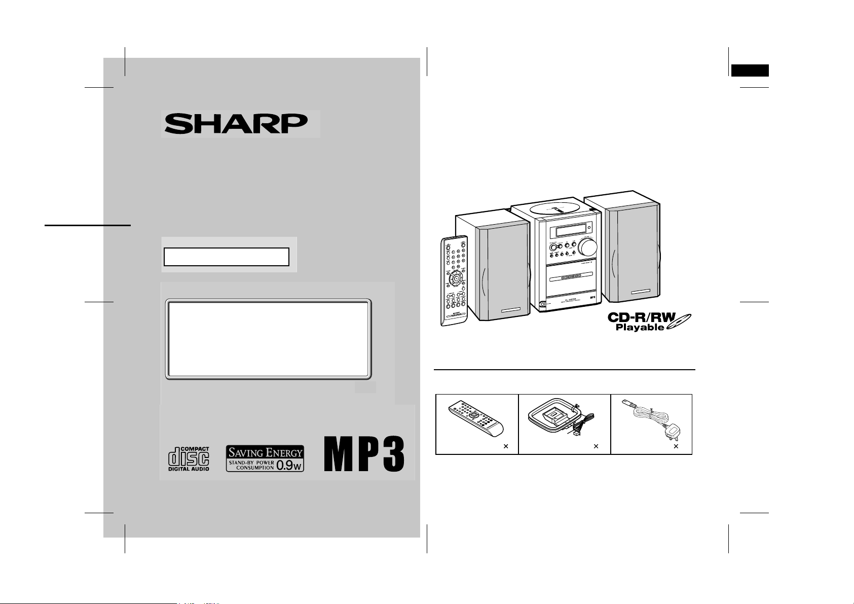
XL-MP35H Micro Component System consisting of XL-MP35H (main
unit) and CP-XL45H (speaker system).
Accessories
Please confirm that the following accessories are included.
Remote control 1 FM/AM loop aerial 1 AC power lead 1
Note:
Only the above accessories are included.
03/8/20 XL-MP35H(E)_FRONT.fm
TINSE0144SJZZ

XL-MP35H
Important Instruction
Special notes
NOTES FOR USERS IN THE U.K. AND IRELAND
The mains lead of this product is fitted with a non-rewireable
(moulded) plug incorporating a 3A fuse. Should the fuse need to
be replaced, a BSI or ASTA approved BS 1362 fuse marked
and of the same rating as above, which is also indicated on
the pin face of the plug must be used.
Always refit the fuse cover after replacing the fuse. Never use
the plug without the fuse cover fitted.
In the unlikely event of the socket outlet in your home not being
compatible with the plug supplied, cut-off the mains plug and fit
an appropriate type.
DANGER:
The fuse from the cut-off plug should be removed and the cut-off
plug destroyed immediately and disposed of in a safe manner.
Under no circumstances should the cut-off plug be inserted elsewhere into a 13A socket outlet as a serious electric shock may
occur.
To fit an appropriate plug to the mains lead, follow the instructions below:
IMPORTANT:
The wires in the mains lead are coloured in accordance with the
following code:
Blue : Neutral
Brown : Live
As the colours of the wires in the mains lead of this product may
not correspond with the coloured markings identifying the terminals in your plug, proceed as follows:
● The wire which is coloured blue must be connected to the plug
terminal which is marked N or coloured black.
● The wire which is coloured brown must be connected to the
plug terminal which is marked L or coloured red.
Ensure that neither the brown nor the blue wire is connected to
the earth terminal in your three pin plug.
or
Before replacing the plug cover, make sure that:
● If the new fitted plug contains a fuse, its value is the same as
that removed from the cut-off plug.
● The cord grip is clamped over the sheath of the mains lead
and not simply over the lead wires.
IF YOU HAVE ANY DOUBT, CONSULT A QUALIFIED ELECTRICIAN.
SERVICE INFORMATION
In the unlikely event of your equipment requiring repair, please
contact the dealer or supplier from whom it was purchased. Where
this is not possible, please visit our web-site www. sharp.co.uk/
customersupport.
Customers without internet access may telephone 08705
274277 during office hours (or (01) 676 0648 if telephoning
from lreland).
Please note; all calls will be charged at local rate.
Certain replacement parts and accessories may be obtained from
our main parts distributor.
WILLOW VALE ELECTRONICS LTD.
In the unlikely event of this equipment requiring repair during the
guarantee period, you will need to provide proof of the date of
purchase to the repairing company.
Please keep your invoice or receipt, which is supplied at the
time of purchase.
0121 766 5414
0301
2
03/8/20 XL-MP35H(E)1.fm
TINSE0144SJZZ
Contents
XL-MP35H
WARNINGS
When the ON/STAND-BY button is set at STAND-BY position,
!
mains voltage is still present inside the unit. When the ON/
STAND-BY button is set at STAND-BY position, the unit may be
brought into operation by the timer mode or remote control.
This unit contains no user serviceable parts. Never remove cov-
!
ers unless qualified to do so. This unit contains dangerous voltages, always remove mains plug from the socket before any
service operation and when not in use for a long period.
To prevent fire or shock hazard, do not expose this appliance to
!
dripping or splashing. No objects filled with liquids, such as
vases, should be placed on the apparatus.
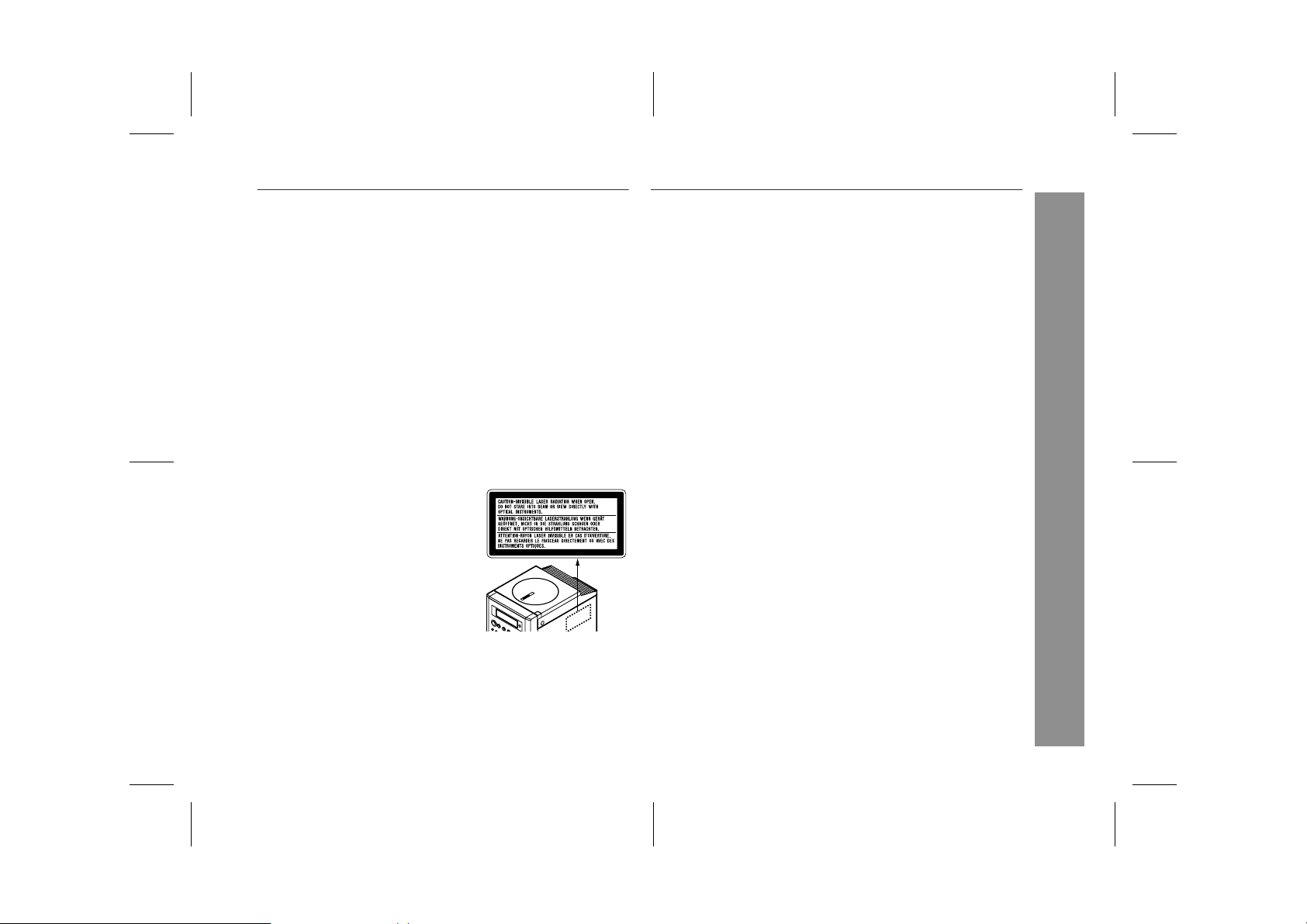
CAUTION
This product is classified as a CLASS 1 LASER product.
!
Use of controls, adjustments or performance of procedures other
!
than those specified herein may result in hazardous radiation
exposure.
As the laser beam used in this compact disc player is harmful to
the eyes, do not attempt to disassemble the cabinet. Refer servicing to qualified personnel only.
Laser Diode Properties
Material: GaAIAs
Wavelength: 780 nm
Emission Duration: continuous
Laser Output: max. 0.6 mW
NOTES
Recording and playback of any material may require consent, which
!
SHARP is unable to give. Please refer particularly to the provisions
of the Copyright Act 1956, the Dramatic and Musical Performers
Protection Act 1958, the Performers Protection Acts 1963 and 1972
and to any subsequent statutory enactments and orders.
This equipment complies with the requirements of Directives 89/
!
336/EEC and 73/23/EEC as amended by 93/68/EEC.
Page
"
General Information
Precautions . . . . . . . . . . . . . . . . . . . . . . . . . . . . . . . . . . . . . . . . . 4
Controls and indicators . . . . . . . . . . . . . . . . . . . . . . . . . . . . . 5, 6
"
Preparation for Use
Remote control . . . . . . . . . . . . . . . . . . . . . . . . . . . . . . . . . . . . . . 7
System connections . . . . . . . . . . . . . . . . . . . . . . . . . . . . . . . . 8, 9
"
Basic Operation
Sound control . . . . . . . . . . . . . . . . . . . . . . . . . . . . . . . . . . . . . . 10
Setting the clock . . . . . . . . . . . . . . . . . . . . . . . . . . . . . . . . . . . . 11
"
CD or MP3 disc Playback
Listening to a CD or MP3 disc . . . . . . . . . . . . . . . . . . . . . . 12, 13
Advanced CD or MP3 disc playback . . . . . . . . . . . . . . . . . 14 - 16
"
Radio
Listening to the radio . . . . . . . . . . . . . . . . . . . . . . . . . . . . . . . . 17
Listening to the memorised station . . . . . . . . . . . . . . . . . . . . . 18
"
Tape Playback
Listening to a cassette tape . . . . . . . . . . . . . . . . . . . . . . . . . . . 19
" Tape Recording
Recording on a cassette tape . . . . . . . . . . . . . . . . . . . . . . . 20, 21
"
Advanced Features
Timer and sleep operation . . . . . . . . . . . . . . . . . . . . . . . . .22 - 24
Enhancing your system . . . . . . . . . . . . . . . . . . . . . . . . . . . . . . 24
"
References
Troubleshooting chart . . . . . . . . . . . . . . . . . . . . . . . . . . . . . 25, 26
Maintenance . . . . . . . . . . . . . . . . . . . . . . . . . . . . . . . . . . . . . . . . 26
Specifications . . . . . . . . . . . . . . . . . . . . . . . . . . . . . . . . . . . . . . 27
TERMS OF GUARANTEE . . . . . . . . . . . . . . . . . . . . . .Back cover
Important Instruction
3
03/8/20 XL-MP35H(E)1.fm
TINSE0144SJZZ
XL-MP35H
General Information
4
Precautions
"
General
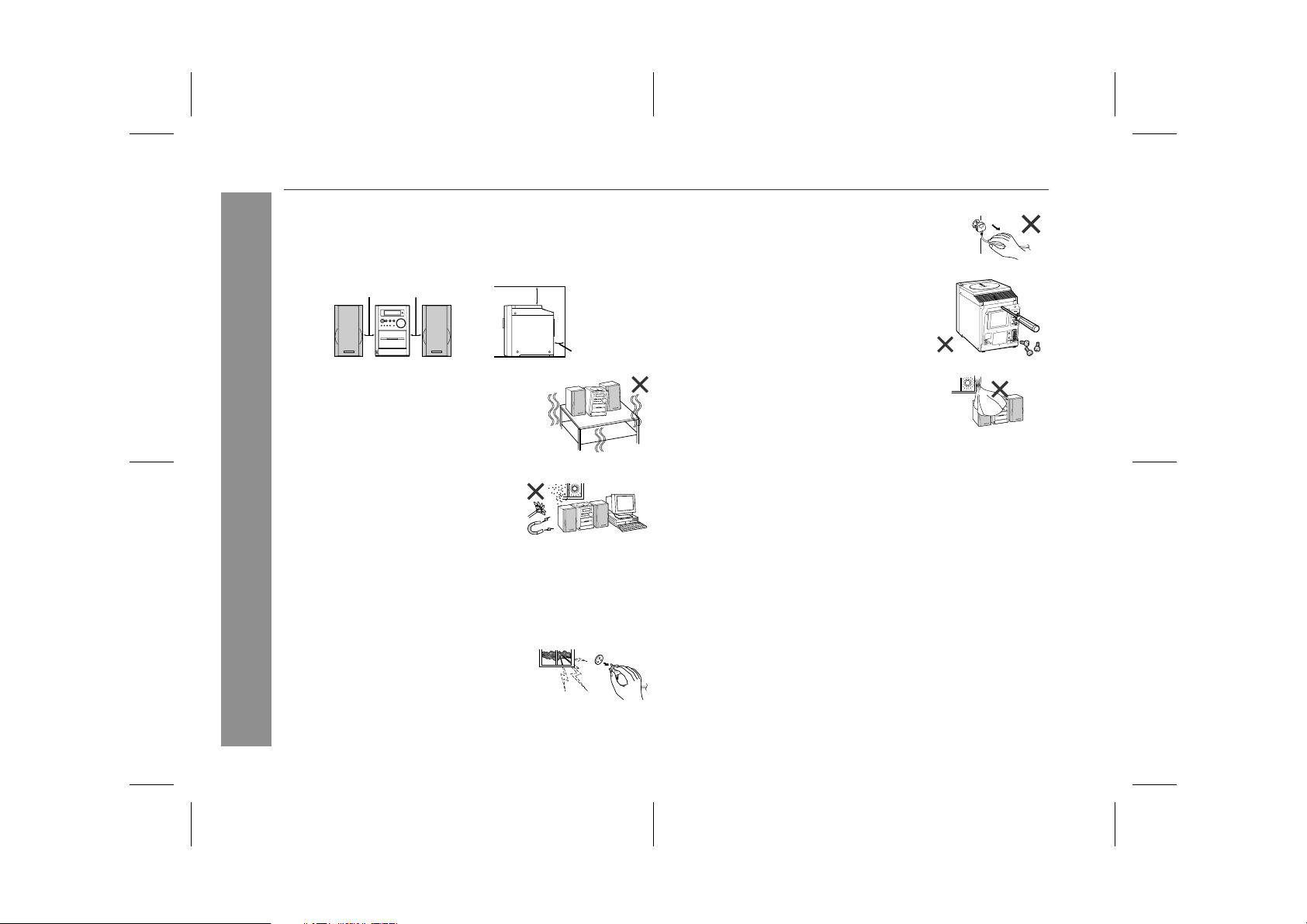
Please ensure that the equipment is positioned in a well venti-
!
lated area and that there is at least 10 cm (4") of free space along
the sides and back. There must also be a minimum of 20 cm (8")
of free space on the top of the unit.
10 cm (4") 10 cm (4")
Use the unit on a firm, level surface free from
!
vibration.
Keep the unit away from direct sunlight,
!
strong magnetic fields, excessive dust,
humidity and electronic/electrical equipment (home computers, facsimiles, etc.)
which generate electrical noise.
Do not place anything on top of the unit.
!
Do not expose the unit to moisture, to temperatures higher than
!
60°C (140°F) or to extremely low temperatures.
If your system does not work properly, disconnect the AC power
!
lead from the wall socket. Plug the AC power lead back in, and
then turn on your system.
In case of an electrical storm, unplug the
!
unit for safety.
20 cm (8")
10 cm (4")
Hold the AC power plug by the head when
!
removing it from the wall socket, as pulling
the lead can damage internal wires.
!
Do not remove the outer cover, as this
may result in electric shock. Refer internal service to your local SHARP service
facility.
The ventilation should not be impeded by
!
covering the ventilation openings with
items, such as newspapers, tablecloths,
curtains, etc.
No naked flame sources, such as lighted candles, should be
!
placed on the apparatus.
Attention should be drawn to the environmental aspects of bat-
!
tery disposal.
The apparatus is designed for use in moderate climate.
!
This unit should only be used within the range of 5°C - 35°C
!
(41°F - 95°F).
Warning:
The voltage used must be the same as that specified on this unit.
!
Using this product with a higher voltage other than that which is
specified is dangerous and may result in a fire or other type of
accident causing damage. SHARP will not be held responsible
for any damage resulting from use of this unit with a voltage other
than that which is specified.
!
CD players use a laser pickup which can damage the eyes if
viewed directly. Do not look at the pickup, and do not touch
the pickup directly.
" Volume control
The sound level at a given volume setting depends on speaker efficiency, location, and various other factors. It is advisable to avoid
exposure to high volume levels. Do not turn the volume on to full at
switch on and listen to music at moderate levels.
03/8/20 XL-MP35H(E)1.fm
TINSE0144SJZZ
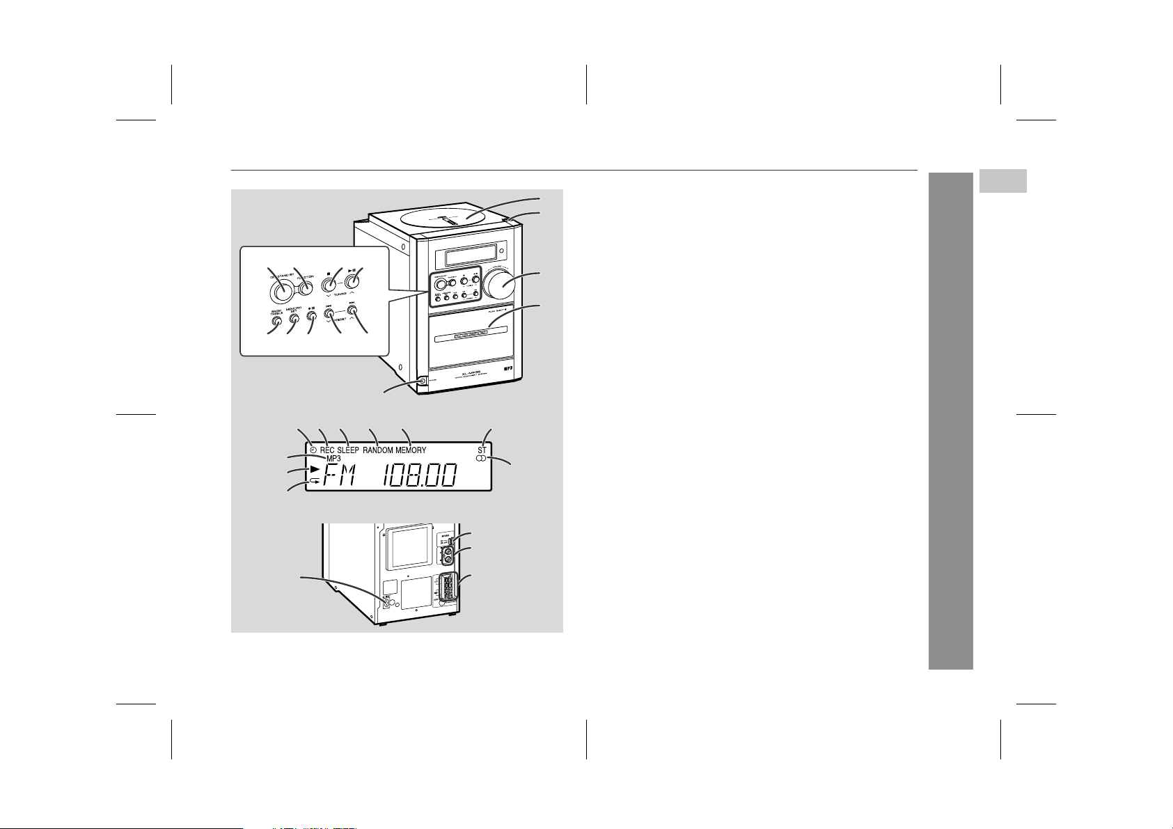
Controls and indicators
XL-MP35H
610789
11 12 13 14
5
15
17 18 19
16
22
23
24
25
26
27
28
20
21
1
2
3
4
1. Disc Compartment . . . . . . . . . . . . . . . . . . . . . . . . . . . . . . . 12
2. Disc Eject Button . . . . . . . . . . . . . . . . . . . . . . . . . . . . . . . . 12
3. Volume Control . . . . . . . . . . . . . . . . . . . . . . . . . . . . . . . . . . 10
4. Cassette Compartment . . . . . . . . . . . . . . . . . . . . . . . . . . . . 19
5. Headphone Socket . . . . . . . . . . . . . . . . . . . . . . . . . . . . . . . . 13
6. On/Stand-by Button . . . . . . . . . . . . . . . . . . . . . . . . . . . . . . . . 9
7. Function Selector Button . . . . . . . . . . . . . . . . . 12, 17, 19, 24
8. Disc or Tape Stop, Tuning Down Button . . . . . . . . 13, 17, 19
9. Disc Play or Pause, Tape Play,
Tuning Up Button . . . . . . . . . . . . . . . . . . . . . . . . 12, 13, 17, 19
10. Bass/Treble Selector Button . . . . . . . . . . . . . . . . . . . . . . . . 10
11. Memory/Set Button . . . . . . . . . . . . . . . . . . . . . . . . . . . . 16, 18
12. Tape Record Pause Button . . . . . . . . . . . . . . . . . . . . . . 20, 21
13. Disc Track Down or Fast Reverse, Tape Rewind,
Tuner Preset Down Button . . . . . . . . . . . . . . . . . . . 14, 18, 19
14. Disc Track Up or Fast Forward, Tape Fast Forward,
Tuner Preset Up Button . . . . . . . . . . . . . . . . . . . . . . 14, 18, 19
15. Timer Play Indicator
16. Tape Record Indicator
17. Sleep Indicator
18. Disc Random Indicator
19. Memory Indicator
20. FM Stereo Mode Indicator
21. FM Stereo Receiving Indicator
22. MP3 Disc Indicator
23. Disc Play Indicator
24. Disc Repeat Indicator
25. AC Power Input Socket . . . . . . . . . . . . . . . . . . . . . . . . . . . 8, 9
26. FM/AM Loop Aerial Socket . . . . . . . . . . . . . . . . . . . . . . . . 8, 9
27. Video/Auxiliary (Audio Signal) Input Sockets . . . . . . . . . . 24
28. Speaker Terminals . . . . . . . . . . . . . . . . . . . . . . . . . . . . . . . 8, 9
Reference page
1
General Information
03/8/20 XL-MP35H(E)1.fm
5
TINSE0144SJZZ
XL-MP35H
General Information
Controls and indicators (continued)
2
3
4
5
6
7
8
9
10
11
12
13
14
15
16
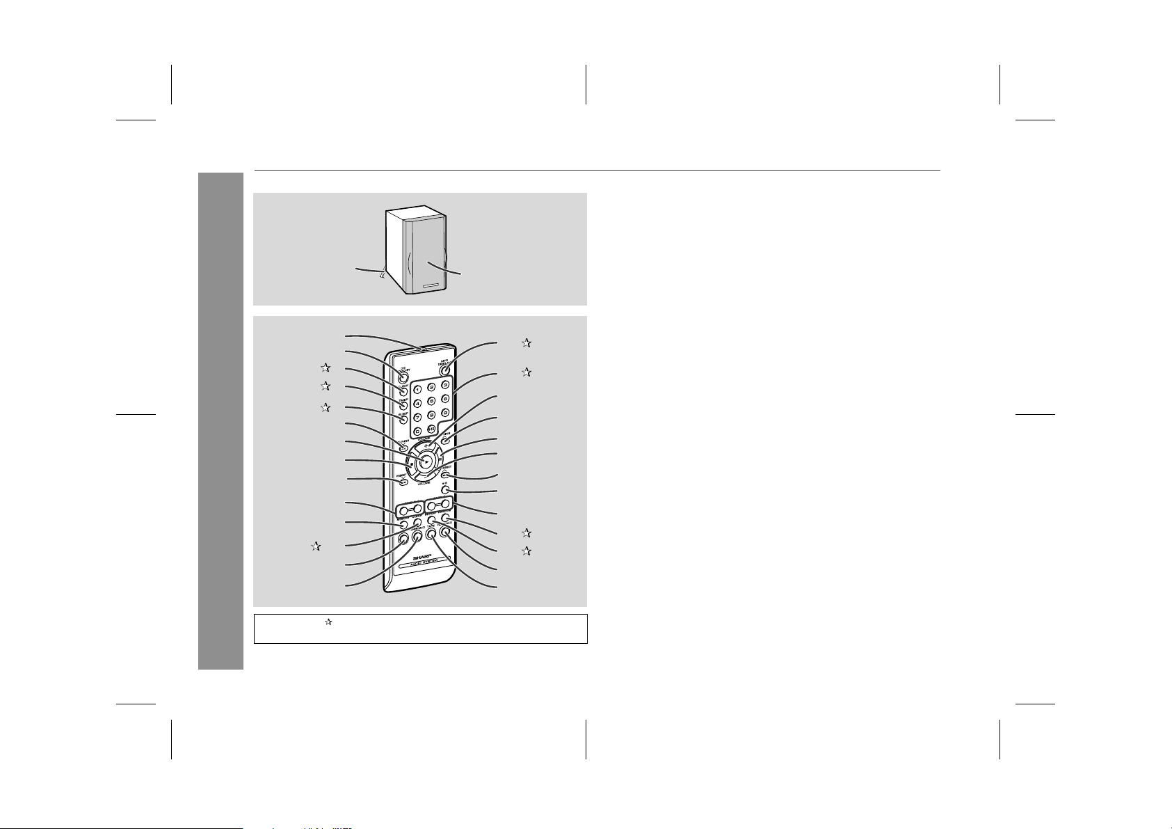
Buttons with " " mark in the illustration or highlighted in bold on the
right can be operated on the remote control only.
1
17
18
19
20
21
22
23
24
25
26
27
28
29
1. Full-Range Speaker
2. Speaker Wire
Reference page
3. Remote Control Transmitter . . . . . . . . . . . . . . . . . . . . . . . . . . . 7
4. On/Stand-by Button . . . . . . . . . . . . . . . . . . . . . . . . . . . . . . . . . 7
5. Clock Button . . . . . . . . . . . . . . . . . . . . . . . . . . . . . . . . . . . . . 11
6. Timer Button . . . . . . . . . . . . . . . . . . . . . . . . . . . . . . . . . . . . . 22
7. Sleep Button . . . . . . . . . . . . . . . . . . . . . . . . . . . . . . . . . . . . . 23
8. Disc Fast Reverse, Tuning Down,
Tape Rewind Button . . . . . . . . . . . . . . . . . . . . . . . . . . 14, 17, 19
9. Disc or Tape Play Button . . . . . . . . . . . . . . . . . . . . . . . . . 12, 19
10. Disc or Tape Stop Button . . . . . . . . . . . . . . . . . . . . . . . . . 13, 19
11. Disc Track Down, Tuner Preset Down Button . . . . . . 11, 14, 18
12. Treble Up and Down Buttons . . . . . . . . . . . . . . . . . . . . . . . . . 10
13. Memory Button . . . . . . . . . . . . . . . . . . . . . . . . . . . . . . 11, 16, 18
14. Programme Clear Button . . . . . . . . . . . . . . . . . . . . . . . . 16, 18
15. CD/MP3 Disc Button . . . . . . . . . . . . . . . . . . . . . . . . . . . . . . . 12
16. Tuner and Band Selector Button . . . . . . . . . . . . . . . . . . . . . . 17
17. MP3 Disc Display Button . . . . . . . . . . . . . . . . . . . . . . . . . . . 13
18. Direct Search Buttons . . . . . . . . . . . . . . . . . . . . . . . . . . . . . 15
19. Volume Up Button . . . . . . . . . . . . . . . . . . . . . . . . . . . . . . 10, 22
20. Disc Fast Forward, Tuning Up,
Tape Fast Forward Button . . . . . . . . . . . . . . . . . . . . . 14, 17, 19
21. Disc Pause Button . . . . . . . . . . . . . . . . . . . . . . . . . . . . . . . . . 13
22. Volume Down Button . . . . . . . . . . . . . . . . . . . . . . . . . . . . 10, 22
23. Disc Track Up, Tuner Preset Up Button . . . . . . . . . . . 11, 14, 18
24. Tape Record Pause Button . . . . . . . . . . . . . . . . . . . . . . . 20, 21
25. Bass Up and Down Buttons . . . . . . . . . . . . . . . . . . . . . . . . . . 10
26. Disc Random Button . . . . . . . . . . . . . . . . . . . . . . . . . . . . . . 15
27. Disc Repeat Button . . . . . . . . . . . . . . . . . . . . . . . . . . . . . . . 15
28. Video/Auxiliary Button . . . . . . . . . . . . . . . . . . . . . . . . . . . . . . 24
29. Tape Button . . . . . . . . . . . . . . . . . . . . . . . . . . . . . . . . . . . . . . 19
6
03/8/20 XL-MP35H(E)1.fm
TINSE0144SJZZ
XL-MP35H(E) TINSE0144SJZZ
2
Remote control
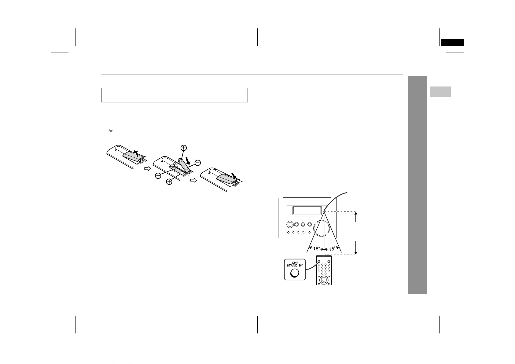
! Battery installation
Use 2 "AA" size batteries (UM/SUM-3, R6, HP-7 or similar).
Batteries are not included.
1 Remove the battery cover.
2 Insert the batteries according to the direction indicated in
the battery compartment.
When inserting or removing the batteries, push them towards the
battery terminals.
3 Replace the cover.
Precautions for battery use:
Replace all old batteries with new ones at the same time.
"
Do not mix old and new batteries.
"
Remove the batteries if the unit is not to be used for long periods
"
of time. This will prevent potential damage due to battery leakage.
Caution:
Do not use rechargeable batteries (nickel-cadmium battery, etc.).
"
Installing the batteries incorrectly may cause the unit to malfunc-
"
tion.
Notes concerning use:
Replace the batteries if the operating distance is reduced or if the
"
operation becomes erratic.
Periodically clean the transmitter on the remote control and the
"
sensor on the unit with a soft cloth.
Exposing the sensor on the unit to strong light may interfere with
"
operation. Change the lighting or the direction of the unit.
Keep the remote control away from moisture, heat, shock, and
"
vibrations.
! Test of the remote control
Check the remote control after checking all the connections (see
pages 8 - 9).
Point the remote control directly at the remote sensor on the unit.
The remote control can be used within the range shown below:
Press the ON/STAND-BY button. Does the power turn on? Now,
you can enjoy music.
Remote sensor
0.2 m - 6 m
(8" - 20')
XL-MP35H
2
Preparation for Use
03/8/20 XL-MP35H(E)1.fm
7
TINSE0144SJZZ
XL-MP35H
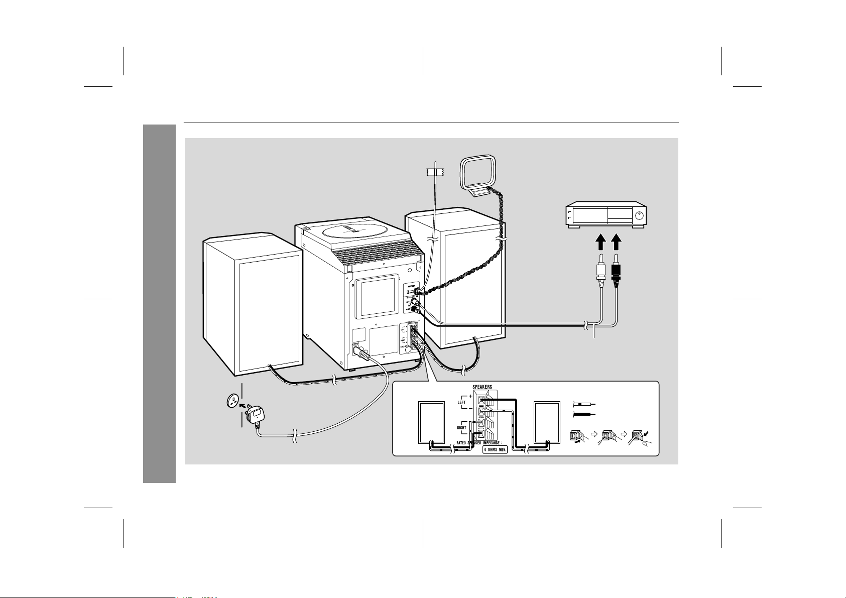
System connections
Preparation for Use
Right speaker
FM aerial
Right speaker
AM loop aerial
(See page 24.)
VCR, DVD, etc.
Left speaker
RCA lead
(not supplied)
Left speaker
White line
Plain
Wall socket
(AC 230 V, 50 Hz)
8
03/8/20 XL-MP35H(E)1.fm
TINSE0144SJZZ
XL-MP35H
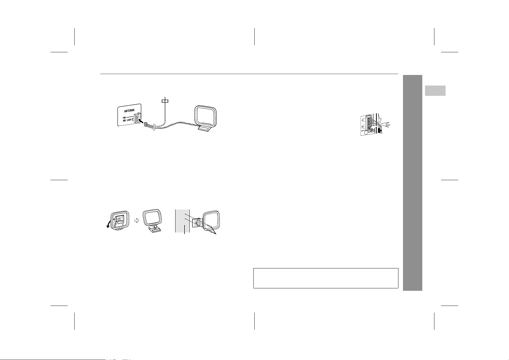
! Aerial connection
Connect the FM/AM loop aerial to the ANTENNA socket.
Position the FM aerial wire and rotate the AM loop aerial for optimum reception. Place the AM loop aerial on a shelf, or attach it to a
stand or a wall.
Notes:
Placing the aerial on the unit or near the AC power lead may
"
cause noise pickup. Place the aerial away from the unit for better
reception.
Do not connect the attached FM aerial to an external aerial as
"
this may cause trouble.
Installing the AM loop aerial:
< Assembling > < Attaching to the wall >
Wall Screws (not supplied)
! Speaker connection
Connect the wire with the white line to the minus (-) terminal and the
plain wire to the plus (+) terminal.
Caution:
Use speakers with an impedance of 4 ohms
"
or more, as lower impedance speakers can
damage the unit.
Do not mistake the right and the left chan-
"
nels. The right speaker is the one on the right
side when you face the unit.
Do not let the bare speaker wires touch
"
each other.
Placing the speaker system:
There is no distinction between the right and the left speakers.
Note:
The speaker grilles are not removable.
Incorrect
! Connecting the AC power lead
After checking all the connections have been made correctly, connect the AC power lead to the AC power input socket, then plug the
AC power lead of this unit into the wall socket.
Notes:
Unplug the AC power lead from the wall socket if the unit will not
"
be in use for a prolonged period of time.
Never use a power lead other than the one supplied. Otherwise,
"
a malfunction or an accident may occur.
! To turn the power on
Press the ON/STAND-BY button to turn the power on.
2
Preparation for Use
After use:
Press the ON/STAND-BY button to enter the power stand-by
mode.
03/8/20 XL-MP35H(E)1.fm
TINSE0144SJZZ
9
 Loading...