

Sharp XL-520W,CP-520 Service Manual
– 1 –
XL-520W/CP-520
CONTENTS
Page
SAFETY PRECAUTION FOR SERVICE MANUAL ........................................................................................................... 2
SPECIFICATIONS ............................................................................................................................................................. 2
NAMES OF PARTS ........................................................................................................................................................... 3
OPERATION MANUAL ...................................................................................................................................................... 5
DISASSEMBLY.................................................................................................................................................................. 7
REMOVING AND REINSTALLING THE MAIN PARTS..................................................................................................... 8
ADJUSTMENT ................................................................................................................................................................... 9
BLOCK DIAGRAM ........................................................................................................................................................... 16
SCHEMATIC DIAGRAM / WIRING SIDE OF P.W.BOARD............................................................................................. 20
VOLTAGE ........................................................................................................................................................................ 28
NOTES ON SCHEMATIC DIAGRAM .............................................................................................................................. 29
TYPE OF TRANSISTOR AND LED ................................................................................................................................. 29
WAVEFORMS OF CD CIRCUIT...................................................................................................................................... 30
TROUBLESHOOTING (CD SECTION) ........................................................................................................................... 31
FUNCTION TABLE OF IC................................................................................................................................................ 36
REPLACEMENT PARTS LIST/EXPLODED VIEW
XL-520W
CP-520
XL-520W and CP-520 constitute XL-520W.
SERVICE MANUAL
SHARP CORPORATION
No. S0780XL520W//
• In the interests of user-safety the set should be restored to its original
condition and only parts identical to those specified should be used.
This document has been published to be used
for after sales service only.
The contents are subject to change without notice.
XL-520W/CP-520
– 2 –
Cassette deck section
Frequency response: 50 - 14,000 Hz (Normal tape)
Signal/noise ratio: 50 dB
Wow and flutter: 0.25 % (WRMS)
Type: 2-way [12 cm (4-3/4") woofer and 2 cm
(13/16") tweeter]
Rated input power: 20 W
Maximum input power: 40 W
Impedance: 4 ohms
Dimensions: Width; 160 mm (6-5/16")
Height; 240 mm (9-1/2")
Depth; 183 mm (7-1/4")
Weight: 1.8 kg (4.0 lbs.)/each
General
Power source: AC110/127/220/230-240 V, 50/60 Hz
Power consumption: 98 W
Dimensions: Width; 160 mm (6-5/16")
Height; 240 mm (9-1/2")
Depth; 300 mm (11-13/16")
Weight: 3.7 kg (8.2 lbs.)
Amplifier section
Output power: PMPO; 320 W (total)
MPO; 56 W (28 W + 28 W) (10% T.H.D)
RMS; 40 W (20 W + 20 W) (10% T.H.D)
Input terminals: Video/Auxiliary (audio signal);
500 mV/47 kohms
Output terminals: Speakers; 4 ohms
Headphones; 16-50 ohms
(recommended; 32 ohms)
Tuner section
Frequency range: FM; 88 - 108 MHz
AM; 531 - 1,602 kHz
Compact disc player section
Type: Compact disc player
Signal readout: Non-contact, 3-beam semi-conductor
laser pickup
D/A Converter: 1-bit D/A converter
Filter: 8-times oversampling digital filter
Frequency response: 20 - 20,000 Hz
Wow and flutter: Unmeasurable
(less than 0.001% W.peak)
SPECIFICATIONS
SAFETY PRECAUTION FOR
SERVICE MANUAL
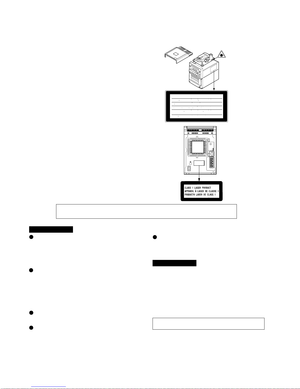
Precaution to be taken when replacing and servicing the
Laser Pickup.
The AEL (Accessible Emission Level) of Laser Power Output
for this model is specified to be lower than Class I Requirements.
However, the following precautions must be observed during
servicing to protect your eyes against exposure to the Laser
beam
(1) When the cabinet has been removed, the power is turned
on without a compact disc, and the Pickup is on a position
outer than the lead-in position, the Laser will light for several
seconds to detect a disc. Do not look into the Pickup Lens.
(2) The Laser Power Output of the Pickup inside the unit and
replacement service parts have already been adjusted prior
to shipping.
(3) No adjustment to the Laser Power should be attempted
when replacing or servicing the Pickup.
(4) Under no circumstances look directly into the Pickup Lens
at any time.
(5) CAUTION - Use of controls or adjustments, or performance
of procedures other than those specified herein may result
in hazardous radiation exposure.
FOR A COMPLETE DESCRIPTION OF THE OPERATION OF THIS UNIT, PLEASE REFER
TO THE OPERATION MANUAL.
Specifications for this model are subject to change without
prior notice.
XL-520W
CAUTION-INVISIBLE LASER RADIATION WHEN OPEN. DO NOT STARE INTO
BEAM OR VIEW DIRECTLY WITH OPTICAL INSTRUMENTS.
VARNING-OSYNLIG LASERSTRALNING NAR DENNA DEL AR OPPNAD. STIRRA
EJ IN I STRALEN OCH BETRAKTA EJ STRALEN MED OPTISKA INSTRUMENT.
ADVERSEL-USYNLIG LASERSTRALING VED ABNING. SE IKKE IND I
STRALEN-HELLER IKKE MED OPTISKE INSTRUMENTER.
VARO! AVATTAESSA OLET ALTTIINA NAKYMATON LASERSATEILYLLE.
ALA TUIJOTA SATEESEEN ALAKA KATSO SITA OPTISEN LAITTEEN LAPI.
VARNING-OSYNLIG LASERSTRALNING NAR DENNA DEL AR OPPNAD.
STIRRA EJ IN I STRALEN OCH BETRAKTA EJ STRALEN GENOM OPTISKT
INSTRUMENT.
ADVERSEL-USYNLIG LASERSTRALING NAR DEKSEL APNES. STIRR IKKE
INN I STRALEN ELLER SE DIREKTE MED OPTISKE INSTRUMENTER.
Laeser Diode Properties
Material: GaAlAs
Wavelength: 780 nm
Emission Duration:continuous
Laser Output: max. 0.6 mW
CP-520
– 3 –
XL-520W/CP-520
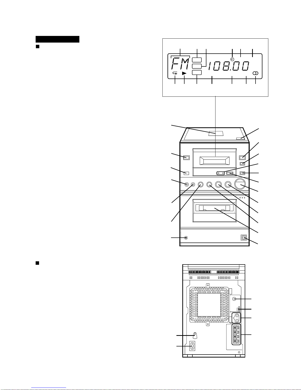
NAMES OF PARTS
Front Panel
1. Functin/Band/Track Number Indicator
2. Volume Indicator
3. Extra Bass/Equalizar Indicator
4. Timer Indicator
5. Record Indicator
6. Sleep Indicator
7. Repeat Indicator
8. Play Indicator
9. Video/Auxiliary Indicator
10. Random Indicator
11. Memory Indicator
12. FM Stereo Mode Indicator
13. FM Stereo Indicator
14. CD Compartment
15. On/Stand-by Switch
16. Remote Control Sensor
17. Record Pause/Beat Cancel Button
18. Memory/Set Button
19. (CD) Track Down/Review Button
(TAPE) Rewind Button
(TUNER) Preset Down Button
20. Headphone Socket
21. CD Eject Button
22. Function Selector Button
23. Band Selector Button
24. 3D Surround Mode Indicators
25. Extra Bass/Equalizer Mode Button
26. 3D Surround Mode Button
27. Volume Up/Down Buttons
28. (CD) Play/Pause Button
(TAPE) Play Button
(TUNER) Tuning Up Button
29. (CD/TAPE) Stop Button
(TUNER) Clear Button
30. (CD) Track Up/Cue Button
(TAPE) Fast Forward Button
(TUNER) Preset Up Button
31. Cassette Compartment
32. CD Digital Output Socket (Optical)
Rear Panel
1. AC Voltage Selector
2. AC Power Input Socket
3. FM 75 ohms Aerial Socket
4. AM Loop Aerial Input Socket
5. Video/Auxiliary (Audio Signal) Input Sockets
6. Speaker Terminals
XL-520W
VOL
EQ
AUX
RANDOM MEMORY ST
REC SLEEP
kHz
MHz
123 456
8 9 10 11 12 137
14
15
16
17
18
19
20
21
22
23
24
25
26
27
28
29
30
31
32
1
2
3
4
5
6
XL-520W/CP-520
– 4 –
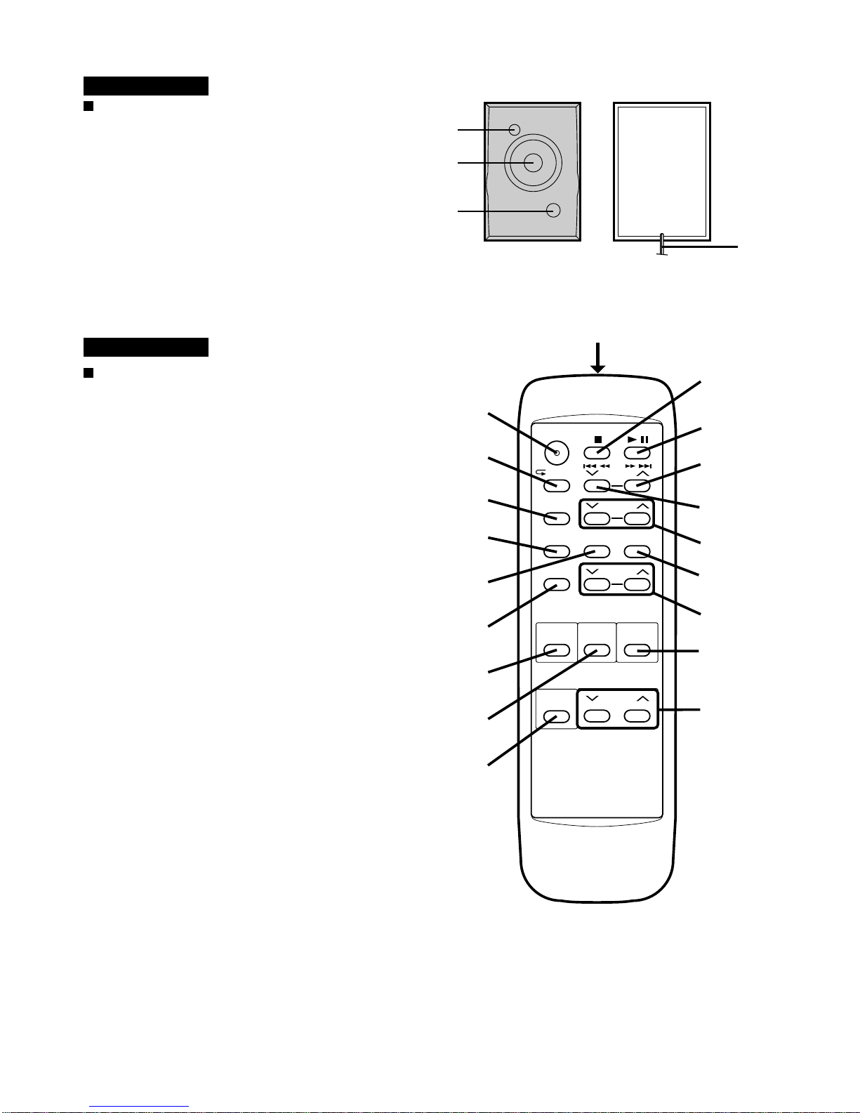
Speaker Section
1. Tweeter
2. Woofer
3. Bass Reflex Duct
4. Speaker Wire
Remote Control
1. Remote Control Transmitter LED
2. On/Stand-by Button
3. (CD) Repeat/Random Button
4. (CD/TUNER) Memory/Set Button
5. (CD/TUNER) Clear Button
6. Timer/Set Button
7. Sleep Button
8. (CD/TAPE) Stop Button
9. (CD) Play/Pause Button
(TAPE) Play Button
10. (CD) Track Up/Cue Button
(TAPE) Fast Forward Button
(TUNER) Preset Up Button
11. (CD) Track Down/Review Button
(TAPE) Rewind Button
(TUNER) Preset Down Button
12. Tuning Up/Down Buttons
13. Timer Button
14. Timer Up/Down Buttons
15. Function Selector Button
16. Band Selector Button
17. 3D Surround Mode button
18. Extra Bass/Equalizer Mode Button
19. Volume Up/Down Buttons
CP-520
XL-520W
1
2
3
4
ON/
STAND-BY
/RANDOM
TIMER/
SET
PRESET
MEMORY/
SET
TUNING
TIMER
VOLUME
CLEAR
SLEEP
FUNCTION
BAND
X-BASS/
EQUALIZER
TIMER
3D
SURROUND
1
8
9
10
11
12
13
14
18
19
2
3
4
5
6
7
15
16
17
– 5 –
XL-520W/CP-520
OPERATION MANUAL
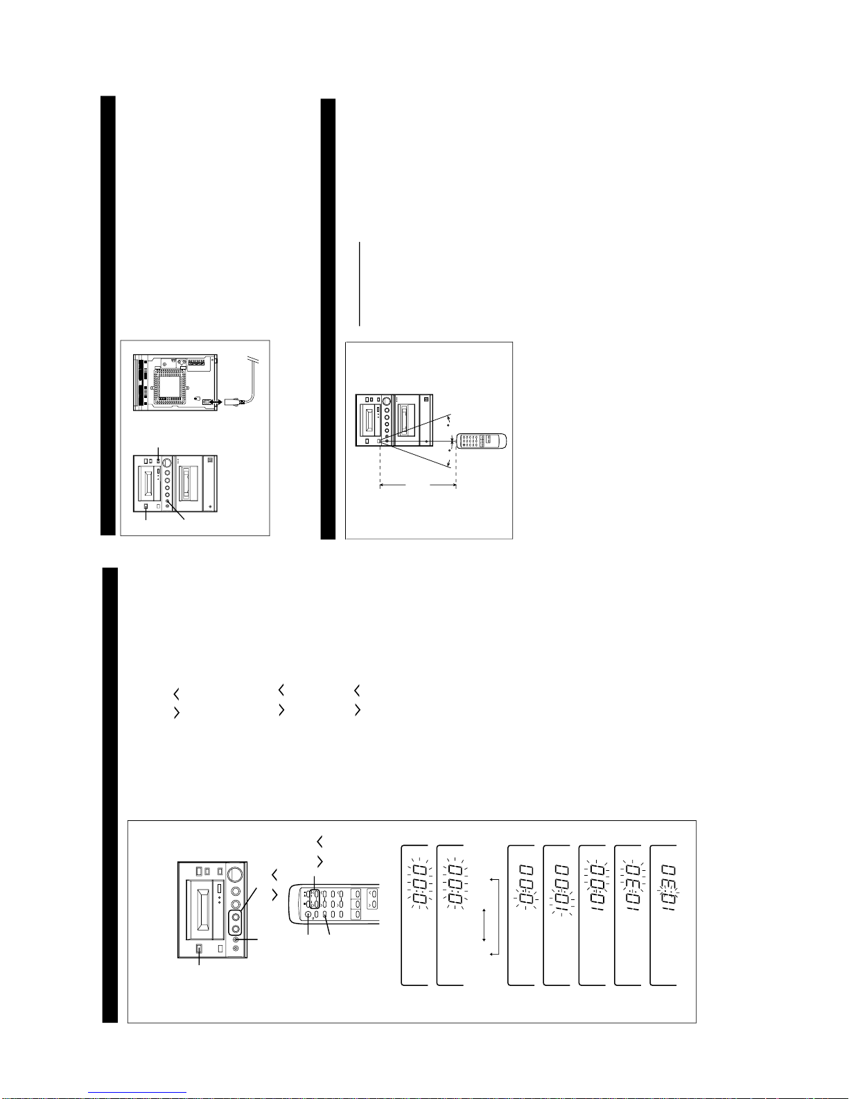
SETTING THE CLOCK
1
Press the ON/STAND-BY button to enter the stand-by mode.
2
Press the MEMORY/SET button.
3
Press the PRESET ( or ) button to select the time display
mode.
"0:00" → Th e 24-hour di splay will appe ar.
(0:00 - 23:59)
"AM 12:00" → The 12-hour display will appear.
(AM 12:00 - PM 11:59)
● Note that this can only be set when the unit is first installed
or it has been reset (see page 6).
4
Press the MEMORY/SET button.
5
Press the PRESET ( or ) button to adjust the hour.
● Press the PRESET button once to advance the time by 1 hour.
Hold it down to advance continuously.
● When the 12-hour display is selected, "AM" will change auto-
matically to "PM".
6
Press the MEMORY/SET button.
7
Press the PRESET ( or ) button to adjust the minutes.
● Press the PRESET button once to advance the time by 1
minute. Hold it down to change the time in 5 minute intervals.
● The hour setting will not advance even if minutes advance from
"59" to "00".
8
Press the MEMORY/SET button.
● The clock starts operating from "0" seconds. (Seconds are not
displayed.)
Note:
● In the event of a power failure or when the AC power lead is
disconnected, the clock display will go out.
When the AC power supply is restored, the clock display will
flash on and off to indicate the time when the power failure
occurred or when the AC power lead was disconnected.
ON/
STAND-BY
ON/
STAND-BY
MEMORY/
SET
MEMORY/
SET
PRESET
( / )
PRESET
( / )
AM 12:000:00
2
3
4
5
6
7
8
If this happens, follow the procedure below to change the clock
time.
To change the clock time:
1
Press the ON/STAND-BY button to enter the stand-by mode.
2
Perform steps 4 - 8 above.
To change the time display mode:
1
Perform steps 1 - 3 in the section "RESETTING THE MICRO-
COMPUTER", on page 6.
2
Perform steps 1 - 8 above.
In this example, the clock is set for the 24-hour
(0:00) system.
PREPARATION FOR USE
15
15
■
Remote control
Notes concerning use:
● Replace the batteries if control distance decreases or operation
becomes erratic.
● Periodically clean the transmitter LED on the remote control
and the sensor on the main unit with a soft cloth.
● Exposing the sensor on the main unit to strong light may in-
terfere with operation. Change the lighting or the direction of
the unit.
● Keep the remote control away from moisture, excessive heat,
shock, and vibrations.
0.2 m - 6 m
(8" - 20')
RESETTING THE MICROCOMPUTER
Reset the microcomputer under the following conditions:
● To erase all of the stored memory contents (clock and timer
settings, tuner and CD presets).
● If the display is not correct.
● If the operation is not correct.
1
Press the ON/STAND-BY button to enter the stand-by mode.
2
Unplug the AC power lead from the AC INPUT socket on this
unit.3Whilst pressing down the MEMORY/SET button and the X-
BASS/EQUALIZER button, plug the AC power lead into the
AC INPUT socket on this unit.
1
2,3
3
3
Caution:
● The operation explained above will erase all data stored in
memory, such as clock and timer settings, tuner and CD pres-
ets.

XL-520W/CP-520
– 6 –
(Continued)
■
AM/FM interval (span)
The International Telecommunication Union (ITU) has established
that member countries should maintain either a 10 kHz or a 9
kHz interval between broadcasting frequencies of any AM station.
The illustration shows the 9 kHz interval zones (regions 1 and
3), and the 10 kHz interval zone (region 2).
This product is not equipped with a span selector. However, it
will be adjusted to 9 kHz AM interval (50 kHz FM interval) when
shipped from the factory.
Before using the unit, be sure to set it for the AM tuning interval
(span) used in your area.
To check the tuning span currently selected:
1
Press the ON/STAND-BY button to turn the power on.
2
Press the FUNCTION button until "FM" or "AM" appears in
the display.3Press the BAND button to select the AM band.
● If "AM 531 kHz" is displayed, it means that the radio has been
adjusted for a 9 kHz span. If "AM 530 kHz" is displayed, it
means that the radio has been adjusted for a 10 kHz span.
To change from a 9 kHz AM (50 kHz FM) interval to a
10 kHz AM (100 kHz FM) interval:
1
Press the ON/STAND-BY button to enter the stand-by mode.
2
Hold down the BAND button and the ■ button for at least 4
seconds. Release the buttons when "AM SP 10 kHz" and "FM
SP 100 kHz" are displayed alternately.
● The unit will return to the clock display.
To return to a 9 kHz AM (50 kHz FM) interval:
1
Press the ON/STAND-BY button to enter the stand-by mode.
2
Hold down the BAND button and the ■ button for at least 4
seconds. Release the buttons when "AM SP 9 kHz" and "FM
SP 50 kHz" are displayed alternately.
● The unit will return to the clock display.
Cautions:
● When the unit is left for approximately 14 hours after the span
has been switched and AC power lead disconnected, it will be
automatically returned to a 9 kHz span. If this happens, set
the span again.
● When the span is switched, any stations that are memorised
will be cancelled.
ON/
STAND-BY
BAND
FUNCTION
kHz
kHz
kHz
kHz
[9 kHz → 10 kHz]
[10 kHz → 9 kHz]
kHz
kHz
kHz
kHz
(4 seconds)
(4 seconds)
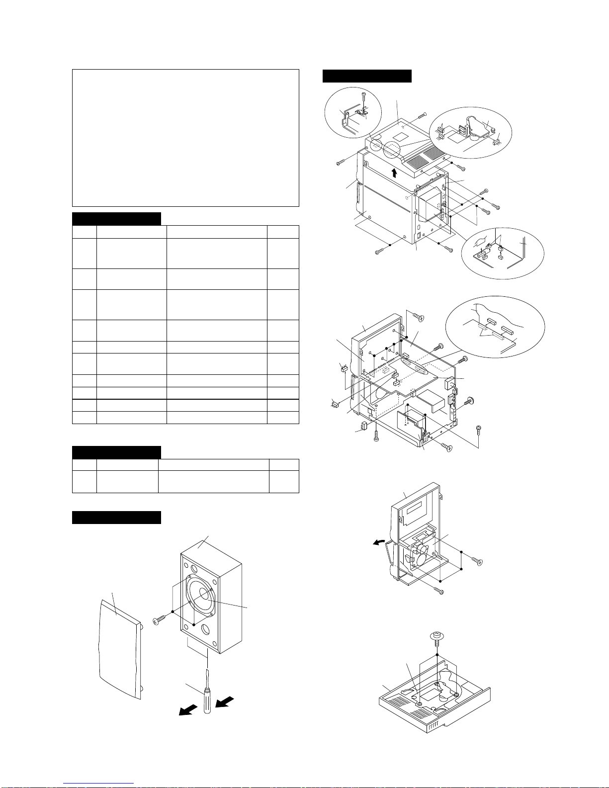
– 7 –
XL-520W/CP-520
1 Top Cabinet 1. Screw .................. (A1) x4 7-1
2. Socket ................. (A2) x3
3. Screw .................. (A3) x1
2 Side Panel 1. Screw .................. (B1) x7 7-1
(Left/Right)
3 Back Board 1. Screw .................. (C1) x4 7-1
(With Power 2. Socket ................. (C2) x2
Amp. PWB) 3. Flat Wire .............. (C3) x1
4 Main PWB 1. Screw .................. (D1) x3 7-2
2. Socket ................. (D2) x2
5 Front Panel 1. Screw .................. (E1) x2 7-2
6 Display PWB/ 1. Screw .................. (F1) x6 7-2
CD Servo PWB 2. Socket ................. (F2) x2
7 Power Supply PWB 1. Screw .................. (G1) x5 7-2
8 Jack PWB 1. Screw .................. (H1) x1 7-3
9 Tape Mechanism 1. Screw .................. (J1) x4 7-3
10 CD Mechanism 1. Screw .................. (K1) x3 7-4
DISASSEMBLY
Caution on Disassembly
Follow the below-mentioned notes when disassembling
the unit and reassembling it, to keep it safe and ensure
excellent performance:
1. Take cassette tape and compact disc out of the unit.
2. Be sure to remove the power supply plug from the wall
outlet before starting to disassemble the unit.
3. Take off nylon bands or wire holders where they need be
removed when disassembling the unit. After servicing
the unit, be sure to rearrange the leads where they were
before disassembling.
4. Take suffcient care on static electricity of integrated
circuits and other circuits when servicing.
Figure 7-2
Figure 7-3
STEP REMOVAL
PROCEDURE
FIGURE
Figure 7-1
XL-520W
STEP
REMOVAL PROCEDURE FIGURE
1 Woofer 1. Net........................... (A1) x1 7-5
3. Screw ...................... (A2) x4
CP-520
(A1)x1
ø3x12mm
(A1)x1
ø3x12mm
(B1)x2
ø3x10mm
(C1)x2
ø3x10mm
(B1)x2
ø3x10mm
(C1)x2
ø3x10mm
(C2)x2
(B1)x3
ø3x10mm
(A1)x2
ø3x10mm
(A2)x2
(A2)x1
CD
Mechanism
(A3)x1
ø3x10mm
Swicth
PWB
Top Cabinet
Top
Cabinet
Side Panel
(Right)
Front
Panel
Rear
Panel
Back
Board
Power Amp PWB
Side Panel
(Left)
(c3)x1
(F1)x6
ø3x10mm
(D1)x1
ø3x10mm
(D1)x1
ø3x10mm
CD Servo PWB
Main PWB
Power Supply
PWB
Front Panel
Display PWB
(G1)x4
ø4x6mm
(D1)x1
ø3x10mm
(G1)x1
ø3x10mm
(E1)x2
ø3x10mm
(F2)x1
(D2)x1
(D2)x1
(F2)x1
(D2)x2
CD Servo
PWB
Main
PWB
CD Mechanism
(K1)x3
ø2.6x10mm
Top Cabinet
(A2)x4
ø4x12mm
Net
(A1)x1
Woofer
Speaker Box
Screw
driver
Direction of handle
XL-520W
Figure 7-4
CP-520
Figure 7-5
Tape MechanismOpen
(J1)x4
ø3x10mm
Front Panel
(H1)x1
ø3x10mm
XL-520W/CP-520
– 8 –
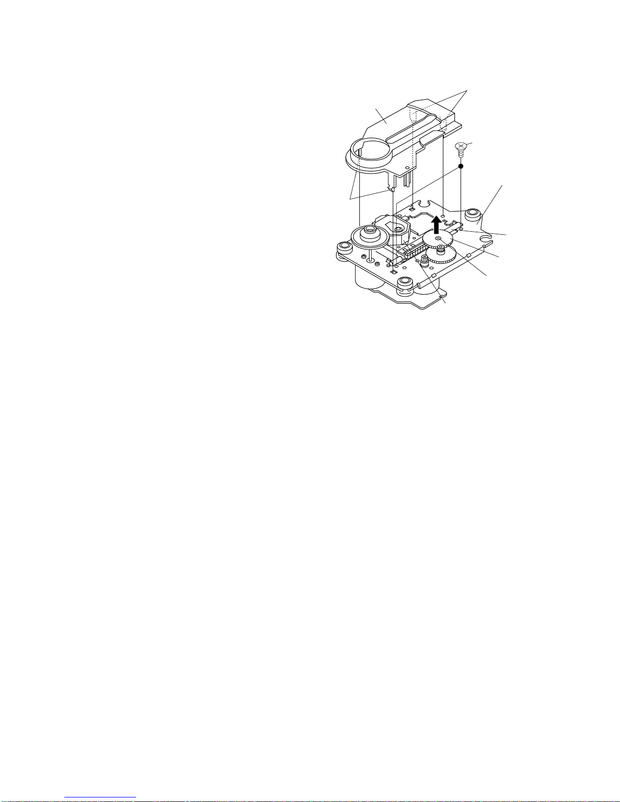
Figure 8
How to remove the pickup (See Fig. 8)
1. Remove the mechanism cover, paying attention to the
pawls (A1) x 4 pcs.
2. Remove the screws (A2) x 2 pcs., to remove the shaft (A3)
x 1 pc.
3. Remove the stop washer (A4) x 1 pc., to remove the gear
(A5) x 1 pc.
4. Remove the pickup.
Note:
After removing the optical pickup connector wrap the front
end of connector in conductive aluminium foil so as to
prevent damage of optical pickup by static electricity.
REMOVING AND REINSTALLING THE MAIN PARTS
CD MECHANISM SECTION
Perform steps 1,to 5 of the disassembly method to remove the
CD mechanism.
Pickup Unit
( A2 ) x2
ø2.6 x6mm
( A1 ) x2
CD Mechanism
Shaft
( A3 ) x1
Gear
( A5 ) x1
StopWasher
( A4 ) x1
Mechanism Cover
( A1 ) x2
– 9 –
XL-520W/CP-520
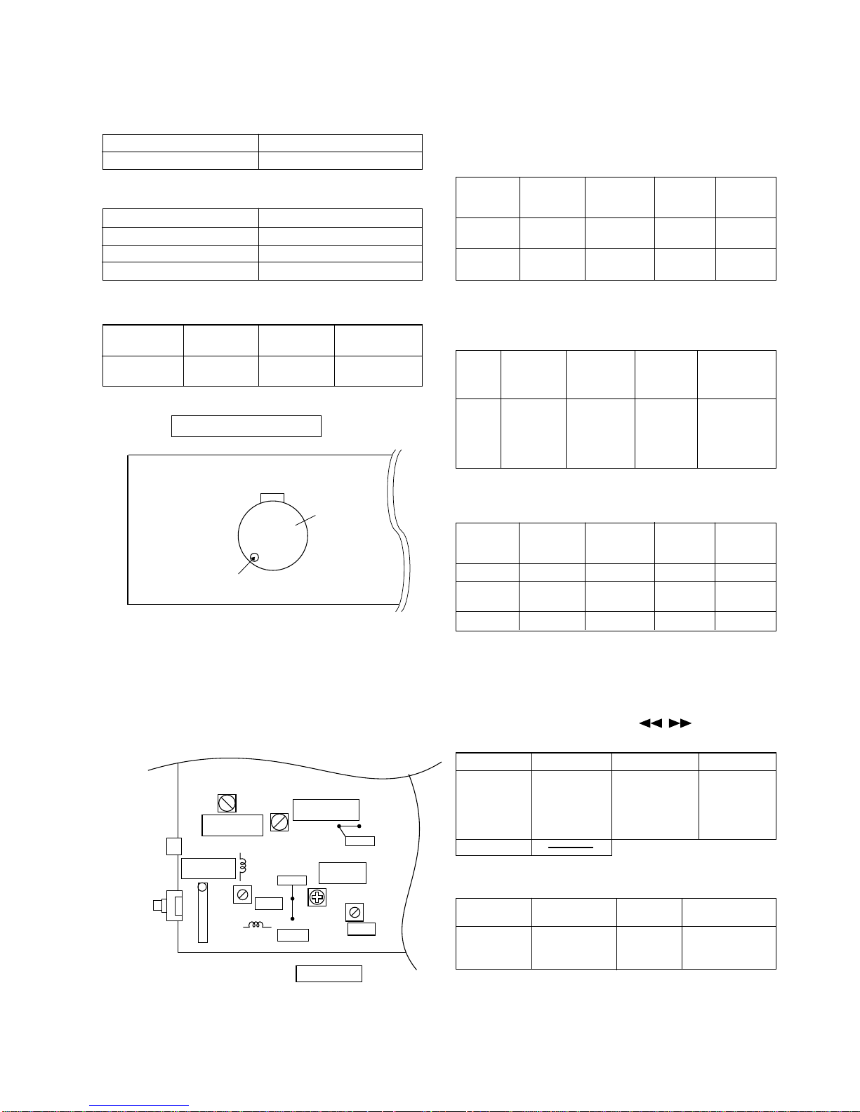
MECHANISM SECTION
• Driving Force Check
Torque Meter
Specified Value
Play: TW-2412 Over 80 g
• Torque Check
Torque Meter
Play: TW-2111 30 to 70 g. cm
Fast forward: TW-2231 50 to 140 g.cm
Rewind: TW-2231 50 to 140 g.cm
Specified
Value
Adjusting
Point
Instrument
Connection
Test Tape
MTT-111 Motor 3,000 ± Headphone
90 Hz Socket
ADJUSTMENT
Specified Value
• Tape Speed
Figure 9-1 ADJUSTMENT POINT
TAPE MECHANISM
M901
Motor
Volume in motor
Figure 9-2 ADJUSTMENT POINTS
SO301
ANTENNA
TERMINAL
MAIN PWB
CNP301
L302
IC301
1
T302
TP301
TP302
T304
FM IF
AM IF
AM
TRACKING fL
T306
AM BAND
COVERAGE fL
FM MUTE
LEVEL
T351
VR351
L303
FM BAND
COVERAGE fL
FM RF
fL: Low-range frequency
fH: High-renge frequency
IF 450 kHz 1,602 kHz T351 *1
Band — 531 kHz (fL): T306 *2
Coverage 1.1 ± 0.1 V
Tracking 990 kHz 990 kHz (fL): T302 *1
Test Stage
Frequency Frequency
Display
Setting/
Adjusting
Parts
Instrument
Connection
Adjusting
Parts
Instrument
Connection
Display
Frequency
98.00 MHz 98.00 MHz VR351* Input: SO301
(25 dBµV) Output: Speaker
Terminal
TUNER SECTION
• FM RF
Signal generator: 1 kHz, 75 kHz dev., FM modulated
Band — 87.50 MHz (fL): L303 *1
Coverage 3.4 ± 0.1 V
RF 98.00 MHz 98.00 MHz L302 *2
(10-30 dB)
Test Stage
Frequency
Frequency
Display
Setting/
Adjusting
Parts
Instrument
Connection
*1. Input: Antenna, Output: TP301
*2. Input: Antenna, Output: Speaker Terminal
• Detection
Signal generator: 10.7 MHz, FM sweep generator
IF 10.7 MHz 98.00 MHz T304(Turn Input: Pin 1 of
the core of IC301
T304 fully Output: TP302
counterclockwise.
Test
Stage
Frequency
Frequency
Display
Setting/
Adjusting
Parts
Instrument
Connection
*1. Input: Antenna, Output: Speaker Terminal
*2. Input: Input is not connected, Output: TP301
• Setting the Test Mode
Keeping the BAND button and MEMORY button pressed, turn
on POWER. Then, the frequency is initially set in the memory
as shown in Table. Call it with the , button to use it
for adjustment and check of tuner circuit.
Preset No.
FM
Preset No.
AM
1 87.50 MHz 6 531 kHz
2 108.00 MHz 7 1,602 kHz
3 98.00 MHz 8 990 kHz
4 90.00 MHz 9 603 kHz
5 106.00 MHz 10 1,404 kHz
11~40
• FM Mute Level
Signal generator: 1 kHz, 40 kHz dev., FM modulated
*Adjust so that an output signal appears.
• AM IF/RF
Signal generator: 400 Hz, 30%, AM modulated
XL-520W/CP-520
– 10 –
Figure 10-2
Figure 10-3
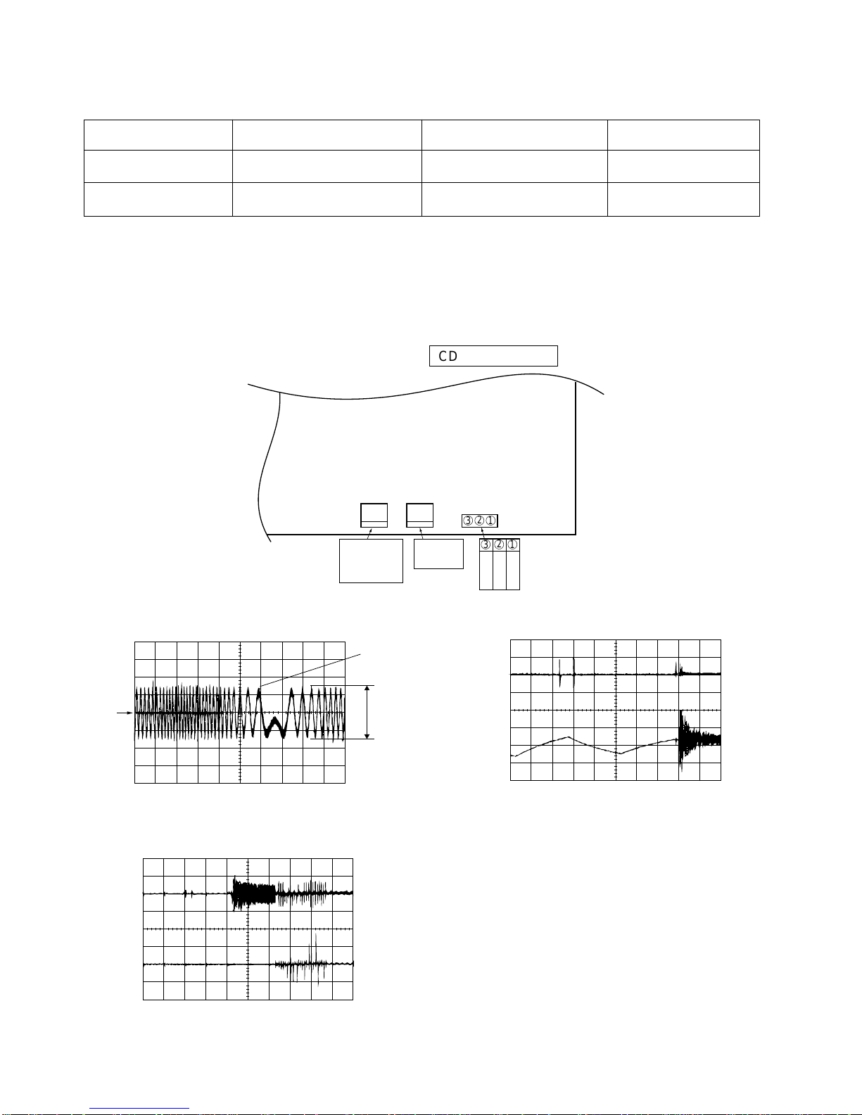
1. This CD unit need adjustment as follow.
CD SECTION
Figure 10-4
CD Test Mode
Adjustment Part
Value/Adjusting Method
Instrument Connection
Step 1 VR803 (Focus Offset) DC + 40 mV (FEI>VRO) FEI (R826) and VRO
(1-Pin of TP801)
Step 4 VR802 (Tracking Error Balance) *1 (See Fig. 9-2) TSO (3-Pin of TP801)
and VRO (1 Pin of TP801)
*1: Adjust to obtaiin vertically symmetrical waveform (Fig. 10-2) with respect toreference DC level. The reference level is VRO
(Approx DC 2.1V).
2. This CD unit have the following automatic adjustment function. Automatic adjustment item.
2-1: Focus Servo Gain (Fig. 10-3)
Focus Gain Adjustment is performed when disc is changed.
2-2: Tracking Servo Gain (Fig. 10-4)
Tracking Gain Adjustment is performed when disc is changed and disc is playbacked.
TSO
VRO
1
SYMMETRICAL
UP AND DOWN
FEI
FSO
1
2
TSO
TS2O
1
2
Figure 10-1 ADJUSTMENT POINTS
VR802 VR803
TP801
TRACKING
ERROR
BALANCE
FOCUS
OFFSET
T
S
O
N
C
V
R
O
321
321
CD SERVO PWB
– 11 –
XL-520W/CP-520
TEST MODE
The Test Mode for this microcomputer has two variations, namely "regular Test Mode" for adjustment and measurement and "selfdiagnosis Test Mode" for self-judgment in final inspection of products.
1. Entering the Test Mode
To enter the each Test Mode, press the POWER key, holding down the following two keys in the regular standby mode (power
off state). In this case only the main unit keys are valid. The Test Mode is not set even when the remote controller POWER
key is turned on.
[Regular Test Mode] [Holding Down Keys]
1. CD Test Mode (TEST 1)………………………… Stop + Play
2. Tuner Test Mode (TEST 3)……………………… Memory/Set + Band Selector
3. Electronic volume Test Mode (TEST 4)…………Stop + Extra Bass/Equalizer Mode
4. Timer Test Mode (TEST 5)……………………… Fast Forward + Function Selector
5. LCD Test Mode (TEST 6)…………………………Memory/Set + Function Selector
[Self-diagnosis Test Mode]
1. Key input diagnosis TEST Mode (TESTA)………Play + Record Pause
2. Step 2 Mode
When the PLAY key is pressed in the mode above, the laser lighting is turned on. In this state the laser is only turned on,
and other operations are not performed.
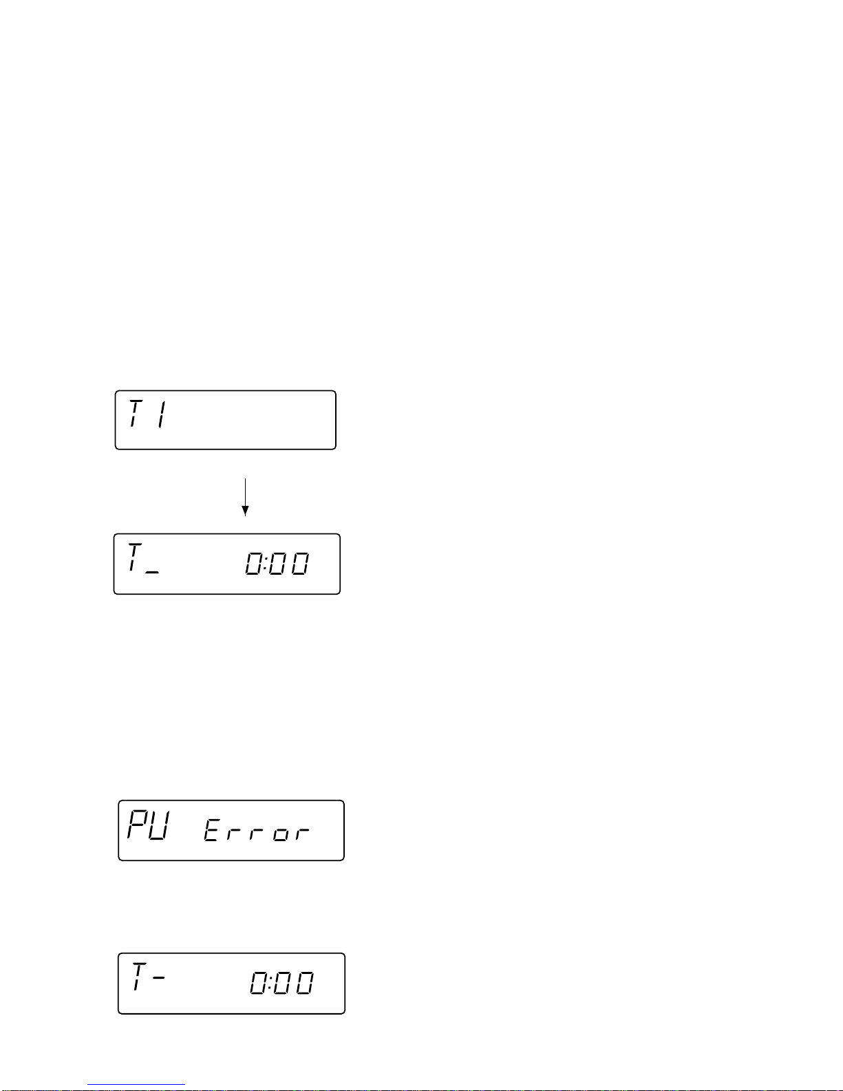
2. CD Test Mode (TEST 1)
1. Step 1 Mode
When the CD Test Mode is set, the following display lights, and the CD pickup slides to the innermost periphery.
After lighting for 1.5 sec
When the following operation key is pressed in this state, the following operation is performed.
"POWER" ................The Test Mode is set to off, power is turned off, and the mode is changed to the regular standby mode.
"FF/FWD" ................After the pickup returns once to the innermost periphery, the pickup slides to the external periphery while
.................................this key is held down.
"REW/REV" .............After the pickup returns once to the innermost periphery, the pickup slides to the internal periphery while
.................................this key is held down. However, input is invalid if PU-IN is on.
"PLAY".....................Shift to Step 2
"STOP" ....................Invalid
* In case of mode entry the pickup is moved to the internal periphery. At this time entry of any key other than POWER key is
disabled until shift of pickup to the internal periphery is completed. If PU-IN SW ON cannot be detected while waiting for 10
seconds, the slide motor is stopped, the following error is displayed, and entry of any key other than POWER key is disabled.
XL-520W/CP-520
– 12 –
When the following operation key is pressed in this state, the following operation is performed.
"POWER" ................The Test Mode is set to off, power is turned off, and the mode is changed to the regular standby mode.
"FF/FWD" ................While this key is held down, the pickup slides to the external periphery.
"REW/REV" .............While this key is held down, the pickup slides to the internal periphery. However, if PU-IN is on, entry is
.................................invalid.
"PLAY".....................Shift to Step 3
"STOP" ....................Return to Step 1
3. Step 3 Mode
While the laser is lighting, the focus servo is turned on, and focus search is performed. If focusing failure occurs, focus search
is repeated until focusing is attained.
When the following operation keys are pressed in this state, the following operations are performed.
"POWER" ................The Test Mode is set to off, power is turned off, and the mode is changed to the regular standby mode.
"FF/FWD" ................While this key is held down, the pickup slides to the external periphery.
"REW/REV" .............While this key is held down, the pickup slides to the internal periphery. However, if PU-IN is on, entry is
.................................invalid.
"PLAY".....................If focusing has been attained, the process proceeds to Step 4. Unless focusing has been attained,
.................................reception is inhibited.
"STOP" ....................Return to Step 1
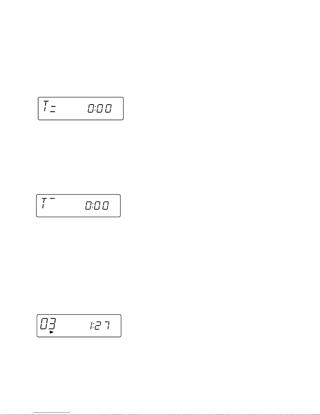
4. Step 4 Mode
The disc is rotated and CLV is locked while the tracking servo is off.
The time display indicates always "0:00".
When the following operation keys are pressed in this state, thefollowing operations are performed.
"POWER" ................The Test Mode is set to off, power is turned off, and the mode is changed to the regular standby mode.
"FF/FWD" ................While this key is held down, the pickup slides to the external periphery.
"REW/REV" .............While this key is pressed, the pickup slides to the internal periphery. However, if PU-IN is on, entry is
.................................invalid.
"PLAY".....................Shift to Step 5
"STOP" ....................Return to Step 1
5. Step 5 Mode
The tracking servo is turned on, groove is traced, mute is set to off, and playback is started. Even when the outermost
periphery of disc is reached in playback mode, it does not stop. The LCD display indicates playback lapse time as in case
of regular CD playback.

– 13 –
XL-520W/CP-520
When the following operation keys are pressed in this state, the following operations are performed.
"POWER" ................The Test Mode is set to off, power is turned off, and the mode is changed to the regular standby mode.
"FF/FWD" ................While this key is held down, the pickup slides to the external periphery.
"REW/REV" .............While this key is held down, the pickup slides to the internal periphery. However, if PU-IN is on, entry is
.................................invalid.
"PLAY".....................Invalid
"STOP" ....................Return to Step 1
Other cautions
• While the CD lid OPEN is detected, entry into any step later than Step 2 is disabled. If CD lid OPEN is detected in any step
higher than Step 2, return to Step 1 is done.
• TOC IL is not performed in the Test Mode.
• The key operation, excepting that specified above, is the same as that of regular operation (CD). Only the FUNCTION key
is input-inhibited.
• Syncro REC with REC key input is also invalid in this mode.
3. Tuner Test Mode (TEST 3)
1. Outline of tuner (radio) Test Mode
The tuner Test Mode is intended to store adjustment/measurement frequency in the preset memory CH without frequency
adjustment by the adjusting personnel when the tuner is adjusted in the production line.
2. Details of tuner Test Mode
When power is turned on with the POWER key while the MEMORY/SET key and BAND key are held down together in
POWER OFF state, the frequency for adjustment/measurement of specific destination specified by the AREA terminal is
preset-stored in the preset memory CH (the frequency to be preset-stored for specific destination is explained in the Item
C). When the tuner Test Mode is started up, it is started with FM. FM is FM STEREO only.
When the REW key is pressed while the preset memory CH is 1CH, the highest CH is found as in case of regular mode. When
the FF key is pressed while the preset memory CH is highest CH, 1CH is found.
The RADIO (TUNER) BAND key (or TUNER/BAND key on the remote controller) is valid.
As in case of regular mode, selection of band, FM MONO/STEREO mode is enabled by pressing the RADIO (TUNER) BAND
(or TUNER/BAND ) key.
Exiting the tuner Test Mode, When the destruction data is stored in the memory in the tuner Test Mode, AC supply is
interrupted in the Test Mode and the AC supply is recovered, all the memory is cleared with the destruction data in case of
start-up.
(Countermeasures so that the Test Mode memory does not remain when AC supply is restored after power supply failure
occurred once in the Test Mode.) The memory is not cleared when AC supply is turned off after POWER OFF.
FUNCTIONkey is not accepted in the tuner test mode. In case of exit from the tuner Test Mode through the backup mode
upon occurrence of power failure the frequency data stored in the preset memory for adjustment/measurement is erased.
(As a result the preset memory CH becomes empty.)
The display indication is the same as that in case of regular operation.
The following display lights for one second when the tuner TEST mode is turned on
XL-520W/CP-520
– 14 –
Test Mode operation specification
3. Preset frequencies for various destinations (random preset memory)
BAND (CH)
1 FM 87.5MHz
2 FM 108.0MHz
3 FM 98.0MHz
4 FM 90.0MHz
5 FM 106.0MHz
• The unit used in the table above is Hz. K represents 1,000 times, and M represents 1,000,000 times.
• The hatched data shown in the table are not stored in the memory.
• FM is stereo mode.
Note: Keys which are effective in Test Mode
• Main unit keys: VOLUME UP/DOWN, BAND, TUNING UP, POWER, MEMORY, CLEAR,
PRESET UP/DOWN
• Remote controller keys:
VOL UP/DOWN, BAND, TUNING UP/DOWN, POWER, MEMORY, CLEAR, PRESET UP/DOWN
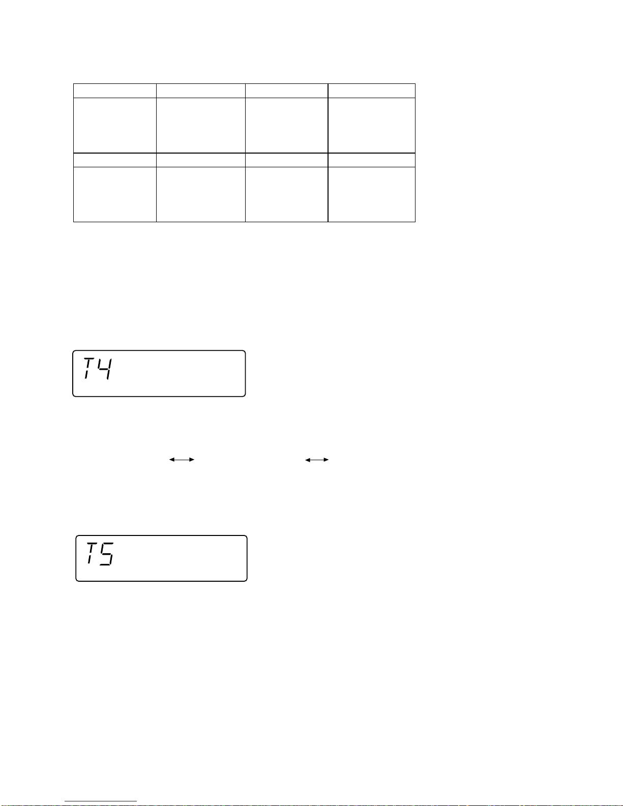
4. Electronic volume Test Mode (TEST 4)
After the Test Mode is set, the following display lights for one second.
1 FM 87.5MHz
2 FM 108.0MHz
3 FM 98.0MHz
4 FM 90.0MHz
5 FM 106.0MHz
When this mode has been set, -14dB (STEP17) is set, the preset equalizer is set to FLAT (EQ-3), the SRS mode is set to OFF,
and the start-up function is set to Tape.
1. The display is the same as that indicated in case of regular operation excepting when Test Mode is set.
2. The volume control with the Volume UP/DOWN key is only the following 3 steps, differing from the volume control in the regular
operation mode.
Volume — ∞ (STEP 0) Volume — 14dB (STEP 17) Volume — 0 (STEP 24)
3. The preset equalizer and SRS are switched if key operation is performed.
5. Timer Test Mode (TEST 5)
When the Test Mode is set, the following display lights for one second.
The current time and timer time are set in the following procedure, and timer playback is performed.
1. The present time is set to 1:00, the timer is set to ON time 1:02, OFF time 1:12, Function is set to Tape, Volume is set to STEP8.
One minute is counted in increments of second, and timer playback is performed. One step of Fade-in/out in this mode is
performed for 0.5 sec.
The display is the same as that appears in the regular timer operation.
2. After completion of timer playback test "TEST-5" indication (which appears when the mode is set) appears again and Standby
state is set. PLAY key entry is waited. If an entry is detected, the SLEEP timer is set to 2 minutes, and Function is set to
Tape, so that playback is started at once. Volume is set to STEP8, and 10 seconds are counted down in decrements of
second. One step of Fade-out is 0.5 sec.
The display is the same as that appears in the regular sleep playback mode.
3. After completion of SLEEP test, the Test Mode is turned off, and regular standby mode is set, so that the Test Mode ends.
6. LCD Test Mode (TEST 6)
When the LCD Test Mode is set, all the LCD segments light.
BAND (CH)
10 kHz SPAN
100 kHz SPAN
BAND (CH)
6 AM 531 kHz
7 AM 1,602 kHz
8 AM 990 kHz
9 AM 603 kHz
10 AM 1,404 kHz
6 AM 530 kHz
7 AM 1,620 kHz
8 AM 990 kHz
9 AM 600 kHz
10 AM 1,400 kHz
BAND (CH)
9 kHz SPAN
10 kHz SPAN

– 15 –
XL-520W/CP-520
In this Test Mode checking as to whether all the main unit keys can be detected is performed. Accordingly, when this mode
is set, checking is performed so as to examine whether the POWER key was pressed last after all the following keys were
pressed. If the result is OK, the following OK is displayed. If any one of keys was not pressed, an error is indicated. When the
POWER key is pressed, exit from the mode is made irrespective of whether the termination is normal or abnormal, and the
standby mode is set.
All the models using this microcomputer do not have the same keys. The entry of the following keys is detected depending on
the combination of simultaneously pressed keys when this mode is set. Key pressing order is not fixed. Pressing of all keys
must be detected.
1. In case of "SRS" + "REC PAUSE"
Since the model does not have RDS and SRS, all the keys to be detected are the following 12 keys.
PLAY, VOL , VOL , BAND, G-EQ, FUNCTION, MEMORY/SET, REC PAUSE, REW/REV, FF/FWD, STOP, SRS
OK/NG indication of test result must be as follows.
<
<
NG indication
OK indication
7. Key input diagnosis Test Mode (TEST A)
When the Test Mode is set, the following display appears.
XL-520W/CP-520
– 16 –
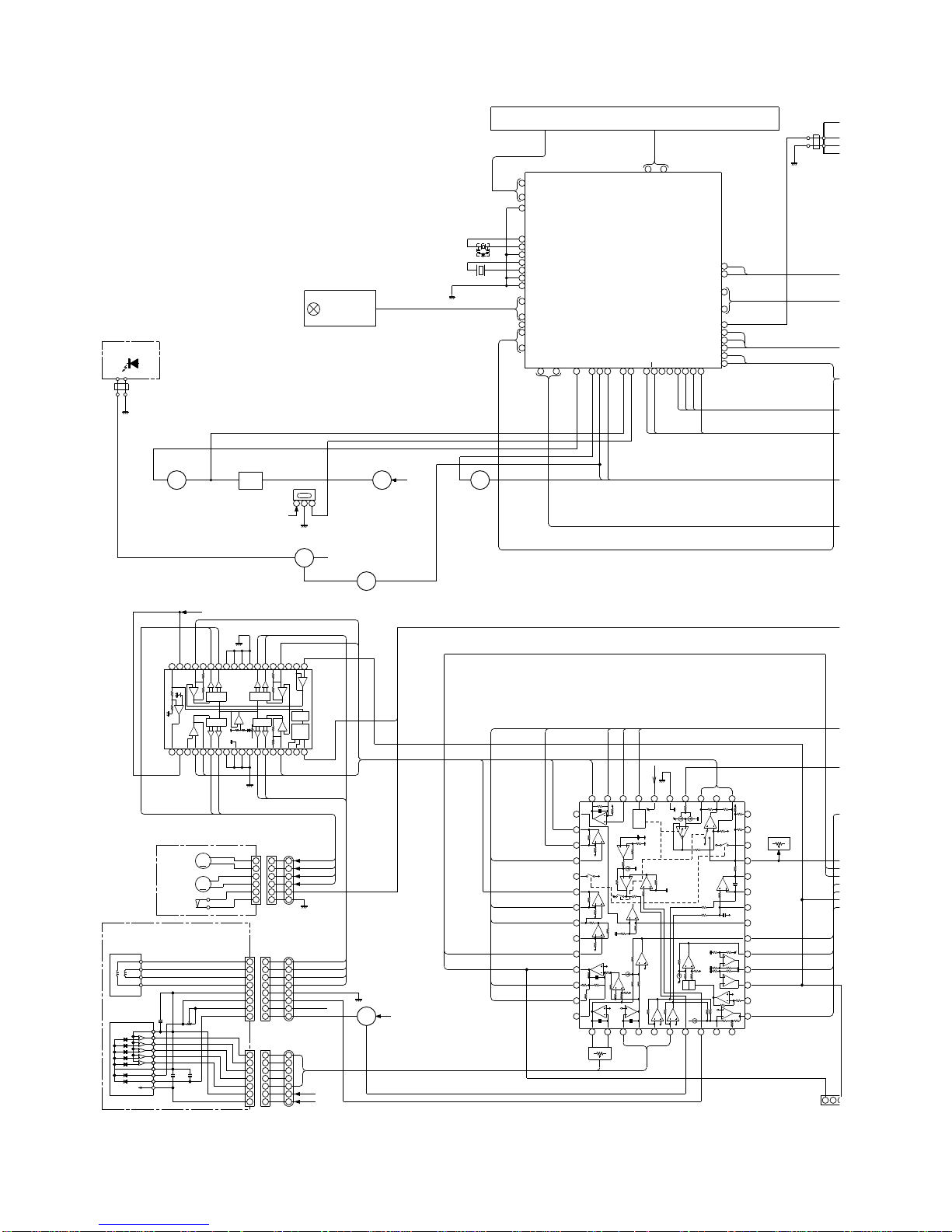
Figure 16 BLOCK DIAGRAM (1/4)
1
4
9
10
11
12
13
14
15
17
19
21
23
25 31 32 34 35 36 38 39 41 42 45 4640 44 47 48
51
52
53
54
55
56
63
64
57
62
5
321
987654321
18 17 16 15 14 13 12 11 10
28 29 30 31 32 33 34 35 36
19 20 21 22 23 24 25 26 27
8
7
6
5
4
3
2
1
88
77
66
55
44
33
22
11
7
6
5
4
3
2
1
77
66
55
44
33
22
11
6
5
4
3
2
1
6
5
4
3
2
1
6
5
4
3
2
1
9
10
11
12
13
14
15161718192021222324
25
26
27
28
29
30
31
32
33
34
35
36
37
38
39 40 41 42 43 44 45 46 47 48
8
7
6
5
4
3
2
1
32
1
FSO
M+12V
µ-CON +5V
~
~
~
~
~
~
IX0189AW
IC701
~
PU-IN
BUS3
SRS1
SRS2
~
~
~
~
~
7493
SEG26
SEG7
COM0
COM3
DI
CE
LCD
LCD701
LID-SW
BIAS
B-CAN
REC
MOT
SOL
FW701
LED704 - LED712
SW710-SW714
SW718
SW702-SW708
KEY
RX701
RESET
Q701
SWITCHING
Q702
Q703
SWTCHING
A 12V
LED+B
P CONT
SWITCHING
SWITCHING
Q707
Q706
(S+6.2VLINE)
SL–
SL+
TR+
TR–
TS2O
IC804
CD STB
DMEO
SP+
SP–
FO+
FO–
GAIN4
LEVEL
SHIFT
LEVEL
SHIFT
LEVEL
SHIFT
LEVEL
SHIFT
VCC
++
––
––
++
––
++
––
++
STAND
-BY
T.S.D
GND
Reg5V
VCC
GND
GAIN1
NC
NC
+
–
+
–
–
+
–
+
+–
–
+
–
+
ACTUATOR
TR–
FO–
FO+
TR+
C4A
C2A C3A
VR1A
VCC
LD
MON
GND
E
A
B
F
C
1/2VCC
BI801
CNS801
TR–
GND
FO–
FO+
TR+
BI802
CNS802
1/2VCC
+5V
C
F
B
A
E
1/2V
+5V
+
–
+
–
M
M
M801
SLED
M802
SPINDLE
SW801
PU-IN
BI803
CNP803
CNS803
GND
PU-IN
SL–
SL+
SP–
SP+
Q801
SWTCHING
+5V
IC801
BLANCE
VR802
ERROR
TRACKING
FOCUS
OFFSET
VR803
TEST POI
FW702
CD+5V
FMSO
Q704 Q705
PD
VR
LD
VRO
TSO
SD
R-MUTE
TPO
REMOCON
RESET
REMOCON
SYS STOP
TR–
TR+
FO+
FO–
GND
PD
VR
LD
GND
PU-IN
SL–
SL+
SP–
SP+
X702
32.768kHz
DFCT
FMSO
FMSM
FMSP
THLD
TS2O
TS2N
TS2P
TS1N
TS1P
TSO
TEL1
TEL2
TSN
RFT
RFN
TPI
TNI
TNO
FNI
FPI
LDO
MDI
GND
VCC
SEL
DMEO
DMEN
DMEP
OSCI
COSC
FSO
FSN
FHLD
FEL1
FEL2
FEI
FEN
SBAD
FEO
FEP
DFIN
RFRP
2VRO
VRO
RFI
RFO
F.P
20
VSM
BUCK
CEE
CD RES
DATA
CLE
STEREO
SYS STOP
CD+B
P-CONT
P-MUTE
RESET
CAM SW
POWER
KEY1
VREF
MMOD
XO
XI
VSS
OSC1
OSC2
VLC3
X701
8MHz
PD
LDO
– 17 –
XL-520W/CP-520
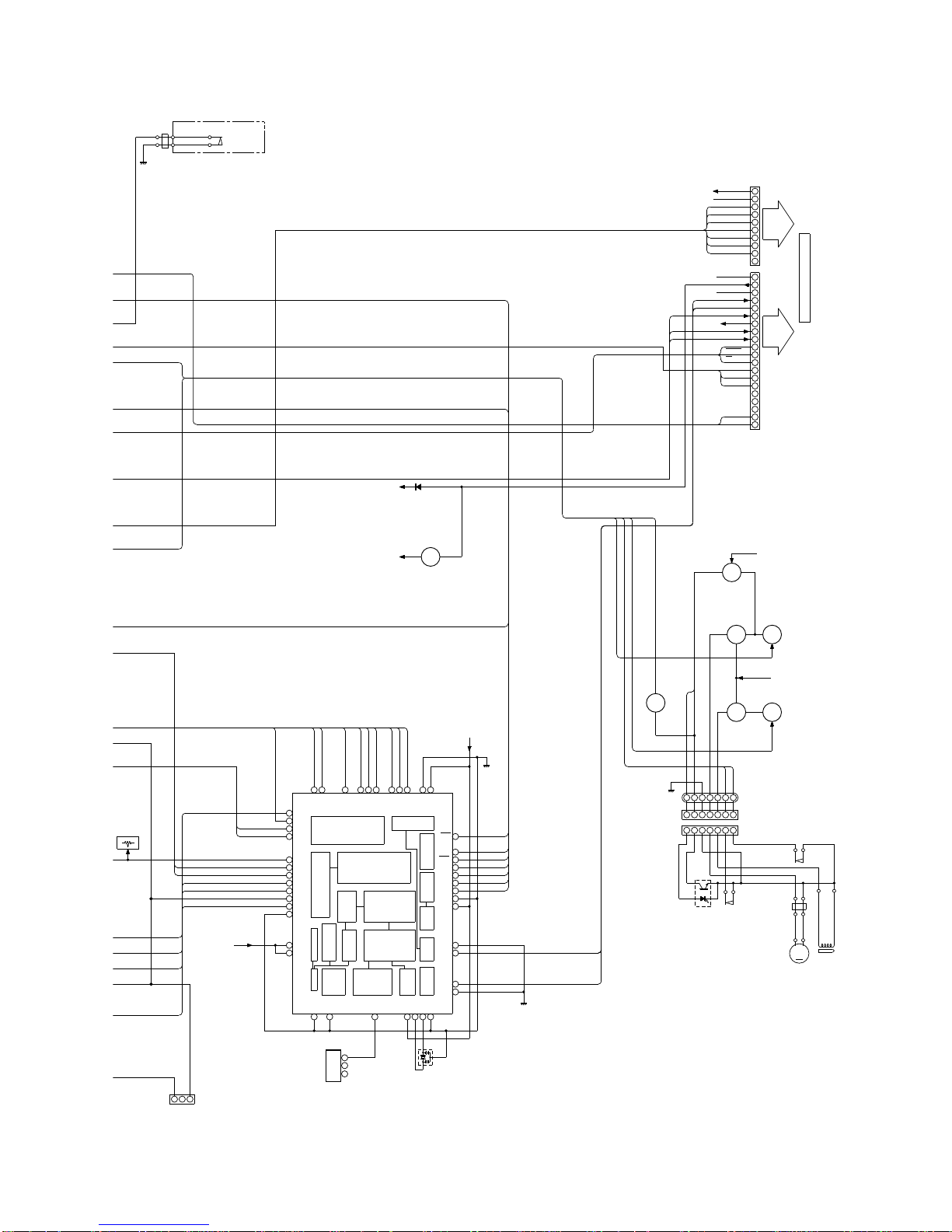
Figure 17 BLOCK DIAGRAM (2/4)
321
7
12
13
14
15
16
17
18
19
21
2526272830323334363740
41
42
43
44
47
48
49
50
51
52
53
54
58
59
65 67 7775 78 79 80
6
2
1
3
2
1
9
8
7
6
5
4
3
2
1
14
13
12
11
10
9
20
10
19
18
17
16
15
8
7
6
5
4
3
2
1
7654321
7654321
7654321
FOCUS
OFFSET
VR803
TEST POINT
TP801
DIGITAL
X801
J801
DIGITAL
OUT TO
MD/DAT
PDCNT
VDDA
GNDA
RFI
RFRP
VREF
SBAD
TEOF
TESH
FEI
FKIC
FCSI
SEL
2VREF
CCE
RST
BUCK
BUS3
BUS2
BUS1
BUS0
GNDD
VDDD
GNDA
RO
LO
GNDA
GNDX
XO
XI
VDDX
TESTX
GNDD
DA CONV
OUT
PLL
STATUS
AUDIO OUT
CLV SERVO
TMAX DET
STATUS
CODE
SUB
CLOCK
EFM
CORRECT
RAM
Q DATA
INTERFACE
CD BUS
16K RAM
ADRESS
A/D CONVERTOR
SERVO
STATUS
GENERATOR
TIMING
FOCUS
TRACKING
SERVO
CONTROL
CD+5V
FMFB
TGUH1
DMPC
DMFC
FMON
TKIC
TGUL
TEL1
TEL2
GNDD
VDDD
D-GND
CD+5V
FW702
SW701
CD EJECT
5V
(S+6.2V)
REGULATOR
Q861
TO MAIN PWB
CNS603
M 12V
D GND
VDI
DI
CE
CL
DO
VCE
VCL
CNS602
REC
R-MUTE
P CONT
P MUTE
S+6.2V
A GND
M GND
A 12V
SD
BIAS
B-CAN
FM ST
CD+B
L-CH
R-CH
SWTCHING
µ-CON5V
Q906
TAPE MOTOR
DRIVER
SWTCHING
Q905
M-12V
Q902
SWTCHING
SWTCHING
SOLENOID
DRIVER
CNP901
CNS901
BI901
SW902
CAM
PREVENTION
RECORD
SW901
PH901
FW901
–
+
SOLENOID
M
M901
TAPE
BUS0
BUS1
BUS2
BUS3
BUCK
CCE
RESET
G-GND
A-GND
CD R-CH
CD L-CH
Q904
P.F
CAM SW
Q901
Q903
VRO
TSO
SOL901
MOT
SOL
RUN PLS
IC802
PU IN
D
1
2
D
P
O
SRS1
SRS2
 Loading...