

Guide to Effective Presentations
Electronic presentations are one of the most effective
tools presenters can use to persuade an audience.
There are several ways to enhance your presentation
and maximise your effectiveness. The following are
guidelines to help you create and deliver a dynamic
presentation.
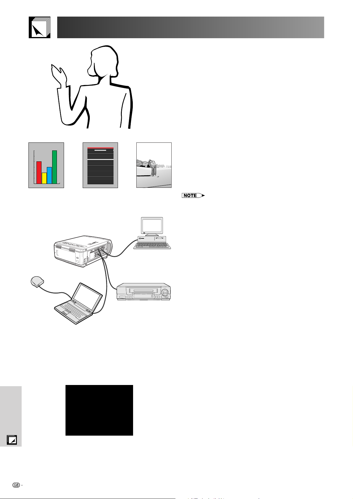
a. Types of Presentations
Computer Presentations
30
25
20
15
10
5
0
• To present basic information such as graphs, spreadsheets,
documents and images, use word processing and spreadsheet
applications.
• To convey more complex information and create more dynamic
presentations which allow you to control the pace of your delivery,
utilise software such as Astound®, Freelance®, Persuasion® or
PowerPoint®.
• For high-end multimedia and interactive presentations, use software
such as Macromedia Director®.
• Astound®, Freelance®, Persuasion®, PowerPoint® and Macromedia
Director® are trademarks of their respective companies.
Appendix
Yellow
on Black
Video Presentations
Use of video equipment, such as a VCR, DVD player and laser disc
player, can be effective for delivering instructional or illustrative
information that is difficult to present.
Digital Cameras and Personal Digital Assistants
(PDAs)
For highly compact and portable presentations, digital still cameras,
digital video cameras, document cameras and PDAs are ideal for
transferring data without cumbersome conversions.
Multimedia Presentations
You can integrate all of the above methods for a full multimedia
presentation including video, audio, computer applications and World
Wide Web information.
b. Creative Presentations
Oftentimes presenters do not take advantage of the many
subtle ways they can manipulate their electronic slides to more
effectively persuade the audience.
Colour has a great effect on the audience during a
presentation. When used correctly and legibly, studies show
that background and foreground colours establish an
emotional tone for a presentation, help viewers understand
and retain information, and influence an audience to take a
desired course of action.
Colour Considerations
• Choose legible colours.
• Text and graphics colours need sufficient contrast.
• Use darker colours for the background since a lighter background
can create uncomfortable glare. (Yellow on black creates an ideal
contrast.)
75
Guide to Effective Presentations
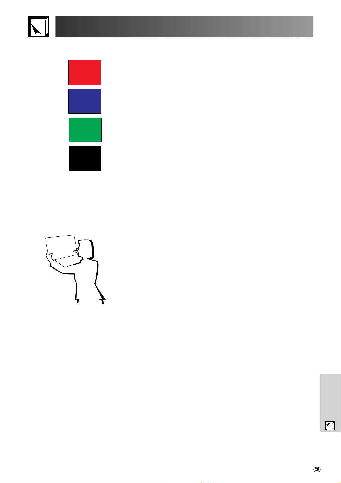
• Background colours can subconsciously affect the
audience:
Presentation from SHARP
y
n
a
in
s
e
k
ta
is
m
n
o
m
p
m
o
f ty
t c
o
s
n
o
io
t
m
c
e
h
le
e
f t
s
o
e
e
n
th
O
l is
a
a
u
re
is
to
v
n
rd
a
tio
r h
ta
n
, o
e
s
in
re
th
p
o
ll, to
a
m
s
o
to
re
t a
a
th
Red
Red—increases viewers’ pulse and breathing and
encourages risk taking but can also be associated with
financial loss.
Blue
Blue—has a calming and conservative affect on the
audience but can also create boredom among corporate
audiences that are often inundated with this background
colour.
Green
Black
Green—stimulates interaction.
Black—conveys finality and certainty. Use it as a transitional
colour between slides when moving from one idea to
another.
• Foreground colours create a major impact on how well an
audience understands and remembers a message.
• Use one or two bright colours for emphasis.
• Highlight important messages.
• The eye has a difficult time reading certain coloured text on
certain coloured backgrounds. For example, text and
background colours in red and green, and blue and black
make for difficult viewing.
• Colourblind individuals may find it difficult to distinguish
between red and green, brown and green, and purple and
f
o
e
p
ty
ts
n
fo
e
.
d
blue. Avoid using these colours together.
Fonts
• One of the most common mistakes in any type of
presentation visual is the selection of type fonts that are too
small, too thin, or too difficult to read.
Sans-serif
Serif
• If you are not sure how well a given font will read on a screen
at various sizes, try this: Draw a 15 cm 20 cm box on a
piece of paper and print out several lines of text inside the
box with your computer printer at 300 or 600 dpi resolution.
Vary the sizes of text to simulate headline, body and text
call-outs for any charts or graphs. Hold the printout at arm’s
length. This is how your text will look on a 1.2 meter-wide
screen at 3 meters, on a 2.3 meter-wide screen at 6.1 meters
and a 3.7 meter-wide screen at 9.1 meters. If you cannot
read the text easily, you should put less copy on your visuals
or use larger typefaces.
• Design your visuals so that they are visible by the viewer in
the last row.
• Nothing will ruin your presentation faster than misspelled
words. Take the time to proofread and edit your work before
your visuals become a permanent part of your presentation.
• Mixed case text is easier to read than text which is displayed
in capital letters.
• Another important attribute of fonts is whether any particular
face is serif or sans-serif. Serifs are small, usually horizontal
cross strokes that are added to the end of a letter’s main
strokes. Because of their ability to coax the eye along the
line of type, fonts with serifs are generally acknowledged to
be more readable.
Appendix
76
Guide to Effective Presentations
Good Bad Good
Presentation from SHARP
30
25
20
15
10
5
0
c. Set-Up
When giving a presentation, you need to set the stage both
figuratively and literally for success. The way you set up a
presentation room will have a great impact on the audience’s
perception of you and your message. By manipulating the
placement and use of the following tools, you will improve the
impact of your presentation.
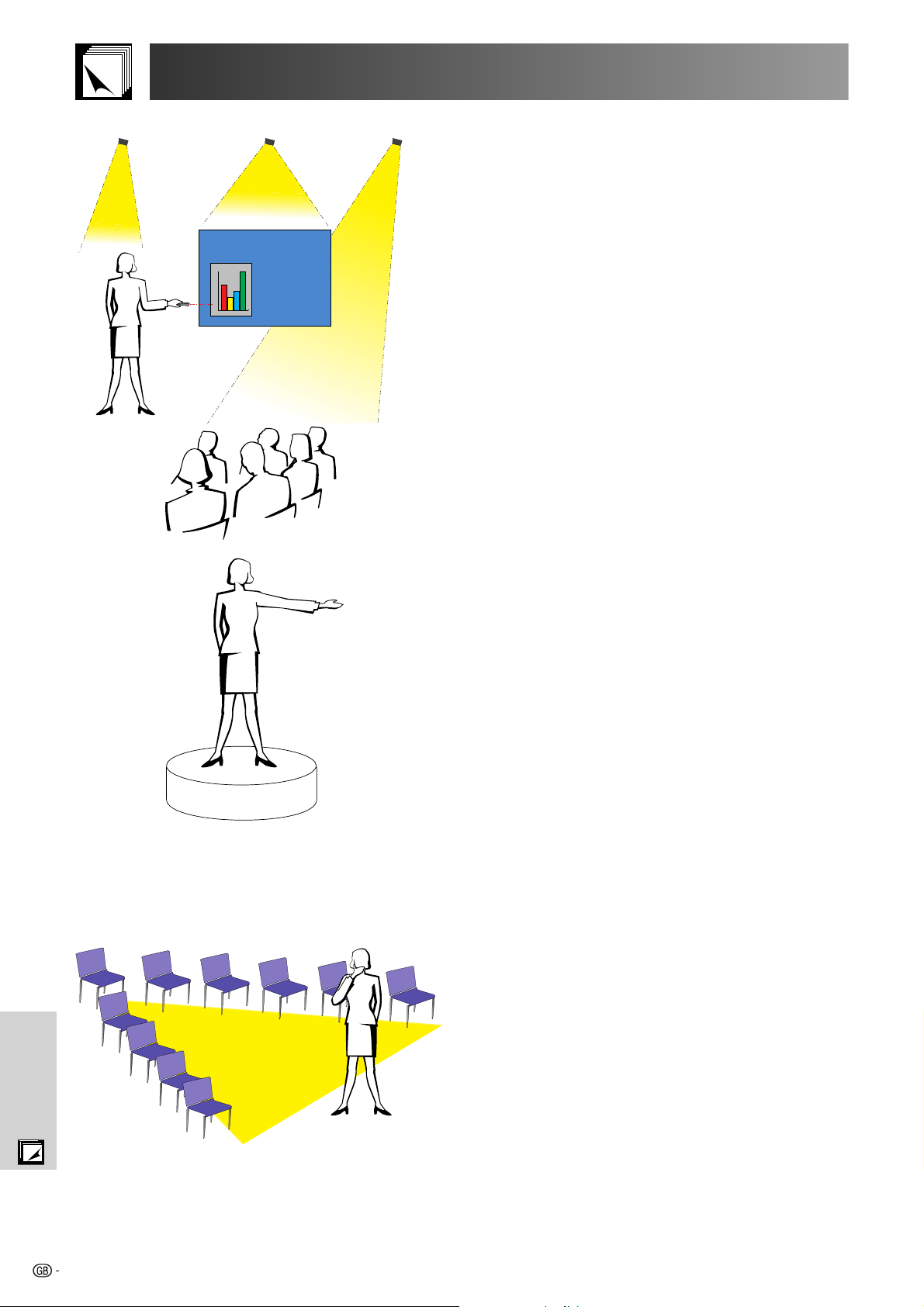
Lighting—Good lighting is an important component of a
successful presentation. You should strive to create an
unequal distribution of light. An audience should always see
as much of the presenter’s face as possible, so most of the
light should be focused on you. Because it is important for
you to be able to read the audience’s faces and body
language, some light should be shed upon them. However,
no light should shine on the screen.
Stage— When presenting on the same level surface that your
audience is on, most people can only see the top one-third of
your body. Therefore, it is recommended that when giving a
presentation to an audience of 25 or more, you stand on a
stage or platform. As more of your body is visible, the easier
it is to communicate with an audience.
Appendix
Podiums—The best presenters avoid podiums because they
hide 75% of the body and restrict movement. However, many
people feel more comfortable with a podium to hold their notes
and hide their discomfort. If you must use a podium, angle it
at 45 degrees to the audience so that you are not completely
hidden.
Visuals—It is imperative that you make sure your visuals are
large enough and projected far enough for the audience to
see. Eight times the height of an image is the optimal viewing
distance to read 24 point type. The bottom of a screen should
be at least 1.8 meters above the floor.
Screen—The screen should always be in the centre of the
room so that all audience members can see it. Because people
read from left to right, you should always stand to the
audience’s left when discussing visuals.
Seating—Arrange seating according to the dynamics of your
presentation. If the presentation is more than half-a-day, use
classroom style seating—a chair and a desk. If you would
like to encourage audience interaction, use chevron seating,
angling the chairs into a “V” shape. When you have a very
small audience, a “U” shaped arrangement will increase
interchange.
77
Guide to Effective Presentations
d. Rehearsing & Delivery
• The best time to rehearse is the day or evening before,
• Due to varying processor speeds of computers,
• Whenever possible, set up your equipment well in
• Thoroughly check every piece of equipment you bring
• Make sure you are completely familiar with the control
• If you are using a microphone, check it out before
not a couple of hours before, and the best place to
rehearse is in the actual room. Rehearsing a speech
in a small office is not the same as standing up in
front of 100 people in a hotel ballroom or classroom.
practice your slide transitions for proper timing.
advance to allow adequate time to resolve any
unexpected issues such as lighting, power, seating
and audio.
along. Make sure you have fresh batteries in your
remote controls and laptop computer. Fully charge
your computer’s battery before the presentation and
connect your AC adaptor for added safety.
panel on your projector and remote controls.
hand and walk around to see where you might have
problems with feedback. Avoid standing in these
problem areas during your presentation.
e. Presentation Tips
• Before beginning, visualise yourself delivering an
outstanding presentation.
• Know your speech, memorising at least the first three
minutes of your presentation will allow you to focus
on your rhythm and pacing.
• Speak to early arrivals to help you build a rapport
with the audience and make you feel more
comfortable.
• Do not be overly dependent on your visuals by reciting
what your audience is already reading. Know your
material well enough to be able to deliver the
presentation with ease. Use your visuals to emphasise
keypoints.
• Be sure to project your voice clearly and use eye
contact to maintain audience attention.
• Do not wait until halfway through your presentation to
get your point across. If you wait and try to create a
“build-up”, you may lose some of your audience along
the way.
• Keep your audience’s attention. As most people only
focus for 15 to 20 minutes during a one-hour
presentation, it is important to recapture their attention
periodically. Use phrases like, “This is critical to my
point” or “This is absolutely fundamental” to remind
them you are saying something they need to hear.
Appendix
78
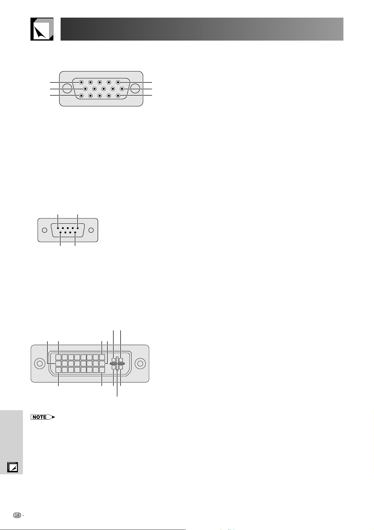
Connecting Pin Assignments
INPUT 1 RGB and OUTPUT (INPUT 1, 2) Signal Input Ports: 15-pin Mini D-sub female connector
RGB Input
Analog
1. Video input (red)
2. Video input
(green/sync on green)
3. Video input (blue)
4. Reserve input 1
10
15
5
1
6
11
5. Composite sync
6. Earth (red)
7. Earth (green/sync on green)
Component Input
Analog
R (CR)
1. P
2. Y
B (CB)
3. P
4. Not connected
5. Not connected
6. Earth (P
R)
7. Earth (Y)
8. Earth (P
B)
RS-232C Port: 9-pin D-sub male connector of the DIN-D-sub RS-232C cable
15
69
Pin No. Signal Name I/O Reference
1 CD Not connected
2 RD Receive Data Input Connected to internal circuit
3 SD Send Data Output Connected to internal circuit
4 ER Not connected
5 SG Signal Ground Connected to internal circuit
6 DR Data Set Ready Output Not connected
7 RS Request to Send Output Connected to internal circuit
8 CS Clear to Send Input Connected to internal circuit
9 CI Not connected
8. Earth (blue)
9. Not connected
10. GND
11. GND
12. Bi-directional data
13. Horizontal sync signal
14. Vertical sync signal
15. Data clock
9. Not connected
10. Not connected
11. Not connected
12. Not connected
13. Not connected
14. Not connected
15. Not connected
DVI Port: 29-pin
91 816
• *1 Return for 5 V, Hsync. and Vsync.
• *2 Analog R, G and B return
• *3 These pins are not used on this equipment.
Appendix
C1C2
C32417 C4
C5
Pin No. Name
1 T.M.D.S. Data 2
2 T.M.D.S. Data 2
3 T.M.D.S. Data 2/4 Shield
4 T.M.D.S. Data 4*
5 T.M.D.S. Data 4*
3
3
6 DDC Clock
7 DDC Data
8 Analog Vertical Sync
9 T.M.D.S. Data 1
10 T.M.D.S. Data 1
11 T.M.D.S. Data 1/3 Shield
12 T.M.D.S. Data 3*
13 T.M.D.S. Data 3*
14 5 V Power
15 Ground*
1
3
3
16 Hot Plug Detect
17 T.M.D.S. Data 0
18 T.M.D.S. Data 0
19 T.M.D.S. Data 0/5 Shield
20 T.M.D.S. Data 5*
21 T.M.D.S. Data 5*
3
3
22 T.M.D.S. Clock Shield
23 T.M.D.S. Clock
24 T.M.D.S. Clock
C1 Analog Red
C2 Analog Green
C3 Analog Blue
C4 Analog Horizontal sync
C5 Analog Ground*
2
79

(RS-232C) Specifications and Command Settings
CONTROL CONTENTS
BLACK SCREEN OFF
INPUT 1 (RGB 1)
INPUT 2 (RGB 2)
INPUT 3 (RGB 3)
INPUT 4 (VIDEO 1)
INPUT 5 (VIDEO 2)
INPUT 6 (VIDEO 3)
INPUT CHECK
FREEZE ON
FREEZE OFF
AUTO SYNC START
OK OR ERR
OK OR ERR
OK OR ERR
OK OR ERR
OK OR ERR
OK OR ERR
OK OR ERR
OK OR ERR
OK OR ERR
OK OR ERR
OK OR ERR
I
I
I
I
I
I
I
I
F
F
A
M
R
R
R
V
V
V
C
R
R
D
B
G
G
G
E
E
E
H
E
E
J
K
B
B
B
D
D
D
K
Z
Z
S
_
_
_
_
_
_
_
_
_
_
_
_
_
_
_
_
_
_
_
_
_
_
_
_
_
_
_
_
_
_
_
_
_
0
1
2
3
1
2
3
0
1
0
1
BUTTONS & REMOTE CONTROL KEY
COMMAND
PARAMETER
RETURN
PC control
A computer can be used to control the projector by connecting an RS-232C cable (null modem, cross type, sold
separately) to the projector. (See page 16 for connection.)
Communication conditions
Set the serial port settings of the computer to match that of the table.
Signal format: Conforms to RS-232C standard.
Baud rate: 9,600 bps
Data length: 8 bits
Parity bit: NON
Stop bit: 1 bit
Flow control: None
Basic format
Commands from the computer are sent in the following order: command, parameter, and return code. After the
projector processes the command from the computer, it sends a response code to the computer.
Command format
C1 C2 C3 C4 P1 P2 P3 P4
Return code (0DH)
Command 4-digits Parameter 4-digits
Response code format
Normal response
O K
Return code (0DH)
Problem response (communication error or incorrect command)
E R R
Return code (0DH)
When more than one code is being sent, send each command only after the OK response code for the previous
command from the projector is verified.
• When using the computer control function of the projector, the projector operating status cannot be read to the computer.
Therefore, confirm the status by transmitting the display commands for each adjustment menu and checking the status with
the On-screen Display. If the projector receives a command other than a menu display command, it will execute the command without displaying the On-screen Display.
Commands
EXAMPLE
• When “BRIGHT” of INPUT 1 IMAGE ADJUSTMENT is set to 10.
ProjectorComputer
RABR 1 0_
→
←
OK
POWER ON
POWER OFF
VOLUME (0–60)
MUTE ON
MUTE OFF
LENS FOCUS (30 – 30)
LENS ZOOM (30 – 30)
LENS SHIFT (30 – 30)
KEYSTONE (127 – 127)
BUTTONS & REMOTE CONTROL KEY
DIGITAL SHIFT (96 – 96)
BLACK SCREEN ON
CONTROL CONTENTS
COMMAND
PARAMETER
P
O
W
R
_
_
_
P
O
W
R
_
_
_
V
O
L
A
_
_
*
M
U
T
E
_
_
_
M
U
T
E
_
_
_
L
N
F
O
_
*
*
L
N
Z
O
_
*
*
L
N
S
H
_
*
K
E
L
N
I
M
*
Y
S
*
*
*
D
S
_
*
*
B
K
_
_
_
OK OR ERR
1
OK OR ERR
0
OK OR ERR
*
OK OR ERR
1
OK OR ERR
0
OK OR ERR
*
OK OR ERR
*
OK OR ERR
*
OK OR ERR
*
OK OR ERR
*
OK OR ERR
1
RETURN
Appendix
80

(RS-232C) Specifications and Command Settings
CONTROL CONTENTS
INPUT 2 (RGB 2) SIGNAL TYPE : RGB
INPUT 2 (RGB 2) SIGNAL TYPE : COMPONENT
INPUT 1 (RGB 1) 2D PROGRESSIVE
INPUT 1 (RGB 1) 3D PROGRESSIVE
INPUT 1 (RGB 1) Film MODE
INPUT 2 (RGB 2) 2D PROGRESSIVE
INPUT 2 (RGB 2) 3D PROGRESSIVE
INPUT 2 (RGB 2) Film MODE
INPUT 3 (RGB 3) 2D PROGRESSIVE
INPUT 3 (RGB 3) 3D PROGRESSIVE
INPUT 3 (RGB 3) Film MODE
INPUT 4 (VIDEO 1) CONTRAST (30 – 30)
INPUT 4 (VIDEO 1) BRIGHT (30 – 30)
INPUT 4 (VIDEO 1) RED (30 – 30)
INPUT 4 (VIDEO 1) BLUE (30 – 30)
INPUT 4 (VIDEO 1) COLOR (30 – 30)
INPUT 4 (VIDEO 1) TINT (30 – 30)
INPUT 4 (VIDEO 1) SHARP (30 – 30)
INPUT 4 (VIDEO 1) CLR TEMP (3 – 3)
INPUT 4 (VIDEO 1) DISPLAY
INPUT 4 (VIDEO 1) ADJUSTMENT RESET
INPUT 5 (VIDEO 2) CONTRAST (30 – 30)
INPUT 5 (VIDEO 2) BRIGHT (30 – 30)
INPUT 5 (VIDEO 2) RED (30 – 30)
INPUT 5 (VIDEO 2) BLUE (30 – 30)
INPUT 5 (VIDEO 2) COLOR (30 – 30)
INPUT 5 (VIDEO 2) TINT (30 – 30)
INPUT 5 (VIDEO 2) SHARP (30 – 30)
INPUT 5 (VIDEO 2) CLR TEMP (3 – 3)
INPUT 5 (VIDEO 2) DISPLAY
INPUT 5 (VIDEO 2) ADJUSTMENT RESET
INPUT 6 (VIDEO 3) CONTRAST (30 – 30)
INPUT 6 (VIDEO 3) BRIGHT (30 – 30)
INPUT 6 (VIDEO 3) RED (30 – 30)
INPUT 6 (VIDEO 3) BLUE (30 – 30)
INPUT 6 (VIDEO 3) COLOR (30 – 30)
INPUT 6 (VIDEO 3) TINT (30 – 30)
INPUT 6 (VIDEO 3) SHARP (30 – 30)
INPUT 6 (VIDEO 3) CLR TEMP (3 – 3)
INPUT 6 (VIDEO 3) DISPLAY
INPUT 6 (VIDEO 3) ADJUSTMENT RESET
INPUT 4 (VIDEO 1) SIGNAL TYPE : VIDEO
INPUT 4 (VIDEO 1) SIGNAL TYPE : COMPONENT
INPUT 5 (VIDEO 2) SIGNAL TYPE : VIDEO
INPUT 5 (VIDEO 2) SIGNAL TYPE : COMPONENT
INPUT 4 (VIDEO 1) 2D PROGRESSIVE
INPUT 4 (VIDEO 1) 3D PROGRESSIVE
INPUT 4 (VIDEO 1) Film MODE
INPUT 5 (VIDEO 2) 2D PROGRESSIVE
INPUT 5 (VIDEO 2) 3D PROGRESSIVE
INPUT 5 (VIDEO 2) Film MODE
INPUT 6 (VIDEO 3) 2D PROGRESSIVE
INPUT 6 (VIDEO 3) 3D PROGRESSIVE
INPUT 6 (VIDEO 3) Film MODE
(INPUT 1–6) 2D PROGRESSIVE
(INPUT 1–6) 3D PROGRESSIVE
(INPUT 1–6) Film MODE
CLOCK (150 – 150)
PHASE (60 – 60)
H-POSITION (150 – 150)
V-POSITION (60 – 60)
RGB INPUT DISPLAY
RGB ADJUSTMENT RESET
SAVE SETTING (1 – 7)
OK OR ERR
OK OR ERR
OK OR ERR
OK OR ERR
OK OR ERR
OK OR ERR
OK OR ERR
OK OR ERR
OK OR ERR
OK OR ERR
OK OR ERR
OK OR ERR
OK OR ERR
OK OR ERR
OK OR ERR
OK OR ERR
OK OR ERR
OK OR ERR
OK OR ERR
OK OR ERR
OK OR ERR
OK OR ERR
OK OR ERR
OK OR ERR
OK OR ERR
OK OR ERR
OK OR ERR
OK OR ERR
OK OR ERR
OK OR ERR
OK OR ERR
OK OR ERR
OK OR ERR
OK OR ERR
OK OR ERR
OK OR ERR
OK OR ERR
OK OR ERR
OK OR ERR
OK OR ERR
OK OR ERR
OK OR ERR
OK OR ERR
OK OR ERR
OK OR ERR
OK OR ERR
OK OR ERR
OK OR ERR
OK OR ERR
OK OR ERR
OK OR ERR
OK OR ERR
OK OR ERR
OK OR ERR
OK OR ERR
OK OR ERR
OK OR ERR
OK OR ERR
OK OR ERR
OK OR ERR
OK OR ERR
OK OR ERR
OK OR ERR
OK OR ERR
I
I
R
R
R
R
R
R
R
R
R
V
V
V
V
V
V
V
V
V
V
V
V
V
V
V
V
V
V
V
V
V
V
V
V
V
V
V
V
V
V
I
I
I
I
V
V
V
V
V
V
V
V
V
I
I
I
I
I
I
I
I
I
M
B
B
A
A
A
B
B
B
C
C
C
A
A
A
A
A
A
A
A
A
A
B
B
B
B
B
B
B
B
B
B
C
C
C
C
C
C
C
C
C
C
A
A
B
B
A
A
A
B
B
B
C
C
C
M
M
M
N
N
A
A
A
A
E
S
S
I
I
I
I
I
I
I
I
I
P
B
R
B
C
T
S
C
R
R
P
B
R
B
C
T
S
C
R
R
P
B
R
B
C
T
S
C
R
R
S
S
S
S
I
I
I
I
I
I
I
I
I
I
I
I
C
P
H
V
R
R
M
I
I
P
P
P
P
P
P
P
P
P
I
R
D
E
O
I
H
T
E
E
I
R
D
E
O
I
H
T
E
E
I
R
D
E
O
I
H
T
E
E
V
V
V
V
P
P
P
P
P
P
P
P
P
P
P
P
L
H
P
P
E
E
S
_
_
_
_
_
_
_
_
_
_
_
_
_
_
_
_
_
_
_
_
_
*
*
*
*
*
*
_
_
_
_
*
*
*
*
*
*
_
_
_
_
_
_
_
_
_
_
_
_
_
_
_
_
_
_
_
_
*
_
*
_
_
_
_
_
_
_
_
_
_
_
_
_
_
_
*
*
*
*
*
*
*
_
_
_
*
*
*
*
*
*
*
_
_
_
*
*
*
*
*
*
*
_
_
_
_
_
_
_
_
_
_
_
_
_
_
_
_
_
_
_
*
*
*
*
_
_
_
_
_
_
_
_
_
_
_
_
_
_
*
*
*
*
*
*
*
*
_
_
*
*
*
*
*
*
*
*
_
_
*
*
*
*
*
*
*
*
_
_
_
_
_
_
_
_
_
_
_
_
_
_
_
_
_
_
*
*
*
*
_
_
_
0
1
0
1
2
0
1
2
0
1
2
*
*
*
*
*
*
*
*
0
1
*
*
*
*
*
*
*
*
0
1
*
*
*
*
*
*
*
*
0
1
0
1
0
1
0
1
2
0
1
2
0
1
2
0
1
2
*
*
*
*
0
1
*
PICTUREFINE SYNC
*1
COMMAND
PARAMETER
RETURN
CONTROL CONTENTS
INPUT 1 (RGB 1) RESIZE : NORMAL
INPUT 1 (RGB 1) RESIZE : FULL
INPUT 1 (RGB 1) RESIZE : DOT BY DOT
INPUT 2 (RGB 2) RESIZE : NORMAL
INPUT 2 (RGB 2) RESIZE : FULL
INPUT 2 (RGB 2) RESIZE : DOT BY DOT
INPUT 3 (RGB 3) RESIZE : NORMAL
Appendix
INPUT 3 (RGB 3) RESIZE : FULL
INPUT 3 (RGB 3) RESIZE : DOT BY DOT
INPUT 4 (VIDEO 1) RESIZE : NORMAL
INPUT 4 (VIDEO 1) RESIZE : FULL
INPUT 4 (VIDEO 1) RESIZE : BORDER
INPUT 4 (VIDEO 1) RESIZE : STRETCH
INPUT 4 (VIDEO 1) RESIZE : SMART STRETCH
INPUT 5 (VIDEO 2) RESIZE : NORMAL
INPUT 5 (VIDEO 2) RESIZE : FULL
INPUT 5 (VIDEO 2) RESIZE : BORDER
INPUT 5 (VIDEO 2) RESIZE : STRETCH
INPUT 5 (VIDEO 2) RESIZE : SMART STRETCH
INPUT 6 (VIDEO 3) RESIZE : NORMAL
BUTTONS & REMOTE CONTROL KEYPICTURE
INPUT 6 (VIDEO 3) RESIZE : FULL
INPUT 6 (VIDEO 3) RESIZE : BORDER
INPUT 6 (VIDEO 3) RESIZE : STRETCH
INPUT 6 (VIDEO 3) RESIZE : SMART STRETCH
RGB GAMMA : STANDARD
RGB GAMMA : GAMMA1
RGB GAMMA : GAMMA2
RGB GAMMA : CUSTOM
VIDEO GAMMA : STANDARD
VIDEO GAMMA : GAMMA1
VIDEO GAMMA : GAMMA2
VIDEO GAMMA : CUSTOM
INPUT 1 (RGB 1) CONTRAST (30 – 30)
INPUT 1 (RGB 1) BRIGHT (30 – 30)
INPUT 1 (RGB 1) RED (30 – 30)
INPUT 1 (RGB 1) BLUE (30 – 30)
INPUT 1 (RGB 1) COLOR (30 – 30)
INPUT 1 (RGB 1) TINT (30 – 30)
INPUT 1 (RGB 1) SHARP (30 – 30)
INPUT 1 (RGB 1) CLR TEMP (3 – 3)
INPUT 1 (RGB 1) DISPLAY
INPUT 1 (RGB 1) ADJUSTMENT RESET
INPUT 2 (RGB 2) CONTRAST (30 – 30)
INPUT 2 (RGB 2) BRIGHT (30 – 30)
INPUT 2 (RGB 2) RED (30 – 30)
INPUT 2 (RGB 2) BLUE (30 – 30)
INPUT 2 (RGB 2) COLOR (30 – 30)
INPUT 2 (RGB 2) TINT (30 – 30)
INPUT 2 (RGB 2) SHARP (30 – 30)
INPUT 2 (RGB 2) CLR TEMP (3 – 3)
INPUT 2 (RGB 2) DISPLAY
INPUT 2 (RGB 2) ADJUSTMENT RESET
INPUT 3 (RGB 3) CONTRAST (30 – 30)
INPUT 3 (RGB 3) BRIGHT (30 – 30)
INPUT 3 (RGB 3) RED (30 – 30)
INPUT 3 (RGB 3) BLUE (30 – 30)
INPUT 3 (RGB 3) COLOR (30 – 30)
INPUT 3 (RGB 3) TINT (30 – 30)
INPUT 3 (RGB 3) SHARP (30 – 30)
INPUT 3 (RGB 3) CLR TEMP (3 – 3)
INPUT 3 (RGB 3) DISPLAY
INPUT 3 (RGB 3) ADJUSTMENT RESET
INPUT 1 (RGB 1) SIGNAL TYPE : RGB
INPUT 1 (RGB 1) SIGNAL TYPE : COMPONENT
81
COMMAND
PARAMETER
R
A
S
R
_
_
_
R
A
S
R
_
_
_
R
A
S
R
_
_
_
R
B
S
R
_
_
_
R
B
S
R
_
_
_
R
B
S
R
_
_
_
R
C
S
R
_
_
_
R
C
S
R
_
_
R
C
R
A
R
A
R
A
R
A
R
A
R
B
R
B
R
B
R
B
R
B
R
C
R
C
R
C
R
C
R
C
G
A
G
A
G
A
G
A
G
A
G
A
G
A
G
A
R
A
R
A
R
A
R
A
R
A
R
A
R
A
R
A
R
A
R
A
R
B
R
B
R
B
R
B
R
B
R
B
R
B
R
B
R
B
R
B
R
C
R
C
R
C
R
C
R
C
R
C
R
C
R
C
R
C
R
C
I
A
I
A
_
S
R
_
_
_
S
V
_
_
_
S
V
_
_
_
S
V
_
_
_
S
V
_
_
_
S
V
_
_
_
S
V
_
_
_
S
V
_
_
_
S
V
_
_
_
S
V
_
_
_
S
V
_
_
_
S
V
_
_
_
S
V
_
_
_
S
V
_
_
_
S
V
_
_
_
S
V
_
_
_
M
R
_
_
_
M
R
_
_
_
M
R
_
_
_
M
R
_
_
_
M
V
_
_
_
M
V
_
_
_
M
V
_
_
_
M
V
_
_
_
P
I
_
*
*
B
R
_
*
*
R
D
_
*
*
B
E
_
*
*
C
O
_
*
*
T
I
_
*
*
S
H
_
*
*
C
T
_
_
*
R
E
_
_
_
R
E
_
_
_
P
I
_
*
*
B
R
_
*
*
R
D
_
*
*
B
E
_
*
*
C
O
_
*
*
T
I
_
*
*
S
H
_
*
*
C
T
_
_
*
R
E
_
_
_
R
E
_
_
_
P
I
_
*
*
B
R
_
*
*
R
D
_
*
*
B
E
_
*
*
C
O
_
*
*
T
I
_
*
*
S
H
_
*
*
C
T
_
_
*
R
E
_
_
_
R
E
_
_
_
S
I
_
_
_
S
I
_
_
_
OK OR ERR
1
OK OR ERR
5
OK OR ERR
3
OK OR ERR
1
OK OR ERR
5
OK OR ERR
3
OK OR ERR
1
OK OR ERR
5
OK OR ERR
3
OK OR ERR
1
OK OR ERR
5
OK OR ERR
3
OK OR ERR
2
OK OR ERR
4
OK OR ERR
1
OK OR ERR
5
OK OR ERR
3
OK OR ERR
2
OK OR ERR
4
OK OR ERR
1
OK OR ERR
5
OK OR ERR
3
OK OR ERR
2
OK OR ERR
4
OK OR ERR
1
OK OR ERR
2
OK OR ERR
3
OK OR ERR
4
OK OR ERR
1
OK OR ERR
2
OK OR ERR
3
OK OR ERR
4
OK OR ERR
*
OK OR ERR
*
OK OR ERR
*
OK OR ERR
*
OK OR ERR
*
OK OR ERR
*
OK OR ERR
*
OK OR ERR
*
OK OR ERR
0
OK OR ERR
1
OK OR ERR
*
OK OR ERR
*
OK OR ERR
*
OK OR ERR
*
OK OR ERR
*
OK OR ERR
*
OK OR ERR
*
OK OR ERR
*
OK OR ERR
0
OK OR ERR
1
OK OR ERR
*
OK OR ERR
*
OK OR ERR
*
OK OR ERR
*
OK OR ERR
*
OK OR ERR
*
OK OR ERR
*
OK OR ERR
*
OK OR ERR
0
OK OR ERR
1
OK OR ERR
0
OK OR ERR
1
RETURN

(RS-232C) Specifications and Command Settings
CONTROL CONTENTS
LAMP QUANTITY
LAMP 1 STATUS
LAMP 2 STATUS
PRJ MODE : REVERSE OFF
PRJ MODE : REVERSE ON
PRJ MODE : INVERT OFF
PRJ MODE : INVERT ON
STACK SETTING : NORMAL
STACK SETTING : MASTER
STACK SETTING : SLAVE
KEYLOCK LEVEL : NORMAL
KEYLOCK LEVEL : LEVEL A
KEYLOCK LEVEL : LEVEL B
SET INPUTS : INPUT 1 NO USE
SET INPUTS : INPUT 1 USE
SET INPUTS : INPUT 2 NO USE
SET INPUTS : INPUT 2 USE
SET INPUTS : INPUT 3 NO USE
SET INPUTS : INPUT 3 USE
SET INPUTS : INPUT 4 NO USE
SET INPUTS : INPUT 4 USE
SET INPUTS : INPUT 5 NO USE
SET INPUTS : INPUT 5 USE
SET INPUTS : INPUT 6 NO USE
SET INPUTS : INPUT 6 USE
ID NO. CHECK
LANGUAGE SELECTION : ENGLISH
LANGUAGE SELECTION : DEUTSCH
LANGUAGE SELECTION : ESPAÑOL
LANGUAGE SELECTION : NEDERLANDS
LANGUAGE SELECTION : FRANÇAIS
LANGUAGE SELECTION : ITALIANO
LANGUAGE SELECTION : SVENSKA
LANGUAGE SELECTION :
LANGUAGE SELECTION : PORTUGUÊS
LANGUAGE SELECTION :
LANGUAGE SELECTION :
MODEL NAME CHECK
NOISE FILTER OFF
NOISE FILTER ON
*2
SERIAL NO. CHECK
*3
PROJECTOR NAME
*4
1 OR 2
0: OFF, 1: ON, 2: RETRY,
3: WAITING, 4: LAMP ERROR
OK OR ERR
OK OR ERR
OK OR ERR
OK OR ERR
OK OR ERR
OK OR ERR
OK OR ERR
OK OR ERR
OK OR ERR
OK OR ERR
OK OR ERR
OK OR ERR
OK OR ERR
OK OR ERR
OK OR ERR
OK OR ERR
OK OR ERR
OK OR ERR
OK OR ERR
OK OR ERR
OK OR ERR
OK OR ERR
001–250
OK OR ERR
OK OR ERR
OK OR ERR
OK OR ERR
OK OR ERR
OK OR ERR
OK OR ERR
OK OR ERR
OK OR ERR
OK OR ERR
OK OR ERR
MODEL NAME
OK OR ERR
OK OR ERR
SERIAL NO.
OK OR ERR
PROJECTOR NAME
T
T
T
I
I
I
I
S
S
S
K
K
K
R
R
R
R
R
R
V
V
V
V
V
V
R
M
M
M
M
M
M
M
M
M
M
M
M
N
N
S
P
P
L
L
L
M
M
M
M
T
T
T
E
E
E
A
A
B
B
C
C
A
A
B
B
C
C
D
E
E
E
E
E
E
E
E
E
E
E
N
F
F
N
J
J
P
P
P
R
R
I
I
A
A
A
Y
Y
Y
S
S
S
S
S
S
S
S
S
S
S
S
I
L
L
L
L
L
L
L
L
L
L
L
R
I
I
R
N
N
N
S
S
E
E
N
N
K
K
K
L
L
L
I
I
I
I
I
I
I
I
I
I
I
I
D
A
A
A
A
A
A
A
A
A
A
A
D
L
L
D
A
A
_
_
_
_
_
_
_
_
_
_
_
_
_
_
_
_
_
_
_
_
_
_
_
_
_
_
_
_
_
_
_
_
_
_
_
_
_
_
_
_
_
_
_
_
_
_
_
_
_
_
_
_
_
_
_
_
_
_
_
_
_
_
_
_
_
_
_
_
_
_
_
_
_
_
_
_
_
_
_
_
_
_
_
_
_
_
_
_
_
_
_
_
_
_
_
_
_
_
_
_
_
_
_
_
_
_
_
_
_
_
_
_
_
_
_
_
_
_
_
_
_
_
1
_
_
_
_
_
_
1
1
2
0
1
0
1
0
1
2
0
1
2
0
1
0
1
0
1
0
1
0
1
0
1
1
0
1
2
3
4
5
6
7
8
9
0
1
0
1
1
1
2
OPTIONS (2)LANGUAGE
COMMAND
PARAMETER
RETURN
SELECT SETTING (1 – 7)
RGB HORIZONTAL FREQUENCY CHECK
*1
RGB VERTICAL FREQUENCY CHECK
AUTO SYNC ON
AUTO SYNC OFF
FINE SYNC
AUTO SYNC DISPLAY ON
AUTO SYNC DISPLAY OFF
BALANCE (30 – 30)
TREBLE (30 – 30)
BASS (30 – 30)
AUDIOOPTIONS (1)OPTIONS (2)
AUDIO DISPLAY
AUDIO ADJUSTMENT RESET
PICT IN PICT : BOTTOM RIGHT
PICT IN PICT : BOTTOM LEFT
PICT IN PICT : UPPER RIGHT
PICT IN PICT : UPPER LEFT
PICT IN PICT RESET
VIDEO 3D DNR OFF
VIDEO 3D DNR ON
OSD DISPLAY ON
OSD DISPLAY OFF (LEVEL A)
OSD DISPLAY OFF (LEVEL B)
BLACK SCREEN DISPLAY ON
BLACK SCREEN DISPLAY OFF
VIDEO SYSTEM SELECTION : AUTO
VIDEO SYSTEM SELECTION : PAL
VIDEO SYSTEM SELECTION : SECAM
VIDEO SYSTEM SELECTION : NTSC4.43
VIDEO SYSTEM SELECTION : NTSC3.58
VIDEO SYSTEM SELECTION : PAL_M
VIDEO SYSTEM SELECTION : PAL_N
BACKGROUND SELECTION : SHARP
BACKGROUND SELECTION : CUSTOM
BACKGROUND SELECTION : BLUE
BACKGROUND SELECTION : NONE
STARTUP IMAGE SELECTION : SHARP
STARTUP IMAGE SELECTION : CUSTOM
STARTUP IMAGE SELECTION : NONE
MONITOR OUT OFF
MONITOR OUT ON
AUTO POWER OFF : NO USE
AUTO POWER OFF : USE
ID NO. LED DISPLAY : DISPLAY OFF
ID NO. LED DISPLAY : STANDBY OFF
ID NO. LED DISPLAY : DISPLAY ON
LAMP 1 USAGE TIME
LAMP 2 USAGE TIME
LAMP MODE : BOTH LAMPS
LAMP MODE : LAMP 1 ONLY
LAMP MODE : LAMP 2 ONLY
LAMP MODE : EQUAL USE
• If an underbar (_) appears in the parameter column, enter a space. If an asterisk (*) appears, enter a value in the range
indicated in brackets under CONTROL CONTENTS.
*1
FINE SYNC can only be set in the displayed RGB mode.
•
•*2Noise may appear when used with certain computers. Set the NOISE FILTER to ON using the RS-232C command.
*3
SERIAL NO. CHECK command is used to read out the 12 digits of serial No..
•
*4
After OK is returned, enter PROJECTOR NAME, up to 16-character memory. The PROJECTOR NAME in memory can then
•
be output (confirmed).
CONTROL CONTENTS
COMMAND
M
E
T
F
T
F
A
A
A
A
I
M
I
M
A
A
A
A
A
A
A
A
A
A
P
I
P
I
P
I
P
I
P
I
3
D
3
D
I
M
I
M
I
M
I
M
I
M
M
E
M
E
M
E
M
E
M
E
M
E
M
E
I
M
I
M
I
M
I
M
I
M
I
M
I
M
M
O
M
O
A
P
A
P
I
L
I
L
I
L
T
L
T
L
L
P
L
P
L
P
L
P
M
R
R
D
D
A
A
B
T
B
R
R
N
N
N
N
N
N
N
D
D
D
B
B
S
S
S
S
S
S
S
B
B
B
B
S
S
S
U
U
O
O
E
E
E
T
T
M
M
M
M
PARAMETER
L
_
Q
_
Q
_
J
_
J
_
S
_
S
_
L
_
E
_
A
_
E
_
E
_
P
_
P
_
P
_
P
_
P
_
R
_
R
_
I
_
I
_
I
_
O
_
O
_
Y
_
Y
_
Y
_
Y
_
Y
_
Y
_
Y
_
G
_
G
_
G
_
G
_
I
_
I
_
I
_
T
_
T
_
W
_
W
_
D
_
D
_
D
_
T
_
T
_
D
_
D
_
D
_
D
_
_
_
*
_
_
1
_
_
2
_
_
1
_
_
0
_
_
1
_
_
0
*
*
*
*
*
*
*
*
*
_
_
0
_
_
1
_
1
1
_
1
2
_
1
3
_
1
4
_
_
0
_
_
0
_
_
1
_
_
1
_
_
2
_
_
0
_
_
1
_
_
0
_
_
1
_
_
2
_
_
3
_
_
4
_
_
5
_
_
6
_
_
7
_
_
1
_
_
2
_
_
3
_
_
4
_
_
1
_
_
2
_
_
3
_
_
0
_
_
1
_
_
0
_
_
1
_
_
0
_
_
1
_
_
2
_
_
1
_
_
2
_
_
0
_
_
1
_
_
2
_
_
3
RETURN
OK OR ERR
kHz (***. *OR_)
Hz (***. *OR_)
OK OR ERR
OK OR ERR
OK OR ERR
OK OR ERR
OK OR ERR
OK OR ERR
OK OR ERR
OK OR ERR
OK OR ERR
OK OR ERR
OK OR ERR
OK OR ERR
OK OR ERR
OK OR ERR
OK OR ERR
OK OR ERR
OK OR ERR
OK OR ERR
OK OR ERR
OK OR ERR
OK OR ERR
OK OR ERR
OK OR ERR
OK OR ERR
OK OR ERR
OK OR ERR
OK OR ERR
OK OR ERR
OK OR ERR
OK OR ERR
OK OR ERR
OK OR ERR
OK OR ERR
OK OR ERR
OK OR ERR
OK OR ERR
OK OR ERR
OK OR ERR
OK OR ERR
OK OR ERR
OK OR ERR
OK OR ERR
0–9999 (INTEGER)
0–9999 (INTEGER)
OK OR ERR
OK OR ERR
OK OR ERR
OK OR ERR
Appendix
82

Wired Remote Control Terminal Specifications
Specifications of wired remote control input
• ø3.5 mm minijack
• External: 5 V (1 A)
• Internal: GND
Function and transmission codes
CONTROL
ITEM
ON
OFF
VOL
VOL
MUTE
MENU
LENS
TOOLS
BLACK SCREEN
ENTER
RESIZE
SYSTEM CODE
C1
C2
C3
C4
0
1
1
0
1
1
0
1
1
0
1
1
0
1
1
0
1
1
0
1
1
0
1
1
0
1
1
0
1
1
0
1
1
1
1
1
1
1
1
1
1
1
1
1
C5 C6
0
0
0
0
0
0
0
0
0
0
0
DATA CODE
C7
1
0
1
0
0
0
0
1
1
1
0
0
1
1
1
0
0
1
1
1
1
0
C8
C9
C10 C11
1
0
1
0
1
0
1
0
1
0
1
0
0
1
0
1
0
1
1
0
1
1
EXTERNAL
CODE
C12
C13
C14
C15
1
1
1
1
1
1
0
0
0
0
1
1
0
0
0
0
0
0
0
0
1
1
0
0
1
0
0
1
1
0
0
0
1
0
0
0
1
0
0
0
1
0
1
1
1
0
0
1
1
0
1
1
1
0
1
0
1
0
1
0
1
0
1
0
1
0
• To operate the mouse, left-click and right-click functions
through the wired remote control input, connect the cable
from the WIRED REMOTE control input terminal on the
projector to the remote control. The codes for these functions
are complex and are, therefore, not listed here.
Sharp remote control signal format
Transmission format: 15-bit format
CONTROL
ITEM
UNDO
FREEZE
ENLARGE
AUTO SYNC
∂
ƒ
ß
©
GAMMA
INPUT 1. 2. 3
INPUT 4. 5. 6
SYSTEM CODE
C1
C2
C3
0
1
1
0
1
1
0
1
1
0
1
1
0
1
1
0
1
1
0
1
1
0
1
1
0
1
1
0
1
1
0
1
1
C4
1
1
1
1
1
1
1
1
1
1
1
C5 C6
0
0
0
0
0
0
0
0
0
0
0
DATA CODE
C7
0
1
0
1
0
1
1
0
0
0
0
1
0
0
1
1
0
0
0
0
1
0
C8
C9
C10 C11
0
1
1
1
1
1
0
1
1
1
1
1
0
0
1
1
0
0
1
1
1
0
EXTERNAL
CODE
C12
C13
C14
C15
1
1
0
0
1
1
1
1
0
0
0
1
0
0
0
1
1
0
0
0
0
0
1
1
1
0
0
1
1
0
1
0
1
0
1
1
1
0
0
1
1
0
0
1
1
0
1
0
1
0
1
0
1
0
1
0
1
0
1
1
1
0
0
1
1
1
Wired remote control function code
LSB MSB
C1 System Code C5 C6 Data Code C13 C14 C15
10110********10
• System codes C1 to C5 are fixed at “10110”.
• Codes C14 and C15 are reverse confirmation bits, with “10”
indicating “Front” and “01” indicating “Rear”.
DDDDDD
67.5 ms 67.5 ms
DDDDDDD
Wave form of output signal: Output using Pulse Position Modulation
t
T
0
T
1
• t 264 µs
• T0 1.05 ms
“0”“0”“0”“1”
D
“0”“1”“0”
• Pulse carrier frequency 455/12 kHz
• Duty ratio 1:1
26.4 µs
• T1 2.10 ms
Transmission control code
15 bit
C1 C2 C3 C4 C5 C6 C7 C8 C9 C10 C11 C12 C13 C14
System Address
D to D Common Data Bit Reverse in D
Appendix
Function Key Data Bit
Data
Expansion
Mask
C15
Deter-
mination
Example of Reverse D to
C11DC20C31C41C50C61C70C80C90C100C110C120C130C141C15
Data
C11DC20C31C41C50C60C71C81C91C101C111C121C131C140C15
t
0
1
83

Computer Compatibility Chart
Horizontal Frequency: 15–126 kHz
Vertical Frequency: 43–200 Hz
Pixel Clock: 12–230 MHz
Compatible with sync on green and composite sync signals
UXGA and SXGA compatible in advanced intelligent compression or intelligent compression
AICS (Advanced Intelligent Compression and Expansion System) resizing technology
PC/
MAC/
WS
PC
VGA
SVGA
XGA
Resolution
640 350
720 350
640 400
720 400
640 480
800 600
1,024 768
Horizontal
Frequency
(kHz)
27.0 60
31.5 70
37.9 85
27.0 60
31.5 70
27.0 60
31.5 70
37.9
27.0
31.5
37.9
26.2
31.5
34.7
37.9
37.5
43.3
47.9
53.0
61.8
78.5
80.9
100.4 200
31.4 50
35.1 56
37.9 60
44.5 70
48.1 72
46.9 75
53.7 85
56.8 90
64.0 100
77.2 120
98.3 150
102.1 160
125.6 200
35.5 43
40.3 50
56.5 70
58.1 72
68.7 85
73.5 90
77.2 96
80.6 100
98.8 120
113.2 140
125.6 150
Vertical
Frequency
(Hz)
85
60
70
85
50
60
70
72
75
85
90
100
120
150
160
VESA
Standard
Display
Upscale
True
PC/
MAC/
WS
PC
PC/
MAC 13"
PC/
MAC 19"
PC/
MAC 21"
MAC 16"
MAC 21"
HP (WS)
PC (WS)
WS
SGI (WS)
SUN (WS)
Horizontal
Resolution Display
1,152 864
SXGA
1,152 882
1,280 1,024
1,600 1,200
UXGA
640 480
VGA
XGA
1,024 768
1,280 1,024
SXGA
832 624
SVGA
1,152 870
SXGA
1,280 1,024
1,280 960
SXGA
1,280 1,024
1,152 900
Frequency
(kHz)
54.3 60
64.0 70
64.1 72
67.5 75
75.7 80
77.3 85
90.2 100
111.1 120
54.8 60
65.9 72
67.4 74
64.0 60
74.6 70
78.1 74
75.7 75
91.1 85
108.4 100
74.7 52
75.0 60
81.3 65
87.5 70
90.1 72
93.8 75
106.3 85
34.9
48.4 60
60.0
80.0
46.8 75
49.6 75
68.5
78.1 72
60.0 60
85.9 85
53.5 50
76.8 72
60.9 66
71.9 76
Vertical
Frequency
(Hz)
67
75
75
75
VESA
Standard
Advanced
Intelligent
Compression
Intelligent
Compression
Upscale
True
Advanced
Intelligent
Compression
Upscale
Advanced
Intelligent
Compression
• This projector may not be able to display images from notebook computers in simultaneous (CRT/LCD) mode. Should this
occur, turn off the LCD display on the notebook computer and output the display data in “CRT only” mode. Details on how
to change display modes can be found in your notebook computer’s operation manual.
• This projector can receive 640 350 VESA format VGA signals, however, “640 400” will appear on the screen.
• When receiving 1,600 1,200 VESA format UXGA signals, sampling occurs and the image is displayed with 1,024 lines,
causing part of the image to be blocked.
Appendix
84

Dimensions
Rear View
Side View
Front View
3.9
221.85
Top View
444.2
42
Side View
74.5
414.5
Appendix
Bottom View
376
25.65 81.85 621.3
Units: mm
85

Specifications
Product type
Model
Video system
Display method
LCD panel
Projection lamp
Contrast ratio
Video input signal
S-video input signal
Component input signal
Horizontal resolution
RGB input signal
Pixel clock
Vertical frequency
Horizontal frequency
Computer control signal
Speaker system
Rated voltage
Input current
Rated frequency
Power consumption
Power dissipation
Operating temperature
Storage temperature
Cabinet
I/R carrier frequency
Laser pointer of remote control
Dimensions (approx.)
Weight (approx.)
Supplied accessories
Replacement parts
LCD Projector
XG-V10XE
PAL/PAL 60/PAL-M/PAL-N/SECAM/NTSC 3.58/NTSC 4.43
DTV 480i/480P/720P/1080i
LCD panel 3, RGB optical shutter method
Panel size: 46 mm (1.8) (27.6 [H] 36.9 [W] mm)
Display method: Translucent TN liquid crystal panel
Drive method: TFT (Thin Film Transistor) Active Matrix panel
No. of dots: 786,432 dots (1,024 [H] 768 [V])
200 W UHP lamp 2
400:1
BNC Connector: VIDEO (INPUT 4, 5), composite video, 1.0 Vp-p, sync negative, 75 Ω
terminated
RCA Connector: AUDIO (INPUT 4, 5), 0.5 Vrms more than 22 kΩ (stereo)
4-pin Mini DIN connector (INPUT 4, 5)
Y (luminance signal): 1.0 Vp-p, sync negative, 75 Ω terminated
C (chrominance signal): Burst 0.286 Vp-p, 75 Ω terminated
BNC Connector (INPUT 2, 4, 5)
Y: 1.0 Vp-p, sync negative, 75 Ω terminated
B: 0.7 Vp-p, 75 Ω terminated
P
R: 0.7 Vp-p, 75 Ω terminated
P
620 TV lines (S-video input), 650 TV lines (DTV 720P input, STRETCH mode)
PIN MINI D-SUB CONNECTOR (INPUT 1), 5 BNC CONNECTOR (INPUT 2):
15-
RGB separate/composite sync/sync on green type analog input: 0–0.7 Vp-p, positive,
75 Ω terminated
DVI CONNECTOR (29-PIN) (INPUT 3), RGB (DIGITAL), 250–1,000 mV, 50 Ω
ORIZONTAL SYNC. SIGNAL: TTL level (positive/negative) or composite sync (Apple only)
H
ERTICAL SYNC. SIGNAL: Same as above
V
12–230 MHz
43–200 Hz
15–126 kHz
9-pin D-sub connector (RS-232C Input Port/Output Port)
5 8 cm (1
31
⁄32 3 5⁄32) oval 2, 3 W 3 W (stereo)
AC 110–120/220–240 V
6.2 A/3.1 A
50/60 Hz
575 W
< 2,100 BTU/hour
5°C to 40°C
20°C to 60°C
Plastic
38 kHz
Wave length: 650 nm / Max. output: 1 mW / Class II Laser Product
444.2 196.2 621.3 mm (W H D) (main body only)
530.1 221.9 643.2 mm (W H D) (including standard lens, terminal cover,
adjustment feet and projecting parts)
18.9 kg (main body only)
Remote control, Two AA size batteries, Power cord (1.8 m), RGB cable (3 m), PS/2 mouse
control cable (1 m), USB mouse control cable (1 m), Remote mouse receiver, Extra air
filter, Terminal cover, CD-ROM, LCD projector operation manual, LCD projector quick
references, Sharp Advanced Presentation Software operation manual
Lamp unit (Lamp/cage module) (BQC-XGV10WU/1), Remote control (RRMCG1565CESA),
AA size batteries, Power cord, RGB cable (QCNW-5304CEZZ), PS/2 mouse control cable
(QCNW-5113CEZZ), USB mouse control cable (QCNW-5680CEZZ), Remote mouse
receiver (RUNTK0673CEZZ), Air filter (PFILD0110CEZZ), Terminal cover
(CCOVA1789CE01), CD-ROM (UDSKA0038CEN1), LCD projector operation manual (TINS7277CEZZ), LCD projector quick references (TINS-7278CEZZ, TINS-7279CEZZ, TINS7280CEZZ), Sharp Advanced Presentation Software operation manual (TINS-7281CEZZ)
This SHARP projector uses LCD (Liquid Crystal Display) panels. These
very sophisticated panels contain 786,432 pixels ( RGB) TFTs (Thin
Film Transistors). As with any high technology electronic equipment
such as large screen TVs, video systems and video cameras, there
are certain acceptable tolerances that the equipment must conform
to.
Specifications are subject to change without notice.
This unit has some inactive TFTs within acceptable tolerances which
may result in illuminated or inactive dots on the picture screen. This
will not affect the picture quality or the life expectancy of the unit.
Appendix
86

Glossary
Aspect ratio
Width and height ratio of an image. The normal aspect ratio of a computer and video image is 4 : 3. There are also wide images with an aspect ratio of 16 : 9
and 21 : 9.
Auto Sync
Optimises projected computer images by automatically adjusting certain characteristics.
Background
Initial setting image projected when no signal is being input.
Border
Displays the 4:3 image as the biggest size (768576) that can be displayed on the WIDE mode screen (1024576).
Clock
Clock adjustment is used to adjust vertical noise when clock level is incorrect.
CLR Temp (Colour temperature)
Function that can be used to adjust the colour temperature to suit the type of image input to the projector. Decrease the colour temperature to create warmer,
reddish images for natural flesh tones, or increase to create cooler, bluish images for a brighter picture.
Composite sync
Signal combining horizontal and vertical sync pulses.
Digital shift
Shifts image up or down easily by ∂/ƒ buttons when RESIZE mode of input image is BORDER, STRETCH or SMART STRETCH of COMPUTER (except for
SXGA and UXGA), VIDEO and DTV inputs.
Dot by dot
Mode that projects images in their native resolution.
DVI
Digital Visual Interface that supports both digital and analog displays.
GAMMA
Image quality enhancement function that offers a richer image by brightening the darker portions of the image without altering the brightness of the brighter
portions. You can select four different modes : STANDARD, GAMMA 1, GAMMA 2 and CUSTOM.
Intelligent compression and expansion
High quality resizing of lower and higher resolution images to fit the projector’s native resolution.
Intelligent digital keystone correction
Function to digitally correct a distorted image when the projector is set up at an angle, smoothes out jaggies on keystone images and compresses the image
not only horizontally but vertically keeping the 4 : 3 aspect ratio, and at the same time, calculates the aspect ratio automatically adjusting to the lens shift width.
Keylock level
Mode that can lock the operation of projector buttons to prevent mischief.
Lamp Mode
Mode that enables you to use two lamps in different combinations. You can select four different modes : Both Lamps (use two lamps simultaneously), Lamp 1 only
(use only lamp 1), Lamp 2 only (use only lamp 2 ) and Equal Use (use lamp 1 and lamp 2 alternatingly).
Lens shift
The lens can be easily raised and lowered to minimise or eliminate “Keystone” type effect.
Magnification (ENLARGE)
Digitally zooms in on a portion of an image.
Optional Board
The expansion board (sold separately) enables you to respond to the image signal for business-use and RS-422 control.
Phase
Phase shift is a timing shift between isomorphic signals with the same resolution. When phase level is incorrect, the projected image typically displays horizontal
flicker.
Picture in Picture
Allows you to add video images onto a data screen image, providing you with even more effective presentations.
Presentation tools
Helpful tools used to emphasise keypoints throughout a presentation.
Progressive Mode
The progressive display projects a smoother video image. You can select three different modes : 2D Progressive, 3D Progressive and Film Mode.
RESIZE
Allows you to modify or customise the picture display mode to enhance the input image. You can select six different modes: NORMAL, FULL, DOT BY DOT,
BORDER, STRETCH and SMART STRETCH.
RS-232C
Function to control the projector from the computer by using the RS-232C ports on the projector and computer.
Set Inputs
Function to limit inputs. For example, when setting Input 2 to “OFF”, the input is switchable only between Input 1 and Input 3, skipping Input 2.
Smart Stretch
Mode that stretches the right and left sides of the 4:3 image horizontally while maintaining the aspect ratio around the centre of the image to display it on the WIDE
screen.
Stack Setting
Prevents trouble with adjustment and operation when stack projecting. When setting two projectors, one to master and the other to slave, the slave follows the
master’s operation.
Appendix
Status function
Displays the settings of each adjustment item.
Stretch
Mode that stretches the 4:3 image horizontally to display it on the WIDE screen.
Sync on green
Video signal mode of a computer which overlaps horizontal and vertical sync signal to green colour signal pin.
3D DNR (3D Digital Noise Reduction)
Provides high quality images with minimal dot crawl and cross colour noise.
87

Index
A
AC socket......................................................................... 14
Adjusting the Picture ........................................................ 43
Adjustment Feet ............................................................... 20
ADJUSTMENT switch....................................................... 12
Air filter ............................................................................. 73
Aspect ratio ...................................................................... 34
Audio ................................................................................ 50
Audio cable ...................................................................... 18
AUDIO INPUT terminals ................................................... 11
AUDIO OUTPUT terminals ............................................... 11
Automatic power shutoff function .................................... 55
Auto sync adjustment ...................................................... 49
AUTO SYNC button.......................................................... 49
B
Background ..................................................................... 54
BACKLIGHT button .......................................................... 37
BLACK SCREEN button ................................................... 32
BNC-RCA adaptors.......................................................... 17
BORDER .......................................................................... 34
C
Carrying handle ............................................................... 4
Ceiling-mount ................................................................... 30
Ceiling+Rear .................................................................... 56
Clock ................................................................................ 46
CLR Temp (Colour Temperature) ..................................... 44
D
Digital shift ....................................................................... 29
DOT BY DOT .................................................................... 34
DVI INPUT port (INPUT 3) ................................................ 16
E
Economy Mode ................................................................ 55
ENLARGE button ............................................................. 33
ENTER button................................................................... 10
Exhaust vent..................................................................... 3
Extra air filter .................................................................... 13
F
FREEZE button ................................................................. 32
G
GAMMA button ................................................................ 35
GUI (Graphical User Interface) ........................................ 40
I
INPUT buttons .................................................................. 31
INPUT port ....................................................................... 11
Intelligent digital keystone correction .............................. 29
K
Keylock Levels ................................................................. 59
L
LAMP REPLACEMENT indicators .................................... 69
LASER POINTER button................................................... 39
LEFT-CLICK button .......................................................... 37
LENS button ..................................................................... 29
Lens shift .......................................................................... 29
M
MENU button.................................................................... 40
Monitor Out/RS-232C Off Function .................................. 55
MOUSE/ADJUSTMENT buttons ....................................... 12
MOUSE/ADJUSTMENT switch ......................................... 36
MUTE button .................................................................... 31
N
Network Function ............................................................. 65
O
On-screen display............................................................ 53
On-screen display Language .......................................... 57
Optional Board ................................................................. 62
OUTPUT port ................................................................... 11
P
Password ......................................................................... 61
PDF .................................................................................. 9
Phase ............................................................................... 46
Picture in Picture .............................................................. 51
POWER buttons ............................................................... 19
Power cord ....................................................................... 14
POWER indicator ............................................................. 19
Presentation tools............................................................. 64
Progressive Mode ............................................................ 45
PS/2 mouse control cable ................................................ 38
R
Rear projection................................................................. 30
Remote control ................................................................. 12
Remote control sensor ..................................................... 36
Remote control signal transmitter .................................... 12
Remote mouse receiver ................................................... 38
RESIZE button .................................................................. 34
RGB cable........................................................................ 14
RIGHT-CLICK button........................................................ 37
RS-232C port ................................................................... 11
S
Save Setting ..................................................................... 47
Select Setting ................................................................... 47
Set ID No. ......................................................................... 63
Set Inputs ......................................................................... 59
Speakers .......................................................................... 11
Stack Setting .................................................................... 63
Startup image .................................................................. 54
Status function ................................................................. 58
S-VIDEO INPUT terminal .................................................. 11
SXGA................................................................................ 5
Sync ................................................................................. 49
Sync on green .................................................................. 79
T
TEMPERATURE WARNING indicator ............................... 69
TOOLS button .................................................................. 64
Transmission Speed (RS-232C) ....................................... 60
U
UNDO button ................................................................... 40
USB mouse control cable ................................................ 38
V
VIDEO INPUT terminal ..................................................... 11
Video System ................................................................... 53
Videowall .......................................................................... 68
VOLUME buttons ............................................................. 31
W
Wired remote control input............................................... 39
WIRED REMOTE control input terminal ........................... 39
Wireless mouse ................................................................ 37
No.
1.2.3 button ...................................................................... 31
3D DNR (3D Digital Noise Reduction) ............................. 52
4.5.6 button ...................................................................... 31
Appendix
88

Appendix
SHARP CORPORATION
89
 Loading...