

Sharp XG-V10WE,XG-V10XE Operation Manual
Important
Information
Setup & Connections Operation Buttons Basic Operation
Maintenance &
Troubleshooting
Appendix
Useful Features &
Network Function
Lenses are sold separately.
OPERATION MANUAL
MODEL
XG-V10WE
LCD PROJECTOR

This equipment complies with the requirements of Directives 89/336/EEC
and 73/23/EEC as amended by 93/68/EEC.
Dieses Gerät entspricht den Anforderungen der EG-Richtlinien 89/336/
EWG und 73/23/EWG mit Änderung 93/68/EWG.
Ce matériel répond aux exigences contenues dans les directives 89/
336/CEE et 73/23/CEE modifiées par la directive 93/68/CEE.
Dit apparaat voldoet aan de eisen van de richtlijnen 89/336/EEG en 73/
23/EEG, gewijzigd door 93/68/EEG.
Dette udstyr overholder kravene i direktiv nr. 89/336/EEC og 73/23/EEC
med tillæg nr. 93/68/EEC.
Quest’ apparecchio è conforme ai requisiti delle direttive 89/336/EEC e
73/23/EEC, come emendata dalla direttiva 93/68/EEC.
« В„Н·Щ‹ЫЩ·ЫБ ·ıЩfi ·МЩ·ФНТflМВЩ·И ЫЩИЪ ··ИЩfiЫВИЪ Щ˘М Ф‰Б„И˛М
ЩБЪ EıТ˘·˙НfiЪ EМ˘ЫБЪ 89/336/EOK Н·И 73/23/EOK, ¸˘Ъ ФИ
Н·МФМИЫПФfl ·ıЩФfl ЫıПОБТ˛ЛБН·М ·¸ ЩБМ Ф‰Б„fl· 93/68/EOK.
Este equipamento obedece às exigências das directivas 89/336/CEE e
73/23/CEE, na sua versão corrigida pela directiva 93/68/CEE.
Este aparato satisface las exigencias de las Directivas 89/336/CEE y
73/23/CEE, modificadas por medio de la 93/68/CEE.
Denna utrustning uppfyller kraven enligt riktlinjerna 89/336/EEC och 73/
23/EEC så som kompletteras av 93/68/EEC.
Dette produktet oppfyller betingelsene i direktivene 89/336/EEC og 73/
23/EEC i endringen 93/68/EEC.
Tämä laite täyttää direktiivien 89/336/EEC ja 73/23/EEC vaatimukset,
joita on muutettu direktiivillä 93/68/EEC.
SPECIAL NOTE FOR USERS IN THE U.K.
The mains lead of this product is fitted with a non-rewireable (moulded) plug incorporating a 13A fuse. Should
the fuse need to be replaced, a BSI or ASTA approved BS 1362 fuse marked
or and of the same rating as
above, which is also indicated on the pin face of the plug, must be used.
Always refit the fuse cover after replacing the fuse. Never use the plug without the fuse cover fitted.
In the unlikely event of the socket outlet in your home not being compatible with the plug supplied, cut off the
mains plug and fit an appropriate type.
DANGER:
The fuse from the cut-off plug should be removed and the cut-off plug destroyed immediately and disposed of in
a safe manner.
Under no circumstances should the cut-off plug be inserted elsewhere into a 13A socket outlet, as a serious
electric shock may occur.
To fit an appropriate plug to the mains lead, follow the instructions below:
IMPORTANT:
The wires in the mains lead are coloured in accordance with the following code:
Blue: Neutral
Brown: Live
As the colours of the wires in the mains lead of this product may not correspond with the coloured markings
identifying the terminals in your plug, proceed as follows:
• The wire which is coloured blue must be connected to the plug terminal which is marked N or coloured black.
• The wire which is coloured brown must be connected to the plug terminal which is marked L or coloured red.
Ensure that neither the brown nor the blue wire is connected to the earth terminal in your three-pin plug.
Before replacing the plug cover make sure that:
• If the new fitted plug contains a fuse, its value is the same as that removed from the cut-off plug.
• The cord grip is clamped over the sheath of the mains lead, and not simply over the lead wires.
IF YOU HAVE ANY DOUBT, CONSULT A QUALIFIED ELECTRICIAN.
The supplied CD-ROM contains operation instructions in English, German, French, Swedish, Spanish, Italian,
Dutch, Chinese, Korean and Arabic. Carefully read through the operation instructions before operating the LCD
projector.
Die mitgelieferte CD-ROM enthält Bedienungsanleitungen in Englisch, Deutsch, Französisch, Schwedisch,
Spanisch, Italienisch, Niederländisch, Chinesisch, Koreanisch und Arabisch. Bitte lesen Sie die
Bedienungsanleitung vor der Verwendung des LCD-Projektors sorgfältig durch.
Le CD-ROM fourni contient les instructions de fonctionnement en anglais, allemand, français, suédois,
espagnol, italien, néerlandais, chinois, coréen et arabe. Veuillez lire attentivement ces instructions avant de faire
fonctionner le projecteur LCD.
Den medföljande CD-ROM-skivan innehåller bruksanvisningar på engelska, tyska, franska, svenska, spanska,
italienska, holländska, kinesiska, koreanska och arabiska. Läs noga igenom bruksanvisningen innan projektorn
tas i bruk.
El CD-ROM suministrado contiene instrucciones de operación en inglés, alemán, francés, sueco, español,
italiano, holandés, chino, coreano y árabe. Lea cuidadosamente las instrucciones de operación antes de utilizar
el proyector LCD.
Il CD-ROM in dotazione contiene istruzioni per l’uso in inglese, tedesco, francese, svedese, spagnolo, italiano,
olandese, cinese, coreano e arabo. Leggere attentamente le istruzioni per l’uso prima di usare il proiettore LCD.
De meegeleverde CD-ROM bevat handleidingen in het Engels, Duits, Frans, Zweeds, Spaans, Italiaans,
Nederlands, Chinees, Koreaans en Arabisch. Lees de handleiding zorgvuldig door voor u de LCD projector in
gebruik neemt.
1
Important
Information
IMPORTANT
For your assistance in reporting the loss or theft of your
Colour LCD Projector, please record the Serial Number
located on the bottom of the projector and retain this
information. Before recycling the packaging, please be
sure that you have checked the contents of the carton
thoroughly against the list of “Supplied Accessories”
on page 13.
Before using the LCD projector, please read this operation manual carefully.
Model No.: XG-V10WE
Serial No.:
ENGLISHIntroduction
WARNING:
Intense light source. Do not look into the beam or view it directly. Be especially
careful that children do not look directly into the beam.
WARNING:
To reduce the risk of fire or electric shock, do not expose this appliance to liquids.
CAUTION:
To reduce the risk of electric shock, do not remove cabinet. No user-serviceable
parts are inside. Refer servicing to qualified service personnel.
WARNING:
This is a class A product. In a domestic environment this product may cause radio
interference in which case the user may be required to take adequate measures.
WARNING:
The cooling fan in this projector continues to run for about 90 seconds after the
projector is turned off. During normal operation, when turning the power off always
use the POWER OFF button on the projector or the remote control. Ensure the
cooling fan has stopped before disconnecting the power cord.
DURING NORMAL OPERATION, NEVER TURN THE PROJECTOR OFF BY
DISCONNECTING THE POWER CORD. FAILURE TO OBSERVE THIS WILL RESULT
IN PREMATURE LAMP FAILURE.
2
Important
Information
Important Safeguards
ATTENTION: Please read all of these instructions before you operate your LCD Projector
for the first time. Save these instructions for future reference.
For your own protection and prolonged operation of your LCD Projector, be sure to read the following “Important
Safeguards” carefully, before use.
This projector has been engineered and manufactured to ensure your personal safety. But IMPROPER USE CAN
RESULT IN POTENTIAL ELECTRICAL SHOCK OR FIRE HAZARDS. In order not to defeat the safeguards
incorporated into this LCD Projector, observe the following basic rules for its installation, use and servicing.
17. Unplug the LCD Projector equipment from the wall outlet
and refer servicing to qualified service personnel under
the following conditions:
a. When the power cord or plug is damaged or frayed.
b. If liquid has been spilled into the LCD Projector.
c. If the LCD Projector has been exposed to rain or
water.
d. If the LCD Projector does not operate normally
when you follow the operating instructions. Adjust
only those controls that are covered by the operating instructions, as improper adjustment of other
controls may cause damage and will often require
extensive work by a qualified technician to restore
the LCD Projector to normal operation.
e. If the LCD Projector has been dropped or the
cabinet has been damaged.
f. When the LCD Projector exhibits a distinct change
in performance—this indicates a need for service.
18. When replacement parts are required, be sure the service technician has used replacement parts specified by
the manufacturer that have the same characteristics as
the original parts. Unauthorised substitutions may result
in fire, electric shock, or other hazards.
19. This LCD Projector is provided with one of the following
types of plugs. If the plug should fail to fit into the power
outlet, please contact your electrician.
Do not defeat the safety purpose of the plug.
a. Two-wire type mains plug.
b. Three-wire grounding type mains plug with a
grounding terminal.
This plug will only fit into a grounding type power
outlet.
1. Unplug the LCD Projector from the wall outlet before
cleaning.
2. Do not use liquid cleaners or aerosol cleaners. Use a
damp cloth for cleaning.
3. Do not use attachments not recommended by the LCD
Projector manufacturer, as they may cause hazards.
4. Do not use the LCD Projector near water; for example,
near a bathtub, washbowl, kitchen sink, laundry tub, in a
wet basement, near a swimming pool, etc. Never spill
liquid into the projector.
5. Do not place the LCD Projector on an unstable cart, stand,
or table. The LCD Projector may fall, which may cause
serious injury to a child or an adult, and/or serious damage
to the unit.
6. Wall or Ceiling Mounting—The product should be
mounted to a wall or ceiling only as recommended by
the manufacturer.
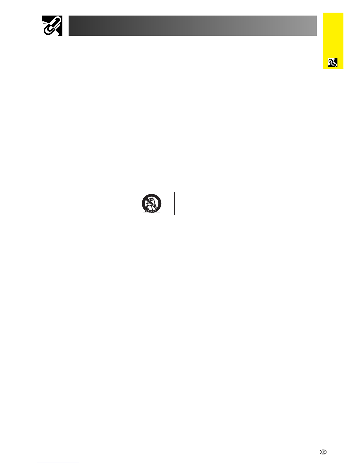
7. LCD Projector equipment and cart
combinations should be moved
with care. Quick stops, excessive
force, and uneven surfaces may
cause the equipment and cart
combination to overturn.
8. Slots and openings in the cabinet back and bottom are
provided for ventilation. To ensure reliable operation of
the LCD Projector and to protect it from overheating, these
openings must not be blocked or covered. The openings
should never be covered with cloth or other material.
9. This LCD Projector should never be placed near or over
a radiator or heating vent. The LCD Projector should not
be placed in a built-in installation such as a bookcase
unless proper ventilation is provided.
10. The LCD Projector should be operated only from the type
of power source indicated on the back of the projector or
in the specifications. If you are not sure of the type of
power supplied to your home, consult your LCD Projector
dealer or local power company.
11. Do not place the LCD Projector where the cord will be
abused by persons walking on it.
12. Follow all warnings and instructions marked on the LCD
Projector.
13. To prevent damage to the projector due to lightning and
power-line surges, unplug the projector from the power
outlet, when not in use.
14. Do not overload wall outlets and extension cords with too
many products, because this can result in fire or electric
shock.
15. Never push objects of any kind into the LCD Projector
through the cabinet slots as they may touch high-voltage
points or cause a short circuit. This could result in a fire
or electric shock.
16. Do not attempt to service the LCD Projector yourself.
Opening or removing covers may expose you to dangerous voltage or other hazards. Refer all servicing to
qualified service personnel.
3
Important
Information
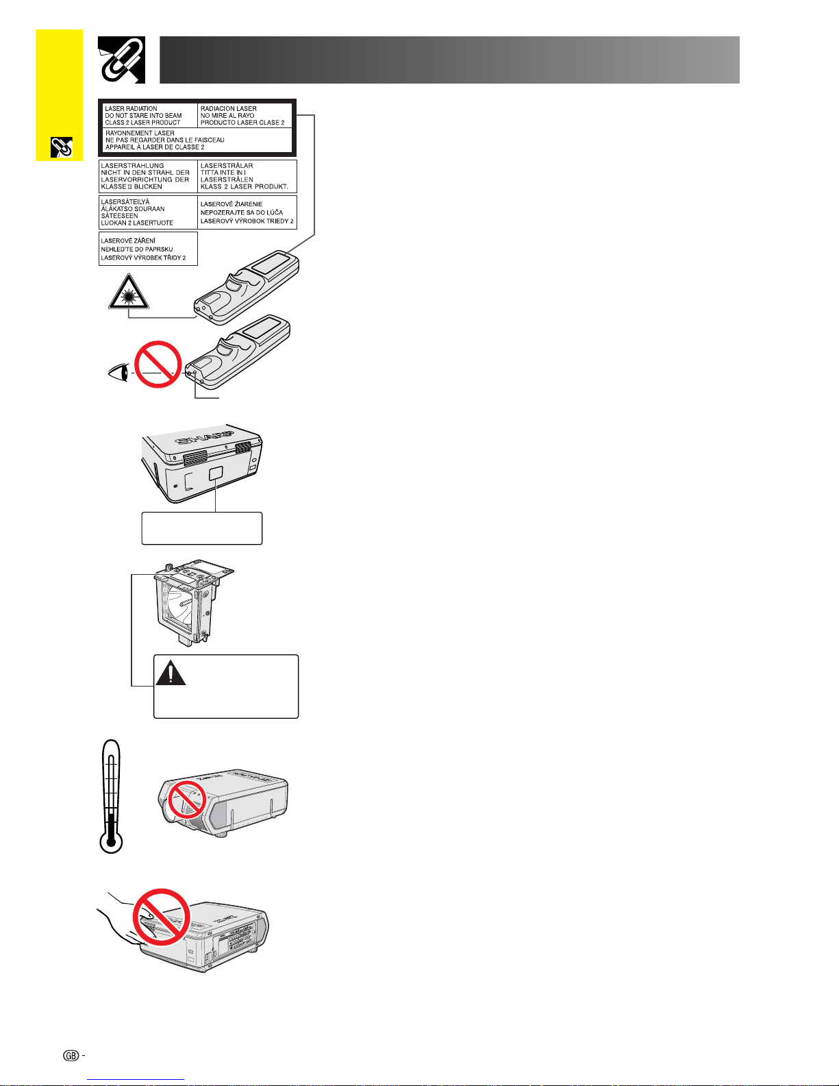
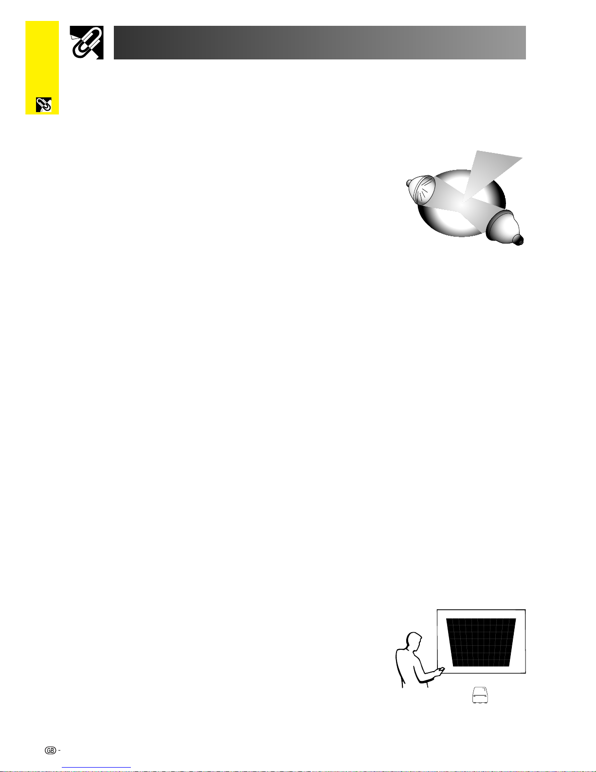
The laser pointer on the remote control emits a laser beam from the laser
pointer window. This is a Class II laser which may impair your sight if directed
into the eyes. The two marks shown on the left are caution labels for the laser
beam.
• Do not look into the laser pointer window or shine the laser beam on yourself or
others. (The laser beam used in this product is harmless when directed onto
the skin. However, be careful not to project the beam directly into the eyes.)
• Always use the laser pointer at temperatures between 5°C and 40°C.
• Use of controls or adjustments, or performance of procedures other than those
specified herein may result in hazardous radiation exposure.
Cautions Concerning the Laser Pointer
Caution Concerning the Lamp Replacement
See “Replacing the Lamp” on pages 71 and 72.
LAMP REPLACEMENT CAUTION
BEFOREREMOVING THE SC REW, DISCONNECT
POWER CORD. HOT SURFACE INSIDE ALLOW
1HOUR TO COOL BEFORE REPLACING THE
LAMP. SEE OPERATION MANUAL.
Caution Concerning the Lamp Unit
Potential hazard of glass particles if lamp ruptures. In case of lamp rupture,
contact your nearest Sharp Authorised LCD Projector Dealer or Service Centre
for a replacement.
See “Replacing the Lamp” on pages 71 and 72.
Important Safeguards
Laser pointer
window
CAUTION
POTENTIAL HAZARD OF GLASS
PARTICLES. SEE OPERATION MANUAL.
LAMP MAY RUPTURE.
ATTENTION
LAMPE. DANGER POTENTIEL DE PARTICULES DE
VERRE. SE REPORTER AU MODE D’EMPLOI.
RUPTURE POSSIBLE DE LA
Cautions Concerning the Setup of the Projector
For minimal servicing and to maintain high image quality, SHARP recommends
that this projector be installed in an area free from humidity, dust and cigarette
smoke. When the projector is subjected to these environments, the lens must
be cleaned more often. As long as the projector is regularly cleaned, use in
these environments will not reduce the overall operation life of the unit. Internal
cleaning should only be performed by a Sharp Authorised LCD Projector
Dealer or Service Centre.
• The exhaust vent, the lamp cage cover and adjacent areas may be extremely
hot during projector operation. To prevent injury, do not touch these areas until
they have sufficiently cooled.
• Allow at least 10 cm of space between the exhaust vent and the nearest wall or
obstruction.
• If the cooling fan becomes obstructed, a protection device will automatically
turn off the projector lamp. This does not indicate a malfunction. Remove the
projector power cord from the wall outlet and wait at least 10 minutes. Then
turn on the power by plugging the power cord back in. This will return the
projector to the normal operating condition.
Notes on Operation
40˚C
5˚C
4
Important
Information
Temperature Monitor Function
If the projector starts to overheat due to setup problems or a dirty air filter, “TEMP.”
and “
” will flash in the lower-left corner of the picture. If the temperature continues
to rise, the lamp will turn off, the TEMPERATURE WARNING indicator on the
projector will flash, and after a 90-second cooling-off period the power will shut
off. Refer to “Lamp/Maintenance Indicators” on page 69, for details.
• The cooling fan regulates the internal temperature, and its performance is
automatically controlled. The sound of the fan may change during projector
operation due to changes in the fan speed.
Lamp Monitor Function
When the projector is turned on after the lamp has been used for 900 hours,
“LAMP” and “
” will flash in the lower-left corner of the picture to advise you
to replace the lamp. Check the “Lamp Timer” menu to confirm which lamp
has been used for 900 hours and needs to be replaced. See pages 71 and
72 for lamp replacement. If the lamp has been used for 1,000 hours, the
projector power will automatically turn off and the projector will enter standby
mode. Refer to “Lamp/Maintenance Indicators” on page 69, for details.
Important Safeguards
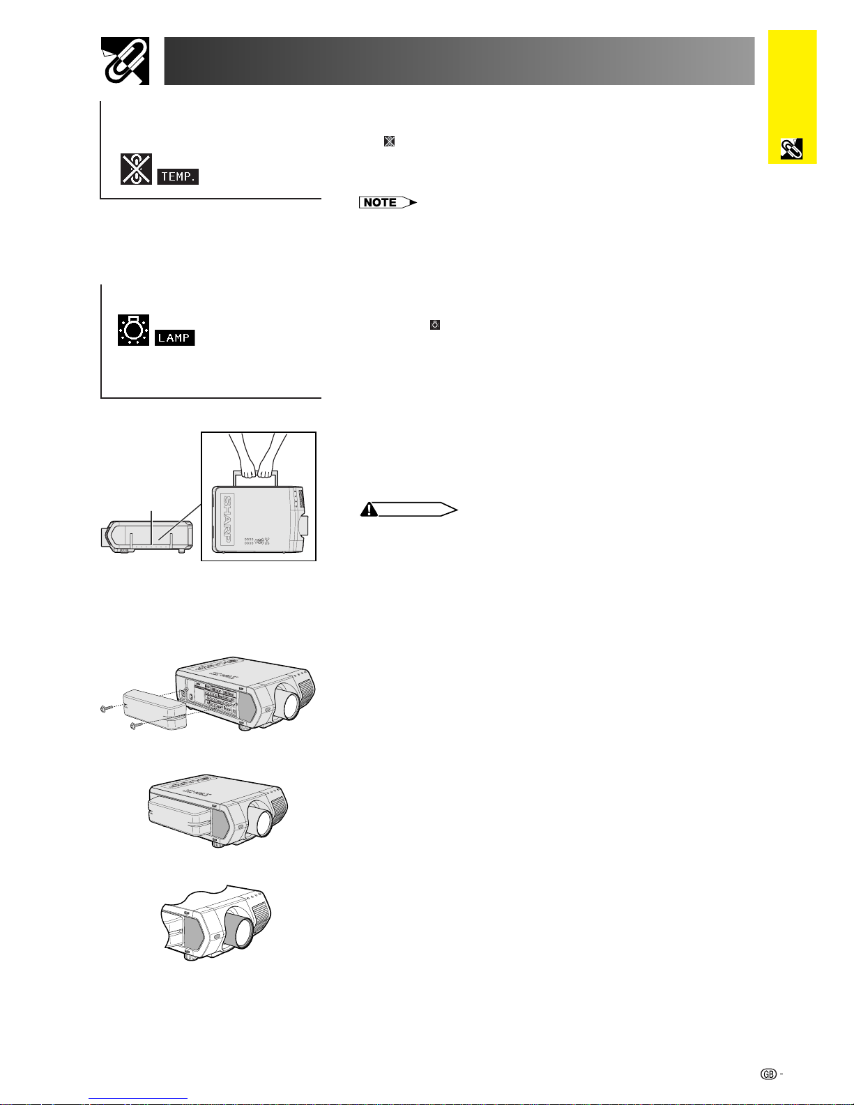
Using the Carrying Handle
When transporting the projector, carry it by the carrying handle on
the side.
CAUTION
• Always put on the lens cap to prevent damage to the lens when transporting
the projector.
• Do not lift or carry the projector by the lens or the lens cap as this may
damage the lens.
• This equipment is very heavy, so to prevent injury take special care when
carrying on your own.
• Do not put down the equipment when the BNC-RCA adapters are
connected.
Using the Terminal Cover
• When ceiling-mounting the projector, attach the terminal cover
(supplied) to hide the connecting cables.
• Use the terminal cover to hide the connecting cables when the
projector is used on a desktop or high mounted.
1 Attach the terminal cover by aligning with the tabs on the projector.
2 Install the terminal cover using the two supplied user service
screws attached.
s
Carrying handle
Optional lenses
• Lenses are sold separately.
• Be sure to have service personnel install optional lenses.
5
Important
Information
Outstanding Features
1. High-end LCD Projector with Ultra High Brightness
• 200 W UHP Lamps
Uses two 200 W UHP lamps for excellent colour uniformity and ultra high brightness.
• Newly developed prism enables efficient combination of light from two lamps.
A light axis separation and synthesis prism developed by Sharp enables the efficient
combination of light from the two lamps.
• Single-/Double-lamp Switching Feature
Projection can continue without interruption even if one
lamp burns out. Lamps can be used separately to double
the usage time.
2. Computer Compatibility
• Compatible with resolutions including VGA-XGA (expanded), SXGA (true
resolution) and UXGA (compressed) as well as DTV* formats (480i, 480P, 720P
and 1080i).
3. SXGA Image Quality
• OCS LCD panel enhances colour uniformity.
• Various other circuits are also used to provide high quality video images.
4. Computer & Video Integrated Composer Technology
• New Progressive Mode
I/P conversion with new algorithm used to achieve beautiful image quality.
• Enhanced Up-scaling and Digital Image Enlargement
Enables sharper image quality without jaggies even for enlarged images.
• Superior 16:9 Image
4:3 images can be converted to 16:9 images using Smart Stretch (sides stretched,
centre untouched), previously not achievable with LCD projectors.
• Intelligent Digital Keystone Correction
Smoothes out jaggies on keystone images and compresses the image not only
horizontally but vertically keeping the 4 : 3 aspect ratio, and at the same time,
calculates the aspect ratio automatically adjusting to the lens shift width.
• New Intelligent Compression
Efficiently compresses UXGA (1,600 1,200) images to SXGA (1,280 1,024).
• Enhanced three-two pull down
Converts cinema mode DVD images transformed with three-two pull down
enhancement to progressive mode images for easier viewing by Film Mode.
5. 3D Digital Uniformity and Digital Convergence
• Three-Dimensional Digital Uniformity compensates
uneven picture brightness even for pictures at any
brightness level from white to dark. And, with
Digital Convergence, a slight distortion of
convergence can be easily adjusted on the service
menu screen without having to touch the LCD
panel.
*DTV is the umbrella term used to describe the new digital television system in the united states.
6
Important
Information
Outstanding Features
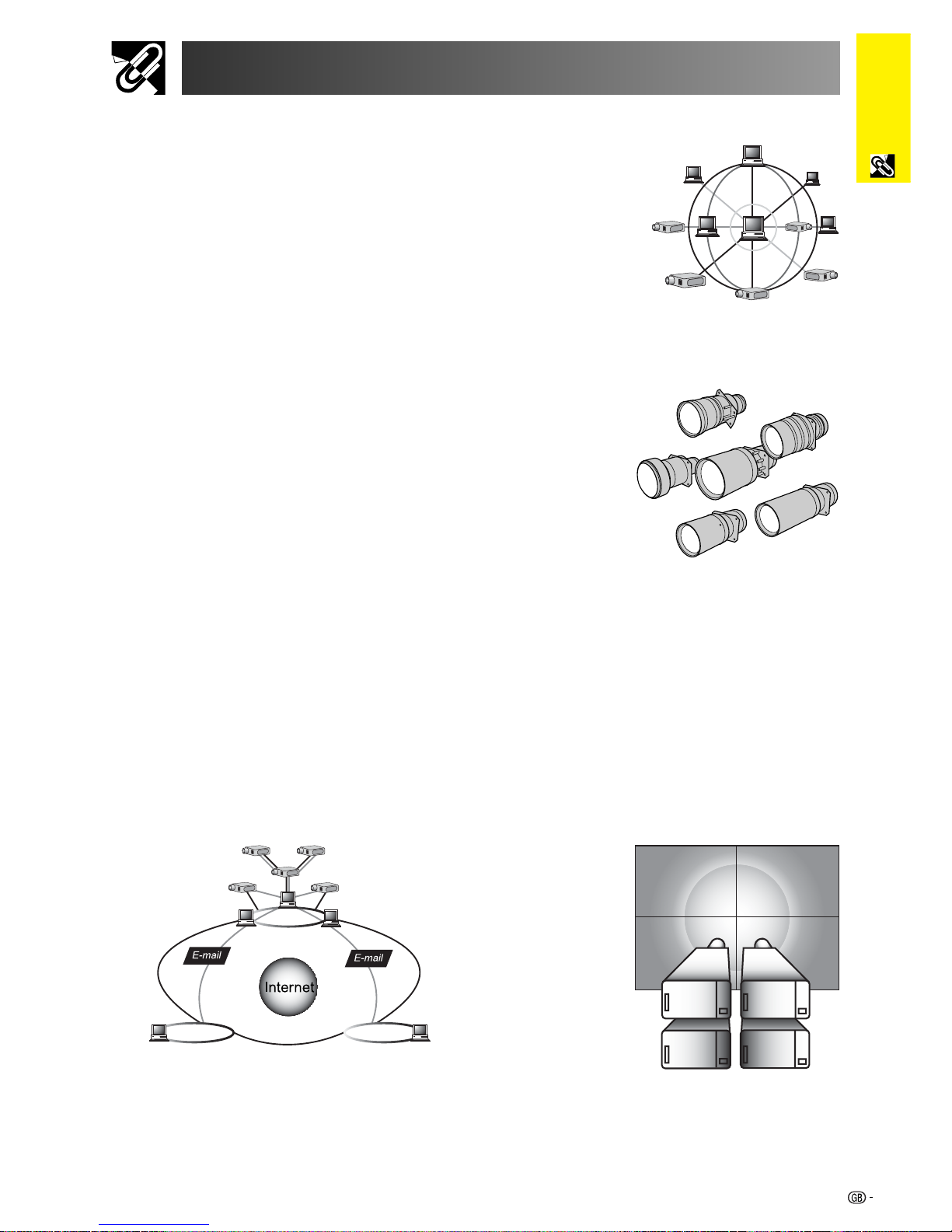
6. Network Capability
• Self-Diagnosis/Projector Status
Self-diagnosis/Projector status function sends e-mail
messages to a specified computer about lamp usage
time and any malfunctions.
• Multiple & Group Projector Control
Up to 250 projectors can be controlled over a network.
Projector RS-232C OUT can be used for daisy chain
connection.
• Simple Stacking and Videowall Display
Comes with software for easy stacking and videowall processing even for input from
a single source.
7. Six Optional Lenses for Maximum Flexibility
• Standard Zoom Lens, Fixed Wide Lens, Wide-Zoom
Lens, Mid-Range Zoom Lens, Tele-Zoom Lens,
Super Zoom Lens
8. Multiple Input and Output Terminals
• BNC Terminal for RGB/Component/Video Signal
• PC Digital Input (DVI)
• Expansion Terminal for Optional Boards
Board for Network Capability: RS-422 Board, LAN Board
(Soon-to-be-released)
Expansion Video Board: Serial Digital Interface (SDI) Board
9. Easy Setup
• Power Lens Shift, Power Zoom & Focus, Digital Keystone Correction
• High Speed AutoSync Technology (4 to 8 sec.)
10. Advanced Presentation Features
• Built-in Presentation Tools, Picture-in-Picture, Digital Enlargement, Freeze
• Customizable Startup Screen & Background Screen
11. Application Software
• “Sharp Advanced Presentation Software—Professional Edition” (Network and
Remote Control)
LAN
LAN LAN
7
Important
Information
Contents
Important Information
Introduction ............................................. 1
Important Safeguards ............................. 2
Outstanding Features ............................. 5
Contents ................................................... 7
How to Access the PDF Operation
Manuals ............................................... 9
Part Names............................................... 10
Supplied Accessories ............................. 13
Connections............................................. 14
Power Supply ............................................ 14
Projecting Computer Images .................... 14
Watching Video Images and
Laser Disc Images................................. 17
Watching DVD and Digital TV Images ...... 18
For Better Sound ....................................... 18
Power ON/OFF .......................................... 19
Setting Up the Screen ............................. 20
Using the Adjustment Feet ........................ 20
Adjusting the Projection Distance ............. 21
LENS Button .............................................. 29
Image Projection ..................................... 30
Rear Projection .......................................... 30
Projection Using a Mirror ........................... 30
Ceiling-mount Projection ........................... 30
Using the Operation Buttons ................. 31
Selecting the Input Signal Source ............. 31
Adjusting the Volume................................. 31
Muting the Sound ...................................... 31
Superimposing a Black Screen ................. 32
Displaying a Still Image ............................. 32
Magnifying a Specific Portion
of an Image .......................................... 33
Adjusting the Picture Aspect Ratio............ 34
Gamma Correction Function ..................... 35
Selecting the Remote Control Mode ......... 36
Operating the Remote Control .................. 36
Connecting the Mouse Receiver ............... 38
Using as a Laser Pointer ........................... 39
Using as a Wired Remote Control ............. 39
Setup &
Connections
Operation Buttons
Setup & Connections
Operation Buttons
Basic Operation
Useful Features &
Network Function
Appendix
Maintenance &
Troubleshooting
8
Important
Information
Contents
Basic Operation
Useful Features &
Network Function
Useful Features ....................................... 59
Locking the Operation Buttons
on the Projector.................................... 59
Deselecting Inputs .................................... 59
Selecting the Transmission Speed
(RS-232C) ............................................ 60
Protecting Important Settings
with a Password ................................... 61
Network Function .................................... 62
Setting Up the Optional Boards ................ 62
Controlling Multiple Projectors
with ID Numbers .................................. 63
Setting the Stacking Mode ........................ 63
Using the Presentation Tools ..................... 64
Operating the Network Function ............... 65
Maintenance &
Troubleshooting
Lamp/Maintenance Indicators ................ 69
Lamp Maintenance .................................. 70
Confirming the Lamp Usage Time ............ 70
Setting the Lamp Mode ............................. 71
Replacing the Lamp .................................. 71
Replacing the Air Filter ........................... 73
Troubleshooting ...................................... 74
Appendix
Guide to Effective Presentations ........... 75
Connecting Pin Assignments ................ 79
(RS-232C) Specifications and
Command Settings............................. 80
Wired Remote Control Terminal
Specifications ..................................... 83
Computer Compatibility Chart ............... 84
Dimensions .............................................. 85
Specifications .......................................... 86
Glossary ................................................... 87
Index ......................................................... 88
Using the GUI (Graphical User
Interface) Menu Screen ...................... 40
Basic Operations ....................................... 40
Menu Bars ................................................. 41
Adjusting the Picture ................................. 43
Adjusting the Computer Images
(RGB menu only) ................................. 46
Adjusting the Sound .................................. 50
Displaying Dual Pictures
(RGB menu only) ................................. 51
Reducing Image Noise
(VIDEO menu only) .............................. 52
Turning On/Off the On-screen Display ...... 53
Setting the Video Signal
(VIDEO menu only) .............................. 53
Selecting a Background Image................. 54
Selecting a Startup Image ......................... 54
Selecting the Economy Mode ................... 55
Reversing/Inverting Projected Images ...... 56
Selecting the On-screen Display
Language ............................................ 57
Displaying the Adjustment Settings .......... 58
Setup & Connections Operation Buttons Basic Operation
Maintenance &
Troubleshooting
Appendix
Useful Features &
Network Function

9
Important
Information
How to Access the PDF Operation Manuals
PDF operation manuals in several languages are included in the CD-ROM. To utilize these manuals, you need to
install Adobe Acrobat Reader on your PC (Windows or Macintosh). If you have not installed Acrobat Reader yet,
you can download it from the Internet (http://www.adobe.com) or install it from the CD-ROM.
To Install Acrobat Reader from the CD-ROM
For other operating systems:
Please download Acrobat Reader from the Internet (http://www.adobe.com).
For other languages:
If you prefer using Acrobat Reader for languages other than those included in the CD-ROM, please download the
appropriate version from the Internet.
Accessing the PDF Manuals
For Windows:
1 Insert the CD-ROM in the CD-ROM drive.
2 Double click on the “My Computer” icon.
3 Double click on the “CD-ROM” drive.
4 Double click on the “manuals” folder.
5 Double click on the “acrobat” folder.
6 Double click on the “windows” folder.
7 Double click on the desired installation
programme and follow the instructions on the
screen.
For Macintosh:
1 Insert the CD-ROM in the CD-ROM drive.
2 Double click on the “CD-ROM” icon.
3 Double click on the “manuals” folder.
4 Double click on the “acrobat” folder.
5 Double click on the “mac” folder.
6 Double click on the desired installation
programme and follow the instructions on the
screen.
For Windows:
1 Insert the CD-ROM in the CD-ROM drive.
2 Double click on the “My Computer” icon.
3 Double click on the “CD-ROM” drive.
4 Double click on the “manuals” folder.
5 Double click on the “xg-v10we” folder.
6 Double click on the language (name of the
folder) that you want to view.
7 Double click on the “v10” pdf file to access the
projector manuals.
Double click on the “saps” pdf file to access the
Sharp Advanced Presentation Software manual.
8 Double click on the pdf file.
For Macintosh:
1 Insert the CD-ROM in the CD-ROM drive.
2 Double click on the “CD-ROM” icon.
3 Double click on the “manuals” folder.
4 Double click on the “xg-v10we” folder.
5 Double click on the language (name of the
folder) that you want to view.
6 Double click on the “v10” pdf file to access the
projector manuals.
Double click on the “saps” pdf file to access the
Sharp Advanced Presentation Software manual.
7 Double click on the pdf file.
• If the desired pdf file cannot be opened by double clicking the mouse, start Acrobat Reader first, then specify the desired file
using the “File”, “Open” menu.
• See the “readme.txt” file on the CD-ROM for important information on the CD-ROM not included in this operation manual.

10
Important
Information
Part Names
Projector
Numbers next to the part names refer to the main pages in this manual where the topic is explained.
Front and Top View
LENS button
POWER buttons (ON/OFF)
ENTER button
INPUT 1, 2, 3 button
FREEZE button
ENLARGE button
UNDO button
MUTE button
VOLUME buttons (/)
INPUT 4, 5, 6 button
GAMMA button
RESIZE button
AUTO SYNC button
Remote control sensor
Lens (sold separately)
Air filter (Intake vent)
Carrying handle
POWER indicator
TEMPERATURE WARNING indicator
LAMP 1 REPLACEMENT indicator
LAMP 2 REPLACEMENT indicator
MENU button
ADJUSTMENT buttons
(∂/ƒ/ß / ©)
Adjuster
19
29
40
31
32
33
40
31
31
40
40
31
49
34
35
4
20
36
21
73
19
69
69
69
11
Important
Information
14
19
62
17
17
17
18
39
16
14
15
14
6268
16
3
36
63
Part Names
Projector
Numbers next to the part names refer to the main pages in this manual where the topic is explained.
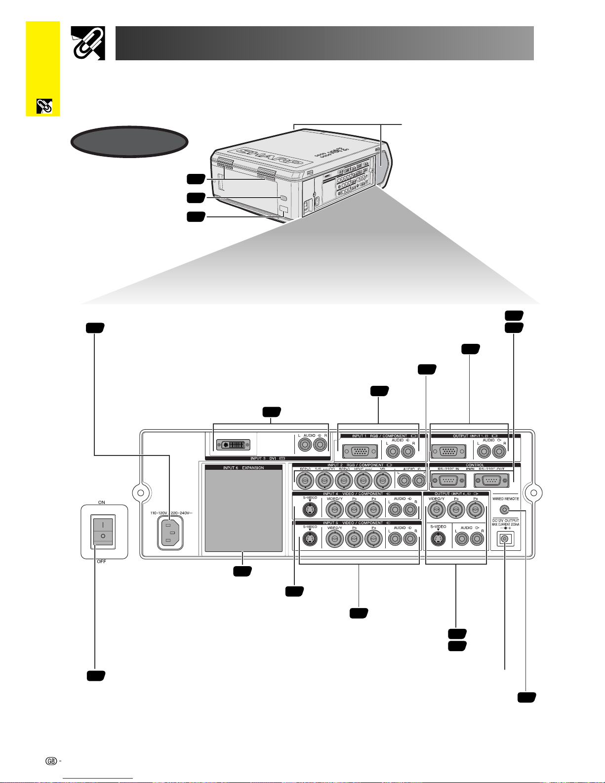
Side and Rear View
Speakers
Exhaust vent
Remote control sensor
LED display (ID No.)
RS-232C INPUT port/
RS-232C OUTPUT port
AC socket
MAIN POWER switch
OUTPUT port (15-pin Mini D-sub) for INPUT 1, 2/
AUDIO OUTPUT terminals for INPUT 1, 2
INPUT 1 port (15-pin Mini D-sub)/
AUDIO INPUT 1 terminals
INPUT 3 port (DVI)/
AUDIO INPUT 3 terminals
INPUT 6 EXPANSION board
S-VIDEO INPUT 4 terminal (4-pin Mini DIN)/
INPUT 4 terminals/AUDIO INPUT 4 terminals
S-VIDEO INPUT 5 terminal (4-pin Mini DIN)/
INPUT 5 terminals/AUDIO INPUT 5 terminals
OUTPUT terminals for INPUT 4, 5/
S-VIDEO OUTPUT terminal for INPUT 4, 5 (4-pin Mini DIN)/
AUDIO OUTPUT terminals for INPUT 4, 5
DC 12V OUTPUT
WIRED REMOTE control input terminal
INPUT 2 terminals/AUDIO INPUT 2 terminals
12
Important
Information
Part Names
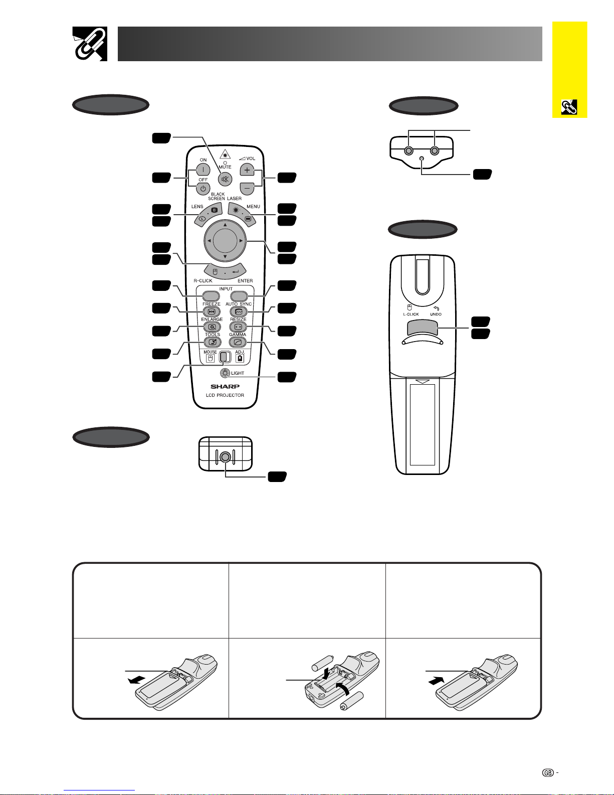
Inserting the batteries
13
Press in on the arrow
mark and slide in the
direction of the arrow to
remove the battery cover.
2
Insert two AA size
batteries, making sure
the polarities match the
and marks inside
the battery compartment.
Insert the side tabs of
the battery cover into the
slots and press the
cover in until it is
properly seated.
Battery
compartment
Battery
cover
Battery
cover
1.2.3 4.5.6
Conference Series
31
19
31
32
33
64
36
31
29
39
37
37
32
40
40
40
31
49
34
35
37
VOLUME buttons
(/)
BACKLIGHT button
MUTE button
Bottom View
39
POWER buttons
(ON/OFF)
LASER POINTER/
MENU button
LENS/BLACK
SCREEN button
RIGHT-CLICK/
ENTER button
INPUT 4, 5, 6 buttonINPUT 1, 2, 3 button
AUTO SYNC button
FREEZE button
RESIZE buttonENLARGE button
GAMMA buttonTOOLS button
MOUSE/
ADJUSTMENT
switch
Wired remote control
input
LEFT-CLICK/
UNDO
button
37
40
MOUSE/
ADJUSTMENT
buttons (∂/ƒ/ß/©)
3
Remote control
signal transmitter
Laser
pointer
window
Front View
Top View
Bottom View
Remote Control
Rear View
13
Important
Information
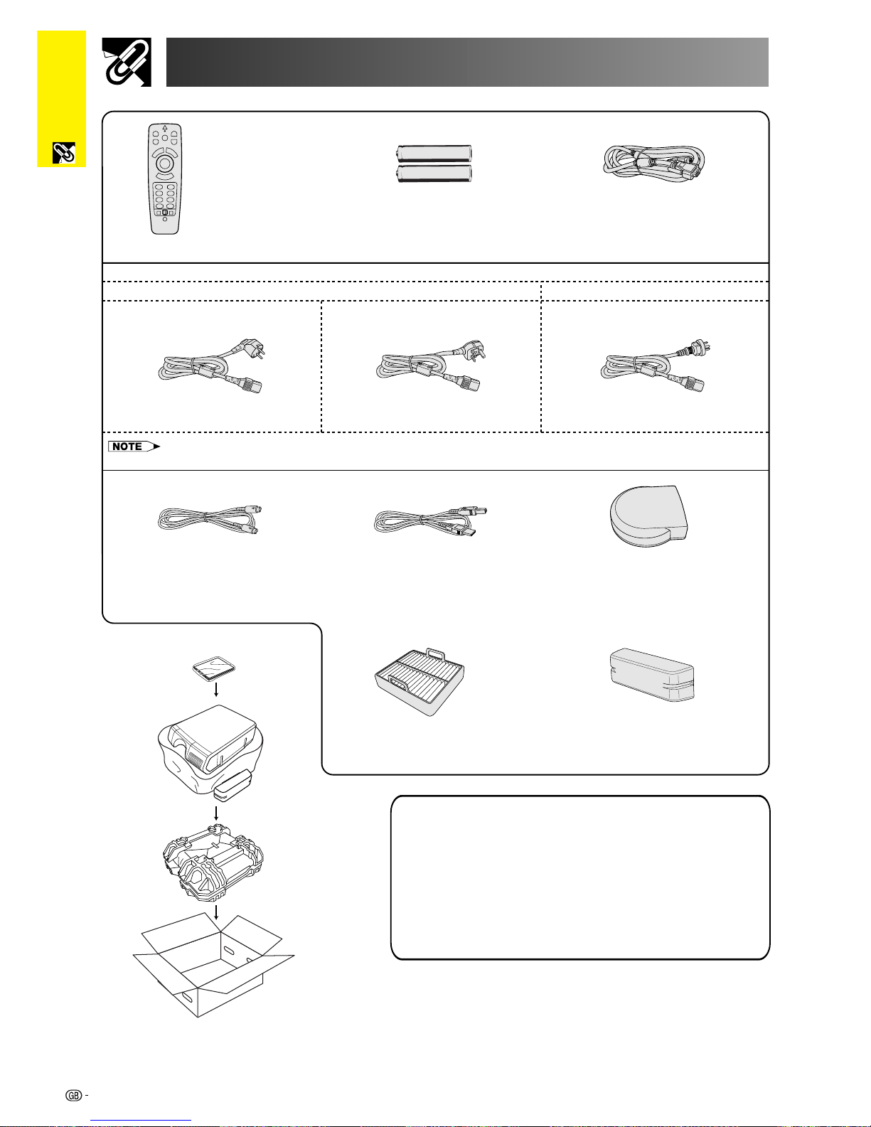
Supplied Accessories
Remote control RGB cableTwo AA size batteries
Extra air filter
Power cord
For Europe, Hong Kong and Singapore
For Australia, New Zealand and Oceania
• The configuration of wall outlets differs from country to country. Use the power cord that corresponds to the wall outlet in your country.
PS/2 mouse control cable USB mouse control cable Remote mouse receiver
Terminal cover
CD-ROM
LCD projector operation manual
LCD projector quick references
Sharp Advanced Presentation Software operation manual
For Europe, except U.K. For U.K., Hong Kong and Singapore
14
Setup & Connections
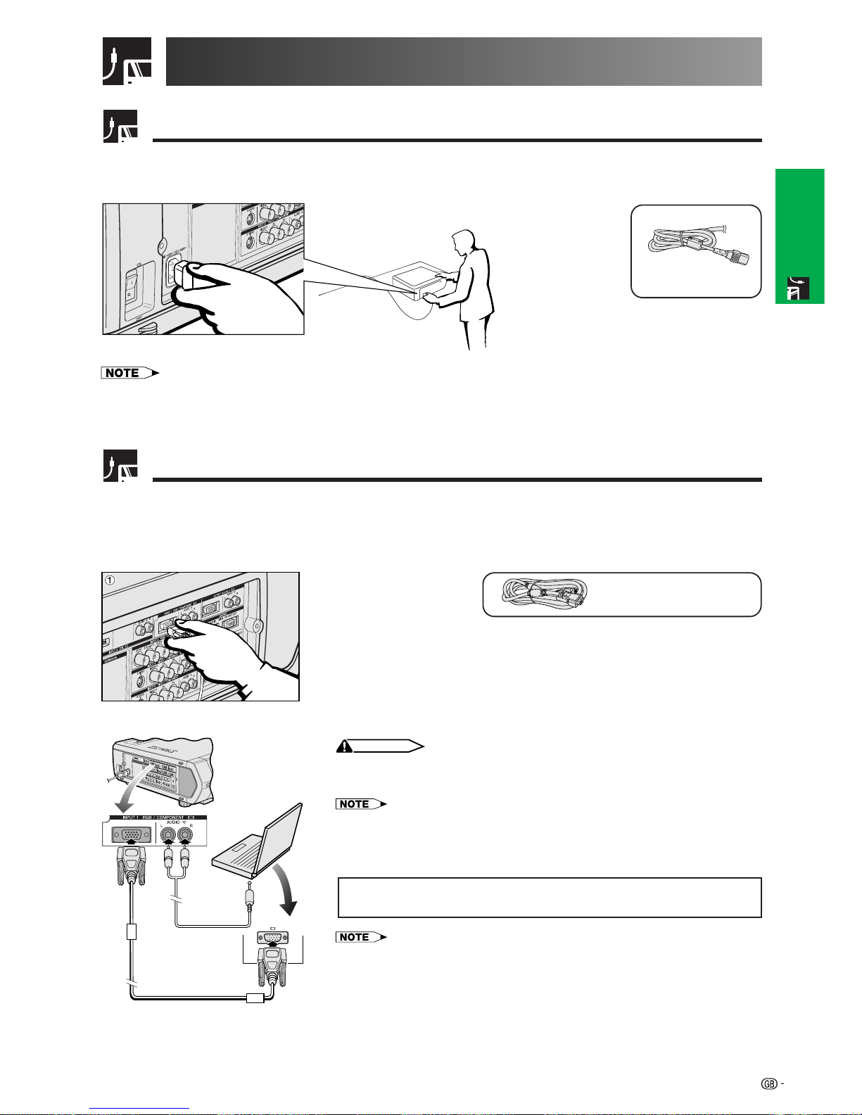
Power Supply
Connecting the Power Cord
Plug the supplied power cord into the AC socket on the side of the projector.
Projecting Computer Images
Connecting the Projector to a Computer
You can connect your projector to a computer for projection of full colour computer images.
Connecting to a computer using the standard 15-pin Input
RGB cable
1 Connect one end of the supplied RGB cable to the INPUT 1 port on the
projector.
2 Connect the other end to the monitor output port on the computer. Secure the
connectors by tightening the thumb screws.
3 To use the built-in audio system, connect one end of the audio cable (sold
separately) to the AUDIO INPUT 1 terminal on the projector.
4 Connect the other end to the audio output terminal on the computer.
CAUTION
• Before connecting, be sure to turn both the projector and the computer off. After making
all connections, turn the projector on first. The computer should always be turned on
last.
• Please read the computer’s operation manual carefully before making connections.
• Refer to page 84 “Computer Compatibility Chart” for a list of computer signals compatible
with the projector. Use with computer signals other than those listed may cause some of
the functions not to work.
• A 3.5 mm stereo minijack to stereo RCA audio cable adaptor may be necessary.
When connecting this projector to a computer, select “RGB” for “Signal Type”
on the GUI menu. (See page 45.)
• A Macintosh adaptor may be required for use with some Macintosh computers. Contact
your nearest Sharp Authorised LCD Projector Dealer or Service Centre.
• AUDIO INPUT 1 can be used to input audio corresponding to the INPUT 1.
Connections
Power cord
13
4
2
• The configuration of wall outlets differs from country to country. Use the power cord that corresponds to the wall outlet in your
country.
15
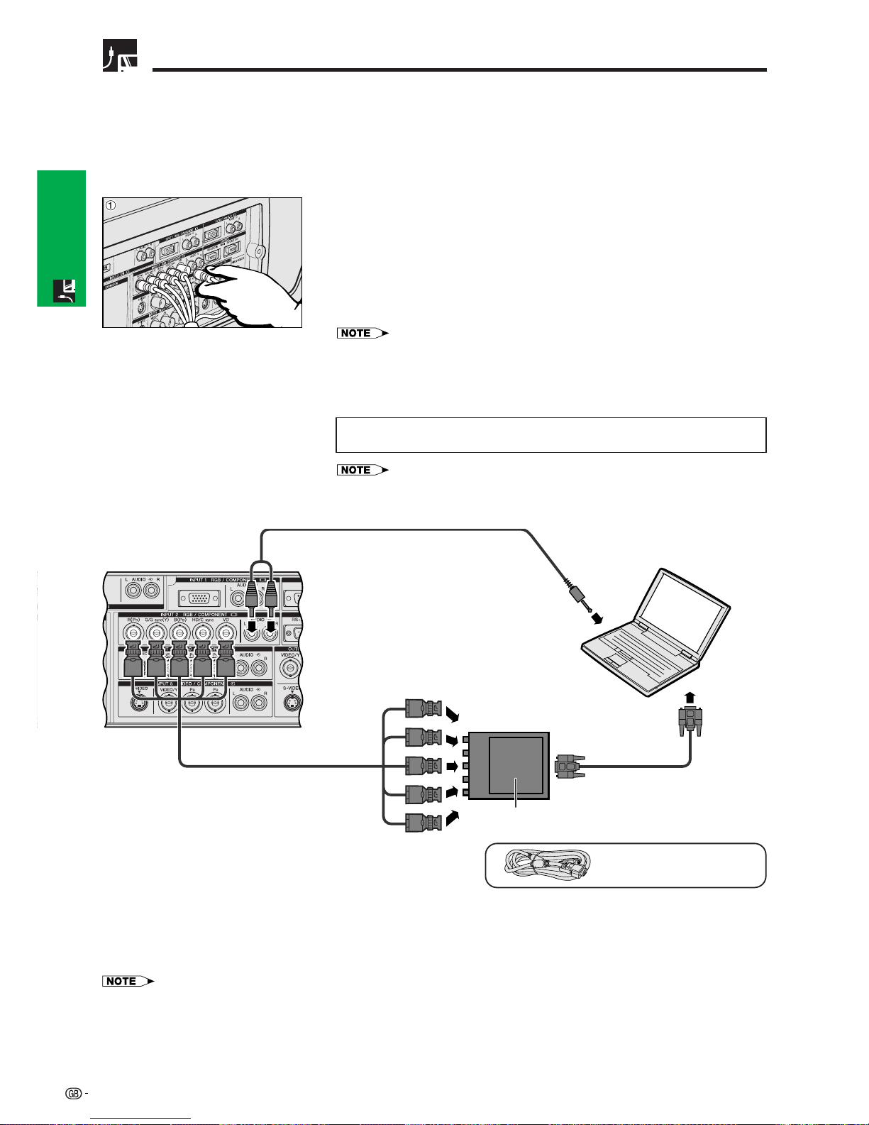
Setup & Connections
Projecting Computer Images
• This projector uses a 5 BNC computer input to prevent deterioration of image quality.
• Connect the R (P
R), G/G sync (Y), B (PB), HD/C sync and VD cables (sold separately) to the correct input
terminals on the projector and an RGB switcher (sold separately) connected to the computer, or connect a 5
BNC cable (sold separately) directly from the input terminals on the projector to the computer.
Connecting to an external RGB switcher or other compatible computers using the BNC Input
(Typically used in larger installations )
1 Connect each BNC connector of a 5 BNC cable to the corresponding INPUT
2 terminals on the projector.
2 Connect the other end of the 5 BNC cable to the corresponding BNC terminals
on the external RGB switcher.
Connect the RGB switcher to the computer using a RGB cable.
3 To use the built-in audio system, connect one end of the audio cable (sold
separately) to the AUDIO INPUT 2 terminal on the projector.
4 Connect the other end to the audio output terminal on the computer or external
audio system.
• A 3.5 mm stereo minijack to stereo RCA audio cable adaptor may be necessary.
When connecting the projector to a compatible computer other than a PC (VGA/
SVGA/XGA/SXGA/UXGA) or Macintosh (i.e. Workstation), a separate cable may
be needed. Please contact your dealer for more information.
When connecting this projector to a computer, select “RGB” for “Signal Type”
on the GUI menu. (See page 45.)
• Connecting computers other than the recommended types may result in damage to the
projector, the computer, or both.
• AUDIO INPUT 2 can be used to input audio corresponding to the INPUT 2.
“Plug and Play” function (when connecting to a 15-pin terminal)
• This projector is compatible with VESA-standard DDC 1/DDC 2B. The projector and a VESA DDC compatible
computer will communicate their setting requirements, allowing for quick and easy setup.
• Before using the “Plug and Play” function, be sure to turn on the projector first and the connected computer last.
• The DDC “Plug and Play” function of this projector operates only when used in conjunction with a VESA DDC compatible computer.
2 To RGB switcher
5 BNC cable
(sold separately)
RGB cable
4 To audio output
terminal
To R (P
R), G/G sync (Y), B (PB),
HD/C sync and VD output terminals
RGB cable
RGB switcher
(sold separately)
3
1
Audio cable
(3.5 mm stereo minijack/RCA cable,
sold separately)
16
Setup & Connections
Projecting Computer Images
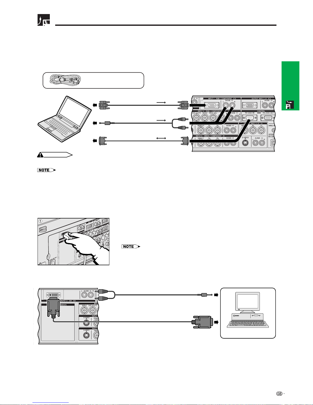
Connecting to a computer using the RS-232C Port
When the RS-232C port on the projector is connected to a computer with an RS-232C cable (null modem, cross
type, sold separately), the computer can be used to control the projector and check the status of the projector.
See pages 80, 81 and 82 for details.
Connect an RS-232C cable (null modem, cross type, sold separately) to the serial port on the computer.
RGB cable
CAUTION
• Do not connect or disconnect an RS-232C cable to or from the computer while it is on. This may damage your computer.
• The wireless mouse or RS-232C function may not operate if your computer port is not correctly set up. Please refer to the operation manual
of the computer for details on setting up/installing the correct mouse driver.
• The arrows (→, ↔) indicate the direction of the signals.
• A Macintosh adaptor may be required for use with some Macintosh computers. Contact your nearest Sharp Authorised LCD Projector
Dealer or Service Centre.
Connecting to a computer using the direct digital input port
1 Connect one end of the DVI cable to the INPUT 3 port on the projector.
2 Connect the other end to the corresponding terminal on a computer.
3 To use the built-in audio system, connect one end of an audio cable (sold
separately) to AUDIO INPUT 3 terminal on the projector.
4 Connect the other end to the audio output terminal on the computer.
• This DVI port is DVI version 1.0 compatible. Therefore when the signal is input from copy
guard system compatible (DVI version 2.0) equipment, no signal will be received.
RGB cable
Audio cable
(3.5 mm stereo minijack/RCA cable,
sold separately)
RS-232C cable (null modem,
cross type, sold separately)
Computer
DVI cable (sold separately)
4 To audio output terminal
2 To digital output terminal
Audio cable
(3.5 mm stereo minijack/RCA cable,
sold separately)
3
17
Setup & Connections
Watching Video Images and Laser Disc Images
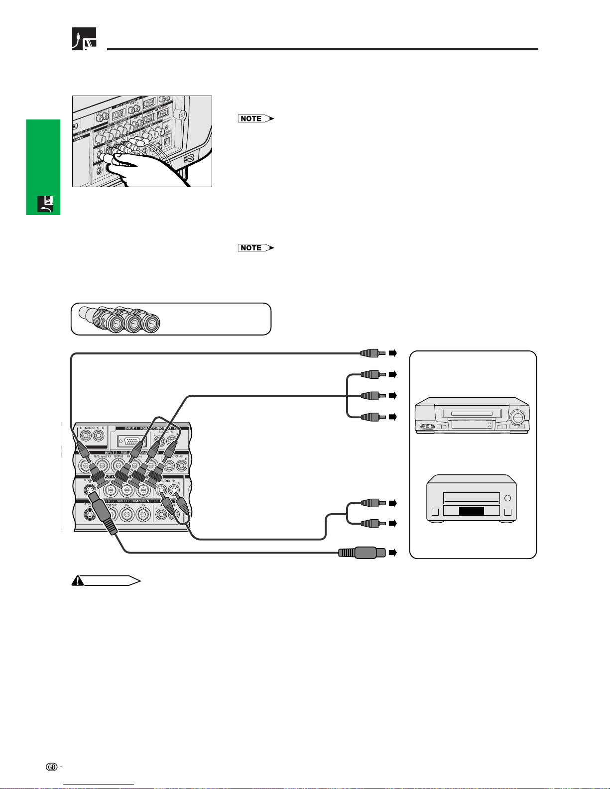
Connecting to a VCR, laser disc player and other audiovisual equipment using
the BNC video Input
1 Connect each BNC connector of a component or video cable to the
corresponding BNC INPUT 4 or 5 terminals on the projector.
• BNC-RCA adaptors are needed for use with RCA type cables and sources.
2 Connect the other end of the cable to the corresponding terminals on a VCR
or laser disc player.
3 To use the built-in audio system, connect one end of an audio cable (sold
separately) to AUDIO INPUT 4 or 5 terminal on the projector.
4 Connect the other end to the audio output terminal on the video component.
The S-VIDEO INPUT terminal uses a video signal system in which the picture is
separated into a colour and a luminance signal to realise a higher-quality image.
When cables are connected to both the S-VIDEO INPUT 4 or 5 and VIDEO INPUT
4 or 5 terminals, images input through the S-VIDEO INPUT 4 or 5 terminal have
priority over images input through the VIDEO INPUT 4 or 5 terminal.
• For higher quality video, you may use the S-VIDEO INPUT terminal on the projector. Svideo cable is sold separately.
• If your video equipment does not have an S-video output terminal, use a composite video
cable.
Three BNC-RCA adaptors
(Sold separately)
2 To video
output terminals
Video cable (sold separately)
2 To analog component
output terminals
VCR
or
Laser disc player
CAUTION
• Always turn off the projector before connecting to video equipment, in order to protect both the projector and the equipment
being connected.
S-video cable (sold separately)
To S-video output terminal
3
Audio cable
(sold separately)
11
Component cable (sold separately)
or
4 To audio
output terminals
18
Setup & Connections
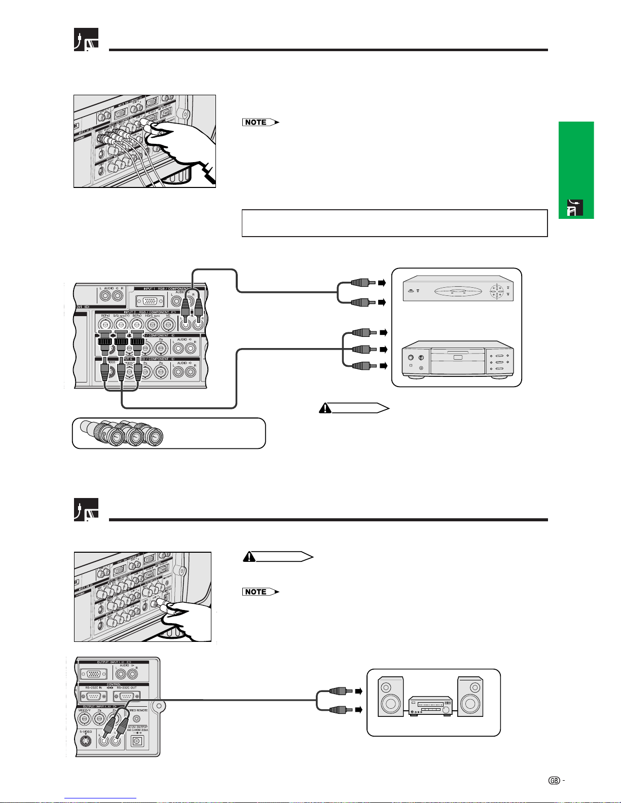
Watching DVD and Digital TV Images
1 Connect each BNC connector of a component cable to the corresponding
BNC INPUT 2 terminals on the projector.
• BNC-RCA adaptors are needed for use with RCA type cables and sources.
2 Connect the other end of the cable to the corresponding terminals on a DVD
player or DTV decoder.
3 To use the built-in audio system, connect one end of an audio cable (sold
separately) to the AUDIO INPUT 2 terminal on the projector.
4 Connect the other end to the audio output terminal on the DVD player or DTV
decorder.
When connecting this projector to a DVD player or DTV decoder, select
“Component” for “Signal Type” on the GUI menu. (See page 45.)
Connecting to a DVD player, DTV* decoder and other component video
equipment using the 5 BNC Input
DTV decoder
or
DVD player
Amplifier
To audio input terminals
Audio cable (sold separately)
For Better Sound
Connecting to an amplifier and other audio components
CAUTION
• Always turn off the projector before connecting to audio components, in order
to protect both the projector and the components being connected.
• By using external audio components, the volume can be amplified for better sound.
• The AUDIO OUTPUT terminals allow you to output audio to audio components from the
selected AUDIO INPUT 1 to 5 terminals connected to audiovisual equipment.
Three BNC-RCA adaptors
(Sold separately)
CAUTION
• Always turn off the projector before connecting to video
equipment, in order to protect both the projector and the
equipment being connected.
3
2 To analog component
output terminals
1
4 To audio output terminals
Component cable (sold separately)
e.g. Outputs for Inputs 4, 5
Audio cable
(sold separately)
*DTV is the umbrella term used to describe the new digital television system in the united states.
19
Setup & Connections
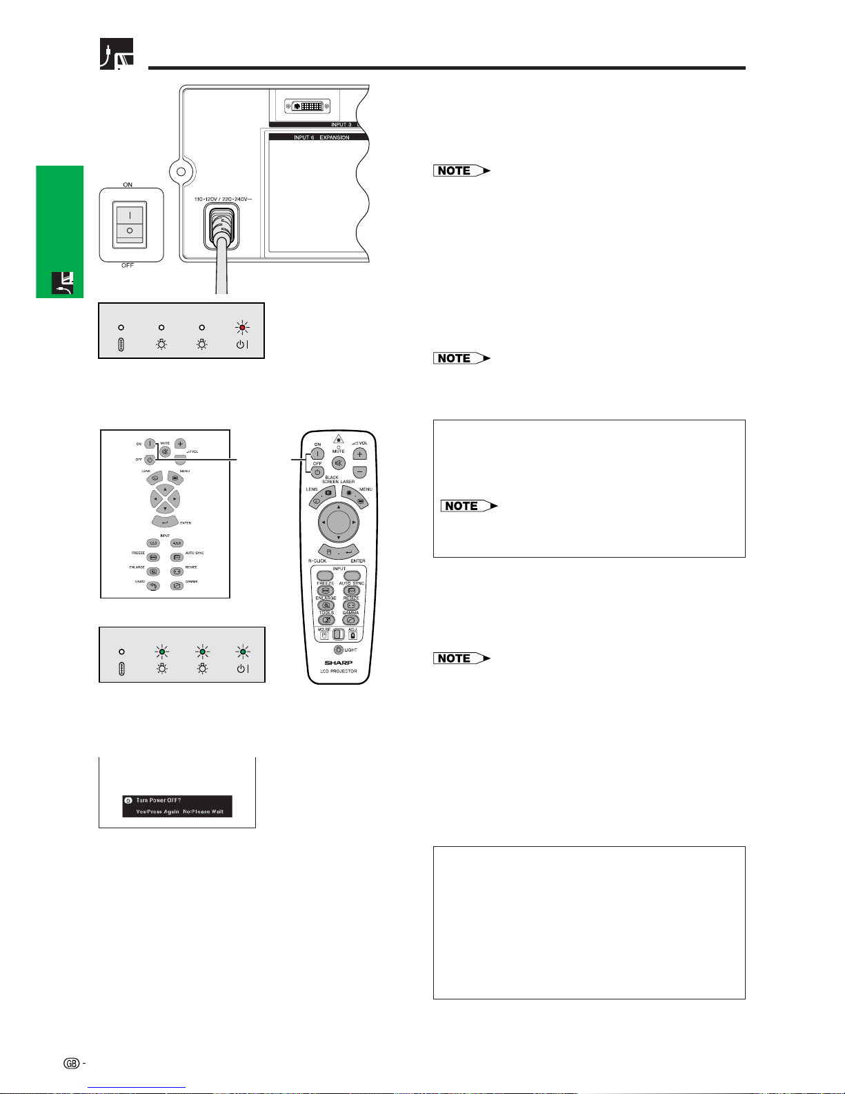
Power ON/OFF
Press the MAIN POWER switch on the side of the
projector. The POWER indicator lights up red and the
projector enters standby mode.
• When the main power is not on, the remote control cannot
be used to operate the projector.
Turning on the Main Power
TEMP LAMP2 LAMP1 POWER
2 1
Press POWER ON.
• The flashing green LAMP REPLACEMENT indicator
shows that the lamp is warming up. Wait until the
indicator stops flashing before operating the projector.
• If the power is turned off and then immediately turned
on again, it may take a short while before the lamp
turns on.
• After the projector is unpacked and turned on for the first
time, a slight odour may be emitted from the exhaust
vent. This odour will soon disappear with use.
When the power is on, the LAMP REPLACEMENT
indicator lights, indicating the status of the lamp.
Green: Lamp is ready.
Flashing green: Warming up.
Red: Change the lamp.
• When setting the lamp mode to “Lamp 1 only” or “Lamp
2 only”, only the LAMP REPLACEMENT indicator
corresponding to the lamp set is lit.
TEMP LAMP2 LAMP1 POWER
2 1
POWER
buttons
1.2.3 4.5.6
Conference Series
Press POWER OFF.
Press POWER OFF again while the message is
displayed.
• If you accidentally pressed POWER OFF and do not want
to turn off the power, wait until the power off screen
disappears.
• When POWER OFF is pressed twice, the POWER indicator
will light up red and the cooling fan will run for about 90
seconds. The projector will then enter standby mode.
• Wait until the cooling fan stops before disconnecting the
power cord.
• The power can be turned on again by pressing POWER
ON. When the power is turned on, the POWER indicator
and the LAMP REPLACEMENT indicators light green.
• The POWER indicator flashes if the front filter is not securely
installed.
WARNING:
The cooling fan in this projector continues to run for
about 90 seconds after the projector is turned off.
During normal operation, when turning the power off
always use the POWER OFF button on the projector or
the remote control. Ensure the cooling fan has stopped
before disconnecting the power cord.
DURING NORMAL OPERATION, NEVER TURN THE
PROJECTOR OFF BY DISCONNECTING THE POWER
CORD. FAILURE TO OBSERVE THIS WILL RESULT IN
PREMATURE LAMP FAILURE.
20
Setup & Connections
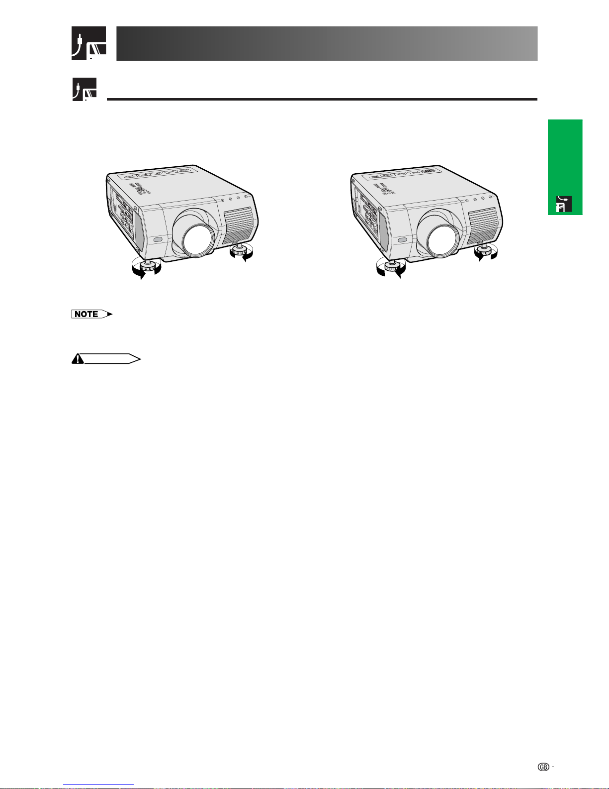
Using the Adjustment Feet
Setting Up the Screen
Using the Adjustment Feet
Rotate feet to adjust height of the projector.
• The projector is adjustable up to approximately 5° from the standard position.
• When the height of the projector is adjusted, the image may become distorted (keystoned), depending on the relative
positions of the projector and the screen.
CAUTION
• Do not hold the lens when lifting or lowering the projector.
• When lowering the projector, be careful not to get your fingers caught in the area between the adjustment feet and the
projector.
Up Down
21
Setup & Connections
Adjusting the Projection Distance
Position the projector perpendicular to the screen with all feet flat and level to achieve an optimal image.
Move the projector forward or backward if the edges of the image are distorted.
• The projector lens should be centred in the middle of the screen. If the lens centre is not perpendicular to the screen, the image will be
distorted, making viewing difficult.
• Position the screen so that it is not in direct sunlight or room light. Light falling directly onto the screen washes out colours, making viewing
difficult. Close the curtains and dim the lights when setting up the screen in a sunny or bright room.
• A polarizing screen cannot be used with this projector.
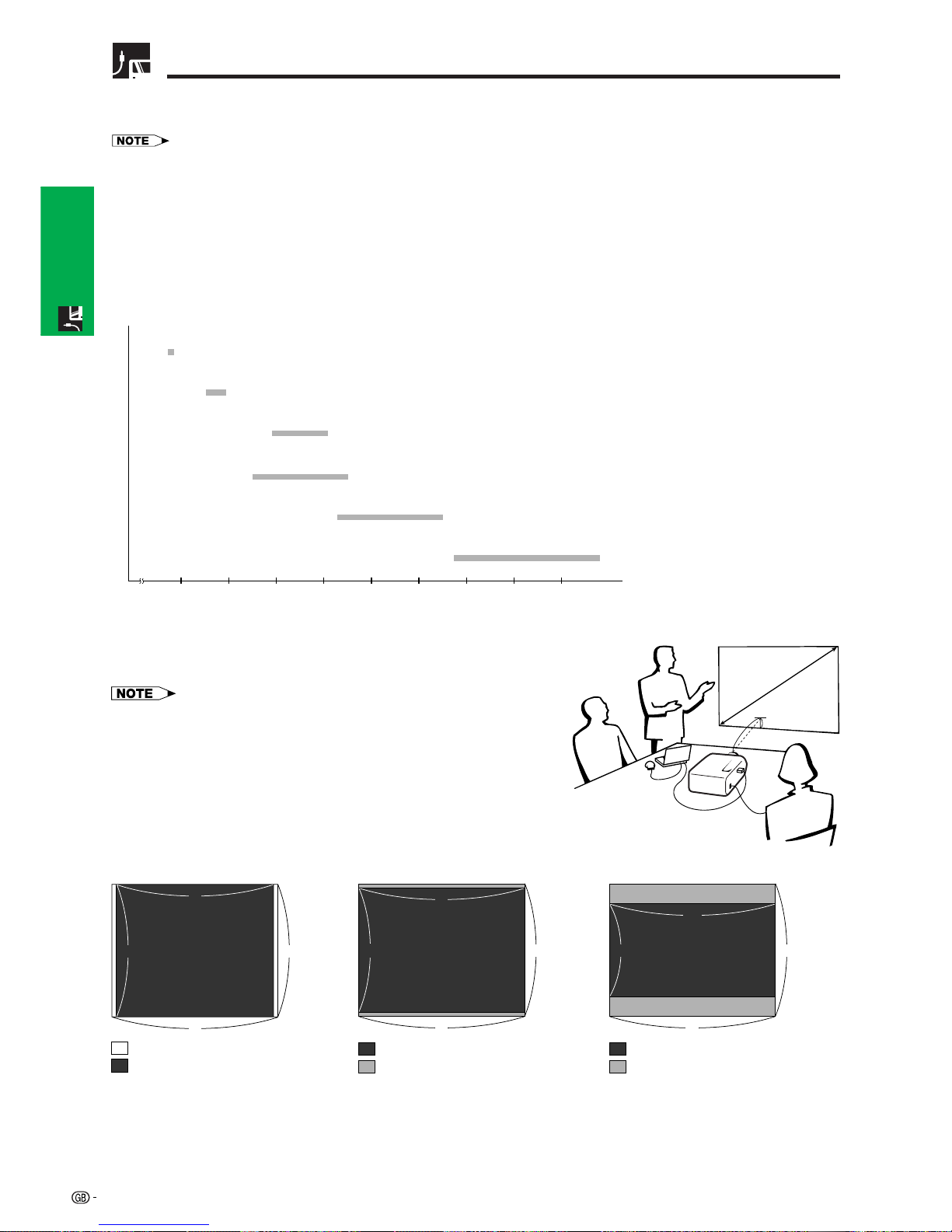
Six optional lenses from Sharp are also available for specialised application. Please see your local Sharp Authorised
LCD Projector Dealer for details on all the lenses. (Refer to the lens operation manual when attaching a lens.)
Be sure to have service personnel install optional lenses.
2345678910 (m)
Screen
AN-LV80EZ
7.7–10.8 m
Throw distance ratio 3.8–5.3:1
AN-LV55EZ
5.3–7.5 m
Throw distance ratio 2.6–3.7:1
AN-LV36EZ
3.5–5.5 m
Throw distance ratio 1.7–2.7:1
AN-LV40EZ
3.9–5.1 m
Throw distance ratio 1.9–2.5:1
AN-LV26EZ
2.5–2.9 m
Throw distance ratio 1.2–1.4:1
AN-LV18MX
1.7 m
Throw distance ratio 0.9:1
Throw Distance
Place the projector at the required distance from the screen according
to the desired picture size. (See pages 22–27.)
• Six optional lenses from Sharp are available for specialised application.
Please see your local Sharp Authorised LCD Projector Dealer for details
on all the lenses.
Standard Setup (Front Projection)
H
L
X
Computer Input (5:4)
4
5
4 3
Video Input (16:9)
: Screen size and Picture size (4:3)
: Signal mask area
: Screen size and Picture size (16:9)
: Signal mask area
e.g. Screen size: 254 cm (100 inches)
Computer Input: 5:4
5
16
9 4
Video Input (4:3)
5
4
3 4
: Screen size (4:3)
: Picture size (5:4)
22
Setup & Connections
Adjusting the Projection Distance
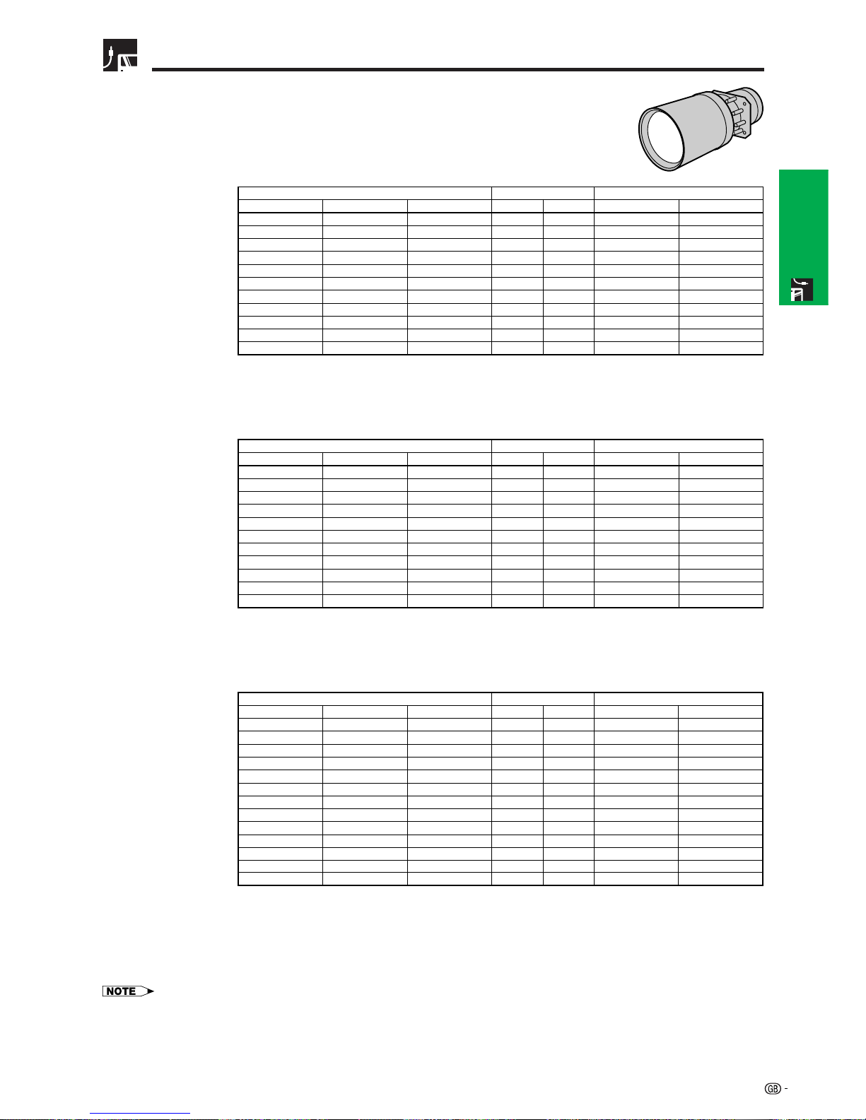
AN-LV40EZ
Throw distance ratio
1.9 to 2.5:1
31.2 m
26.0 m
20.8 m
15.6 m
10.3 m
7.7 m
5.1 m
4.3 m
3.6 m
3.0 m
2.0 m
Screen size (4:3) Projection distance (L)
Maximum
24.0 m
19.9 m
15.9 m
11.9 m
7.9 m
5.9 m
3.9 m
3.3 m
2.8 m
2.3 m
1.5 m
Minimum
457.2 cm
381.0 cm
304.8 cm
228.6 cm
152.4 cm
114.3 cm
76.2 cm
64.0 cm
54.9 cm
45.7 cm
30.5 cm
Lens centre to the lower edge of the screen (H)
Upper
91.4 cm
76.2 cm
61.0 cm
45.7 cm
30.5 cm
22.9 cm
15.2 cm
12.8 cm
11.0 cm
9.1 cm
6.1 cm
Lower
(360)
(300)
(240)
(180)
(120)
(90)
(60)
(50)
(43)
(36)
(24)
914 cm
762 cm
610 cm
457 cm
305 cm
229 cm
152 cm
127 cm
109 cm
91 cm
61 cm
(480)
(400)
(320)
(240)
(160)
(120)
(80)
(67)
(58)
(48)
(32)
1,219 cm
1,016 cm
813 cm
610 cm
406 cm
305 cm
203 cm
170 cm
147 cm
122 cm
81 cm
(600)
(500)
(400)
(300)
(200)
(150)
(100)
(84)
(72)
(60)
(40)
1,524 cm
1,270 cm
1,016 cm
762 cm
508 cm
381 cm
254 cm
213 cm
183 cm
152 cm
102 cm
Diag. Width Height
Computer Input (5:4)
Video Input (4:3)
33.3 m
27.7 m
22.2 m
16.6 m
11.0 m
8.2 m
5.5 m
4.6 m
3.9 m
3.2 m
2.1 m
Screen size (4:3) Projection distance (L)
Maximum
25.6 m
21.3 m
17.0 m
12.7 m
8.5 m
6.3 m
4.2 m
3.5 m
3.0 m
2.5 m
1.6 m
Minimum
457.2 cm
381.0 cm
304.8 cm
228.6 cm
152.4 cm
114.3 cm
76.2 cm
64.0 cm
54.9 cm
45.7 cm
30.5 cm
Lens centre to the lower edge of the screen (H)
Upper
128.0 cm
106.7 cm
85.3 cm
64.0 cm
42.7 cm
32.0 cm
21.3 cm
17.9 cm
15.4 cm
12.8 cm
8.5 cm
Lower
(360)
(300)
(240)
(180)
(120)
(90)
(60)
(50)
(43)
(36)
(24)
914 cm
762 cm
610 cm
457 cm
305 cm
229 cm
152 cm
127 cm
109 cm
91 cm
61 cm
(480)
(400)
(320)
(240)
(160)
(120)
(80)
(67)
(58)
(48)
(32)
1,219 cm
1,016 cm
813 cm
610 cm
406 cm
305 cm
203 cm
170 cm
147 cm
122 cm
81 cm
(600)
(500)
(400)
(300)
(200)
(150)
(100)
(84)
(72)
(60)
(40)
1,524 cm
1,270 cm
1,016 cm
762 cm
508 cm
381 cm
254 cm
213 cm
183 cm
152 cm
102 cm
Diag. Width Height
Video Input (16:9)
• Values with a minus () sign indicate the distance of the lens centre below the bottom of the screen.
(500)
(400)
(300)
(200)
(150)
(133)
(106)
(100)
(92)
(84)
(72)
(60)
(40)
1,270 cm
1,016 cm
762 cm
508 cm
381 cm
338 cm
269 cm
254 cm
234 cm
213 cm
183 cm
152 cm
102 cm
(435)
(348)
(261)
(174)
(131)
(116)
(92)
(87)
(80)
(73)
(63)
(52)
(35)
1,105 cm
884 cm
663 cm
442 cm
333 cm
295 cm
234 cm
221 cm
203 cm
185 cm
160 cm
132 cm
89 cm
(245)
(196)
(147)
(98)
(74)
(65)
(52)
(49)
(45)
(41)
(35)
(29)
(20)
622 cm
498 cm
373 cm
249 cm
188 cm
165 cm
132 cm
124 cm
114 cm
104 cm
89 cm
74 cm
51 cm
Diag. Width
Screen size (4:3)
Height
311.3 cm
249.1 cm
186.8 cm
124.5 cm
93.4 cm
82.8 cm
66.0 cm
62.3 cm
57.3 cm
52.3 cm
44.8 cm
37.4 cm
24.9 cm
Lens centre to the lower edge of the screen (H)
Upper
220.0 cm
176.0 cm
132.0 cm
88.0 cm
66.0 cm
58.5 cm
46.6 cm
44.0 cm
40.5 cm
37.0 cm
31.7 cm
26.4 cm
17.6 cm
Lower
30.2 m
24.2 m
18.1 m
12.0 m
9.0 m
8.0 m
6.3 m
6.0 m
5.5 m
5.0 m
4.3 m
3.5 m
2.3 m
Projection distance (L)
Maximum
23.2 m
18.6 m
13.9 m
9.2 m
6.9 m
6.1 m
4.8 m
4.6 m
4.2 m
3.8 m
3.3 m
2.7 m
1.8 m
Minimum
23
Setup & Connections
Adjusting the Projection Distance
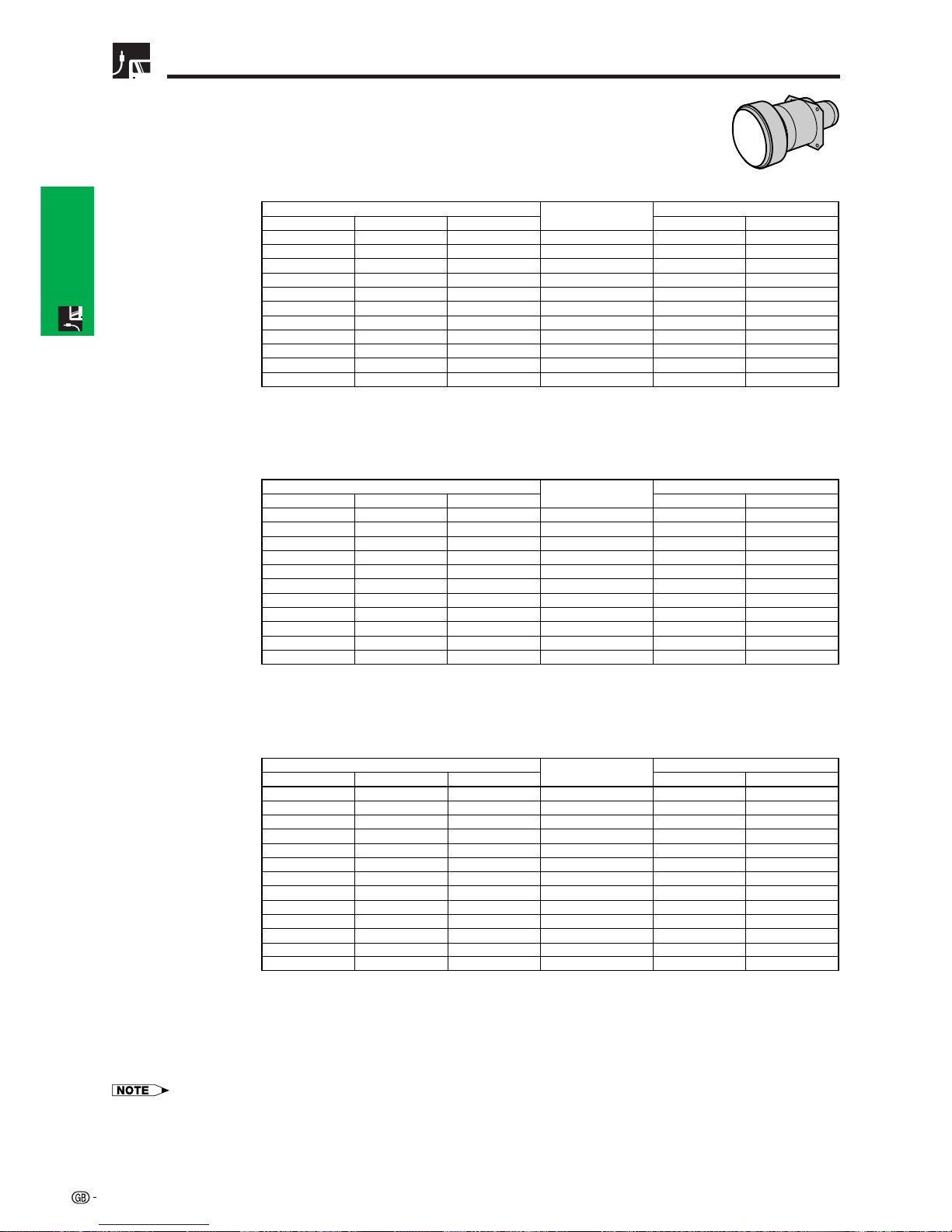
AN-LV18MX
Throw distance ratio
0.9 :1
(360)
(300)
(240)
(180)
(120)
(90)
(60)
(50)
(43)
(36)
(24)
914 cm
762 cm
610 cm
457 cm
305 cm
229 cm
152 cm
127 cm
109 cm
91 cm
61 cm
(480)
(400)
(320)
(240)
(160)
(120)
(80)
(67)
(58)
(48)
(32)
1,219 cm
1,016 cm
813 cm
610 cm
406 cm
305 cm
203 cm
170 cm
147 cm
122 cm
81 cm
(600)
(500)
(400)
(300)
(200)
(150)
(100)
(84)
(72)
(60)
(40)
1,524 cm
1,270 cm
1,016 cm
762 cm
508 cm
381 cm
254 cm
213 cm
183 cm
152 cm
102 cm
10.7 m
8.9 m
7.1 m
5.3 m
3.5 m
2.6 m
1.7 m
1.5 m
1.2 m
1.0 m
0.7 m
Diag. Width
Screen size (4:3)
Height
Projection distance (L)
457.2 cm
381.0 cm
304.8 cm
228.6 cm
152.4 cm
114.3 cm
76.2 cm
64.0 cm
54.9 cm
45.7 cm
30.5 cm
Lens centre to the lower edge of the screen (H)
Upper
411.5 cm
342.9 cm
274.3 cm
205.7 cm
137.2 cm
102.9 cm
68.6 cm
57.6 cm
49.4 cm
41.1 cm
27.4 cm
Lower
(360)
(300)
(240)
(180)
(120)
(90)
(60)
(50)
(43)
(36)
(24)
914 cm
762 cm
610 cm
457 cm
305 cm
229 cm
152 cm
127 cm
109 cm
91 cm
61 cm
(480)
(400)
(320)
(240)
(160)
(120)
(80)
(67)
(58)
(48)
(32)
1,219 cm
1,016 cm
813 cm
610 cm
406 cm
305 cm
203 cm
170 cm
147 cm
122 cm
81 cm
(600)
(500)
(400)
(300)
(200)
(150)
(100)
(84)
(72)
(60)
(40)
1,524 cm
1,270 cm
1,016 cm
762 cm
508 cm
381 cm
254 cm
213 cm
183 cm
152 cm
102 cm
11.4 m
9.5 m
7.6 m
5.7 m
3.8 m
2.8 m
1.9 m
1.6 m
1.3 m
1.1 m
0.7 m
Diag. Width
Screen size (4:3)
Height
Projection distance (L)
457.2 cm
381.0 cm
304.8 cm
228.6 cm
152.4 cm
114.3 cm
76.2 cm
64.0 cm
54.9 cm
45.7 cm
30.5 cm
Lens centre to the lower edge of the screen (H)
Upper
408.4 cm
340.4 cm
272.3 cm
204.2 cm
136.1 cm
102.1 cm
68.1 cm
57.2 cm
49.0 cm
40.8 cm
27.2 cm
Lower
Computer Input (5:4)
Video Input (4:3)
Video Input (16:9)
(500)
(400)
(300)
(200)
(150)
(133)
(106)
(100)
(92)
(84)
(72)
(60)
(40)
1,270 cm
1,016 cm
762 cm
508 cm
381 cm
338 cm
269 cm
254 cm
234 cm
213 cm
183 cm
152 cm
102 cm
(435)
(348)
(261)
(174)
(131)
(116)
(92)
(87)
(80)
(73)
(63)
(52)
(35)
1,105 cm
884 cm
663 cm
442 cm
333 cm
295 cm
234 cm
221 cm
203 cm
185 cm
160 cm
132 cm
89 cm
(245)
(196)
(147)
(98)
(74)
(65)
(52)
(49)
(45)
(41)
(35)
(29)
(20)
622 cm
498 cm
373 cm
249 cm
188 cm
165 cm
132 cm
124 cm
114 cm
104 cm
89 cm
74 cm
51 cm
Diag. Width
Screen size (4:3)
Height
Projection distance (L)
10.3 m
8.3 m
6.2 m
4.1 m
3.1 m
2.7 m
2.1 m
2.0 m
1.9 m
1.7 m
1.4 m
1.2 m
0.8 m
311.3 cm
249.1 cm
186.8 cm
124.5 cm
93.4 cm
82.8 cm
66.0 cm
62.3 cm
57.3 cm
52.3 cm
44.8 cm
37.4 cm
24.9 cm
Lens centre to the lower edge of the screen (H)
Upper
267.0 cm
213.6 cm
160.2 cm
106.8 cm
80.1 cm
71.0 cm
56.6 cm
53.4 cm
49.1 cm
44.9 cm
38.5 cm
32.0 cm
21.4 cm
Lower
• Values with a minus () sign indicate the distance of the lens centre below the bottom of the screen.
24
Setup & Connections
Adjusting the Projection Distance
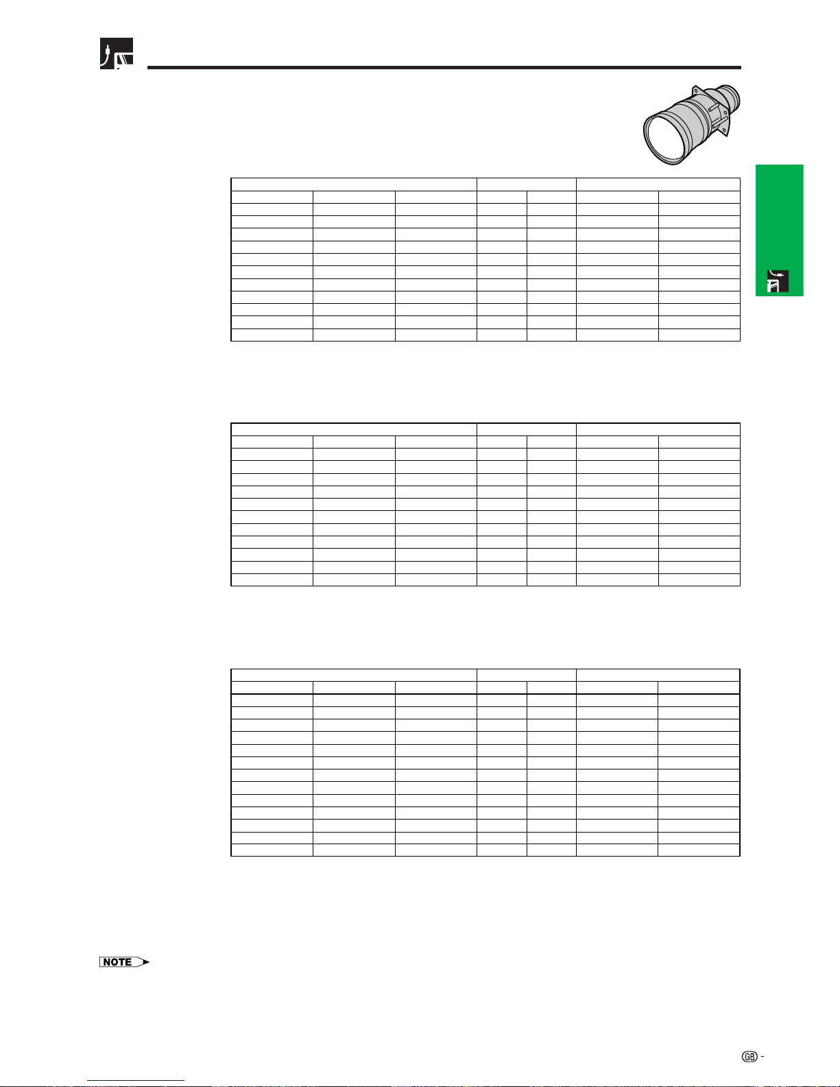
AN-LV26EZ
Throw distance ratio
1.2 to 1.4 :1
17.8 m
14.8 m
11.8 m
8.9 m
5.9 m
4.4 m
2.9 m
2.4 m
2.1 m
1.7 m
1.1 m
Screen size (4:3) Projection distance (L)
Maximum
15.4 m
12.8 m
10.2 m
7.7 m
5.1 m
3.8 m
2.5 m
2.1 m
1.8 m
1.5 m
1.0 m
Minimum
457.2 cm
381.0 cm
304.8 cm
228.6 cm
152.4 cm
114.3 cm
76.2 cm
64.0 cm
54.9 cm
45.7 cm
30.5 cm
Lens centre to the lower edge of the screen (H)
Upper
0.0 cm
0.0 cm
0.0 cm
0.0 cm
0.0 cm
0.0 cm
0.0 cm
0.0 cm
0.0 cm
0.0 cm
0.0 cm
Lower
(360)
(300)
(240)
(180)
(120)
(90)
(60)
(50)
(43)
(36)
(24)
914 cm
762 cm
610 cm
457 cm
305 cm
229 cm
152 cm
127 cm
109 cm
91 cm
61 cm
(480)
(400)
(320)
(240)
(160)
(120)
(80)
(67)
(58)
(48)
(32)
1,219 cm
1,016 cm
813 cm
610 cm
406 cm
305 cm
203 cm
170 cm
147 cm
122 cm
81 cm
(600)
(500)
(400)
(300)
(200)
(150)
(100)
(84)
(72)
(60)
(40)
1,524 cm
1,270 cm
1,016 cm
762 cm
508 cm
381 cm
254 cm
213 cm
183 cm
152 cm
102 cm
Diag. Width Height
19.0 m
15.8 m
12.6 m
9.5 m
6.3 m
4.7 m
3.1 m
2.6 m
2.2 m
1.8 m
1.2 m
Screen size (4:3) Projection distance (L)
Maximum
16.5 m
13.7 m
11.0 m
8.2 m
5.4 m
4.1 m
2.7 m
2.2 m
1.9 m
1.6 m
1.0 m
Minimum
457.2 cm
381.0 cm
304.8 cm
228.6 cm
152.4 cm
114.3 cm
76.2 cm
64.0 cm
54.9 cm
45.7 cm
30.5 cm
Lens centre to the lower edge of the screen (H)
Upper
29.8 cm
24.8 cm
19.8 cm
14.9 cm
9.9 cm
7.4 cm
5.0 cm
4.2 cm
3.6 cm
3.0 cm
2.0 cm
Lower
(360)
(300)
(240)
(180)
(120)
(90)
(60)
(50)
(43)
(36)
(24)
914 cm
762 cm
610 cm
457 cm
305 cm
229 cm
152 cm
127 cm
109 cm
91 cm
61 cm
(480)
(400)
(320)
(240)
(160)
(120)
(80)
(67)
(58)
(48)
(32)
1,219 cm
1,016 cm
813 cm
610 cm
406 cm
305 cm
203 cm
170 cm
147 cm
122 cm
81 cm
(600)
(500)
(400)
(300)
(200)
(150)
(100)
(84)
(72)
(60)
(40)
1,524 cm
1,270 cm
1,016 cm
762 cm
508 cm
381 cm
254 cm
213 cm
183 cm
152 cm
102 cm
Diag. Width Height
Computer Input (5:4)
Video Input (4:3)
Video Input (16:9)
(500)
(400)
(300)
(200)
(150)
(133)
(106)
(100)
(92)
(84)
(72)
(60)
(40)
1,270 cm
1,016 cm
762 cm
508 cm
381 cm
338 cm
269 cm
254 cm
234 cm
213 cm
183 cm
152 cm
102 cm
(435)
(348)
(261)
(174)
(131)
(116)
(92)
(87)
(80)
(73)
(63)
(52)
(35)
1,105 cm
884 cm
663 cm
442 cm
333 cm
295 cm
234 cm
221 cm
203 cm
185 cm
160 cm
132 cm
89 cm
(245)
(196)
(147)
(98)
(74)
(65)
(52)
(49)
(45)
(41)
(35)
(29)
(20)
622 cm
498 cm
373 cm
249 cm
188 cm
165 cm
132 cm
124 cm
114 cm
104 cm
89 cm
74 cm
51 cm
Diag. Width
Screen size (4:3)
Height
311.3 cm
249.1 cm
186.8 cm
124.5 cm
93.4 cm
82.8 cm
66.0 cm
62.3 cm
57.3 cm
52.3 cm
44.8 cm
37.4 cm
24.9 cm
Lens centre to the lower edge of the screen (H)
Upper
131.4 cm
105.2 cm
78.9 cm
52.6 cm
39.4 cm
35.0 cm
27.9 cm
26.3 cm
24.2 cm
22.1 cm
18.9 cm
15.8 cm
10.5 cm
Lower
17.2 m
13.8 m
10.3 m
6.8 m
5.1 m
4.5 m
3.6 m
3.4 m
3.1 m
2.8 m
2.4 m
2.0 m
1.3 m
Projection distance (L)
Maximum
14.9 m
11.9 m
8.9 m
5.9 m
4.4 m
3.9 m
3.1 m
2.9 m
2.7 m
2.4 m
2.1 m
1.7 m
1.1 m
Minimum
• Values with a minus () sign indicate the distance of the lens centre below the bottom of the screen.
25
Setup & Connections
Adjusting the Projection Distance
AN-LV36EZ
Throw distance ratio
1.7 to 2.7 :1
33.9 m
28.3 m
22.6 m
16.9 m
11.2 m
8.4 m
5.5 m
4.6 m
4.0 m
3.3 m
2.1 m
Screen size (4:3) Projection distance (L)
Maximum
21.2 m
17.7 m
14.1 m
10.6 m
7.0 m
5.2 m
3.5 m
2.9 m
2.5 m
2.1 m
1.3 m
Minimum
457.2 cm
381.0 cm
304.8 cm
228.6 cm
152.4 cm
114.3 cm
76.2 cm
64.0 cm
54.9 cm
45.7 cm
30.5 cm
Lens centre to the lower edge of the screen (H)
Upper
0.0 cm
0.0 cm
0.0 cm
0.0 cm
0.0 cm
0.0 cm
0.0 cm
0.0 cm
0.0 cm
0.0 cm
0.0 cm
Lower
(360)
(300)
(240)
(180)
(120)
(90)
(60)
(50)
(43)
(36)
(24)
914 cm
762 cm
610 cm
457 cm
305 cm
229 cm
152 cm
127 cm
109 cm
91 cm
61 cm
(480)
(400)
(320)
(240)
(160)
(120)
(80)
(67)
(58)
(48)
(32)
1,219 cm
1,016 cm
813 cm
610 cm
406 cm
305 cm
203 cm
170 cm
147 cm
122 cm
81 cm
(600)
(500)
(400)
(300)
(200)
(150)
(100)
(84)
(72)
(60)
(40)
1,524 cm
1,270 cm
1,016 cm
762 cm
508 cm
381 cm
254 cm
213 cm
183 cm
152 cm
102 cm
Diag. Width Height
36.2 m
30.1 m
24.1 m
18.0 m
12.0 m
8.9 m
5.9 m
4.9 m
4.2 m
3.5 m
2.3 m
Screen size (4:3) Projection distance (L)
Maximum
22.7 m
18.9 m
15.1 m
11.3 m
7.5 m
5.6 m
3.7 m
3.1 m
2.7 m
2.2 m
1.4 m
Minimum
457.2 cm
381.0 cm
304.8 cm
228.6 cm
152.4 cm
114.3 cm
76.2 cm
64.0 cm
54.9 cm
45.7 cm
30.5 cm
Lens centre to the lower edge of the screen (H)
Upper
29.8 cm
24.8 cm
19.8 cm
14.9 cm
9.9 cm
7.4 cm
5.0 cm
4.2 cm
3.6 cm
3.0 cm
2.0 cm
Lower
(360)
(300)
(240)
(180)
(120)
(90)
(60)
(50)
(43)
(36)
(24)
914 cm
762 cm
610 cm
457 cm
305 cm
229 cm
152 cm
127 cm
109 cm
91 cm
61 cm
(480)
(400)
(320)
(240)
(160)
(120)
(80)
(67)
(58)
(48)
(32)
1,219 cm
1,016 cm
813 cm
610 cm
406 cm
305 cm
203 cm
170 cm
147 cm
122 cm
81 cm
(600)
(500)
(400)
(300)
(200)
(150)
(100)
(84)
(72)
(60)
(40)
1,524 cm
1,270 cm
1,016 cm
762 cm
508 cm
381 cm
254 cm
213 cm
183 cm
152 cm
102 cm
Diag. Width Height
Computer Input (5:4)
Video Input (4:3)
Video Input (16:9)
(500)
(400)
(300)
(200)
(150)
(133)
(106)
(100)
(92)
(84)
(72)
(60)
(40)
1,270 cm
1,016 cm
762 cm
508 cm
381 cm
338 cm
269 cm
254 cm
234 cm
213 cm
183 cm
152 cm
102 cm
(435)
(348)
(261)
(174)
(131)
(116)
(92)
(87)
(80)
(73)
(63)
(52)
(35)
1,105 cm
884 cm
663 cm
442 cm
333 cm
295 cm
234 cm
221 cm
203 cm
185 cm
160 cm
132 cm
89 cm
(245)
(196)
(147)
(98)
(74)
(65)
(52)
(49)
(45)
(41)
(35)
(29)
(20)
622 cm
498 cm
373 cm
249 cm
188 cm
165 cm
132 cm
124 cm
114 cm
104 cm
89 cm
74 cm
51 cm
Diag. Width
Screen size (4:3)
Height
311.3 cm
249.1 cm
186.8 cm
124.5 cm
93.4 cm
82.8 cm
66.0 cm
62.3 cm
57.3 cm
52.3 cm
44.8 cm
37.4 cm
24.9 cm
Lens centre to the lower edge of the screen (H)
Upper
131.4 cm
105.2 cm
78.9 cm
52.6 cm
39.4 cm
35.0 cm
27.9 cm
26.3 cm
24.2 cm
22.1 cm
18.9 cm
15.8 cm
10.5 cm
Lower
32.9 m
26.3 m
19.7 m
13.1 m
9.8 m
8.6 m
6.9 m
6.5 m
5.9 m
5.4 m
4.6 m
3.8 m
2.5 m
Projection distance (L)
Maximum
20.6 m
16.4 m
12.3 m
8.2 m
6.1 m
5.4 m
4.3 m
4.0 m
3.7 m
3.4 m
2.9 m
2.4 m
1.6 m
Minimum
• Values with a minus () sign indicate the distance of the lens centre below the bottom of the screen.
 Loading...