

Page 1
TopPage
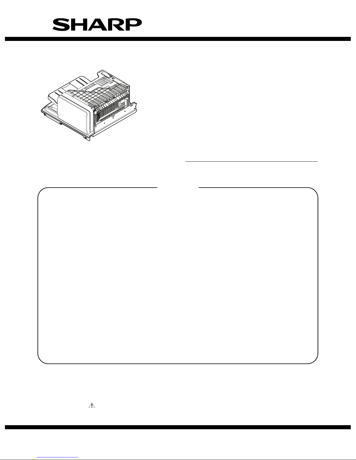
SERVICE MANUAL
CODE: 00ZMXFN23/S1E
DIGITAL MULTIFUNCTIONAL SYSTEM
OPTION
FINISHER
MODEL
CONTENTS
[1] PRODUCT OUTLINE. . . . . . . . . . . . . . . . . . . . . . . . . . . . . . . . . . . . 1-1
[2] SPECIFICTIONS . . . . . . . . . . . . . . . . . . . . . . . . . . . . . . . . . . . . . . . 2-1
[3] EXTERNAL VIEW AND INTERNAL STRUCTURE . . . . . . . . . . . . . 3-1
[4] ADJUSTMENTS . . . . . . . . . . . . . . . . . . . . . . . . . . . . . . . . . . . . . . . 4-1
[5] TROUBLE CODE. . . . . . . . . . . . . . . . . . . . . . . . . . . . . . . . . . . . . . . 5-1
[6] OPERATIONAL DESCRIPTIONS . . . . . . . . . . . . . . . . . . . . . . . . . . 6-1
[7] MAINTENANCE. . . . . . . . . . . . . . . . . . . . . . . . . . . . . . . . . . . . . . . . 7-1
[8] DISASSEMBLY AND ASSEMBLY. . . . . . . . . . . . . . . . . . . . . . . . . . 8-1
[9] SIGNAL LIST . . . . . . . . . . . . . . . . . . . . . . . . . . . . . . . . . . . . . . . . . . 9-1
MX-FN23
[10] ACTUAL WIRING CHART . . . . . . . . . . . . . . . . . . . . . . . . . . . . . . . 10-1
Parts marked with " " are important for maintaining the safety of the set. Be sure to replace these parts with
specified ones for maintaining the safety and performance of the set.
SHARP CORPORATION
This document has been published to be used
for after sales service only.
The contents are subject to change without notice.
Page 2

CONTENTS
[1] PRODUCT OUTLINE . . . . . . . . . . . . . . . . . . . . . . . . . . . . .1-1
[2] SPECIFICTIONS
1. Basic specifications . . . . . . . . . . . . . . . . . . . . . . . . . . . .2-1
[3] EXTERNAL VIEW AND INTERNAL STRUCTURE
1. External and Internal View . . . . . . . . . . . . . . . . . . . . . . . 3-1
2. Detectors and Rollers . . . . . . . . . . . . . . . . . . . . . . . . . . .3-2
3. Motors, Solenoids, Gate, PWB, Switch and Fan . . . . . .3-3
[4] ADJUSTMENTS
1. General. . . . . . . . . . . . . . . . . . . . . . . . . . . . . . . . . . . . . .4-1
2. List of adjustment items . . . . . . . . . . . . . . . . . . . . . . . . . 4-1
3. Details of adjustment and setting . . . . . . . . . . . . . . . . . .4-1
[5] TROUBLE CODE
1. Trouble code list . . . . . . . . . . . . . . . . . . . . . . . . . . . . . . .5-1
2. Details. . . . . . . . . . . . . . . . . . . . . . . . . . . . . . . . . . . . . . .5-1
[6] OPERATIONAL DESCRIPTIONS
1. General . . . . . . . . . . . . . . . . . . . . . . . . . . . . . . . . . . . . . 6-1
2. Outline of the transport path . . . . . . . . . . . . . . . . . . . . . 6-1
3. Offset mode. . . . . . . . . . . . . . . . . . . . . . . . . . . . . . . . . . 6-1
4. Staple mode . . . . . . . . . . . . . . . . . . . . . . . . . . . . . . . . . 6-2
5. Electrical section . . . . . . . . . . . . . . . . . . . . . . . . . . . . . . 6-4
[7] MAINTENANCE
1. Maintenance system table. . . . . . . . . . . . . . . . . . . . . . . 7-1
[8] DISASSEMBLY AND ASSEMBLY
1. External view . . . . . . . . . . . . . . . . . . . . . . . . . . . . . . . . . 8-1
2. Paper entry, alignment, staple. . . . . . . . . . . . . . . . . . . . 8-2
3. Paper delivery . . . . . . . . . . . . . . . . . . . . . . . . . . . . . . . . 8-7
4. Others . . . . . . . . . . . . . . . . . . . . . . . . . . . . . . . . . . . . . . 8-9
5. Fan disassembly . . . . . . . . . . . . . . . . . . . . . . . . . . . . . 8-10
[9] SIGNAL LIST . . . . . . . . . . . . . . . . . . . . . . . . . . . . . . . . . . . 9-1
[10] ACTUAL WIRING CHART . . . . . . . . . . . . . . . . . . . . . . . . 10-1
Page 3
MX-FN23 PRODUCT OUTLINE 1 – 1
[1] PRODUCT OUTLINE
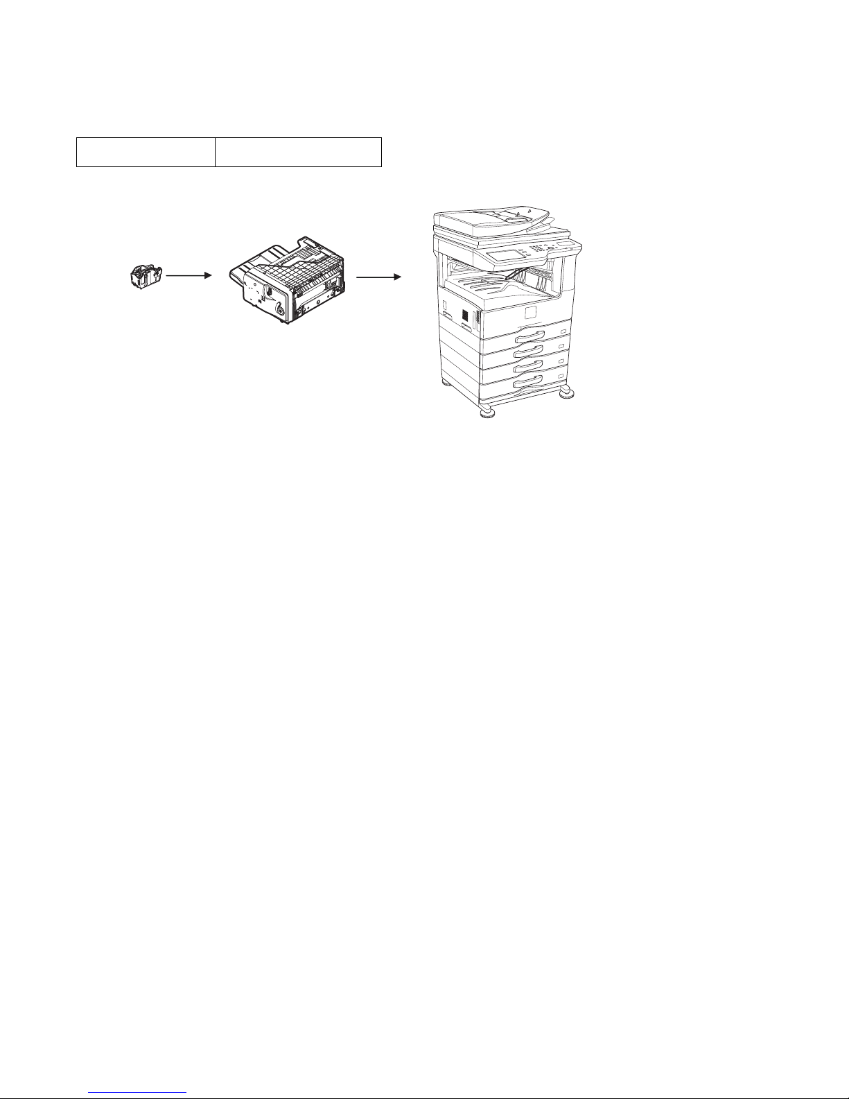
The FN-23 is a post-processing unit of output paper from a copier, a printer, or a fax machine, which is installed to the machine below.
It is provided with the offset function which discharges output paper by shifting copy by copy, and the staple function (only one position stapling).
Since it is installed to the center tray of the machine, there is no extra space for installation.
The finisher needs a staple cartridge as a consumable part. (Staple cartridge (About 5,000 staples x 3 pcs.) MX-SCX1)
Applicable model MX-M264U/M314U/M354U
MX-M264N/M314N/M354N
Finisher
[MX-FN23]
Staple cartridge
Digital multifunctional system
[MX-M264U/M314U/M354U]
[MX-M264N/M314N/M354N]
Page 4

MX-FN23 SPECIFICTIONS 2 – 1
[2] SPECIFICTIONS
1. Basic specifications
(1) Basic specifications
*1: China only
Model name MX-FN23
Name Finisher
Type Built-in type
Paper transport reference Center reference
Loading method Lifting method offset tray
Mode Non-sort offset sort, staple sort
Power consumption About 49W
Power source Supplied from the main unit
Dimensions (W x D x H mm) 472 x 461 x 199mm (When the paper delivery tray is extended: Width 619mm)
Occupying size Conforms to the main unit.
Weight 13.0kg (including the connection unit, excluding the second paper delivery unit.)
Stacker section
Offset quantity 30mm
Stacking
capability
Non-sort Bottom direction (Y) : 25mm or less
Paper exit direction (X) : 25mm or less
Offset Bottom direction (Y) : 25mm or less
Paper exit direction (X) : 25mm or less
Staple alignment (Shift in a job) X,Y : 2.5mm
Paper exit
storage capacity
Non-staple
mode
250 sheets or 35.5mm or less (A3, B4, 11 x 17, 8.5 x 14, 8.5 x 13, 8K*)
500 sheets or 71mm or less (A4, A4R, B5, B5R, 8.5 x 11, 8.5 x 11R, 16K*, 16KR*)
*: 8K, 16K, and 16KR are valid only for China.
100 sheets or 35.5mm or less (A5, A5R, 5.5 x 8.5, 5.5 x 8.5R, B6R, Postcard, OHP, Label sheet, Envelope (20 sheets))
Note: Offset is disabled for Postcard, OHP, Label, Tab paper and Envelope.
Stapling mode 30 section, or 250 sheets, or 35.5mm or less (fixed size paper greater than A4R) (Documents in mixed sizes with the same
width)
30 section, or 500 sheets, or 71mm or less (fixed size paper smaller than A4R)
Note: Stapling heavy paper is only available for front and back cover.
Paper empty detection YES
Paper delivery tray full detection YES
Staple section
Binding position Rear one position binding
Binding quantity 50 sheets (A4, A4R, B5, B5R, 8.5 x 11, 8.5 x 11R, 16K*1, 16KR*1)
30 sheets (A3, B4, 11 x 17, 8.5 x 14, 8.5 x 13, 8K*1)
Mixed load (same width) stapling: 30 sheets
Staple loading method Staple cartridge (5000 staples) (MX-SCX1)
Staple empty detection YES
Manual staple mode NO
Page 5
MX-FN23 SPECIFICTIONS 2 – 2
(2) Usable Paper size/weight
*1: Paper is passed, but alignment is not assured.
*2: Paper is passed and stapling is performed, but alignment is not assured.
*3: For heavy paper of 129g/m
2
or more, alignment is not assured.
*4: Available only for the front cover and the back cover.
*5: Can be output but in not supported.
*6: Comply to "Paper typesetting".
*7: Custom size.
Normal paper exit Offset Staple mode
Paper size 11" x 17" Yes Yes Yes
8.5" x 14" (216 x 356) Yes Yes Yes
8.5" x 13.4" (216 x 340) Yes No No
8.5" x 13" (216 x 330) Yes Yes Yes
8.5" x 11" Yes Yes Yes
8.5" x 11"R Yes Yes Yes
7.25" x 10.5"R Yes*
1
No No
5.5" x 8.5"R Yes*
1
No No
5.5" x 8.5" Yes*
1
Yes *
1
No
A3 Yes Yes Yes
B4 Yes Yes Yes
A4 Yes Yes Yes
A4R Yes Yes Yes
B5 Yes Yes Yes
B5R Yes No Yes
A5R Yes*
1
No No
A5 Yes*
1
Yes *
1
No
B6R Yes*
1
No No
8K Yes Yes Yes
16K Yes Yes Yes
16KR Yes No Yes
A6R Yes*
1
No No
Envelope Commercial10 (4-1/8" x 9-1/2") Yes*
1
No No
International DL (110mm x 220mm) Yes*
1
No No
International C5 (162mm x 229mm) Yes*
1
No No
Extra Yes*
1
No No
Custom*
7
Yes *
1
No No
Paper type Thin paper 56-59g/m
2
Yes *
1
Yes *
1
Yes *
2
Plain paper 60-90g/m
2
Yes Yes Yes
Recycled paper Yes Yes Yes
Heavy paper Max. 200g/m
2
Yes *3 Yes *
3
Yes *
4
Envelope Commercial10 (4-1/8" x 9-1/2") Yes*
1
No No
International DL (110mm x 220mm) Yes*
1
No No
International C5 (162mm x 229mm) Yes*
1
No No
Monarch Yes*
1
No No
OHP Yes*
1
No No
Label sheet (SF-4A3F) Yes*
1
No No
Tab paper Yes*
5
No No
User settings 1-7 Yes*
6
Yes Yes
AB System (mm) Inch Systm (inch)
Min. Max. Min. Max.
Bypass tray
X 140 432 5-1/2 17
Y 100 297 5-1/2 11-5/8
Duplex
X 182 432 8-1/2 17
Y 182 297 7-1/4 11-5/8
Page 6

MX-FN23 EXTERNAL VIEW AND INTERNAL STRUCTURE 3 – 1
DS)Options
[3] EXTERNAL VIEW AND INTERNAL STRUCTURE
1. External and Internal View
No. Name Function/Operation
1 Paper delivery extension tray When making copy or print of a size longer than B5R, pull this section out.
2 Paper delivery tray Copied or printed paper is discharged to this tray.
3 Finisher upper paper guide Only the lead edge section of switch-backed paper is discharged to this section, and then transported to the switch-back
section.
4 Finisher connection lock pawl This pawl locks the finisher to the machine.
By turning the separation lever, this pawl operates to release lock of finisher.
5 Staple cartridge Staples are stored in this cartridge. (Consumable part)
6 Separation lever When replacing a staple cartridge or removing jam paper, turn this lever to the left and slide the whole finisher to the left.
7 JAM cancel knob When a jam occurs in the finisher, turn this knob to remove the jam paper.
1 2 3
47 456
Page 7
MX-FN23 EXTERNAL VIEW AND INTERNAL STRUCTURE 3 – 2
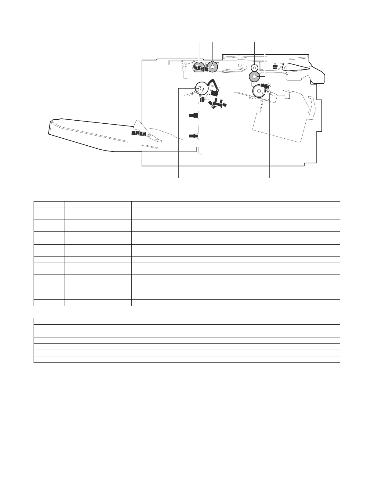
2. Detectors and Rollers
Detectors
Rollers
Signal name Name Type Function/Operation
FAPHPS-F Paper alignment plate home
position sensor F
Transmission type Detects the home position of the paper alignment plate on the front side.
FAPHPS-R Paper alignment plate home
position sensor R
Transmission type Detects the home position of the paper alignment plate on the rear side.
FDRPS Delivery roller position sensor Transmission type Detects that the delivery roller is in the home position.
FDTLLS Delivery tray lower limit sensor Transmission type Detects the lower limit position of the paper delivery tray.
FDTPD Paper delivery tray paper
detector
Paper on the paper delivery tray is detected.
FPLD Paper level detector Transmission type Detects the paper height position of the paper delivery tray (movable section).
FPLS Paper level sensor Reflection type Detects the paper height position of the paper delivery tray (movable section) during a
staple job.
FPPD1 Paper pass detector Reflection type Detects paper entry in the finisher.
FPRD Paper rear edge detector Transmission type Detects that the rear edge of paper transported to the compiler reaches the rear edge of
the compiler.
FSTPD Staple tray paper detector Transmission type Detects paper presence in the staple compiler.
FTPS Delivery tray position sensor Detects the intermediate position of the paper delivery tray.
No. Name Function/Operation
1 Paper delivery roller Discharges paper from the staple compiler to the paper delivery tray.
2 Take-up roller Transports paper which is transported into the staple compiler to the rear edge plate.
3 Paper entry roller (Idle) Applies a pressure to paper and the transport roller to give a transport power of the transport roller to paper.
4 Paper entry roller Transports paper (which is transported from the copier) to the staple compiler.
5 Rear edge take-up roller Drives paper (which is transported to the staple compiler) to the rear edge plate.
6 Paper delivery roller (Idle) Gives a transport power of the transport roller to paper.
FPLD
FPLS
FPPD1
FPRD
FSTPD
FDTPD
FAPHPS-F
FAPHPS-R
FDRPS
12 34
56
FDTLLS
FTPS
Page 8
MX-FN23 EXTERNAL VIEW AND INTERNAL STRUCTURE 3 – 3
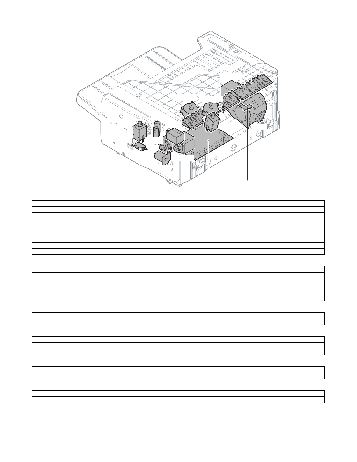
3. Motors, Solenoids, Gate, PWB, Switch and Fan
Motors
Solenoids
Gate
PWB
Switch
Fan
Signal name Name Type Function/Operation
FDRLM Delivery roller lift motor Stepping motor Moves the paper delivery roller up and down.
FPAM-F Paper alignment motor F Stepping motor Drives the paper alignment plate F.
FPAM-R Paper alignment motor R Stepping motor Drives the paper alignment plate R.
FPDM Paper delivery motor Stepping motor Drives the paper delivery roller and the take-up roller. Also moves the take-up roller up
and down.
FPTM Paper transport motor Stepping motor Drives the paper entry roller and the rear edge take-up roller.
FSM Stalpe motor Drives the staple unit.
FTLM Tray lift motor DC brush motor Drives the paper delivery tray (movable section).
Signal name Name Type Function/Operation
FARLS Alignment roller lift
solenoid
Electromagnetic solenoid Controls up-down movement of the rear edge take-up roller.
FPGS Paper gate solenoid Electromagnetic solenoid Drives the select gate of the paper transport path of paper transported to the switch-
back section and paper transported to the paper delivery tray.
FPS Paddle solenoid Electromagnetic solenoid Controls ON/OFF of the paddler rotation.
No. Name Function/Operation
1 Paper entry gate Selects the paper transport path to the switch back section and to the paper delivery tray.
No. Name Function/Operation
2 Control PWB Controls the operation of the finisher.
3 LED PWB Illuminates the staple unit.
No. Name Function/Operation
4 Safety switch Detects open/close of the front cover to turn ON/OFF the motor power.
Signal name Name Type Function/Operation
FCF Finisher cooling fan motor DC brush motor Cools the paper exit motor.
FDRLM
FPAM-F
FPAM-R
FPDM
FPTM
FSM
FTLM
FARLS
FPGS
FPS
FCF
1
24 3
Page 9
MX-FN23 ADJUSTMENTS 4 – 1
[4] ADJUSTMENTS
1. General
Perform an adjustments when a problem occurs.
If the adjustment value is changed when there is no trouble in the
machine, a trouble may be generated such as improper alignment
of paper, paper exit jam, attachment of roller marks on paper, etc.
2. List of adjustment items
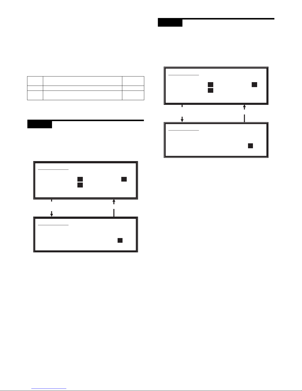
3. Details of adjustment and setting
ADJ 1 Paper alignment width
adjustment
This adjustment is executed when a trouble occurs in paper alignment.
1) Execute Sim3-10.
2) Select "1: FPAM ADJUST".
3) Enter the set value with 10-key. (Press [C] key to clear the
entered values.)
Initial value: 50
When the adjustment value is increased by 1, the alignment
plate F/R width is narrowed by 0.419mm in alignment operation.
When the adjustment value is decreased by 1, the alignment
plate F/R width is widened by 0.419mm in alignment operation.
The alignment plate F and the alignment plate R cannot be
adjusted separately. The shift amount on the F side and that
on the R side are alternatively corrected everytime the adjustment value is increased by 1. (Correction with 51 for the F
side, and 52 for the R side. ... 59 for the F aide, and 60 for the
R side. Similar when the set value is decreased.) When, however, the alignment plate lower cannot be adjusted due to the
mechanism structure, adjust only on the R side without correcting both of the F and the R side.
4) Press [OK] key to save the set value.
5) After completion of the adjustment, make staple copies.
Alignment specification: Within 2.5mm
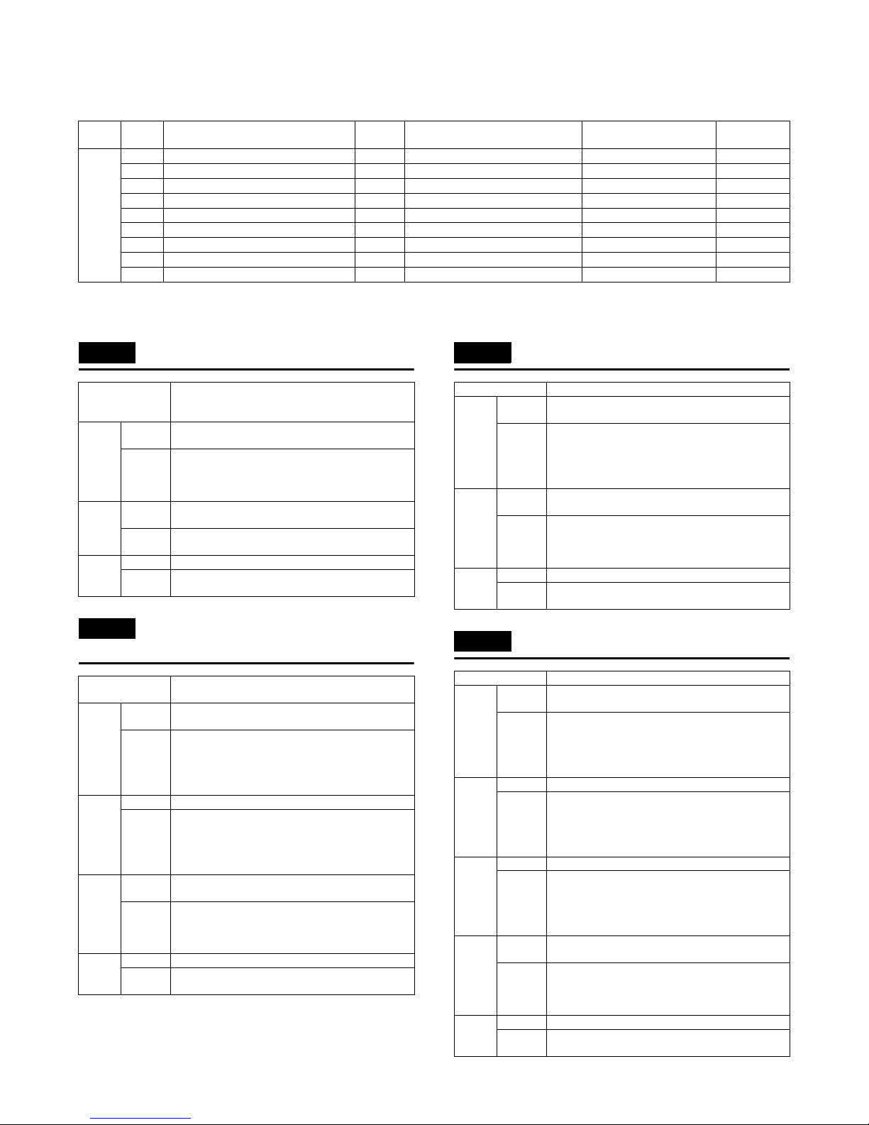
ADJ 2 Paper delivery roller
descending position
adjustment
This adjustment is executed when a paper exit jam occurs or when
roller marks of the paper delivery roller are attached to paper.
1) Execute Sim3-10.
2) Select "2: FDRLM ADJUST".
3) Enter the set value with 10-key. (Press [C] key to clear the
entered values.)
Initial value: 50
When the adjustment value is increased by 1, the shift amount
of the paper delivery roller is changed by 0.13mm toward the
pressure increasing side (*1).
When the adjustment value is decreased by 1, the shift
amount of the paper delivery roller is changed by 0.13mm
toward the pressure decreasing side (*1).
*1: The pressure increasing side means the direction to
increase the paper delivery roller pressure onto paper, and
the pressure decrease side means the direction to
decrease the paper delivery roller pressure onto paper.
4) Press [OK] key to save the set value.
Job No Adjustment items
Simulation
to be used
ADJ1 Paper alignment width adjustment 3-10
ADJ2 Paper delivery roller descending position
adjustment
3-10
SIMULATION 3-10
FINISHER SETTING. SELECT 1-2, AND PRESS START.
1: FPAM ADJUST 50 1
2: FDRLM ADJUST 50
SIMULATION 3-10
FINISHER SETTING. INPUT VALUE 40-60, AND PRESS
START.
1: FPAM ADJUST 50
Select 1 and
press [START] key.
Press [CUSTOM SETTINGS] key.
SIMULATION 3-10
FINISHER SETTING. SELECT 1-2, AND PRESS START.
1: FPAM ADJUST 50 2
2: FDRLM ADJUST 50
SIMULATION 3-10
FINISHER SETTING. INPUT VALUE 40-60, AND PRESS
START.
2: FDRLM ADJUST 50
Select 2 and
press [START] key.
Press [CUSTOM SETTINGS] key.
Page 10
MX-FN23 TROUBLE CODE 5 – 1
[5] TROUBLE CODE
1. Trouble code list
2. Details
F1-00 Finisher communication trouble
F1-03 Finisher delivery roller lift motor
trouble
F1-10 Finisher staple motor trouble
F1-15 Finisher tray lift motor trouble
MAIN
CODE
SUB
CODE
Content Section Operation mode Remedy NOTE
F1 00 Finisher communication trouble FIN When communicating Turn ON/OFF the power.
03 Finisher delivery roller lift motor trouble FIN When the roller is operating Check the connection state.
10 Finisher staple motor trouble FIN When the staple is operating Check the connection state.
15 Finisher tray lift motor trouble FIN When the tray is operating Check the connection state.
19 Finisher paper alignment motor F trouble FIN When the alignment plate is operating Check the connection state.
20 Finisher paper alignment motor R trouble FIN When the alignment plate is operating Check the connection state.
29 Finisher cooling fan trouble FIN When paper is delivered. Check the paper exit, etc.
37 Finisher RAM data trouble FIN When the RAM is accessed. Check the connection state.
50 Finisher incompatible trouble FIN When the power is turned ON Check the connection state.
Phenomenon Communication error with the finisher.
Communication line test error after turning ON the
power or canceling the exclusive simulation.
Case 1 Cause Connection trouble or disconnection of the connector
and the harness.
Check &
Remedy
Check the connector and the harness in the
communication line.
Connect the connector properly. Replace the
harness.
Case 2 Cause Finisher control PWB trouble. Control PWB (PCU)
trouble.
Check &
Remedy
Replace the finisher control PWB or the control PWB
(PCU).
Case 3 Cause Malfunctions caused by noises.
Check &
Remedy
Canceled by turning OFF/ON the power.
Phenomenon Up/down operation trouble of the paper delivery
roller.
Case 1 Cause Connection trouble or disconnection of the connector
and the harness of the motor
Check &
Remedy
Check the connection of the connector and the
harness in the motor line with the finisher control
PWB.
Connect the connector properly. Replace the
harness.
Case 2 Cause Delivery roller position sensor (FDRPS) trouble.
Check &
Remedy
Check to confirm that the FDRPS turns ON/OFF with
SIM3-2.
If it does not turn ON/OFF, check the connection of
the connector and the harness of the sensor.
Replace the sensor.
Case 3 Cause Motor lock, an overcurrent to the motor, intrusion of
foreign material.
Check &
Remedy
Select the FDRLM with SIM3-3 to check the
operation of the single unit.
Check to confirm that there is no foreign material in
the drive system.
Case 4 Cause Finisher control PWB trouble. Motor trouble
Check &
Remedy
Replace the finisher control PWB or the motor.
Phenomenon Staple motor operation trouble
Case 1 Cause Connection trouble or disconnection of the connector
and the harness of the staple unit.
Check &
Remedy
Check the connection of the connector and the
harness between the finisher control PWB and the
staple unit line.
Connect the connector properly. Replace the
harness.
Case 2 Cause Motor lock, an overcurrent to the motor, intrusion of
foreign material.
Check &
Remedy
Select the FSM with SIM3-3 to check the operation of
the single unit.
Check to confirm that there is no foreign material in
the staple unit.
Case 3 Cause Finisher control PWB trouble. Staple unit trouble.
Check &
Remedy
Replace the finisher control PWB or the staple unit.
Phenomenon Up/down operation trouble of the paper delivery tray
Case 1 Cause Connection trouble or disconnection of the connector
and the harness of the motor
Check &
Remedy
Check the connection of the connector and the
harness in the motor line with the finisher control
PWB.
Connect the connector properly. Replace the
harness.
Case 2 Cause Paper level detector (FPLD) trouble.
Check &
Remedy
Check to confirm that the FPLD turns ON/OFF with
SIM3-2.
If it does not turn ON/OFF, check the connection of
the connector and the harness of the sensor.
Replace the sensor.
Case 3 Cause Delivery tray lower limt sensor (FDTLLS) trouble.
Check &
Remedy
Check to confirm that the FDTLLS turns ON/OFF
with SIM3-2.
If it does not turn ON/OFF, check the connection of
the connector and the harness of the sensor.
Replace the sensor.
Case 4 Cause Motor lock, an overcurrent to the motor, intrusion of
foreign material.
Check &
Remedy
Select the FTLM with SIM3-3 to check the operation
of the single unit.
Check to confirm that there is no foreign material in
the drive system.
Case 5 Cause Finisher control PWB trouble. Motor trouble
Check &
Remedy
Replace the finisher control PWB or the motor.
Page 11

MX-FN23 TROUBLE CODE 5 – 2
F1-19 Finisher paper alignment motor F
trouble
F1-20 Finisher paper alignment motor R
trouble
F1-29 Finisher cooling fan trouble
F1-37 Finisher RAM data trouble
F1-50 Finisher incompatible trouble
Phenomenon Operation trouble of the paper alignment plate F
Case 1 Cause Connection trouble or disconnection of the connector
and the harness of the motor
Check &
Remedy
Check the connection of the connector and the
harness in the motor line with the finisher control
PWB.
Connect the connector properly. Replace the
harness.
Case 2 Cause Paper alignment plate home position sensor F
(FAPHPS-F) trouble.
Check &
Remedy
Check to confirm that the FAPHPS-F turns ON/OFF
with SIM3-2.
If it does not turn ON/OFF, check the connection of
the connector and the harness of the sensor.
Replace the sensor.
Case 3 Cause Motor lock, an overcurrent to the motor, intrusion of
foreign material.
Check &
Remedy
Select the FPAM-F with SIM3-3 to check the
operation of the single unit.
Check to confirm that there is no foreign material in
the drive section and the alignment plate.
Case 4 Cause Finisher control PWB trouble. Motor trouble
Check &
Remedy
Replace the finisher control PWB or the motor.
Phenomenon Operation trouble of the paper alignment plate R
Case 1 Cause Connection trouble or disconnection of the connector
and the harness of the motor
Check &
Remedy
Check the connection of the connector and the
harness in the motor line with the finisher control
PWB.
Connect the connector properly. Replace the
harness.
Case 2 Cause Paper alignment plate home position sensor R
(FAPHPS-R) trouble.
Check &
Remedy
Check to confirm that the FAPHPS-R turns ON/OFF
with SIM3-2.
If it does not turn ON/OFF, check the connection of
the connector and the harness of the sensor.
Replace the sensor.
Case 3 Cause Motor lock, an overcurrent to the motor, intrusion of
foreign material.
Check &
Remedy
Select the FPAM-R with SIM3-3 to check the
operation of the single unit.
Check to confirm that there is no foreign material in
the drive section and the alignment plate.
Case 4 Cause Finisher control PWB trouble. Motor trouble
Check &
Remedy
Replace the finisher control PWB or the motor.
Phenomenon When the finisher cooling fan is operating, the lock
signal is not canceled in a certain time.
Case 1 Cause Improper connection or disconnection of the fan
connector and harness.
Check &
Remedy
Check the connector and harness of the finisher
control PWB and the fan line.
Connect the connector securely. Replace the
harness.
Case 2 Cause Motor lock, an over current to the motor, intrusion of
a foreign material.
Check &
Remedy
Select the FCF with SIM03-03 and check the
operation of the single unit.
Case 3 Cause Finisher control PWB trouble, fan trouble.
Check &
Remedy
Replace the finisher control PWB or the staple unit.
Phenomenon Backup RAM operation trouble
Case 1 Cause Finisher control PWB trouble. EEPROM trouble.
Check &
Remedy
Replace the finisher control PWB or the EEPROM.
Phenomenon Connection of a finisher incompatible with the
machine is detected.
Case 1 Cause Connection of a finisher incompatible with the
machine is detected.
Check &
Remedy
Connect the MX-FN23 to the machine.
Page 12

MX-FN23 OPERATIONAL DESCRIPTIONS 6 – 1
[6] OPERATIONAL DESCRIPTIONS
1. General
This chapter describes the operations of the finisher.
The major operation modes are as follows:
• Offset mode
• Staple mode
In this chapter, the basic operations in the above two modes are described.
2. Outline of the transport path
The outline of the transport path is described below.
3. Offset mode
When the operation mode command is received from the copier,
the finisher starts the transport operation.
A. Reception of paper discharged from the main
unit
1) The paper delivery motor (FPDM) is driven in the paper delivery direction to lift the take-up roller. When a flapper solenoid
request (finisher paper pass) is received, the paper gate solenoid (FPGS) is turned ON to switch the paper pass gate to the
finisher side.
2) When paper enters the finisher, the paper transport motor
(FPTM) is driven at the machine paper delivery speed to
receive paper delivery from the machine.
3) When the rear edge of paper passes the paper delivery roller
of the machine, the paper transport motor (FPTM) is accelerated to 400mm/sec. After a lapse of a certain time, the paper
alignment motor F (FPAM-F) and the paper alignment motor R
(FPAM-R) are driven to make the paper alignment plate stand
by outside of paper. Then, the alignment roller lift solenoid
(FARLS) is turned ON to lift the rear edge take-up roller.
No. Name No. Name
1 Delivery movable tray 8 Paper pass detector
2 Paper delivery tray paper detector 9 Paper pass gate
3 Delivery paddler 10 Stapler
4 Paper delivery roller 11 Rear edge plate
5 Take-up roller 12 Paper rear edge detector
6 Paper alignment plate (F, R) 13 Rear edge take-up roller
7 Paper pass roller 14 Paper level actuator
45 7
10
31 6
11121314
2 8 9
Page 13

MX-FN23 OPERATIONAL DESCRIPTIONS 6 – 2
B. Paper alignment
1) When the rear edge of paper passes the paper pass roller, the
paper delivery motor (FPDM) is driven in the reversing direction at 400mm/sec, descending and rotating the take-up roller
to pull the paper rear edge to the rear edge plate.
2) After a lapse of time from detecting ON of the paper rear edge
detector (FPRD), the paper delivery motor (FPDM) is driven in
the paper delivery direction at 400mm/sec, lifting the take-up
roller and rotating the paper delivery roller. At the same time,
the delivery roller lift motor (FDRLM) is driven downward to
shift to the stand-by position of the paper delivery roller.
3) After the take-up roller is lifted, the paper alignment motor F
(FPAM-F) and the paper alignment motor R (FPAM-R) are
driven by a certain level to align paper to the front side or to the
rear side.
C. Paper delivery
1) After completion of alignment, the delivery roller lift motor
(FDRLM) is driven downward to lower the paper delivery roller
to the paper delivery position, discharging paper in the process
tray.
2) After detecting OFF of the paper rear edge detector (FPRD),
the paddle solenoid (FPS) is turned ON to shift to the delivery
paddler to the save position.
3) After a lapse of time from detecting OFF of the paper rear
edge detector (FPRD), the paper delivery motor (FPDM) is
decelerated to decelerate paper delivery. At the same time, the
paper alignment motor F (FPAM-F) and the paper alignment
motor R (FPAM-R) are driven to shift the paper alignment plate
to the home position.
The alignment roller lift solenoid (FARLS) is turned OFF to
descend the rear edge take-up roller.
4) After the paper passes the paper delivery roller, the delivery
roller lift motor (FDRLM) is driven upward to lift the paper delivery roller to the home position.
5) After lifting the paper delivery roller, the paddle solenoid (FPS)
is turned OFF to rotate the paper delivery paddler one turn and
to press paper with the paper level actuator.
6) When there is the next paper, repeat the procedures from "A-
2)". In the same bundle, however, the alignment direction of
the paper alignment plate is the same. When the bundle is
changed, the alignment position is changed to the opposite to
that of the previous bundle.
7) If there is no paper following, each actuator is turned OFF to
complete the transport operations.
4. Staple mode
When the operation mode command is received from the copier,
the finisher starts the transport operation.
A. Reception of paper discharged from the main
unit
1) The paper delivery motor (FPDM) is driven in the paper delivery direction to lift the take-up roller. When a flapper solenoid
request (finisher paper pass) is received, the paper gate solenoid (FPGS) is turned ON to switch the paper pass gate to the
finisher side.
2) When paper enters the finisher, the paper transport motor
(FPTM) is driven at the machine paper delivery speed to
receive paper delivery from the machine.
3) When the rear edge of paper passes the paper delivery roller
of the machine, the paper transport motor (FPTM) is accelerated to 400mm/sec. After a lapse of a certain time, the paper
alignment motor F (FPAM-F) and the paper alignment motor R
(FPAM-R) are driven to make the paper alignment plate stand
by outside of paper.
Page 14

MX-FN23 OPERATIONAL DESCRIPTIONS 6 – 3
B. Paper alignment and stapling
1) When the rear edge of paper passes the paper pass roller, the
paper delivery motor (FPDM) is driven in the reversing direction at 400mm/sec, descending and rotating the take-up roller
to pull the paper rear edge to the rear edge plate.
2) After a lapse of time from detecting ON of the paper rear edge
detector (FPRD), the paper delivery motor (FPDM) is driven in
the paper delivery direction at 400mm/sec, lifting the take-up
roller and rotating the paper delivery roller.
3) After a lapse of a certain time from detecting ON of the paper
rear edge detector (FPRD), the paper alignment motor F
(FPAM-F) or the paper alignment motor R (FPAM-R) is driven
by a certain level depending on the paper to be aligned to align
paper to the staple position.
4) After completion of alignment, the alignment roller lift solenoid
(FARLS) is turned OFF to descend the rear edge take-up
roller. If two or more sheets of paper are aligned, the alignment
motor operated in procedure 3) to shift the paper alignment
plate to the home position. The operations from [A-2] are
repeated for the specified number of sheets. After completion
of alignment of the specified number of sheets, the staple
motor (FSM) is driven to perform stapling.
C. Paper delivery
1) After stapling, the paper alignment motor R (FPAM-R) and the
paper alignment motor F (FPAM-F) are driven to separate the
paper alignment plate 3mm away from paper. At the same
time, the delivery roller lift motor (FDRLM) is driven downward
by a certain level to shift the paper delivery roller to the paper
delivery position, discharging the paper bundle from the process tray.
2) After detecting OFF of the paper rear edge detector (FPRD),
the paddle solenoid (FPS) is turned ON to shift to the delivery
paddler to the save position.
3) After a lapse of time from detecting OFF of the paper rear
edge detector (FPRD), the paper delivery motor (FPDM) is
decelerated to decelerate paper delivery. At the same time, the
paper alignment motor F (FPAM-F) and the paper alignment
motor R (FPAM-R) are driven to shift the paper alignment plate
to the home position.
The alignment roller lift solenoid (FARLS) is turned OFF to
descend the rear edge take-up roller.
4) After the paper passes the paper delivery roller, the delivery
roller lift motor (FDRLM) is driven upward to lift the delivery
roller to the home position.
5) After lifting the paper delivery roller, the paddle solenoid (FPS)
is turned OFF to rotate the paper delivery paddler one turn and
to press paper with the paper level actuator.
6) When there is the next paper, repeat the procedures from "A-
2)".
7) If there is no paper following, each actuator is turned OFF to
complete the transport operations.
Page 15

MX-FN23 OPERATIONAL DESCRIPTIONS 6 – 4
5. Electrical section
A. Overall block diagram
CPU
)
7
13
2/S
8
H(
(STA457C)
(2SB1240 x4)
+24V
+24V
+24V
P-GND
FG
WSSF
FAPHPS-R
FPRD
FAPHPS-F
FSTPD
FDTLLS
FPLD
FDRPS
+5V
+5V
+5V
+5V
+5V
+5V
+5V
+5V
+5V
+5V
+5VR
FTPS
FPPD1
S-GND
MX-FN23
FDTPD
FPLS
+24VR
+24VR
+24V
Paper alignment motor F
Delivery roller lift motor
Paper delivery motor
Paper transport motor
Paper alignment motor R
H bridge circuit
Tray lift motor
Paddle solenoid
Paper gate solenoid
Alignment roller lift solenoid
Transistor array
Fan motor drive circuit
Not installed
LED PWB UN
Illumination of the staple unit
Cooling fan motor
RxD-FIN
+3.3V+5V
+24V
+24VR
TxD-FIN
DSR-FIN
/DTR-FIN
/RES-FIN
FINDET
Input buffer
Input buffer
Output buffer
Output buffer
Input buffer
3-terminal Reg
Input buffer
Safety switch
On-board
writing circuit
Main unit
FPAPD
FDRLPD
FPDPD
FPTPD
STLK
FCF-LD
FSL
FPAM-F
FPAM-R
FDRLM
FPDM
FPTM
FSM
FSHPS
FSED
FSLD
FTLM
FPGS
FPS
FARL S
FCF
FSL
+24V
+24V
+24VR
+24VR
+5V
+24VR
+5VR
(TD62003APG)
Paper rear edge detector
Paper alignment plate home
position sensor F
Staple tray paper detector
Paper level detector
Delivery tray lower limit sensor
Delivery tray position sensor
Paper pass detector
Delivery roller position sensor
Paper alignment plate home
position sensor R
Paper delivery tray paper detector
Paper level sensor
IF MAIN PWB UN
Sensor
in put
circuit
Chopping
circuit
(STA7101M)
Chopping
circuit
(STA7101M)
Chopping
circuit
(STA7101M)
Chopping
circuit
(STA7101M)
(STA7101M)
Chopping
circuit
H bridge circuit
Staple Motor
Staple home position sensor
Staple empty detector
Staple lead detector
Staple unit
(RQJ0602EGDQS)
Page 16

MX-FN23 MAINTENANCE 7 – 1
[7] MAINTENANCE
1. Maintenance system table
5: Check {: Clean s: Replace U: Adjust I: Lubricate
No. Part name 75K 150K 225K 300K 375K 450K 525K 600K Remark
1 Rear edge take-up roller 55555555Replace as needed.
Supply of service parts
2 Staple cartridge Replace at every 5K. Replacement is made by the user.
1
2
Page 17

MX-FN23 DISASSEMBLY AND ASSEMBLY 8 – 1
[8] DISASSEMBLY AND
ASSEMBLY
1. External view
A. Finisher
1) Remove the hand screw from the finisher connection connector on the side of the machine, and remove the machine connection harness from the finisher.
2) Open the front cover. Remove the resin clip, and remove the
front cover.
3) Remove the screw, and remove the left cabinet of the
machine.
4) Open the front cabinet of the machine.
5) Remove the screw, and remove the front cabinet lower and the
connection cabinet.
6) Release the lock with the separation lever, and slide the finisher to the left.
7) Remove the connection plate, and slide the finisher toward
you.
8) Remove the finisher.
Page 18

MX-FN23 DISASSEMBLY AND ASSEMBLY 8 – 2
B. Main PWB cover
1) Remove the screw, and remove the main PWB cover.
C. Front cabinet
1) Remove the screw, and remove the separation lever. Remove
the screw, and remove the front cabinet.
D. Rear cabinet
1) Remove the screw, and remove the rear cabinet.
E. Paper entry paper guide unit
1) Remove the screw, and remove the paper entry paper guide
unit.
F. Upper paper guide
1) Remove the screw, and remove the upper paper guide.
2. Paper entry, alignment, staple
A. Staple cartridge
1) Open the front cover.
2) Turn the separation lever to the left to separate the finisher
from the machine.
3) Pull the lever of the staple case to remove the staple case.
NOTE: When installing the staple case, push it until it locks.
Page 19

MX-FN23 DISASSEMBLY AND ASSEMBLY 8 – 3
4) Remove the staple cartridge.
NOTE: When installing the staple cartridge, push it until it locks.
NOTE: If there is any staple remaining in the staple cartridge, the
cartridge cannot be removed.
B. Staple motor
1) Remove the main PWB cover.
2) Disconnect the connector, remove the screw, and remove the
staple motor.
C. Paper gate solenoid
1) Remove the front cabinet.
2) Disconnect the connector, remove the screw, and remove the
paper gate solenoid mounting plate unit.
3) Remove the screw, and remove the paper gate solenoid.
NOTE: After fixing the paper gate solenoid, the plunger must be in
contact with the molt (F/R) of the paper entry lower PG in
the free state.
Press the plunger with your finger to check to confirm that it
is in contact with the molt (F/R) of the paper entry upper
PG.
D. Safety switch
1) Disconnect the connector, remove the screw, and remove the
safety switch.
E. Paper pass detector
1) Remove the paper entry paper guide unit.
2) Remove the upper paper guide.
3) Remove the screw, remove the mounting plate, and disconnect the connector. Remove the screw, and remove the paper
entry detector.
Page 20

MX-FN23 DISASSEMBLY AND ASSEMBLY 8 – 4
F. Paper rear edge detector
1) Disconnect the connector, remove the screw, and remove the
upper stay right unit.
2) Remove the screw, and remove the ST paper entry paper
guide lower.
3) Remove the paper rear edge detector, and disconnect the connector.
G. Paper transport motor
1) Disconnect the connector, remove the screw, and remove the
harness holder.
2) Disconnect the connector, remove the screw, and remove the
paper transport motor.
H. Rear edge take-up roller
1) Remove the E-ring, the pulley, the belt, and the parallel pin.
2) Disconnect the connector, remove the screw, and remove the
take-up solenoid mounting plate unit.
Page 21

MX-FN23 DISASSEMBLY AND ASSEMBLY 8 – 5
3) Remove the E-ring, the tray paper entry collar, and the parallel
pin, and remove the rear edge take-up roller.
I. Alignment roller lift solenoid
1) Disconnect the connector, remove the screw, and remove the
roller lift solenoid.
NOTE: After fixing the roller lift solenoid, the plunger must be in
contact with the rear edge regulation plate in the free state.
Press the plunger with your finger to check to confirm that
the clearance between the take-up roller and the rear edge
regulation plate is 10 - 12mm.
J. Paper alignment motor F
1) Remove the JAM release knob, the one-way coupling, the
Mylar, the pulley, the SP pin, the E-ring, and the bearing, and
remove the paper entry roller.
2) Remove the screw, and remove the upper stay left.
3) Remove the E-ring, and remove the pressure release drive
gear. Remove the E-ring, and slide the bearing, and remove
the paper delivery pressure release PG unit.
4) Remove the E-ring, the Mylar, the pulley, and the parallel pin.
Remove the E-ring, and slide the bearing, and remove the
paper delivery roller unit.
5) Disconnect the connector. Remove the screw, and remove the
compiler.
10 12mm0mm
Page 22

MX-FN23 DISASSEMBLY AND ASSEMBLY 8 – 6
6) Disconnect the connector. Remove the screw, and remove the
paper alignment motor F.
K. Paper alignment motor R
1) Disconnect the connector. Remove the screw, and remove the
paper alignment motor R.
L. Paper alignment plate home position sensor F
1) Remove the screw, remove the mounting plate, and disconnect the connector. Remove the paper alignment plate home
position F sensor from the mounting plate.
M. Paper alignment plate home position sensor R
1) Remove the screw, remove the mounting plate, and disconnect the connector. Remove the paper alignment plate home
position R sensor from the mounting plate.
N. Staple tray paper detector
1) Remove the screw, and remove the sensor holder and the rear
edge regulation plate.
2) Remove the screw, and remove the jogger F and the jogger R.
3) Remove the screw, and remove the alignment tray upper unit.
Page 23

MX-FN23 DISASSEMBLY AND ASSEMBLY 8 – 7
4) Remove the staple tray paper detector, and disconnect the
connector.
3. Paper delivery
A. Delivery roller position sensor
1) Remove the rear cabinet.
2) Remove the E-ring, and remove the pressure release drive
gear. Disconnect the connector, and remove the paper delivery roller position sensor.
B. Tray lift motor
1) Remove the front cabinet.
2) Remove the harness holder.
3) Disconnect the connector, remove the screw, and remove the
lift drive frame.
4) Remove the worm gear and the screw, and remove the tray lift
motor.
C. Paddle solenoid
1) Remove the E-ring, the paddler drive collar, the baring, the
gear, the parallel pin, the Mylar, the belt, and the pulley.
2) Remove the screw, and remove the EV frame unit.
3) Remove the screw, and remove the paddle solenoid.
Page 24

MX-FN23 DISASSEMBLY AND ASSEMBLY 8 – 8
NOTE: After fixing the paddle solenoid, the paddler solenoid arm
must be in contact with the paddler drive collar with the
plunger in the free state.
Press the plunger with your finger to check to confirm that
the clearance between the paddler solenoid arm and the
paddler drive collar is 0 - 1.5mm.
D. Delivery tray position sensor, Delivery tray
lower limit sensor
1) Remove the delivery tray position sensor and the delivery tray
lower limit sensor.
E. Paper delivery motor
1) Remove the compiler.
2) Remove the spring, the E-ring, the gear, and remove the
screw.
3) Disconnect the connector, remove the paper delivery motor
unit.
4) Remove the screw, and remove the paper delivery motor.
F. Delivery roller lift motor
1) Remove the screw, and remove the pressure release drive
cover. Remove the screw.
2) Disconnect the connector, and remove the delivery roller lift
motor.
0 - 1.5mm0mm
Page 25

MX-FN23 DISASSEMBLY AND ASSEMBLY 8 – 9
G. Paper level detector
1) Disconnect the connector, remove the paper level detector.
H. Paper level sensor
1) Disconnect the connector. Remove the screw, and remove the
paper level sensor.
I. Paper delivery tray paper detector
1) Remove the screw, and remove the tray upper cover.
2) Remove the paper delivery extension tray.
3) Remove the actuator. Remove the paper delivery tray paper
detector, and disconnect the connector.
4. Others
A. LED PWB
1) Remove the main PWB cover.
2) Remove the front cabinet.
3) Remove the paper entry paper guide unit.
4) Disconnect the connector, remove the screw, and remove the
LED cover. Remove the screw, and remove the LED PWB.
B. Main PWB
1) Remove the compiler.
2) Disconnect the connector, remove the screw, and remove the
main PWB.
Page 26

MX-FN23 DISASSEMBLY AND ASSEMBLY 8 – 10
5. Fan disassembly
1) Remove one screw from the bottom frame.
2) Disconnect the connector of the FAN.
3) Remove the FAN together with the mounting plate.
4) Remove two screws from the FAN mounting plate.
Page 27

MX-FN23 SIGNAL LIST 9 – 1
[9] SIGNAL LIST
Signal
name
Name Function/Operation
Connector level
Connector
No.
Pin
No.
NOTE
"L" "H"
FAPHPS-F Finisher paper alignment plate
home position sensor F
Detects the standby position (HP) of
the alignment plate F.
Other than
HP
HP CNF 17
FAPHPS-RFinisher paper alignment plate
home position sensor R
Detects the standby position (HP) of
the alignment plate R.
Other than
HP
HP CNF 18
FARLS Finisher alignment roller lift
solenoid
Up/down operation of the take-up
roller
Up Down CNF 13
FDRLM Finisher delivery roller lift motor Up/down operation of the delivery
roller
– – CNC 12-17
FDRLMA Finisher delivery roller lift motor
control signal (phase A)
Controls the delivery roller lift motor
(phase A).
– – CNC 15
FDRLM/A Finisher delivery roller lift motor
control signal (phase /A)
Controls the delivery roller lift motor
(phase /A).
– – CNC 13
FDRLMB Finisher delivery roller lift motor
control signal (phase B)
Controls the delivery roller lift motor
(phase B).
– – CNC 12
FDRLM/B Finisher delivery roller lift motor
control signal (phase /B)
Controls the delivery roller lift motor
(phase /B).
– – CNC 14
FDRPS Finisher delivery roller position
sensor
Detects the delivery roller position. Upper
limit
Other than
upper limit
CNC 18
FDTLLS Finisher delivery tray lower limit
sensor
Detects the lower limit position of the
paper delivery tray.
Other than
lower limit
Lower limit CND 25
FDTPD Paper delivery tray paper detector Paper on the paper delivery tray is
detected.
Paper
present
on the tray
Paper empty
on the tray
CNC 22
FPAM-F Finisher paper alignment motor F Operates the alignment plate F side. – – CNF 1-6
FPAM-FA Finisher paper alignment motor F
control signal (phase A)
Controls the alignment motor F.
(phase A)
– – CNF 4
FPAM-F/A Finisher paper alignment motor F
control signal (phase /A)
Controls the alignment motor F.
(phase /A)
– – CNF 2
FPAM-FB Finisher paper alignment motor F
control signal (phase B)
Controls the alignment motor F.
(phase B)
– – CNF 1
FPAM-F/B Finisher paper alignment motor F
control signal (phase /B)
Controls the alignment motor F.
(phase /B)
– – CNF 3
FPAM-R Finisher paper alignment motor R Operates the alignment plate R side. – – CNF 7-12
FPAM-RA Finisher paper alignment motor R
control signal (phase A)
Controls the alignment motor R.
(phase A)
– – CNF 10
FPAM-R/A Finisher paper alignment motor R
control signal (phase /A)
Controls the alignment motor R.
(phase /A)
– – CNF 8
FPAM-RB Finisher paper alignment motor R
control signal (phase B)
Controls the alignment motor R.
(phase B)
– – CNF 7
FPAM-R/B Finisher paper alignment motor R
control signal (phase /B)
Controls the alignment motor R.
(phase /B)
– – CNF 9
FPDM Finisher paper delivery motor Takes up and discharges paper on
the compiler tray.
– – CND 1-6
FPDMA Finisher paper delivery motor
control signal (phase A)
Controls the paper delivery motor
(phase A).
– – CND 4
FPDM/A Finisher paper delivery motor
control signal (phase /A)
Controls the paper delivery motor
(phase /A).
– – CND 2
FPDMB Finisher paper delivery motor
control signal (phase B)
Controls the paper delivery motor
(phase B).
– – CND 1
FPDM/B Finisher paper delivery motor
control signal (phase /B)
Controls the paper delivery motor
(phase /B).
– – CND 3
FPGS Finisher paper pass gate solenoid Selects the transport path of
reversed paper and discharged
paper from the main unit.
Reverse
path
Exit path
(To FIN side)
CND 20
FPLD Finisher paper level detector Detects the paper surface on the
paper delivery tray.
– Paper surface
detection
CNC 25
FPLS Finisher paper level sensor Detects the paper surface on the
paper delivery tray.
Paper
surface
detection
–CNA5
FPPD1 Finisher paper pass detector Detects paper which enters FIN. Paper
present
Paper empty CND 29
FPRD Finisher paper rear edge detector Detects the paper rear edge at the
center when taking paper into the
compiler tray.
Paper
present
Paper empty CNF 22
FPS Finisher paddle solenoid Rotates the paddler. – – CND 18 Rotates one turn
by ON–OFF.
FPTM Finisher paper transport motor Transports paper discharged from
the main unit.
– – CND 7-12
Page 28

MX-FN23 SIGNAL LIST 9 – 2
FPTMA Finisher paper transport motor
control signal (phase A)
Controls the transport motor
(phase A).
– – CND 10
FPTM/A Finisher paper transport motor
control signal (phase /A)
Controls the transport motor
(phase /A).
– – CND 8
FPTMB Finisher paper transport motor
control signal (phase B)
Controls the transport motor
(phase B).
– – CND 7
FPTM/B Finisher paper transport motor
control signal (phase /B)
Controls the transport motor
(phase /B).
– – CND 9
FCF Finisher cooling fan Cools the paper exit motor. OFF ON CND 15
FSED Finisher staple empty detector Detects empty of spare staples in
the stapler.
Staple
present
Staple empty CNC 10
FSHPS Finisher staple home position
sensor
Detects the standby position of the
stapler.
HP Out of home
position
CNC 8
FSLD Finisher staple lead detector Detects the staple position of the
stapler.
Ready Other than
Ready
CNC 9
FSM Finisher staple motor Stapling operation of paper bundle – – CNC 3-6
FSM+ Finisher staple motor control
signal (+ side)
Controls the staple motor (+ side). – – CNC 3, 4
FSM- Finisher staple motor control
signal (- side)
Controls the staple motor (- side). – – CNC 5, 6
FSSW Finisher safety switch Turns OFF the power when the front
door is opened to stop the motor.
––CNE1-2
FSTPD Finisher staple tray paper
detector
Detects paper empty on the
compiler tray.
Paper
empty
Paper present CNF 24-26
FTLM Finisher tray lift motor Up/down operation of the paper
delivery tray
– – CNF 13-14
FTLM+ Finisher tray lift motor control
signal (+)
Controls the tray lift motor (+ side). – – CND 13
FTLM- Finisher tray lift motor control
signal (-)
Controls the tray lift motor (- side). – – CND 14
FTPS Finisher delivery tray position
sensor
Detects the upper limit position of
the paper delivery tray.
Other than
upper limit
Upper limit CND 24
Signal
name
Name Function/Operation
Connector level
Connector
No.
Pin
No.
NOTE
"L" "H"
Page 29

MX-FN23 ACTUAL WIRING CHART 10 – 1
[10] ACTUAL WIRING CHART
CN-D
B30B-PHDSS-B
FPDMA
2187564910
31246
5
PHR-6
873154612
+5V
P-GND
+24V
CN-A
B09B-PASK-1
FINSTS
FINCMD
/FINCRDY
/FINSRDY
/RES-FIN
FPLS
S-GND
CN-B
B3P-VH
FTLM
FTLM+
Tray lift motor
Cooling fan motor
PHR-2
FTLM-
Safety switch
1
3
RES-FIN/
2
4
FWE
P31(TXD1)
CN-J
B12B-PH-K-S
765
+3.3V8MD2
+3.3V
11910
12
S-GND
P33(RXD1)
P35(SCLK1)
RES-FIN
S-GND
+5V
19
11121517181314162029222125232827262430
3
FPDM/A
FPDMB
FPDM/B
+24VR
+24VR
FPTMA
FPTM/A
FPTMB
FPTM/B
+24VR
+24VR
FLTM+
FTLM-
FCF
FPGS/
+24V
+5V
+5V
FTPS
FDTLLS
S-GND
S-GND
S-GND
FPPD1
Main unit
FPDMA
+24VR
FPDM/B
FPDMB
FPDM/A
+24VR
FPDM
Delivery roller lift motor
FPTM/B
+24VR
FPTMA
FPTM/A
FPTMB
+24VR
31264
PHR-6
5
FPTM
Paper transport motor
2
1
Paddle solenoid
FPAM-F/B
+24V
FPAM-FA
FPAM-F/A
FPAM-FB
+24V
12543
6
FPAM-F
Paper alignment motor F
SMR-06V-B SMP-06V-BC
FPAM-RA
+24V
FPAM-R/B
FPAM-RB
FPAM-R/A
+24V
12456
3
FPAM-R
Paper alignment motor R
SMP-06V-BCSMR-06V-B
SMR-03V-N SMP-03V-NC
+24V
3
1
lignment roller lift solenoid
FARLS/
FARLS
1
FAPHPS-F
FAPHPS-F
2
Paper alignment plate
home position sensor F
S-GND
PHR-3
3+5V
FAPHPS-R
1
FAPHPS-R
S-GND
2
PHR-3
3+5V
1
FPRD
S-GND
FPRD 2
179228-3
+5V3S-GND
1
2
FSTPD
Staple tray paper detector
PHR-3
FSTPD
+5VR
3
Paper rear edge detector
FPS-187
FPS-187
1 FSSW
1 +24V(OUT)
FSSW
+24V(OUT)
B2P-VH
CN-E
122
+5V
3
FPPD1
FPPD1
2
Paper pass detector
S-GND
179228-3
1+5V
/FINDET 9
Paper alignment plate
home position sensor R
42531
6
SMP-11V-NC SMR-11V-N
978
10
RxD-FIN
TxD-FIN
DSR-FIN
/DTR-FIN
/FINDET
/RES-FIN
+5V
S-GND
+24V
P-GND
SMR-03V-N
2
SMP-03V-NC
FPPD1
3
1
S-GND
+5V
RxD-FIN
TxD-FIN
/RES-FIN
/FINDET
+5V
S-GND
+24V
DSR-FIN
/DTR-FIN
5
813921
12311
4
P-GND
D-SUB 15pin
14
P-GND
7835641
S-GND
2
CN-C
LED+
LED-
B26B-PHDSS-B
FSM+
FSM-
FSM+
FSHPS
FSM-
FSLD
9161412171315
11
+24VR
10
+5V
FSED
FDRLM/A
FDRLMB
FDRLMA
FDRLM/B
+24VR18FDRPS
25212324222619
FPLD
20
+5V
S-GND
+5V
S-GND
FDTPD
S-GND
+5V
FSL-2
1
FSL
Illumination of the staple unit
FSL+
PHR-2
431
2 FSM+
FSM+
FSM-
179228-5
FSM-
Staple UN
S-GND
Staple home position sensor
FSED
FSLD
FSHPS
+5V
Staple lead detector
Staple empty detector
Stalpe motor
MOTOR
45132
SENSOR
179228-4
FDRLMA
+24VR
FDRLM/B
FDRLMB
FDRLM/A
+24VR
31246
5
PHR-6
FDRLM
1
FDRPS
FDRPS
2
Delivery roller position sensor
S-GND
179228-3
3
+5V
FDTPD
3
2
FDTPD
S-GND
Paper delivery tray paper detector
1
PHR-3
+5V
FPLD
FPLD
213 S-GND
179228-3
+5V
Paper level detector
S-GND
FDTPD
+5V
213
SMR-03V-N SMP-03V-NC
S-GND
FDTPD
+5V
213
SMR-03V-N SMP-03V-NC
P-GND
FCF-LD
FPS/
+24V
Paper delivery motor
FPS
FPS/
SMP-03V-NCSMR-03V-N
3
+24V 1
FPGS
Paper gate solenoid
FPGS/
SMP-02V-NCSMR-02V-N
2
+24V
1
FCF
P-GND
PALR-03VFPAP-03V-S
3
FCF-LD 2
FCF
1
FTPS
1
FTPS
S-GND
2
179228-3
3
+5V1FDTLLS2S-GND
FDTLLS
+5V
3
179228-3
+24V9FARLS/
+5V
B26B-PHDSS-B
CN-F
FPAM-FA
1257846
+24V
S-GND
+5V10+5V
FPRD
S-GND3FSTPD
FPAM-F/A
19
1211151318
17
FPAM-FB
16142021222623
24
FPAM-F/B
+24V
+24V
+24V
FPAM-RB
FPAM-R/A
FPAM-R/B
FPAM-RA
S-GND
FAPHPS-F
FAPHPS-R25S-GND
+5V_R
Delivery tray position sensor
Delivery tray lower limit
sensor
LED PWB UN
IF MAIN PWB UN
P-GND
3
P-GND
11
15 F-GND
FPLS
FPLS
213 S-GND
179228-3
+5V
Paper level sensor
HRS
DF11-4DS-2C
+DF11-4DP-SP1(05)
5V
1234
DF11-4DS-2C
HRS
321
GND
+DF11-4DP-SP1(05)
4
Paper entry sensor harness
Process tray harness
Front harness
Front harness
Machine interface harness
Tray paper
detection harness
Tray interface
harness
Rear harness
Page 30

No part of this publication may be reproduced,
stored in a retrieval system, or transmitted in
any form or by any means, electronic, mechanical,
photocopying, recording, or otherwise, without
prior written permission of the publisher.
COPYRIGHT©XXXX BYSHARP CORPORATION
ALL RIGHTS RESERVED.
The PWB’s of this model employs lead-free solder. The “LF” marks indicated on the PWB’s and the Service Manual mean “Lead-Free” solder.
LEAD-FREE SOLDER
The alphabet following the LF mark shows the kind of lead-free solder.
(1) NOTE FOR THE USE OF LEAD-FREE SOLDER THREAD
When repairing a lead-free solder PWB, use lead-free solder thread.
Never use conventional lead solder thread, which may cause a breakdown or an accident.
Since the melting-point of lead-free solder thread is about 40°C higher than that of conventional lead solder thread, the use of the
exclusive-use soldering iron is recommended.
(2) NOTE FOR SOLDERING WORK
Since the melting-point of lead-free solder is about 220°C, which is about 40°C higher than that of conventional lead solder, and its soldering
capacity is inferior to conventional one, it is apt to keep the soldering iron in contact with the PWB for longer time. This may cause land
separation or may exceed the heat-resistive temperature of components. Use enough care to separate the soldering iron from the PWB when
completion of soldering is confirmed.
Since lead-free solder includes a greater quantity of tin, the iron tip may corrode easily. Turn ON/OFF the soldering iron power frequently.
If different-kind solder remains on the soldering iron tip, it is melted together with lead-free solder. To avoid this, clean the soldering iron
tip after completion of soldering work.
If the soldering iron tip is discolored black during soldering work, clean and file the tip with steel wool or a fine filer.
Example:
5mm
Lead-Free
Solder composition
code (Refer to the
table at the right.)
<Solder composition code of lead-free solder>
Solder composition
Sn-Ag-Cu
Sn-Ag-Bi
Sn-Ag-Bi-Cu
Sn-Zn-Bi
Sn-In-Ag-Bi
Sn-Cu-Ni
Sn-Ag-Sb
Bi-Sn-Ag-P
Bi-Sn-Ag
a
b
z
i
n
s
p
Solder composition code
a
Page 31

(Danish) ADVARSEL !
Lithiumbatteri – Eksplosionsfare ved fejlagtig håndtering.
Udskiftning må kun ske med batteri
af samme fabrikat og type.
Levér det brugte batteri tilbage til leverandoren.
(English) Caution !
Danger of explosion if battery is incorrectly replaced.
Replace only with the same or equivalent type
recommended by the manufacturer.
Dispose of used batteries according to manufacturer’s instructions.
(Finnish) VAROITUS
Paristo voi räjähtää, jos se on virheellisesti asennettu.
Vaihda paristo ainoastaan laitevalmistajan suosittelemaan
tyyppiin. Hävitä käytetty paristo valmistajan ohjeiden
mukaisesti.
(French) ATTENTION
Il y a danger d’explosion s’ il y a remplacement incorrect
de la batterie. Remplacer uniquement avec une batterie du
même type ou d’un type équivalent recommandé par
le constructeur.
Mettre au rebut les batteries usagées conformément aux
instructions du fabricant.
(Swedish) VARNING
Explosionsfara vid felaktigt batteribyte.
Använd samma batterityp eller en ekvivalent
typ som rekommenderas av apparattillverkaren.
Kassera använt batteri enligt fabrikantens
instruktion.
(German) Achtung
Explosionsgefahr bei Verwendung inkorrekter Batterien.
Als Ersatzbatterien dürfen nur Batterien vom gleichen Typ oder
vom Hersteller empfohlene Batterien verwendet werden.
Entsorgung der gebrauchten Batterien nur nach den vom
Hersteller angegebenen Anweisungen.
(For USA, CANADA)
“BATTERY DISPOSAL”
THIS PRODUCT CONTAINS A LITHIUM PRIMARY
(MANGANESS DIOXIDE) MEMORY BACK-UP BATTERY
THAT MUST BE DISPOSED OF PROPERLY. REMOVE THE
BATTERY FROM THE PRODUCT AND CONTACT YOUR
LOCAL ENVIRONMENTAL AGENCIES FOR INFORMATION
ON RECYCLING AND DISPOSAL OPTIONS.
“TRAITEMENT DES PILES USAGÉES”
CE PRODUIT CONTIENT UNE PILE DE SAUVEGARDE DE
MÉMOIRE LITHIUM PRIMAIRE (DIOXYDE DE MANGANÈSE)
QUI DOIT ÊTRE TRAITÉE CORRECTEMENT. ENLEVEZ LA
PILE DU PRODUIT ET PRENEZ CONTACT AVEC VOTRE
AGENCE ENVIRONNEMENTALE LOCALE POUR DES
INFORMATIONS SUR LES MÉTHODES DE RECYCLAGE ET
DE TRAITEMENT.
CAUTION FOR BATTERY REPLACEMENT
CAUTION FOR BATTERY DISPOSAL
Page 32

All rights reserved.
Produced in Japan for electronic Distribution
No part of this publication may be reproduced,
stored in a retrieval system, or transmitted,
in any form or by any means,
electronic; mechanical; photocopying; recording or otherwise
without prior written permission of the publisher.
Trademark acknowledgements
• Microsoft®, Windows®, Windows®98, Windows®Me, Windows NT®4.0,
Windows
®
2000, Windows®XP, Windows®Vista, Windows®Server 2003 and
Internet Explorer
®
are registered trademarks or trademarks of
Microsoft Corporation in the U.S.A. and other countries.
• PostScript is a registered trademark of Adobe Systems Incorporated.
• Macintosh, Mac OS, AppleTalk, EtherTalk, Laser Writer, and Safari are registered
trademarks or trademarks of Apple Computer, Inc.
• IBM, PC/AT, and Power PC are trademarks of International Business Machines
Corporation.
• Acrobat
®
Reader Copyright®1987- 2002 Adobe Systems Incorporated. All rights
reserved. Adobe, the Adobe logo, Acrobat, and the Acrobat logo are trademarks of
Adobe Systems Incorporated.
• PCL is a registered trademark of the Hewlett-Packard Company.
• Sharpdesk is a trademark of Sharp Corporation.
COPYRIGHT © 2012 BY SHARP CORPORATION
• All other trademarks and copyrights are the property of their respective owners.
SHARP CORPORATION
Business Solutions Group
CS Promotion Center
Yamatokoriyama, Nara 639-1186, Japan
2012 Jan. Produced in Japan for electronic Distribution
 Loading...