

Page 1
TopPage
SERVICE MANUAL
CODE: 00ZMXFN10/S1E
DIGITAL FULL COLOR
MULTIFUNCTIONAL SYSTEM OPTION
SADDLE STITCH FINISHER
PUNCH MODULE
PAPER PASS UNIT
MX-FN10
MX-PNX5 A/B/C/D
MODEL
[1] PRODUCT OUTLINE . . . . . . . . . . . . . . . . . . . . . . . . . . . . . . . . . . . 1-1
[2] SPECIFICATIONS. . . . . . . . . . . . . . . . . . . . . . . . . . . . . . . . . . . . . . 2-1
[3] UNPACKING AND INSTALLATION. . . . . . . . . . . . . . . . . . . . . . . . . 3-1
* For how to unpacking and installation, refer to the installation manual.
[4] EXTERNAL VIEWS AND INTERNAL STRUCTURES . . . . . . . . . . 4-1
[5] OPERATIONAL DESCRIPTION . . . . . . . . . . . . . . . . . . . . . . . . . . . 5-1
[6] DISASSEMBLY AND ASSEMBLY. . . . . . . . . . . . . . . . . . . . . . . . . . 6-1
[7] MAINTENANCE . . . . . . . . . . . . . . . . . . . . . . . . . . . . . . . . . . . . . . . 7-1
[8] ADJUSTMENTS . . . . . . . . . . . . . . . . . . . . . . . . . . . . . . . . . . . . . . . 8-1
MX-RBX3
CONTENTS
[9] SELF DIAG MESSAGE AND TROUBLE CODE. . . . . . . . . . . . . . . 9-1
[10] ELECTRICAL SECTION . . . . . . . . . . . . . . . . . . . . . . . . . . . . . . . . 10-1
Parts marked with " " are important for maintaining the safety of the set. Be sure to replace these parts with
specified ones for maintaining the safety and performance of the set.
SHARP CORPORATION
This document has been published to be used
for after sales service only.
The contents are subject to change without notice.
Page 2

CONTENTS
[1] PRODUCT OUTLINE
1. Product outline . . . . . . . . . . . . . . . . . . . . . . . . . . . . . . .1-1
2. Configuration . . . . . . . . . . . . . . . . . . . . . . . . . . . . . . . .1-1
[2] SPECIFICATIONS
1. MX-FN10 . . . . . . . . . . . . . . . . . . . . . . . . . . . . . . . . . . .2-1
2. MX-PNX5 A/B/C/D . . . . . . . . . . . . . . . . . . . . . . . . . . . .2-2
3. MX-RBX3 . . . . . . . . . . . . . . . . . . . . . . . . . . . . . . . . . . .2-3
[4] EXTERNAL VIEWS AND INTERNAL STRUCTURES
1. Part names and functions. . . . . . . . . . . . . . . . . . . . . . .4-1
[5] OPERATIONAL DESCRIPTION
1. Straight paper exit mode. . . . . . . . . . . . . . . . . . . . . . . .5-1
2. Non staple mode. . . . . . . . . . . . . . . . . . . . . . . . . . . . . .5-1
3. Rear on position staple mode . . . . . . . . . . . . . . . . . . . .5-2
4. 2-position staple mode . . . . . . . . . . . . . . . . . . . . . . . . .5-3
5. Front one position staple mode. . . . . . . . . . . . . . . . . . .5-3
6. Saddle motor . . . . . . . . . . . . . . . . . . . . . . . . . . . . . . . .5-4
7. Punch process . . . . . . . . . . . . . . . . . . . . . . . . . . . . . . .5-6
[6] DISASSEMBLY AND ASSEMBLY
1. Saddle finisher . . . . . . . . . . . . . . . . . . . . . . . . . . . . . . .6-1
2. Paper Transport Section (MX-RBX3) . . . . . . . . . . . . . .6-7
3. Punch section . . . . . . . . . . . . . . . . . . . . . . . . . . . . . . .6-11
[7] MAINTENANCE
1. Maintenance System Table . . . . . . . . . . . . . . . . . . . . . 7-1
[8] ADJUSTMENTS
1. Finisher/saddle unit and Punch unit . . . . . . . . . . . . . . 8-1
2. Punch unit (option) . . . . . . . . . . . . . . . . . . . . . . . . . . . 8-2
[9] SELF DIAG MESSAGE AND TROUBLE CODE
1. Interface transport unit. . . . . . . . . . . . . . . . . . . . . . . . . 9-1
2. Punch unit . . . . . . . . . . . . . . . . . . . . . . . . . . . . . . . . . . 9-1
3. Transport section except for the saddle. . . . . . . . . . . . 9-2
4. Process tray. . . . . . . . . . . . . . . . . . . . . . . . . . . . . . . . . 9-2
5. Load tray . . . . . . . . . . . . . . . . . . . . . . . . . . . . . . . . . . . 9-3
6. Staple unit . . . . . . . . . . . . . . . . . . . . . . . . . . . . . . . . . . 9-4
7. Saddle transport load section . . . . . . . . . . . . . . . . . . . 9-4
8. Saddle staple unit . . . . . . . . . . . . . . . . . . . . . . . . . . . . 9-5
9. Saddle folding section . . . . . . . . . . . . . . . . . . . . . . . . 9-5
10.Other sections . . . . . . . . . . . . . . . . . . . . . . . . . . . . . . . 9-6
[10] ELECTRICAL SECTION
1. Block diagram . . . . . . . . . . . . . . . . . . . . . . . . . . . . . . 10-1
2. Wiring diagram . . . . . . . . . . . . . . . . . . . . . . . . . . . . . 10-3
Page 3
MX-FN10 PRODUCT OUTLINE 1 – 1
MX-FN10
Service Manual
[1] PRODUCT OUTLINE
1. Product outline
This unit is installed to the following machines to perform the after-process of output paper from a copier, or a fax machine. The output paper is
passed to the saddle finisher by the interface unit (MX-RBX3). Each sheet is discharged one by one by the offset function.
1) 3 kinds of auto staple functions:
There are 3 staple positions available. (One position in the front, one position at the back, 2 positions at the center)
2) Saddle stitch function: Up to 15 sheets of paper can be stapled at the center and folded into two and discharged.
3) Punch function (Option):
By installation of a puncher unit, paper can be punched to make holes for a binder. (Applicable for 64 – 128g/m
2
. OHP films cannot be
used.)
The saddle stitch finisher requires staple cartridge as a consumable part.
(Staple cartridge (About 5000 staples x 3) MX-SCX1, Staple cartridge (for saddle) (About 2000 staples x 3) AR-SC3)
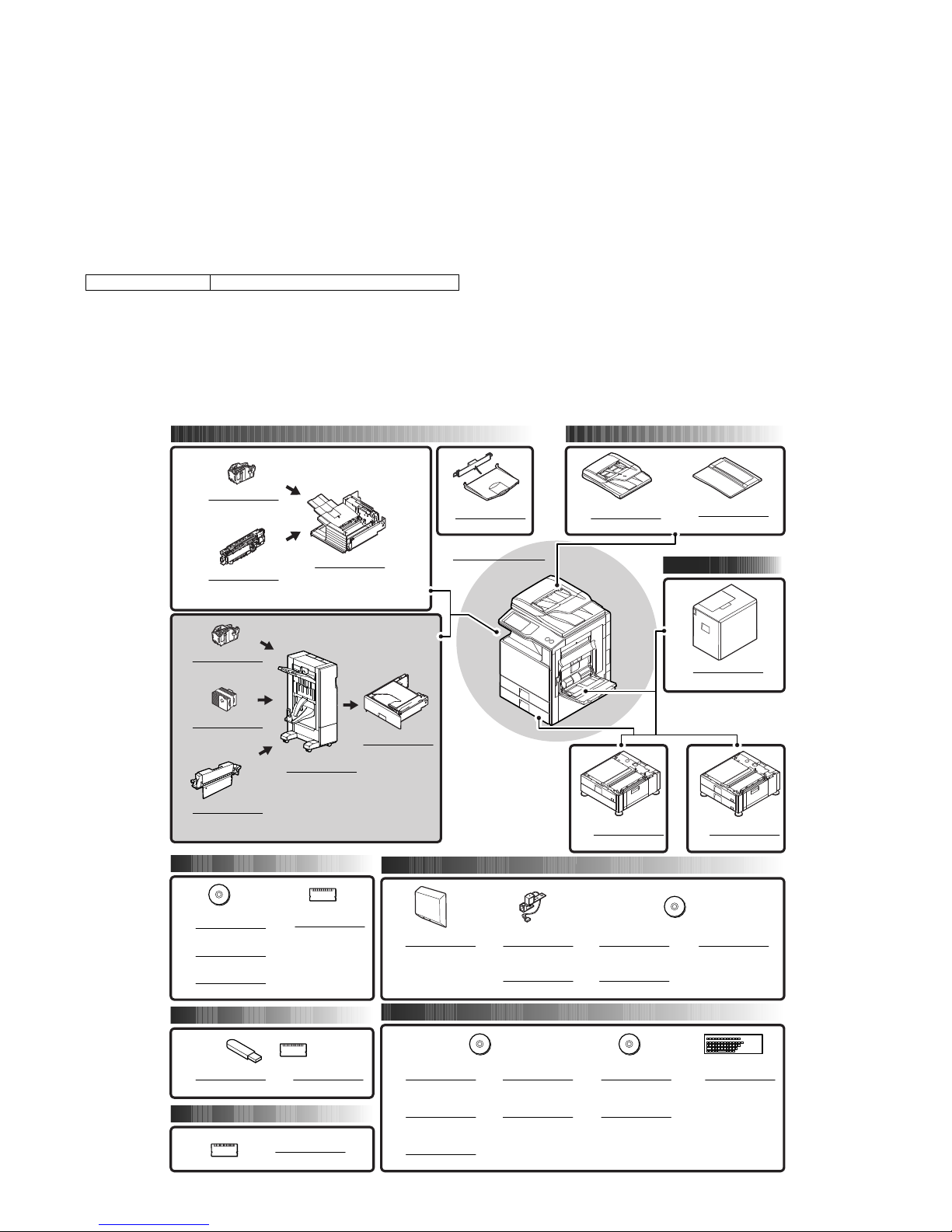
2. Configuration
1) When installing this unit, the paper feed desk (MX-DEX6/DEX7) and the interface unit (MX-RBX3) must be installed together.
2) This unit cannot be installed with the finisher (MX-FNX9) simultaneously.
Applicable models MX-2600N/3100N/2600G/3100G
Paper exit system Document feeder system
Printer expansion
Memory
Authentication/Security
Application/Solution
Image send expansion
Paper feed system
DIGITALFULL COLOR
MULTIFUNCTIONALSYSTEM
MX-2600N/3100N
MX-2600G/3100G
MX-SCX1
FINISHER
MX-FNX9
LARGE CAPACITYTRAY
MX-LCX1
STAND/2x 500 SHEET
PAPERDRAWER
MX-DEX7
PUNCH MODULE
STAPLECARTRIDGE
MX-SCX1
STAPLECARTRIDGE
STAPLECA
(For saddle)
RTRIDGE
MX-PNX1
A/B/C/D
AR-SC3
PUNCH MODULE
MX-PNX5
A/B/C/D
PRINTER
EXPANSIONKIT
MX-PBX3
EXPANSION
MEMORY BOARD
MX-SMX3
PS3 EXPANSION KIT
MX-PKX1
STAMPUNIT
AR-SU1
STAMPCARTRIDGE
AR-SV1
INTERNET FAX
EXPANSIONKIT
MX-FWX1
NETWORK SCANNER
EXPANSIONKIT
MX-NSX1
APPLICATION
INTEGRATIONMODULE
MX-AMX1
XPS EXPANSION KIT
MX-PUX1
BARCODE FONT KIT
AR-PF1
DATA SECURITY KIT
MX-FR10U
DATA SECURITY KIT
MX-FR10
SHARPDESK
5 LICENSE KIT
MX-USX5
KEYBOARD
MX-KBX1
APPLICATION
COMMUNICATIONMODULE
MX-AMX2
EXTERNAL
ACCOUNT MODULE
MX-AMX3
SADDLE STITCH
FINISHER
MX-FN10
PAPERPASS UNIT
MX-RBX3
REVERSING
SINGLE PASS FEEDER
MX-RPX2
DOCUMENT COVER
MX-VRX1
FACSIMILE
EXPANSIONKIT
MX-FXX2
EXIT TRAY UNIT
MX-TRX1
SHARPDESK
1 LICENSE KIT
MX-USX1
SHARPDESK
10 LICENSE KIT
MX-US10
SHARPDESK
50 LICENSE KIT
MX-US50
SHARPDESK
100 LICENSE KIT
MX-USA0
DIGITALFULL COLOR
MULTIFUNCTIONALSYSTEM
MX-2600N/3100N
MX-2600G/3100G
STAND/1x 500 SHEET
PAPERDRAWER
MX-DEX6
Page 4
MX-FN10 SPECIFICATIONS 2 – 1
MX-FN10
Service Manual
[2] SPECIFICATIONS
1. MX-FN10
A. Basic specifications
B. Finishing section
C. Saddle stitch section
D. Consumable parts
Type Console type finisher
Loading method Moving offset tray and saddle stitch exit tray
Transport speed 26/31/35/45/50 ppm
Transport reference Center reference
Mode types Non-staple, staple, saddle stitch/bi-folding
Paper sizes allowed for offset A3, B4, A4, A4R, B5, B5R, 8K, 16K, 16KR, 11" x 17", 8.5" x 14", 8.5" x 13.5", 8.5" x 13.4", 8.5" x 13", 8.5" x 11",
8.5" x 11"R, 7.25" x 10.5"R
Offset quantity 30mm, 1.2 inch
Tray type (Number of trays) Upper tray: Lift-up/down offset tray
Lower tray: Book tray for saddle stitch
Paper exit direction Face down
Paper exit paper size A3W, A3, B4, A4, A4R, B5, B5R, A5R, 8K, 16K, 16KR
12" x 18", 11" x 17", 8.5" x 14", 8.5" x 13.5", 8.5" x 13.4", 8.5" x 13", 8.5" x 11", 8.5" x 11"R, 5.5" x 8.5"R,
7.25" x 10.5"R
Power consumption 70W
Power source Supplied from the host machine power (DC24V/DC5V)
External dimensions (W x D x H) When the paper exit tray is on the storge position: 497 x 631 x 988 (mm), 19-9/16 x 24-53/64 x 38-57/64 (inch)
When the paper exit tray is on the pull-out position: 656 x 631 x 988 (mm), 25-13/16 x 24-53/64 x 38-57/64 (inch)
Occupying dimensions (W x D) When the tray is on pull-out position: 656 x 631 (mm), 25-13/16 x 24-53/64 (inch)
* Distance from the main unit: 300mm, 11 13/16 inch
Weight Approx. 40kg (88 lbs)
Installation/maintenance Installed by service personnel
Optional detection Auto detection supported
Packaged items Parts for mounting, operational sheet, staple directional instruction label, punch directional instrucrtion label,
installation cautionary note
Capacity of paper exit and load Non-staple: 1,000 sheets (Small size) Max. 500 sheets for A5R, 5.5" x 8.5"R (Plain paper 60 to 105g/m2 (16 to
28 lbs) or equivalent)
500 sheets (Large size) (Plain paper 60 to 80g/m
2
(16 to 21 lbs) or equivalent)
Staple sort: 50 sets * (Max. 50 sets for small size, one-position stapling at the rear)
Max: 1,000 sheets (Small size)
500 sheets (Large size)
*: Less than 1,000 sheets and less than 30 sets depending on the use environment and paper curl.
Large size: A3W, A3, B4, 8K, 12" x 18", 11" x 17", 8.5" x 14", 8.5" x 13.5", 8.5" x 13.4", 8.5" x 13"
Small size: A4, A4R, B5, B5R, A5R, 16K, 16KR, 8.5" x 11", 8.5" x 11"R, 5.5" x 8.5"R, 7.25" x 10.5"R
Offset function Provided
Paper size which can be stapled A3, B4, A4, A4R, B5, B5R, 8K, 16K, 16KR, 11" x 17", 8.5" x 14", 8.5" x 13.5", 8.5" x 13.4", 8.5" x 13", 8.5" x 11",
8.5" x 11"R
Ejectable paper size Determinate
size
AB type A3W, A3, B4, A4, A4R, B5, B5R, A5R, 8K, 16K, 16KR
Inch type 12" x 18", 11" x 17", 8.5" x 14", 8.5" x 13.5", 8.5" x 13.4", 8.5" x 13", 8.5" x 11"R,
8.5" x 11", 5.5" x 8.5"R, 7.25" x 10.5"R, 5.5" x 8.5"R
Indeterminate
size
AB type 148 x 100 to 432 x 297
Inch type 5 1/2" x 5 1/2" to 17" x 11 5/8"
Paper weight Thin paper:
Plain paper:
Heavy paper:
55 to 59g/m
2
(15 to 16 lbs)
60 to 105g/m
2
(16 to 28 lbs)
106 to 256g/m
2
(28 to 68 lbs)
Quantity of paper to be stapled (Max.) 50 sheets (Small size, 90g/m
2
(24 lbs))
25 sheets (Large size, 90g/m
2
(24 lbs))
Stapling 3 kinds (One in the front, one at the back, two positions)
Staple supply Staple cartridge replacement
Staple detection Staple empty detection: Provided (Nearly empty: 20 pcs. remained)
Manual stapling No
Stapling type 2-position stapling (center stapling), face down
Folding location Center folding
Paper size A3, B4, A4R, 8K, 16KR, 11" x 17", 8.5" x 14", 8.5" x 11"R
Weight of paper applicable for saddle stitch
60 to 105g/m2 (106 to 209g/m2 (cover 1 sheet)), 16 to 28 lbs (28 to 110 lbs (cover 1 sheet))
Quantity of paper to be stapled 10 sets (11 to 15 sheets), 15 sets (6 to 10 sheets), 20 sets (1 to 5 sheets)
1
Name Content Life Product name
Staple cartridge Staple cartridge x 3 5000 x 3 MX-SCX1
Staple cartridge (for saddle) Staple cartridge x 3 2000 x 3 AR-SC3
: '10/Jun/21
1
Page 5
MX-FN10 SPECIFICATIONS 2 – 2
2. MX-PNX5 A/B/C/D
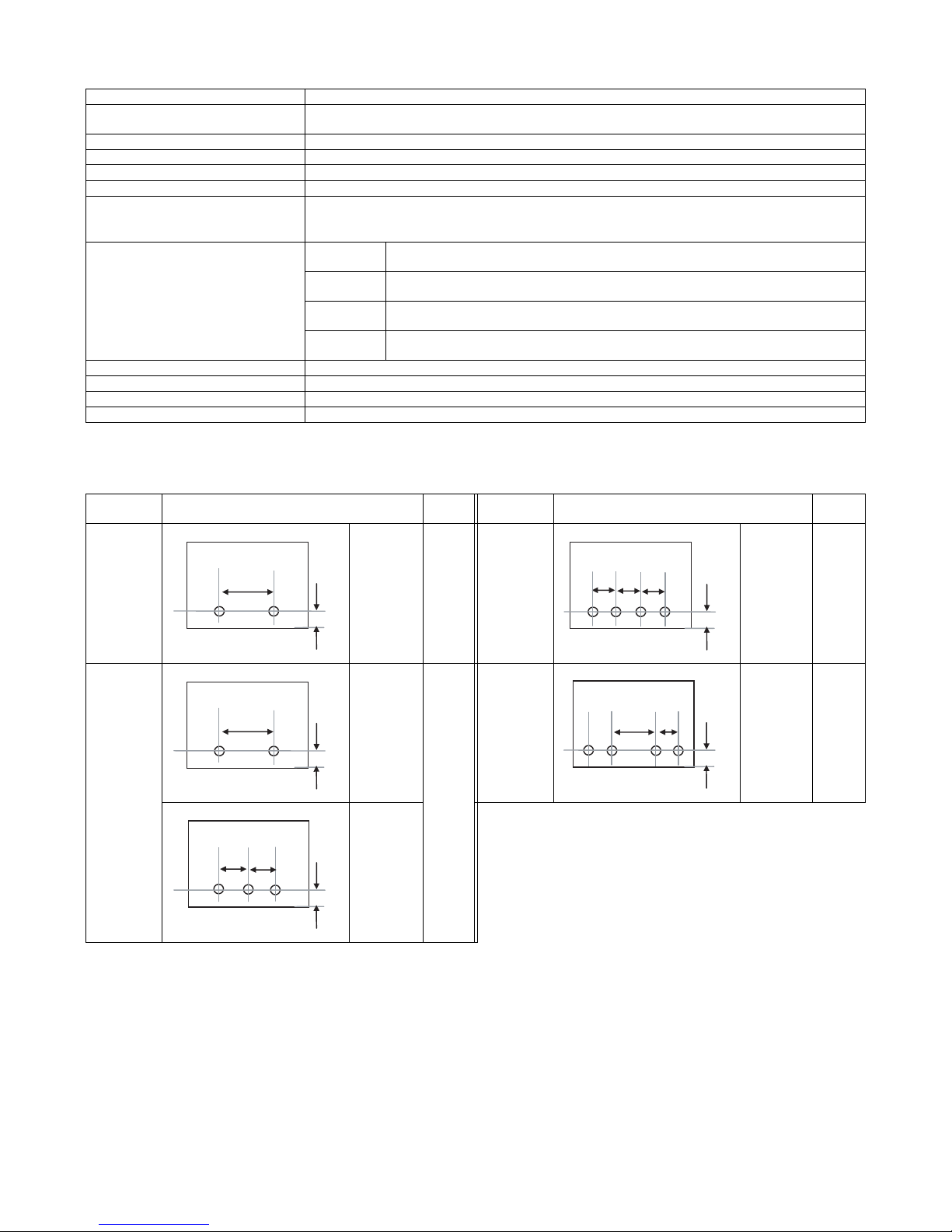
*1: Auto switching: 2 holes/3 holes
Kind of hole punch
Type Punch unit for saddle finisher
Punch type 2 holes / 3 holes / 4 holes / 4 holes (wide)
A punch unit that provides all of these 4 types can be installed.
Transport speed 26, 31, 35, 45, sheets/min.
Transport reference Center reference
Punch dust full detection Provided
Paper exit direction Face down
Paper weight Plain paper: 60 to 105g/m
2
(16 to 28 lbs)
Thin paper: 55 to 59g/m
2
(15 to 16 lbs)
Heavy paper: 106 to 256g/m
2
(28 to 68 lbs)
Puchable paper size 2 holes
(MX-PNX5A)
A3, B4, A4, A4R, B5, B5R, 11" x 17", 8.5" x 14", 8.5" x 13.5", 8.5" x 13.4", 8.5" x 13", 8.5" x 11",
8.5" x 11"R, 8K, 16K, 16KR
3 holes *1
(MX-PNX5B)
3 holes: A3, A4, 11" x 17", 8.5" x 11"
2 holes: 8.5" x 14", 8.5" x 13.5", 8.5" x 13.4", 8.5" x 13", 8.5" x 11"R, 7.25" x 10.5"R
4 holes
(MX-PNX5C)
A3, A4
4 holes (wide)
(MX-PNX5D)
A3, B4, A4, A4R, B5, B5R, 11" x 17", 8.5" x 14", 8.5" x 13.5", 8.5" x 13.4", 8.5" x 13", 8.5" x 11",
8.5" x 11"R
Power source Supplied from the finisher
External dimensions (W x D x H) 120.2 x 600.4 x 244.2 (mm), 4-23/32 x 23-5/8 x 9-39/64 (inch)
Weight Approx. 3.5kg (7.7 lbs)
Packaged items Parts for mounting, instructional label for garbage pickup
Kind Hole position
Hole
size
Kind Hole position
Hole
size
2 holes
(MX-PNX5A)
A: 801mm
B: 123mm
6.5mm 4 holes
(MX-PNX5C)
A: 801mm
B: 123mm
6.5mm
2/3 holes
(MX-PNX5B)
2 holes A: 1081mm
B: 123mm
8.0mm 4 holes
(wide)
(MX-PNX5D)
A: 701mm
B: 123mm
C: 211mm
6.5mm
3 holes A: 701mm
B: 123mm
ABA
B
A
A
ABA
B
C
ABA
Page 6

MX-FN10 SPECIFICATIONS 2 – 3
3. MX-RBX3
Type Paper pass unit
Paper reception reference Center referance
Receiving speed 65 to 450mm/sec (20 to 50cpm)
Receiving and sending speed 20 to 50cpm
Paper weight Thin paper:
Plain paper:
Heavy paper:
55 to 59g/m
2
(15 to 16 lbs)
60 to 105g/m
2
(16 to 28 lbs)
106 to 256g/m
2
(28 to 68 lbs)
Transportable paper sizes A3W, A3, B4, A4, A4R, B5, B5R, A5R, 16K, 16KR
12" x 18", 11" x 17", 8.5" x 14", 8.5" x 13", 8.5" x 11", 8.5" x 11"R, 5.5" x 8.5"R, 7.25" x 10.5"R
External dimensions (W x D x H) 555 x 535 x 165 (mm), 21 27/32 x 21 1/16 x 6 1/2 (inch)
Weight Approx. 7kg (15.4 lbs)
Power source Supplied by saddle finisher
Power consumption Included with saddle finisher power consumption
Interface Mechanical: Fixed to the main unit with screws.
Electrical: Cable connection from the finisher
Control: Controlled by the communication command from the main unit through the finisher.
Installation/maintenance Installed by service personnel
Optional detection Auto detection supported
Packaged items Parts for mounting, installation cautionary note
Page 7
MX-FN10 EXTERNAL VIEWS AND INTERNAL STRUCTURES 4 – 1
MX-FN10
Service Manual
[4] EXTERNAL VIEWS AND INTERNAL STRUCTURES
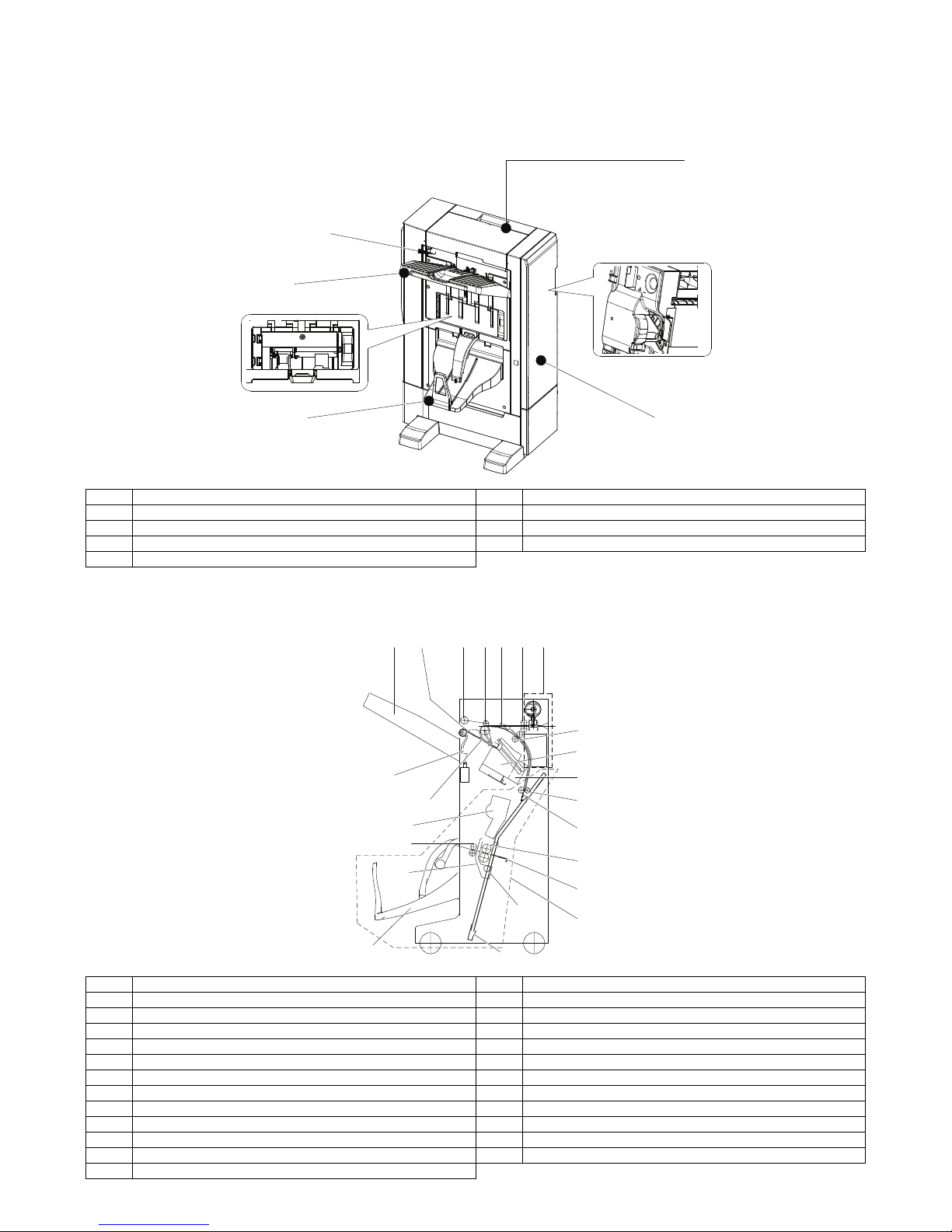
1. Part names and functions
A. External view
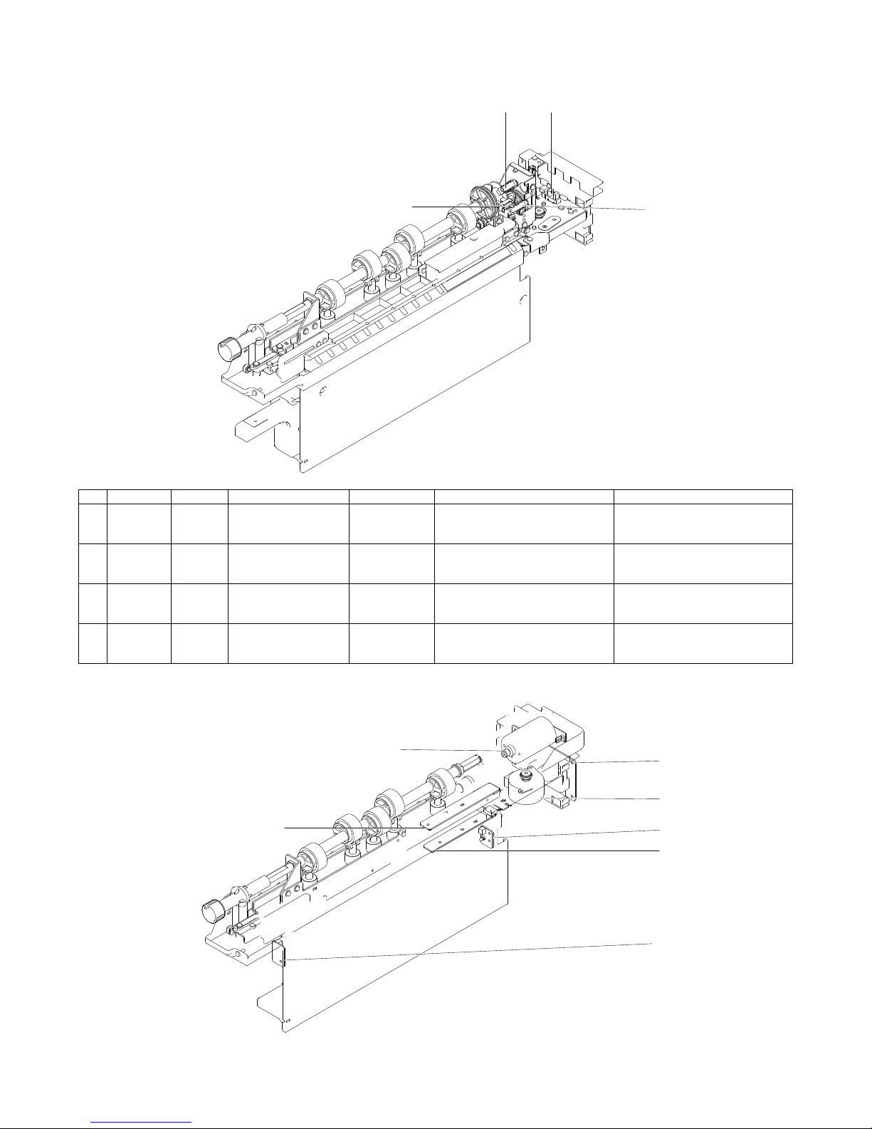
B. Internal structure
(1) Finisher section
No. Name No. Name
1 Staple compiler 5 Offset tray
2 Top cover 6 Saddle stitch tray
3 Edge binding staple section 7 Center binding staple section
4 Front cover
No. Name No. Name
1 Paper exit tray 13 Saddle No. 2 transport roller
2 Alignment plate 14 Paper rear edge holder
3 Paper exit roller 15 Saddle staple unit
4 Process roller 16 Saddle paper exit roller
5 Flapper 17 Folding roller
6 Inlet port transport roller 18 Saddle alignment plate
7 Punch section 19 Saddle No. 3 transport roller
8 Paper holding lever 20 Paper pushing plate
9 Scrabble belt 21 Saddle section
10 Saddle No. 1 transport roller 22 Paper lead edge pushing plate
11 Gripper unit 23 Saddle stitch tray
12 Edge binding staple unit
3
7
1
6
5
4
2
8
9
18
19
15
16
1
23
22
10
11
14
12
17
20
21
13
234567
Page 8
MX-FN10 EXTERNAL VIEWS AND INTERNAL STRUCTURES 4 – 2
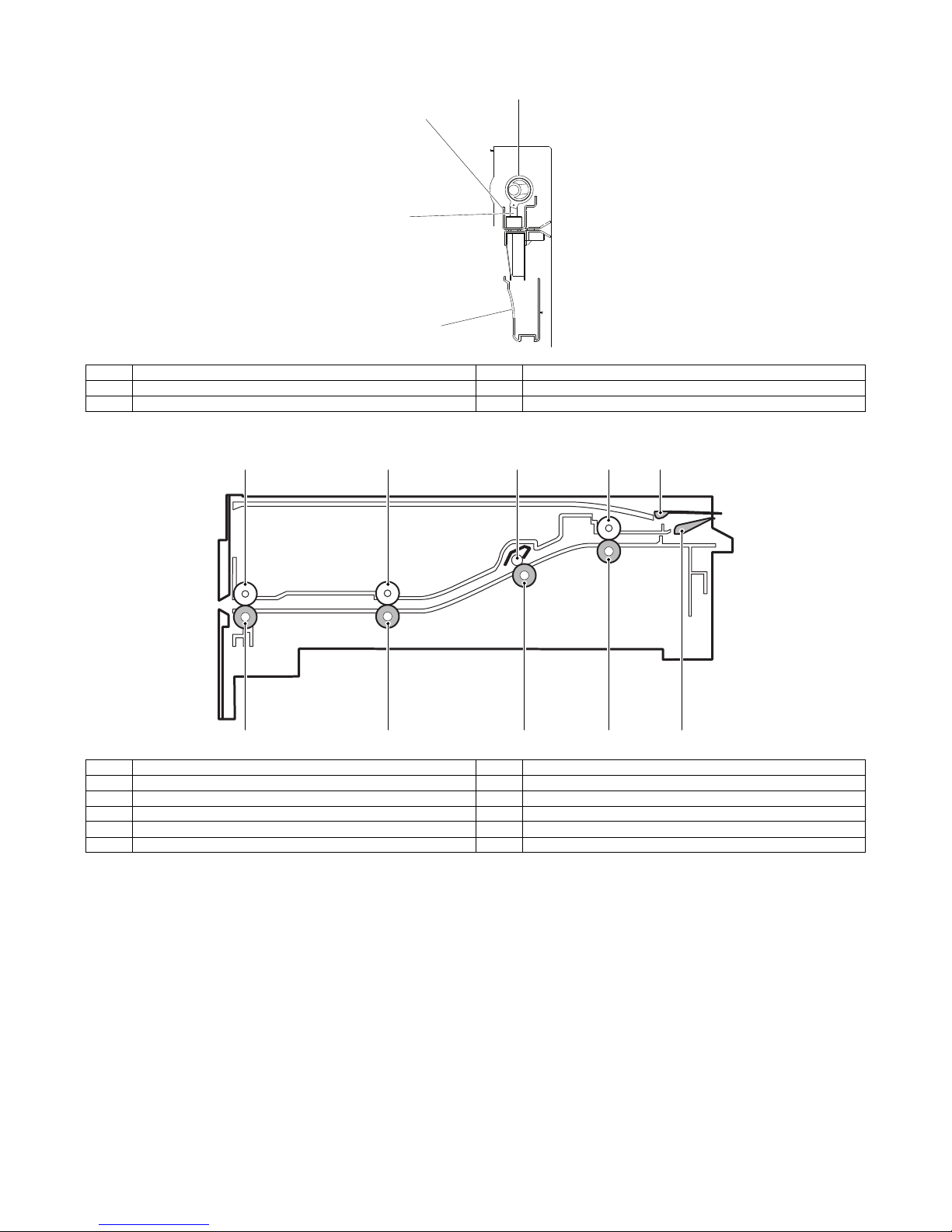
(2) Punch section (Option: MX-PNX5 A/B/C/D)
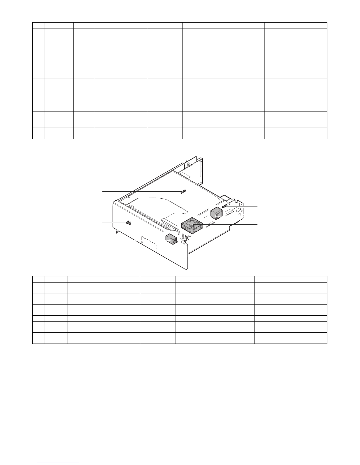
(3) Interface transport section (MX-RBX3)
No. Name No. Name
1 Cam 3 Punch
2 Dice 4 Dust box
No. Name No. Name
1 Paper exit roller 6 Paper exit front roller
2 Paper exit front roller 7 Inlet port rear roller
3 Inlet port rear roller shaft 8 Inlet port roller
4 Inlet port roller 9 Reverse flapper
5 Paper exit roller 10 Upper guide flapper
1
2
3
4
1
5
2
6
4
8
9
10
3
7
Page 9
MX-FN10 EXTERNAL VIEWS AND INTERNAL STRUCTURES 4 – 3
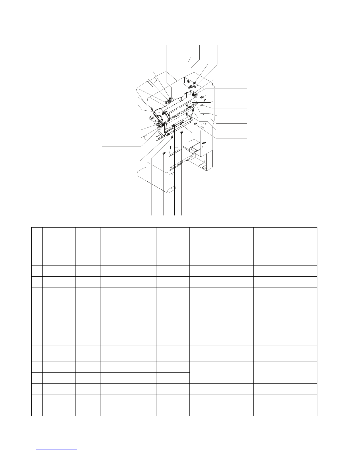
C. Finisher and saddle section
(1) Sensor and switch
No. Code Signal Name Type Function/Operation Output
1 PINS FPPD1 Finisher Paper Pass
Detector 1
Photointerrupter Paper detection at the inlet port of
the finisher
When there is paper, TP1
becomes HI level.
2 EMPS FATPD Finisher Paper Alignment
Tray Paper Detector
Photointerrupter Paper detection on the process
tray
When there is paper, TP26
becomes HI level.
3 SFTEMPS FDTPD Finisher Paper Delivery Tray
Paper Detector
Photointerrupter Paper detection on the load tray When there is paper, TP116
becomes LO level.
4 BDINS FPPD2 Finisher Paper Pass
Detector 2
Photointerrupter Paper detection at the inlet port of
the saddle process section
When there is paper, TP11
becomes HI level.
5 BDOUTS FPPD3 Finisher Paper Pass
Detector 3
Photointerrupter Paper detection at the saddle
paper exit section
When there is paper, TP8
becomes HI level.
6 BDEMPS FSPOD Finisher Saddle Paper
Delivery Tray Paper Detector
Photointerrupter Paper detection on the saddle
load tray
When there is paper, TP4
becomes LO level.
7 BDPASS FSATPD Finisher Saddle Paper
Alignment Tray Paper
Detector
Photointerrupter Paper detection in the saddle
process section
When there is paper, TP4
becomes LO level.
8 RUDS FDRHS Finisher Delivery Roller
Homeposition Sensor
Photointerrupter Detection of the upper standby
position of up/down movement of
the bundle exit roller
When the roller is at the upper
standby position, TP12 becomes
LO level.
9 FJOGHPS FPAPHS_F Finisher Paper Alignment
Plate Homeposition Sensor
(Front)
Photointerrupter Detection of the front side
alignment guide home position
When at home position, TP9
becomes LO level.
10 RJOGHPS FPAPHS_R Finisher Paper Alignment
Plate Homeposition Sensor
(Rear)
Photointerrupter Detection of the rear side
alignment guide home position
When at home position, TP10
becomes LO level.
11 LVLS FPLD Finisher Paper Level
Detector
Photointerrupter Detection of paper surface
position on the load tray by the
combination of both sensor
outputs
* Refer to the separate table
outside the column.
12 LVLHPS FPHHD Finisher Paper Hold
Homeposition Sensor
Photointerrupter
13 GRPHPS FGHPS Finisher Gripper Home
Position Sensor
Photointerrupter Gripper arm HP position
detection
When at home position, TP10
becomes LO level.
14 SLDHPS FSSHPS Finisher Stapler Shift Home
Position Sensor
Photointerrupter Detection of the edge stapler unit
home position in the FR direction
When at home position, TP7
becomes HI level.
15 TOPCOVS FCD2 Finisher Cover Detector 2 Photointerrupter Detection of open/close of the
upper JAM release cover
When the cover is closed, TP15
becomes LO level.
33 - 37
20
23
16
18
4
19
29
1
14
15810311732
27
11
12
9
32
13
30
28
26
62422572125
Page 10

MX-FN10 EXTERNAL VIEWS AND INTERNAL STRUCTURES 4 – 4
Separate table
16 SFTCLKS FTLMRS Finisher Tray Lift Motor
Rotation Sensor
Photointerrupter Detection of abnormality such as
the load tray motor lock.
The output is switched between
HI and LO according to the shift
speed of the load tray lifting and
descending.
17 SFTUPLMT FTULD Finisher Tray Upper Limit
Detector
Photointerrupter Detection of the upper limit
position of up/down shift area of
the paper load tray
When at the upper limit position,
TP1 becomes LO level.
18 SFTDNLMT FTLLD Finisher Tray Lower Limit
Detector
Photointerrupter Detection of the lower limit of up/
down shift area of the paper load
tray
When at the lower limit position,
TP3 becomes LO level.
19 SFTSDNLMT FTPS Finisher Tray Position
Sensor
Photointerrupter Detection of large size paper tray
full
When at the intermediate
position, TP2 becomes LO level.
20 BNDBRDHP FSPHS Finisher Saddle Plate
Homeposition Sensor
Photointerrupter Detection of the saddle pushing
plate home position
When at home position, TP10
becomes LO level.
21 BNDJOGHPS FSAPHS Finisher Saddle Alignment
Plate Homeposition Sensor
Photointerrupter Detection of the saddle alignment
guide home position
When at home position, TP10
becomes LO level.
22 RENDHPS FSPGHS Finisher Saddle Paper Guide
Homeposition Sensor
Photointerrupter Detection of the saddle movable
pushing plate home position
When at home position, TP10
becomes LO level.
23 BNDSLDHPS FSSSHPS Finisher Saddle Stapler Shift
Home Position Sensor
Photointerrupter Detection of the edge stapler unit
home position in FR direction
When at home position, TP7
becomes HI level.
24 BNDR3S FSRHS Finisher Saddle Roller
Homeposition Sensor
Photointerrupter Detection of the saddle process
section transport roller (No. 3
roller) home position
When at home position, TP7
becomes HI level.
25 BNDBRDCLKS FSMRS Finisher Saddle Motor
Rotation Sensor
Photointerrupter Detection of abnormality of the
saddle pushing plate shift speed
control and the motor lock, etc.
The output is switched between
HI and LO according to the speed
of the pushing plate motor.
26 JOGPOSS FSSSW2 Finisher Stapler Safety
Switch 2
Photointerrupter Detection of the edge stapler
clinchable position
When at the clinchable position,
TP7 becomes HI level.
27 GRPOUTS FPDD Finisher Paper Delivery
Detector
Photointerrupter Detection of the gripper arm exit
complete position
When at the gripper exit complete
position, TP7 becomes HI level.
28 FDOORS FCD1 Finisher Cover Detector 1 Photointerrupter Detection of the front door cover
open/close
When the front cover is closed,
TP15 becomes LO level.
29 JOINTS FCD Finisher Connection
Detector
Photointerrupter Detection of connection of the
finisher with the main unit
When connected to the main unit,
TP15 becomes LO level.
30 FDOORSW FSSW1 Finisher Safety Switch 1 Micro switch Detection of open/close of the
jam release cover in the front
section
When the cover is closed, TP15
becomes LO level.
31 STPLSAFESW FSSSW1 Finisher Staple Safty Switch 1Micro switch Assuring the safety against
insertion of a foreign material in
the lift guide section
When the cover is closed, TP15
becomes LO level.
32 BNDSTPRESW FSSCS Finisher Saddle Staple
Cover Sensor
Micro switch Detection of open/close of the
saddle stapler staple replacement
cover
When the cover is closed, TP15
becomes LO level.
33 STPHPS FSSHS Finisher Saddle Staple
Homeposition Sensor
- Detection of the stapling
mechanism home position
(Sensor built in the stapler unit)
When at the home (standby)
position, TP51 becomes HI level.
34 STPEMPS FSSES Finisher Saddle Staple
Empty Sensor
- Detection of staple empty (sensor
built in the stapler unit)
When staple empty, TP53
becomes LO level.
35 STPSLFPS FSLS Finisher Staple Lead Sensor - Detection of stapling enable state
after completion of staple feed
(sensor built in the stapler unit)
When in the READY state, TP52
becomes HI level.
36 BNDSTPHP FSHS Finisher Staple
Homeposition Sensor
- Dete ction the stapling mechanism
home position (sensor built in the
stapler unit)
When at the home (standby)
position, TP51 becomes HI level.
37 BNDSTPEMP FSED Finisher Staple Empty
Detector
- Detection of staple empty (sensor
built in the stapler unit)
When staple empty, TP53
becomes LO level.
LVL S LV LH PS
Status
TP71 TP13
LO LO Detection of a low position of the paper surface on the load tray.
LO HI Detection of retraction of the paper surface lever.
HI LO Detection of the paper surface position on the load tray.
HI HI Detection of a high position of the paper surface on the load tray.
No. Code Signal Name Type Function/Operation Output
Page 11
MX-FN10 EXTERNAL VIEWS AND INTERNAL STRUCTURES 4 – 5
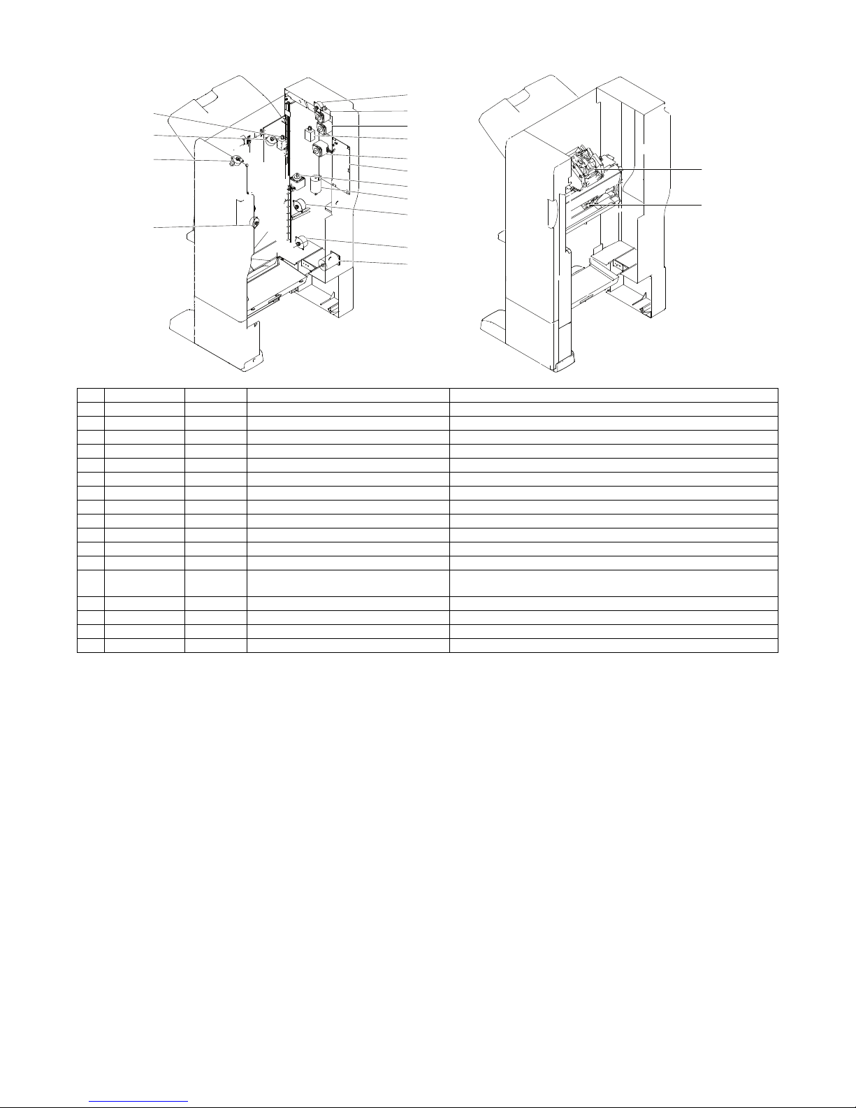
(2) Motor and PWB
No. Code Signal Name Function
1 FEEDMOT1 FPTM1 Finisher Paper Transport Motor 1 Drives the inlet port roller and the feed roller.
2 FEEDMOT2 FPTM2 Finisher Paper Transport Motor 2 Drives the feed roller and the scrabbling belt.
3 GRPMOT FGM Finisher Gripper Motor Shifts the gripper arm in the exit/save direction.
4 ROMOT FDRLM Finisher Delivery Roller Lift Motor Drives the bundle exit roller up and down.
5 SIFTMOT FTLM Finisher Tray Lift Motor Drives the paper load tray up and down.
6 FJOGMOT FPAM-F Finisher Paper Alignment Motor F Drives the alignment guide on the front side.
7 RJOGMOT FPAM-R Finisher Paper Alignment Motor R Drives the alignment guide on the rear side.
8 BNDJOGMOT FSPAM Finisher Saddle Paper Alignment Motor Drives the saddle alignment guide.
9 RENDMOT FSPM Finisher Saddle Positioning Motor Drives the saddle folding position guide.
10 BNDR3MOT FSPTM Finisher Saddle Paper Transport Motor Drives No. 3 paper transport roller.
11 SLDMOT FSSM Finisher Stapler Shift Motor Shifts the stapler unit in the FR direction.
12 BNDBRDMOT FSDM Finisher Saddle Motor Drives the saddle folding plate.
13 LVLSOL FPHS1 Finisher Paper Holding Solenoid 1 Drives the lever for paper holding and detection of the paper surface in
the load tray.
14 PPRSSOL FPHS2 Finisher Paper Holding Solenoid 2 Holds paper in the process section.
15 Finisher Control PWB Controls the finisher.
16 BNDSTPLMOT FSM Finisher Staple Motor Drives the stapling mechanism. (Stapler unit built-in motor)
17 STPLMOT FSDSM Finisher Saddle Staple Motor Drives the stapling mechanism. (Stapler unit built-in motor)
13
7
6
8
4
1
2
14
3
15
11
16
17
5
10
9
12
Page 12
MX-FN10 EXTERNAL VIEWS AND INTERNAL STRUCTURES 4 – 6
D. Punch section (Option: MX-PNX5 A/B/C/D)
(1) Sensor
(2) Motor and PWB
No. Code Signal Name Type Function/Operation Output
1 PNCHPOS FPPS Finisher Punch Paper
Position Sensor
Photointerrupter Detects the punch rotating position. When at home position, TP47 on the
control PWB of the finisher becomes
HI level.
2 PNCHHP FPCHPS Finisher Puncher Cam
Home Position Sensor
Photointerrupter Detects the lower limit position on the
3-hole side in the 2/3-hole punch.
When at the lower limit position, TP48
on the control PWB of the finisher
becomes HI level.
3 PNCHCLK FPMRS Finisher Punch Motor
Rotation Sensor
Photointerrupter Controls the punch position and
detects the motor lock.
When at home position, TP49 on the
control PWB of the finisher becomes
HI level.
4 SLDHP FPHPS Finisher Puncher Home
Position Sensor
Photointerrupter Detects the home position of the
punch position horizontal resist
correction mechanism.
When at home position, TP49 on the
control PWB of the finisher becomes
HI level.
2
14
3
1
3
2
6
5
7
4
Page 13
MX-FN10 EXTERNAL VIEWS AND INTERNAL STRUCTURES 4 – 7
E. Interface transport section (MX-RBX3)
No. Code Signal Name Type Function/Operation Output
1 PNCH_MOT FPM Finisher Punch Motor Drives the punch unit up and down.
2 SLDMOT FPSM Finisher Punch Shift Motor Shifts the punch unit to the center of paper.
3 Punch Control PWB Controls the punch.
4, 5 REGTIMS FPTS Finisher Punch Timing
Sensor
Transmission
type photo
sensor
Detects the lead edge and the rear edge of
paper to be punched.
When there is paper, TP54 on
the control PWB of the finisher
becomes LOW level.
4, 5 SIZE_B5R FPES1 Finisher Punch Paper
Edge Sensor 1
Transmission
type photo
sensor
Detects the paper edge on the rear of the
machine in the width direction of E5R and
EXE-R size.
When there is paper, TP55 on
the control PWB of the finisher
becomes LOW level.
4, 5 SIZE_A4R FPES2 Finisher Punch Paper
Edge Sensor 2
Transmission
type photo
sensor
Detects the paper edge on the rear side of
the machine in the width direction of LGL,
LTR-R, FS, and A4R size.
When there is paper, TP55 on
the control PWB of the finisher
becomes LOW level.
4, 5 SIZE_B4R FPES3 Finisher Punch Paper
Edge Sensor 3
Transmission
type photo
sensor
Detects the paper edge on the rear side of
the machine in the width direction of EXE,
B4, and B5 size.
When there is paper, TP55 on
the control PWB of the finisher
becomes LOW level.
4, 5 SIZE_A3 FPES4 Finisher Punch Paper
Edge Sensor 4
Transmission
type photo
sensor
Detects the paper edge on the rear side of
the machine in the width direction of A3,
A3 wide, and A4 size.
When there is paper, TP55 on
the control PWB of the finisher
becomes LOW level.
6, 7 DUST FPDFS Finisher Punch Dust Full
Sensor
Photointerrupter Detects full of the punch dust box. When full, TP2 on the punch
PWB remains HI level.
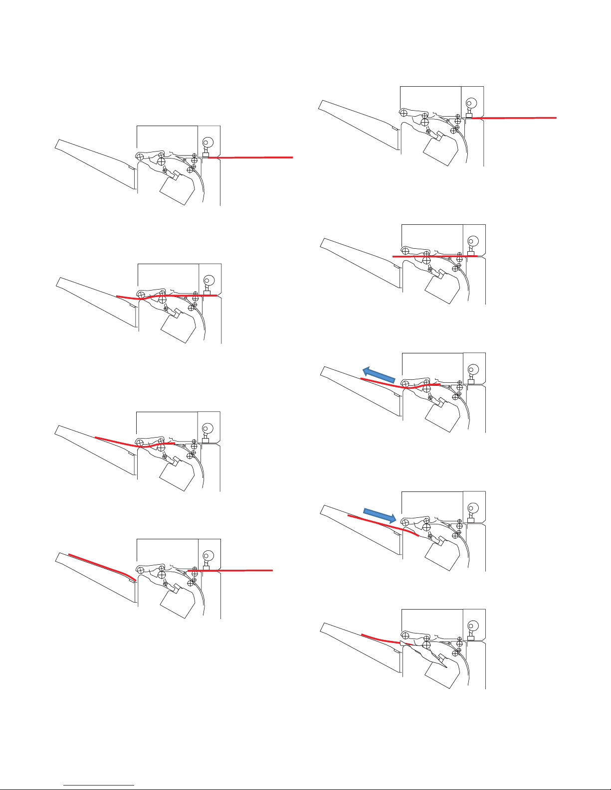
No. Signal Name Type Function/Operation Output
1 PDPPD1 Interface transport unit inlet port
sensor
Photointerrupter Interface inlet port paper detection LO light is interrupted when paper is
provided.
2 PDPPD2 Interface transport unit outlet port
sensor
Photointerrupter Interface outlet port paper detection LO light is interrupted when paper is
provided.
3 PDCS Interface transport unit cover sensor Photointerrupter Interface cover open detection Light is interrupted when the cover is
open.
4 PDPTM Interface transport motor Paper transport roller drive
5 PDPGS Interface reverse path solenoid Drive of the flapper which selects the
path in the finisher and the reverse path
6 PDCF Interface fan Temperature rise protection fan in the
finisher inlet port section
2
3
5
6
4
1
Page 14
MX-FN10 OPERATIONAL DESCRIPTION 5 – 1
MX-FN10
Service Manual
[5] OPERATIONAL DESCRIPTION
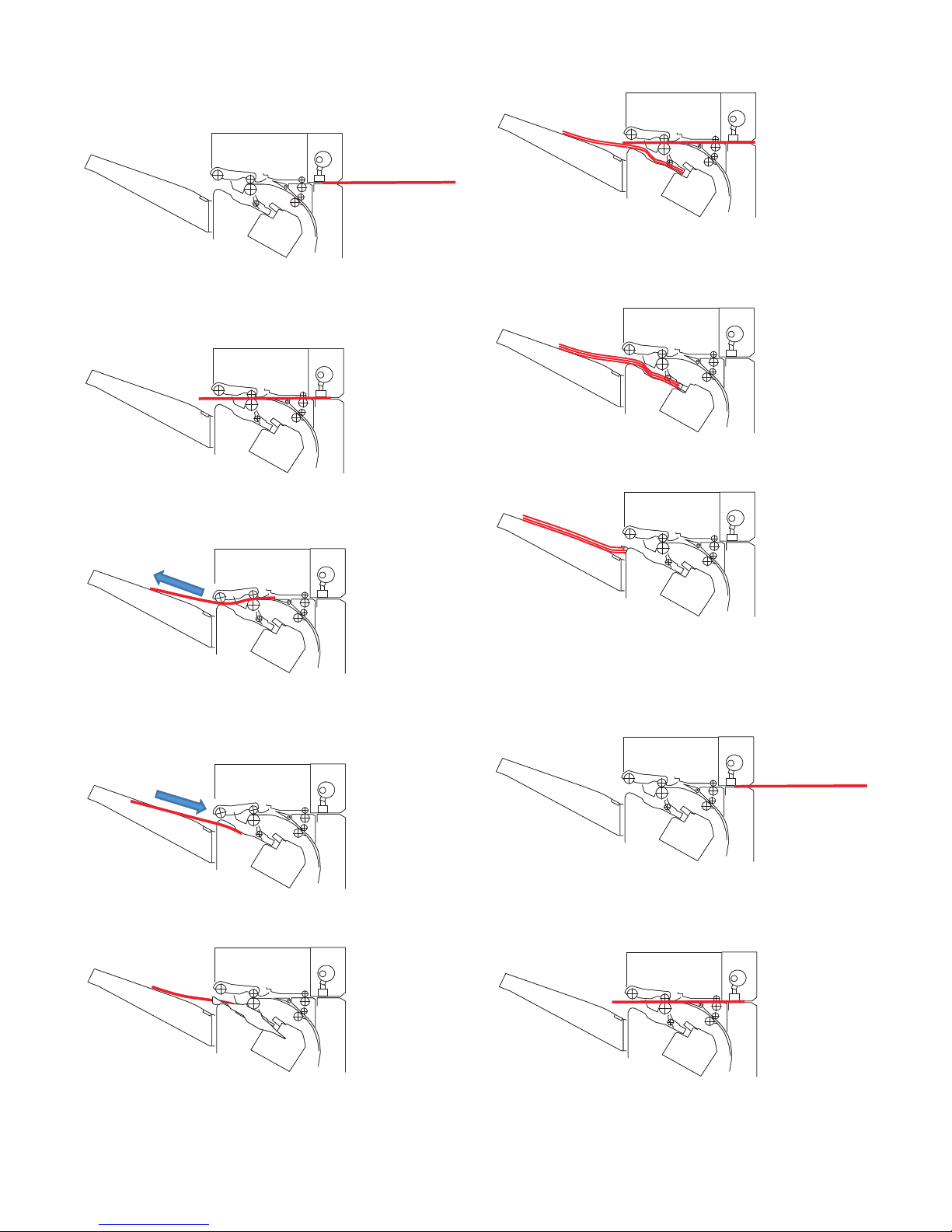
1. Straight paper exit mode
1) The transport motor and the transport motor 2 are driven at the
paper exit speed of the main unit, and paper is discharged
from the main unit.
At that time, the paper exit roller goes into the nip state.
2) The inlet port sensor turns on, and the paper rear edge
reaches the specified position. Then the speed of the transport
motor and the transport motor 2 is changed to the inside-themain unit speed.
3) The inlet port sensor turns OFF and the paper rear edge
reaches the specified position. Then the speed of the transport
motor is changed to the paper exit speed of the main unit, and
the speed of the transport motor 2 is changed to the stack tray
paper exit speed.
4) When the paper rear edge goes out of the paper exit roller, the
speed of the transport motor 2 is changed to the paper exit
speed of the main unit.
2. Non staple mode
1) The transport motor and the transport motor 2 are driven at the
paper exit speed of the main unit, and paper is discharged
from the main unit.
2) The inlet port sensor turns on, and the paper rear edge
reaches the specified position. Then the speed of the transport
motor and the transport motor 2 is changed to the inside-themain unit speed.
3) The inlet port sensor turns OFF and the paper rear edge
reaches the specified position. Then the speed of the transport
motor is changed to the paper exit speed of the main unit.
4) When the paper rear edge reaches the reverse position for
storing to the process tray, the transport motor 2 is temporarily
stopped. Then the transport motor 2 reverses to store paper in
the process tray.
5) When paper is stored in the process tray, the alignment plate
reciprocates to align paper.
Page 15
MX-FN10 OPERATIONAL DESCRIPTION 5 – 2
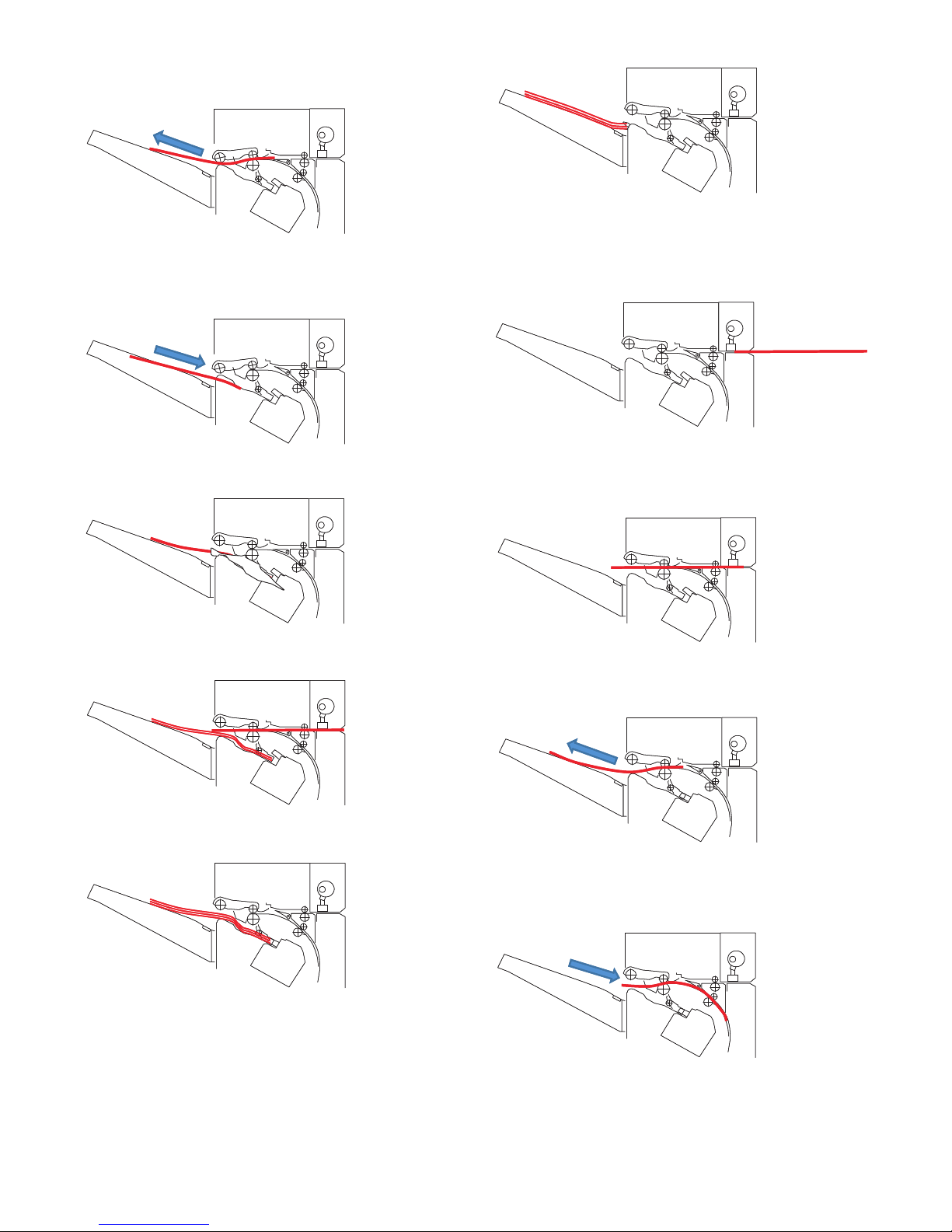
6) Reception of paper in the process tray is repeated until the
specified number of sheet for a bundle is stacked. (1 - 5)
7) When all the sheets of paper in a bundle are discharged to the
process tray, the paper bundle is discharged to the stack tray
by the gripper.
3. Rear on position staple mode
1) The transport motor and the transport motor 2 are driven at the
paper exit speed of the main unit, and paper is discharged
from the main unit.
2) The inlet port sensor turns on, and the paper reaches the
specified position. Then the speed of the transport motor and
the transport motor 2 is changed to the inside-the-main unit
speed.
3) The inlet port sensor turns OFF and the paper rear edge
reaches the specified position. Then the speed of the transport
motor is changed to the paper exit speed of the main unit.
4) When the paper rear edge reaches the reverse position for
storing to the process tray, the transport motor 2 is temporarily
stopped. Then the transport motor 2 reverses to store paper in
the process tray.
5) When paper is stored in the process tray, the alignment plate
reciprocates to align paper.
6) Reception of paper in the process tray is repeated until the
specified number of sheet for a bundle is stacked. (1 - 5)
7) When all the sheets of a bundle are discharged to the process
tray, stapling is performed.
8) After stapling, the paper bundle is discharged to the stack tray
by the gripper.
Page 16
MX-FN10 OPERATIONAL DESCRIPTION 5 – 3
4. 2-position staple mode
1) The transport motor and the transport motor 2 are driven at the
paper exit speed of the main unit, and paper is discharged
from the main unit.
2) The inlet port sensor turns on, and the paper reaches the
specified position. Then the speed of the transport motor and
the transport motor 2 is changed to the inside-the-main unit
speed.
3) The inlet port sensor turns OFF and the paper rear edge
reaches the specified position. Then the speed of the transport
motor is changed to the paper exit speed of the main unit.
4) When the paper rear edge reaches the reverse position for
storing to the process tray, the transport motor 2 is temporarily
stopped. Then the transport motor 2 reverses to store paper in
the process tray.
5) When paper is stored in the process tray, the alignment plate
reciprocates to align paper.
6) Reception of paper in the process tray is repeated until the
specified number of sheet for a bundle is stacked. (1 - 5)
7) When all the sheets of a bundle are discharged to the process
tray, stapling at the first position is performed. After completion
of the first stapling, the staple unti is shfited to the second staplingposition and the second stapling is performed.
8) After completion of the second stapling, the paper bundle is
discharged to the stack tray by the gripper.
5. Front one position staple mode
1) The transport motor and the transport motor 2 are driven at the
paper exit speed of the main unit, and paper is discharged
from the main unit.
2) The inlet port sensor turns on, and the paper reaches the
specified position. Then the speed of the transport motor and
the transport motor 2 is changed to the inside-the-main unit
speed.
Page 17
MX-FN10 OPERATIONAL DESCRIPTION 5 – 4
3) The inlet port sensor turns OFF and the paper rear edge
reaches the specified position. Then the speed of the transport
motor is changed to the paper exit speed of the main unit.
4) When the paper rear edge reaches the reverse position for
storing to the process tray, the transport motor 2 is temporarily
stopped. Then the transport motor 2 reverses to store paper in
the process tray.
5) When paper is stored in the process tray, the alignment plate
reciprocates to align paper.
6) Reception of paper in the process tray is repeated until the
specified number of sheet for a bundle is stacked. (1 - 5)
7) When all the sheets of a bundle are discharged to the process
tray, stapling is performed.
8) After stapling, the paper bundle is discharged to the stack tray
by the gripper.
6. Saddle motor
1) The transport motor and the transport motor 2 are driven at the
paper exit speed of the main unit, and paper is discharged
from the main unit.
2) The inlet port sensor turns on, and the paper reaches the
specified position. Then the speed of the transport motor and
the transport motor 2 is changed to the inside-the-main unit
speed.
3) The inlet port sensor turns OFF and the paper rear edge
reaches the specified position. Then the speed of the transport
motor is changed to the paper exit speed of the main unit.
4) When the paper rear edge reaches the reverse position for
storing to the saddle process tray, the transport motor 2 is temporarily stopped. Then the transport motor 2 reverses to store
paper in the saddle process tray.
Page 18

MX-FN10 OPERATIONAL DESCRIPTION 5 – 5
5) When paper is stored in the saddle process tray, the alignment
plate reciprocates to align paper.
6) Reception of paper in the saddle process tray is repeated until
the specified number of sheet for a bundle is stacked. (1 - 5)
7) When all the sheets of a bundle are discharged to the saddle
process tray, stapling is performed.
8) After completion of stapling, the paper stopper is lowered to
shift the paper bundle to the paper folding position.
Page 19

MX-FN10 OPERATIONAL DESCRIPTION 5 – 6
9) Start the pushing plate motor to fold the paper bundle and discharge it.
10) The paper bundle is discharged to the saddle stack tray by the
saddle exit motor.
7. Punch process
1) When the paper lead edge passes the paper rear edge detection sensor, the punch horizontal registration motor is booted
to start the horizontal registration.
2) After starting horizontal registration, when the horizontal registration sensor detects the side edge, it is shifted by the specified distance to stop the punch horizontal registration motor.
3) When the paper rear edge passes the paper rear edge detection sensor, the transport motor and the transport motor 2 are
stopped to stop paper.
4) When paper is stopped, the punch motor is booted to punch at
the paper rear edge.
5) After completion of punching, the transport motor and the
transport motor 2 are booted to start paper transport, executing the specified after-process.
Page 20

MX-FN10 DISASSEMBLY AND ASSEMBLY 6 – 1
MX-FN10
Service Manual
[6] DISASSEMBLY AND
ASSEMBLY
1) Turn off the main power, and disconnect the connector of the
saddle finisher.
2) Open the front door, and release the lock.
Remove the saddle finisher from the main unit.
1. Saddle finisher
A. External outfit control items
(1) Load tray
1) Remove the load tray.
(2) Saddle paper holding lever
1) Remove the movable lever.
2) Remove the fixing lever.
(3) Saddle tray
1) Remove the saddle tray.
Page 21

MX-FN10 DISASSEMBLY AND ASSEMBLY 6 – 2
(4) Front cabinet
1) Remove the front lower cover.
2) Open the front door, and remove the front cabinet.
(5) Rear cabinet upper
1) Remove the rear cabinet upper.
(6) Rear cabinet lower
1) Remove the front lower cover. (See (4).)
2) Remove the rear cabinet upper. (See (5).)
3) Remove the foot cover.
4) Remove the rear cabinet lower.
(7) Upper door
1) Remove the front cabinet. (See (4).)
2) Remove the rear cabinet upper. (See (5).)
3) Remove the upper door.
(8) Right cabinet
1) Remove the front cabinet. (See (4).)
2) Remove the rear cabinet. (See (5).)
3) Remove the right cabinet.
Page 22

MX-FN10 DISASSEMBLY AND ASSEMBLY 6 – 3
(9) Right lower cover
1) Loosen the screw [1].
2) Remove the right lower cover.
(10) Side guide upper
1) Remove the load tray. (See (1).)
2) Remove the saddle paper holding lever. (See (2).)
3) Remove the saddle tray. (See (3).)
4) Remove the front cabinet. (See (4).)
5) Remove the rear cabinet upper. (See (5).)
6) Put the load tray supporting plate (front) [1] and the load tray
supporting plate (rear) [2] outside of the rail groove.
Note: When the load tray is on the top position, lower the load
tray by manually turning the load tray lift motor rotation
shaft (counterclockwise) so that the sensor flag attached
to the supporting plate (rear) does not make contact with
the load tray upper limit sensor.
7) Open the center binding staple replacement door, and release
the center binding staple lock.
8) Disconnect two connectors on the left side of the side guide
upper.
9) Remove the side guide upper.
(11) Side guide lower
1) Remove the side guide upper. (See (10).)
2) Remove the side guide lower.
NOTE: When assembling, place the polyester film (2 positions) on
each side of the side guide lower and attach.
[1]
[1]
[2]
Page 23

MX-FN10 DISASSEMBLY AND ASSEMBLY 6 – 4
B. Transport section
(1) Center binding stapler unit removal
1) Remove the harness duct and the center binding staple
replacement door switch.
2) Remove the center binding harness guide and the upper and
lower stapler connection parts.
3) Remove the center binding stapler earth wire fixing screw.
4) Remove the center binding stapler unit fixing screw. (5 positions)
5) Pull out the center binding stapler unit.
(2) Center binding stapler removal
1) Remove the unit frame.
2) Slide the stapler to the front, and remove the connector and
the earth wire fixing screw.
Page 24

MX-FN10 DISASSEMBLY AND ASSEMBLY 6 – 5
3) Remove the stapler fixing screws (3 positions).
4) Remove the stapler.
(3) Edge binding stapler removal
1) Slide the stapler to the front.
2) Remove the latch for connection of the main unit.
3) Remove two stapler fixing screws from the hole in circle in the
figure below.
At that time, shift the stapler and fit the screw with the hole
position.
4) Remove the stapler.
(4) Saddle pushing plate motor gear box removal
1) Remove the grip, the E-ring, and the bearing which are fixing
each gear shaft.
Page 25

MX-FN10 DISASSEMBLY AND ASSEMBLY 6 – 6
2) Remove the interface cable facing part.
Remove the gear box fixing screw.
3) Remove the gear box.
(5) Transport motor assembly
1) Remove the rear cabinet upper. (See A-(5).)
2) Remove the screw, and remove the transport motor assembly.
(6) Load tray lift motor gear box
1) Remove the rear cabinet upper. (See A-(5).)
2) Remove the saddle finisher control PWB fixing part. (See C(2).)
3) Remove the gear box.
C. PWB section
(1) Saddle finisher control PWB
1) Remove the rear cabinet upper. (See A-(5).)
2) Remove the PWB fixing screw, and disconnect each connector, release the PWB holding pawl, and remove the PWB.
Page 26

MX-FN10 DISASSEMBLY AND ASSEMBLY 6 – 7
(2) Saddle finisher control PWB fixing parts
1) Remove the control PWB. (See (1).)
2) Remove the screw, and remove the PWB fixing part.
2. Paper Transport Section (MX-RBX3)
A. Paper Pass Unit
1) Pull out the paper pass unit, and remove the screw.
2) Free the lock, to remove the paper pass unit.
(1) Paper transport unit entry sensor
1) Remove the paper pass unit.
2) Remove the paper transport unit entry sensor.
(2) Paper transport unit exit sensor
1) Remove the paper pass unit.
2) Remove the bracket, and remove the paper transport unit exit
sensor.
(3) Upper Guide Flapper
1) Remove the paper pass unit.
2) Open the upper transport unit, remove each parts, and remove
the reverse gate.
1
2
3
Page 27

MX-FN10 DISASSEMBLY AND ASSEMBLY 6 – 8
(4) Interface Fan
1) Remove the paper pass unit.
2) Remove the bottom cover.
3) Remove the clamps, and disconnect the connector then
remove the interface fan.
* Install the interface fan so as the side with the label (A)
comes to the direction illustrated.
(5) Interface Transport Motor
1) Remove the paper pass unit.
2) Remove the bottom cover. (See (4).)
3) Disconnect the connector, then remove the interface transport
motor.
(6) Entry Reverse Pass Solenoid.
1) Remove the paper pass unit.
2) Remove the bottom cover. (See (4).)
3) Remove the front cover.
4) Remove the solenoid unit.
5) Remove each parts, then remove the entry reverse pass solenoid.
* Adjust so that the distance between the lower guide and the
upper guide flapper is 22mm with the solenoid plunger
pushed in. Install the entry reverse pass solenoid.
1
2
2
3
A
1
2
3
1
2
22mm
Page 28

MX-FN10 DISASSEMBLY AND ASSEMBLY 6 – 9
(7) Entry Roller
1) Remove the paper pass unit.
2) Remove the bottom cover. (See (4).)
3) Remove the interface transport motor. (See (5).)
4) Remove the front cover. (See (6).)
5) Remove the stopper band, and the bracket, then remove the
upper guide unit.
* When installing, adjust so that the solenoid is fit with the
bracket adjustment reference. If the upper guide unit magnet lifts up, adjust the bracket for the magnet not to lift up.
6) Remove each parts, then remove the entry roller.
(8) Post Entry Roller
1) Remove the paper pass unit.
2) Remove the bottom cover. (See (4).)
3) Remove the front cover. (See (6).)
4) Remove the upper guide unit. (See (7).)
5) Remove the bracket, and remove the post entry roller unit.
6) Remove each parts, and remove the post entry roller.
(9) Pre Entry Roller
1) Remove the paper pass unit.
2) Remove the bottom cover. (See (4).)
3) Remove the front cover. (See (6).)
4) Remove the upper guide unit. (See (7).)
5) Remove each parts, and remove the pre entry roller.
2
2
3
1
Adjustment
reference
± 0.5
Page 29

MX-FN10 DISASSEMBLY AND ASSEMBLY 6 – 10
(10) Exit Roller
1) Remove the paper pass unit.
2) Remove the bottom cover. (See (4).)
3) Remove the front cover (See (6).)
4) Remove the upper guide unit. (See (7).)
5) Remove the drawer bracket.
Remove each parts and remove the exit roller.
B. Reverse Tray Unit
(1) Reverse Flapper
1) Remove the paper pass unit.
2) Remove the reverse tray.
3) Remove each parts, and remove the reverse flapper.
C. Left Cabinet Unit
(1) Interface Transport Unit Cover Detection Sensor
1) Remove the paper pass unit.
2) Remove the reverse tray. (See B-(1).)
3) Free the lock, then remove the saddle stitch finisher.
4) Remove the left cover.
5) Disconnect the connector, and the sensor bracket. Remove
the interface transport unit cover detection sensor.
(2) Paper Pass PWB
1) Remove the paper pass unit.
2) Remove the reverse tray. (See B-(1))
3) Remove the left cover. (See C-(1).)
4) Remove allen screw, remove the interface PWB, then remove
the connector.
1
2
3
4
Page 30

MX-FN10 DISASSEMBLY AND ASSEMBLY 6 – 11
3. Punch section
A. Punch drive section
(1) Punch motor removal
1) Remove the upper cover. (Remove two screws.)
2) Remove the rear blinding cover. (Remove two screws.)
3) Remove the jam process knob, the screw, and the sensor
holding part.
4) Remove the shaft reception part (front), the bearing, and the
screw, and remove the screw of the shaft reception part (rear).
5) Remove the shift.
6) Remove the screw and the motor.
a
a
Page 31

MX-FN10 DISASSEMBLY AND ASSEMBLY 6 – 12
B. PWB section
(1) Punch control PWB
1) Turn the screw and remove the control PWB in the arrow
direction.
(2) Light receiving dust sensor 2
1) Pull out the punch dust box in the arrow direction.
2) Remove the screw which is fixing the sensor cover.
3) Pull out in the arrow direction [1], and remove in the arrow
direction [2].
4) Remove the screw which is fixing the dust sensor, and turn the
dust sensor in the arrow direction.
5) Remove the screw which is fixing the sensor cover.
6) Pull out the sensor cover <1> in the arrow direction.
7) Pull out in the arrow direction <1>, and remove the arrow
direction <2>.
8) Remove the screw which is fixing the dust sensor.
9) Remove the dust sensor in the arrow direction.
[2]
[1]
[2]
[1]
Page 32

MX-FN10 DISASSEMBLY AND ASSEMBLY 6 – 13
(3) Light receiving side registration sensor removal
1) Remove the screw which is fixing the registration sensor.
2) Remove the registration sensor cover in the arrow direction.
3) Remove the registration sensor in the same direction as the
cover.
(4) Light emitting registration sensor removal
1) Pull out the jam process knob in the arrow direction, and
remove the screw.
2) Remove two screws.
3) Remove the spring in the arrow direction.
4) Remove the harness duct in the arrow direction.
5) Separate the upper and the lower sections. (Pull up in the
arrow direction.)
6) Remove the screw, and remove the sensor cover in the arrow
direction.
7) Remove the registration sensor in the same direction as the
cover.
Page 33

MX-FN10 MAINTENANCE 7 – 1
MX-FN10
Service Manual
[7] MAINTENANCE
1. Maintenance System Table
: Check (Clean, replace, or adjust as necessary.) : Clean : Replace : Adjust ✩: Lubricate : Move position
No. Part name
When
calling
100K200K300K400K500K600K700K800K900K1000K110 0
K
Remark
1 Transport rollers
2 Transport paper guides
3Gears When checking, apply to the necessary
positions. (Specified positions)
4Belts
5 Knurled belt Replacement reference: Replace at
every 1000K of the finisher paper exit
count value.
6Sensors
7 Discharge brush
8 Stapler unit Replacement reference: Replace the unit at every 200K staple.
9 Stapler unit for saddle Replacement reference: Replace the unit at every 100K staple.
10 Punch unit Replacement reference: Replace the unit at every 1000K.
11 Staple cartridge User replacement for every 5000pcs.
12 Staple cartridge for saddle User replacement for every 2000pcs.
6
6
6
6
66 6666 6
6
6
6
6
6
6
6
6
6
6
6
6
6
6
6
6
6
6
6
5
1
11
1
12
1
1
1
7
8
9
7
1
66 6 6 6 6
11110
Page 34

MX-FN10 ADJUSTMENTS 8 – 1
MX-FN10
Service Manual
[8] ADJUSTMENTS
1. Finisher/saddle unit and Punch unit
1) Select "FINISHER ADJUSTMENT" in SIM 3-10.
2) Select a setup item and change the setup value.
Adjustable setup range is as follows.
<Set range and default value of each set value>
<Amount of change and change direction for each set value>
Item Display Item
Set
range
Default
A
SADDLE
POSITION
Saddle binding 25 - 75 50
B
FOLDING
POSITION
Saddle folding position
adjustment
25 - 75 50
C
FRONT
ADJUST
Alignment position
adjustment (Front)
35 - 65 50
D
REAR
ADJUST
Alignment position
adjustment (Rear)
35 - 65 50
E
STAPLE
REAR
Staple binding position
adjustment (Rear one
position)
25 - 75 50
F
STAPLE
REAR R
Staple binding position
adjustment (Rear one
position/ R system)
45 - 75 50
G
STAPLE
FRONT
Staple binding position
adjustment (Front one
position)
25 - 75 50
H
STAPLE
FRONT R
Staple binding position
adjustment (Front one
position/ R system)
25 - 55 50
I
STAPLE
BOTH
Staple binding position
adjustment (Two positions
center)
45 - 55 50
J
STAPLE
PITCH
Staple binding position
adjustment (Two positions
pitch)
35 - 62 50
K
PUNCH
CENTER
Punch center adjustment 35 - 65 50
OK
10key
SIMULATION NO.03-10
CLOSE
TEST
FINISHER ADJUSTMENT
0
50
A˖
:SADDLE POSITION
A
: FOLDING POSITION
B
: FRONT ADJUST
C
:REAR ADJUST
D
:STAPLE REARR
F
:STAPLE REAR
E
:STAPLE FRONT
G
:STAPLE FRONT R
H
:STAPLE BOTH
I
:STAPLE PITCH
J
: PUNCH CENTER
K
: PUNCH HOLE
L
:
:
:
:
:
:
:
:
:
:
:
:
50
50
50
50
50
50
50
50
50
50
50
50
OK
SIMULATION NO.03-10
CLOSE
TEST
FINISHER ADJUSTMENT
0
30
A˖
:SADDLE POSITION
A
: FOLDING POSITION
B
: FRONT ADJUST
C
:REAR ADJUST
D
:STAPLE REARR
F
:STAPLE REAR
E
:STAPLE FRONT
G
:STAPLE FRONT R
H
:STAPLE BOTH
I
:STAPLE PITCH
J
: PUNCH CENTER
K
: PUNCH HOLE
L
:
:
:
:
:
:
:
:
:
:
:
:
30
50
50
50
50
50
50
50
50
50
50
50
OK
L
PUNCH
HOLE
Punch hole position
adjustment
30 - 60 50
M
SADDLE_A
DJUST_
POS
Saddle alignment position
adjustment
35 - 65 50
N
GRIPPER_
POS
Gripper exit position
adjustment
35 - 65 50
Item Display Item Change Change direction
A SADDLE
POSITION
Saddle
binding
0.2mm Large value: The binding
position is lower than the
center.
Small value: The binding
position is upper than the
center.
B FOLDING
POSITION
Saddle
folding
position
adjustment
0.2mm Large value: The folding
position is lower than the
center.
Small value: The folding
position is upper than the
center.
C FRONT
ADJUST
Alignment
position
adjustment
(Front)
0.2mm Large value: The
alignment plate position is
shifted to the center.
Small value: The
alignment plate position is
shifted to the outside.
D REAR
ADJUST
Alignment
position
adjustment
(Rear)
0.2mm Large value: The
alignment plate position is
shifted to the center.
Small value: The
alignment plate position is
shifted to the outside.
ESTAPLE
REAR
Staple
binding
position
adjustment
(Rear one
position)
0.2mm Large va lue: The distance
between the staple
position and the paper
edge becomes longer.
Small value: The distance
between the staple
position and the paper
edge becomes shorter.
FSTAPLE
REAR R
Staple
binding
position
adjustment
(Rear one
position/ R
system)
0.2mm Large va lue: The distance
between the staple
position and the paper
edge becomes longer.
Small value: The distance
between the staple
position and the paper
edge becomes shorter.
GSTAPLE
FRONT
Staple
binding
position
adjustment
(Front one
position)
0.2mm Large va lue: The distance
between the staple
position and the paper
edge becomes shorter.
Small value: The distance
between the staple
position and the paper
edge becomes longer.
HSTAPLE
FRONT R
Staple
binding
position
adjustment
(Front one
position/ R
system)
0.2mm Large va lue: The distance
between the staple
position and the paper
edge becomes shorter.
Small value: The distance
between the staple
position and the paper
edge becomes longer.
ISTAPLE
BOTH
Staple
binding
position
adjustment
(Two
positions
center)
0.2mm Large value: The staple
position is shifted to the
front side from the center.
Small value: The staple
position is shifted to the
rear side from the center.
Item Display Item
Set
range
Default
Page 35

MX-FN10 ADJUSTMENTS 8 – 2
NOTE: "A: SADDLE POSITION (Saddle binding position adjust-
ment)" and "B: FOLDING POSITION (Saddle folding position adjustment)"
The saddle binding position adjustment and the saddle
folding position adjustment can be executed in the system
setting menu. However, the adjustments in the system setting are based on the adjustment value of this simulation.
If, therefore, the adjustment value of this simulation is set
to an extreme level, the adjustment range in the system
setting may be narrowed. (Adjustment range in the system
setting 5.0mm)
If the adjustment range in the system setting is to narrow,
change the adjustment value of this simulation.
In general, when the saddle binding position and the saddle folding positions are adjusted to the center by this simulation, the above trouble will not occur.
2. Punch unit (option)
A. Punch unit and punch PWB destination setting
1) When the punch PWB is replaced, the destination must be set
accordingly.
2) Use the DIP switch and the push switch on the punch PWB to
set the destination.
3) The DIP switch setting and destinations are shown in the table
below.
4) Destination setting procedures
a) Check to confirm that the punch unit power is turned OFF.
b) Set the DIP switches 1, 2, and 4 to ON, then push and
hold the push switch and supply the power.
c) Set the DIP switch for a desired destination.
d) Push the push switch to fix the destination setting. (The
LED flashes.)
e) Check to confirm that the LED turns ON (fixed state), and
turn OFF the power of the punch unit.
f) Set all the DIP switches to OFF, and terminate the opera-
tion.
5) Checking the currently set destination
a) Check to confirm that the punch unit power is turned OFF.
b) Set the DIP switches 1, 2, and 4 to ON, then push and
hold the push switch and supply the power.
c) Set the DIP switches 1 and 4 to OFF. (In this case, only
the DIP switch 2 is set to ON.)
d) Push the push switch, and check the number of flashing of
the LED.
(Since the first cycle includes the first lighting of the LED,
count the number of flashing in the second cycle.)
e) Turn OFF the power of the punch unit.
f) Set all the DIP switches to OFF, and terminate the opera-
tion.
JSTAPLE
PITCH
Stap le
binding
position
adjustment
(Two
positions
pitch)
0.2mm Large value: The pitch of
two positions becomes
wider.
Small value: The pitch of
two positions becomes
narrower.
K PUNCH
CENTER
Punch
center
adjustment
0.2mm Large value: The hole
position is shifted to the
front side from the center.
Small value: The hole
position is shifted to the
rear side from the center.
L PUNCH
HOLE
Punch hole
position
adjustment
0.2mm Large value: The distance
between the hole position
and the paper edge
becomes shorter.
Small value: The distance
between the hole position
and the paper edge
becomes longer.
M SADDLE_
ADJUST_
POS
Saddle
alignment
position
adjustment
0.2mm Large value: The
alignment plate position is
shifted to the center.
Small value: The
alignment plate position is
shifted to the outside.
N GRIPPER_
POS
Gripper exit
position
adjustment
0.2mm Large value: The gripper
exit position is shifted to
the front.
Small value: The gripper
exit position is shifted to
the rear.
Item Display Item Change Change direction
Model Kind of punch
DIP switch
1234
MX-PNX5 (2-hole) 2-hole type OFF OFF OFF OFF
MX-PNX5 (2/3-hole) 2/3-hole type OFF OFF OFF ON
MX-PNX5
(4-hole France)
4-hole type
(France)
OFF OFF ON OFF
MX-PNX5
(4-hole Sweden)
4-holel type
(Sweden)
OFF OFF ON ON
㪦㪥
㪈㪉㪊㪋
㪚㪧㪬
㪣㪜㪛
㪧㫌㫅㪺㪿㩷㪧㪮㪙
㪛㪠㪧㩷㫊㫎㫀㫋㪺㪿
㪧㫌㫊㪿㩷㫊㫎㫀㫋㪺㪿
Page 36

MX-FN10 ADJUSTMENTS 8 – 3
NOTE: In the MX-PNX5 series, when the punch hole type (destina-
tion) is set with the DIP switch, the F1-32 error display is
made. Note that the error display is made because of
mechanical reasons and that it is not an actual error in the
case of the MX-PNX5.
B. Punch unit and punch PWB sensor adjustment
1) When the punch PWB is replaced, the following sensors must
be adjusted. (Punch dust detection must be executed in maintenance, too.)
Transport system, paper edge detection sensors
Punch timing sensor
Punch paper edge sensor 1
Punch paper edge sensor 2
Punch paper edge sensor 3
Punch paper edge sensor 4
Punch dust detection system
Punch dust sensor
2) The adjustment of each sensor is performed with the DIP
switch and the push switch on the punch PWB.
3) The DIP switch setting and the target adjustment sensors are
shown in the table below.
4) Transport pass system, paper edge detection system sensor
adjustment procedures
a) Check to confirm that the punch unit power is turned OFF.
b) Check to confirm that there is no paper and interruption
material in the sensor section.
c) Set the DIP switches 1, 2, and 3 to ON, then push and
hold the push switch and supply the power.
d) Set all the DIP switches to OFF according to the table
above.
e) Push the push switch and execute the adjustment. (The
LED flashes.)
f) Check to confirm that the LED flashes (fixed state), and
turn OFF the punch unit power.
5) Punch dust detection system sensor adjustment procedures
a) Check to confirm that the punch unit power is turned OFF.
b) Check to confirm that the dust box is normally set, and
that there is no punch dust in the dust box.
c) Set the DIP switches 1, 2, and 3 to ON, then push and
hold the push switch and supply the power.
d) Set the DIP switch 4 to ON and DIP switches 1, 2, and 3
to OFF according to the table above.
e) Push the push switch and execute the adjustment. (The
LED flashes.)
f) Check to confirm that the LED flashes (fixed state), and
turn OFF the punch unit power.
g) Set all the DIP switches to OFF, and terminate the opera-
tion.
6) Error display in case of an adjustment error
(Since the first cycle includes the first lighting of the LED, count
the number of flashing in the second cycle.)
LED flashing number Kind of punch
4 times 2-hole type
9 times 2/3-hole type
7 times 4-hole type (France)
8 times 4-holel type (Sweden)
Adjustment execution sensor
DIP switch
1234
Transport system, paper edge detection
system sensor (collective)
OFFOFFOFFOFF
Punch dust detection system OFF OFF OFF ON
㪦㪥
㪈㪉㪊㪋
㪚㪧㪬
㪣㪜㪛
㪧㫌㫅㪺㪿㩷㪧㪮㪙
㪛㪠㪧㩷㫊㫎㫀㫋㪺㪿
㪧㫌㫊㪿㩷㫊㫎㫀㫋㪺㪿
LED flashing number Error content
14 times Punch timing sensor adjustment error
15 times Punch paper edge sensor 4 adjustment error
16 times Punch paper edge sensor 3 adjustment error
17 times Punch paper edge sensor 2 adjustment error
18 times Punch paper edge sensor 1 adjustment error
19 times Dust sensor adjustment error
20 times
Adjustment value save failure (error) to
EEPROM
21 times
Page 37

MX-FN10 SELF DIAG MESSAGE AND TROUBLE CODE 9 – 1
MX-FN10
Service Manual
[9] SELF DIAG MESSAGE AND
TROUBLE CODE
1. Interface transport unit
2. Punch unit
Phenomenon The inlet port reverse pass solenoid does not operate
properly.
Case1 Cause Inlet port reverse solenoid trouble
Check &
Remedy
Perform the coil conduction test to check
conduction. If there is no conduction, replace.
Case2 Cause Electric cable, connector trouble
Check &
Remedy
Check conduction between connector
terminals. If there is no conduction, replace
the electric cable.
Case3 Cause Control PWB trouble
Check &
Remedy
If the solenoid does not work in the solenoid
single operation mode, replace the finisher
control PWB.
Case4 Cause Caught by foreign material.
Check &
Remedy
Check the guide. If it is caught, remove the
cause.
Phenomenon The interface transport motor does not operate
properly.
Case1 Cause Interface transport motor trouble
Check &
Remedy
Perform the coil conduction test to check
conduction. If there is no conduction, replace.
Case2 Cause Electric cable, connector trouble
Check &
Remedy
Check conduction between connector
terminals. If there is no conduction, replace
the electric cable.
Case3 Cause Finisher control PWB trouble
Check &
Remedy
If the motor does not operate in the motor
single operation mode, replace the finisher
control PWB.
Phenomenon The interface transport fan motor does not operation
properly.
Case1 Cause Interface transport fan motor trouble
Check &
Remedy
Perform the coil conduction test to check
conduction. If there is no conduction, replace.
Case2 Cause Electric cable, connector trouble
Check &
Remedy
Check conduction between connector
terminals. If there is no conduction, replace
the electric cable.
Case3 Cause Finisher control PWB trouble
Check &
Remedy
If the motor does not operate in the motor
single operation mode, replace the finisher
control PWB.
Phenomenon Paper jams frequently occur in the interface
transport section.
Case1 Cause Interface transport unit inlet port sensor
trouble
Check &
Remedy
Measure the voltage of TP89 on the finisher
control PWB. Check to confirm that the
voltage is 3.3V when there is no paper, and
3.3V 5% when there is some paper. If the
voltage is outside this range, replace the
sensor.
Case2 Cause Interface transport unit exit port sensor
trouble
Check &
Remedy
Measure the voltage of TP88 on the finisher
control PWB. Check to confirm that the
voltage is 1V or less when there is no paper,
and 3.3V 5% when there is some paper. If
the voltage is outside this range, replace the
sensor.
Case3 Cause Electric cable, connector trouble
Check &
Remedy
Check conduction between connector
terminals. If there is no conduction, replace
the electric cable.
Case4 Cause Finisher control PWB trouble
Check &
Remedy
When each sensor is turned ON/OFF, though
the sensor level is changed, if the
phenomenon is not canceled, replace the
finisher control PWB.
Phenomenon The punch unit is not recognized.
Case1 Cause Electric cable, connector trouble
Check &
Remedy
Check conduction between connector
terminals. If there is no conduction, replace
the electric cable.
Case2 Cause Control PWB trouble
Check &
Remedy
If the harness and the connector are normal,
replace the punch control PWB. If the trouble
still remains, replace the finisher control
PWB.
Phenomenon The punch motor does not operate properly.
(Punching is not performed properly.)
Case1 Cause Punch motor trouble
Check &
Remedy
Perform the conduction test of the coil. If
there is no conduction, replace.
Case2 Cause Punch HP sensor trouble
Check &
Remedy
Measure the voltage at CN 3.3pin on the
punch control PWB to confirm that it is 1V or
less when transmitting, and 5V 5% when
interrupted. If the voltage is outside the range,
replace the sensor.
Case3 Cause Punch positions sensor trouble
Check &
Remedy
Measure the voltage at CN 3.9pin on the
punch control PWB to confirm that it is 1V or
less when transmitting, and 5V 5% when
interrupted. If the voltage is outside the range,
replace the sensor.
Case4 Cause Punch clock sensor trouble
Check &
Remedy
Measure the voltage at CN 3.6pin on the
punch control PWB to confirm that it is 1V or
less when transmitting, and 5V 5% when
interrupted. If the voltage is outside the range,
replace the sensor.
Case5 Cause Electric cable, connector trouble
Check &
Remedy
Check conduction between connector
terminals. If there is no conduction, replace
the electric cable.
Case6 Cause Punch control PWB trouble
Check &
Remedy
If the motor does not operate properly in the
motor single operation mode, replace the
punch control PWB. If the trouble still
remains, replace the punch control PWB.
Phenomenon The horizontal shift motor does not operate properly.
Case1 Cause Horizontal shift motor trouble
Check &
Remedy
Check conduction of the coil. If there is no
conduction, replace.
Case2 Cause Horizontal shift HP sensor trouble
Check &
Remedy
Measure the voltage at CN 5.3pin on the
punch control PWB to confirm that it is 1V or
less when transmitting, and 5V 5% when
interrupted. If the voltage is outside the range,
replace the sensor.
Case3 Cause Electric cable, connector trouble
Check &
Remedy
Check conduction between connector
terminals. If there is no conduction, replace
the electric cable.
Case4 Cause Punch control PWB trouble
Check &
Remedy
If the motor does not operate properly in the
motor single operation mode, replace the
punch control PWB. If the trouble still
remains, replace the punch control PWB.
Phenomenon Paper jams frequently occur in the interface
transport section.
Page 38

MX-FN10 SELF DIAG MESSAGE AND TROUBLE CODE 9 – 2
3. Transport section except for the
saddle
4. Process tray
Phenomenon The rear edge sensor and the resist sensor do not
operate properly.
Case1 Cause Rear edge sensor trouble
Check &
Remedy
If ON/OFF operation is not made in the punch
single sensor check mode, replace the PWB
assembly on the light emitting side and the
light receiving side. If the trouble still remains,
replace the punch control PWB.
Case2 Cause Resist sensor (SIZE A3) trouble
Check &
Remedy
If ON/OFF operation is not made in the punch
single sensor check mode, replace the PWB
assembly on the light emitting side and the
light receiving side. If the trouble still remains,
replace the punch control PWB.
Case3 Cause Resist sensor (SIZE B4) trouble
Check &
Remedy
If ON/OFF operation is not made in the punch
single sensor check mode, replace the PWB
assembly on the light emitting side and the
light receiving side. If the trouble still remains,
replace the punch control PWB.
Case4 Cause Resist sensor (SIZE A4) trouble
Check &
Remedy
If ON/OFF operation is not made in the punch
single sensor check mode, replace the PWB
assembly on the light emitting side and the
light receiving side. If the trouble still remains,
replace the punch control PWB.
Case5 Cause Resist sensor (SIZE B5) trouble
Check &
Remedy
If ON/OFF operation is not made in the punch
single sensor check mode, replace the PWB
assembly on the light emitting side and the
light receiving side. If the trouble still remains,
replace the punch control PWB.
Case6 Cause Electric cable, connector trouble
Check &
Remedy
Check conduction between connector
terminals. If there is no conduction, replace
the electric cable.
Phenomenon The dust sensor does not operation properly.
Case1 Cause Dust sensor trouble
Check &
Remedy
If ON/OFF operation is not made in the punch
single sensor check mode, replace the PWB
assembly on the light emitting side and the
light receiving side. If the trouble still remains,
replace the punch control PWB.
Case2 Cause Electric cable, connector trouble
Check &
Remedy
Check conduction between connector
terminals. If there is no conduction, replace
the electric cable.
Phenomenon The punch backup RAM does not operate properly.
Case1 Cause Punch control PWB trouble
Check &
Remedy
If it does not operate properly in the punch
RAM check mode, replace the punch control
PWB.
Phenomenon The transport motor 1 does not operate properly.
Case1 Cause Transport motor 1 trouble
Check &
Remedy
Check conduction of the coil. If there is no
conduction, replace it.
Case2 Cause Connector trouble
Check &
Remedy
Check connection of the connector. (Finisher
control PWB: CN12)
Case3 Cause Finisher control PWB trouble
Check &
Remedy
If the motor does not operate properly in the
motor single operation mode, replace the
finisher control PWB. If the trouble still
remains, replace the finisher control PWB.
Phenomenon The transport motor 2 does not operate properly.
Case1 Cause Transport motor 2 trouble
Check &
Remedy
Check conduction of the coil. If there is no
conduction, replace it.
Case2 Cause Electric cable, connector trouble
Check &
Remedy
Check conduction between connector
terminals. If there is no conduction, replace
the electric cable.
Case3 Cause Finisher control PWB trouble
Check &
Remedy
If the motor does not operate properly in the
motor single operation mode, replace the
finisher control PWB. If the trouble still
remains, replace the finisher control PWB.
Phenomenon Paper jams frequently occur in the finisher transport
section.
Case1 Cause Paper detection 1 sensor trouble
Check &
Remedy
Measure the voltage at TP1 on the finisher
control PWB to confirm that it is 1V or less
when transmitting, and 3.3V 5% when
interrupted. If the voltage is outside the range,
replace the sensor.
Case2 Cause Electric cable, connector trouble
Check &
Remedy
Check conduction between connector
terminals. If there is no conduction, replace
the electric cable.
Case3 Cause Finisher control PWB trouble
Check &
Remedy
When the sensor is turned ON/OFF, if the
phenomenon still remains though the sensor
level is changed, replace the finisher control
PWB.
Phenomenon The paper exit lift guide motor does not operate
properly.
Case1 Cause Paper exit lift guide motor trouble
Check &
Remedy
Check conduction of the coil. If there is no
conduction, replace it.
Case2 Cause Paper exit roller nip separation sensor trouble
Check &
Remedy
Measure the voltage at TP31 on the finisher
control PWB to confirm that it is 1V or less
when transmitting, and 3.3V 5% when
interrupted. If the voltage is outside the range,
replace the sensor.
Case3 Cause Electric cable, connector trouble
Check &
Remedy
Check conduction between connector
terminals. If there is no conduction, replace
the electric cable.
Case4 Cause Finisher control PWB trouble
Check &
Remedy
If the motor does not operate properly in the
motor single operation mode, replace the
finisher control PWB. Also in the sensor
check, if it is normal but the trouble still
remains, replace the finisher control PWB.
Phenomenon Poor alignment of paper on the process tray
(The alignment plate motor does not operate
properly.)
Case1 Cause Front alignment plate motor trouble
Check &
Remedy
Check conduction of the coil. If there is no
conduction, replace.
Case2 Cause Rear alignment plate motor trouble
Check &
Remedy
Check conduction of the coil. If there is no
conduction, replace.
Case3 Cause Front alignment plate HP sensor
Check &
Remedy
Measure the voltage at TP89 on the finisher
control PWB to confirm that it is 1V or less
when transmitting, and 3.3V 5% when
interrupted. If the voltage is outside the range,
replace the sensor.
Page 39

MX-FN10 SELF DIAG MESSAGE AND TROUBLE CODE 9 – 3
5. Load tray
Case4 Cause Rear alignment plate HP sensor
Check &
Remedy
Measure the voltage at TP32 on the finisher
control PWB to confirm that it is 1V or less
when transmitting, and 3.3V 5% when
interrupted. If the voltage is outside the range,
replace the sensor.
Case5 Cause Electric cable, connector trouble
Check &
Remedy
Check conduction between connector
terminals. If there is no conduction, replace
the electric cable.
Case6 Cause Finisher control PWB trouble
Check &
Remedy
If the motor does not operate properly in the
motor single operation mode, replace the
finisher control PWB. Also in the sensor
check, if it is normal but the trouble still
remains, replace the finisher control PWB.
Phenomenon Poor alignment of paper on the process tray
Case1 Cause Process bundle holding solenoid trouble
Check &
Remedy
Check conduction of the coil. If there is no
conduction, replace.
Case2 Cause Electric cable, connector trouble
Check &
Remedy
Check conduction between connector
terminals. If there is no conduction, replace
the electric cable.
Case3 Cause Finisher control PWB trouble
Check &
Remedy
If the solenoid does not operate properly in
the single operation mode, or if the trouble
remains even tough the solenoid operates
properly, replace the finisher control PWB.
Phenomenon Bundle exit is not performed properly. (The gripper
extension motor does not operate properly.)
Case1 Cause Griper extension motor trouble
Check &
Remedy
Check conduction of the coil. If there is no
conduction, replace.
Case2 Cause Gripper extension HP sensor trouble
Check &
Remedy
Measure the voltage at TP33 on the finisher
control PWB to confirm that it is 1V or less
when transmitting, and 3.3V 5% when
interrupted. If the voltage is outside the range,
replace the sensor.
Case3 Cause Gripper exit sensor trouble
Check &
Remedy
Measure the voltage at TP27 on the finisher
control PWB to confirm that it is 1V or less
when transmitting, and 3.3V 5% when
interrupted. If the voltage is outside the range,
replace the sensor.
Case4 Cause Electric cable, connector trouble
Check &
Remedy
Check conduction between connector
terminals. If there is no conduction, replace
the electric cable.
Case5 Cause Finisher control PWB trouble
Check &
Remedy
If the motor does not operate properly in the
motor single operation mode, replace the
finisher control PWB. Also in the sensor
check, if it is normal but the trouble still
remains, replace the finisher control PWB.
Phenomenon Paper empty in the process tray cannot be detected.
Case1 Cause Paper detection 2 sensor trouble
Check &
Remedy
Measure the voltage at TP26 on the finisher
control PWB to confirm that it is 1V or less
when transmitting, and 3.3V 5% when
interrupted. If the voltage is outside the range,
replace the sensor.
Case2 Cause Electric cable, connector trouble
Check &
Remedy
Check conduction between connector
terminals. If there is no conduction, replace
the electric cable.
Phenomenon Poor alignment of paper on the process tray
(The alignment plate motor does not operate
properly.)
Case3 Cause Finisher control PWB trouble
Check &
Remedy
When the sensor is turned ON/OFF, if the
phenomenon still remains though the sensor
level is changed, replace the finisher control
PWB.
Phenomenon Paper surface detection is not performed properly.
(The load tray lift motor does not operate properly.)
Case1 Cause Load tray lift motor trouble
Check &
Remedy
Check conduction of the coil. If there is no
conduction, replace.
Case2 Cause Load tray clock sensor trouble
Check &
Remedy
Measure the voltage at TP23 on the finisher
control PWB to confirm that it is 1V or less
when transmitting, and 3.3V 5% when
interrupted. If the voltage is outside the range,
replace the sensor.
Case3 Cause Load tray upper limit sensor trouble
Check &
Remedy
Measure the voltage at TP35 on the finisher
control PWB to confirm that it is 1V or less
when transmitting, and 3.3V 5% when
interrupted. If the voltage is outside the range,
replace the sensor.
Case4 Cause Load tray lower limit sensor trouble
Check &
Remedy
Measure the voltage at TP28 on the finisher
control PWB to confirm that it is 1V or less
when transmitting, and 3.3V 5% when
interrupted. If the voltage is outside the range,
replace the sensor.
Case5 Cause Load tray intermediate sensor trouble
Check &
Remedy
Measure the voltage at TP29 on the finisher
control PWB to confirm that it is 1V or less
when transmitting, and 3.3V 5% when
interrupted. If the voltage is outside the range,
replace the sensor.
Case6 Cause Electric cable, connector trouble
Check &
Remedy
Check conduction between connector
terminals. If there is no conduction, replace
the electric cable.
Case7 Cause Finisher control PWB trouble
Check &
Remedy
If the motor does not operate properly in the
single operation mode, replace the finisher
control PWB. If the trouble remains even
tough the sensor operates properly in the
sensor check, replace the finisher control
PWB.
Phenomenon Paper surface detection is not performed properly.
(The load tray is not proper.)
Case1 Cause Paper exit paper holding solenoid trouble
Check &
Remedy
Check conduction of the coil. If there is no
conduction, replace.
Case2 Cause Paper holding HP sensor trouble
Check &
Remedy
Measure the voltage at TP13 on the finisher
control PWB to confirm that it is 1V or less
when transmitting, and 3.3V 5% when
interrupted. If the voltage is outside the range,
replace the sensor.
Case3 Cause Paper holding paper surface detection sensor
trouble
Check &
Remedy
Measure the voltage at TP71 on the finisher
control PWB to confirm that it is 1V or less
when transmitting, and 3.3V 5% when
interrupted. If the voltage is outside the range,
replace the sensor.
Case4 Cause Electric cable, connector trouble
Check &
Remedy
Check conduction between connector
terminals. If there is no conduction, replace
the electric cable.
Phenomenon Paper empty in the process tray cannot be detected.
Page 40

MX-FN10 SELF DIAG MESSAGE AND TROUBLE CODE 9 – 4
6. Staple unit
7. Saddle transport load section
Case5 Cause Finisher control PWB trouble
Check &
Remedy
If the solenoid does not operate properly in
the single operation mode, or if the trouble
remains even tough the solenoid operates
properly, replace the finisher control PWB.
Phenomenon Paper empty in the load tray cannot be detected.
Case1 Cause Paper detection 3 sensor trouble
Check &
Remedy
Measure the voltage at TP116 on the finisher
control PWB to confirm that it is 1V or less
when transmitting, and 3.3V 5% when
interrupted. If the voltage is outside the range,
replace the sensor.
Case2 Cause Electric cable, connector trouble
Check &
Remedy
Check conduction between connector
terminals. If there is no conduction, replace
the electric cable.
Case3 Cause Finisher control PWB trouble
Check &
Remedy
When each sensor is turned ON/OFF, though
the sensor level is changed, if the
phenomenon is not canceled, replace the
finisher control PWB.
Phenomenon The edge staple motor does not operate properly.
(Clinching is not performed properly.)
Case1 Cause Edge binding staple motor trouble
Check &
Remedy
Check conduction of the coil. If there is no
conduction, replace the staple unit.
Case2 Cause Clinch HP sensor trouble
Check &
Remedy
Measure the voltage at TP8 on the finisher
control PWB to confirm that it is 1V or less
when it is ON, and 3.3V 5% when it is OFF. If
the voltage is outside the range, replace the
staple unit.
Case3 Cause Stapler catch prevention sensor trouble
Check &
Remedy
Measure the voltage at TP34 on the finisher
control PWB to confirm that it is 1V or less
when transmitting, and 3.3V 5% when
interrupted. If the voltage is outside the range,
replace the sensor.
Case4 Cause Stapler safety switch trouble
Check &
Remedy
Measure the voltage at TP92 on the finisher
control PWB to confirm that it is 1V or less
when it is ON, and 3.3V 5% when it is OFF. If
the voltage is outside the range, replace the
switch.
Case5 Cause Electric cable, connector trouble
Check &
Remedy
Check conduction between connector
terminals. If there is no conduction, replace
the electric cable.
Case6 Cause Finisher control PWB trouble
Check &
Remedy
If the motor does not operate properly in the
single operation mode, replace the finisher
control PWB. If the trouble remains even
tough the sensor operates properly in the
sensor check, replace the finisher control
PWB.
Phenomenon Clinching is performed, but no staple is provided or
the machine goes into the staple empty state.
Case1 Cause Self prime sensor trouble
Check &
Remedy
Measure the voltage at TP9 on the finisher
control PWB to confirm that it is 1V or less
when it is ON, and 3.3V 5% when it is OFF.
If the voltage is outside the range, replace the
switch.
Phenomenon Paper surface detection is not performed properly.
(The load tray is not proper.)
Case2 Cause Empty sensor trouble
Check &
Remedy
Measure the voltage at TP10 on the finisher
control PWB to confirm that it is 1V or less
when it is ON, and 3.3V 5% when it is OFF.
If the voltage is outside the range, replace the
switch.
Case3 Cause Electric cable, connector trouble
Check &
Remedy
Check conduction between connector
terminals. If there is no conduction, replace
the electric cable.
Case4 Cause Finisher control PWB trouble
Check &
Remedy
If the phenomenon remains tough each
sensor is normal, replace the finisher control
PWB.
Phenomenon The stapler slide motor does not operate properly.
Case1 Cause Stapler slide motor trouble
Check &
Remedy
Check conduction of the coil. If there is no
conduction, replace the staple unit.
Case2 Cause Stapler slide sensor (edge binding) trouble
Check &
Remedy
Measure the voltage at TP24 on the finisher
control PWB to confirm that it is 1V or less
when transmitting, and 3.3V 5% when
interrupted. If the voltage is outside the range,
replace the sensor.
Case3 Cause Stapler slide sensor (Center binding) trouble
Check &
Remedy
Measure the voltage at TP21 on the finisher
control PWB to confirm that it is 1V or less
when transmitting, and 3.3V 5% when
interrupted. If the voltage is outside the range,
replace the sensor.
Case4 Cause Stapler catch prevention sensor trouble
Check &
Remedy
Refer to the other item (The staple motor
does not operate.) on this sheet.
Case5 Cause Electric cable, connector trouble
Check &
Remedy
Check conduction between connector
terminals. If there is no conduction, replace
the electric cable.
Case6 Cause Finisher control PWB trouble
Check &
Remedy
If the motor does not operate properly in the
single operation mode, replace the finisher
control PWB. If the trouble remains even
tough the sensor operates properly in the
sensor check, replace the finisher control
PWB.
Phenomenon Paper jams frequently occur in the saddle transport
section.
Case1 Cause Transport motor 2 trouble
Check &
Remedy
Refer to the other sheet (Troubleshooting of
the transport section except for the saddle).
Case2 Cause Paper detection 4 sensor trouble
Check &
Remedy
Measure the voltage at TP2 on the finisher
control PWB to confirm that it is 1V or less
when transmitting, and 3.3V 5% when
interrupted. If the voltage is outside the range,
replace the sensor.
Case3 Cause Electric cable, connector trouble
Check &
Remedy
Check conduction between connector
terminals. If there is no conduction, replace
the electric cable.
Case4 Cause Finisher control PWB trouble
Check &
Remedy
If the motor does not operate properly in the
single operation mode, replace the finisher
control PWB. If the trouble remains even
tough the sensor operates properly in the
sensor check, replace the finisher control
PWB.
Phenomenon Clinching is performed, but no staple is provided or
the machine goes into the staple empty state.
Page 41

MX-FN10 SELF DIAG MESSAGE AND TROUBLE CODE 9 – 5
8. Saddle staple unit
9. Saddle folding section
Phenomenon The saddle rear edge pushing plate shift motor does
not operate properly.
Case1 Cause Saddle rear edge pushing plate shift motor
trouble
Check &
Remedy
Check conduction of the coil. If there is no
conduction, replace.
Case2 Cause Movable pushing HP sensor trouble
Check &
Remedy
Measure the voltage at TP12 on the finisher
control PWB to confirm that it is 1V or less
when transmitting, and 3.3V 5% when
interrupted. If the voltage is outside the range,
replace the sensor.
Case3 Cause Electric cable, connector trouble
Check &
Remedy
Check conduction between connector
terminals. If there is no conduction, replace
the electric cable.
Case4 Cause Finisher control PWB trouble
Check &
Remedy
If the motor does not operate properly in the
single operation mode, replace the finisher
control PWB. If the trouble remains even
tough the sensor operates properly in the
sensor check, replace the finisher control
PWB.
Phenomenon Poor alignment of paper in the saddle process tray
(The saddle alignment plate motor does not operate
properly.)
Case1 Cause Saddle alignment plate motor trouble
Check &
Remedy
Check conduction of the coil. If there is no
conduction, replace.
Case2 Cause Saddle alignment plate HP sensor
Check &
Remedy
Measure the voltage at TP70 on the finisher
control PWB to confirm that it is 1V or less
when transmitting, and 3.3V 5% when
interrupted. If the voltage is outside the range,
replace the sensor.
Case3 Cause Electric cable, connector trouble
Check &
Remedy
Check conduction between connector
terminals. If there is no conduction, replace
the electric cable.
Case4 Cause Finisher control PWB trouble
Check &
Remedy
If the motor does not operate properly in the
single operation mode, replace the finisher
control PWB. If the trouble remains even
tough the sensor operates properly in the
sensor check, replace the finisher control
PWB.
Phenomenon Poor alignment of paper in the saddle process tray
(The saddle No. 3 roller drive motor does not operate
properly.)
Case1 Cause Saddle No. 3 roller drive motor trouble
Check &
Remedy
Check conduction of the coil. If there is no
conduction, replace.
Case2 Cause Saddle No. 3 roller nip separation sensor
trouble
Check &
Remedy
ÅBMeasure the voltage at TP67 on the
finisher control PWB to confirm that it is 1V or
less when transmitting, and 3.3V 5% when
interrupted. If the voltage is outside the range,
replace the sensor.
Case3 Cause Electric cable, connector trouble
Check &
Remedy
Check conduction between connector
terminals. If there is no conduction, replace
the electric cable.
Case4 Cause Finisher control PWB trouble
Check &
Remedy
If the motor does not operate properly in the
single operation mode, replace the finisher
control PWB. If the trouble remains even
tough the sensor operates properly in the
sensor check, replace the finisher control
PWB.
Phenomenon The center binding staple motor does not operate
properly.
Case1 Cause Center binding staple motor trouble
Check &
Remedy
Check conduction of the coil. If there is no
conduction, replace the staple unit.
Case2 Cause Cam switch trouble
Check &
Remedy
Measure the voltage at TP20 on the finisher
control PWB to confirm that it is 1V or less
when it is ON, and 3.3V 5% when it is OFF. If
the voltage is outside the range, replace the
staple unit.
Case3 Cause Electric cable, connector trouble
Check &
Remedy
Check conduction between connector
terminals. If there is no conduction, replace
the electric cable.
Case4 Cause Finisher control PWB trouble
Check &
Remedy
If the motor does not operate properly in the
single operation mode, replace the finisher
control PWB. If the trouble remains even
tough the sensor operates properly in the
sensor check, replace the finisher control
PWB.
Phenomenon The stapler slide motor does not operate properly.
Case1 Cause Stapler slide motor trouble
Check &
Remedy
Refer to the other sheet (Staple unit).
Case2 Cause Stapler slide sensor (edge binding) trouble
Check &
Remedy
Refer to the other sheet (Staple unit).
Case3 Cause Stapler slide sensor (center binding) trouble
Check &
Remedy
Refer to the other sheet (Staple unit).
Case4 Cause Stapler catch prevention sensor trouble
Check &
Remedy
Refer to the other sheet (Staple unit).
Case5 Cause Electric cable, connector trouble
Check &
Remedy
Refer to the other sheet (Staple unit).
Case6 Cause Finisher control PWB trouble
Check &
Remedy
Refer to the other sheet (Staple unit).
Phenomenon Though saddle clinging is performed, no staple is
provided or the machine goes into the staple empty
state.
Case1 Cause Staple empty switch trouble
Check &
Remedy
Measure the voltage at TP72 on the finisher
control PWB to confirm that it is 1V or less
when it is ON, and 3.3V 5% when it is OFF. If
the voltage is outside the range, replace the
staple unit.
Case2 Cause Electric cable, connector trouble
Check &
Remedy
Check conduction between connector
terminals. If there is no conduction, replace
the electric cable.
Case3 Cause Finisher control PWB trouble
Check &
Remedy
If the phenomenon remains though the
sensor is normal, replace the finisher control
PWB.
Phenomenon Folding operation is not performed properly.
(The saddle pushing plate motor does not operate
properly.)
Case1 Cause Saddle pushing plate motor trouble
Check &
Remedy
Check conduction of the coil. If there is no
conduction, replace.
Page 42

MX-FN10 SELF DIAG MESSAGE AND TROUBLE CODE 9 – 6
10. Other sections
Case2 Cause Saddle pushing plate motor clock sensor
trouble
Check &
Remedy
Measure the voltage at TP66 on the finisher
control PWB to confirm that it is 1V or less
when transmitting, and 3.3V 5% when
interrupted. If the voltage is outside the range,
replace the sensor.
Case3 Cause Pushing plate HP sensor trouble
Check &
Remedy
Measure the voltage at TP64 on the finisher
control PWB to confirm that it is 1V or less
when transmitting, and 3.3V 5% when
interrupted. If the voltage is outside the range,
replace the sensor.
Case4 Cause Electric cable, connector trouble
Check &
Remedy
Check conduction between connector
terminals. If there is no conduction, replace
the electric cable.
Case5 Cause Finisher control PWB trouble
Check &
Remedy
If the motor does not operate properly in the
single operation mode, replace the finisher
control PWB. If the trouble remains even
tough the sensor operates properly in the
sensor check, replace the finisher control
PWB.
Phenomenon Folding operation is not performed properly.
(Paper jams frequently occur in the folding section.)
Case1 Cause Paper detection 7 sensor trouble
Check &
Remedy
Measure the voltage at TP69 on the finisher
control PWB to confirm that it is 1V or less
when transmitting, and 3.3V 5% when
interrupted. If the voltage is outside the range,
replace the sensor.
Case2 Cause Paper detection 5 sensor trouble
Check &
Remedy
Measure the voltage at TP68 on the finisher
control PWB to confirm that it is 1V or less
when transmitting, and 3.3V 5% when
interrupted. If the voltage is outside the range,
replace the sensor.
Case3 Cause Electric cable, connector trouble
Check &
Remedy
Check conduction between connector
terminals. If there is no conduction, replace
the electric cable.
Case4 Cause Finisher control PWB trouble
Check &
Remedy
If the phenomenon remains though the
sensor is normal, replace the finisher control
PWB.
Phenomenon Paper empty in the saddle process tray (saddle
alignment tray) is not detected properly.
Case1 Cause Paper detection 7 sensor trouble
Check &
Remedy
Refer to the other item (Folding operation is
not performed properly.) in this sheet..
Case2 Cause Electric cable, connector trouble
Check &
Remedy
Refer to the other item (Folding operation is
not performed properly.) in this sheet..
Case3 Cause Finisher control PWB trouble
Check &
Remedy
Refer to the other item (Folding operation is
not performed properly.) in this sheet..
Phenomenon Paper empty in the saddle accumulation tray is not
detected properly.
Case1 Cause Paper detection 6 sensor trouble
Check &
Remedy
Measure the voltage at TP65 on the finisher
control PWB to confirm that it is 1V or less
when transmitting, and 3.3V 5% when
interrupted. If the voltage is outside the range,
replace the sensor.
Case2 Cause Electric cable, connector trouble
Check &
Remedy
Check conduction between connector
terminals. If there is no conduction, replace
the electric cable.
Phenomenon Folding operation is not performed properly.
(The saddle pushing plate motor does not operate
properly.)
Case3 Cause Finisher control PWB trouble
Check &
Remedy
If the phenomenon remains though the
sensor is normal, replace the finisher control
PWB.
Phenomenon Cover open/close is not detected properly.
Case1 Cause Interface transport unit cover open/close
sensor trouble
Check &
Remedy
Measure the voltage at TP106 on the finisher
control PWB to confirm that it is 1V or less
when transmitting, and 3.3V 5% when
interrupted. If the voltage is outside the range,
replace the sensor.
Case2 Cause Joint sensor trouble
Check &
Remedy
Measure the voltage at TP3 on the finisher
control PWB to confirm that it is 1V or less
when transmitting, and 3.3V 5% when
interrupted. If the voltage is outside the range,
replace the sensor.
Case3 Cause Top cover sensor trouble
Check &
Remedy
Measure the voltage at TP30 on the finisher
control PWB to confirm that it is 1V or less
when transmitting, and 3.3V 5% when
interrupted. If the voltage is outside the range,
replace the sensor.
Case4 Cause Front door sensor trouble
Check &
Remedy
Measure the voltage at TP61 on the finisher
control PWB to confirm that it is 1V or less
when transmitting, and 3.3V 5% when
interrupted. If the voltage is outside the range,
replace the sensor.
Case5 Cause Front cover open/close switch trouble
Check &
Remedy
Measure the voltage at TP91 on the finisher
control PWB to confirm that it is 1V or less
when transmitting, and 3.3V 5% when
interrupted. If the voltage is outside the range,
replace the sensor.
Case6 Cause Saddle STP staple replacement switch
trouble
Check &
Remedy
Measure the voltage at TP90 on the finisher
control PWB to confirm that it is 1V or less
when transmitting, and 3.3V 5% when
interrupted. If the voltage is outside the range,
replace the sensor.
Case7 Cause Electric cable, connector trouble
Check &
Remedy
Check conduction between connector
terminals. If there is no conduction, replace
the electric cable.
Case8 Cause Finisher control PWB trouble
Check &
Remedy
If the phenomenon remains though the
sensor is normal, replace the finisher control
PWB.
Phenomenon The finisher backup RAM does not operate properly.
Case1 Cause Finisher control PWB trouble
Check &
Remedy
Since the IC of the backup RAM is defective,
replace the finisher control PWB.
Phenomenon Paper empty in the saddle accumulation tray is not
detected properly.
Page 43

MX-FN10 ELECTRICAL SECTION 10 – 1
MX-FN10
Service Manual
[10] ELECTRICAL SECTION
1. Block diagram
A. MX-FN10
PINS
(FPPD1)
EMPS
(FATPD)
SFTEMPS
(FDTPD)
BDINS
(FPPD2)
BDOUTS
(FPPD
3)
BDEMPS
(FSPOD)
BDPASS
(FSATPD)
RUDS
(FDRHS)
FJOGHPS
(FPAPHS_F)
RJOGHPS
(FPAPHS_R)
LVLS
(FPLD)
LVLHPS
(FPHHD)
GRPHPS
(FGHPS)
SLDHPS
(FSSHPS)
TOPCOVS
(FCD
2)
SFTCLKS
(FTLMRS)
SFTUPLMT
(FTULD)
SFTDNLMT
(FTLLD)
SFTSDNLMT
(FTPS)
BNDBRDHP
(FSPHS)
BNDJOGHPS
(FSAPHS)
RENDHPS
(FSPGHS)
BNDSLDHPS
(FSSSHPS)
BNDR3S
(FSRHS)
BNDBRDCLKS
(FSMRS)
JOGPOSS
(FSSSW2)
GRPOUTS
(FPDD)
JOINTS
(FCD)
CPU
FEEDMOT1
(FPTM1)
FEEDMOT2
(FPTM2)
ROMOT
(FDRLM)
SLDMOT
(FSSM)
GRPMOT
(FGM)
FJOGMOT
(FPAM-F)
RJOGMOT
(FPAM-R)
BNDJOGMOT
(FSPAM)
RENDMOT
(FSPM)
BNDR3MOT
(FSPTM)
SIFTMOT
(FTLM)
BNDBRDMOT
(FSDM)
LVLSOL
(FPHS1)
PPRSSOL
(FPHS2)
BNDSTPRESW
(FSSCS)
FDOORSW
(FSSW
1)
STPLSAFESW
(FSSSW1)
DC24V
DC5V
DC5V
DC24V
DC24V
DC5V
TxD
RxD
DTR
DSR
RESET
EEPROM
PBA-CONT
Sensor
input
circuit
Commu-
nication
circuit
Driver
circuit
LVLSOL
(FPHS1)
PPRSSOL
(FPHS2)
End edge
staple unit
Saddle stitch
staple unit
Punch unitMain unit Saddle stitch finisher
SW open/
close
detection
circuit
TxD
RxD
DTR
DSR
RESET
Commu-
nication
circuit
Page 44

MX-FN10 ELECTRICAL SECTION 10 – 2
B. MX-RBX3
C. MX-PNX5 A/B/C/D
Finisher
Control
section
Paper pass
PBA-RELAY
Driver
circuit
PBA-CONT-JPT
FJPOD
Sensor/Alarm
input circuit
Fan alarm circuit
RIM
RFM
RFSL
FJPID
FJPDD
DC5VDC24V
DC24V
DC5V
Punch unitSaddle stitch finisher
Sensor
input
circuit
Driver
circuit
Commu-
nication
circuit
PNCHPOS
(FPPS)
PNCHHP
(FPCHPS)
PNCHCLK
(FPMRS)
SLDHP
(FPHPS)
CPU
PNCH_MOT
(FPM)
SLDMOT
(FPSM)
DC24V
DC5V
DC24V
DC5V
TxD
RxD
DTR
DSR
RESET
EEPROM
PBA-REGPTR
(FPTS, FPES1 -4)
PBA-REGLED
(FPTS, FPES1 -4)
PBA-DUSTPTR
(FPDFS)
PBA-DUSTLED
(FPDFS)
PBA-CONTROL
Page 45

MX-FN10 ELECTRICAL SECTION 10 – 3
2. Wiring diagram
A. MX-FN10
(1) MX-FN10 (1/5)
Finisher Paper Pass
Detector 1 (FPPD1)
Finisher Paper Pass
Detector 2 (FPPD2)
Finisher Connection
Detector (FCD)
Finisher Tray Lift Motor
Rotation Sensor
(FTLMRS)
Finisher Stapler Shift
Home Position Sensor
(FSSHPS)
Finisher Paper
Alignment
Plate Home Position
Sensor (Front)
(FPAPHS_F)
Finisher Paper
Alignment Tray Paper
Detector (FATPD)
Finisher Paper
Delivery Detector
(FPDD)
Finisher Tray Lower
Limit Detector
(FTLLD)
Finisher Tray
Position Sensor
(FTPS)
Finisher Staple
Safty Switch 1
(FSSSW1)
Finisher Safety
Switch 1 (FSSW1)
Finisher Saddle
Staple Cover Sensor
(FSSCS)
Harness color symbol
Violet
Violet
Violet
Violet
Violet
Violet
Violet
Blue
Blue
Blue
Cable tie
Page 46

MX-FN10 ELECTRICAL SECTION 10 – 4
(2) MX-FN10 (2/5)
Finisher Cover Detector 2
(FCD2)
Finisher Delivery Roller
Home Position Sensor
(FDRHS)
Finisher Paper Alignment Plate
Home Position Sensor (Rear)
(FPAPHS_R)
Finisher Tray Position Sensor
(FTPS)
Finisher Gripper
Home Position Sensor
(FGHPS)
Finisher Stapler
Safety Switch 2
(FSSSW2)
Finisher Saddle
Staple Home position
Sensor (FSSHS)
Finisher Staple Lead
Sensor (FSLS)
Finisher Saddle Staple
Empty Sensor (FSSES)
Finisher Staple Motor
(FSM)
Finisher Paper Alignment
Motor F
(FPAM-F)
Finisher Paper Alignment
Motor R
(FPAM-R)
Finisher Delivery Roller
Lift Motor (FDRLM)
Harness color symbol
Violet
Violet
Blue
Violet
Blue
Violet
Violet
Violet
Blue
End Face Stitch Staple Unit
Page 47

MX-FN10 ELECTRICAL SECTION 10 – 5
(3) MX-FN10 (3/5)
Finisher Paper Transport
Motor 2
(FPTM2)
Finisher Gripper Motor
(FGM)
Finisher Saddle Motor
(FSDM)
Finisher Saddle Paper
Alignment Motor
(FSPAM)
Finisher Saddle
Positioning Motor (FSPM)
Finisher Saddle Paper
Transport Motor
(FSPTM)
Finisher Paper Transport
Motor 1
(FPTM1)
Violet
Blue
Violet
Blue
Violet
Violet
Blue
Brown
Harness color symbol
Finisher Tray Lift Motor
(FTLM)
Page 48

MX-FN10 ELECTRICAL SECTION 10 – 6
(4) MX-FN10 (4/5)
Finisher Paper Hold
Home Position Sensor
(FPHHD)
Finisher Paper Delivery Tray
Paper Detector (FDTPD)
Finisher Saddle Plate
Home position Sensor (FSPHS)
Finisher Paper Level Detector
(FPLD)
Finisher Saddle Roller
Home Position Sensor
(FSRHS)
Finisher Saddle Paper Delivery
Tray Paper Detector (FSPOD)
Finisher Paper Pass Detector 3
(FPPD3)
Finisher Saddle Alignment Plate
Home Position Sensor
(FSAPHS)
Finisher Saddle Paper Guide
Home position Sensor (FSPGHS)
Finisher Saddle Paper Delivery
Tray Paper Detector
(FSTPD)
Finisher Saddle Motor Rotation
Sensor (FSMRS)
Harness color symbol
Violet
Violet
Violet
Violet
Violet
Violet
Blue
Blue
Blue
Black
Black
Cable tie
Page 49

MX-FN10 ELECTRICAL SECTION 10 – 7
(5) MX-FN10 (5/5)
Finisher Paper Holding Solenoid 1
(FPHS1)
Finisher Paper Holding Solenoid 2
(FPHS2)
Finisher Staple
Empty Detector
(FSED)
Finisher Staple
Home Position Sensor
(FSHS)
Finisher Saddle Staple
Motor (FSDSM)
Saddle Stitch Staple Unit
Finisher Stapler
Shift Motor
(FSSM)
Stapler Slide Sensor
(Saddle)
Harness color symbol
Violet
Violet
Violet
Violet
Violet
Blue
Front door sensor
Page 50

MX-FN10 ELECTRICAL SECTION 10 – 8
B. MX-RBX3
RELAY FEED UNIT COVER SENSOR
(FJPDD)
RELAY FEED UNIT COVER SENSOR
(FJPDD)
RELAY FEED MOTOR (FJPM)
RELAY FEED UNIT EXIT SENSOR
(FJPOD)
RELAY FEED UNIT ENTRANCE
(FJPID)
ENTRANCE REVERSE
PASS SOLENOID (FINRPS)
REKAT FAN
(FJFM)
Page 51

MX-FN10 ELECTRICAL SECTION 10 – 9
C. MX-PNX5 A/B/C/D
Finisher Puncher Cam
Home Position Sensor
(FPCHPS)
Finisher Punch Paper
Position Sensor (FPPS)
Finisher Punch Motor
Rotation Sensor
(FPMRS)
Finisher Punch
Paper Edge
Sensor LED PWB
Finisher Punch
Paper Edge
Sensor PTR PWB
Finisher Punch
Dust Full Sensor
LED PWB
Finisher Punch
Dust Full Sensor
PTR PWB
Finisher Puncher
Home Position Sensor
(FPHPS)
Finisher Punch Shift Motor
(FPSM)
Finisher Punch Motor
(FPM)
Harness color symbol
Cable tie
Page 52

Memo
Page 53

Memo
Page 54

No part of this publication may be reproduced,
stored in a retrieval system, or transmitted in
any form or by any means, electronic, mechanical,
photocopying, recording, or otherwise, without
prior written permission of the publisher.
COPYRIGHT©XXXX BYSHARP CORPORATION
ALL RIGHTS RESERVED.
The PWB’s of this model employs lead-free solder. The “LF” marks indicated on the PWB’s and the Service Manual mean “Lead-Free” solder.
LEAD-FREE SOLDER
The alphabet following the LF mark shows the kind of lead-free solder.
(1) NOTE FOR THE USE OF LEAD-FREE SOLDER THREAD
When repairing a lead-free solder PWB, use lead-free solder thread.
Never use conventional lead solder thread, which may cause a breakdown or an accident.
Since the melting-point of lead-free solder thread is about 40°C higher than that of conventional lead solder thread, the use of the
exclusive-use soldering iron is recommended.
(2) NOTE FOR SOLDERING WORK
Since the melting-point of lead-free solder is about 220°C, which is about 40°C higher than that of conventional lead solder, and its soldering
capacity is inferior to conventional one, it is apt to keep the soldering iron in contact with the PWB for longer time. This may cause land
separation or may exceed the heat-resistive temperature of components. Use enough care to separate the soldering iron from the PWB when
completion of soldering is confirmed.
Since lead-free solder includes a greater quantity of tin, the iron tip may corrode easily. Turn ON/OFF the soldering iron power frequently.
If different-kind solder remains on the soldering iron tip, it is melted together with lead-free solder. To avoid this, clean the soldering iron
tip after completion of soldering work.
If the soldering iron tip is discolored black during soldering work, clean and file the tip with steel wool or a fine filer.
Example:
5mm
Lead-Free
Solder composition
code (Refer to the
table at the right.)
<Solder composition code of lead-free solder>
Solder composition
Sn-Ag-Cu
Sn-Ag-Bi
Sn-Ag-Bi-Cu
Sn-Zn-Bi
Sn-In-Ag-Bi
Sn-Cu-Ni
Sn-Ag-Sb
Bi-Sn-Ag-P
Bi-Sn-Ag
a
b
z
i
n
s
p
Solder composition code
a
Page 55

(Danish) ADVARSEL !
Lithiumbatteri – Eksplosionsfare ved fejlagtig håndtering.
Udskiftning må kun ske med batteri
af samme fabrikat og type.
Levér det brugte batteri tilbage til leverandoren.
(English) Caution !
Danger of explosion if battery is incorrectly replaced.
Replace only with the same or equivalent type
recommended by the manufacturer.
Dispose of used batteries according to manufacturer’s instructions.
(Finnish) VAROITUS
Paristo voi räjähtää, jos se on virheellisesti asennettu.
Vaihda paristo ainoastaan laitevalmistajan suosittelemaan
tyyppiin. Hävitä käytetty paristo valmistajan ohjeiden
mukaisesti.
(French) ATTENTION
Il y a danger d’explosion s’ il y a remplacement incorrect
de la batterie. Remplacer uniquement avec une batterie du
même type ou d’un type équivalent recommandé par
le constructeur.
Mettre au rebut les batteries usagées conformément aux
instructions du fabricant.
(Swedish) VARNING
Explosionsfara vid felaktigt batteribyte.
Använd samma batterityp eller en ekvivalent
typ som rekommenderas av apparattillverkaren.
Kassera använt batteri enligt fabrikantens
instruktion.
(German) Achtung
Explosionsgefahr bei Verwendung inkorrekter Batterien.
Als Ersatzbatterien dürfen nur Batterien vom gleichen Typ oder
vom Hersteller empfohlene Batterien verwendet werden.
Entsorgung der gebrauchten Batterien nur nach den vom
Hersteller angegebenen Anweisungen.
(For USA, CANADA)
“BATTERY DISPOSAL”
THIS PRODUCT CONTAINS A LITHIUM PRIMARY
(MANGANESS DIOXIDE) MEMORY BACK-UP BATTERY
THAT MUST BE DISPOSED OF PROPERLY. REMOVE THE
BATTERY FROM THE PRODUCT AND CONTACT YOUR
LOCAL ENVIRONMENTAL AGENCIES FOR INFORMATION
ON RECYCLING AND DISPOSAL OPTIONS.
“TRAITEMENT DES PILES USAGÉES”
CE PRODUIT CONTIENT UNE PILE DE SAUVEGARDE DE
MÉMOIRE LITHIUM PRIMAIRE (DIOXYDE DE MANGANÈSE)
QUI DOIT ÊTRE TRAITÉE CORRECTEMENT. ENLEVEZ LA
PILE DU PRODUIT ET PRENEZ CONTACT AVEC VOTRE
AGENCE ENVIRONNEMENTALE LOCALE POUR DES
INFORMATIONS SUR LES MÉTHODES DE RECYCLAGE ET
DE TRAITEMENT.
CAUTION FOR BATTERY REPLACEMENT
CAUTION FOR BATTERY DISPOSAL
Page 56

All rights reserved.
Produced in Japan for electronic Distribution
No part of this publication may be reproduced,
stored in a retrieval system, or transmitted,
in any form or by any means,
electronic; mechanical; photocopying; recording or otherwise
without prior written permission of the publisher.
Trademark acknowledgements
• Microsoft®, Windows®, Windows®98, Windows®Me, Windows NT®4.0,
Windows
®
2000, Windows®XP, Windows®Vista, Windows®7,
Windows
®
Server 2003, Windows®Server 2008 and Internet Explorer
®
are registered trademarks or trademarks of Microsoft Corporation in the U.S.A.
and other countries.
• PostScript is a registered trademark of Adobe Systems Incorporated.
• Macintosh, Mac OS, AppleTalk, EtherTalk, Laser Writer, and Safari are registered
trademarks or trademarks of Apple Computer, Inc.
• IBM, PC/AT, and Power PC are trademarks of International Business Machines
Corporation.
• Acrobat
®
Reader Copyright®1987- 2002 Adobe Systems Incorporated. All rights
reserved. Adobe, the Adobe logo, Acrobat, and the Acrobat logo are trademarks of
Adobe Systems Incorporated.
• PCL is a registered trademark of the Hewlett-Packard Company.
• Shar pdesk is a trademark of Sharp Corporation.
COPYRIGHT © 2010 BY SHARP CORPORATION
• All other trademarks and copyrights are the property of their respective owners.
SHARP CORPORATION
Business Solutions Group
CS Promotion Center
Yamatokoriyama, Nara 639-1186, Japan
2010 June Produced in Japan for electronic Distribution
 Loading...