

Page 1

SERVICE MANUAL
CODE: 00ZMXFDX1/S1E
FOLDING UNIT
MODEL
CONTENTS
[1] SPECIFICATION
1. General . . . . . . . . . . . . . . . . . . . . . . . . . . . . . . . . . . . . . . . . . . . . . . . . 1 - 1
2. Paper Size/Type/Weight . . . . . . . . . . . . . . . . . . . . . . . . . . . . . . . . . . . 1 - 1
[2] MAINTENANCE LIST . . . . . . . . . . . . . . . . . . . . . . . . . . . . . . . . . . . . . . . . 2 - 1
[3] REPLACEMENT AND ADJUSTMENT
1. BEFORE YOU BEGIN . . . . . . . . . . . . . . . . . . . . . . . . . . . . . . . . . . . . . 3 - 1
2. COVERS . . . . . . . . . . . . . . . . . . . . . . . . . . . . . . . . . . . . . . . . . . . . . . . 3 - 1
3. FEED MOTOR . . . . . . . . . . . . . . . . . . . . . . . . . . . . . . . . . . . . . . . . . . . 3 - 1
4. UPPER EXIT SENSOR . . . . . . . . . . . . . . . . . . . . . . . . . . . . . . . . . . . . 3 - 1
5. UPPER STOPPER MOTOR/HP SENSOR, FEED SENSOR . . . . . . . 3 - 2
6. FOLD TIMING SENSOR . . . . . . . . . . . . . . . . . . . . . . . . . . . . . . . . . . . 3 - 2
7. LOWER STOPPER MOTOR/HP SENSOR, RELAY BOARD . . . . . . . 3 - 2
8. LEADING EDGE SENSOR, LOWER EXIT SENSOR . . . . . . . . . . . . . 3 - 2
9. ANTI-STATIC BRUSH . . . . . . . . . . . . . . . . . . . . . . . . . . . . . . . . . . . . . 3 - 3
10. FOLD ROLLER MOTOR . . . . . . . . . . . . . . . . . . . . . . . . . . . . . . . . . . . 3 - 3
11. MAIN CONTROL BOARD . . . . . . . . . . . . . . . . . . . . . . . . . . . . . . . . . . 3 - 3
12. PSU . . . . . . . . . . . . . . . . . . . . . . . . . . . . . . . . . . . . . . . . . . . . . . . . . . . 3 - 4
13. UNEVEN FOLDING ADJUSTMENT . . . . . . . . . . . . . . . . . . . . . . . . . . 3 - 4
MX-FDX1
[4] SERVICE TABLES . . . . . . . . . . . . . . . . . . . . . . . . . . . . . . . . . . . . . . . . . . 4 - 1
[5] DETAILS
1. OVERVIEW . . . . . . . . . . . . . . . . . . . . . . . . . . . . . . . . . . . . . . . . . . . . . 5 - 1
2. Z-FOLDING UNIT PAPER PATH . . . . . . . . . . . . . . . . . . . . . . . . . . . . . 5 - 1
3. DRIVE LAYOUT. . . . . . . . . . . . . . . . . . . . . . . . . . . . . . . . . . . . . . . . . . 5 - 3
4. ELECTRICAL COMPONENTS . . . . . . . . . . . . . . . . . . . . . . . . . . . . . . 5 - 4
Parts marked with " " are important for maintaining the safety of the set. Be sure to replace these parts with
specified ones for maintaining the safety and performance of the set.
This document has been published to be used
SHARP CORPORATION
for after sales service only.
The contents are subject to change without notice.
Page 2
MX-FDX1
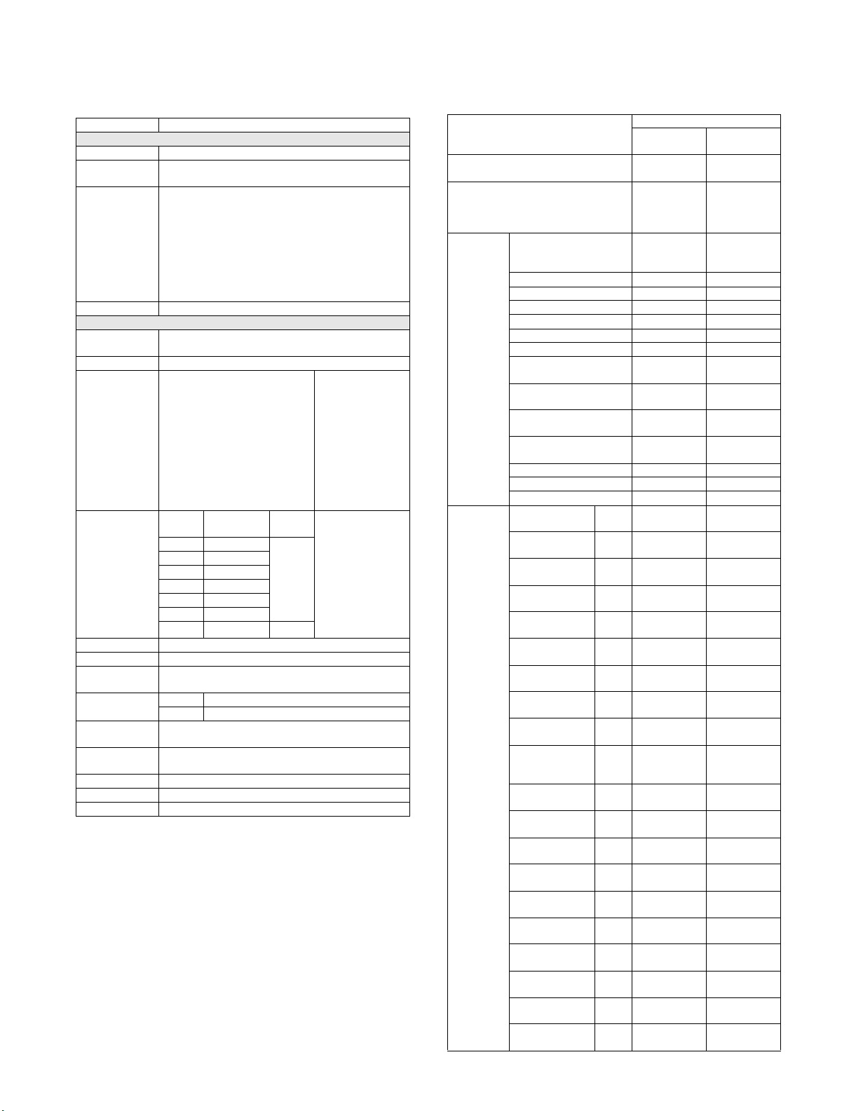
[1] SPECIFICATION
Service Manual
1. General
Form Floor type
Transport speed 85-110 sheets/minute (A4, 8.5"x11")
Transport
alignment
Paper Size
(Through pass)
Paper Weight 52g/m
Processing
performance
Folding Type Z-folding
Adjustment of
Folding Position
(1st time)
Adjustment of
Folding Position
(2nd time)
Paper size A3, B4, A4-R, 11"x17", 8.5"x14", 8.5"x11"-R
Paper weight 60-90g/m
Reversing
mechanism
Reliability MCBJ In compliance with the main unit.
Life Straight pass section: 5 years or 24,000K
Power
Consumption
Power Source 120W
Dimensions 177mm(W) x 634mm(D) x 980mm(H)
Weight 53.2kg or less
Through Pass Section
Center alignment
All papers that can be fed from the main unit or inserter.
A3W, A3, B4, A4, A4-R, B5, B5-R, A5, A5-R, 8K, 16K,
16KR, 12"x18", 11"x17", 9"x12", 8.5"x14" , 8.5"x13.4",
8.5"x13", 8.5"x11", 8.5"x11"-R, 5.5"x8.5", 5.5"x8.5"-R,
7.25"x10.5"R, SRA3 (320x450mm), SRA4,
318x234.75mm, 312.5x220mm, 318x469.5mm,
312.5x440mm, Postcard
* A5/5.5"x8.5" are fed from Inserter Tray of Inserter
Unit.
2
- 300g/m2,16lbs Bond-170lbs Index
50 sheets/minute (A4R, 8.5"x11"-R)
Available (±4mm), Adjustment
pitch 0.1mm, Controlled by the
main unit.
8.5x14 -4 - 33
8.5x11 Impossible ---
None
MCBF In compliance with the main unit.
(Folding section: 5 years or 6,000K)
AC100 - 240V (In-let type, Original cable)
Folding Section
Adjustment
Size
range (mm)
A3R -4 - 23 0.1mm
B4R -4 - 38
A4R -4 - 8
12x18 -4 - 3
11x17 -4 - 18
2
,16lbs-24lbs Bond
Pitch
When folding paper
in half, if you set +
value (default is 0
mm), edge of
paper which is
folding side moves
to outside, if you
set - value, edge of
paper which is
folding side moves
to inside.
When folding paper
to one-quarter, If
you set + value
(default is 2mm
inside), edge of
paper moves to
inside, If you set value, edge of
paper moves to
outside.
2. Paper Size/Type/Weight
Through
Minimum paper weight 52g/m
Maximum paper weight 300g/m
Paper type Thin paper Yes
Plain paper Yes Yes
Recycled paper Yes Yes
Colored paper Yes Yes
Letter head Yes Yes
Pre-printed paper Yes Yes
Pre-punched paper Yes Yes
Heavy paper1
(106-128g/m
Heavy paper2
(129-176g/m
Heavy paper3
(177-205g/m
Heavy paper4
(206-300g/m
Tab paper Yes No
Transparency paper Yes No
Label paper Yes No
Paper size 12"x18" (A3W) 305
Ledger (11"x17") 279
Ledger (11"x17")
Z folding
Legal (8.5"x14") 216
Legal (8.5"x14")
Z folding
Mexican Legal
(8.5"x13.4")
Foolscap
(8.5"x13")
Letter (8.5"x11") 279
Letter R
(8.5"x11"R)
Letter R
(8.5"x11"R)
Z folding
Invoice
(5.5"x8.5")
Invoice R
(5.5"x8.5"R)
Exective R
(7.25"x10.5")
9x12 (A4W) 305
A3 297
A3 Z folding 297
B4 257
B4 Z folding 257
A4 297
A4-R 210
2
)
2
)
2
)
2
)
pass section
(40lbs bond)
(140lbs index)
(100lbs cover)
(Even 52g/m
is possible)
x457
x432
279
x216
x356
216
x178
216
x340
216
x330
x216
216
x279
216
x140
216
x140
140
x216
184
x266
x229
x420
x210
x364
x182
x210
x297
Folding Unit
2
2
Ye s N o
Ye s N o
Ye s N o
Ye s N o
Ye s N o
Ye s Ye s
-Yes
Ye s Ye s
-Yes
Ye s N o
Ye s N o
Ye s N o
Ye s Ye s
-Yes
Ye s -
Ye s N o
Ye s N o
Ye s N o
Ye s Ye s
-Yes
Ye s Ye s
-Yes
Ye s N o
Ye s Ye s
2
Folding
section
60g/m2
(16lbs bond)
90g/m2
24lbs Bond
No
MX-FDX1 SPECIFICATION 1 – 1
Page 3
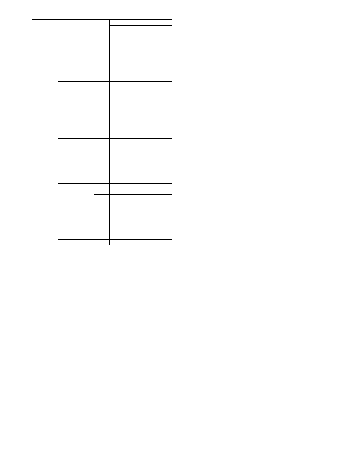
Paper size A4-R Z folding 210
x148
B5 257
x182
B5-R 182
x257
A5 210
x148
A5-R 148
x210
SRA3 320
x450
SRA4 320
x225
318x234.75mm Yes No
312.5x220mm Yes No
318x469.5mm Yes No
312.5x440mm Yes No
8K 270
x390
16K 270
x195
16K-R 195
x270
Postcard 100
x148
Special-Custom size Yes No
Folding Unit
Through
pass section
-Yes
Yes No
Yes No
Yes -
Yes No
Yes No
Yes No
Yes No
Yes No
Yes No
Yes No
Folding
section
(Custom Range) min
Main
max
Main
min
Sub
max
Sub
Special-Size uncertain Yes No
100 (4.0) -
320 (12.5) -
140 (5.5) -
470 (18.5) -
MX-FDX1 SPECIFICATION 1 – 2
Page 4

MX-FDX1
[2] MAINTENANCE LIST
✕: Check {: Clean S: Replace U: Adjust ✩: Lubricate : Shift position
(Clean, replace, or adjust as needed.)
Service Manual
No. Part name
1 Reflection type sensor ✕ {{{{{{ Clean by air
2 Sensor reflection plate ✕ {{{{{{ Clean by air
3 Folding roller ✕ {{{{{{Folding mode counter
4 Transport guide plate ✕ {{{{{{
5 Gear ✕✕✕✕✕✕✕ UKOG-0307FCZZ
When
calling
500K 1000K 1500K 2000K 2500K 3000K Life judgement (Reference)
every 200K
Tool, oil, chemicals
Procedure
Treatment after procedure
When there is dirt, wipe
with wet cloth and water.
MX-FDX1 MAINTENANCE LIST 2 – 1
Page 5
[A]
[B]
[C]
MX-FDX1
[3] REPLACEMENT AND ADJUSTMENT
Service Manual
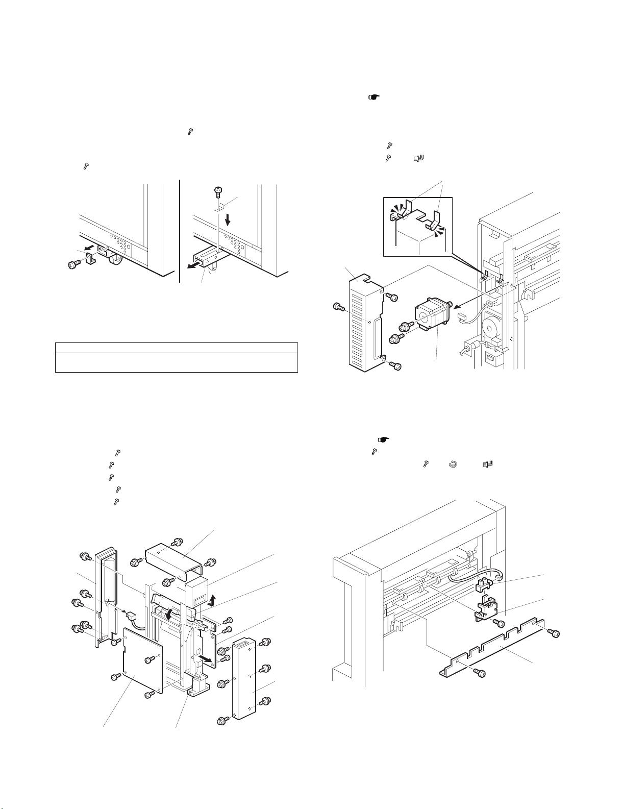
1. BEFORE YOU BEGIN
1) Disengage the Z-folding unit from the machine.
2) Disengage the Z-folding unit from the finisher (or cover sheet
feeder).
3) At the bottom on the sides of the Z-folding unit:
• Remove the lock bracket [A] ( x 1).
• Pull out the foot extension [B].
• Re-attach the bracket [A] to lock the foot in the open position
( x 1).
[A]
[A]
[B]
Reinstallation
Do this procedure in the opposite sequence to retract and lock the
extensions below the Z-folding unit.
CAUTION
The Z-folding unit is not stable, with or without the feet extended. Do your
work carefully; do not tilt the unit.
3. FEED MOTOR
• Pull the Z-folding mechanism out of the unit, but not fully.
Remove: ( 2. COVERS)
• Left cover
• Right cover
• Rear cover
[A] Motor cover ( x 3)
[B] Feed Motor ( x 2, x 1, timing belt x 1)
[C]
[A]
[B]
2. COVERS
• Open the front door [A].
• Lift the horizontal transport plate [B] to the left until it locks on the
left side.
• Pull out the Z-fold mechanism [C].
[D] Front cover ( x 6)
[E] Top cover ( x 4)
[F] Left cover ( x 4)
[G] Right cover ( x 5)
[H] Rear cover ( x 6)
[E]
[A]
[H]
[B]
[G]
[D]
Reinstallation
Confirm that the motor cover is below the leaf springs at [C].
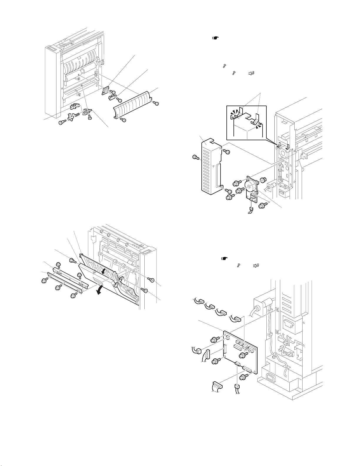
4. UPPER EXIT SENSOR
• Left cover ( 2. COVERS)
[A] Bracket ( x 2)
[B] Upper exit sensor unit ( x 1, x 1, x 1)
[C] Upper exit sensor
[F]
[C]
MX-FDX1 REPLACEMENT AND ADJUSTMENT 3 – 1
Page 6
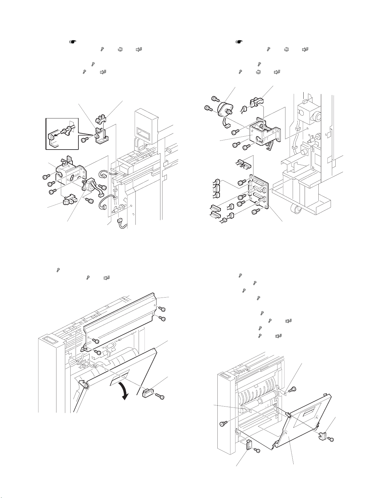
5. UPPER STOPPER MOTOR/HP
SENSOR, FEED SENSOR
• Front cover ( 2. COVERS)
[A] Upper stopper motor unit ( x 3, x 2, x 2)
[B] Upper stopper motor HP sensor
[C] Upper stopper motor ( x 2)
[D] Feed sensor unit ( x 1, x 1)
[E] Feed sensor
7. LOWER STOPPER MOTOR/HP SENSOR, RELAY BOARD
• Front cover ( 2. COVERS)
[A] Lower stopper motor unit ( x 3, x 2, x 2),
[B] Lower stopper HP sensor
[C] Lower stopper motor ( x 2)
[D] Relay board ( x 4, x 3, x 10)
[C]
[B]
[D]
[E]
[A]
[B]
[C]
6. FOLD TIMING SENSOR
• Pull the Z-fold mechanism out of the unit.
[A] Open the right vertical transport unit cover.
[B] Plate ( x 4)
[C] Fold timing sensor ( x 1, x 1)
[B]
[A]
[A]
[D]
8. LEADING EDGE SENSOR, LOWER EXIT SENSOR
• Pull out the Z-folding mechanism.
• Open the right vertical transport cover [E].
[A] Left link arm ( x 1)
[B] Left corner bracket ( x 1)
[C] Right link arm ( x 1)
[D] Right corner bracket ( x 1)
[E] Vertical transport cover.
[F] Lower fold roller cover ( x 2)
[G] Leading edge sensor unit ( x 1, x 1)
[H] Leading edge sensor ( x 1)
[I] Lower exit sensor unit ( x 1, x 1)
[J] Lower exit sensor
[C]
[A]
[B]
MX-FDX1 REPLACEMENT AND ADJUSTMENT 3 – 2
[C]
[D]
[E]
Page 7
[G]
[H]
10. FOLD ROLLER MOTOR
• Pull the Z-folding mechanism out of the unit, but not fully.
Remove: ( 2. COVERS)
• Left cover
• Right cover
• Rear cover
[A] Motor cover ( x 3)
[B] Fold roller motor ( x 4, x 1, timing belt x 1)
[J]
[I]
9. ANTI-STATIC BRUSH
• Pull out the Z-folding mechanism.
• Open the left vertical transport cover [A].
• Open the vertical transport assembly [B].
Remove:
[C] Left link screw
[D] Right link screw
[E] Link screw
[F] Bracket
[G] Anti-static brush
[B]
[A]
[C]
[F]
[G]
[F]
[C]
[A]
[B]
Reinstallation
Make sure that the motor cover is below the leaf springs [C].
11. MAIN CONTROL BOARD
Remove:
• Rear cover. ( 2. COVERS)
[A] Main control board ( x 4, x 8)
[D]
[E]
[A]
MX-FDX1 REPLACEMENT AND ADJUSTMENT 3 – 3
Page 8

12. PSU
• Open the front door.
• Pull the Z-fold mechanism out of the unit.
Remove:
• Left cover and right cover. ( 2. COVERS)
[A] Base top cover ( x 3).
[B] Base left cover ( x 2).
[C] Base right cover ( x 2).
• Make a mark at the positions of the connectors, then disconnect them.
NOTE:
These connectors do not have different colors. To help you
connect them again correctly, make marks on them.
[D] Power supply unit (PSU) ( x4, x 2).
• Pull the PSU out of the right side of the bottom.
[E] Power supply board ( x 6, x 3).
[A]
B. Z-FOLD ADJUSTMENT SCREWS
The adjustment of the 1st fold is done by turning an adjustment
screw linked to the paper stopper.
Pull out the Z-fold mechanism.
Open the right cover to see the adjustment screw located at [A].
This is the screw used to adjust the 1st fold.
[A]
[B]
[D]
[C]
13. UNEVEN FOLDING ADJUSTMENT
A. OVERVIEW
Printed Side (1 Side)
1st Fold
[E]
Open the left cover to see the screw located at [B].
This is the screw used to adjust the 2nd fold.
[B]
2nd Fold
This procedure describes how to correct uneven folding (D) in
paper folded with the Z-Fold unit. Before doing this procedure,
please note the names and positions of the 1st and 2nd Fold.
Section [5]-2 provides a full description of how Z-folding is done.
MX-FDX1 REPLACEMENT AND ADJUSTMENT 3 – 4
D
Page 9

C. Z-FOLD ADJUSTMENT PROCEDURE
(1) 1st Fold Adjustment
1) Print one A3 copy and send it through the Z-fold unit.
2) Open the 2nd fold (2).
3) Turn the paper over so the edge (3) is aligned with the crease
of the 2nd fold.
1
9) After the adjustment is completed, use a screw driver to hold
the screw in position, then retighten the nut you loosened in
Step 5). Do not turn the screw.
(2) 2nd Fold Adjustment
1) Print one A3 copy and send it through the Z-fold unit.
2) Open the folded sheet at the 1st fold (1) then lay it down flat.
3) Stand the sheet on its end so the edge (3) is up and the crease
of the 1st fold is facing out.
2
1
3
3
4) Open the right door and locate the screw that adjusts the 1st
fold (see previous page).
5) Use a phillips screwdriver to turn the screw [A] to the left to
loosen the nut.
• If the corner is over the right edge, turn the screw to the
right.
• If the corner is over the left edge, turn the screw to the left.
NOTE:
• The illustration above shows the corner over the right
edge.
• You can see the pointer [B] change position on the
notches of the adjustment scale as you turn the screw.
1
2
3
3
4) Open the left door and locate the screw that adjusts the 2nd
fold (see previous page).
5) Use a phillips screwdriver to turn the screw [A] to the left to
loosen the nut.
• If the corner is over the right edge, turn the screw to the
right.
• If the corner is over the left edge, turn the screw to the left.
NOTE:
• The illustration shows the corner over the right edge.
• You can see the pointer [B] change position on the
notches of the adjustment scale as you turn the screw.
[A]
[B]
6) Close the Z-Fold unit.
7) Do another test print.
8) If the 1st fold is still misaligned, repeat this procedure until the
alignment is correct.
MX-FDX1 REPLACEMENT AND ADJUSTMENT 3 – 5
[B]
[A]
Page 10

6) Close the Z-Fold unit.
X
X
X
7) Do another test print.
8) If the 1st fold is still misaligned, repeat this procedure until the
alignment is correct.
9) After the adjustment is completed, use a screw driver to hold
the screw in position, then retighten the nut you loosened in
Step 5). Do not turn the screw.
D. Z-FOLD ADJUSTMENT REFERENCE TABLE
(1) 1st Fold Adjustment
Turn screw right
Turn screw left
(2) 2nd Fold Adjustment
Turn screw right
NOTE:
A one-notch adjustment on the scale means the alignment is corrected by about 1 mm.
Turn screw left
MX-FDX1 REPLACEMENT AND ADJUSTMENT 3 – 6
Page 11

MX-FDX1
[4] SERVICE TABLES
Service Manual
Perform the folding position adjustment on the administrator adjustment menu of the system setting.
లˍ୬պ౾
(B)
(A)
లˎ୬պ౾
1) Press [SYSTEM SETTING] key on the operation panel and log
in as the administrator.
(Password: admin/default)
2) Press [Administrator Adjustment] key and select [Option
Adjustment] on the administrator adjustment menu.
4) Adjust the paper folding position.
Adjustment condition
First folding
position
Adjust the
length of (A).
When the adjustment value is increased, the folding
edge position is shifted to the upper edge from the
position of 1/2.
(Example) When the adjustment value is increased:
3) Select [Folding Unit] from the option adjustment menu.
Second folding
position
Adjust the
length of (B).
When the adjustment value is increased, the folding
edge position is shifted from the first folded position.
(Example) When the adjustment value is increased.
MX-FDX1 SERVICE TABLES 4 – 1
Page 12

MX-FDX1
[5] DETAILS
Service Manual
1. OVERVIEW
26
25
24
23
22
21
20
19
18
17
16
15
1
2
3
4
5
6
7
8
9
10
11
12
2. Z-FOLDING UNIT PAPER PATH
A. PAPER PATH WITH NO FOLDING
The feed rollers [1] feed the paper from the main machine into the
Z-folding unit.
If Z-folding was not used for the job, the sheet feeds above the
closed junction gate [2].
The upper exit sensor [3] detects the leading and trailing edge of
the unfolded sheet.
The upper exit rollers [4] feed the unfolded sheet out of the Z-folding unit and into the finisher.
[1]
[4]
[3]
[2]
14
1 Front Door Sensor 14 Grip Rollers
2 Junction Gate 15 Lower Stopper
3 Feed Rollers 16 Leading Edge Sensor
4 Feed Sensor 17 Vertical Feed Rollers - 1
5 Fold Timing Sensor 18 Anti-Static Brush
6 Pinch Idle Roller 19 1st Fold Roller
7 Upper Stopper 20 Vertical Feed Rollers - 2
8 Upper Stopper Path Sensor 21 Upper Stopper HP Sensor
9 3rd Fold Roller 22 Pinch Feed Roller
10 2nd Fold Roller 23 Vertical Feed Rollers - 3
11 Lower Stopper HP Sensor 24 Vertical Feed Rollers - 4
12 Lower Exit Rollers 25 Upper Exit Sensor
13 Lower Exit Sensor 26 Upper Exit Rollers
13
MX-FDX1 DETAILS 5 – 1
Page 13

B. PAPER PATH WITH Z-FOLDING
The feed rollers [1] feed the paper from the main machine into the
Z-folding unit.
The junction gate solenoid energizes and opens the junction gate
[2]. The junction gate sends the sheet down into the Z-folding paper
path.
The upper and lower stopper motors move the upper stopper [3]
and lower stopper [4] to the positions for the paper size that was
used for the job.
The feed sensor [5] detects the leading edge and trailing edge of
the sheet. The pinch idle roller solenoid (upper) pulls the pinch idle
roller [6] away from the pinch feed roller [7] and the paper can fall
between the pinch rollers.
The anti-static brush [8] removes static electricity from the sheet.
When the fold timing sensor [9] detects the trailing edge of the
sheet, it energizes the pinch idle roller solenoid (lower). This
pushes the pinch idle roller [6] against the opposite pinch feed roller
[7].
The lower stopper [10] stops the sheet and buckles it slightly
toward the nip [11] of the 1st and 2nd fold rollers.
[1]
[3]
[4]
[9]
[8]
[6]
[7]
[5]
[2]
[1]
[5]
[7]
[9]
[6]
[3]
[11]
[8]
[4]
The pinch feed roller [1] turns and feeds the sheet down against the
lower stopper [2]
At the correct time, the fold roller motor switches on and turns the:
• 1st fold roller [3]
• 2nd fold roller [4]
• 3rd fold roller [5]
The sheet continues to buckle until it feeds into the nip [6] of the 1st
and 2nd fold rollers. These two rollers fold the sheet.
The leading edge sensor [7] detects the leading edge of the sheet:
• When the leading edge goes by while the paper feeds down (to
the lower stopper).
• When the leading edge goes by again while the paper feeds up
into the nip of the 1st and 2nd fold rollers.
If the leading edge sensor does not detect the leading edge at the
correct time, this sensor signals a jam.
At the correct time, the pinch idle roller [8] is pulled away from the
pinch feed roller [9] by the pinch idle roller solenoid (upper).
[10]
[2]
The 1st fold roller [1] and 2nd fold roller [2] continue to turn. This
feeds the edge of the 1st fold up until it hits the upper stopper [3].
The sheet lifts the feeler of the upper stopper path sensor [4]. This
sensor:
• Detects when the sheet comes to the upper stopper path.
• Detects when the sheet goes out of the upper stopper path.
The upper stopper sensor detects a jam if it does not detect that the
sheet comes and goes at the correct times.
When the sheet feeds between the 1st and 2nd fold rollers, this
pushes the first fold against the upper stopper. The sheet buckles
down into the gap between the 2nd fold roller [5] and 3rd fold roller
[6]. The second fold is made when the sheet feeds between the
2nd and 3rd feed rollers.
[3]
[4]
[1]
[6]
[2]
[5]
MX-FDX1 DETAILS 5 – 2
Page 14

The 2nd and 3rd fold rollers [1] continue to turn and feed the sheet
1
2
3
9
4
10
11
12
13
5678
down.
The feeler of the upper stopper path sensor [2] falls and the sensor
detects that the sheet is gone. The fold rollers feed the folded sheet
to the lower exit rollers [3].
The lower exit sensor [4] detects the leading edge and trailing edge
of the sheet. If the trailing edge is not detected during the correct
time interval, the sensor detects a jam.
The grip rollers [5] feed the folded sheet to the four pairs of vertical
feed rollers [6].
The upper exit sensor [7] detects the leading edge and trailing edge
of each folded sheet. If the leading and trailing edge are not
detected during the correct time interval, this sensor detects a jam.
The upper exit rollers [8] feed the folded sheet into the finisher.
At the correct time:
• The upper stopper motor lifts the upper stopper [9] until the upper
stopper sensor [10] detects that the upper stopper is at its home
position. This stops the motor.
• The lower stopper motor lowers the lower stopper [11] until the
lower stopper sensor [12] detects that the lower stopper is at its
home position. This stops the motor.
[8]
[7]
[6]
[9]
[2]
[10]
3. DRIVE LAYOUT
1 Feed Motor
2 Feed Rollers
3 Fold Roller Motor
4 Lower Exit Rollers
5 Grip Rollers
6 3rd Fold Roller
7 2nd Fold Roller
8 1st Fold Roller
9 Vertical Feed Rollers - 1
10 Vertical Feed Rollers - 2
11 Vertical Feed Rollers - 3
12 Vertical Feed Rollers - 4
13 Upper Exit Rollers
[1]
[3]
[4]
[12]
[11]
[5]
MX-FDX1 DETAILS 5 – 3
Page 15

4. ELECTRICAL COMPONENTS
A. OVERVIEW
S7
M1
M2
S9
4
S4
3
S3
SOL1
S1
SOL3
SOL2
S2
M4
S8
S5
S6
1
B. ELECTRICAL COMPONENT SUMMARY
Motors
No. Name Description
M1
STPASS_M
M2
ZFLD_M
M3
ZLSTPP_M
M4
ZUSTPP_M
PCBs
No. Name Description
PCB1 Main Control Board Controls the operation of the Z-
PCB2 PSU Supplies the dc power for the Z-
PCB3 Surge Protector
PCB4 Interface Board Motors and sensor interface board.
Feed Motor Drives the feed rollers and exit
Fold Roller Motor Drives the 1st, 2nd, and 3rd fold
Lower Stopper
Motor
Upper Stopper
Motor
Board
rollers of the Z-folding unit.
rollers.
Raises and lowers the lower
stopper. It 1) Raises the upper
stopper to the proper position for the
size of the paper selected for the
job, and 2) Lowers the lower stopper
until the lower stopper sensor
detects that the lower stopper is at
its home position where it remains
until the start of the next job.
Lowers and raises the upper
stopper. It 1) Lowers the upper
stopper to the proper position for the
size of the paper selected for the
job, and 2) Raises the upper stopper
until the upper stopper sensor
detects that the upper stopper is at
its home position where it remains
until the start of the next job.
folding unit.
folding unit.
Fuse and surge protector board.
2
1 Interface Board
2 Power Supply Unit
3 Surge Protector Board
4 Main Control Board
M1 Feed Motor
M2 Fold Roller Motor
M3 Lower Stopper Motor
M4 Upper Stopper Motor
S1 Feed Sensor
S2 Fold Timing Sensor
S3 Front Door Sensor
S4 Leading Edge Sensor
S5 Lower Exit Sensor
S6 Lower Stopper HP Sensor
S7 Upper Exit Sensor
S8 Upper Stopper HP Sensor
S9 Upper Stopper Path Sensor
SOL1 Junction Gate Solenoid
SOL2 Pinch Idle Roller Solenoid - Lower
SOL3 Pinch Idle Roller Solenoid - Upper
M3
Sensors
No. Name Description
S1
ZFEED
S2
ZPRSTM
S3
UPDOOR
S4
ZPRTTM
Feed Sensor Detects the leading edge and trailing
Fold Timing Sensor (1) Detects the leading edge of the
Front Door Sensor Detects when the top cover of the Z-
Leading Edge
Sensor
edge of the sheet at the top of the
paper path before Z-Folding. When
the feed sensor detects the leading
edge, it energizes the pinch idle
roller solenoid. The solenoid pulls
the pinch idle roller away from the
pinch feed roller so the paper can
fall below these opposing rollers.
sheet and energizes the pinch idle
roller solenoid (upper) to pull the
pinch idle roller away from the pinch
feed roller so the sheet falls through
the gap between these rollers. (2)
Detects the trailing edge of the sheet
and energizes the pinch idle roller
solenoid (lower) to push the pinch
idle roller against the pinch feed
roller.
folding unit is closed and signals an
alert that the cover is open. The unit
cannot be used until this cover is
closed.
Mounted above the lower stopper.
The leading edge sensor 1) detects
the leading edge of the sheet when
drops onto the lower stopper, 2)
detects the leading edge again when
the paper is pulled up into the nip of
the 1st and 2nd fold rollers. If the
leading edge sensor does not detect
the edge at the prescribed times, it
will signal an error.
MX-FDX1 DETAILS 5 – 4
Page 16

Sensors
No. Name Description
S5
ZEXII1
S6
LSTPPRHP
S7
ZEXIT3
S8
HSTPPRHP
S9
HSTPPRPS
Lower Exit Sensor Mounted below the lower exit rollers.
Lower Stopper HP
Sensor
Upper Exit Sensor 1) Detects the leading/trailing edges
Upper Stopper HP
Sensor
Upper Stopper Path
Sensor
Detects the leading/trailing edges of
the folded sheet as it passes below.
If these edges do not pass at the
times prescribed for the selected
paper size, the sensor will signal a
jam alert.
Detects the lower stopper when it
reaches its home position and turns
off the lower stopper motor.
of each sheet unfolded sheet after it
passes over the closed junction
gate, 2) Detects the leading/trailing
edge of each folded sheet as it
leaves the vertical feed path below.
If the edges do not go by for the time
prescribed for the paper size, the
sensor will send a jam alert.
Detects the upper stopper when it
reaches its home position and turns
off the upper stopper motor.
Mounted below the upper stopper. 1)
When the feeler of the upper stopper
path sensor detects the paper when
the crease of the first fold stops at
the upper stopper, it delays long
enough so the 1st/2nd feed rollers
can continue to rotate and buckle
the trailing edge of the paper below
at the nip of the 2nd/3rd feed rollers,
then the sensor switches off the 1st/
2nd feed rollers and switches on the
2nd/3rd feed roller pair. The 2nd/3rd
feed rollers pull the buckle into the
nip and create the 2nd crease. 2)
Detects the paper when it leaves the
upper stopper path and signals an
error if the paper does not leave at
the prescribed time.
Solenoids
No. Name Description
SOL1
FLPPR_S
SOL2
ZPRES_S
SOL3
ZEST_S
Junction Gate
Solenoid
Pinch Idle Roller
Solenoid (Lower)
Pinch Idle Roller
Solenoid (Upper)
Opens and closes the junction gate
solenoid. When not energized, the
junction gate remains closed and
paper passes over the back of the
closed junction gate and through the
Z-folding unit. When energized it
opens the junction gate which
guides paper down and into the
paper path of the Z-folding unit.
Attached to the pinch idle roller, this
solenoid pushes the pinch idle roller
and closes the gap between the
pinch idle/pinch feed rollers when
the fold timing sensor at the above
the pinch idle roller detects the
trailing edge of the sheet so the
rollers can pinch and stop the paper
in the paper path.
Attached to the pinch idle roller, this
solenoid pulls the pinch idle roller
away from the pinch feed roller
when the feed sensor at the top of
the Z-fold paper path detects the
leading edge of the sheet so the
paper can drop between these
opposing rollers.
MX-FDX1 DETAILS 5 – 5
Page 17

C. BLOCK DIAGRAM
Straight pass
motor
F1
Folding motor
Upper stopper
motor
Lower stopper
motor
Flapper solenoid
Pressure solenoid
Separation solenoid
Drawer unit
Drawer connector
CP1 CP4
PBA-CONT PBA-CN
To LOGIC
DC5V
DC-DC CONVERTOR
FUZE1
CP3
CP2
CP5
CP1
DC24V
N
DC POWER SUPPLY
L
MX-FDX1 DETAILS 5 – 6
AC100V - 240V
PBA-SP
(AC FILTER)
N
F1 F2
L
AC INLET
AC100V - 240V
Page 18

D. ACTUAL WIRING CHART
Upper stopper motor
Paper feed motor
Lower stopper motor
Flapper solenoid
Paper exit sensor 1
Upper stopper
home position
sensor
Lower stopper
home position
sensor
Upper stopper
section pass
sensor
Paper feed
sensor
Paper exit
Z-folding motor
Pressure solenoid
Separation solenoid
sensor 3
Frame side Slide side
Pressure sensor
Complex cable
Power source
Separation sensor
Cover open/close
sensor
Main unit or
front stage unit
Main unit or
front stage unit
Rear stage unit
MX-FDX1 DETAILS 5 – 7
Page 19

y
LEAD-FREE SOLDER
The PWB’s of this model employs lead-free solder. The “LF” marks indicated on the PWB’s and the Service Manual mean “Lead-Free” solder.
The alphabet following the LF mark shows the kind of lead-free solder.
Example:
<Solder composition code of lead-free solder>
Solder composition
Sn-Ag-Cu
Sn-Ag-Bi
Sn-Ag-Bi-Cu
Sn-Zn-Bi
Sn-In-Ag-Bi
Sn-Cu-Ni
Sn-Ag-Sb
Bi-Sn-Ag-P
Bi-Sn-Ag
5mm
Lead-Free
Solder composition
code (Refer to the
table at the right.)
a
(1) NOTE FOR THE USE OF LEAD-FREE SOLDER THREAD
When repairing a lead-free solder PWB, use lead-free solder thread.
Never use conventional lead solder thread, which may cause a breakdown or an accident.
Since the melting point of lead-free solder thread is about 40°C higher than that of conventional lead solder thread, the use of the
exclusive-use soldering iron is recommended.
Solder composition code
a
b
z
i
n
s
p
(2) NOTE FOR SOLDERING WORK
Since the melting point of lead-free solder is about 220°C, which is about 40°C higher than that of conventional lead solder, and its soldering
capacity is inferior to conventional one, it is apt to keep the soldering iron in contact with the PWB for longer time. This may cause land
separation or may exceed the heat-resistive temperature of components. Use enough care to separate the soldering iron from the PWB when
completion of soldering is confirmed.
Since lead-free solder includes a greater quantity of tin, the iron tip may corrode easily. Turn ON/OFF the soldering iron power frequently.
If different-kind solder remains on the soldering iron tip, it is melted together with lead-free solder. To avoid this, clean the soldering iron
tip after completion of soldering work.
If the soldering iron tip is discolored black during soldering work, clean and file the tip with steel wool or a fine file.
COPYRIGHT©XXXX BYSHARP CORPORATION
COPYRIGHT©XXXX BYSHARP CORPORATION
ALL RIGHTS RESERVED.
ALL RIGHTS RESERVED.
No part of this publication may be reproduced,
No part of this publication may be reproduced,
stored in a retrieval system, or transmitted in
stored in a retrieval system, or transmitted in
any form or by any means, electronic, mechanical,
form or byanymeans, electronic, mechanical,
an
photocopying, recording, or otherwise, without
prior written permission of the publisher.
Page 20

CAUTION FOR BATTERY REPLACEMENT
(Danish) ADVARSEL !
Lithiumbatteri – Eksplosionsfare ved fejlagtig håndtering.
(English) Caution !
Dispose of used batteries according to manufacturer’s instructions.
(Finnish) VAROITUS
Paristo voi räjähtää, jos se on virheellisesti asennettu.
Vaihda paristo ainoastaan laitevalmistajan suosittelemaan
(French) ATTENTION
Il y a danger d’explosion s’ il y a remplacement incorrect
de la batterie. Remplacer uniquement avec une batterie du
même type ou d’un type équivalent recommandé par
Mettre au rebut les batteries usagées conformément aux
(Swedish) VARNING
(German) Achtung
Explosionsgefahr bei Verwendung inkorrekter Batterien.
Als Ersatzbatterien dürfen nur Batterien vom gleichen Typ oder
vom Hersteller empfohlene Batterien verwendet werden.
Entsorgung der gebrauchten Batterien nur nach den vom
Udskiftning må kun ske med batteri
af samme fabrikat og type.
Levér det brugte batteri tilbage til leverandoren.
Danger of explosion if battery is incorrectly replaced.
Replace only with the same or equivalent type
recommended by the manufacturer.
tyyppiin. Hävitä käytetty paristo valmistajan ohjeiden
mukaisesti.
le constructeur.
instructions du fabricant.
Explosionsfara vid felaktigt batteribyte.
Använd samma batterityp eller en ekvivalent
typ som rekommenderas av apparattillverkaren.
Kassera använt batteri enligt fabrikantens
instruktion.
Hersteller angegebenen Anweisungen.
CAUTION FOR BATTERY DISPOSAL
(For USA, CANADA)
THIS PRODUCT CONTAINS A LITHIUM PRIMARY
(MANGANESS DIOXIDE) MEMORY BACK-UP BATTERY
THAT MUST BE DISPOSED OF PROPERLY. REMOVE THE
BATTERY FROM THE PRODUCT AND CONTACT YOUR
LOCAL ENVIRONMENTAL AGENCIES FOR INFORMATION
ON RECYCLING AND DISPOSAL OPTIONS.
CE PRODUIT CONTIENT UNE PILE DE SAUVEGARDE DE
MÉMOIRE LITHIUM PRIMAIRE (DIOXYDE DE MANGANÈSE)
QUI DOIT ÊTRE TRAITÉE CORRECTEMENT. ENLEVEZ LA
PILE DU PRODUIT ET PRENEZ CONTACT AVEC VOTRE
AGENCE ENVIRONNEMENTALE LOCALE POUR DES
INFORMATIONS SUR LES MÉTHODES DE RECYCLAGE ET
“BATTERY DISPOSAL”
“TRAITEMENT DES PILES USAGÉES”
DE TRAITEMENT.
Page 21

COPYRIGHT 2007 BY SHARP CORPORATION
All rights reserved.
Printed in Japan.
No part of this publication may be reproduced,
stored in a retrieval system, or transmitted,
in any form or by any means,
electronic; mechanical; photocopying; recording or otherwise
without prior written permission of the publisher.
Trademark acknowledgements
Microsoft
Corporation in the U. S.A. and other countries.
Windows
Windows®
and
U.S.A. and other countries.
IBM and PC/AT are trademarks of International Business Machines Corporation.
Acrobat
reserved. Adobe, the Adobe logo, Acrobat, and the Acrobat logo are trademarks
of Adobe Systems Incorporated.
All other trademarks and copyrights are the property of their respective owners.
®
Windows® operating system is a trademark or copyright of Microsoft
®
95, Windows®
XP, Windows®
Internet Explorer®
®
Reader Copyright® 1987-2002 Adobe Systems Incorporated. All rights
98, Windows® Me, Windows NT®
Vista, Windows®
2000 Server, Windows®
4.0, Windows® 2000,
are trademarks or copyrights of Microsoft Corporation
Server 2003
in the
SHARP CORPORATION
Digital Document System Group
CS Promotion Center
Yamatokoriyama, Nara 639-1186, Japan
2007 May Printed in Japan
 Loading...