

Page 1
TopPage
SERVICE MANUAL
CODE: 00ZMXB402/S1E
DIGITAL MULTIFUNCTIONAL
SYSTEM
MX-B382
MODEL
CONTENTS
NOTE FOR SERVICING
[1] PRODUCT OUTLINE . . . . . . . . . . . . . . . . . . . . . . . . . . . . . . . . . . . . . . . . . . . . . . . 1-1
[2] CONSUMABLE PARTS . . . . . . . . . . . . . . . . . . . . . . . . . . . . . . . . . . . . . . . . . . . . . 2-1
[3] EXTERNAL VIEW AND INTERNAL STRUCTURE . . . . . . . . . . . . . . . . . . . . . . . . 3-1
[4] ADJUSTMENTS . . . . . . . . . . . . . . . . . . . . . . . . . . . . . . . . . . . . . . . . . . . . . . . . . . . 4-1
[5] SIMULATION . . . . . . . . . . . . . . . . . . . . . . . . . . . . . . . . . . . . . . . . . . . . . . . . . . . . . 5-1
[6] SELF DIAG AND TROUBLE CODE . . . . . . . . . . . . . . . . . . . . . . . . . . . . . . . . . . . . 6-1
[7] FIRMWARE UPDATE . . . . . . . . . . . . . . . . . . . . . . . . . . . . . . . . . . . . . . . . . . . . . . . 7-1
[8] OPERATIONAL DESCRIPTIONS. . . . . . . . . . . . . . . . . . . . . . . . . . . . . . . . . . . . . . 8-1
[9] MAINTENANCE . . . . . . . . . . . . . . . . . . . . . . . . . . . . . . . . . . . . . . . . . . . . . . . . . . . 9-1
[10] DISASSEMBLY AND ASSEMBLY . . . . . . . . . . . . . . . . . . . . . . . . . . . . . . . . . . . . 10-1
MX-B402
[11] VARIOUS STORAGE DATA HANDLING . . . . . . . . . . . . . . . . . . . . . . . . . . . . . . . 11-1
[12] SERVICE WEB PAGE . . . . . . . . . . . . . . . . . . . . . . . . . . . . . . . . . . . . . . . . . . . . . 12-1
[13] SPECIFICATIONS . . . . . . . . . . . . . . . . . . . . . . . . . . . . . . . . . . . . . . . . . . . . . . . . 13-1
[14] SIGNAL LIST . . . . . . . . . . . . . . . . . . . . . . . . . . . . . . . . . . . . . . . . . . . . . . . . . . . . 14-1
[15] ACTUAL WIRING DIAGRAM . . . . . . . . . . . . . . . . . . . . . . . . . . . . . . . . . . . . . . . . 15-1
Parts marked with " " are important for maintaining the safety of the set. Be sure to replace these parts with
specified ones for maintaining the safety and performance of the set.
This document has been published to be used
SHARP CORPORATION
for after sales service only.
The contents are subject to change without notice.
Page 2

CONTENTS
NOTE FOR SERVICING
1. Precautions for servicing . . . . . . . . . . . . . . . . . . . . . . . . . i
2. Warning for servicing . . . . . . . . . . . . . . . . . . . . . . . . . . . . i
3. Note for installing site. . . . . . . . . . . . . . . . . . . . . . . . . . . . i
4. Note for handling PWB and electronic parts . . . . . . . . . .ii
5. Note for repairing/replacing the LSU . . . . . . . . . . . . . . . iii
6. Note for handling the drum cartridge, the transfer unit,
the developer cartridge, and the fusing unit . . . . . . . . . . iii
[1] PRODUCT OUTLINE
1. System configuration . . . . . . . . . . . . . . . . . . . . . . . . . . 1-1
2. Machine configuration . . . . . . . . . . . . . . . . . . . . . . . . . 1-2
3. Option list. . . . . . . . . . . . . . . . . . . . . . . . . . . . . . . . . . . 1-2
[2] CONSUMABLE PARTS
1. Supply system table . . . . . . . . . . . . . . . . . . . . . . . . . . . 2-1
2. Maintenance parts list . . . . . . . . . . . . . . . . . . . . . . . . . 2-1
3. Production number identification . . . . . . . . . . . . . . . . . 2-3
4. Life end conditions. . . . . . . . . . . . . . . . . . . . . . . . . . . . 2-3
5. Life end display . . . . . . . . . . . . . . . . . . . . . . . . . . . . . . 2-4
6. Environment conditions . . . . . . . . . . . . . . . . . . . . . . . .2-5
[3] EXTERNAL VIEW AND INTERNAL STRUCTURE
1. External view . . . . . . . . . . . . . . . . . . . . . . . . . . . . . . . . 3-1
2. Internal structure . . . . . . . . . . . . . . . . . . . . . . . . . . . . . 3-2
3. RSPF . . . . . . . . . . . . . . . . . . . . . . . . . . . . . . . . . . . . . . 3-3
4. Connectors. . . . . . . . . . . . . . . . . . . . . . . . . . . . . . . . . . 3-3
5. Operation panel . . . . . . . . . . . . . . . . . . . . . . . . . . . . . . 3-4
6. Sensors and detectors . . . . . . . . . . . . . . . . . . . . . . . . . 3-5
7. Switches. . . . . . . . . . . . . . . . . . . . . . . . . . . . . . . . . . . . 3-6
8. Clutches and solenoids . . . . . . . . . . . . . . . . . . . . . . . . 3-7
9. Drive motors. . . . . . . . . . . . . . . . . . . . . . . . . . . . . . . . . 3-8
10. Lamps . . . . . . . . . . . . . . . . . . . . . . . . . . . . . . . . . . . . . 3-9
11. Fans and filter . . . . . . . . . . . . . . . . . . . . . . . . . . . . . . 3-10
12. PWB . . . . . . . . . . . . . . . . . . . . . . . . . . . . . . . . . . . . . . 3-11
13. Fuses and Thermostats . . . . . . . . . . . . . . . . . . . . . . . 3-12
14. Gates . . . . . . . . . . . . . . . . . . . . . . . . . . . . . . . . . . . . . 3-13
15. Rollers . . . . . . . . . . . . . . . . . . . . . . . . . . . . . . . . . . . . 3-14
[4] ADJUSTMENTS
1. General . . . . . . . . . . . . . . . . . . . . . . . . . . . . . . . . . . . . 4-1
2. Adjustment item list . . . . . . . . . . . . . . . . . . . . . . . . . . . 4-1
3. Details of adjustment . . . . . . . . . . . . . . . . . . . . . . . . . . 4-2
[5] SIMULATION
1. General (Including basic operations) . . . . . . . . . . . . . . 5-1
2. List of simulation codes . . . . . . . . . . . . . . . . . . . . . . . . 5-3
3. Details of simulation . . . . . . . . . . . . . . . . . . . . . . . . . . . 5-7
[6] SELF DIAG AND TROUBLE CODE
1. Self diag. . . . . . . . . . . . . . . . . . . . . . . . . . . . . . . . . . . . 6-1
2. Trouble code list. . . . . . . . . . . . . . . . . . . . . . . . . . . . . . 6-4
3. Details of trouble code . . . . . . . . . . . . . . . . . . . . . . . . . 6-6
[7] FIRMWARE UPDATE
1. Outline . . . . . . . . . . . . . . . . . . . . . . . . . . . . . . . . . . . . . 7-1
2. Update procedure . . . . . . . . . . . . . . . . . . . . . . . . . . . .7-1
[8] OPERATIONAL DESCRIPTIONS
1. Operation panel . . . . . . . . . . . . . . . . . . . . . . . . . . . . . . 8-1
2. Scanner section . . . . . . . . . . . . . . . . . . . . . . . . . . . . . . 8-2
3. Manual paper feed section. . . . . . . . . . . . . . . . . . . . . . 8-4
4. Paper feed tray section . . . . . . . . . . . . . . . . . . . . . . . . 8-6
5. Paper transport and switchback section . . . . . . . . . . . 8-9
6. LSU section . . . . . . . . . . . . . . . . . . . . . . . . . . . . . . . . 8-11
7. Photo-conductor section . . . . . . . . . . . . . . . . . . . . . . 8-14
8. Toner supply section . . . . . . . . . . . . . . . . . . . . . . . . . 8-18
9. Developing section. . . . . . . . . . . . . . . . . . . . . . . . . . . 8-19
10. Transfer section . . . . . . . . . . . . . . . . . . . . . . . . . . . . .8-20
11. Fusing section . . . . . . . . . . . . . . . . . . . . . . . . . . . . . . 8-24
12. Paper exit section. . . . . . . . . . . . . . . . . . . . . . . . . . . . 8-26
13. Process control sensor,
image registration sensor section . . . . . . . . . . . . . . . 8-27
14. Automatic document feeder . . . . . . . . . . . . . . . . . . . . 8-28
15. Electrical section . . . . . . . . . . . . . . . . . . . . . . . . . . . .8-30
[9] MAINTENANCE
1. Necessary work for maintenance . . . . . . . . . . . . . . . . . 9-1
2. Maintenance timing display . . . . . . . . . . . . . . . . . . . . . 9-1
3. Maintenance list . . . . . . . . . . . . . . . . . . . . . . . . . . . . . . 9-4
[10] DISASSEMBLY AND ASSEMBLY
1. Exterior. . . . . . . . . . . . . . . . . . . . . . . . . . . . . . . . . . . . 10-1
2. Operation panel section . . . . . . . . . . . . . . . . . . . . . . . 10-4
3. Scanner section . . . . . . . . . . . . . . . . . . . . . . . . . . . . . 10-6
4. Manual paper feed section. . . . . . . . . . . . . . . . . . . . . 10-8
5. Tray paper feed section . . . . . . . . . . . . . . . . . . . . . . 10-11
6. Paper transport, switchback section . . . . . . . . . . . . 10-14
7. LSU section . . . . . . . . . . . . . . . . . . . . . . . . . . . . . . . 10-17
8. OPC drum section . . . . . . . . . . . . . . . . . . . . . . . . . . 10-18
9. Toner supply section . . . . . . . . . . . . . . . . . . . . . . . . 10-20
10. Developing section. . . . . . . . . . . . . . . . . . . . . . . . . . 10-21
11. Transfer section . . . . . . . . . . . . . . . . . . . . . . . . . . . . 10-25
12. Fusing section . . . . . . . . . . . . . . . . . . . . . . . . . . . . . 10-31
13. Paper exit section. . . . . . . . . . . . . . . . . . . . . . . . . . . 10-35
14. Drive section . . . . . . . . . . . . . . . . . . . . . . . . . . . . . . 10-37
15. PWB . . . . . . . . . . . . . . . . . . . . . . . . . . . . . . . . . . . . . 10-44
16. Fan . . . . . . . . . . . . . . . . . . . . . . . . . . . . . . . . . . . . . . 10-49
17. Filter . . . . . . . . . . . . . . . . . . . . . . . . . . . . . . . . . . . . .10-51
18. Process control sensor, registration sensor . . . . . . .10-51
19. Document feed unit . . . . . . . . . . . . . . . . . . . . . . . . . 10-53
20. Other . . . . . . . . . . . . . . . . . . . . . . . . . . . . . . . . . . . . 10-56
[11] VARIOUS STORAGE DATA HANDLING
1. Necessary works when replacing the PWB
and the HDD . . . . . . . . . . . . . . . . . . . . . . . . . . . . . . . 11-1
[12] SERVICE WEB PAGE
1. General . . . . . . . . . . . . . . . . . . . . . . . . . . . . . . . . . . . 12-1
2. Details and operation procedures . . . . . . . . . . . . . . . 12-1
[13] SPECIFICATIONS
1. Basic specifications . . . . . . . . . . . . . . . . . . . . . . . . . .13-1
[14] SIGNAL LIST . . . . . . . . . . . . . . . . . . . . . . . . . . . . . . . . . . 14-1
[15] ACTUAL WIRING DIAGRAM
1. Image process (MFPC, LSU) . . . . . . . . . . . . . . . . . . . 15-1
2. Scanner, Operation section (8.5) . . . . . . . . . . . . . . . . 15-2
3. Paper feed transport, Process drive, Front,
High voltage . . . . . . . . . . . . . . . . . . . . . . . . . . . . . . . . 15-3
4. Right door, Frame fusing . . . . . . . . . . . . . . . . . . . . . . 15-4
5. Process, DV, RESI, Paper exit . . . . . . . . . . . . . . . . . . 15-5
6. Power source, Frame electrical fitting, Option . . . . . . 15-6
7. AC, Fusing . . . . . . . . . . . . . . . . . . . . . . . . . . . . . . . . . 15-7
Page 3
MX-B402
NOTE FOR SERVICING
1. Precautions for servicing
1) When servicing, disconnect the power plug, the printer cable,
the network cable, and the telephone line from the machine,
except when performing the communication test, etc.
It may cause an injury or an electric shock.
2) There is a high temperature area inside the machine. Use an
extreme care when servicing.
It may cause a burn.
3) There is a high voltage section inside the machine which may
cause an electric shock. Be careful when servicing.
4) Do not disassemble the laser unit. Do not insert a reflective
material such as a screwdriver in the laser beam path.
It may damage eyes by reflection of laser beams.
5) When servicing with the machine operating, be careful not to
squeeze you hands by the belt, the gear, and other driving sections.
6) Do not leave the machine with the cabinet disassembled.
Do not allow any person other than a serviceman to touch
inside the machine. It may cause an electric shock, a burn, or
an injury.
7) When servicing, do not breathe toner, developer, and ink
excessively. Do not get them in the eyes.
If toner, developer, or ink enters your eyes, wash it away with
water immediately, and consult a doctor if necessary.
8) The machine has got sharp edges inside. Be careful not to
damage fingers when servicing.
9) Do not throw toner or a toner cartridge in a fire. Otherwise,
toner may pop and burn you.
10) When replacing the lithium battery of the PWB, use a specified
one only.
If a battery of different specification is used, it may be broken,
causing breakdown or malfunction of the machine.
11) When carrying a unit with PWB or electronic parts installed to
it, be sure to put it in an anti-static-electricity bag.
It may cause a breakdown or malfunctions.
4) When connecting the grounding wire, never connect it to the
Service Manual
following points.
It may cause an explosion, a fire or an electric shock.
• Gas tube
• Lightning conductor
• A water pipe or a water faucet, which is not recognized as a
grounding object by the authorities.
• Grounding wire for telephone line
5) Do not damage, break, or work the power cord.
Do not put heavy objects on the power cable. Do not bend it
forcibly or do not pull it extremely.
It may cause a fire or an electric shock.
6) Keep the power cable away from a heat source.
Do not insert the power plug with dust on it into a power outlet.
It may cause a fire or an electric shock.
7) Do not put a receptacle with water in it or a metal piece which
may drop inside the machine.
It may cause a fire or an electric shock.
8) With wet or oily hands, do not touch the power plug, do not
insert the telephone line jack, do not operate the machine, or
do not perform servicing.
It may cause an electric shock.
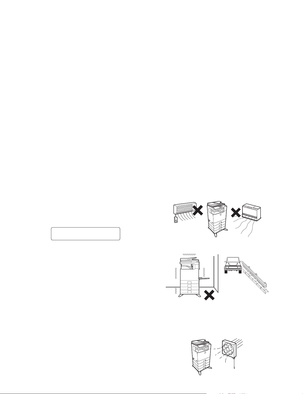
3. Note for installing site
Do not install the machine at the following sites.
1) Place of high temperature, high humidity, low tempera-
ture, low humidity, place under an extreme change in temperature and humidity.
Paper may get damp and form dews inside the machine, causing paper jam or copy dirt.
For operating and storing conditions, refer to the specifications
described later.
CAUTION
DOUBLE POLE/NEUTRAL FUSING
(200V series only)
2. Warning for servicing
1) Be sure to connect the power cord only to a power outlet that
meets the specified voltage and current requirements.
Avoid complex wiring, which may lead to a fire or an electric
shock.
It may cause a fire or an electric shock.
2) If there is any abnormality such as a smoke or an abnormal
smell, interrupt the job and disconnect the power plug.
It may cause a fire or an electric shock.
3) Be sure to connect the grounding wire. If an electric leakage
occurs without grounding, a fire or an electric shock may
result.
To protect the machine and the power unit from lightening,
grounding must be made.
2) Place of much vibrations
It may cause a breakdown.
3) Poorly ventilated place
An electrostatic type copier will produce ozone inside it.
The quantity of ozone produced is designed to a low level so
as not to affect human bodies. However, continuous use of
such a machine may produce a smell of ozone. Install the
machine in a well ventilated place, and ventilate occasionally.
MX-B382/B402 NOTE FOR SERVICING - i
Page 4
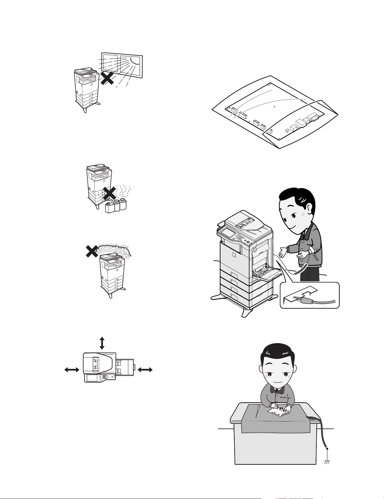
4) Place of direct sunlight.
Plastic parts and ink may be deformed, discolored, or may
undergo qualitative change.
It may cause a breakdown or copy dirt.
5) Place which is full of organic gases such as ammonium
The organic photo-conductor (OPC) drum used in the machine
may undergo qualitative change due to organic gases such as
ammonium.
Installation of this machine near a diazo-type copier may result
in dirt copy.
4. Note for handling PWB and electronic
parts
When handling the PWB and the electronic parts, be sure to
observe the following precautions in order to prevent against damage by static electricity.
1) When in transit or storing, put the parts in an anti-static bag or
an anti-static case and do not touch them with bare hands.
2) When and after removing the parts from an anti-static bag
(case), use an earth band as shown below:
• Put an earth band to your arm, and connect it to the
machine.
6) Place of much dust
When dusts enter the machine, it may cause a breakdown or
dirty copy.
7) Place near a wall
The machine will require intake and exhaust of air.
If intake and exhaust of air are not properly performed, dirty
copy or a breakdown may be resulted.
11-13/16"
(30cm)
11-13/16"
(30cm)
8) Unstable or irregular surface
If the machine drops or fall down, it may cause an injury or a
breakdown.
If there are optional paper desk and the copier desk specified,
it is recommendable to use them.
When using the optional desk, be sure to fix the adjuster and
lock the casters.
17-23/32"
(45cm)
• When repairing or replacing an electronic part, perform the
procedure on an anti-static mat.
MX-B382/B402 NOTE FOR SERVICING - ii
Page 5

5. Note for repairing/replacing the LSU
When repairing or replacing, be sure to observe the following
items.
1) When repairing or replacing the LSU, be sure to disconnect
the power plug from the power outlet.
2) When repairing or replacing the LSU, follow the procedures
described in this Service Manual.
3) When checking the operations after repairing the LSU, keep all
the parts including the cover installed and perform the operation check.
4) Do not modify the LSU.
5) When visually checking the inside of the machine for the operation check, be careful not to allow laser beams to enter the
eyes.
If the above precaution is neglected or an undesignated work is
performed, safety may not be assured.
6. Note for handling the drum cartridge, the
transfer unit, the developer cartridge, and
the fusing unit
When handling the OPC drum unit, the transfer unit, and the developer unit, strictly observe the following items.
If these items are neglected, a trouble may be generated in the
copy and print image quality.
(Drum cartridge)
1) Avoid working at a place with strong lights.
2) Do not expose the OPC drum to lights including interior lights
for a long time.
3) When the OPC drum is removed from the machine, cover it
with light blocking material. (When using paper, use about 10
sheets of paper to cover it.)
4) Be careful not to attach fingerprints, oil, grease, or other foreign material on the OPC drum surface.
(Transfer unit)
1) Be careful not to attach fingerprints, oil, grease, or other foreign material on the transfer belt and the transfer roller.
(Developer cartridge)
1) Be careful not to attach fingerprints, oil, grease, or other foreign material on the developer unit.
(Fusing unit)
1) Be careful not to put fingerprints, oil, grease, or other foreign
material on the fusing roller and the external heating belt.
2) Do not leave the fusing roller in contact state for a long time.
MX-B382/B402 NOTE FOR SERVICING - iii
Page 6
MX-B402
[1] PRODUCT OUTLINE
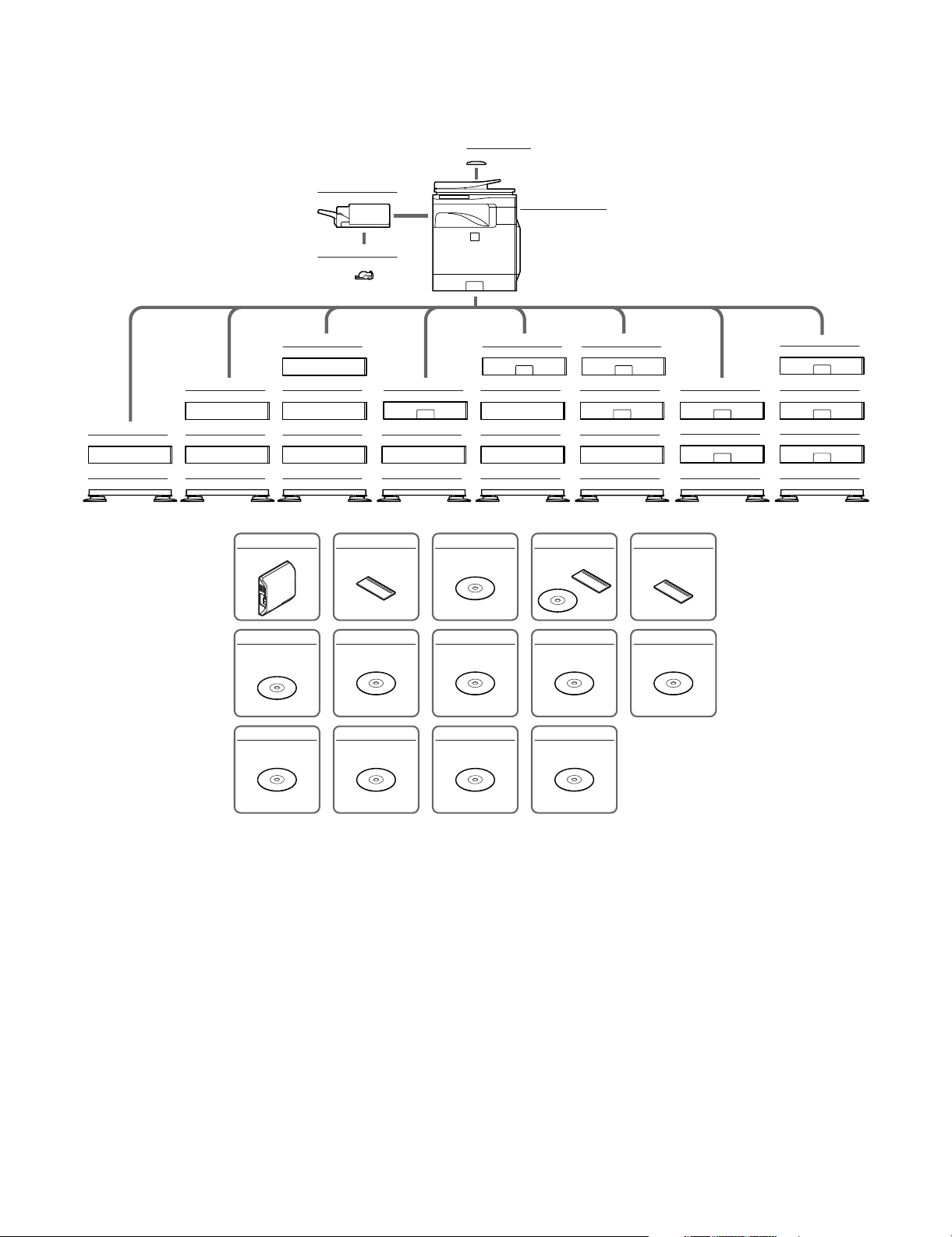
1. System configuration
MX-FN12
Finisher
MX-SCX1
Staple cartridge
Service Manual
MX-BTX1
Business card feeder
MX-B382/B402
Digital multifunctional system
MX-DS14
Additional stand
MX-DS13
Base stand
MX-DS14
Additional stand
MX-DS14
Additional stand
MX-DS13
Base stand
MX-DS14
Additional stand
MX-DS14
Additional stand
MX-DS14
Additional stand
MX-DS13
Base stand
MX-FXX3
Facsimile expansion kit
MX-AMX1
Application integration
module
MX-US10
Sharpdesk 10 license kit
MX-CSX1
500-sheet paper feed unit
MX-DS14
Additional stand
MX-DS13
Base stand
MX-SMX3
Expansion memory board
MX-AMX2
Application communication
module
MX-US50
Sharpdesk 50 license kit
MX-CSX1
500-sheet paper feed unit
MX-DS14
Additional stand
MX-DS14
Additional stand
MX-DS13
Base stand
MX-FWX1
Internet fax expansion kit
MX-AMX3
External account module
MX-USA0
Sharpdesk 100 license kit
MX-CSX1
500-sheet paper feed unit
MX-CSX2
500-sheet paper feed unit
MX-DS14
Additional stand
MX-DS13
Base stand
AR-PF1
Barcode font kit
MX-USX1
Sharpdesk 1 license kit
MX-PUX1
XPS expansion kit
MX-CSX1
500-sheet paper feed unit
MX-CSX2
500-sheet paper feed unit
MX-DS13
Base stand
MX-FR26U
Data security kit
(Commercial version)
MX-USX5
Sharpdesk 5 license kit
MX-CSX1
500-sheet paper feed unit
MX-CSX2
500-sheet paper feed unit
MX-CSX2
500-sheet paper feed unit
MX-DS13
Low stand
MX-B382/B402 PRODUCT OUTLINE 1 – 1
Page 7
2. Machine configuration
Main body LCD 7.0 Inch color LCD
RSPF STD
Automatic duplex STD
HDD STD
System memory 512MB
Local memory 512MB
Copier STD
PCL printer STD
PS printer STD
FAX OPT
Internet Fax OPT*
Network scanner STD
Filing STD
Security OPT*
OSA Expansion enable
1
1
STD: Standard provision, OPT: Option
*1: Product key target
3. Option list
Model Name Model name MX-B382/B402 Product key target
Paper feed system 500-sheet paper feed unit MX-CSX1 OPT –
Paper exit system Finisher MX-FN12 OPT –
Electrical system (ROM) Barcode font kit AR-PF1 OPT –
Electrical system (Software) Internet fax expansion kit MX-FWX1 OPT Yes
Memory Expansion memory board MX-SMX3 OPT*
STD: Standard provision, OPT: Option, –: No setting
*1: To install the MX-PUX1, the MX-SMX3 is required.
*2: No support for some destinations.
*3: This is required in case of short in the memory capacity due to print data. When the XPS expansion kit is installed, it is required.
500-sheet paper feed unit MX-CSX2 OPT –
Base stand MX-DS13 OPT –
Additional stand MX-DS14 OPT –
Data security kit MX-FR26U OPT Yes
XPS expansion kit MX-PUX1 OPT*
Sharpdesk 1 license kit MX-USX1 OPT –
Sharpdesk 5 license kit MX-USX5 OPT –
Sharpdesk 10 license kit MX-US10 OPT –
Sharpdesk 50 license kit MX-US50 OPT –
Sharpdesk 100 license kit MX-USA0 OPT –
Application integration module MX-AMX1 OPT Yes
Application communication module MX-AMX2 OPT Yes
External account module MX-AMX3 OPT Yes
Facsimile expansion kit MX-FXX3 OPT*
1
2
3
Yes
–
–
MX-B382/B402 PRODUCT OUTLINE 1 – 2
Page 8
MX-B402
[2] CONSUMABLE PARTS
1. Supply system table
A. USA/Canada/South and Central America
Service Manual
No. Item Content Life Model Name
1 Toner Cartridge Toner Cartridge with IC Chip (Toner : Net 430g) x 1 20K *1 MX-B42NT1 10
2 Developer Developer : Net 185g x 1 72K *2 MX-B42NV1 10
3 Drum Cartridge Drum Cartridge
Charger Cleaner
x 1
72K *2 MX-C40NRB 10
x 1
collective package
*1: Life: A4/Letter size at Area Coverage 5% (Reference: 16K for A4/Letter 6%)
The toner life may vary depending on the document density and temperature and humidity.
*2: 72K sheets or 550K rotations (For details, refer to item 4, "Life end conditions.")
The life of the above Developer Cartridge and the Drum Cartridge is 72K only when they are installed to the MX-B402.
B. Europe/Australia/New Zealand
No. Item Content Life Model Name
1 Toner Cartridge Toner Cartridge with IC Chip (Toner : Net 430g) x 1 20K *1 MX-B42GT1 10
2 Developer Developer : Net 185g x 1 72K *2 MX-B42GV1 10
3 Drum Cartridge Drum Cartridge
Charger Cleaner
x 1
72K *2 MX-C38GRB 10
x 1
*1: Life: A4/Letter size at Area Coverage 5% (Reference: 16K for A4/Letter 6%)
The toner life may vary depending on the document density and temperature and humidity.
*2: 72K sheets or 550K rotations (For details, refer to item 4, "Life end conditions.")
The life of the above Developer Cartridge and the Drum Cartridge is 72K only when they are installed to the MX-B382.
collective package
2. Maintenance parts list
Quantity in
Quantity in
Remarks
Remarks
A. USA/Canada/South and Central America
No. Item Model name Content Quantity Life Package Remarks
1 Heat roller kit MX-B42HK Upper heat roller assembly 1 120K 5
2 Cleaning kit MX-B42CL Separation plate assembly 1 120K 5
3 Primary transfer kit MX-B40Y1 Intermediate transfer belt F 1 120K 5
4 Primary transfer belt unit MX-B40U1 Primary transfer belt unit 1 120K 1
5 Secondary transfer roller unit MX-C31U2 Secondary transfer roller unit 1 60K 1
6-1 Fusing unit MX-B42FU1 Fusing unit (Heater lamp 120V) 1 120K 1
6-2 Fusing unit MX-B42FU Fusing unit (Heater lamp 230V) 1 120K 1
7 Filter kit MX-B42FL Ozone filter 1 120K 10
8 Toner collection container MX-B40HB Toner collection container 2 45K for
9 Paper feed roller kit MX-C31RT Paper feed roller FT 1 Replace
Lower pressure roller 1
Lower roller bearing 2
Separation pawl lower spring 2
Upper thermistor 1
Thermistor retainer 1
Separation spring 2
Oil roller 1
Oil roller bearing 4
Oil roller spring 4
Cleaning roller 1
Lower pressure roller, Cleaning roller 1
Primary transfer roller F 1
Cleaning blade 1
PTC wire 1
PTC cleaner assembly 1
PTC cleaner B AS 1
Primary transfer drive coupling 1
Ozone filter 1
Ozone filter 1
LSU cleaner 2
Take-up roller FT 1
Separation roller FT 1
one *1
as needed.
5
10 Reference: About 100K
(Commonly used for the
MX-CSX1/MX-CSX2.)
MX-B382/B402 CONSUMABLE PARTS 2 – 1
Page 9
No. Item Model name Content Quantity Life Package Remarks
10 Manual paper feed roller kit MX-C31MR MF paper feed roller 1 Replace
Manual paper feed separation pad unit 1
11 DF roller kit MX-C31DF Pickup_assembly 1 Replace
Pad_separation_assembly 1
12 Staple cartridge MX-SCX1 Staple cartridge 3 5000 times
as needed.
as needed.
x 3
10 Reference: About 100K
10 Reference: About 100K
20 Consumable part of the
MX-FN12 (option)
*1: The life is estimated with 5% coverage. It differs depending on the use conditions of the machine.
The DV blade, the DV side seal F/R, and the toner filter are treated as service parts.
B. Europe/Australia/New Zealand
No. Item Model name Content Quantity Life Package Remarks
1 Heat roller kit MX-B42HK Upper heat roller assembly 1 120K 5
2 Cleaning kit MX-B42CL Separation plate assembly 1 120K 5
3 Primary transfer kit MX-B38Y1 Intermediate transfer belt F 1 120K 5
4 Primary transfer belt unit MX-B38U1 Primary transfer belt unit 1 120K 1
5 Secondary transfer roller unit MX-C31U2 Secondary transfer roller unit 1 60K 1
6 Fusing unit MX-B42FU Fusing unit (Heater lamp 230V) 1 120K 1
7 Filter kit MX-B42FL Ozone filter 1 120K 10
8 Toner collection container MX-B38HB Toner collection container 2 45K for
9 Paper feed roller kit MX-C31RT Paper feed roller FT 1 Replace
10 Manual paper feed roller kit MX-C31MR MF paper feed roller 1 Replace
11 DF roller kit MX-C31DF Pickup_assembly 1 Replace
12 Staple cartridge MX-SCX1 Staple cartridge 3 5000 times
*1: The life is estimated with 5% coverage. It differs depending on the use conditions of the machine.
The DV blade, the DV side seal F/R, and the toner filter are treated as service parts.
Lower pressure roller 1
Lower roller bearing 2
Separation pawl lower spring 2
Upper thermistor 1
Thermistor retainer 1
Separation spring 2
Oil roller 1
Oil roller bearing 4
Oil roller spring 4
Cleaning roller 1
Lower pressure roller, Cleaning roller 1
Primary transfer roller F 1
Cleaning blade 1
PTC wire 1
PTC cleaner assembly 1
PTC cleaner B AS 1
Primary transfer drive coupling 1
Ozone filter 1
LSU cleaner 2
Take-up roller FT 1
Separation roller FT 1
Manual paper feed separation pad unit 1
Pad_separation_assembly 1
one *1
as needed.
as needed.
as needed.
x 3
5
10 Reference: About 100K
(Commonly used for the
MX-CSX1/MX-CSX2.)
10 Reference: About 100K
10 Reference: About 100K
20 Consumable part of the
MX-FN12 (option)
MX-B382/B402 CONSUMABLE PARTS 2 – 2
Page 10
3. Production number identification
غغغغغغغغغغغغغ㧙٠٠㧙ً㧙ٟ
㧙٨㧙٤٤٤٤٤㧙٧٧٧٧٧٧㧙ٌ
A. Developer
21 43 65 87
The lot number is of 8 digits. Each digit indicates the content as follows.
The number is printed on the right under side of the back surface of
the developer bag.
1: Alphabet
Indicates the production factory.
2: Number
Indicates the production year.
3/4: Number
Indicates the production month.
5/6: Number
Indicates the production day.
7: Hyphen
8: Number
Indicates the production lot.
B. Toner cartridge
4. Life end conditions
A. Toner cartridge
After detecting near end, when the toner density is lowered to the
specified level or lower and the toner sensor detects toner LOW
continuously for a certain time, it is judged as toner end.
B. Developer/Drum cartridge
• When the developer/drum counter exceeds the specified number
of sheets.
• When the rpm of the developer/drum cartridge exceeds the specified number.
In an actual use, in the correction operation and the warm-up operation as well as the output operation, the developer and the drum
rotate idly.
If the correction operation and the warm-up operation are made frequently, idle rotations of the developer and the drum are increased
accordingly.
Because of these factors, the consumption degree of the developer
and the drum cartridge cannot be determined only with the print
quantity. When, therefore, the number of rotations of the cartridge
exceeds the specified level, it is judged as life end.
Developer/
Drum counter
Black-White Black-White
Developer/Drum 72K 550K rotations
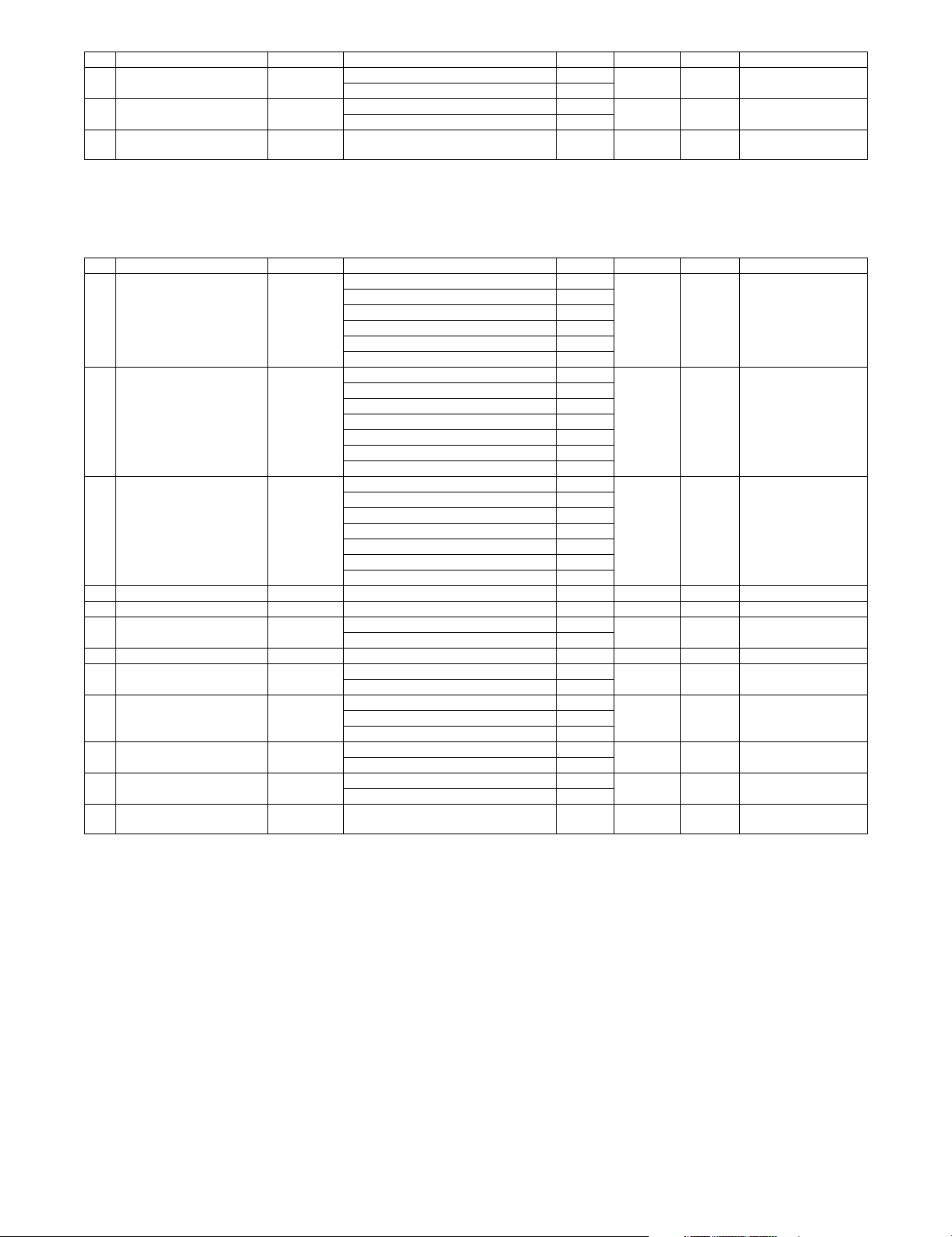
As the reference for the drum/developer life. the accumulated number of rotations can be displayed with SIM 22-1. The value displayed with SIM 22-1 indicates the reached level in percent (%)
when the developer/drum life is 100%.
Example) Life 550K, used number of rotations 385K
385/550 x 100 = 70 (%)
Number of rotations
of Developer/Drum
: Unit code/Model name
: Color code
: Destination
: Skating
: Production place
: Production date (YYYYMMDD)
: Serial number
: Version number
80,000
70,000
60,000
50,000
40,000
30,000
20,000
10,000
0
Numbers of printable quantity
Single multi
Single multi 33,000
2 sheets multi 52,000
3 sheets multi 64,000
4 sheets multi 72,000
2 sheets multi
3 sheets multi
4 sheets multi
MX-B382/B402 CONSUMABLE PARTS 2 – 3
Page 11
5. Life end display
A. Drum cartridge
Display content
Change the supplies. > Drum Cartridge 0 (Print continue) Drum cartridge print counter When 72K is reached Enable
The supplies will be needed soon.
> Drum Cartridge *1
Change the supplies. > Drum Cartridge 1 (Print stop) Drum cartridge print counter When 72K is reached Enable
Sim26-38-E
set value
Drum cartridge accumulated rotation number When 550K rotations is reached Enable
1 (Print stop) Drum cartridge print counter When 90% of 72K is reached by the
Drum cartridge accumulated rotation number When 90% of 550K rotation is
Drum cartridge accumulated rotation number When 550K rotations is reached Enable
Display condition
Counter name Counter value
counter
reached by the counter
When 72K + 1K is reached Disable
When 550K rotation + 430Kmm is
reached
Print job
Enable/
Disable
Enable
Enable
Disable
*1: Selection of Display/Not Display can be made with Sim26-69. (Default: Not Display)
• When the drum cartridge is replaced with a new one, the print counter, the accumulated traveling distance counter, the accumulated rotation
number counter, and the usage day counter are automatically cleared. If SIM26-55 setting is set to ENABLE in that case, the guidance for
execution of the automatic adjustment of the engine is displayed.
• If SIM26-55 setting is set to DISABLE, SIM46-74 must be used to execute the automatic adjustment of the engine.
• If the above guidance does not disappear when the drum cartridge is replaced, SIM24-7 must be executed to clear the print counter, the
accumulated traveling distance counter, the accumulated rotation number counter, and the usage day counter, and the engine automatic
adjustment must be executed.
• The above display disappears when the counters are cleared.
B. Developer section
Counter name End conditions
Developer print counter (K) 72,000 [sheets] Message (9) Message (9)
Developer accumulated rotation number (K) 550K rotations Message (9) Message (9)
Judgment is made at the earlier timing of the developer print counter or the developer accumulated rotation number counter.
The developer rotation number is synchronized with the drum motor rotation number.
Message when end over
Sim.26-38A “0”
Print Enable
Sim.26-38A “1”
Print Stop
Message
No.
(9) Maintenance required.Code: VK Enable
Message
Print job
Enable/Disable
After replacement of developer, use SIM25-2 to set the toner density control level. By this setting, the developer counters (the developer print
counter and the developer accumulated traveling distance counter) are cleared.
C. Toner cartridge
Display content
The supplies will be needed soon. > Toner Cartridge *2 25-0% Toner remaining quantity is 25% or less. Enable
Change the supplies. > Toner Cartridge 0% When the toner cartridge reaches toner end. Disable
No display 50-25% Toner remaining quantity is 49 - 25%. Enable
No display 75-50% Toner remaining quantity is 74 - 50%. Enable
No display 100-75% Toner remaining quantity is 100 -75%. Enable
Install the toner cartridge. No display When no toner cartridges are installed. Disable
Improper cartridge. No display When an incompatible toner cartridge is installed. Disable
Cartridge error. No display CRUM trouble
Remaining
quantity display *1
25-0% Toner remaining quantity corresponds to output of XX sheets. *3 Enable
Toner cartridge connector contact trouble
Display condition
Status
*1: Detected by the toner motor rotation number and the pixel count (The value of larger life percentage is employed.)
*2: Selection of Display/Not Display can be made with Sim26-69. (Default: Not Display)
*3: Setting can be made with Sim26-69. (Default: 0 sheet)
Print job
Enable/
Disable
Disable
MX-B382/B402 CONSUMABLE PARTS 2 – 4
Page 12
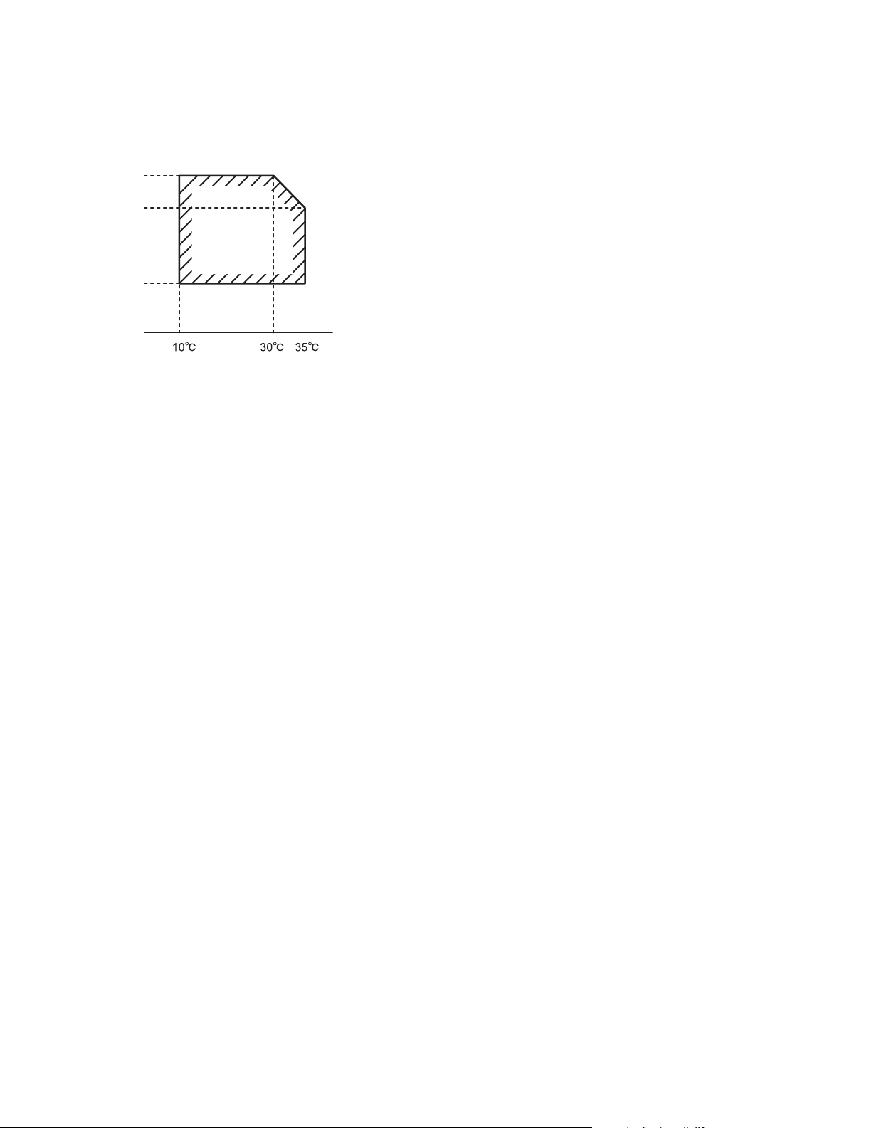
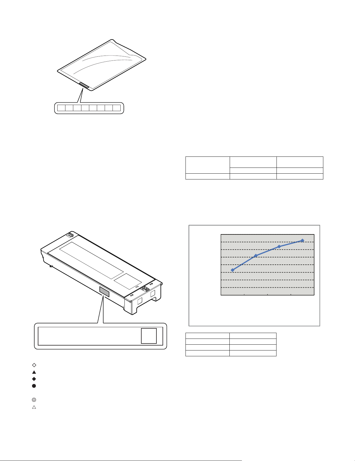
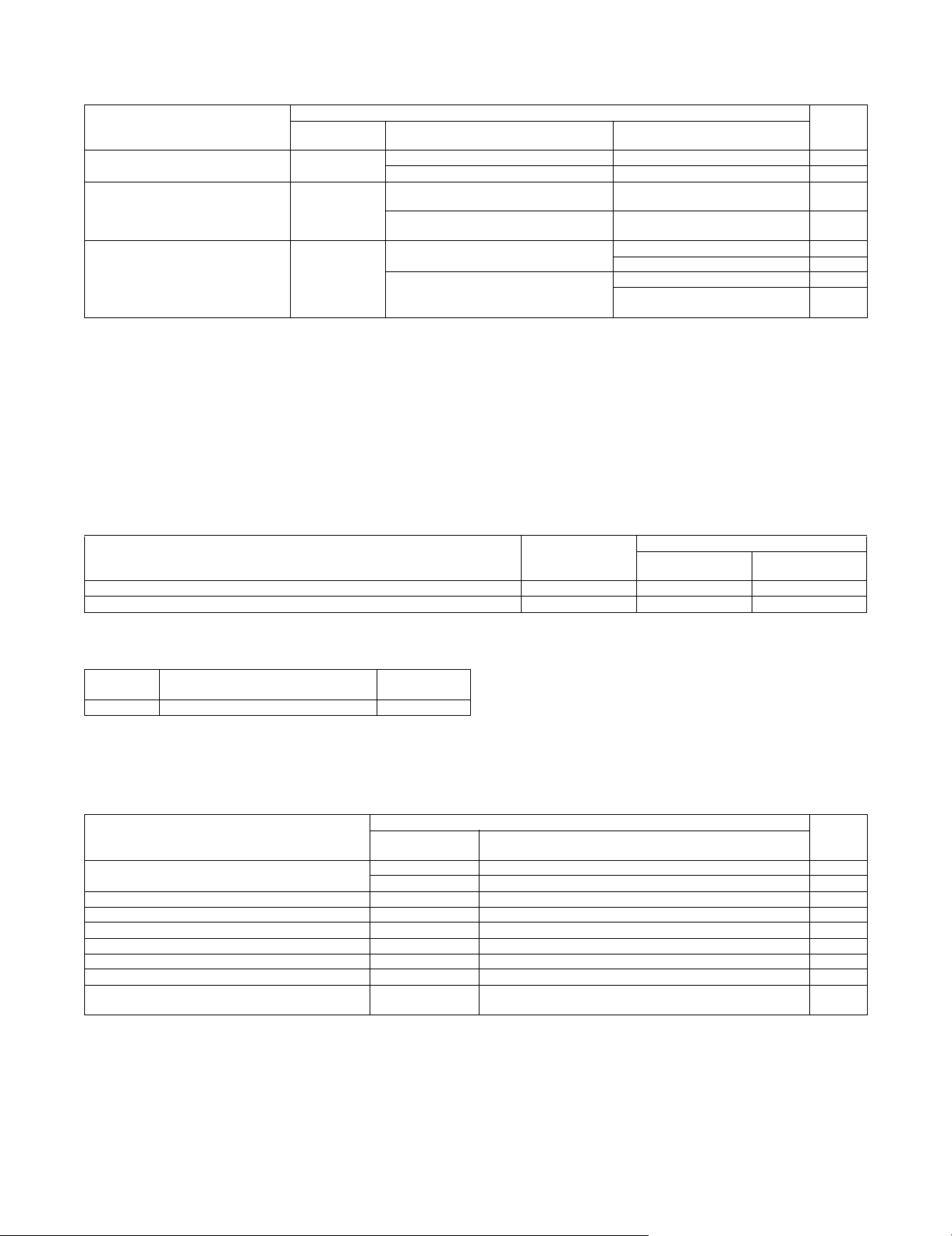
6. Environment conditions
A. Operating environment conditions
Temperature: 10 - 35C
Humidity: 20 - 85% RH
Atmospheric pressure: 590 - 1013hPa (Altitude: 0 - 2000m)
Humidity(RH)
85%
60%
20%
Temperature
B. Transit environment conditions
(term: 2 weeks)
-20 - 45C (Free from dew)
C. Storage environment conditions (unopened)
-10 - 40C (Free from dew)
D. Disposal standard
Toner cartridge/developer cartridge: 24 months (unopened) from
the production month.
Drum cartridge: 36 months from the production month
MX-B382/B402 CONSUMABLE PARTS 2 – 5
Page 13
2
3
5
1
12
11
14
13
6
7
8
9
4
10 11
MX-B402
[3] EXTERNAL VIEW AND INTERNAL STRUCTURE
Service Manual
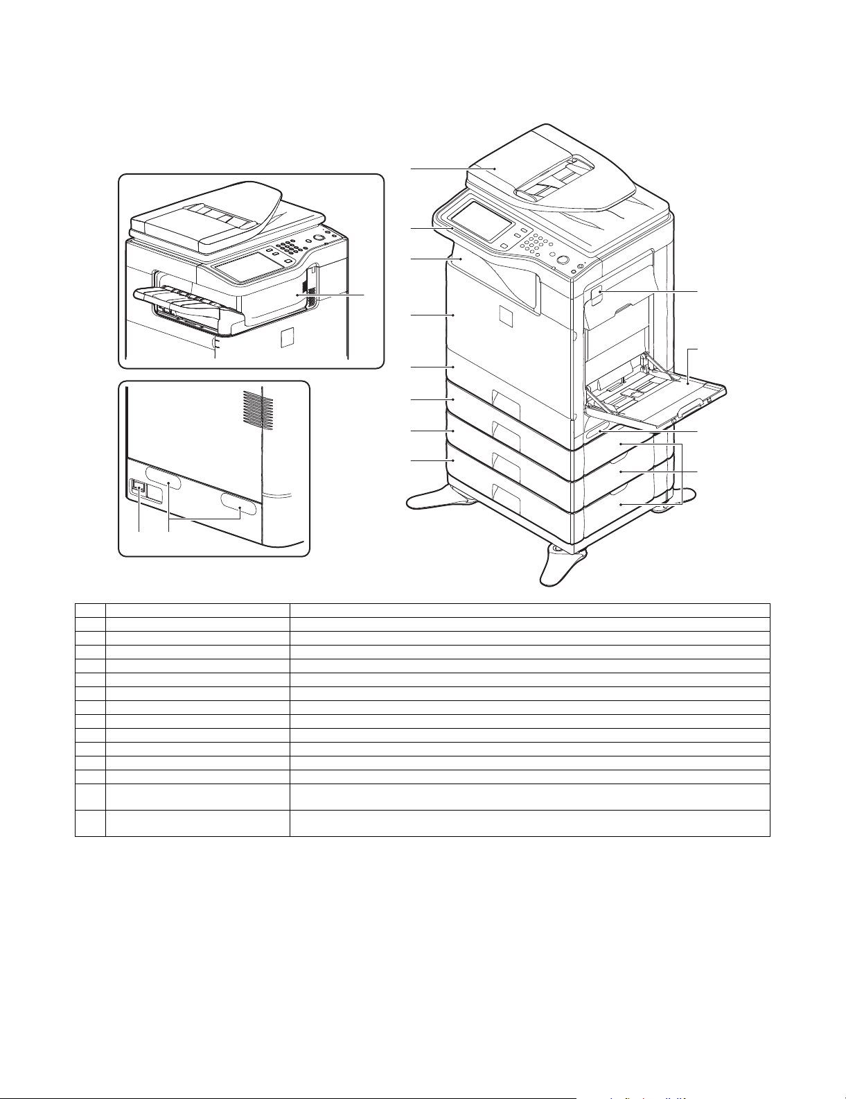
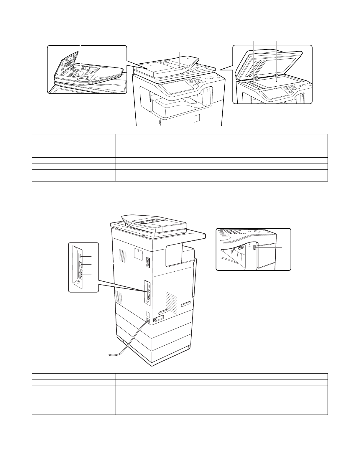
1. External view
No. Name Function/Operation
1 Auto document feeder Feeds the set documents automatically, and scans them continuously. The duplex surfaces are scanned.
2 Operation panel Used to enter an input of various settings or the copy quantity.
3 Paper exit tray (Center tray) Copied or printed paper is discharged to this tray.
4 Finisher *1 Delivers stapled paper, and allows offset discharge of paper.
5 Front cover This is opened when replacing toner cartridges or the waste toner box.
6 Tray 1 Stores paper. Max. 500 sheets (80g/m
7 Tray 2 (with the MX-CSX1 installed) *1 Stores paper. Max. 500 sheets (80g/m
8 Tray 3 (with the MX-CSX2 installed) *1 Stores paper. Max. 500 sheets (80g/m
9 Tray 4 (with the MX-CSX2 installed) *1 Stores paper. Max. 500 sheets (80g/m
10 Main power switch Turns on the power of the machine. When FAX or Internet FAX is used, keep it ON.
11 Handle Use this handle to lift the main unit for transit.
12 Right side cover release lever To remove paper jam, lift this lever and open the right side cover.
13 Manual paper feed tray For manual paper feed, paper is inserted from this tray. When A4R or 8-1/2" x 11"R paper is set, extend the
14 One-stage paper feed unit side cover
(with the MX-CSX1/2 installed)
*1: Option
2
, 21lbs)
2
, 21lbs)
2
, 21lbs)
2
, 21lbs)
auxiliary tray.
To remove paper jam in tray 2, 3, or 4, open this cover.
MX-B382/B402 EXTERNAL VIEW AND INTERNAL STRUCTURE 3 – 1
Page 14
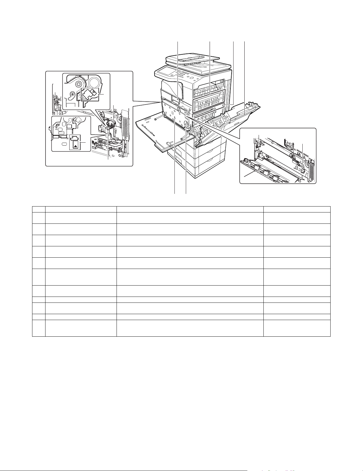
2. Internal structure
3
2
5
4
11
11
109
1 67
8
No. Name Function/Operation Note
1 Toner cartridge When toner is exhausted in a cartridge, remove the cartridge and replace it
2 Drum cartridge This cartridge stores a drum. When the specified life is reached, replace it
3 Developing unit This unit stores developer. When the specified life is reached, replace it with a
4 MC cleaning rod insertion port When the copy quality is degraded by dirt on the MC unit, the rod to clean the
5 LSU cleaning rod insertion port When the copy quality is degraded by dirt on the LSU, the rod to clean the
6 Fusing section Fuses images transferred on paper by heat. Note: The fusing section is heated
7 Transfer belt The transfer belt transfers toner on the drum. Do not touch or scratch. It may
8 Right side cover Opened when a paper jam is generated.
9 Waste toner box Receives waste toner when copying or printing. The waste toner box is collected
10 Waste toner box release lever When the waste toner box is removed, this lever is rotated to release lock.
11 Drum positioning plate unit release
lever
with a new one.
with a new cartridge.
new developer.
MC unit is inserted into this port.
LSU is inserted into this port.
Releases lock of the drum positioning plate unit. When a drum cartridge or a
developer cartridge is replaced, rotate this lever to open the drum positioning
plate unit.
to a high temperature. Be careful
not to burn when paper jam.
cause degraded images.
by the servicemen.
MX-B382/B402 EXTERNAL VIEW AND INTERNAL STRUCTURE 3 – 2
Page 15
3. RSPF
6
1 2 3 4 5 6 7
No. Name Function/ Operation
1 Document feed roller Transports a document automatically.
2 Document feed section cover This cover is opened when removing a paper jam or cleaning the document feed roller.
3 Document guide Guides to scan a document properly. Set to the set document size.
4 Document set table A document is set on this table. In the case of a single-surface document, set it face up.
5 Document exit section The scanned document is discharged to this section.
6 Document scan section The document set on the document set table is scanned in this section.
7 Document table (Glass surface) Used for thick documents or book documents which cannot be entered to the auto document feeder.
4. Connectors
1
5
2
3
4
No. Name Function/ Operation
1 USB connector (Type A) Used to connect a USB hub or USB memory.
2 LAN connector Used to connect a LAN cable to use this machine in a network.
3 USB connector (Type B) Used to connect a computer to use this machine as a printer.
4 Connector This connector is used by the serviceman.
5 Inner finisher connection connector This connector is used to connect the inner finisher and the main unit when the inner finisher (option) is installed.
6 USB connector (Type A) Used to connect a USB hub or USB memory.
MX-B382/B402 EXTERNAL VIEW AND INTERNAL STRUCTURE 3 – 3
Page 16
5. Operation panel
1 2 3 94 5 6
JOB STATUS
SYSTEM
SETTINGS
READY
PRINT
DAT A
IMAGE SEND
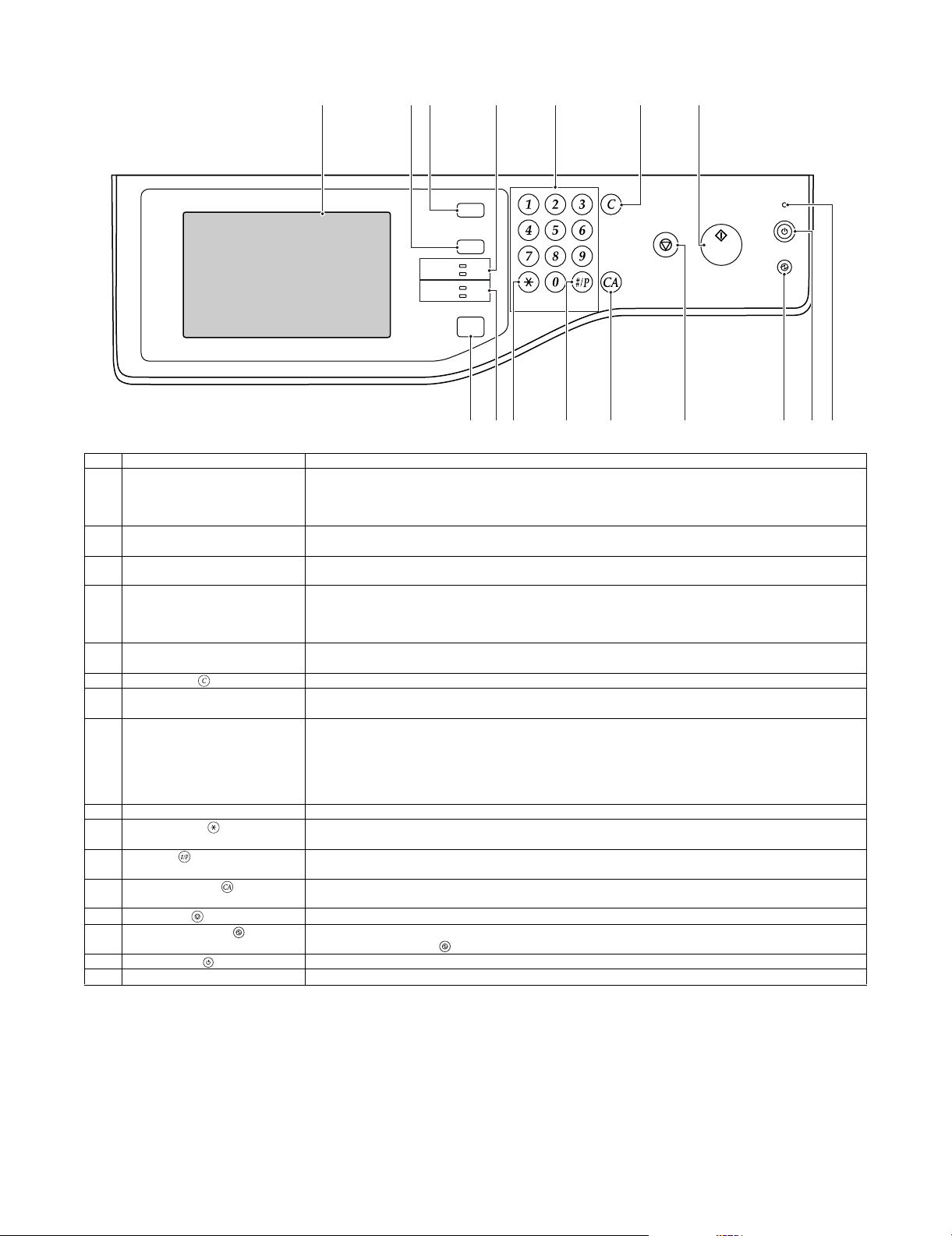
No. Name Function/Operation
1 Touch panel Messages and keys appear in the touch panel display.
Touch the displayed keys to perform a variety of operations.
When a key is touched, a beep sounds and the selected item is highlighted. This provides confirmation as you
perform an operation.
2 [SYSTEM SETTINGS] key Press this key to display the system settings menu screen. The system settings are used to configure paper tray
settings, store addresses for transmission operations, and adjust parameters to make the machine easier to use.
3 [JOB STATUS] key Press this key to display the job status screen. The job status screen is used to check information on jobs and to
cancel jobs.
4 PRINT mode indicators • READY indicator
Print jobs can be received when this indicator is lit.
• DATA indicator
This blinks while print data is being received and lights steadily while printing is taking place.
5 Numeric keys These are used to enter the number of copies, fax numbers, and other numerical values. These keys are also used
to enter numeric value settings (except for the system settings).
6 [CLEAR] key ( ) Press this key to return the number of copies to "0".
7 [HOME] key Touch this key to display the home screen. Frequently used settings can be registered in the home screen to
enable quick and easy operation of the machine.
8 IMAGE SEND mode indicators • LINE indicator
This lights up during transmission or reception of a fax or Internet fax. This also lights during transmission of an
image in scan mode.
• DATA indicator
This blinks when a received fax or Internet fax cannot be printed because of a problem such as out of paper.
This lights up when there is a transmission job that has not been sent.
9 [START] key Press this key to copy or scan an original. This key is also used to send a fax in fax mode.
10 [LOGOUT] key ( ) Press this key to log out after you have logged in and used the machine. When using the fax function, this key can
also be pressed to send tone signals on a pulse dial line.
11 [#/P] key ( ) When using the copy function, press this key to use a job program. When using the fax function, this key can be
used when dialing.
12 [CLEAR ALL] key ( ) Press this key to return to the initial operation state.
Use this key when you wish to cancel all settings that have been selected and start operation from the initial state.
13 [STOP] key ( ) Press this key to stop a copy job or scanning of an original.
14 [POWER SAVE] key ( ) / indicator Use this key to put the machine into auto power shut-off mode to save energy.
The [POWER SAVE] key ( ) blinks when the machine is in auto power shut-off mode.
15 [POWER] key ( ) Use this key to turn the machine power on and off.
16 Main power indicator This lights up when the machine's main power switch is in the "on" position.
LINE
DAT A
HOME
LOGOUT
LOGOUT
8 13 161510 117 12 14
MX-B382/B402 EXTERNAL VIEW AND INTERNAL STRUCTURE 3 – 4
Page 17
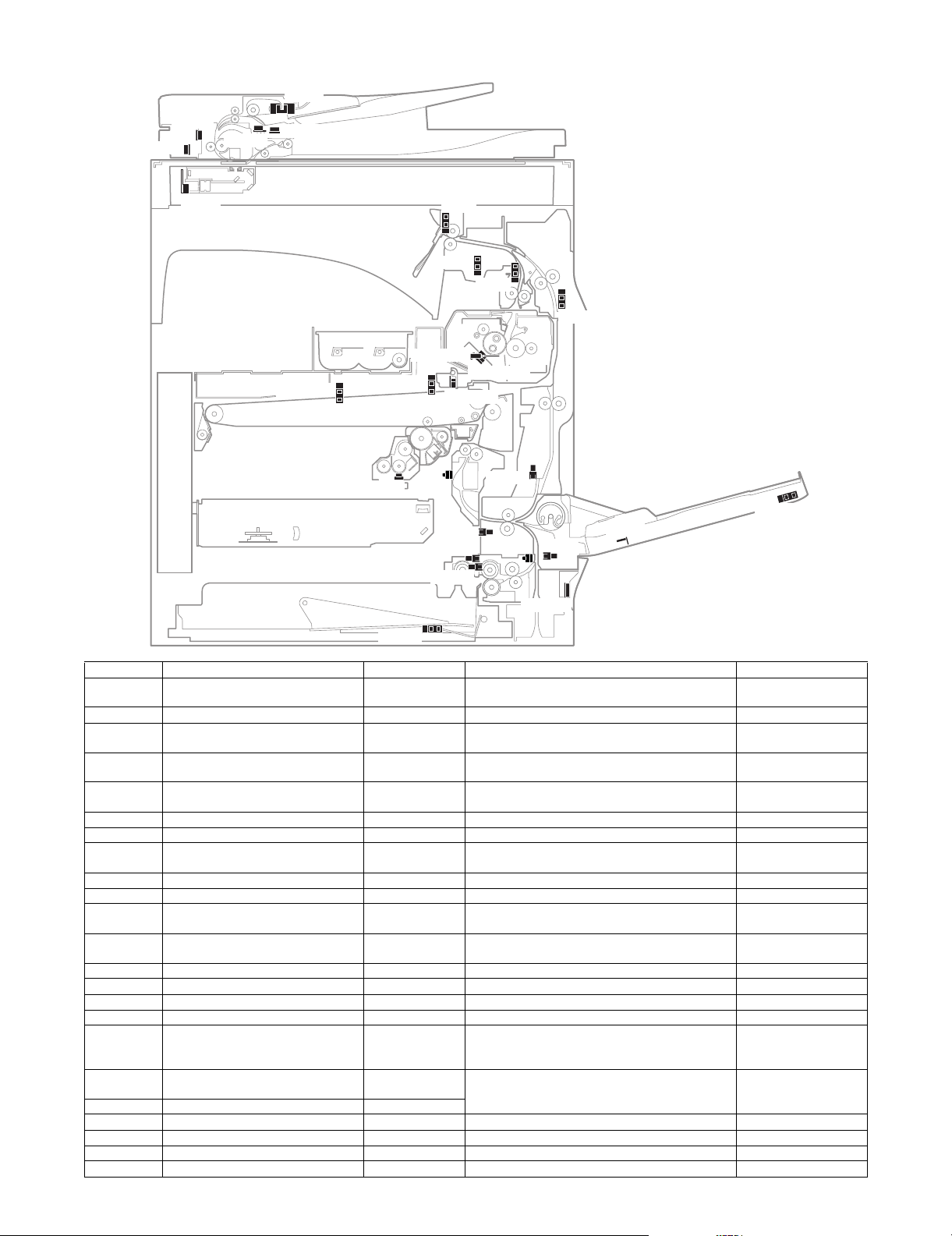
6. Sensors and detectors
SOCD
SCOV
SPED
MHPS
TFD2
TCS_K
PPD2
APPD2
CPED1
CSPD1
CLUD1
MPED
MPLD1
MPWS
TH/HUD
CPFD1
PPD1
POD2
POD1
APPD1
RTH_Sub
RTH_Main
1TUD_K
1TUD_CL
REGS_R
SPPD1
SPPD2
Signal name Name Type Function/Operation Note
1TUD_CL Transfer belt separation detector CL Transmission type Detects separation of the transfer belt. High voltage PWB
1TUD_K Transfer belt separation detector BK Transmission type Detects initialization of the primary transfer unit. Frame unit
APPD1 ADU transport path detector 1 Transmission type Detects paper pass in the upper stream of the
APPD2 ADU transport path detector 2 Transmission type Detects paper pass in the middle stream of the
CLUD1 Tray 1 upper limit detector Transmission type Detects that the top surface of the paper stored in the
CPED1 Tray 1 paper empty detector Transmission type Detects that paper is stored in the tray 1. Paper feed unit
CPFD1 Paper transport detector 1 Reflection type Detects paper when passes the transport roller 1. Paper feed unit
CSPD1 Tray 1 paper remaining quantity
MHPS Scanner home position detector Transmission type Detects the scanner home position. Scanner unit
MPED Manual feed paper empty detector Transmission type Detects paper empty in the manual paper feed tray. Manual paper feed unit
MPLD1 Manual feed paper length detector 1 Transmission type Detects the length of paper in the manual paper feed
MPWS Manual paper feed tray paper width
POD1 Fusing rear detector Transmission type Detects paper exit from the fusing section. Frame fusing unit
POD2 Paper exit detector Transmission type Detects paper which is discharged. Paper exit lower PG unit
PPD1 Paper transport detector 2 Transmission type Detects paper when passes the transport roller 2. Paper feed unit
PPD2 Paper transport detector 3 Reflection type Detects paper in front of the registration roller. Frame unit
REGS_R Registration sensor Reflection type Detects the toner patch density. Detects open/close of
RTH_Main Upper heat roller non-contact
RTH_Sub Upper heat roller contact thermistor Thermistor
SCOV RSPF cover open/close detector Transmission type Detects open/close of the RSPF cover. RSPF unit
SOCD RSPF open/close detector Transmission type Detects open/close of the RSPF unit itself. RSPF unit
SPED RSPF document empty detector Transmission type Detects that a document is in the document tray. RSPF unit
SPPD1 RSPF transport detector 1 Transmission type Detects a document which passes the paper path. RSPF unit
detector
sensor
thermistor
switchback section.
switchback section.
Transmission type Detects the paper remaining quantity in the tray 1. Lift-up unit
tray 1 is lifted to the top.
tray.
paper feed tray.
Volume resistor Detects the width of the paper guide in the manual
the reference reflection plate, the secondary transfer
Non-contact
thermistor
roller transfer position, and the non-transfer position.
Detects the temperature of the upper heat roller. Fusing unit
MX-B382/B402 EXTERNAL VIEW AND INTERNAL STRUCTURE 3 – 5
holder unit
Right door unit
Right door unit
Paper feed unit
Manual paper feed unit
Manual paper feed unit
Registration unit
Page 18
Signal name Name Type Function/Operation Note
SPPD2 RSPF transport detector 2 Transmission type Detects a document which passes the paper path. RSPF unit
TCS_K Toner density sensor Magnetic sensor Detects the toner density in the developing cartridge. Developing cartridge
TFD2 Paper exit tray full detector Transmission type Detects the full state of the paper exit tray. Paper exit upper PG unit
TH/HUD Temperature humidity sensor Temperature
humidity sensor
Detects the temperature and the humidity around the
machine.
Right door unit
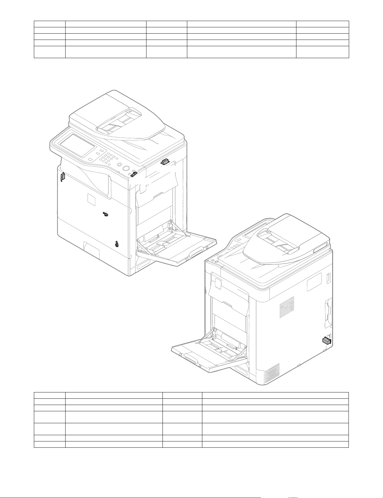
7. Switches
DSW-R
DSW-F
PWRSW
DRCRU_K
1TNFD
MSW
Signal name Name Type Function/Operation
1TNFD Waste toner full detection switch Micro switch Detects the waste toner full.
DRCRU_K OPC drum initial (new OPC drum) detector (BK) Micro switch Detects the OPC drum initial state (new OPC drum).
DSW-F Front door open/close switch Micro switch Detects open/close of the front door, and turns ON/OFF the power line of
DSW-R Right door open/close switch Micro switch Detects open/close of the right door unit, and turns ON/OFF the power
MSW Main switch Seesaw switch Turns ON/OFF the main DC power source.
PWRSW Operation panel power switch Push switch Outputs the ON/OFF control signal of the DC power source.
the fusing, the motor and the LSU laser.
line of the fusing, the motor and the LSU laser.
MX-B382/B402 EXTERNAL VIEW AND INTERNAL STRUCTURE 3 – 6
Page 19
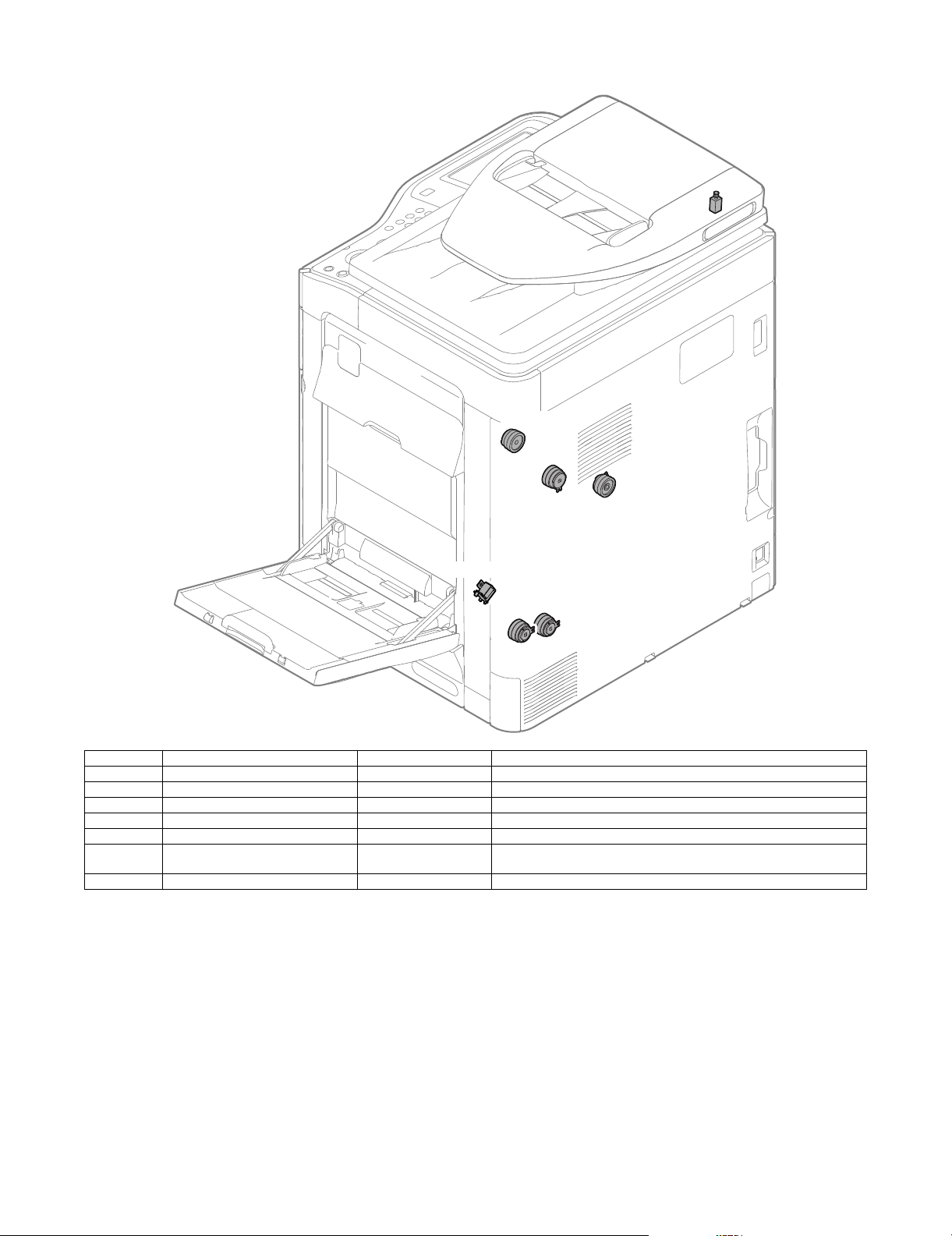
8. Clutches and solenoids
SPUS
ADUC1
2TURC
1TURC_1
MPFS
CPUC1
CPFC
Signal name Name Type Function/Operation
1TURC_1 Primary transfer separation clutch 1 Electromagnetic clutch Controls the primary transfer separation mode.
2TURC Secondary transfer separation clutch Electromagnetic clutch Controls open/close of the resist sensor cover.
ADUC1 ADU transport clutch 1 Electromagnetic clutch Controls ON/OFF of the roller in the switchback section.
CPFC Tray vertical transport clutch Electromagnetic clutch Controls ON/OFF of the paper transport roller in the tray paper feed section.
CPUC1 Paper feed clutch (Tray paper feed) Electromagnetic clutch Controls ON/OFF of the roller in the tray paper feed section.
MPFS Paper pickup solenoid
(Manual paper feed)
SPUS RSPF paper feed roller solenoid Electromagnetic solenoid Controls ON/OFF of the paper feed roller in the RSPF paper feed section.
Electromagnetic solenoid Controls ON/OFF of the pick-up operation of the paper feed roller in the
manual paper feed section.
MX-B382/B402 EXTERNAL VIEW AND INTERNAL STRUCTURE 3 – 7
Page 20
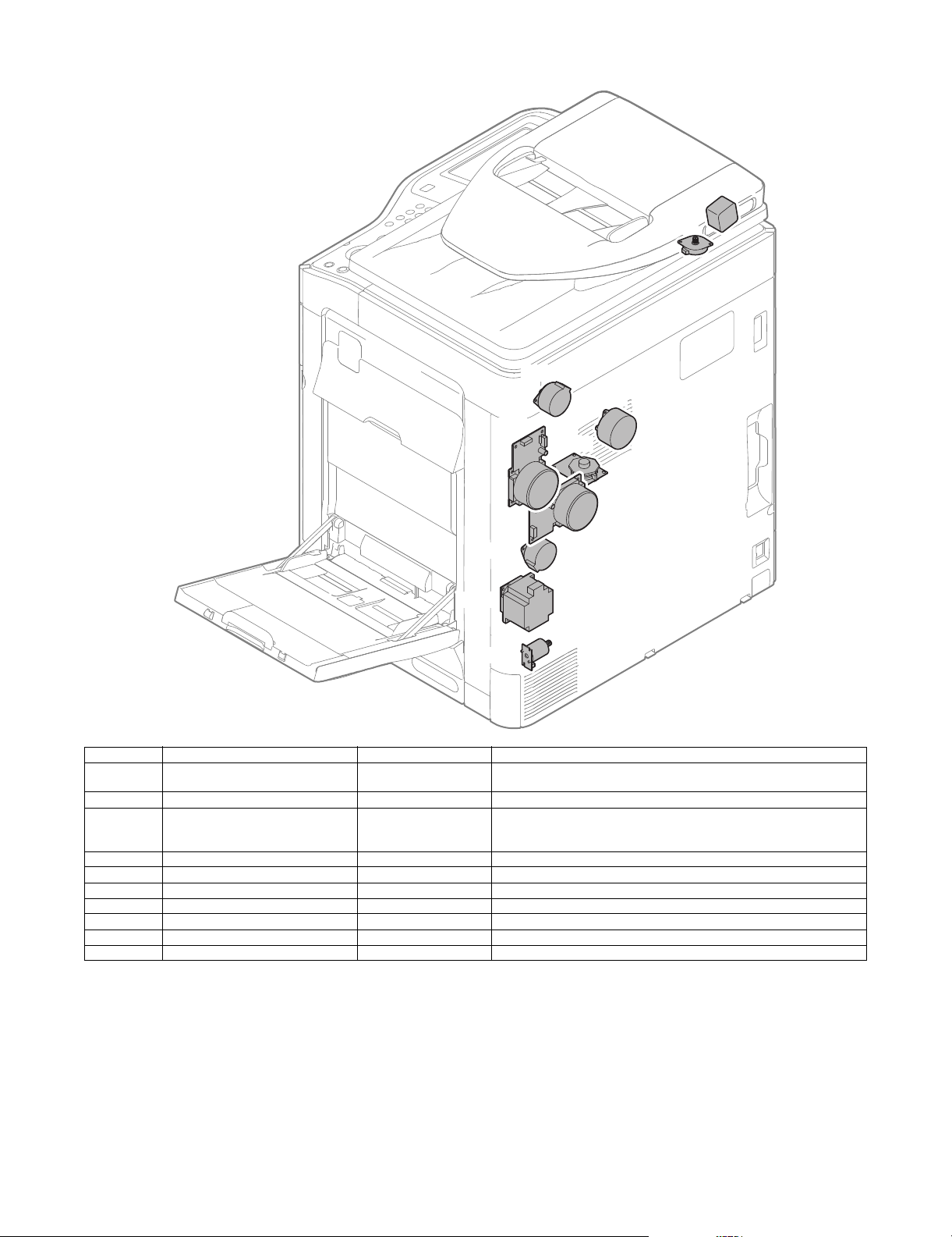
9. Drive motors
SPFM
MIM
POM
TNM_K
FUM
PGM1
RRM
DVM_K
CPFM
CLUM
Signal name Name Type Function/Operation
CLUM Paper tray lift-up motor
(Paper feed tray 1)
CPFM Paper feed motor Stepping motor Drives the paper feed section.
DVM_K Developing drive motor Brush-less motor Drives the development cartridge, the drum cartridge, the primary transfer
FUM Fusing drive motor DC brush motor Drives the fusing unit.
MIM Scanner motor Stepping motor Drives the carriage unit.
PGM1 Polygon motor 1 DC brush-less motor Scans the laser beam.
POM Paper exit drive motor Stepping motor Drives the paper exit roller.
RRM Registration motor Stepping motor Drives the resist roller and controls ON/OFF.
SPFM RSPF transport motor Stepping motor Drives the RSPF unit.
TNM_K Toner motor K Synchronous motor Transports toner from the toner cartridge to the developing unit.
DC brush-less motor Drives the lift plate of the paper feed tray.
unit, and the secondary transfer unit.
Also separates the primary transfer unit.
MX-B382/B402 EXTERNAL VIEW AND INTERNAL STRUCTURE 3 – 8
Page 21
10. Lamps
CLI
CCFT
HL_UM
DL_K
HL_UA
Signal name Name Type Function/Operation
CCFT LCD back-light CCFT cool cathode ray tube Back-light for the LCD
CLI Scanner lamp CCFL (Cold cathode fluorescent lamp) Radiates lights onto a document for the CCD to scan document images.
DL_K Discharge lamp K LED Discharges electric charges on the OPC drum.
HL_UM Upper heater lamp Halogen lamp Heats the upper heat roller. (main)
HL_UA Upper heater lamp Halogen lamp Heats the upper heat roller. (all)
MX-B382/B402 EXTERNAL VIEW AND INTERNAL STRUCTURE 3 – 9
Page 22
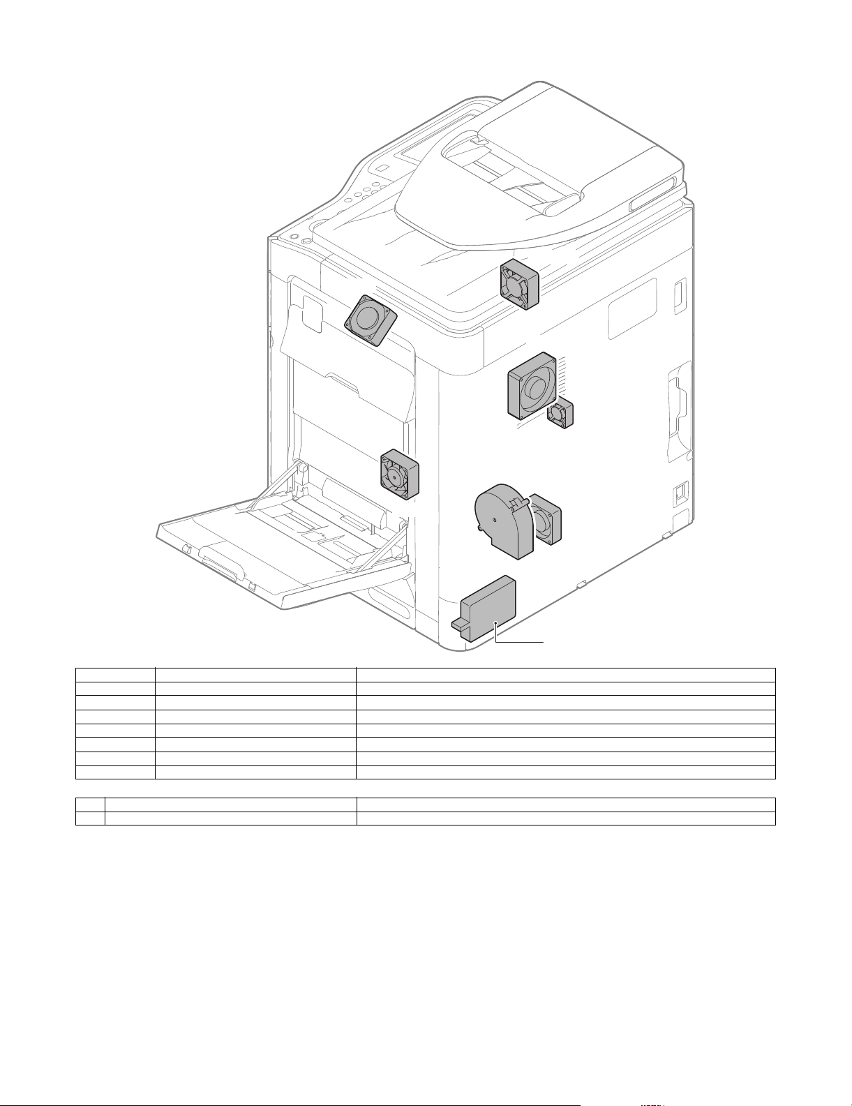
11. Fans and filter
PROFM1
POFM
FUFM
HDDFAN
PROFM2
LSUFM
PSFM
1
Signal name Name Function/Operation
FUFM Fusing cooling fan motor Cools the fusing unit.
HDDFM HDD cooling fan motor Cools the HDD.
LSUFM LSU cooling fan motor Cools the LSU.
POFM Paper exit cooling fan motor Cools the paper exit section.
PROFM1 Process fan motor 1 Cools the process section.
PROFM2 Process fan motor 2 Exhausts ozone.
PSFM Power PWB cooling fan motor Cools the power PWB.
No. Name Function/Operation
1 Ozone filter Absorbs ozone generated in the image process section.
MX-B382/B402 EXTERNAL VIEW AND INTERNAL STRUCTURE 3 – 10
Page 23
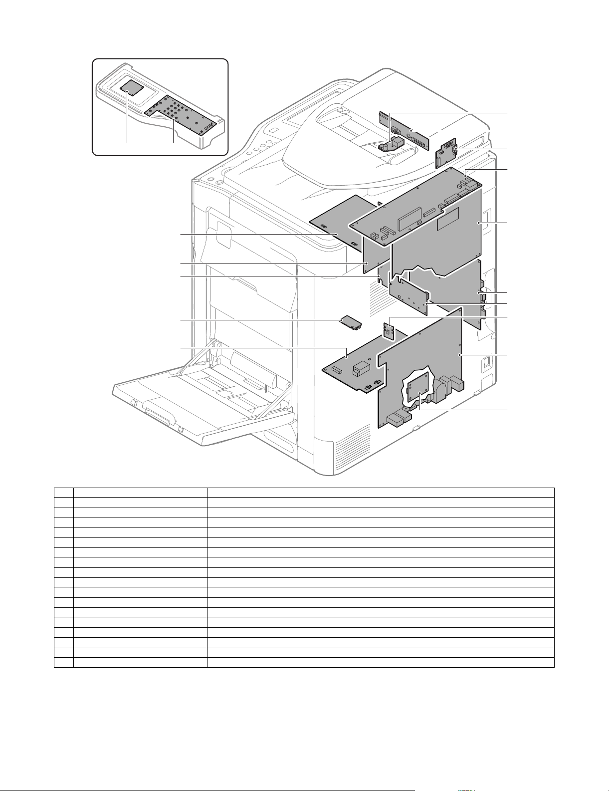
12. PWB
12
8
9
11
10
7
5
3
6
1 2
4
16
17
15
13
14
No. Name Function/Operation
1 LVDS PWB Converts the display signal and outputs to the LCD.
2 MFP OPE-P PWB Outputs the key operation signal.
3 CL inverter PWB Drives the scanner lamp.
4 CCD PWB Scans the document images.
5 RSPF driver PWB Controls the RSPF.
6 Scanner control PWB Controls the scanner section.
7 PCU PWB Controls the engine section.
8 MFPC PWB Controls images and the whole machine.
9 LD PWB Controls laser lighting.
10 BD PWB Detects laser and outputs the synchronous signal.
11 ACDC power PWB Controls the primary side power source and outputs the secondary side voltage.
12 Paper size detection PWB Detects the paper size in the tray 1.
13 MC PWB Generates the high voltage for the main charger and the developing bias voltage.
14 DV initial PWB Detects the DV model.
15 LSU MOTHER PWB Controls the LSU. Interfaces the MFPC PWB and PCU PWB.
16 HL PWB Controls the heater lamp.
17 TC PWB Generates each transfer voltage and separation voltage.
MX-B382/B402 EXTERNAL VIEW AND INTERNAL STRUCTURE 3 – 11
Page 24
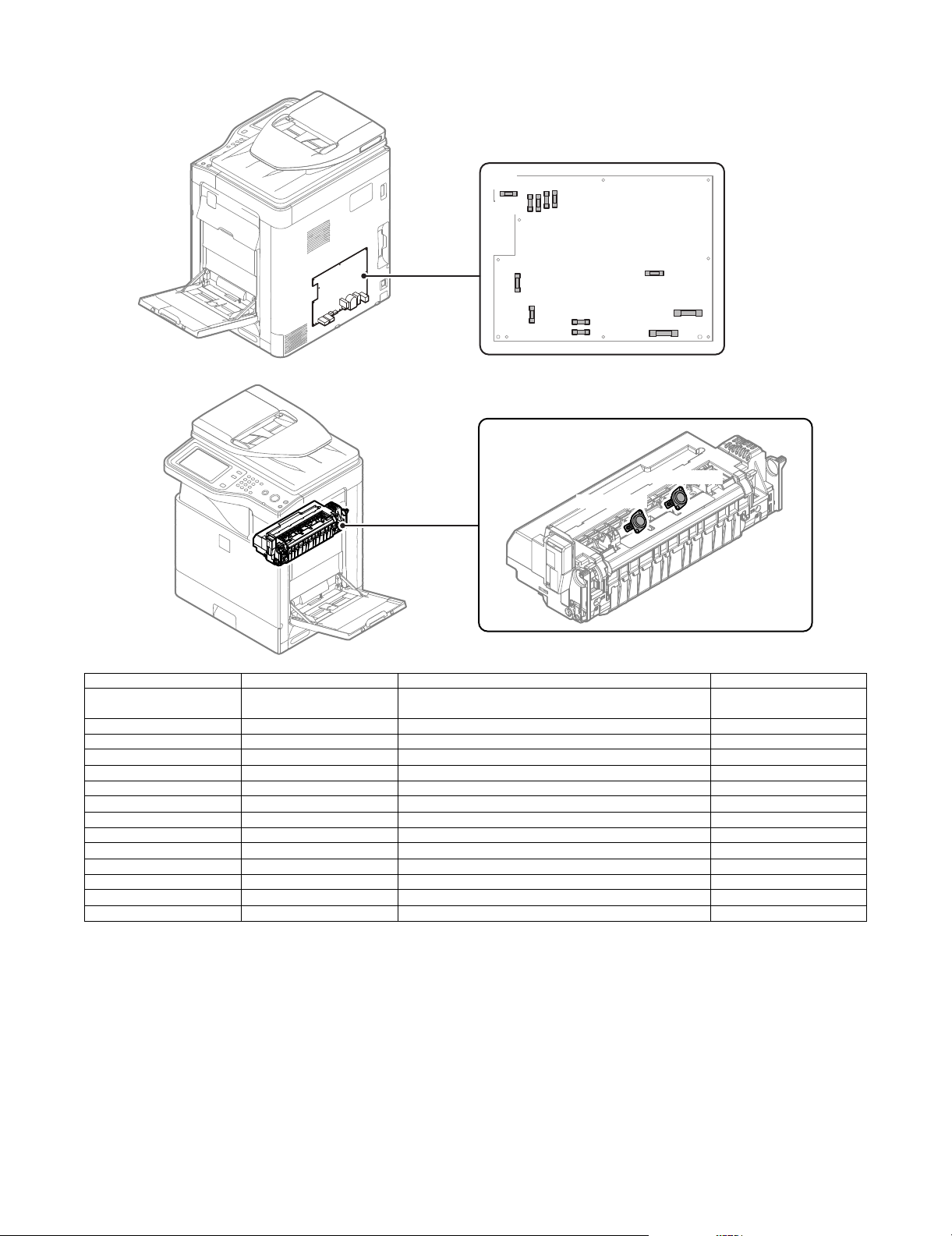
13. Fuses and Thermostats
F401
F402
F403
F405
F404
F301
F002
F001
F003
F004
F101
F201
RDTCT_UM
RDTCT_UA
Signal name Name Specifications Section
F001 Fuse AC250V T10AH (200V series)
F002 Fuse AC250V T10AH (200V series) (Not provided in 120V series) ACDC power PWB
F003 Fuse AC250V T2AH (Common in 200V series and 120V series) ACDC power PWB
F004 Fuse AC250V T2AH (200V series) (Not provided in 120V series) ACDC power PWB
F101 Fuse AC250V T2AH (Common in 200V series and 120V series) ACDC power PWB
F201 Fuse AC250V T5AH (Common in 200V series and 120V series) ACDC power PWB
F301 Fuse AC250V T2AH (Common in 200V series and 120V series) ACDC power PWB
F401 Fuse AC250V T4AH (Common in 200V series and 120V series) ACDC power PWB
F402 Fuse AC250V T6.3AH (Common in 200V series and 120V series) ACDC power PWB
F403 Fuse AC250V T6.3AH (Common in 200V series and 120V series) ACDC power PWB
F404 Fuse AC250V T6.3AH (Common in 200V series and 120V series) ACDC power PWB
F405 Fuse AC250V T6.3AH (Common in 200V series and 120V series) ACDC power PWB
RDTCT_UA Upper thermostat (all) Prevents against overheating of the fusing roller. Fusing unit
RDTCT_UM Upper thermostat (main) Prevents against overheating of the fusing roller. Fusing unit
AC250V 20A (120V series)
ACDC power PWB
MX-B382/B402 EXTERNAL VIEW AND INTERNAL STRUCTURE 3 – 12
Page 25
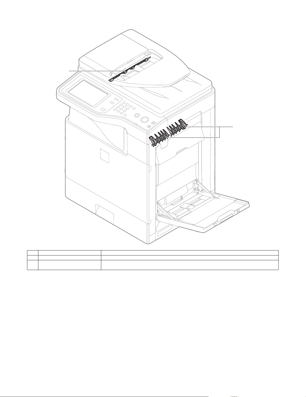
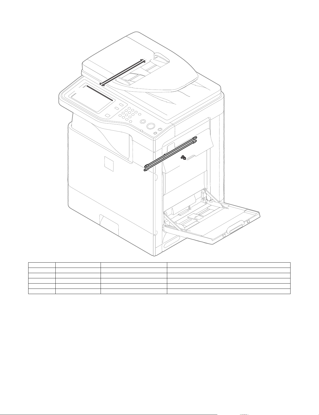
14. Gates
1
2
No. Name Function/ Operation
1 Switchback gate Guides paper which is switched back by the paper exit roller to the switchback section in the duplex copy mode.
2 RSPF reverse gate Guides paper which is switched back by the paper exit roller to the transport roller 4 when duplex scanning of a
MX-B382/B402 EXTERNAL VIEW AND INTERNAL STRUCTURE 3 – 13
document is performed.
Page 26
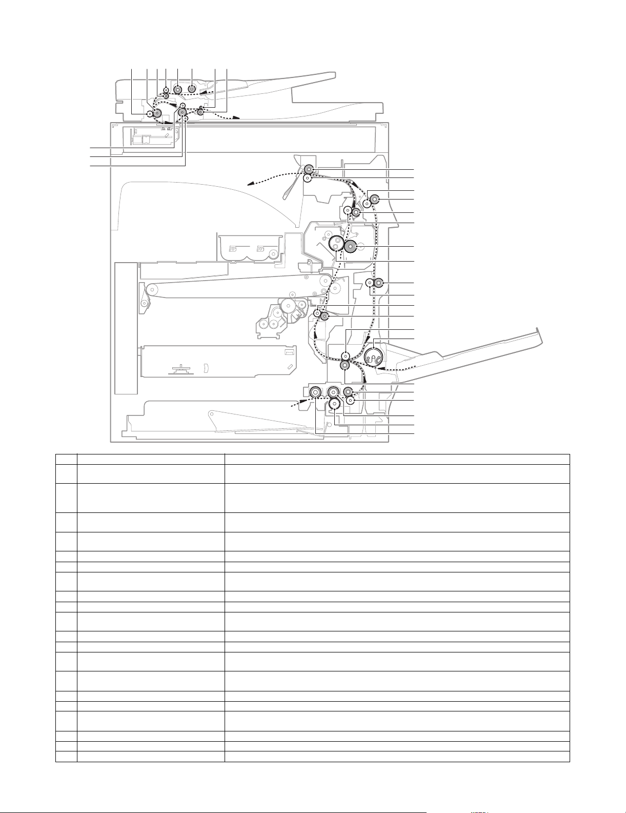
15. Rollers
3
2
1
8754 6 10 119
12
13
14
15
16
17
18
19
20
21
22
23
24
25
26
27
28
29
30
31
No. Name Function/ Operation
1 Transport roller 3 (Idle) (RSPF) Applies a pressure to the document and the transport roller to give a transport power of the transport roller
2 Transport roller 3 (Drive) (RSPF) Transports the document from the transport roller 2 to the paper exit roller.
3 Transport roller 4 (Idle) (RSPF) Applies a pressure to the document and the transport roller to give a transport power of the transport roller
4 Transport roller 2 (Idle) (RSPF) Applies a pressure to the document and the transport roller to give a transport power of the transport roller
5 Transport roller 2 (Drive) (RSPF) Transports the document from the transport roller 1 to the transport roller 3.
6 Transport roller 1 (Drive) (RSPF) Transports the document fed from the document tray to the transport roller 2.
7 Transport roller 1 (Idle) (RSPF) Applies a pressure to the document and the transport roller to give a transport power of the transport roller
8 Paper feed roller (RSPF) Feeds the document to the transport section.
9 Paper pickup roller (RSPF) Transports the document to the separation roller.
10 Paper exit roller (Idle) (RSPF) Applies a pressure to the document and the transport roller to give a transport power of the transport roller
11 Paper exit roller (Drive) (RSPF) Discharges the document. Transports the document to the transport roller 2 in the duplex scanning mode.
12 Paper exit roller (Drive) Discharges the paper. / Transports the paper to the switchback section.
13 Paper exit roller (Idle) Applies a pressure to the paper and the paper exit roller to give a transport power of the paper exit roller to
14 Transport roller 4 (Idle) Applies a pressure to the paper and the transport roller to give a transport power of the transport roller to
15 Transport roller 4 (Drive) Transports the paper switched back by the paper exit roller to the transport roller 5.
16 Transport roller 3 (Drive) Transports the paper from the fusing roller to the paper exit roller.
17 Transport roller 3 (Idle) Applies a pressure to the paper and the transport roller to give a transport power of the transport roller to
18 Fusing roller (Heating) Heats and presses toner on the paper to fuse on the paper.
19 Fusing roller (Pressing) Applies a pressure to the fusing roller (heating).
20 Transport roller 5 (Drive) Transports the paper from the transport roller 4 to the transport roller 2.
to the document.
Transports the document switched back by the paper exit roller to the transport roller 2 in the duplex
scanning mode.
to the document.
to the document.
to the document.
to the document.
the paper.
the paper.
the paper.
MX-B382/B402 EXTERNAL VIEW AND INTERNAL STRUCTURE 3 – 14
Page 27

No. Name Function/ Operation
21 Transport roller 5 (Idle) Applies a pressure to the paper and the transport roller to give a transport power of the transport roller to
22 Resist roller (Idle) Applies a pressure to the paper and the resist roller, giving a transport power of the resist roller to the
23 Resist roller (Drive) Transports paper to the transfer section. / Controls the paper transport timing, and adjusts the relative
24 Transport roller 2 (Idle) Applies a pressure to the paper and the transport roller to give a transport power of the transport roller to
25 Paper feed roller (Manual paper feed tray) Transports paper to the transport roller 2.
26 Transport roller 2 (Drive) Transports the paper transported from the transport roller 1 to the resist roller.
27 Transport roller 1 (Drive) Transports paper which was fed from the paper feed tray 1 to the transport roller 2.
28 Transport roller 1 (Idle) Applies a pressure to the paper and the transport roller to give a transport power of the transport roller to
29 Paper feed roller (No. 1 paper feed tray) Transport paper to the paper transport section.
30 Separation roller (No. 1 paper feed tray) Separates paper to prevent against double feed.
31 Paper pickup roller (No. 1 paper feed tray) Transports paper to the paper feed roller.
the paper.
paper.
relations between images and paper.
the paper.
the paper.
MX-B382/B402 EXTERNAL VIEW AND INTERNAL STRUCTURE 3 – 15
Page 28
MX-B402
[4] ADJUSTMENTS
Service Manual
1. General
Each adjustment item in the adjustment item list is associated with
a specific Job number. Perform the adjustment procedures in the
sequence of Job numbers from the smallest to the greatest.
However, there is no need to perform all the adjustment items. Perform only the necessary adjustments according to the need.
Unnecessary adjustments can be omitted. Even in this case, however, the sequence from the smallest to the greatest Job number
must be observed.
If the above precaution should be neglected, the adjustment would
not complete normally or trouble may occur.
2. Adjustment item list
Job No Adjustment item list Simulation
ADJ 1 Adjusting high voltage values 1A Adjust the main charger grid voltage 8-2
ADJ 2 Image density sensor adjustment 44-2
ADJ 3 Image skew adjustment (LSU unit) 64-2
ADJ 4 Print engine image magnification ratio adjustment (Main scanning direction) (Print engine section) (Manual adjustment) 50-10
ADJ 5 Image off-center adjustment (Print engine section) 50-10
ADJ 6 Scan image magnification ratio
adjustment (Document table
mode)
ADJ 7 Scan image magnification ratio
adjustment (Main/sub scanning
direction) (RSPF mode)
ADJ 8 Scan image off-center
adjustment
ADJ 9 Print area (Void area) adjustment (Print engine section) 50-10/50-1
ADJ 10 Copy image position, image loss
adjustment
ADJ 11 Print lead edge image position adjustment (Printer mode) (Print engine section) 50-5
ADJ 12 Copy density and gradation
adjustment
ADJ 13 Printer density and gradation
adjustment
ADJ 14 Manual paper feed tray paper size (width) sensor adjustment 40-2
ADJ 15 Touch panel coordinate setting 65-1
ADJ 16 Image loss, void area, image off-
center, image magnification ratio
auto adjustment with SIM50-28
ADJ 17 Fusing paper guide position adjustment
1B Adjust the developing bias voltage 8-1
1C Transfer voltage adjustment 8-6
6A Scan image magnification ratio adjustment (Main scanning direction) (Document table mode) 48-1
6B Scan image magnification ratio adjustment (Sub scanning direction) (Document table mode) 48-1
7A Scan image magnification ratio adjustment (Main scanning direction) (RSPF mode) 48-1
7B Scan image magnification ratio adjustment (Sub scanning direction) (RSPF mode) 48-1
8A Scan image off-center adjustment (Document table mode) 50-12
8B Scan image off-center adjustment (RSPF mode) 50-12
10A Copy image position, image loss adjustment (Document table mode) 50-1 (50-2)
10B Adjust the original scan start position (Adjust the scanner read position in RSPF mode front
face scan)
10C Copy image position, image loss adjustment (RSPF mode) 50-6 (50-7)
12A CCD gamma adjustment (CCD calibration) 63-3 (63-5)
12B Copy density and gradation adjustment (Auto adjustment) 46-24
12C Copy density and gradation adjustment (Manual adjustment) 46-21
12D Copy density and gradation adjustment (Each copy mode) (Whole adjustment)
(Normally unnecessary to adjust)
12E Condition setting of document density reading operation (exposure) in the auto copy mode
(Normally not required)
12F Document background density reproducibility adjustment in the auto copy mode (Normally
unnecessary to adjust)
12G Color document reproducibility adjustment in the copy mode
(Normally unnecessary to adjust)
12H Sharpness adjustment in the auto copy mode (Normally unnecessary to adjust) 46-60
12I Copy high density part density correction setting (Prevents against tone gap)
(Normally unnecessary to adjust)
12J Copy density and gradation adjustment in the RSPF mode (Normally unnecessary to adjust) 46-9
12K Auto copy density and gradation adjustment by the user
(Copy auto adjustment enable setting and adjustment)
13A Printer density and gradation adjustment (Auto adjustment) 67-24
13B Printer density and gradation adjustment (Manual adjustment) 67-25
13C Printer density and gradation adjustment (low density part density and gradation adjustment)
(Normally unnecessary to adjust)
13D Printer high density part density correction setting
(High density part tone gap countermeasure) (Normally unnecessary to the setting change)
13E Auto density and gradation adjustment by the user (Printer auto adjustment ENABLE setting
and adjustment)
13F Copy/Printer density and gradation adjustment (Automatic adjustment) 46-74
16A Print image main scanning direction image magnification ratio automatic adjustment 50-28
16B Image off-center automatic adjustment (Document table mode) 50-28
16C Copy lead edge image reference position adjustment, image off-center, sub scanning
direction image magnification ratio automatic adjustment (Document table mode)
16D SPF mode image off-center, image lead edge position, sub scanning direction image
magnification ratio automatic adjustment (RSPF mode)
53-8
46-2
46-19
46-32
46-37
46-23
46-53
67-36
67-34
26-54
50-28
50-28
MX-B382/B402 ADJUSTMENTS 4 – 1
Page 29
Job No Adjustment item list Simulation
ǂǂǂ6,08/$7,21ǂǂ12
&/26(
7(67
0+9*5,'6(77,1*$1'287387
$˖
˷˹
˖0,''/(63(('*%B.
$˖
2.
(;(&87(
/2:
0,''/(
ǂǂǂ6,08/$7,21ǂǂ12
&/26(
7(67
'96(77,1*$1'287387
$˖
˷˹
˖0,''/(ǂ63(('ǂ'9%B.
$˖
2.
(;(&87(
/2:
0,''/(
ADJ 18 Adjust the developing unit 18A Adjust the developing doctor gap
18B Adjust the developing roller main pole position
18C Toner density control reference value setting 25-2
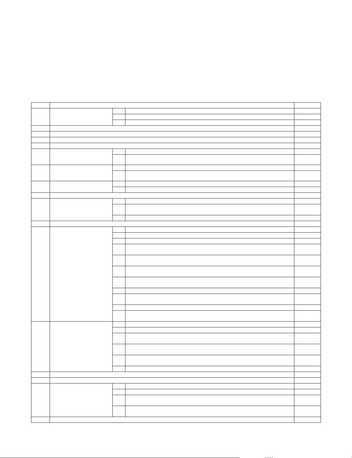
3. Details of adjustment
ADJ 1 Adjusting high voltage values
1-A Adjust the main charger grid voltage
This adjustment is needed in the following situations:
* When the MC high voltage power PWB is replaced.
* U2 trouble has occurred.
* The PCU PWB has been replaced.
* The EEPROM of the PCU PWB has been replaced.
1) Enter the SIM 8-2 mode.
2) Select an output mode and an item to be adjusted.
3) Enter the adjustment value (specified value) in the middle
speed mode, and press [OK] key.
When [EXECUTE] key is pressed, the voltage entered in the
procedure 3 is outputted for 30sec and the set value is saved.
When [EXECUTE] key is pressed, the output is stopped.
Enter the adjustment value of each mode which is specified on the label attached on the MC high voltage power
PWB.
When the adjustment value (specified value) of the middle speed
mode is set, the adjustment values of the other modes are automatically set according to the middle speed mode setting in a certain relationship.
NOTE: Since the high voltage output cannot be checked with a
digital multi meter in this model, a judgment of the output
must be made by checking the print image quality.
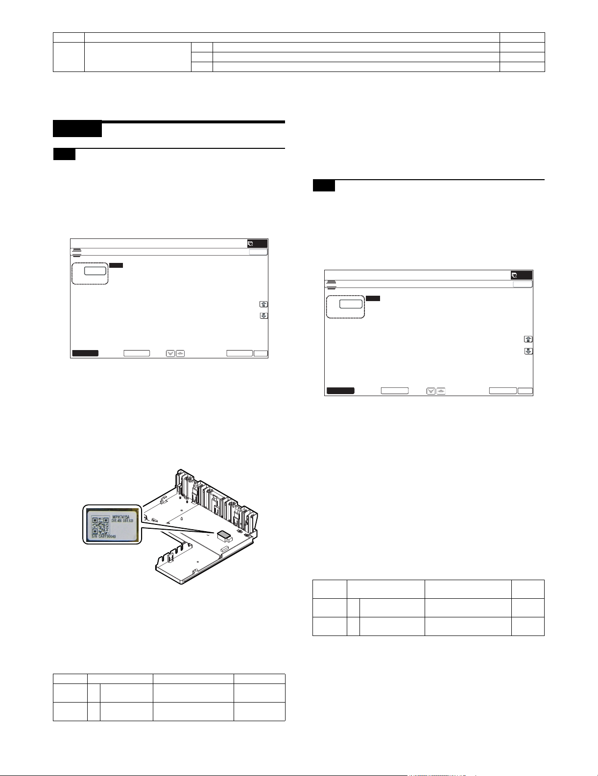
1-B Adjust the developing bias voltage
This adjustment is needed in the following situations:
* When the MC high voltage power PWB is replaced.
* U2 trouble has occurred.
* The PCU PWB has been replaced.
* The EEPROM of the PCU PWB has been replaced.
1) Go through the modes specified in Simulation 8-1.
2) Select an output mode and an item to be adjusted.
3) Enter the adjustment value (specified value) in the middle
speed mode, and press [OK] key.
When [EXECUTE] key is pressed, the voltage entered in the
procedure 3 is outputted for 30sec and the set value is saved.
When [EXECUTE] key is pressed, the output is stopped.
Enter the adjustment value of each mode which is specified on
the label attached on the MC high voltage power PWB.
NOTE: Note that the adjustment value may differ depending on the
MC high voltage power PWB.
Since the adjustment value label is attached on the MC
high voltage PWB, the PWB must be removed in order to
check the adjustment value.
This is a troublesome procedure. Therefore, it is advisable
to put down the adjustment value in advance.
Mode Item/Display Content Setting range
MIDDLE A MIDDLE
SPEED GB_K
LOW A LOW SPEED
GB_K
K charging/grid bias set
value at middle speed
K charging/grid bias set
value at low speed
150 - 850
150 - 850
GBK:XXX
MX-B382/B402 ADJUSTMENTS 4 – 2
Mode Item/Display Content
MIDDLE A MIDDLE SPEED
DVB_K
LOW A LOW SPEED
DVB_K
K developing bias set
value at middle speed
K developing bias set
value at low speed
DVK:XXX
Setting
range
0-600
0-600
Page 30
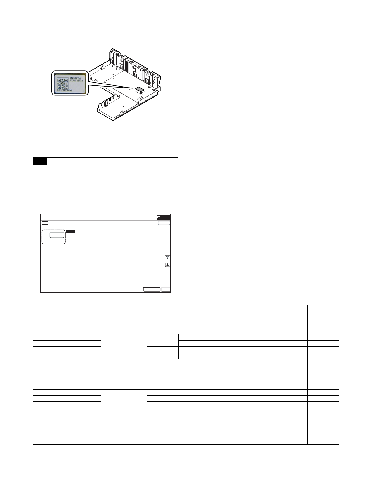
When the adjustment value (specified value) of the middle speed
ǂǂǂ6,08/$7,21ǂǂ12
&/26(
7(67
7+96(77,1*$1'287387
$˖
˷˹
˖7&/2:63(('%:.
$˖
˖7&0,''/(63(('%:.
%˖
˖7&3/$,1%:63;
&˖
˖7&3/$,1%:'3;
'˖
˖7&+($9<%:'3;
)˖
˖7&+($9<%:63;
(˖
˖7&2+3%:
*˖
˖7&(19(/23(%:
+˖
˖7&7+,1%:
,˖
˖7&*/266<%:
-˖
˖7&&/($1,1*
.˖
˖7&&/($1/2:63'
/˖
2.
(;(&87(
mode is set, the adjustment values of the other modes are automatically set according to the middle speed mode setting in a certain relationship.
NOTE: Since the high voltage output cannot be checked with a
digital multi meter in this model, a judgment of the output
must be made by checking the print image quality.
1-C Transfer voltage adjustment
This adjustment is needed in the following situations:
* When the TC high voltage PWB is replaced.
* U2 trouble has occurred.
* The PCU PWB has been replaced.
* The EEPROM of the PCU PWB has been replaced.
1) Go through the modes specified in Simulation 8-6. 2) Select an item to be adjusted.
Enter the adjustment value (specified value), and press [OK]
key.
When [EXECUTE] key is pressed, the voltage entered in the
procedure 3 is outputted for 30sec and the set value is saved.
When [EXECUTE] key is pressed, the output is stopped.
By setting the default value (specified value), the specified output is provided.
Item/Display Content
A TC1 LOW SPEED BW K Primary transfer bias
B TC1 MIDDLE SPEED BW K Middle speed mode 51 - 255 131 2 - 30A13A
reference value
C TC2 PLAIN BW SPX Secondary transfer
D TC2 PLAIN BW DPX Back surface mode 51 - 255 111 –2 - –80A–25A
bias reference value
paper mode
E TC2 HEAVY BW SPX Heavy paper
F TC2 HEAVY BW DPX Back surface mode 51 - 255 93 –2 - –80A–10A
Low speed mode 51 - 255 95 2 - 30A8A
Standard
Front surface mode 51 - 255 111 –2 - –80A–25A
Front surface mode 51 - 255 93 –2 - –80A–10A
mode
Adjustment
range
Default
value
Actual output
setting range
Default value
of actual
output value
G TC2 OHP BW OHP 51 - 255 85 –2 - –80A–8A
H TC2 ENVELOPE BW Envelope 51 - 255 124 –2 - –80A–30A
I TC2 THIN BW Thin paper 51 - 255 111 –2 - –80A–25A
J TC2 GLOSSY BW Gloss paper 51 - 255 72 –2 - –80A–10A
K TC2 CLEANING Cleaning mode 51 - 255 67 –2 - -80A–8A
L TC2 CLEAN LOW SPD Secondary transfer
M TC2 CLEAN MIDDLE SPD Middle speed print mode 0 - 255 16 –100V - 1500V 0V
N TC2 CLEAN CLEANING Cleaning mode 0 - 255 143 –100V - 1500V 800V
cleaning bias
reference value
O PTC LOW SPEED BW PTC current output
P PTC MIDDLE SPEED BW Middle speed mode 0 - 255 133 0A - –700A –300A
reference value
Q CASE VOLT LOW BW PTC case voltage
R CASE VOLT MID BW Middle speed mode 0 - 255 0 0V - –1000V 0V
reference value
S PEEL VOLT LOW BW Separation discharge
T PEEL VOLT MIDDLE BW Middle speed mode 51 - 255 200 –50 - –3000V –2200V
reference value
Low speed print mode 0 - 255 16 –100V - 1500V 0V
Low speed mode 0 - 255 133 0A - –700A –300A
Low speed mode 0 - 255 0 0V - –1000V 0V
Low speed mode 51 - 255 200 –50 - –3000V –2200V
MX-B382/B402 ADJUSTMENTS 4 – 3
Page 31

ǂǂǂ6,08/$7,21ǂǂ12
&/26(
7(67
352&21*$,1$'-8670(17
(;(&87(
3&6B./('$'-
5(*B5%(/70$;
3&6B.'$5.ǂ
5(*B5%(/70,1
3&6B.*51'
5(*B5%(/7',)
3&6B.%(/70$;
3&6B.%(/70,1
5(*B53$7&+.
3&6B.%(/7',)
5(*B5/('$'-
5(*B5'$5.
5(*B5*51'
ǂǂǂ6,08/$7,21ǂǂ12
&/26(
7(67
6(/)35,17%:6(59,&(
$˖
˷˹
˖35,173$77(51
$˖
˖'27'27˚˙,)$
%˖
˖'27'27˚˙,)$
&˖
˖'(16,7<),;(',)$
'˖
˖(;32685(,)$67$1'$5'',7+(5
)˖
˖08/7,&2817
(˖
˖3$3(5&6
*˖
˖'83/(;12
+˖
˖3$3(5ǂ7<3(3/$,1
,˖
2.
(;(&87(
ADJ 2 Image density sensor
adjustment
NOTE: Before executing this adjustment, check to confirm the fol-
lowing items.
* Check to confirm that the image density sensor is clean.
* Check to confirm that the transfer belt is clean and free from
scratches.
NOTE: This adjustment executes automatically at the outset of
registration adjustment operation and process control operation as well as SIM44-2.
Normally, therefore, it is not required to perform this adjustment. It is performed only when the sensor is replaced or
when the adjustment result is checked.
1) Enter SIM44-2 mode.
2) Press [EXECUTE] key.
The image density sensor is automatically adjusted.
After completion of the adjustment, the adjustment result is
displayed and [EXECUTE] key returns to the normal display.
Display/Item Content Range Default
A PCS_K LED ADJ Image density sensor light
emitting quantity
adjustment value
B PCS_K DARK Dark voltage 0 - 255 0
C PCS_K GRND Belt base detection level
when completion of Item A
adjustment
D PCS_K BELT MAX Maximum value of belt
base detection level
E PCS_K BELT MIN Minimum value of belt
base detection level
F PCS_K BELT DIF Belt base detection level
difference
(Item D - Item E)
G REG_R LED ADJ Image density sensor light
emitting quantity
adjustment value
H REG_R DARK Image density sensor dark
voltage
I REG_R GRND Belt base detection level
when completion of Item
G adjustment
J REG_R BELT MAX Maximum value of belt
base detection level
K REG_R BELT MIN Minimum value of belt
base detection level
L REG_R BELT DIF Belt base detection level
difference (Item J - Item K)
M REG_R PATCH (K) Patch detection level for
check
If the adjustment is not completed normally, "ERROR" is displayed.
1 - 255 32
0 - 255 0
0 - 255 0
0 - 255 0
0 - 255 0
1 - 255 32
0 - 255 0
0 - 256 0
0 - 255 0
0 - 255 0
0 - 255 0
0 - 255 0
Error name Error content
Image density sensor
adjustment abnormality
PCS_K LED ADJ error
The target is not reached by 3 times of
retry.
Substrate scan abnormality PCS_K GRND error
Effective difference between the upper
and lower values of the belt substrate
circuit, outside the range
Registration sensor R
adjustment abnormality
REG_R LED ADJ error
The target is not reached by 3 times of
retry.
Registration substrate R
scan abnormality
REG_R GRND error
Effective difference between the upper
and lower values of the belt substrate
circuit, outside the range
Error display Error content
BK_SEN_ADJ
_ERR
BELT_READ
_ERR
Image density
sensor adjustment
abnormality
Transfer belt
surface reading
abnormality
PCS_K LED ADJ error (The
target value is not obtained after
retried three times.)
PCS_K GRND error (The surface
detection level is maximum or the
minimum value difference is
outside a reference range.)
REG_SEN_R
_ADJ_ERR
Sensor adjustment
abnormality
REG_R LED ADJ error (The
target value is not obtained after
retried three times.)
REG_BELT_R
_READ_ERR
Transfer belt
surface reading
abnormality
REG_R GRND error (The
surface detection level is
maximum or the minimum value
difference is outside a reference
range.)
When an error occurs, check the following sections for any
abnormality.
• Image density sensor
• PCU PWB
• Transfer belt (dirt, scratch)
• Transfer belt cleaner
If any abnormality is found, repair and adjust again.
If an error occurs, the adjustment result is not revised.
ADJ 3 Image skew adjustment
(LSU unit)
This adjustment is needed in the following situations:
* When the LSU unit is replaced.
* When the LSU unit is removed from the main unit.
The image skew adjustment (LSU unit) is performed by changing
the parallelism of the LSU unit scan laser beams for the OPC drum.
1) Enter SIM64-2 mode.
Set the set items to the values shown below.
A: 1 B: 1 C: 254 D: 255
MX-B382/B402 ADJUSTMENTS 4 – 4
Page 32

2) Select the tray with A4 (11" x 8.5") paper in it.
K
AB
ǂǂǂ6,08/$7,21ǂǂ12
3$3(5&(17(52))6(76(783
$˖
˷@
˖%.0$*
$˖
˖0$,10)7
%˖
˖0$,1&6
&˖
˖0$,1&6
'˖
˖0$,1&6
)˖
˖0$,1&6
(˖
˖0$,1$'8
*˖
˖68%0)7
+˖
˖68%&6
,˖
˖68%'6.
-˖
˖68%$'8
.˖
˖08/7,&2817
/˖
2.
&/26(
(;(&87(
3) Press [EXECUTE] key.
The check pattern is printed out.
4) Check the printed image for any skew.
There are following two methods of checking the image for any
skew (right angle).
Method 1:
Measure the length of the diagonal lines of the rectangle print
pattern. Check the difference in the length of the diagonal lines
for judgment of good or no good
Method 2:
Compare the right angle of vertical side/horizontal side of the
rectangle print pattern and the right angle sides of A4 (11" x
8.5") paper for judgment of good or no good.
(NOTE)
In the case of Method 2, the right angle of paper to be used
may not be exact. Be sure to check the right angle of paper to
be used in advance.
(Method 1)
a) Measure the length of the diagonal lines of the rectangle
print pattern.
b) Measure the shift distance between vertical side of paper
and side of the rectangle print pattern.
If the above distances (left and right) are 0.5mm or less,
there is no need to adjust.
If not, execute the following procedures.
5) Open the front cabinet, and remove the waste toner box.
6) Turn the LSU unit image skew adjustment screw to adjust.
(When Method 1 is used to check the image for any skew
(right angle) in procedure 4 in advance)
Diagonal line C is longer than diagonal line D: Turn the adjustment screw clockwise.
Diagonal line C is shorter than diagonal line D: Turn the adjustment screw counterclockwise.
(When Method 2 is used to check the image for any skew
(right angle) in procedure 4 in advance)
When the image is skewed in the arrow direction A, turn the
adjustment screw clockwise. When the image is skewed in the
arrow direction B, turn the adjustment screw counterclockwise.
Diagonal line DDiagonal line C
b) Calculate the difference between the measured lengths C
and D of the diagonal lines.
c) Check to insure that the difference between C and D is in
the following range.
C – D = 0.8mm
If the difference between C and D is in the above range, there
is no need to adjust.
(Method 2)
a) Fit the side of A4 or 11" x 8.5" paper to the long side of the
rectangle print pattern.
Comparison line
7) Install the waste toner box, and close the front cabinet.
8) Perform the procedures 3) - 4).
(Perform the procedures 3) - 8) until a satisfactory result is
obtained.)
ADJ 4 Print engine image
magnification ratio adjustment
(Main scanning direction)
(Print engine section)
(Manual adjustment)
This adjustment is needed in the following situations:
* When the LSU (writing) unit is replaced.
* U2 trouble has occurred.
* The PCU PWB has been replaced.
* The EEPROM of the PCU PWB has been replaced.
1) Go through the modes specified in Simulation 50-10.
0.5mm or ress
7(67
Direction BDirection A
2) Select A4 (11" x 8.5") paper.
MX-B382/B402 ADJUSTMENTS 4 – 5
Page 33

3) Press [EXECUTE] key.
ǂǂǂ6,08/$7,21ǂǂ12
3$3(5&(17(52))6(76(783
$˖
˷@
˖%.0$*
$˖
˖0$,10)7
%˖
˖0$,1&6
&˖
˖0$,1&6
'˖
˖0$,1&6
)˖
˖0$,1&6
(˖
˖0$,1$'8
*˖
˖68%0)7
+˖
˖68%&6
,˖
˖68%'6.
-˖
˖68%$'8
.˖
˖08/7,&2817
/˖
2.
&/26(
(;(&87(
The check pattern is printed out.
4) Check that the inside dimension of the printed half tone is 120
0.5mm.
120 0.5mm
If the above requirement is not met, do the following steps.
5) Change the set value of set item A BK-MAG.
When the set value is changed by 1, the dimension is changed
by 0.1mm.
When the set value is increased, the BK image magnification
ratio in the main scanning direction is increased. When the set
value is decreased, the BK image magnification ratio in the
main scanning direction is decreased.
Repeat procedures 2) - 5) until a satisfactory result is obtained.
ADJ 5 Image off-center adjustment
(Print engine section)
This adjustment is needed in the following situations:
* When the LSU is replaced or removed.
* When a paper tray is replaced.
* When the paper tray section is disassembled.
* When [ADJ 4] print engine image magnification ratio (BK) (main
scanning direction) is performed.
* When the manual feed tray is replaced.
* When the manual feed tray is disassembled.
* When the switchback section is disassembled.
* When the registration roller section is disassembled.
* U2 trouble has occurred.
* The PCU PWB has been replaced.
* The EEPROM of the PCU PWB has been replaced.
(Note)
Before execution of this adjustment, check to insure the following
item.
* Check that the print engine image magnification ratio adjustment
(BK) (main scanning direction) has been properly adjusted.
1) Enter SIM50-10 mode.
2) Select a target paper feed tray to be adjusted with the scroll
keys.
Display/Item Content
A BK-MAG Main scan print
magnification ratio BK
B MAIN-MFT Print off center adjustment
value (Manual paper feed)
C MAIN-CS1 Print off center adjustment
value (Tray 1)
D MAIN-CS2 Print off center adjustment
value (Tray 2)
E MAIN-CS3 Print off center adjustment
value (Tray 3)
F MAIN-CS4 Print off center adjustment
value (Tray 4)
G MAIN-ADU Print off center adjustment
value (ADU)
Setting
range
Default
60 - 140 100
1 - 99 65
1 - 99 65
1 - 99 50
1 - 99 50
1 - 99 50
1 - 99 50
NOTE: Before execution of
this adjustment,
check to insure that
the adjustment
items A - F have
been properly
adjusted. If not, this
adjustment cannot
be made properly.
H SUB-MFT Registration
motor ON
I SUB-CS1 Standard
Timing
adjustment
Manual
paper feed
tray
1 - 99 60
1 - 99 60
J SUB-DSK DESK 1 - 99 50
K SUB-ADU ADU 1 - 99 50
L MULTI COUNT Number of print 1 - 999 1
M PAPER MFT Tray
selection
Manual paper
feed
1 - 5 1 2 (CS1)
CS1 Tray 1 2
CS2 Tray 2 3
CS3 Tray 3 4
CS4 Tray 4 5
N DUPLEX YES Duplex
print
NO No 1
Yes 0 - 1 0 1 (NO)
selection
3) Set A4 (11" x 8.5") paper in the paper feed tray selected in procedure 2).
4) Press [EXECUTE] key.
The adjustment pattern is printed.
5) Check that the adjustment pattern image is printed in the correct position.
Measure the dimension of the void area in the front and the
rear frame direction of the adjustment pattern, and check that
all the following conditions are satisfied.
RV
3.0 2.0mm
7(67
RV: REAR VOID AREA
FV: FRONT VOID AREA
RV + FV 8.0mm
RV = 3.0 2.0mm
FV = 3.0 2.0mm
If the above requirement is not met, do the following steps.
MX-B382/B402 ADJUSTMENTS 4 – 6
FV
3.0 2.0mm
Page 34

6) Change the adjustment value.
ǂǂǂ6,08/$7,21ǂǂ12
&/26(
7(67
0$*1,),&$7,21$'-8670(17
$˖
˷˹
˖&&'0$,1
$˖
˖&&'68%
%˖
˖63)0$,1
&˖
˖63)68%
'˖
˖63)%68%
)˖
˖63)%0$,1
(˖
2.
ǂǂǂ6,08/$7,21ǂǂ12
&/26(
7(67
0$*1,),&$7,21$'-8670(17
$˖
˷˹
˖&&'0$,1
$˖
˖&&'68%
%˖
˖63)0$,1
&˖
˖63)68%
'˖
˖63)%68%
)˖
˖63)%0$,1
(˖
2.
Enter the adjustment value and press [OK] key.
When [EXECUTE] key is pressed, the adjustment pattern is
printed.
When the adjustment value is increased, the adjustment pattern is
shifted to the front frame side. When it is decreased, the adjustment pattern is shifted to the rear frame side.
When the set value is changed by 1, the shift distance is changed
by about 0.1mm.
Repeat procedures 5) - 6) until the conditions of procedure 5) are
satisfied.
ADJ 6 Scan image magnification ratio
adjustment
(Document table mode)
This adjustment is needed in the following situations:
* When the copy magnification ratio is not proper.
* When the scanner motor is replaced.
* When the carriage unit is replaced.
* When the scanner unit is replaced.
* When a U2 trouble occurs.
* When the scanner control PWB is replaced.
* When the EEPROM on the scanner control PWB is replaced.
6-A Scan image magnification ratio adjustment
(Main scanning direction) (Document table
mode)
NOTE: It is advisable to set the image magnification ratio adjust-
ment value in the main scanning direction to the default.
If the adjustment value is set to other than the default
value, image quality may be affected.
Changing the adjustment value to other than the default
value is allowed only when a high emphasis is placed on
the accuracy of the image magnification ratio.
1) Place a scale on the document table as shown in the figure
below.
Item/Display Content
A CCD (MAIN) SCAN main scanning
Setting
Default
range
value
1 - 99 50
magnification ratio adjustment
(CCD)
B CCD (SUB) SCAN sub scanning
1 - 99 50
magnification ratio adjustment
(CCD)
3) Make a normal copy and obtain the copy magnification ratio.
4) Check that the copy magnification ratio is within the specified
range (100 1.5%).
If the copy magnification ratio is within the specified range (100
1.5%), the adjustment is completed. If the copy magnification
ratio is not within the specified range, perform the following
procedure.
5) Change the adjustment value of the adjustment item CCD
(MAIN) of SIM48-1.
When the adjustment value is increased, the copy magnification ratio is increased.
When the adjustment value is changed by 1, the copy magnification ratio is changed by about 0.1%.
Repeat the procedures 3) - 5) until the copy magnification ratio is
within the specified range (100 1.5%).
6-B Scan image magnification ratio adjustment
(Sub scanning direction)
(Document table mode)
1) Place a scale on the document table as shown in the figure
below.
2) Enter the simulation 48-1 mode.
2) Enter the simulation 48-1 mode.
Item/Display Content
A CCD (MAIN) SCAN main scanning
B CCD (SUB) SCAN sub scanning
MX-B382/B402 ADJUSTMENTS 4 – 7
magnification ratio
adjustment (CCD)
magnification ratio
adjustment (CCD)
Setting
Default
range
1 - 99 50
1 - 99 50
value
Page 35

3) Make a normal copy and obtain the copy magnification ratio.
ǂǂǂ6,08/$7,21ǂǂ12
&/26(
7(67
0$*1,),&$7,21$'-8670(17
$˖
˷˹
˖&&'0$,1
$˖
˖&&'68%
%˖
˖63)0$,1
&˖
˖63)68%
'˖
˖63)%68%
)˖
˖63)%0$,1
(˖
2.
Copy magnification ratio
(Original dimension - Copy dimension)
Original dimension
100%
(Example 1)
Copy A
(Shorter than
10 20 90
100 110
the original)
2) Make a duplex copy at the normal ratio on A4 paper.
3) Measure the images on the copy paper and the original
images.
original
Scale
(Original)
10 20 90
100 110
(Example 2)
Copy B
(Longer than
10 20 90
100 110
the original)
4) Check that the copy magnification ratio is within the specified
range (100 0.8%).
If the copy magnification ratio is within the specified range (100
0.8%), the adjustment is completed. If the copy magnification
ratio is not within the specified range, perform the following
procedure.
5) Change the adjustment value of the adjustment item CCD
(SUB) of SIM48-1.
When the adjustment value is increased, the copy magnification ratio in the sub scanning direction is increased.
When the adjustment value is changed by 1, the copy magnification ratio is changed by about 0.1%.
Repeat the procedures 3) - 5) until the copy magnification ratio is
within the specified range (100 0.8%).
ADJ 7 Scan image magnification ratio
adjustment (Main/sub scanning
direction) (RSPF mode)
NOTE: To execute this adjustment, the carriage unit must have
been properly installed. To execute this adjustment, the OC
mode adjustment when copying must have been completed.
7-A Scan image magnification ratio adjustment
(Main scanning direction) (RSPF mode)
1) Place the duplex adjustment chart shown below on the document tray of the RSPF.
The adjustment chart is prepared by the following procedures.
Use A4 (11" x 8.5") paper, and put marks on both sides and
both surfaces of the paper at 10mm from each edge.
Paper pass
direction
A4 size
(Both the front surface
and the back surface)
10mm10mm
10 50 100 150 200
copy
10
50 100
4) Obtain the image magnification ratio according to the following
formula:
Image magnification ratio = Original size / Original size x 100
(%)
Image magnification ratio = 99 / 100 x 100 = 99 (%)
If the image magnification ratio is within the specified range
(100 1.5%), there is no need to perform the adjustment.
If it is not within the specified range, perform the following procedures.
5) Enter the SIM48-1 mode.
Item Display Content
C SPF (MAIN) RSPF document front
D SPF (SUB) RSPF document front
E SPFB (MAIN) RSPF document back
F SPFB (SUB) RSPF document back
surface magnification ratio
adjustment (Main scan)
surface magnification ratio
adjustment (Sub scan)
surface magnification ratio
adjustment (Main scan)
surface magnification ratio
adjustment (Sub scan)
6) Select an adjustment item of SPF (MAIN)/SPFB (MAIN) with
the scroll key.
SPF (MAIN): Main scanning direction image magnification
ratio (Front surface)
SPFB (MAIN): Main scanning direction image magnification
ratio (Back surface)
150
200
Setting
range
Default
1 - 99 50
1 - 99 50
1 - 99 50
1 - 99 50
value
MX-B382/B402 ADJUSTMENTS 4 – 8
Page 36
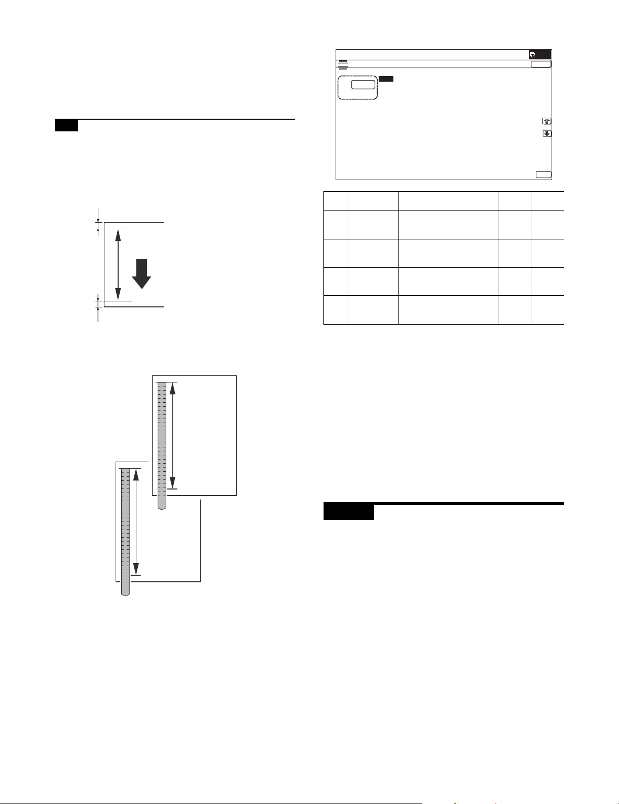
7) Enter an adjustment value with 10-key, and press [OK] key.
ǂǂǂ6,08/$7,21ǂǂ12
&/26(
7(67
0$*1,),&$7,21$'-8670(17
$˖
˷˹
˖&&'0$,1
$˖
˖&&'68%
%˖
˖63)0$,1
&˖
˖63)68%
'˖
˖63)%68%
)˖
˖63)%0$,1
(˖
2.
When the adjustment value is increased, the image magnification ratio is increased.
When the adjustment value is changed by 1, the image magnification ratio is changed by 0.02%.
Repeat the procedures of 2) - 7) until a satisfactory result is
obtained.
7-B Scan image magnification ratio adjustment
(Sub scanning direction) (RSPF mode)
1) Place the duplex adjustment chart shown below on the document tray of the RSPF.
The adjustment chart is prepared by the following procedures.
Use A4 (11" x 8.5") paper, and put marks on both sides and
both surfaces of the paper at 10mm from each edge.
10mm
Paper pass
direction
A4 size
10mm
2) Make a duplex copy at the normal ratio on A4 paper.
3) Measure the images on the copy paper and the original
images.
10
50
100 150
200
10
50
100 150
200
original
250
copy
250
4) Obtain the image magnification ratio according to the following
formula:
Image magnification ratio = Original size / Original size x 100
(%)
Image magnification ratio = 99 / 100 x 100 = 99 (%)
If the image magnification ratio is within the specified range
(100 1.5%), there is no need to perform the adjustment.
If it is not within the specified range, perform the following procedures.
5) Enter the SIM48-1 mode.
Item Display Content
C SPF (MAIN) RSPF document front
surface magnification ratio
adjustment (Main scan)
D SPF (SUB) RSPF document front
surface magnification ratio
adjustment (Sub scan)
E SPFB (MAIN) RSPF document back
surface magnification ratio
adjustment (Main scan)
F SPFB (SUB) RSPF document back
surface magnification ratio
adjustment (Sub scan)
Setting
range
Default
value
1 - 99 50
1 - 99 50
1 - 99 50
1 - 99 50
6) Select an adjustment item of SPF (MAIN)/SPFB (MAIN) with
the scroll key.
SPF (SUB): Sub scanning direction image magnification ratio
(Front surface)
SPFB (SUB): Sub scanning direction image magnification ratio
(Back surface)
7) Enter an image magnification ratio adjustment value with 10key, and press [OK] key.
When the adjustment value is increased, the image magnification ratio is increased.
When the adjustment value is changed by 1, the image magnification ratio is changed by 0.01%.
Repeat the procedures of 2) - 7) until a satisfactory result is
obtained.
ADJ 8 Scan image off-center
adjustment
This adjustment is needed in the following situations:
* When the scanner (reading) section is disassembled.
* When the scanner (reading) unit is replaced.
* When the RSPF section is disassembled.
* When the RSPF unit is installed.
* When the RSPF unit is replaced.
* When a U2 trouble occurs.
* When the scanner control PWB is replaced.
* When the EEPROM on the scanner control PWB is replaced.
MX-B382/B402 ADJUSTMENTS 4 – 9
Page 37

A
B
A=B
ǂǂǂ6,08/$7,21ǂǂ12
&/26(
7(67
25,*,1$/&(17(52))6(76(783
$˖
˷ ˹
˖2&
$˖
˖63)6,'(
%˖
˖63)6,'(
&˖
2.
8-A Scan image off-center adjustment
(Document table mode)
1) Make an adjustment chart. (Draw a line at the center in parallel
with the paper transport direction.)
2) Make a copy of the adjustment chart in the document table
mode.
3) Check the copy image center position.
If A’ - B’ = 4.0mm, the adjustment is not required.
8-B Scan image off-center adjustment
(RSPF mode)
NOTE: To execute this adjustment, the paper off-center must have
been adjusted properly.
1) Make an adjustment chart. (Draw a line at the center of both
surfaces in parallel with the paper transport direction.)
Front surface
A
B
A=B
Back surface
A’ - B’ = 4.0mm
(100%)
If the above condition is not satisfied, perform the following
procedures.
4) Enter the simulation 50-12 mode.
A’
B’
A
B
A=B
2) Set the adjustment chart on the RSPF, and make a copy in the
duplex copy mode.
3) Check the copy image center position.
(Single) If A’ - B’ = 5.0mm, the adjustment is not required.
(Duplex) If A’ - B’ = 5.4mm, the adjustment is not required.
A’
B’
5) Select the adjustment mode OC.
6) Enter the adjustment value with 10-key, and press [OK] key.
When the set value is increased, the main scanning print position is shifted to the front side by 0.1mm.
7) Make a copy, and check the position of the copy image center.
Change the adjustment value and perform procedures 5) - 6)
until the above condition is satisfied.
MX-B382/B402 ADJUSTMENTS 4 – 10
(Single) A’ - B’ = 5.0mm
(Duplex) A’ - B’ = 5.4mm
(100%)
If the above condition is not satisfied, perform the following
procedures.
Page 38

4) Enter the simulation 50-12 mode.
ǂǂǂ6,08/$7,21ǂǂ12
&/26(
7(67
25,*,1$/&(17(52))6(76(783
$˖
˷ ˹
˖2&
$˖
˖63)6,'(
%˖
˖63)6,'(
&˖
2.
ǂǂǂ6,08/$7,21ǂǂ12
3$3(5&(17(52))6(76(783
$˖
˷@
˖%.0$*
$˖
˖0$,10)7
%˖
˖0$,1&6
&˖
˖0$,1&6
'˖
˖0$,1&6
)˖
˖0$,1&6
(˖
˖0$,1$'8
*˖
˖68%0)7
+˖
˖68%&6
,˖
˖68%'6.
-˖
˖68%$'8
.˖
˖08/7,&2817
/˖
2.
&/26(
(;(&87(
ǂǂǂ6,08/$7,21ǂǂ12
&/26(
7(67
/($'('*($'-8670(179$/8(
$˖
˷˹
˖55&$
$˖
˖55&%&6
%˖
˖55&%'6.
&˖
˖55&%0)7
'˖
˖/($'
)˖
˖55&%$'8
(˖
˖6,'(
*˖
˖'(1$
+˖
˖'(1%
,˖
˖)52175($5
-˖
˖2)6(7B2&
.˖
˖6&$1B63(('B2&
/˖
2.
5) Select the adjustment mode.
2) Set A4 (11" x 8.5") paper in the paper feed tray of the adjustment target.
3) Select the paper feed tray of the adjustment target.
4) Press [EXECUTE] key.
The adjustment pattern is printed.
5) Check the adjustment pattern to confirm that the items below
are in the range of the standard values.
Content Standard adjustment value
X Lead edge void area 3.0 1.0mm
Y Rear edge void area 2.0 - 5.0mm
Z1/Z2 FRONT/REAR void area 3.0 2.0mm
Z1
3.0 2.0mm
Item Display Content
A OC Document table image off-
Setting
range
1 - 99 50
Default
value
center adjustment
B SPF(SIDE1) SPF front surface image off-
1 - 99 50
center adjustment
C SPF(SIDE2) SPF back surface image off-
1 - 99 50
center adjustment
6) Enter the adjustment value with 10-key, and press [OK] key.
When the set value is increased, the main scanning print position is shifted to the front side by 0.1mm.
7) Make a copy, and check the position of the copy image center.
Change the adjustment value and perform procedures 4) - 6) until
the above condition is satisfied.
ADJ 9 Print area (Void area)
adjustment
(Print engine section)
This adjustment is needed in the following situations:
* When the LSU is replaced or removed.
* When a paper tray is replaced.
* When the paper tray section is disassembled.
* When the manual feed tray is replaced.
* When the manual feed tray is disassembled.
* When the switchback section is disassembled.
* When the registration roller section is disassembled.
* U2 trouble has occurred.
* The PCU PWB has been replaced.
* The EEPROM of the PCU PWB has been replaced.
NOTE: Before execution of this adjustment, be sure to execute
ADJ 4 Print image magnification ratio adjustment (Print
engine section) in advance.
1) Enter SIM50-10 mode.
7(67
X
3.0 1.0mm
Z2
3.0 2.0mm
Y
2.0 5.0mm
If the above condition is not satisfied, or if it is set to a desired
condition, execute the simulation 50-1.
(Note) Feed paper from all the paper feed trays to confirm.
6) Go through the modes specified in Simulation 50-1.
7) Select the adjustment item DEN A, DEN B, FRONT/REAR with
the scroll key, and enter the adjustment value and press [OK]
key.
Display/Item Content
A Lead
edge
adjustment
B RRCB-CS1 Resist
value
C RRCB-DSK Desk 1 - 99 50
D RRCB-MFT Manual
RRCA Document lead edge
reference position
(OC)
Standard
motor ON
Tray
timing
adjustment
paper
Setting
range
0 - 99 50
1 - 99 60
1 - 99 60
feed
E RRCB-ADU ADU 1 - 99 50
FImage
loss area
setting
G SIDE Side image loss area
value
LEAD Lead edge image
loss area setting
adjustment
0 - 99 30
0 - 99 20
De-
fault
MX-B382/B402 ADJUSTMENTS 4 – 11
Page 39

Display/Item Content
ǂǂǂ6,08/$7,21ǂǂ12
&/26(
7(67
/($'('*($'-8670(179$/8(
$˖
˷˹
˖55&$
$˖
˖55&%&6
%˖
˖55&%'6.
&˖
˖55&%0)7
'˖
˖/($'
)˖
˖55&%$'8
(˖
˖6,'(
*˖
˖'(1$
+˖
˖'(1%
,˖
˖)52175($5
-˖
˖2)6(7B2&
.˖
˖6&$1B63(('B2&
/˖
2.
H Void area
adjustment
I DENB Rear edge void area
DENA Lead edge void area
adjustment
Setting
range
1 - 99 30
1 - 99 30
De-
fault
adjustment
J FRONT/
REAR
K Off-center
OFSET_OC OC document off-
adjus-
FRONT/REAR void
area adjustment
center adjustment
1 - 99 30
1 - 99 50
tment
L Magnifi-
cation
ratio
SCAN_
SPEED_OC
SCAN sub scanning
magnification ratio
adjustment (CCD)
1 - 99 50
correction
MSub
scanning
direction
N DENB-CS1 Tray 1 correction
print area
correction
O DENB-CS2 Tray 2 correction
value
P DENB-CS3 Tray 3 correction
DENB-MFT Manual feed
correction value
value
value
1 - 99 50
1 - 99 50
1 - 99 50
1 - 99 50
value
Q DENB-CS4 Tray 4 correction
1 - 99 50
value
R DENB-ADU ADU correction value 1 - 99 50
When the adjustment value is increased, the void area is
increased. When the adjustment value is decreased, the void
area is decreased.
When the adjustment value is changed by 1, the void area is
changed by 0.1mm.
NOTE: The adjustment value and the actual void area are related
as follows:
Adjustment value/10 = Actual void area
NOTE: When the amount of the rear edge void is different between
each paper feed tray, change the adjustment value of item
M, N, O, P, Q, R (DENB-XXX) in SIM50-1 and adjust.
The adjustment item I (DENB) have a effect on the paper of
all paper feed tray.
Adjustment value of item M, N, O, P, Q, R (DENB-XXX) fine
adjusts to adjustment item I (DENB) for each paper tray.
After execution of the above, perform procedures 1) - 5) to check
that the void area is within the specified range.
Though the lead edge void area adjustment value is proper, if the
lead edge void area is not within the specified range, change the
adjustment value of RRCB-CS1, RRCB-DSK, RRCB-MFT, RRCBADUB (RRCB-XXX) of SIM 50-1.
Repeat the above procedures until a satisfactory result is obtained.
ADJ 10 Copy image position, image
loss adjustment
10-A Copy image position, image loss
adjustment (Document table mode)
This adjustment is needed in the following situations:
* When the scanner (reading) section is disassembled.
* When the scanner (reading) unit is replaced.
* When the LSU is replaced or removed.
* When the registration roller section is disassembled.
* U2 trouble has occurred.
* The PCU PWB has been replaced.
* The EEPROM of the PCU PWB has been replaced.
* The scanner control PWB has been replaced.
* The EEPROM on the scanner control PWB has been replaced.
NOTE: Before executing this adjustment, be sure to confirm that
the ADJ 9 Print area (Void area) adjustment (Print engine
section) has been completed normally.
1) Place a scale on the document table as shown in the figure
below.
Place a scale so that it is in parallel with the scanning direction
and that its lead edge is in contact with the document guide
plate.
Place white paper on the document table so that the scale lead
edge can be seen.
2) Go through the modes specified in Simulation 50-1.
3) Set RRCA, LEAD, and SIDE to the default values.
Display/Item Content
A Lead
edge
adjustment
B RRCB-CS1 Resist
value
C RRCB-DSK Desk 1 - 99 50
D RRCB-MFT Manual
RRCA Document lead edge
reference position
(OC)
Standard
motor ON
Tray
timing
adjustment
paper
Setting
range
0 - 99 50
1 - 99 60
1 - 99 60
feed
E RRCB-ADU ADU 1 - 99 50
FImage
loss area
setting
G SIDE Side image loss area
value
H Void area
adjustment
I DENB Rear edge void area
LEAD Lead edge image
loss area setting
adjustment
DENA Lead edge void area
adjustment
0 - 99 30
0 - 99 20
1 - 99 30
1 - 99 30
adjustment
J FRONT/
REAR
K Off-center
OFSET_OC OC document off-
adjust-
FRONT/REAR void
area adjustment
center adjustment
1 - 99 30
1 - 99 50
ment
L Magnifica
tion ratio
correction
SCAN_
SPEED_OC
SCAN sub scanning
magnification ratio
adjustment (CCD)
1 - 99 50
De-
fault
MX-B382/B402 ADJUSTMENTS 4 – 12
Page 40

Display/Item Content
100%
200%
Paper lead
edge
Scale image 3.0mm position
5mm 10mm
5mm
10mm
5mm
10mm
4
32
1
Paper lead edge
Copy area
Image area
Papar lead edge
Shadow image of RSPF
ǂǂǂ6,08/$7,21ǂǂ12
&/26(
7(67
63)6&$11,1*326,7,21$'-8670(17
$872
0$18$/
MSub
scanning
direction
N DENB-CS1 Tray 1 correction
print area
correction
O DENB-CS2 Tray 2 correction
value
P DENB-CS3 Tray 3 correction
QSub
scanning
direction
R DENB-ADU ADU correction value 1 - 99 50
print area
correction
value
DENB-MFT Manual feed
correction value
value
value
value
DENB-CS4 Tray 4 correction
value
Setting
range
1 - 99 50
1 - 99 50
1 - 99 50
1 - 99 50
1 - 99 50
De-
fault
4) Perform the image lead edge reference position adjustment.
Shift from the simulation mode to the copy mode and make a
copy in 100% mode and in 200% mode.
When the adjustment value of RRCA is proper, the lead edge
image from 3.0mm is not copied in either of 100% and 200%
copy scale.
If not, change and adjust the RRCA value.
(Adjust so that the lead edge image from 3.0mm is not copied
in either of different copy magnification ratios.)
Repeat the above procedures until a satisfactory result is
obtained.
When the adjustment value is increased, the image loss is
increased. When the adjustment value is decreased, the
image loss is decreased.
When the adjustment value is changed by 1, the void area is
changed by 0.1mm.
10-B Adjust the original scan start position
(Adjust the scanner read position in RSPF
mode front face scan)
This adjustment is needed in the following situations:
* The scan control PWB has been replaced.
* The EEPROM on the scan control PWB has been replaced.
* The scanner (reading) section has been disassembled.
* The scanner (reading) unit has been replaced.
* U2 trouble has occurred.
* The RSPF section has been disassembled.
* The RSPF unit has been replaced.
This adjustment is intended to adjust the scanner read position in
RSPF-mode scan.
An incorrect adjustment would deviate the scanner stop position
from the required position, thus possibly causing a shadow of the
original table to appear at the leading edge of an image generated
by RSPF mode scan.
1) Make a copy in RSPF mode, and make sure that the printed
image at the leading edge of the copied image is free from
shadows.
5) Image loss adjustment
Display/
When the adjustment item of the image loss below is set to the
default value, it is adjusted to the standard state. If it is not in
the below standard state, or when it is set to a desired value,
change these adjustment items.
Void area: 3.0mm, Image loss: 3.0mm
Item
LEAD Image loss
SIDE Side image
adjustment
Content
Lead edge
image loss
adjustment
loss adjustment
Adjust
ment
range
0 - 99 30 3.0
0 - 99 20 2.0
Standard
De-
adjustment
fault
value
1.0mm
1.0mm
MX-B382/B402 ADJUSTMENTS 4 – 13
If the printed image at the leading edge of the copied image
contains a shadow of the original table, then do the following
steps.
2) Go through the modes specified in Simulation 53-8. Select the
[MANUAL] mode.
3) Enter the adjustment value and press the [OK] key.
<<Description of adjustment display>>
Set
Item Display item Description
A ADJUST VALUE RSPF scan position
adjustment
Default
range
1 - 99 70
value
• When the set value is increased, the distance from the home
position to the RSPF scan position is increased.
Page 41

• When the set value is changed by 1, the scan position is
F
L
R
FACE
BACK
R
T
F
L
T
Front surface
Back surface
Draw arrows.
Draw arrows.
Put the position
marks.
Put the position
marks.
&/26(
$˖
˷˹
˖6,'(
$˖
˖6,'(
%˖
˖/($'B('*(6,'(
&˖
˖)5217B5($56,'(
'˖
˖/($'B('*(6,'(
)˖
˖75$,/B('*(6,'(
(˖
˖)5217B5($56,'(
*˖
˖75$,/B('*(6,'(
+˖
˖2)6(7B63)
,˖
˖2)6(7B63)
-˖
˖6&$1B63(('B63)
.˖
˖6&$1B63(('B63)
/˖
2.
Paper lead edge
Copyimage
Image loss
3.0 1.0mm
The paper lead edge mustbe alignedwith
theimagelead edge.
changed by 0.1mm.
• Repeat the procedures of 1) - 3) until a satisfactory result is
obtained.
• NOTE: After execution of this adjustment, be sure to
execute ADJ 10C Copy image position, image loss
adjustment (RSPF mode).
10-C Copy image position, image loss
adjustment (RSPF mode)
1) Prepare the adjustment chart.
The adjustment chart can be made by the following procedures.
Use A4 (11" x 8.5") paper and draw arrow marks vertically and
horizontally on the front and the back surfaces.
At the same time, put marks of the lead edge, the trail edge,
the front end, and the rear end as well as the identification
marks of the front surface and the back surface.
2) Enter the SIM50-6 mode.
ǂǂǂ6,08/$7,21ǂǂ12
7(67
/($'('*($'-8670(179$/8(63)
Item/Display Content
CImage
loss
LEAD_EDGE
(SIDE1)
amount
setting
D FRONT_REAR
SIDE1
(SIDE1)
Setting
Front surface lead
edge image loss
amount setting
Front surface side
image loss amount
Default
range
value
0 - 99 20
0 - 99 20
setting
E TRAIL_EDGE
(SIDE1)
Front surface rear
edge image loss
0 - 99 30
amount setting
FImage
loss
amount
setting
G FRONT_REAR
SIDE2
LEAD_EDGE
(SIDE2)
(SIDE2)
Back surface lead
edge image loss
amount setting
Back surface side
image loss amount
0 - 99 20
0 - 99 20
setting
H TRAIL_EDGE
(SIDE2)
Back surface rear
edge image loss
0 - 99 30
amount setting
I OFSET_SPF1 SPF front surface
1 - 99 50
document offcenter adjustment
J OFSET_SPF2 SPF back surface
1 - 99 50
document offcenter adjustment
K SCAN_SPEED_SPF1 RSPF document
1 - 99 50
front surface
magnification ratio
(Sub scan)
L SCAN_SPEED_SPF2 RSPF document
1 - 99 50
back surface
magnification ratio
(Sub scan)
(Lead edge image loss adjustment)
1) Set the lead edge image loss adjustment values (LEAD EDGE
(SIDE1/SIDE2)) on the front surface and the back surface to
the following values.
(Standard set value)
LEAD EDGE(SIDE 1):
20 Lead edge image loss set value (Front surface)
LEAD EDGE(SIDE 2):
20 Lead edge image loss set value (Back surface)
(When the set value is increased, the lead edge image loss is
increased.)
(Change for change in the set value: 0.1mm/step)
2) Make a duplex copy in 100% in the RSPF mode. Check to
confirm that the lead edge image loss is within 3.0 1.0mm on
the front surface and the back surface. The paper lead edge
must be aligned with the presumed image lead edge.
Item/Display Content
A SIDE1 Front surface
document scan
position adjustment
B SIDE2 Back surface
(CCD)
document scan
position adjustment
(CCD)
Setting
range
Default
value
1 - 99 50
1 - 99 50
If the above condition is not satisfied, perform the following
procedure.
MX-B382/B402 ADJUSTMENTS 4 – 14
Page 42
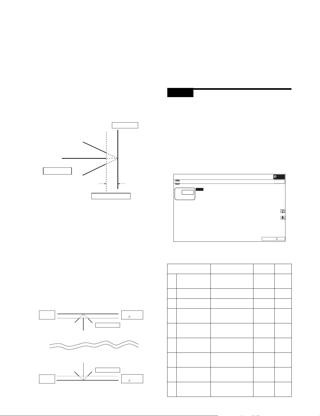
3) Enter the adjustment value of SIDE1/SIDE2 with 10-key, and
ǂǂǂ6,08/$7,21ǂǂ12
&/26(
7(67
/($'('*($'-8670(179$/8(35,17(5
$˖
˷˹
˖'(1&
$˖
˖'(1%
%˖
˖)52175($5
&˖
˖'(1%0)7
'˖
˖'(1%&6
)˖
˖'(1%&6
(˖
˖'(1%&6
*˖
˖'(1%&6
+˖
˖'(1%$'8
,˖
˖08/7,&2817
-˖
˖3$3(5&6
.˖
˖'83/(;12
/˖
(;(&87(
2.
press [OK] key.
Adjust so that the paper lead edge is aligned with the presumed image lead edge.
SIDE1:
Front surface document lead edge scan position adjustment
SIDE2:
Back surface document lead edge scan position adjustment
(When the adjustment value is increased, the print image position is shifted to the delaying direction for the paper.)
(Change for change in the set value: 0.1mm/step)
Perform the procedures of 2) - 3) until a satisfactory result is
obtained.
(Rear edge image loss adjustment)
1) Make a duplex copy in 100% in the RSPF mode. Check to
confirm that the rear edge image loss is 2.0 - 5.0mm on the
front surface and the back surface.
Paper rearedge
Copyimage
2) Enter the adjustment value of FRONT/REAR (SIDE 1)/
FRONT/REAR (SIDE 2), and press [OK] key.
FRONT/REAR (SIDE 1) Front/Rear image loss adjustment
value (Front surface)
FRONT/REAR (SIDE 2) Front/Rear image loss adjustment
value (Back surface)
(When the adjustment value is increased, the front/rear image
loss is increased.)
(Change for change in the adjustment value: 0.1mm/step)
Perform the procedures of 1) - 2) until a satisfactory result is
obtained.
ADJ 11 Print lead edge image position
adjustment (Printer mode)
(Print engine section)
This adjustment is needed in the following situations:
* When the registration roller section is disassembled.
* When the LSU is replaced or removed.
* U2 trouble has occurred.
* The PCU PWB has been replaced.
* The EEPROM of the PCU PWB has been replaced.
NOTE: This adjustment is performed by the user to increase the
lead edge image position (standard value: 3mm).
1) Enter the simulation 50-5 mode.
Image loss 2.0 -5.0mm
If the above condition is not satisfied, perform the following
procedure.
2) Enter the adjustment value of TRAIL EDGE (SIDE1/SIDE2)
with 10-key, and press [OK] key.
TRAIL EDGE (SIDE 1): Rear edge image loss adjustment
value (Front surface)
TRAIL EDGE (SIDE 2): Rear edge image loss adjustment
value (Back surface)
(When the adjustment value is increased, the rear edge image
loss is increased.)
(Change for change in the set value: 0.1mm/step)
Perform the procedures of 1) - 2) until a satisfactory result is
obtained.
(Front/rear frame direction image loss adjustment)
1) Make a duplex copy in 100% in the RSPF mode. Check to
confirm that the image losses on the front frame side and the
rear frame side are 2.0 2.0mm on the front surface and the
back surface.
Paper F
sideedge
Paper R
sideedge
Copyimage
Copyimage
Image loss
2.02.0mm
Image loss
2.02.0mm
If the above condition is not satisfied, perform the following
procedure.
2) Select the set item K with the scroll key, and enter the value
corresponding to the paper feed tray with A4 (11" x 8.5") paper
in it.
Display/Item Content
A DEN-C Printer lead edge
image position
adjustment
B DEN-B Rear edge void area
adjustment
C FRONT/REAR FRONT/REAR void
area adjustment
D DENB-MFT Manual feed rear edge
void area adjustment
correction value
E DENB-CS1 Tray 1 rear edge void
area adjustment
correction value
F DENB-CS2 Tray 2 rear edge void
area adjustment
correction value
G DENB-CS3 Tray 3 rear edge void
area adjustment
correction value
H DENB-CS4 Tray 4 rear edge void
area adjustment
correction value
I DENB-ADU ADU rear edge void
area adjustment
correction value
Setting
range
Default
1 - 99 30
1 - 99 30
1 - 99 30
1 - 99 50
1 - 99 50
1 - 99 50
1 - 99 50
1 - 99 50
1 - 99 50
MX-B382/B402 ADJUSTMENTS 4 – 15
Page 43

Display/Item Content
J MULTI COUNT Number of print 1 - 999 1
K PAPER MFT Tray
L DUPLEX YES Duplex
selection
CS1 Tray 1 2
CS2 Tray 2 3
CS3 Tray 3 4
CS4 Tray 4 5
print
NO No 1
selection
Manual
paper feed
Yes 0 - 1 0 1 ( N O )
Setting
range
1 - 5 1 2 (CS1)
Default
3) Press [EXECUTE] key.
The adjustment pattern is printed.
4) Measure the distance from the paper lead edge the adjustment
pattern to the image lead edge.
Standard adjustment value: 3.0 2.0mm
3.0 2.0mm
If an adjustment is required, perform the following procedures.
5) Select the adjustment target of the paper feed mode adjustment item DENC with the scroll key.
6) Enter the adjustment value and press [OK] key.
When [EXECUTE] key is pressed, the adjustment pattern is
printed.
When the adjustment value is increased, the distance from the
paper lead edge to the image lead edge is increased. When
the adjustment value is decreased, the distance is decreased.
When the set value is changed by 1, the distance is changed
by about 0.1mm.
Perform the procedures 4) - 6) until a satisfactory result is
obtained.
ADJ 12 Copy density and gradation
adjustment
(1) Note before execution of the copy density and gradation
adjustment
* After completion of this adjustment, the printer density and gra-
dation adjustment must be executed.
* Requisite conditions before execution of the copy density and
gradation adjustment
Before execution of the copy density and gradation adjustment,
check to insure that the adjustments which affect the copy density adjustment have been completed.
The importance levels of them are shown below.
(The following items affect the copy density and gradation
adjustment, and must be checked and adjusted before execution of the image quality adjustments.)
1) The following adjustment items must be adjusted properly.
(The following items affect the copy density and gradation
adjustment, but it is not required to adjust them frequently.
When, however, a trouble occurs, check and adjust them.)
1) The following items must be adjusted properly.
Job
No
ADJ 1Adjusting high
voltage values
ADJ 12CCD gamma adjustment (CCD calibration) 63-3
Adjustment item list Simulation
ADJ 1AAdjust the main charger
grid voltage
ADJ 1BAdjust the developing
bias voltage
ADJ 1CTransfer voltage
adjustment
8-2
8-1
8-6
(Relationship between the servicing job contents and the copy
density and gradation adjustment)
Note that the preliminary jobs before execution of the copy density
and gradation adjustment depend on the machine status and the
servicing conditions.
Follow the flowchart of the copy density and gradation adjustment
procedures depending on the actual conditions.
There are following four, major cases.
1) When installing
2) When a periodic maintenance is performed.
3) When a repair, an inspection, or a maintenance is performed.
(When a consumable part is replaced.)
4) When an installation, a repair, or inspection is performed.
(Without replacement of a consumable part)
(2) Copy density and gradation check
(Note)
Before checking the copy density and gradation, be sure to execute
the following jobs.
* Execute the high density image correction (Process correction)
forcibly. (SIM 44-6)
* Execute the half-tone image correction forcibly. (SIM 44-26)
(Method)
Make a copy of the gray test chart (UKOG-0162FCZZ) and a copy
of the servicing color test chart (UKOG-0326FCZZ/UKOG0326FC11), and check that they are proper.
• Note for checking the copy mode density and gradation
To check the density and gradation, use the gray test chart
(UKOG-0162FCZZ). Set the copy density level to "Manual 3" in
the Text/Printed Photo mode (Manual).
In addition, all the adjustments in the user adjustment mode must
be set to the default (center).
[Check with the gray test chart (UKOG-0162FCZZ)]
In the copy density check with the gray test chart, check to insure
the following conditions.
Patch 2 is
slightly copied.
12345678910 W
Patch 3 is copied.
Patch 1 is not copied.
SHARP gray chart
SHARP GRAY CHART
Job
No
ADJ 2Image density
sensor adjustment
Adjustment Item List Simulation
ADJ 2AImage density sensor
adjustment
44-2
MX-B382/B402 ADJUSTMENTS 4 – 16
Page 44
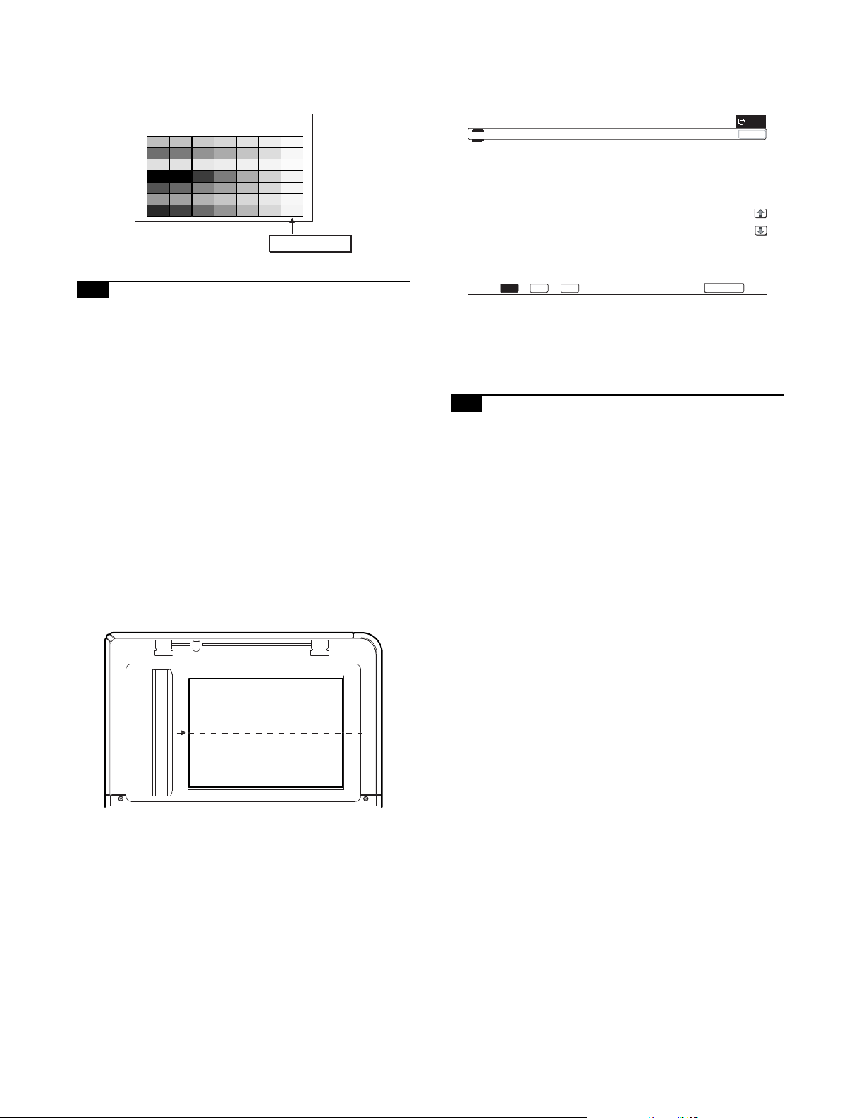
[Check with the servicing color test chart (UKOG-0326FCZZ/
ǂǂǂ6,08/$7,21ǂǂ12
&/26(
7(67
6&$11(5&2/25%$/$1&($872$'-8670(17
(;(&87(
2&
&&&555
000***
<<<%%%
%*5
2&
UKOG-0326FC11)]
In the copy check with the servicing color test chart, check to insure
the following conditions.
Serviceman char t (Color patch section)
Patch 7 is slightly copied or
not copied.
2) Enter the SIM 63-3 mode and press [EXECUTE] key.
The automatic operation is started. During the adjustment,
[EXECUTE] is highlighted. After completion of the adjustment,
[EXECUTE] returns to the normal display.
12-A CCD gamma adjustment (CCD calibration)
This adjustment is needed in the following situations:
* When the carriage unit is replaced.
* When a U2 trouble is occurred.
* When the scanner control PWB is replaced.
* When the EEPROM on the scanner control PWB is replaced.
(1) Note before adjustment
1) Check that the table glass, No. 1, 2, 3 mirrors, and the lens
surface are free from dirt and dust.
(If there is some dust and dirt, wipe and clean with alcohol.)
2) Check to confirm that the patches in BK1 and BK2 arrays of
the SIT chart (UKOG-0280FCZZ or UKOG-0280FCZ1) are
free from dirt and scratches.
If they are dirty, clean them.
If they are scratched or streaked, replace with new one.
(2) Adjustment procedures
1) Set the SIT chart (UKOG-0280FCZZ or UKOG-0280FCZ1) to
the center reference position on the left rear frame side of the
document table.
Set the chart so that the lighter density side of the patch is on
the left side.
NOTE: Since the SIT chart (UKOG-0280FCZZ or UKOG-0280FC
Z1) is easily discolored by sunlight (especially ultraviolet
rays) and humidity and temperature, put it in a bag (such
as a dark file) and store in a dark place of low temperature
and low humidity.
12-B Copy density and gradation adjustment
(Auto adjustment)
This adjustment is needed in the following situations:
* When a consumable part (developer, OPC drum, transfer belt) is
replaced.
* The carriage unit has been replaced.
* When the scanner (reading) section is disassembled.
* When the scanner (reading) unit is replaced.
* U2 trouble has occurred.
* When the MFP PWB is replaced.
* When the EEPROM on the MFP PWB is replaced.
* The scanner control PWB has been replaced.
* The EEPROM on the scanner control PWB has been replaced.
a. General
The copy density and gradation adjustment (auto adjustment) is
used to adjust the copy density and gradation automatically by
SIM46-24 or the user program.
(When this adjustment is executed, the density and gradation
adjustments of all the copy modes are revised.)
If the SIT chart is not available, execute SIM 63-5 to set the
CCD gamma to the default. In this case, however, the adjustment accuracy is lower when compared with the adjustment
method using the SIT chart.
NOTE: Check to insure that the SIT chart (UKOG-0280FCZZ or
UKOG-0280FCZ1) is in close contact with the document
table.
UKOG-0280FCZZ is equivalent to UKOG-0280FCZ1.
There are following two modes in the auto adjustment.
1) Auto copy density and gradation adjustment by the serviceman (SIM 46-24 is used.)
2) Auto copy density and gradation adjustment by the user (The
user program mode is used.)
The auto adjustment by the user is provided to reduce the
number of service calls.
It is used by the user to reset the copy density and gradation to
the normal levels when any trouble occurs in the copy density
and gradation.
When, however, the machine has a fatal problem or when the
machine environment is greatly changed, this function does
not work effectively.
On the other hand, the auto adjustment by the serviceman
functions to recover the normal copy density and gradation
though the machine environment is greatly changed. If the
machine has a fatal problem, repair and adjust it for obtaining
the normal copy density and gradation.
To perform the adjustment, the above difference must be fully
understood.
MX-B382/B402 ADJUSTMENTS 4 – 17
Page 45

b. Note for execution of the copy density and gradation
ǂǂǂ6,08/$7,21ǂǂ12
&/26(
7(67
(1*,1(+$/)721($872$'-8670(1702'(5(*8/$5
(;(&87(
35(66>(;(&87(@72352&21(;(&87,21$1'35,177+(7(673$7&+
3/($6(86(63(&,),('7<3(2)$25h6,=(3$3(5
)257+,6$'-8670(17
adjustment (Auto adjustment)
1) The print engine section must have been adjusted properly.
2) The CCD gamma adjustment must have been adjusted properly.
3) When setting the adjustment pattern on the document table in
the copy density and gradation automatic adjustment procedures, place 5 sheets of white paper on the adjustment pattern
in order to prevent back copying and adverse effects of paper
wrinkles as far as possible. Also note that the adjustment pattern should be placed to the center reference.
4) The scan image off-center adjustment and the engine image
off-center adjustment must have been properly adjusted.
c. Adjustment procedure
(Auto copy density and gradation adjustment by the serviceman)
Flowchart of the auto copy density and gradation adjustment by the serviceman (SIM46-24)
Start
Execute ADJ12B (Auto copy density and gradation adjustment).
Enter the SIM46-24 mode, and select A4R (11 x 8.5"R) paper.
Press [EXECUTE] key. (The adjustment pattern is printed.)
Set the adjustment pattern on the document table.
Press [EXECUTE] key.
(The adjustment pattern is scanned, and the adjustment is automatically performed to print the check pattern.)
1) Enter the SIM 46-24 mode.
Check the printed check pattern for any streaks or unclear copy.
The adjustment check pattern of the copy mode is printed out. (*1)
Press [OK] key, and the initial setting of the half tone image correction
is automatically performed.
Cancel SIM46-24
Check the density adjustment result.
Use the test chart (UKOG-0162FCZZ) or
(UKOG-0326FCZZ/UKOG-0326FC11) to make a copy in the
Text/Printed Photo mode, and check the density.
Use SIM46-21 to print the check pattern, and check the density.
Are the density at the
satisfactory level?
YES
End
NO
Execute ADJ12C (Manual copy density and
gradation adjustment). (SIM46-21).
*1:
If there is any streak or unclear copy on the
printed check pattern, check the print engine
for any problems.
MX-B382/B402 ADJUSTMENTS 4 – 18
Page 46

2) Press [EXECUTE] key. (A4 or 11" x 8.5" paper is automatically
ǂǂǂ6,08/$7,21ǂǂ12
&/26(
7(67
(1*,1(+$/)721($872$'-8670(1702'(5(*8/$5
3/($6(3/$&(35,17('7(673$7&+21'2&80(17*/$667+(135(66>(;(&87(@
/,*+7$5($$7/()76,'(21'2&80(17*/$66
(;(&87(
ǂǂǂ6,08/$7,21ǂǂ12
&/26(
7(67
(1*,1(+$/)721($872$'-8670(1702'(5(*8/$5
&21),507+($'-867('3$7&+$1'35(66>2.@725(*,67(57+,63$7&+'$7$
2.
ǂǂǂ6,08/$7,21ǂǂ12
&/26(
7(67
(1*,1(+$/)721($872$'-8670(1702'(5(*8/$5
&203/(7('7+,6352&('85(
3/($6(48,77+,602'(
Q (Max)
ABCDEFGH I J KLMNOP
High densityLow density
Patch A must not be copied.
The max density patch is not blurred
Patch C or D slightly copied.
The patch density is identical between patches or not reversed.
The patch density is changed gradually.
selected.)
The patch image (adjustment pattern) is printed out.
3) Set the patch image (adjustment pattern) paper printed in procedure 2) on the document table.
Set the printed patch image (adjustment pattern) on the document table. Place the patch image so that the fine lines are on
the left side in the center reference. At that time, place 5
sheets of white paper on the printed patch image (adjustment
pattern).
Remark:
After pressing [OK] key on the operation panel, the initial setting of the half tone image correction is started. During the
operation, "NOW REGISTERING THE NEW TARGET OF
HALFTONE PROCON." is displayed. This operation takes
several minutes.
After completion of the operation, "PLEASE QUIT THIS
MODE" is displayed.
Do not cancel the simulation until "PLEASE QUIT THIS
MODE" is displayed.
6) Check the density and gradation.
There are following three methods in the density and gradation
check.
(Method 1)
Check to insure that the printed check patch image is within
the following specifications.
4) Press [EXECUTE] key.
The copy adjustment is automatically executed to print the
check patch image. Wait until the operation panel shown in
procedure 5) is displayed.
5) Press [OK] key on the operation panel.
According to data of this adjustment, the initial setting of the
half tone image correction is performed.
The print density must be changed gradually from the lighter
level to the darker level. The density changing direction must
not be reversed.
Patch C or D slightly copied.
Patch A must not be copied.
If there is any abnormality, adjust again.
(Method 2)
Use the gray test chart (UKOG-0162FCZZ) or the service color
test chart (UKOG-0326FCZZ/UKOG-0326FC11) in the Text/
Photo mode (manual) to check the copy density and gradation.
(Refer to the items of the copy density and gradation check.)
If a satisfactory result is not obtained by the automatic copy
density and gradation adjustment, use ADJ12C Manual adjustment (SIM46-21) to adjust.
12-C Copy density and gradation adjustment
(Manual adjustment)
This adjustment is needed in the following situations:
* When a consumable part (developer, OPC drum, transfer belt) is
replaced.
* The carriage unit has been replaced.
* When the scanner (reading) section is disassembled.
* When the scanner (reading) section is replaced.
MX-B382/B402 ADJUSTMENTS 4 – 19
Page 47

* U2 trouble has occurred.
ǂǂǂ6,08/$7,21ǂǂ12
&/26(
7(67
(1*,1(*5$<%$/$1&(0$18$/$'-8670(17>$//&2/25@
$˖
˷˹
˖32,17
$˖
˖32,17
%˖
˖32,17
&˖
˖32,17
'˖
˖32,17
)˖
˖32,17
(˖
˖32,17
*˖
˖32,17
+˖
˖32,17
,˖
˖32,17
-˖
˖32,17
.˖
˖32,17
/˖
2.
(;(&87(
.
Q (Max)
ABCDEFGH I J K LMNOP
High densityLow density
Patch A must not be copied.
The max density patch is not blurred
Patch C or D slightly copied.
The patch density is identical between patches or not reversed.
The patch density is changed gradually.
* When the MFP PWB is replaced.
* When the EEPROM on the MFP PWB is replaced.
* The scanner control PWB has been replaced.
* The EEPROM on the scanner control PWB has been replaced.
a. General
The copy density and gradation adjustment (manual adjustment) is
executed when the above automatic adjustment cannot obtain the
specified range, when a fine adjustment is required, or when a
request for customization is made by the user.
b. Note for the copy density and gradation adjustment
(Manual adjustment)
1) The print engine section must have been properly adjusted.
2) The CCD gamma must have been properly adjusted.
c. Adjustment procedure
Manual copy density and gradation adjustment procedure flowchart
(SIM46-21)
Start
Execute ADJ12C (Manual copy density and gradation adjustment).
(*1)
Enter the SIM46-21 mode, and select A4R (11" x 8.5"R)
paper.
Press [EXECUTE] key.
(The adjustment check pattern is printed.)
1) Enter the SIM46-21 mode.
2) Press [EXECUTE] key. (A4 or 11" x 8.5" paper is automatically
selected.)
The adjustment pattern is printed.
3) Check that the following specification is satisfied or the density
and gradation is satisfactory.
If not, execute the following procedures.
Check the density and gradation of the adjustment
check pattern.
Select a target adjustment level with the scroll key.
Enter the adjustment value with 10-key.
Press [EXECUTE] key.
(The adjustment check pattern is printed.)
Check the density and gradation of the adjustment
check pattern.
Are the density
at the satisfactory
level?
YES
Cancel the SIM46-21 mode.
Perform the initial setting of the half tone image
correction. (SIM44-21)
Check the copy density and gradation adjustment result with the test
chart. (*1)
Use the test char t (UKOG-0162FCZZ) or
(UKOG-0326FCZZ/UKOG-0326FC11) to make a copy in the
Text/Printed Photo mode, and check the density.
Are the density
at the satisfactory
level?
YES
NO
NO
The print density must be changed gradually from the lighter
level to the darker level. The density changing direction must
not be reversed.
Patch C or D slightly copied.
Patch A must not be copied.
If the above conditions are not satisfied, execute the following
procedures.
4) Select the adjustment point to be adjusted with the scroll key.
5) Enter the adjustment value with 10-key and press [OK] key.
The adjustment value is set in the range of 245 - 755 (1 - 999).
When SIM 46-24 is used to adjust the automatic density and
gradation, all the set values of this simulation are set to 500.
To increase the density, increase the adjustment value. To
decrease the density, decrease the adjustment value.
Repeat procedures of 2) - 5) until the condition of 3) is satisfied.
When the overall density is low, or when the density is high
and patch A is copied, use the arrow key to adjust all the
adjustment values of A - Q (MAX) to a same level collectively.
Then, adjust each patch density and gradation individually.
This is an efficient way of adjustment.
6) Check the density and gradation of the adjustment check pattern.
End
*1:
If satisfactory density is not obtained with the adjustment,
check the pr int engine for any problems.
MX-B382/B402 ADJUSTMENTS 4 – 20
Page 48

7) Execute SIM 44-21. (Execute the initial setting of the half tone
ǂǂǂ6,08/$7,21ǂǂ12
&/26(
7(67
+$/)721(352&2167$1'$5'9$/8(5(*,67(5
(;(&87(
728&+>(;(&87(@7+(1(;(&87,2167$57
ǂǂǂ6,08/$7,21ǂǂ12
&/26(
7(67
(;32685($'-8670(17%:>&23<@
$˖
˷˹
˖$872
$˖
˖$872
%˖
˖7(;7
&˖
˖7(;735,17('3+272
'˖
˖35,17('3+272
)˖
˖7(;73+272
(˖
˖3+272*5$3+
*˖
˖0$3
+˖
˖7(;7&23<72&23<
,˖
˖7(;735,17('3+272&23<72&23<
-˖
˖35,17('3+272&23<72&23<
.˖
˖/,*+7
/˖
2.
+,*+
/2:
image correction.)
1) Enter the SIM 46-2 mode.
It takes several minutes to complete the operation. After completion of the operation, "COMPLETE" is displayed.
After completion of the operation, the simulation is canceled.
This procedure is to save the copy density and gradation
adjustment data as the reference data for the half tone correction.
Immediately after execution of ADJ 12C (Copy density and
gradation adjustment (Manual)) with SIM 46-21, be sure to
execute this procedure.
When ADJ 12B (Copy density and gradation adjustment
(Auto)) is executed with SIM 46-24, this procedure is automatically executed.
When [EXECUTE] key is pressed, it is highlighted and the
operation is started.
8) Copy the gray test chart (UKOG-0162FCZZ) or the service
color test chart (UKOG-0326FCZZ/UKOG-0326FC11), or a
user document if necessary, in the Text/Printed Photo mode
(manual) to check the adjustment result again. (Refer to the
item of the copy density and gradation check.)
If the copy density and gradation are not adjusted to the specified level, there may be another cause.
Troubleshoot the cause, and repair or perform proper treatments, and try all the procedures of the print image adjustment
from the beginning.
12-D Copy density and gradation adjustment
(Each copy mode) (Whole adjustment)
(Normally unnecessary to adjust)
This adjustment is needed in the following situations:
* When there is necessity to change copy density of the low den-
sity and high density part at each copy mode individually.
* When there is necessity to change the density gradient of the
copy by each the copy mode individually.
* When there is necessity to change all copy density by each the
copy mode individually.
* U2 trouble has occurred.
* When the MFP PWB is replaced.
* When the EEPROM on the MFP PWB is replaced.
The density and gradation is adjusted in each copy mode individually. Normally individual adjustments are not required. When there
is a request from the user, execute this adjustment.
2) Select the copy mode to be adjusted with the scroll key.
Display/Item Content
A AUTO1 Auto 1 LOW 1 - 99 50
B AUTO2 Auto 2 LOW 1 - 99 50
C TEXT Text LOW 1 - 99 50
D TEXT/PRINTED
PHOTO
Text/Printed
Photo
E TEXT/PHOTO Text/Photograph LOW 1 - 99 50
F PRINTED PHOTO Printed Photo LOW 1 - 99 50
G PHOTOGRAPH Photograph LOW 1 - 99 50
H MAP Map LOW 1 - 99 50
I TEXT
(COPY TO COPY)
J TEXT/PRINTED
PHOTO
(COPY TO COPY)
K PRINTED PHOTO
(COPY TO COPY)
Tex t ( C o p y
document)
Text/Printed
Photo (Copy
document)
Printed Photo
(Copy document)
L LIGHT Light document LOW 1 - 99 50
Setting
range
Default
HIGH 1 - 99 50
HIGH 1 - 99 50
HIGH 1 - 99 50
LOW 1 - 99 50
HIGH 1 - 99 50
HIGH 1 - 99 50
HIGH 1 - 99 50
HIGH 1 - 99 50
HIGH 1 - 99 50
LOW 1 - 99 50
HIGH 1 - 99 50
LOW 1 - 99 50
HIGH 1 - 99 50
LOW 1 - 99 50
HIGH 1 - 99 50
HIGH 1 - 99 50
3) Enter the adjustment value with 10-key and press [OK] key.
When adjusting the copy density on the low density part, select
"LOW" mode and change the adjustment value. When adjusting the copy density on the high density part, select "HIGH"
mode and change the adjustment value.
When the adjustment value is increased, the copy density is
increased. When the adjustment value is decreased, the copy
density is decreased.
4) Make a copy and check the adjustment result.
Switch the simulation mode and the normal copy mode alternately, and adjust and check the adjustment result.
Repeat switching the adjustment mode (SIM 46-2) and the
normal copy mode and changing the adjustment value and
checking the adjustment result until a satisfactory result is
obtained.
To increase the density, increase the adjustment value. To
decrease the density, decrease the adjustment value.
MX-B382/B402 ADJUSTMENTS 4 – 21
Page 49

ǂǂǂ6,08/$7,21ǂǂ12
&/26(
7(67
(;32685(02'(6(783%:$(
02'(
02'(
$(B02'(
˖
5($/7,0(
35(6&$1
6723
$(B6723B&23<
˖
2))
21
$(B6723B)$;
˖
5($/7,0(
35(6&$1
6723
$(B6723B6&$1
˖
62)7
6+$53
1250$/
$(B),/7(5
˖
)8//
3$57
$(B:,'7+
˖
12-E Condition setting of document density
reading operation (exposure) in the auto
copy mode (Normally not required)
Use for setting the condition of read operation (Exposure) for document density in monochrome auto copy mode.
When a copy with correct density is not obtained by type of document, change the setting.
This adjustment is required in the following cases.
* When a copy with correct density is not obtained in auto mode.
* U2 trouble has occurred.
* When the MFP PWB is replaced.
* When the EEPROM on the MFP PWB is replaced.
1) Enter the SIM 46-19 mode.
AE WIDTH PART:
Document density reading area in auto mode is 3 - 7 mm
(leading edge of document) x 100 mm (width). No relationship to PRESCAN MODE
Operation in auto copy mode:
When the density of the document of the read area is light,
output image density is increased by control. When the
density of the document of the read area is dark, output
image density is decreased by control.
Document table/RSPF mode
3to 7mm
AE WIDTH = FULL
Document table mode
2) Set REALTIME, STOP or PRE-SCAN to adjustment item AE
STOP COPY. For contents of each setting item, refer to below.
Change the setting value of "AE WIDTH" item to "FULL" or
"PART", in some cases.
Display/Item Content Set value Default
AE_MODE Auto exposure mode MODE1, MODE2 MODE2
AE_STOP_COPY Auto B/W exposure
Stop (for copy)
AE_STOP_FAX Auto B/W exposure
REALTIME/
STOP
STOP/PRESCAN
ON/OFF ON
Stop (for FAX)
AE_STOP_SCAN Auto B/W exposure
Stop (for scanner)
AE_FILTER Auto exposure filter
setting
REALTIME/
STOP
STOP/PRESCAN
SOFT NORMAL
NORMAL
SHARP
AE_WIDTH AE exposure width FULL PART
PART
NOTE: MODE1: High gamma (Improves the image contrast)
MODE2: Normal gamma
STOP:
Reads the density of 3 - 7 mm area from leading edge of
document, decides the output image density according to
the density of that part. (The output image density is constant at whole area.)
REALTIME:
Reads the density of width of the document one by one,
decides the output image density according to the density
of each part of the document. (The output image density
may be not constant at whole area.)
PRESCAN:
The densities of the all surface of document are once
scanned, and the output image density is determined
according to the average of the scanned densities. (The
output image density is even for all the surface.)
AE WIDTH FULL:
Document density reading area in auto mode is 3 - 7 mm
(leading edge of document) x Document width. No relationship to PRESCAN MODE
100mm
RSPF mode
100mm
3to 7mm
AE WIDTH = PART
3to 7mm
AE WIDTH = PART
Document density detection area
MX-B382/B402 ADJUSTMENTS 4 – 22
Page 50

ǂǂǂ6,08/$7,21ǂǂ12
&/26(
7(67
/,0,72)$(5($&7,216(77,1*
$˖
˷˹
˖&23 <˖2&
$˖
˖&23<˖563)
%˖
˖6&$ 1˖2&
&˖
˖6&$1˖563)
'˖
˖)$;˖563)
)˖
˖)$;˖2&
(˖
2.
ǂǂǂ6,08/$7,21ǂǂ12
&/26(
7(67
%:,0$*(&5($7($'-8670(17%5DWLR
$˖
˷˹
˖55DWLR
$˖
˖*5DWLR
%˖
'()$8/7
$5(<28685("
<(612(;(&87(
12-F Document background density
reproducibility adjustment in the auto copy
mode (Normally unnecessary to adjust)
Use for the reproducibility adjustment of document background
density in auto copy mode.
When there is a desire to no reproducing the document background or reproducing the low density image, adjust this.
This adjustment is required in the following cases.
* When there is a desire not to reproduce the background of the
document. When there is a desire to reproduce the low density
image of the document.
* U2 trouble has occurred.
* When the MFP PWB is replaced.
* When the EEPROM on the MFP PWB is replaced.
* When there is request from the user.
1) Enter the SIM 46-32 mode.
2) Select the adjusting mode "COPY: OC", "COPY: RSPF" with
the scroll key.
3) Enter the adjustment value with 10-key and press [OK] key.
When the adjustment value is increased, reproducibility of the
background and the low density image is increased. When the
adjustment value is decreased, reproducibility of the background and the low density image is decreased.
Display/Item Content
A COPY : FOC Copy mode (for OC) 1 - 250 196
B COPY : RSPF Copy mode (for RSPF) 1 - 250 196
C SCAN : OC Scanner mode (for OC) 1 - 250 196
D SCAN : RSPF Scanner mode (for RSPF) 1 - 250 196
E FAX : OC FAX mode (for OC) 1 - 250 196
F FAX : RSPF FAX mode (for RSPF) 1 - 250 196
Set
value
Default
12-G Color document reproducibility adjustment
in the copy mode
(Normally unnecessary to adjust)
Use to adjust the reproducibility for the red image and the yellow
image when printing color document that included the red/yellow
image in copy mode.
This adjustment is required in the following cases.
* When there is desire to change reproducibility of yellow/red
image in case of making a copy of the color document.
* U2 trouble has occurred.
* When the MFP PWB is replaced.
* When the EEPROM on the MFP PWB is replaced.
1) Enter the SIM 46-37 mode.
2) Select the mode to be adjusted with the scroll key.
Display/Item
(Copy mode)
Content
A R-Ratio Gray making setting (R) 0 - 1000 172
B G-Ratio Gray making setting (G) 0 - 1000 828
Adjustment
range
Default
3) Enter the adjustment value with 10-key.
When [DEFAULT] key is pressed, the value is set to the default
value.
When the adjustment values of the adjustment items A and B
are decreased, the copy density of yellow images is increased.
When the adjustment values are increased, the density is
decreased.
When the adjustment value of the adjustment item A is
decreased and the adjustment value of the adjustment item B
is increased, the copy density of red images is increased.
When the adjustment value of the adjustment item A is
increased and the adjustment value of the adjustment item B is
decreased, the copy density of red images is decreased.
4) Press [EXECUTE] key.
5) Press [YES] key.
6) Make a copy in the Text/Printed Photo copy mode (manual),
and check the copy.
If a satisfactory result is not obtained, return to SIM46-37 and
change the adjustment value.
Repeat the above operation until a satisfactory result is
obtained.
12-H Sharpness adjustment in the auto copy
mode (Normally unnecessary to adjust)
Use for sharpness adjustment of the high density image in auto
copy mode.
This adjustment changes smoothness (asperity) in the image
shade part.
This adjustment is required in the following cases.
* When changing the sharpness of copy image in auto copy mode.
(obtain crispy image) (decreases moire)
* When there is desire to improving smoothness in the image
shade part (for decrease of asperity)
* U2 trouble has occurred.
* When the MFP PWB is replaced.
* When the EEPROM on the MFP PWB is replaced.
MX-B382/B402 ADJUSTMENTS 4 – 23
Page 51

1) Enter the SIM 46-60 mode.
$˖
ǂǂǂ6,08/$7,21ǂǂ12
&/26(
7(67
(1*,1(0$;,080'(16,7<$'-8670(1702'(
$˖
˷˹
˖.˄(1$%/(ǂ˖',6$%/(˅
$˖
˖%/$&.ǂ0$;ǂ7$5*(7
%˖
2.
&/26(
2.
˷
ǂǂ12
˹
ǂǂǂ6,08/$7,21
7(67
&2/25$87202'(ǂ),/7(5
ǂ$'-8670(17
˖6&5((1),/7(5/(9(/
$˖
˖$87202'(),/7(5/(9(/
%˖
˖&2/25&23<
&˖
˖&2/25&23<
'˖
˖6,1*/(&2/25
(˖
˖&2/25&23<
)˖
˖&2/25&23<
*˖
˖%:&23<
+˖
˖&2/25386+
,˖
˖%:386+
-˖
&0<21
.21
&0<21
&0<21
.21
21
5*%21
21
$872
&(17(5
2) Select the mode to be adjusted with the scroll key.
Display/Item Content Setting range Default NOTE
A SCREEN
FILTER LEVEL
H Sharpness (filter) adjustment of dot
pattern image in auto copy mode
L Soft emphasis 2
AUTO Auto 3
B AUTOMODE
FILTER LEVEL
B/W COPY OFF Soft filter applying setting in
C
COLOR
D
PUSH:RGB
B/W PUSH OFF Soft filter applying setting to image in
E
SOFT Sharpness (filter) adjustment of Text/
CENTER CENTER 2
HIGH HIGH 3
Printed Photo/Text Document image in
auto copy mode
monochrome copy mode
ON ON 1
OFF Soft filter applying setting to image in
push scan color mode
ON ON 1
push scan monochrome mode
ON ON 1
3) Input numeric value corresponding to sharpness level (filter
process mode).
• Adjustment item A:
When selecting AUTO, filter is selected according to dot pattern state automatically and adjusts sharpness.
Input small numeric value to obtain crispy image. Input large
numeric value to decrease moire.
• Adjustment item B:
Select HIGH to obtain clear images. Select SOFT to reduce
moire.
• Adjustment item C - J:
When setting ON, smoothness in the image shade part
improves by applying soft filter. (asperity decreases)
Strong emphasis 1 3 (Auto) Apply to auto copy mode
only
SOFT 1 2 (CENTER) Apply to auto copy mode
(Text/Printed Photo/Text
Document)
OFF 0 1 (ON)
OFF 0 1 (ON)
OFF 0 1(ON)
4) Press [OK] key.
5) Make a copy and check the copy image.
If a satisfactory result is not obtained, return to the SIM 46-60 mode
and change the adjustment value.
Repeat the above procedures until a satisfactory result is obtained.
12-I Copy high density part density correction
If a tone gap occurs on part of high density in copy mode, or if there
is necessity to increase the density of the part of high density,
change the setting.
This setting normally not required. When, however, there are case
of following, change the setting.
* When a tone gap occurs on part of high density.
* When there is necessity to increase the density of the part of
high density.
* The carriage unit has been replaced.
* U2 trouble has occurred.
* When the MFP PWB is replaced.
* When the EEPROM on the MFP PWB is replaced.
setting (Prevents against tone gap)
(Normally unnecessary to adjust)
MX-B382/B402 ADJUSTMENTS 4 – 24
a. Adjustment procedure
1) Enter the SIM 46-23 mode.
Page 52

2) Select the item A with the scroll key.
ǂǂǂ6,08/$7,21ǂǂ12
&/26(
7(67
$˖
˷ ˹
$˖
%˖
&˖
'˖
)˖
(˖
2.
ǂǂǂ6,08/$7,21ǂǂ12
&/26(
7(67
(1$%/,1*2)$8720$7,&*5$<&$/,%5$7,21
$˖
˷˹
˖<(612
$˖
2.
Display/Item Content
AK
(0: ENABLE
1: DISABLE)
0 K engine maximum
density correction mode
Enable
1 K engine maximum
density correction mode
Disable
BBLACK MAX
TAR GE T
Scanner target value for
BLACK maximum density
correction
Setting
range
Default
0 - 1 1
0 - 999 500
* If a tone gap occurs on part of high density, set 0 to item A.
The density of high density part decreases. However, the
tone gap is better.
* In case of more increase of the density on high density part,
set 1 to item A.
The tone gap may occur in high density part.
3) Press [OK] key.
NOTE: When the value of item B (MAX TARGET) is changed, the
density in the high density section is changed.
If these values is changed, be sure to execute the copy
density and gradation adjustment ADJ 12B. (Auto adjustment)
12-J Copy density and gradation adjustment in
the RSPF mode (Normally unnecessary to
adjust)
This setting normally not required. When, however, there are case
of following, change the setting.
* When copy in RSPF mode differs from copy in document table
mode.
* When copy density in RSPF mode is low or too high.
* When the RSPF unit is replaced.
* When the RSPF unit is disassembled.
* The carriage unit has been replaced.
* U2 trouble has occurred.
* When the MFP PWB is replaced.
* When the EEPROM on the MFP PWB is replaced.
a. Adjustment procedure
1) Enter the SIM 46-9 mode.
(;32685($'-8670(1763)
˖&23</2:
˖6&$1/2:
˖)$;/ 2:
˖&23<+,*+
˖6&$1+,*+
˖)$;+ ,*+
2) Select the mode to be adjusted with the scroll key.
When adjusting density on low density part, select "A (COPY
LOW)". When adjusting density on high density part, select "D
(COPY HIGH)".
Item/Display Content
A COPY : LOW RSPF copy mode exposure
adjustment (Low density side)
B SCAN : LOW RSPF scanner mode exposure
adjustment (Low density side)
C FAX : LOW PSPF FAX mode exposure
adjustment (Low density side)
D COPY : HIGH RSPF copy mode exposure
adjustment (High density side)
E SCAN : HIGH RSPF scanner mode exposure
adjustment (Low density side)
F FAX : HIGH RSPF FAX mode exposure
adjustment (High density side)
Setting
range
1 - 99 45
1 - 99 45
1 - 99 45
1 - 99 48
1 - 99 48
1 - 99 48
De-
fault
3) Enter the adjustment value with 10-key.
In case of increase of image density, input large numeric
value. Or in case of diluting the image density, input small
numeric value.
4) Press [OK] key.
5) Make a copy in the single copy mode and check the copy.
Repeat the above procedures until a satisfactory result is obtained.
12-K Auto copy density and gradation
adjustment by the user (Copy auto
adjustment enable setting and adjustment)
a. General
In the user program mode, the user can execute the auto calibration (auto adjustment of the copy density and gradation).
This adjustment is to set Enable/Disable of the above user operation with SIM 26-53.
NOTE: This setting must be set to ENABLE only when the user's
understanding on the automatic adjustment of the copy
density and gradation and the user's operational ability are
judged enough to execute the adjustment.
When set to ENABLE, give enough explanations on the
operating procedures, notes, and operations to the user.
This adjustment is required in the following cases.
* U2 trouble has occurred.
* When the MFP PWB is replaced.
* When the EEPROM on the MFP PWB is replaced.
* When the PCU PWB is replaced.
* When the EEPROM of the PCU PWB is replaced.
b. Setting procedure
1) Enter the SIM 26-53 mode.
2) Select ENABLE or DISABLE with 10-key.
When disabling, set to "0" (NO). When enabling, set to "1"
(Yes).
3) Press [OK] key.
MX-B382/B402 ADJUSTMENTS 4 – 25
Page 53

When set to DISABLE, the menu of the user auto calibration (automatic adjustment of copy density and gradation) is not displayed in
the user program mode.
(Auto calibration by the user (Auto copy density and gradation
adjustment))
1) Enter the system setting mode.
2) Enter the copy setting mode.
3) Press the auto calibration key.
4) Press [EXECUTE] key.
The patch image (adjustment pattern) is printed out.
5) Set the patch image (adjustment pattern) printed in procedure
4) on the document table.
Set the patch image so that the light density area is on the left
side in the center reference.
At that time, place 5 sheets of white paper on the above patch
image (adjustment pattern).
6) Press [EXECUTE] key, and the copy adjustment is executed
automatically. After completion of the adjustment, the display
returns to the original operation screen.
ADJ 13 Printer density and gradation
adjustment
(1) Note before execution of the printer density and gradation
adjustment
(Requisite condition before execution of the printer density and gradation adjustment)
Before execution of the printer density and gradation adjustment,
the copy density and gradation adjustment must have been completed properly.
(This adjustment is required in the following cases.)
* Basically same as when the copy density and gradation adjust-
ment is required.
* After the copy density and gradation adjustment.
(2) Printer density and gradation check
(Note)
Before checking the copy density and gradation, be sure to execute
the following procedures in advance.
* Execute the high density image correction (Process correction)
forcibly. (SIM 44-6)
* The half-tone image correction is forcibly executed. (SIM 44-26)
(Method 1)
Execute SIM 64-5 to print the print test pattern.
Set each set value to the default and press [EXECUTE] key. The
print test pattern is printed.
The print density must be changed gradually from the lighter level
to the darker level. The density changing direction must not be
reversed.
(Method 2)
Use SIM67-25 to print the adjustment sheet to check that the
adjustment is proper or not.
PRINTER CALIBRATION
The max density patch is not blurred
The patch density is identical between patches or not reversed.
Patch A or B slightly printed
ABCDEFGH I J K LMNOP
Q (Max)
The patch density is changed gradually.
High densityLow density
The print density must be changed gradually from the lighter level
to the darker level. The density changing direction must not be
reversed.
Patch A or B slightly printed.
13-A Printer density and gradation adjustment
(Auto adjustment)
a. General
The printer density and gradation adjustment (auto adjustment) is
used to adjust the printer density and gradation automatically by
SIM67-24 or the user program.
(When this adjustment is executed, the printer density and gradation adjustments of all the print modes are revised.)
There are following two modes in the auto adjustment.
1) Auto printer density and gradation adjustment by the serviceman (SIM 67-24 is used.)
2) Auto printer density and gradation adjustment by the user (The
user program mode is used.)
The auto printer density and gradation adjustment by the user
is provided to reduce the number of service calls.
It is used by the user to reset the printer density and gradation
to the normal levels when any trouble occurs in the printer density and gradation.
When, however, the machine has a fatal problem or when the
machine environment is greatly changed, this function does
not work effectively.
On the other hand, the auto printer density and gradation
adjustment by the serviceman functions to recover the normal
printer density and gradation though the machine environment
is greatly changed. If the machine has a fatal problem, repair
and adjust it for obtaining the normal printer density and gradation.
To perform the adjustment, the above difference must be fully
understood.
b. Note for execution of the printer density and gradation
adjustment (Auto adjustment)
1) The copy density and gradation adjustment must have been
completed properly.
2) When setting the adjustment pattern on the document table in
the automatic density and gradation adjustment procedures,
place 5 sheets of white paper on the adjustment pattern in
order to prevent back copying and adverse effects of paper
wrinkles as far as possible. Also note that the adjustment pattern should be placed to the center reference.
3) The scan image off-center adjustment and the engine image
off-center adjustment must have been properly adjusted.
MX-B382/B402 ADJUSTMENTS 4 – 26
Page 54

c. Adjustment procedure
(Auto printer density and gradation adjustment by the serviceman)
Printer density and gradation adjustment (Automatic adjustment) procedure
flowchart (SIM67-24)
Start
Execute ADJ13A (Printer density and gradation adjustment)
(Automatic adjustment).
Enter the SIM67-24 mode, and select A4 (11" x 8.5")
paper.
Press [EXECUTE] key.
(The adjustment pattern is printed.)
Set the adjustment pattern on the document table.
Press [EXECUTE] key. (The adjustment pattern is
scanned, and the adjustment is automatically performed to print the check pattern.)
Check the printed check pattern for any streaks or
unclear copy. (*3)
Press [OK] key. (The initial setting of the half tone
image correction is automatically performed.)
Cancel SIM67-24.
Check the self print check pattern to check the
printer density and gradation adjustment. (*1)
Use SIM64-5 to print the self print
check pattern, and check the printer
density and gradation.
Are the printer
density and gradation
at the satisfactory
level?
YES
End
NO
Execute ADJ13B (Printer density and gradation
adjustment) (Manual adjustment). (SIM67-25) (*2)
*1:
If the initial setting of the half tone image correction is not
properly adjusted, satisfactory printer density and gradation
cannot be obtained. In this case, check the print engine for
any problems.
*2:
If satisfactory printer density and gradation are not obtained
with ADJ13B (Printer density and gradation adjustment)
(Manual adjustment) (SIM67-25), check the print engine for
any problems.
*3:
If there is any streak or unclear copy on the printed check
pattern, check the print engine for any problems.
MX-B382/B402 ADJUSTMENTS 4 – 27
Page 55

1) Enter the SIM 67-24 mode.
ǂǂǂ6,08/$7,21ǂǂ12
&/26(
7(67
(;(&87(
PRINTER C A LIBRATION
ǂǂǂ6,08/$7,21ǂǂ12
&/26(
7(67
(;(&87(
ǂǂǂ6,08/$7,21ǂǂ12
&/26(
7(67
2.
ǂǂǂ6,08/$7,21ǂǂ12
&/26(
7(67
Q (Max)
ABCDEFGH I J K LMNOP
High densityLow density
Patch A must not be copied.
The max density patch is not blurred
Patch C or D slightly copied.
The patch density is identical between patches or not reversed.
The patch density is changed gradually.
5) Press [OK] key on the operation panel.
35,17(5(1*,1(+$/)721($872$'-8670(1702'(5(*8/$5
35(66>(;(&87(@72352&21(;(&87,21$1'35,177+(7(673$7&+
3/($6(86(63(&,),('7<3(2)$25h6,=(3$3(5
)257+,6$'-8670(17
2) Press [EXECUTE] key. (A4 or 11" x 8.5" paper is automatically
selected.)
The patch image (adjustment pattern) is printed out.
3) Set the patch image (adjustment pattern) paper printed in procedure 2) on the document table.
Set the printed patch image (adjustment pattern) on the document table. Place the patch image so that the fine lines are on
the left side in the center reference. At that time, place 5
sheets of white paper on the printed patch image (adjustment
pattern).
35,17(5(1*,1(+$/)721($872$'-8670(1702'(5(*8/$5
&21),507+($'-867('3$7&+$1'35(66>2.@725(*,67(57+,63$7&+'$7$
Remark:
After pressing [OK] key, the initial setting of the half tone image
correction is started. During the operation, "NOW REGISTERING THE NEW TARGET OF HALFTONE" is displayed. This
operation takes several minutes.
After completion of the operation, "PLEASE QUIT THIS
MODE" is displayed.
Do not cancel the simulation until "PLEASE QUIT THIS
MODE" is displayed.
35,17(5(1*,1(+$/)721($872$'-8670(1702'(5(*8/$5
&203/(7('7+,6352&('85(
3/($6(48,77+,602'(
4) Press [EXECUTE] key.
35,17(5(1*,1(+$/)721($872$'-8670(1702'(5(*8/$5
3/($6(3/$&(35,17('7(673$7&+21'2&80(17*/$667+(135(66>(;(&87(@
/,*+7$5($$7/()76,'(21'2&80(17*/$66
The printer density and gradation adjustment is automatically
executed and prints the check patch image. Wait until the
operation panel shown in the procedure 5) is displayed.
MX-B382/B402 ADJUSTMENTS 4 – 28
6) Check the printer density and gradation.
There are three methods to check the printer density and gradation.
(Method 1)
Check to insure that the printed check patch image is within
the following specifications.
The print density must be changed gradually from the lighter
level to the darker level. The density changing direction must
not be reversed.
Patch C or D slightly copied.
Patch A must not be copied.
If there is any abnormality, adjust again.
Page 56

(Method 2)
Use SIM67-25 to print the adjustment check sheet.
PRINTER CALIBRATIONPRINTER CALIBRATION
c. Adjustment procedure
Manual printer density and gradation adjustment procedure flowchart
(SIM67-25)
The max density patch is not blurred
The patch density is identical between patches or not reversed.
Patch A or B slightly printed
ABCDEFGH I J K LMNOP
Q (Max)
The patch density is changed gradually.
High densityLow density
The print density must be changed gradually from the lighter
level to the darker level. The density changing direction must
not be reversed.
(Method 3)
Use SIM64-5 to print the print test pattern, and check the density and gradation.
Set each set value to the default and press [EXECUTE] key.
The print test pattern is printed out.
If a satisfactory result is not obtained with the above procedure, perform the manual density and gradation adjustment
(ADJ 13B).
13-B Printer density and gradation adjustment
(Manual adjustment)
This adjustment is needed in the following situations:
* When the copy density and gradation adjustment is required.
Basically same as when the copy density and gradation adjustment is required.
* After the copy density and gradation adjustment.
a. General
The printer density and gradation adjustment (manual adjustment)
is executed when the above automatic adjustment cannot obtain
the specified range, when a fine adjustment is required, or when a
request for customization is made by the user.
If the adjustment state is improper, it is advisable to execute the
automatic adjustment in advance then execute this adjustment for
efficiency.
b. Note for the printer density and gradation adjustment
(Manual adjustment)
1) After execution of the copy density and gradation adjustment.
Start
Execute ADJ13B (Printer density and gradation adjustment
(Manual adjustment)). (*1)
Enter the SIM67-25 mode, and select A4R
(11 " x 8.5"R) paper.
Press [EXECUTE] key.
(The adjustment pattern is printed.)
Check the density and gradation of the
adjustment check pattern.
Select a target adjustment density level with the
scroll key.
Enter the adjustment value with 10-key.
Press [EXECUTE] key.
(The adjustment pattern is printed.)
Check the density and gradation of the
adjustment check pattern.
Are the density
at the satisfactory
level?
YES
Cancel the SIM67-25 mode.
Check the self print check pattern to check the printer
density adjustment result. (*2)
Use SIM64-5 to print the self print
check pattern, and check the printer
density.
NO
MX-B382/B402 ADJUSTMENTS 4 – 29
Are the printer
density and gradation
at the satisfactory
level?
YES
End
*1:
If satisfactory density is not obtained with the
adjustment, check the print engine for any
problems.
NO
Page 57

1) Enter the SIM 67-25 mode.
ǂǂǂ6,08/$7,21ǂǂ12
&/26(
7(67
$˖
˷˹
$˖
%˖
&˖
'˖
)˖
(˖
*˖
+˖
,˖
-˖
.˖
/˖
2.
.
(;(&87(
ǂǂǂ6,08/$7,21ǂǂ12
&/26(
7(67
35,17(5+,*+/,*+7$'-8670(17
$˖
˷˹
˖$3$7&+,1387
$˖
2.
ǂǂǂ6,08/$7,21ǂǂ12
&/26(
7(67
(1*,1(0$;,080'(16,7<$'-8670(1702'()2535,17(5
$˖
˷˹
˖.(1$%/(',6$%/(
$˖
˖%/$&.0$;7$5*(7
%˖
2.
35,17(5(1*,1(*5$<%$/$1&(0$18$/$'-8670(173*
˖32,17
˖32,17
˖32,17
˖32,17
˖32,17
˖32,17
˖32,17
˖32,17
˖32,17
˖32,17
˖32,17
˖32,17
2) Press [EXECUTE] key. (A4 or 11" x 8.5" paper is automatically
selected.)
The adjustment pattern is printed.
3) Check that the following specification is satisfied or the density
and gradation is satisfactory.
If not, execute the following procedures.
PRINTER CALIBRATIONPRINTER CALIBRATION
The max density patch is not blurred
The patch density is identical between patches or not reversed.
Patch A or B slightly printed
The patch density is changed gradually.
13-C Printer density and gradation adjustment
(low density part density and gradation
adjustment) (Normally unnecessary to
adjust)
This procedure is to adjust image density of low density area in
printer mode.
Adjust to reproduction (not reproduction) setting of the low density
image.
This adjustment is required in the following cases.
* When reproduction of low density image is required. When repro-
duction of low density image is not required, conversely.
* U2 trouble has occurred.
* When the MFP PWB is replaced.
* When the EEPROM on the MFP PWB is replaced.
* When there is request from the user.
1) Enter the SIM 67-36 mode.
ABCDEFGH I J K LMNOP
Q (Max)
High densityLow density
The print density must be changed gradually from the lighter
level to the darker level. The density changing direction must
not be reversed.
Patch A or B slightly printed.
If, however, an adjustment is made by a request from the user,
there is no need to follow the above standard.
4) Select the adjustment point to be adjusted with the scroll key.
5) Enter the adjustment value with 10-key and press [OK] key.
The adjustment value is set in the range of 0 - 255 (1 - 99).
When SIM 67-24 is used to adjust the automatic density and
gradation, all the set values of this simulation are set to 50.
To increase the density, increase the adjustment value. To
decrease the density, decrease the adjustment value.
Repeat procedures of 2) - 5) until the condition of 3) is satisfied.
When the overall density is low, or when the density is high
and patch A is copied, use the arrow key to adjust all the
adjustment values of A - Q (MAX) to a same level collectively.
Then, adjust each patch density individually. This is an efficient
way of adjustment.
6) Cancel SIM 67-25.
7) Use SIM 64-5 to print the print test pattern and check the density and gradation.
2) Enter the adjustment value and press the [OK] key.
In case of increase of the image density on low density part,
increase the adjustment value. In case of increase of the
image density on low density part, increase the adjustment
value. For diluting the image density on low density part,
decrease the adjustment value.
13-D Printer high density part density correction
setting (High density part tone gap
countermeasure) (Normally unnecessary to
the setting change)
This procedure is to adjust image density of low density area in
printer mode.
This setting normally not required. When, however, there are case
of following, change the setting.
* When a tone gap occurs on part of high density.
* When there is necessity to increase the density of the part of
high density.
* The carriage unit has been replaced.
* U2 trouble has occurred.
* When the MFP PWB is replaced.
* When the EEPROM on the MFP PWB is replaced.
a. Adjustment procedure
1) Enter the SIM 67-34 mode.
MX-B382/B402 ADJUSTMENTS 4 – 30
Page 58

2) Select the item A, B with the scroll key.
ǂǂǂ6,08/$7,21ǂǂ12
&/26(
7(67
(1$%/,1*2)$8720$7,&*5$<&$/,%5$7,212)35,17(5
$˖
˷˹
˖<(612
$˖
2.
Display/Item Content
AK
(0:ENABLE
1: DISABLE)
B BLACK MAX
TAR GE T
0 K engine maximum
density correction
mode Enable
1 K engine maximum
density correction
mode Disable
Scanner target value for
BLACK maximum density
correction
Setting
range
0 - 999 500
Default
0 - 1 1
* If a tone gap occurs on part of high density, set 0 to item A.
The density of high density part decreases. However, the tone
gap is better.
* In case of more increase of the density on high density part, set 1
to item A.
The tone gap may occur in high density part.
(NOTE) If the setting values of item B is changed, density of the
high density part is changed.
When these values are changed, be sure to perform the printer
density and gradation adjustment. (Automatic adjustment)
13-E Auto density and gradation adjustment by
the user (Printer auto adjustment ENABLE
setting and adjustment)
a. General
In the user program mode, the user can execute the auto calibration (auto adjustment of the copy density and gradation).
This adjustment is to set Enable/Disable of the above user operation with SIM 26-54.
CAUTION: This setting must be set to ENABLE only when the
This adjustment is required in the following cases.
* U2 trouble has occurred.
* The PCU PWB has been replaced.
* The EEPROM of the PCU PWB has been replaced.
* When the MFP PWB is replaced.
* When the EEPROM on the MFP PWB is replaced.
b. Setting procedure
1) Enter the SIM 26-54 mode.
user's understanding on the automatic adjustment of
the printer density and gradation and the user's operational ability are judged enough to execute the adjustment.
When set to ENABLE, give enough explanations on the
operating procedures, notes, and operations to the
user.
2) Select ENABLE or DISABLE with 10-key.
When disabling, set to "0" (NO). When enabling, set to "1"
(Yes).
3) Press [OK] key.
When set to DISABLE, the menu of the user auto density and gradation (automatic adjustment of printer density) is not displayed in
the user program mode.
(Auto calibration by the user (Auto adjustment))
1) Enter the system setting mode.
2) Enter the printer setting mode.
3) Press the auto calibration key.
4) Press [EXECUTE] key.
The patch image (adjustment pattern) is printed out.
5) Set the patch image (adjustment pattern) printed in procedure
4) on the document table.
Set the patch image to the center reference position so that the
light density area is on the left side in the center reference.
At that time, place 5 sheets of white paper on the above patch
image (adjustment pattern).
6) Press [EXECUTE] key, and the copy density and gradation
adjustment is executed automatically. After completion of the
adjustment, the display returns to the original operation
screen.
13-F Copy/Printer density and gradation
adjustment (Automatic adjustment)
This adjustment is needed in the following situations:
* When a consumable part (developer, OPC drum, transfer belt) is
replaced.
* When the carriage unit is replaced.
* When the scanner (reading) section is disassembled.
* When the scanner (reading) unit is replaced.
* U2 trouble has occurred.
* When the MFP PWB is replaced.
* When the EEPROM on the MFP PWB is replaced.
* The scanner control PWB has been replaced.
* The EEPROM on the scanner control PWB has been replaced.
a. General
SIM46-74 is used to perform the automatic copy density and gradation adjustment (SIM46-24) and the automatic printer density and
gradation adjustment (SIM67-24) continuously.
Since it is desirable to perform the copy adjustment (automatic
adjustment) before the automatic printer density and gradation
adjustment, it is advisable to perform the adjustment in this mode.
This mode is also advisable to effectively perform both of the automatic copy density and gradation adjustment (SIM46-24) and the
automatic printer density and gradation adjustment (SIM67-24). It
saves considerable time when compared with performing each of
the auto copy/printer density and gradation adjustment individually.
b. Note for execution of the copy/printer density and
gradation adjustment (Automatic adjustment for each
dither)
1) When setting the adjustment pattern on the document table in
the automatic adjustment procedures, place 5 sheets of white
paper on the adjustment pattern in order to prevent back copying and adverse effects of paper wrinkles as far as possible.
Also note that the adjustment pattern should be placed to the
center reference.
2) The scan image off-center adjustment and the engine image
off-center adjustment must have been properly adjusted.
MX-B382/B402 ADJUSTMENTS 4 – 31
Page 59

c. Adjustment procedures
ǂǂǂ6,08/$7,21ǂǂ12
&/26(
7(67
(;(&87(
ǂǂǂ6,08/$7,21ǂǂ12
&/26(
7(67
(;(&87(
(Auto density and gradation adjustment by the serviceman)
Copy/printer density and gradation adjustment (Automatic adjustment)
(SIM46-74) procedure flowchart
Start
Execute ADJ13F (Copy density and gradation/Printer density and gradation adjustment
(automatic density)). (SIM46-74)
(Copy density and gradation adjustment (automatic adjustment)
Enter the SIM46-74 mode, and select A4 (11" x 8.5") paper.(Automatic selection)
Press [EXECUTE] key.(The adjustment pattern is printed.)
Set the adjustment pattern on the document table. Press [EXECUTE] key.
(The adjustment pattern is scanned, and the adjustment is automatically performed to
print the check pattern.)
Check the printed check pattern for any streaks or unclear copy. (*2)
(Printer density and gradation adjustment (Automatic adjustment))
Press [EXECUTE] key.(The adjustment pattern is printed.)
Set the adjustment pattern on the document table. Press [EXECUTE] key.
(The adjustment pattern is scanned, and the adjustment is automatically performed to
print the check pattern.) (*1)
Check the printed check pattern for any streaks or unclear copy. (*2)
Press [OK] key.(The initial setting of the half tone image correction is automatically
performed.) (*1)
Cancel SIM46-74.
Check the copy density and gradation adjustment result.
Use the test chart (UKOG-0326FCZZ/UKOG-0326FC11) to make a copy in the Text
/Printed Photo mode, and check the copy density and gradation.
Use SIM46-21 to print the check pattern, and check the density and gradation.
Are the density and gradation
at the specified level?
YES
NO
PCL pr inter?
YES
Check the density and gradation adjustment result with the self print check pattern.
Use SIM67-25 to print the self print
check pattern, and check the density
and gradation.
Use SIM64-5 to print the self print check
pattern, and check the printer density and
gradation.
Are the density
and gradation at
the specified level?
End
NO
NO
YES
Execute ADJ12C (Copy density and
gradation adjustment) (Manual
adjustment). (SIM46-21/44-21) (*1)
Execute ADJ13B (Printer density and
gradation adjustment)
(Manual adjustment). (SIM67-25)
1) Enter the SIM46-74 mode. 2) Press [EXECUTE] key.
The high density process control is performed, and the copy
patch image (adjustment pattern) is printed out. (A4 or 11" x
(1*,1($872$'-8670(176(59,&(
35(66>(;(&87(@72352&21(;(&87,21$1'35,177+(7(673$7&+
3/($6(86(63(&,),('7<3(2)$25h6,=(3$3(5
)257+,6$'-8670(17
8.5" paper is automatically selected.)
(1*,1($872$'-8670(176(59,&(
352&21(;(&87,1*
*1:
If satisfactory density and gradation
are not obtained with ADJ12C
(Copy density and gradation
adjustment) (Manual adjustment)
(SIM46-21/44-21), check the print
engine for any problems.
*2:
If there is any streak or unclear
copy on the pr inted check pattern,
check the print engine for any
problems.
MX-B382/B402 ADJUSTMENTS 4 – 32
Page 60
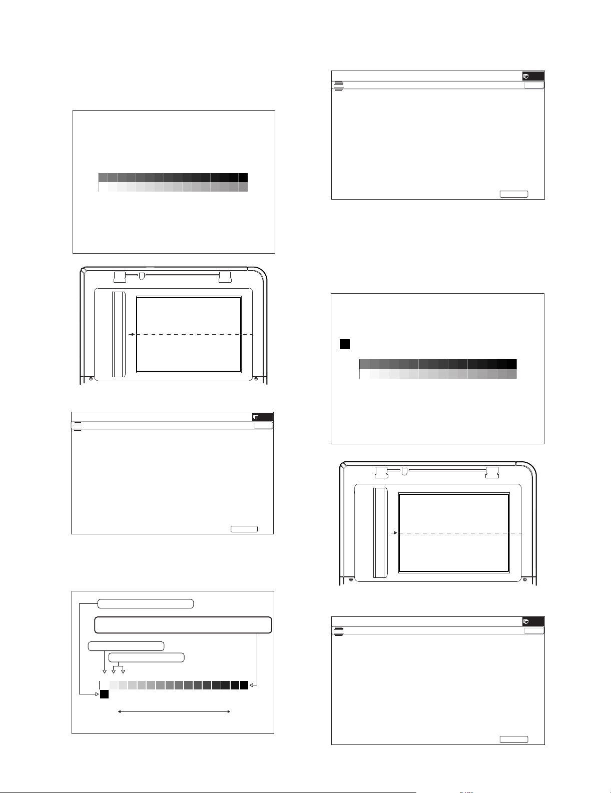
3) Set the patch image (adjustment pattern) paper printed in pro-
ǂǂǂ6,08/$7,21ǂǂ12
&/26(
7(67
(;(&87(
Q (Max)
ABCDEFGH I J KLMNOP
High densityLow density
Patch A must not be copied.
The max density patch is not blurred
Patch C or D slightly copied.
The patch density is identical between patches or not reversed.
The patch density is changed gradually.
ǂǂǂ6,08/$7,21ǂǂ12
&/26(
7(67
(;(&87(
PRINTER C ALIBRATIO N
ǂǂǂ6,08/$7,21ǂǂ12
&/26(
7(67
(;(&87(
cedure 2) on the document table.
Set the printed patch image (adjustment pattern) on the document table. Place the patch image so that the fine lines are on
the left side in the center reference. At that time, place 5
sheets of white paper on the printed patch image (adjustment
pattern).
5) Press [EXECUTE] key.
The printer patch image (adjustment pattern) is printed out.
(A4 or 11" x 8.5" paper is automatically selected.)
(1*,1($872$'-8670(176(59,&(
&21),507+($'-3$7&+$1'35(66>(;(&87(@72$'-2)5(*,675$7,21(;(
$1'35,177+(7(673$7&+
3/($6(86(63(&,),('7<3(2)$25h6,=(3$3(5
)257+,6$'-8670(17
6) Set the patch image (adjustment pattern) paper printed in procedure 5) on the document table.
Set the printed patch image (adjustment pattern) on the document table. Place the patch image so that the fine lines are on
the left side in the center reference. At that time, place 5
sheets of white paper on the printed patch image (adjustment
pattern).
4) Press [EXECUTE] key.
(1*,1($872$'-8670(176(59,&(
3/($6(3/$&(
7+(35,17('7(673$7&+21'2&80(17*/$667+(135(66>(;(&87(@
/,*+7$5($$7/()76,'(21'2&80(17*/$66
The copy density and gradation adjustment is automatically
executed and prints the check patch image.
If there is any streak or unclear print on the printed check pattern, check the print engine for any problems.
7) Press [EXECUTE] key.
(1*,1($872$'-8670(176(59,&(
3/($6(3/$&(
7+(35,17('7(673$7&+21'2&80(17*/$667+(135(66>(;(&87(@
/,*+7$5($$7/()76,'(21'2&80(17*/$66
If there is any abnormality, adjust again.
MX-B382/B402 ADJUSTMENTS 4 – 33
Page 61

The adjustment (step 1) is automatically performed and the
ǂǂǂ6,08/$7,21ǂǂ12
&/26(
7(67
2.
ǂǂǂ6,08/$7,21ǂǂ12
&/26(
7(67
EXECUTE
EXECUTE
ǂǂǂ6,08/$7,21ǂǂ12
&/26(
7(67
%<3$6675$<$'-8670(17
(;(&87(
0$;326,7,21$'-8670(17
35(66>(;(&87(@7267$57
ǂǂǂ6,08/$7,21ǂǂ12
&/26(
7(67
%<3$6675$<$'-8670(17
(;(&87(
3$5326,7,21$'-8670(17
35(66>(;(&87(@7267$57
ǂǂǂ6,08/ $7,2 1ǂǂ12
&/26(
7(67
%<3$6675$<$'-8670(17
(;(&87(
&203/(7(
Repeat the above procedure to adjust
the A5R width MIN POSITION.
check patch image is printed out.
If there is any streak or unclear print on the printed check pattern, check the print engine for any problems.
PRINTER CALIBRATIONPRINTER CALIBRATION
The max density patch is not blurred
The patch density is identical between patches or not reversed.
Patch A or B slightly printed
The patch density is changed gradually.
ABCDEFGH I J K LMNOP
ADJ 14 Manual paper feed tray paper
size (width) sensor adjustment
This adjustment is needed in the following situations:
* The manual paper feed tray section has been disassembled.
* The manual paper feed tray unit has been replaced.
* U2 trouble has occurred.
* The PCU PWB has been replaced.
* The EEPROM of the PCU PWB has been replaced.
1) Go through the modes specified in Simulation 40-2.
Q (Max)
High densityLow density
If there is any abnormality, adjust again.
8) The initial setting menu of the half tone image correction is displayed. Press [OK] key.
The initial setting of the half tone image correction is performed.
(1*,1($872$'-8670(176(59,&(
&21),507+($'-867('3$7&+$1'35(66>2.@725(*,67(57+,63$7&+'$7$
9) When "COMPLETE THIS PROCEDURE" is displayed, the
adjustment operation is completed. Cancel SIM46-74.
(1*,1($872$'-8670(176(59,&(
&203/(7('7+,6352&('85(
3/($6(48,77+,602'(
NOTE: The adjustment result becomes valid only when the both
adjustments in the copy mode and in the printer mode are
completed.
If, for example, only the copy density and gradation adjustment (auto adjustment) is performed and the simulation is
canceled, the adjustment result is invalid.
10) Check the copy and printer density and gradation.
If a satisfactory result on the print density and gradation is not
obtained with the automatic adjustment, execute the manual
adjustment (SIM 67-25) (ADJ 13B).
MX-B382/B402 ADJUSTMENTS 4 – 34
2) Open the manual paper feed guide to the maximum width position.
Page 62
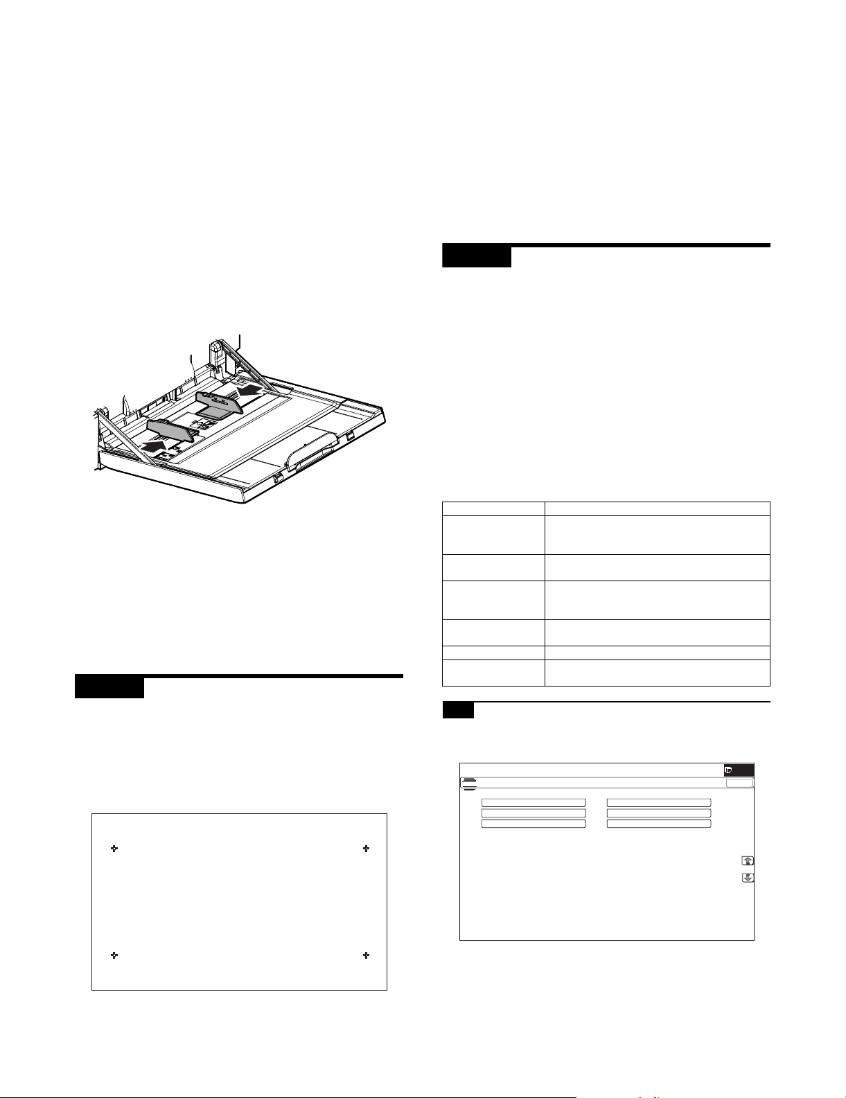
3) Press [EXECUTE] key.
ǂǂǂ6,08/$7,21ǂǂ12
&/26(
7(67
2&$'-
%.0$*$'-
63)$'-
66(78335,17$'-
5(68/7
'$7$
[EXECUTE] key is highlighted. Then it returns to the normal
display.
The maximum width position detection level of the manual
paper feed guide is recognized.
4) Set the manual paper feed guide to the A4R size.
5) Press [EXECUTE] key.
[EXECUTE] key is highlighted. Then it returns to the normal
display.
The A4R size width position detection level of the manual
paper feed guide is recognized.
6) Set the manual paper feed guide to the width for the A5R size.
7) Press [EXECUTE] key.
[EXECUTE] key is highlighted. Then it returns to the normal
display.
Set the manual paper feed guide to the width for the A5R size.
8) Open the manual paper feed guide to the minimum width position.
2) Precisely press the cross mark points (4 positions).
When the cross mark is pressed precisely, a buzzer sounds
and the display is reversed. When all the four points are
pressed and the touch panel adjustment is completed, the display returns to the simulation sub number entry screen.
In case of an error, the display returns to the entry screen
again.
Check to confirm that there is no shift between the display
frame and the detection position when the touch panel is
pressed.
* When pressing the touch panel, never use a sharp tip (such
as a needle or a pin).
ADJ 16 Image loss, void area, image
off-center, image magnification
ratio auto adjustment with
SIM50-28
The following adjustment items can be executed automatically with
SIM50-28.
* ADJ 4 Print image magnification ratio adjustment
(Main scanning direction) (Print engine section)
* ADJ 5 Image off-center adjustment (Print engine section)
* ADJ 6/7 Scan image magnification ratio adjustment
* ADJ 8 Scan image off-center adjustment
* ADJ 9 Print area (void area) adjustment (Print engine section)
* ADJ 10 Copy image position, image loss adjustment
(Menu in SIM50-28 mode)
9) Press [EXECUTE] key.
[EXECUTE] key is highlighted. Then it returns to the normal
display.
The minimum width position detection level of the manual
paper feed guide is recognized.
If the above operation is not completed normally, "ERROR" is
displayed.
When the operation is completed normally, the above data are
saved to the memory and "COMPLETE" is displayed.
ADJ 15 Touch panel coordinate setting
This adjustment is needed in the following situations:
* The operation panel has been replaced.
* U2 trouble has occurred.
* The scanner control PWB has been replaced.
* The EEPROM on the scanner control PWB has been replaced.
1) Enter the SIM 65-1 mode.
Display/Item Content
OC ADJ Image loss off-center sub scanning direction
image magnification ratio adjustment (Document
table mode)
BK-MAG ADJ Main scanning direction image magnification ratio
adjustment
SPF ADJ Image loss off-center sub scanning direction
image magnification ratio adjustment
(RSPF mode)
SETUP/PRINT ADJ Print lead edge adjustment, image off-center
(each paper feed tray, duplex mode) adjustment
RESULT Adjustment result display
DATA Display of data used when an adjustment is
executed
16-A Print image main scanning direction image
magnification ratio automatic adjustment
1) Enter the SIM50-28 mode.
$872,0$*(326,7,21$'-8670(176(59,&(
MX-B382/B402 ADJUSTMENTS 4 – 35
Page 63

2) Select BK-MAG ADJ.
ǂǂǂ6,08/$7,21ǂǂ12
&/26(
7(67
(;(&87(
0)7
&6
ǂǂǂ6,08/$7,21ǂǂ12
&/26(
7(67
(;(&87(
5(35,17
ǂǂǂ6,08/$7,21ǂǂ12
&/26(
7(67
'$7$
5(6&$1
5(35,17
5(75<
2.
ǂǂǂ6,08/$7,21ǂǂ12
&/26(
7(67
2&$'-
%.0$*$'-
63)$'-
66(78335,17$'-
5(68/7
'$7$
ǂǂǂ6,08/$7,21ǂǂ12
&/26(
7(67
/($'
2))6(7
$//
ǂǂǂ6,08/$7,21ǂǂ12
&/26(
7(67
(;(&87(
0)7
&6
$'8
&6
&6
&6
3) Select the paper feed tray with A4 (11" x 8.5") paper in it.
$872,0$*(326,7,21$'-8670(176(59,&(
16-B Image off-center automatic adjustment
(Document table mode)
1) Enter the SIM50-28 mode.
$872,0$*(326,7,21$'-8670(176(59,&(
4) Press [EXECUTE] key.
The adjustment pattern is printed out.
5) Set the adjustment pattern to the center reference position on
the document table.
NOTE: Fit the adjustment pattern correctly with the document
guide.
6) Press [EXECUTE] key.
$872,0$*(326,7,21$'-8670(176(59,&(
3/($6(:$,7
12:(;(&87,1*
2) Select [SETUP/PRINT ADJ].
3) Select [OFFSET].
$872,0$*(326,7,21$'-8670(176(59,&(
(Note)
When [ALL] is selected, the adjustments of the following two
items are performed at a same time.
* [LEAD]: Print image lead edge image position adjustment
* [OFFSET]: Print image off-center adjustment
4) Select a paper feed tray to be adjusted.
Set A4 (11" x 8.5") paper in each paper feed tray in advance.
The following item is automatically adjustment.
* Print image main scanning direction image magnification
ratio
7) Press [OK] key.
The adjustment result becomes valid.
$872,0$*(326,7,21$'-8670(176(59,&(
%.0$*
NOTE: When an error occurs in the automatic adjustment of
SIM50-28, place white paper on the adjustment pattern and
perform the adjustment.
MX-B382/B402 ADJUSTMENTS 4 – 36
$872,0$*(326,7,21$'-8670(176(59,&(
5) Press [EXECUTE] key.
The adjustment pattern is printed out. (Paper is fed from the
selected paper feed tray, and the adjustment pattern of each
paper feed tray is printed out.)
Page 64

6) Set the adjustment pattern to the center reference position on
ǂǂǂ6,08/$7,21ǂǂ12
&/26(
7(67
(;(&87(
5(35,17
ǂǂǂ6,08/$7,21ǂǂ12
&/26(
7(67
'$7$
5(6&$1
5(35,17
5(75<
2.
ǂǂǂ6,08/$7,21ǂǂ12
&/26(
7(67
2&$'-
%.0$*$'-
63)$'-
66(78335,17$'-
5(68/7
'$7$
ǂǂǂ6,08/$7,21ǂǂ12
&/26(
7(67
(;(&87(
0)7
&6
the document table.
NOTE: Fit the adjustment pattern correctly with the document
guide.
7) Press [EXECUTE] key.
16-C Copy lead edge image reference position
adjustment, image off-center, sub scanning
direction image magnification ratio
automatic adjustment
(Document table mode)
1) Enter the SIM50-28 mode.
$872,0$*(326,7,21$'-8670(176(59,&(
$872,0$*(326,7,21$'-8670(176(59,&(
3/($6(:$,7
12:(;8&87,1*
The following item is automatically adjustment.
* Print image lead edge image position adjustment
* Print image off-center adjustment
Perform the procedures of 6) - 7) for the printed adjustment
pattern of each paper feed tray.
8) Press [OK] key.
The adjustment result becomes valid.
$872,0$*(326,7,21$'-8670(176(59,&(
35,17/($'0)7&$6$'8
&$6'6.
35,172))6(70)7&$6&$6$'8
&$6&$6
2) Select [OC ADJ].
3) Select a paper feed tray. Set A4 (11" x 8.5") paper.
$872,0$*(326,7,21$'-8670(176(59,&(
4) Press [EXECUTE] key.
The adjustment pattern is printed out.
5) Set the adjustment pattern on the document table.
NOTE: Fit the adjustment pattern correctly with the document
guide.
NOTE: When an error occurs in the automatic adjustment of
SIM50-28, place white paper on the adjustment pattern and
perform the adjustment.
MX-B382/B402 ADJUSTMENTS 4 – 37
Page 65

6) Press [EXECUTE] key.
ǂǂǂ6,08/$7,21ǂǂ12
&/26(
7(67
(;(&87(
5(35,17
ǂǂǂ6,08/$7,21ǂǂ12
&/26(
7(67
'$7$
5(6&$1
5(35,17
5(75<
2.
ǂǂǂ6,08/$7,21ǂǂ12
&/26(
7(67
2&$'-
%.0$*$'-
63)$'-
66(78335,17$'-
5(68/7
'$7$
ǂǂǂ6,08/$7,21ǂǂ12
&/26(
7(67
$872,0$*(326,7,21$'-8670(176(59,&(
6,'(
6,'(
$//
ǂǂǂ6,08/$7,21ǂǂ12
&/26(
7(67
(;(&87(
0)7
&6
$872,0$*(326,7,21$'-8670(176(59,&(
3/($6(:$,7
12:(;8&87,1*
The following item is automatically adjustment.
* Copy lead edge image reference position adjustment, image
off-center, sub scanning direction image magnification ratio
automatic adjustment
7) Press [OK] key.
The adjustment result becomes valid.
$872,0$*(326,7,21$'-8670(176(59,&(
2&/($'2))6(768%
2) Press the [SPF ADJ] button.
3) Press the button of the item to be adjusted. Select [ALL].
SIDE1: RSPF adjustment for the front side
SIDE2: RSPF adjustment for the back side
ALL: RSPF adjustment for both the front and back sides
Select SIDE1 and SIDE2, and the following items can be performed separately.
The screen is shifted to the tray select screen for printing the
RSPF adjustment pattern.
4) Select one of the trays that can be used to print RSPF adjustment patterns. (Multiple selection is not allowed.)
$872,0$*(326,7,21$'-8670(176(59,&(
NOTE: When an error occurs in the automatic adjustment of
SIM50-28, place white paper on the adjustment pattern and
perform the adjustment.
16-D SPF mode image off-center, image lead
edge position, sub scanning direction
image magnification ratio automatic
adjustment (RSPF mode)
1) Enter the SIM50-28 mode.
$872,0$*(326,7,21$'-8670(176(59,&(
5) Press the [EXECUTE] button.
The machine starts self-print of RSPF adjustment patterns.
When self-print finishes, the next screen appears where you
can start RSPF adjustments.
6) Set the adjustment pattern face up in the RSPF.
* By pressing the [REPRINT] button, you can return to the
cassette selection screen and have the machine self-print
RSPF adjustment patterns again.
MX-B382/B402 ADJUSTMENTS 4 – 38
Page 66

7) Press the [EXECUTE] button.
The machine starts reading RSPF adjustment patterns (for the
front side).
* After completion of the adjustment, the screen is shifted to
the RSPF adjustment pattern (back surface) scan start
screen.
<Adjustment Item List>
• RSPF original leading edge adjustment (front side)
• RSPF original off-center adjustment (front side)
• RSPF original sub-scan magnification adjustment (front
side)
8) Set the adjustment pattern face down in the RSPF.
ADJ 17 Fusing paper guide position
adjustment
Normally there is no need to perform this adjustment. In the following cases, perform this adjustment.
* When a paper jam occurs in the fusing section.
* When wrinkles are made on paper in the fusing section.
* When an image deflection or an image blur is generated in the
paper rear edge section.
1) Loosen the fixing screw of the fusing paper guide so that the
paper guide can be moved freely in the directions of A and B.
2) Use the fusing paper guide position scale as the reference to
shift the paper guide in the arrow direction A or B.
* By pressing the [REPRINT] button, you can return to the
cassette selection screen and have the machine self-print
RSPF adjustment patterns again.
9) Press the [EXECUTE] button.
The machine starts loading RSPF adjustment patterns (for the
back side).
* After completion of the adjustment, the screen is shifted to
the adjustment result display screen.
<Adjustment Item List>
• RSPF original leading edge adjustment (back side)
• RSPF original off-center adjustment (back side)
• RSPF original sub-scan magnification adjustment (back
side)
10) Press [OK] key.
This screen shows the current values along with the previous
values in parentheses.
* By pressing the [REPRINT] button, you can return to the
cassette selection screen and have the machine self-print
RSPF adjustment patterns (for the front and back sides)
again.
* To have the machine start re-reading the RSPF adjustment
patterns (front and back sides), press the [RESCAN] button.
* To return to the top menu without saving the adjustment val-
ues into EEPROM and RAM, press the [RETRY] button.
* To display the data used for adjustment, press the [DATA]
button.
* To save the adjustment values into EEPROM and RAM and
return to the top menu, press the [OK] button.
* To return to the result screen, press the [BACK] button.
A
B
The standard fixing position is the middle of the marking scale.
Change the position according to the situation.
* When wrinkles are generated on paper, change the position
in the arrow direction A.
* When an image deflection or an image blur is generated in
the paper rear edge section, change the position in the
arrow direction B.
Normally, the hole on the fusing paper guide standard fixing
position is used to fix the fusing paper guide.
ADJ 18 Adjust the developing unit
18-A Adjust the developing doctor gap
This adjustment is needed in the following situations:
* The developing unit has been disassembled.
* When the print image density is low.
* When there is a blur on the print image.
* When there is unevenness in the print image density.
* The toner is excessively dispersed.
NOTE: Be careful not to put fingerprints, oil, grease, or foreign
materials on the roller during the work.
NOTE: Do not hold the adjacent section of the MG roller strongly.
MX-B382/B402 ADJUSTMENTS 4 – 39
Page 67

1) Remove the developing unit from the main unit, and remove
the developing unit upper cover.
3) Insert a thickness gauge of 0.65mm in between 20mm - 40mm
from the edge of the developing doctor.
4) Push the developing doctor in the arrow direction, and tighten
the fixing screw of the developing doctor. (Perform the similar
procedure for the front frame and the rear frame.)
5) Check that the doctor gaps at two positions in 20mm - 40mm
from the both sides of the developing doctor are in the range of
0.65 0.02mm.
* When inserting a thickness gauge, be careful not to scratch the
developing doctor and the developing roller.
NOTE: All DV material must be removed before beginning step 2.
2) Loosen the developing doctor fixing screw.
40mm
20mm
40mm
20mm
Note for use of a thickness gauge
• Do not insert the gauge diagonally.
• The gauge must pass freely.
• The advisable point of measurement is the MIN point of the MG
roller oscillation.
18-B Adjust the developing roller main pole
position
This adjustment is needed in the following situations:
* The developing unit has been disassembled.
* When the print image density is low.
* When there is a blur on the print image.
* When there is unevenness in the print image density.
* The toner is excessively dispersed.
NOTE: Be careful not to put fingerprints, oil, grease, or foreign
materials on the roller during the work.
1) Remove the developing doctor cover, and place the developing unit on a flat surface.
NOTE: All DV material must be removed before begining step 2.
MX-B382/B402 ADJUSTMENTS 4 – 40
Page 68

2) Attach a piece of string to a sewing needle or pin.
11.6mm 0.5
2㨪3mm
3) Measure the distance between the marking position and the
doctor tip of the developing unit, and check that it is 11.6
0.5mm.
If the distance is not within the above range, adjust the developing roller main pole position in the following procedures.
4) Remove the developing unit DVR cover, loosen the fixing
screw of the developing roller main pole adjustment plate, and
move the adjustment plate in the arrow direction to adjust.
18-C Toner density control reference value
setting
This adjustment is needed in the following situations:
* When developer is replaced.
NOTE: Be sure to execute this adjustment only when developer is
replaced. Never execute it in the other cases.
1) Insert the power plug into a power outlet. With the front cabinet
open, turn ON the power switch of the machine and the power
switch on the operation panel.
2) With the front cabinet open, enter SIM 25-2.
WARNING: Do not install the toner cartridge before completing the Toner density reference control level setting (SIM 25-2).
3) Close the front cabinet.
4) After completion of the adjustment of the toner density control
reference value, insert the toner cartridge.
5) When [EXECUTE] key is pressed, it is highlighted. The developing roller rotates, and the toner density sensor detects toner
density, and the output value is displayed.
The above operation is executed for 3 minutes, and the average value of the toner density sensor detection level is set
(saved) as the reference toner density control value.
When the reference toner density control adjustment operation
is completed, [EXECUTE] key returns to normal from highlight.
This makes known about whether the adjustment operation is
completed or not.
6) Press the CA key to exit the simulation.
NOTE:
If the operation is interrupted within 3 minutes, the adjustment
result is not reflected.
When [EXECUTE] key is pressed during rotation, the operation is stopped and [EXECUTE] key returns to the normal display.
If [EE-EU] or [EE-EL] is displayed, setting of the reference
toner density control value is not completed normally.
Error display Content Details of content
EE-EL EL abnormality Sensor output level less than 67, or
sensor control voltage level over 197
EE-EU EU abnormality Sensor output level over 154, or sensor
control voltage level less than 49
EE-EC EU abnormality Sensor output level less than 95, or
sensor control voltage level over 105
NOTE: When not replacing the developer, do not execute SIM25-
2.
Only execute SIM 25-2 when replacing the Developer.
SIM 25-2 should only be run immediately after installing
new DV material.
Toner Concentration Reference Control Level Setting will
be incorrect if SIM 25-2 is performed at any other time.
Repeat procedures 3) - 6) until the developing roller main pole
position comes to the specified range.
5) After completion of the adjustment of the developing roller
main pole position, fix the developing roller main pole adjustment plate with the fixing screw.
MX-B382/B402 ADJUSTMENTS 4 – 41
Page 69

MX-B402
[5] SIMULATION
1. General (Including basic operations)
The simulation mode has the following functions, to display the
machine operating status, identify the trouble position and causes
in an earlier stage, and make various setups and adjustments
faster for improving the serviceability of the machine.
1) Various adjustments
2) Setting of the specifications and functions
3) Canceling troubles
4) Operation check
5) Counters check, setting, clear
6) Machine operating conditions (operation hysteresis), data
check, clear.
7) Various (adjustments, setting, operation, counters, etc.) data
transport.
The operating procedures and displays depend on the design of
the operation panel of the machine.
A. Basic operation
(1) Starting the simulation
* Entering the simulation mode
1) Copy mode key ON Program key ON Asterisk (*) key ON
CLEAR key ON Asterisk (*) key ON Ready for input of
a main code of simulation
2) Entering a main code with the 10-key START key ON.
Or select a main code with the SIM key on the touch panel.
3) Entering a sub code with the 10-key START key ON.
4) Select an item with the scroll key and the item key.
5) The machine enters the mode corresponding to the selected
item. Press [START] key or [EXECUTE] key to start the simulation operation.
Service Manual
* Canceling the simulation mode to return to the normal mode
1) Press CA (Clear all) key.
(Note for the simulation mode)
Do not turn OFF the power switch on the operation panel when the
machine is in the simulation mode. If the power switch should be
turned OFF in the simulation mode, a malfunction may be resulted.
In this case, turn OFF/ON the main power source.
MX-B382/B402 SIMULATION 5 – 1
Page 70

(2) Operation flowchart
START (Copy mode)
Press the Program key.
Press the asterisk (*) key.
Press the clear key.
Press the asterisk (*) key.
Standby for entry of SIM
sub code
Enter SIM sub code with
the 10-key.
Press the START button.
Ifthere is no item.
Standby for entry of
SIM code.
Enter the main code of
SIM with the 10-key.
The main code of SIM
is displayed.
Press the START button.
YES
Is there a sub code ?
Select the mode and the
item with the scroll key
and the item key.
Operation check ?
Operating conditions
check ?
NO
NO
NO
Press the SYSTEM
SETTINGS key
<Exclusion type>
You have toexit
simulation mode
before entering into
this mode for self
printingtype.
YES
Press the EXECUTE button
and OK button.
Operation is made according
to the selected mode and item.
YES
Press the EXECUTE button
and OK button.
The display is made according to
the selected some and the item.
YES
NO
NO
Is it the same
simulation main
code?
In the power OFF/ON type
Press the SYSTEM
SETTINGS key
YES
Do you want
to perform another
simulation ?
NO
Do you
want to end the
simulation ?
simulation, OFF/ON
messages is
displayedby the
SYSTEM
SETTINGS key.
The simulation mode
is canceled.
YES
Press the clear all key.
YES
The display is made according
to the selected mode and the item.
Data clear ?
NO
Adjustments
or setting (counter data
change) ?
Do you
want to change the
content ?
YES
Enter the new setting and
adjustment values.
MX-B382/B402 SIMULATION 5 – 2
YES
Press the EXECUTE button
and OK button.
The selected mode and
the item are cleared.
Operation is made according
NO
to the selected mode and the item.
(Other modes)
NO
Press the EXECUTE button
and OK button.
The changed content
is stored.
Page 71

2. List of simulation codes
Main Sub Functions Section
1 1 Used to check the operation of the scanner (reading) unit and the control circuit. Scanner (reading)
2 Used to check the sensors in the scanner (reading) section and the related circuits. Scanner (reading)
5 Used to check the operation of the scanner (reading) unit and the control circuit. Scanner (reading)
2 1 Used to check the operations of the auto document feed unit and the control circuit. RSPF
2 Used to check the operations of the sensors and the detectors in the document feed unit section and the
control circuits.
3 Used to check the operations of the loads in the auto document feed unit and the control circuit. RSPF
3 2 Used to check the operations of the sensors and the detectors in the finisher and the control circuit. Finisher
3 Used to check the operation of the load in the finisher and the control circuit. Finisher
10 Used to adjust the finisher. Finisher
4 2 Used to check the operations of the sensors and detectors in the paper feed tray, and the control circuit of
those.
3 Used to check the operations of the loads in the paper feed tray, and the control circuit of those. Paper feed tray
5 Used to check the operations of the paper feed tray unit paper transport clutch (DTRC). Paper feed tray unit
5 1 Used to check the operation of the display, LCD in the operation panel, and control circuit. Operation panel
2 Used to check the operation of the heater lamp and the control circuit. Fusing
3 Used to check the operation of the scanner lamp and the control circuit. Scanner (reading)
4 Used to check the operation of the discharge lamp and the control circuit. Process
6 1 Used to check the operations of the load in the paper transport system (clutches and solenoids) and the
control circuits.
2 Used to check the operations of each fan motor and its control circuit. Others
3 Used to check the operations of the primary transfer unit and the control circuit. Process (Transfer)
51 Used to forcibly cut down the initial fuse of the developer unit and the fusing unit. Developing, fusing unit
7 1 Used to set the operating conditions of aging. Others
6 Used to set the operating intermittent aging cycle.
8 Used to display the warm-up time.
12 The document reading number of sheets setting (for aging operation) RSPF
8 1 Used to check and adjust the operations of the developing voltage in each print mode and the control circuit.
* When the middle speed is adjusted, the low speed are also adjusted simultaneously.
2 Used to check and adjust the operation of the main charger grid voltage in each printer mode and the control
circuit.
* When the middle speed is adjusted, the low speed are also adjusted simultaneously.
6 Used to check and adjust the operation of the transfer voltage and the control circuit. Process (Transport)
9 2 Used to check the operations of the sensors and detectors in the paper reverse section (duplex section) and
its control circuit.
3 Used to check the operations of the load in the switchback section (duplex section) and its control circuit. Duplex
10 1 Used to check the operations of the toner supply mechanism (toner motor) and the related circuit. Process (Developing)
13 - Used to cancel the self-diag "U1" trouble.
14 - Used to cancel the self-diag H3, H4, H5 troubles.
16 - Used to cancel the self-diag "U2" trouble. MFP PWB / PCU PWB / SCU
17 - Used to cancel the self-diag "PF" trouble.
21 1 Used to set the maintenance cycle.
22 1 Used to check the print count value in each section and each operation mode.
(Used to check the maintenance timing.)
2 Used to check the total numbers of mis-feed and troubles.
(When the number of total jam is considerably great, it is judged as necessary for repair.)
3 Used to check mis-feed positions and the mis-feed count of each position.
* Presumption of the faulty point by this data is possible.
4 Used to check the trouble (self-diag) history.
5 Used to check the ROM version of each unit (section). Firmware
6 Used to output various adjustment/setting data (simulations, FAX soft switch counter), the firmware version,
the counter list, the process control data, and SIM50-24 data.
8 Used to check the number of operations (counter value) of the finisher, the RSPF, and the scan (reading)
unit.
9 Used to check the number of use (print quantity) of each paper feed section. Paper feed, ADU
10 Used to check the system configuration (option, internal hardware).
11 Used to check the use frequency (send/receive) of FAX. (Only when FAX is installed) FAX
12 Used to check the RSPF mis-feed positions and the number of mis-feed at each position.
(When the number of mis-feed is considerably great, it can be judged as necessary for repair.)
13 Used to check the operating time of the process section (OPC drum, DV unit, toner cartridge). Process
19 Used to check the values of the counters related to the scan - image send.
90 Used to output the various set data lists.
23 2 Used to output the trouble history list of paper jam and mis-feed. (If the number of troubles of mis-feed is
considerably great, the judgment is made that repair is required.)
80 Used to check the operation of paper feed and paper transport in the paper feed section and the paper
transport section. Used to output the list of the operation status of the sensor and the detectors in the paper
feed section and the paper transport section.
RSPF
Paper feed tray (Option)
Paper transport/Paper exit
section
Process (Developing)
Process (Charging)
Duplex
PWB
RSPF
Paper feed, Paper transport
MX-B382/B402 SIMULATION 5 – 3
Page 72

Main Sub Functions Section
24 1 Used to clear the jam counter, and the trouble counter. (After completion of maintenance, clear the counters.)
2 Used to clear the number of use (the number of prints) of each paper feed section.
3 Used to clear the finisher, RSPF, and the scan (reading) unit counter.
4 Used to clear the maintenance counter, the printer counters of the transport unit and the fusing unit.
(After completion of maintenance, clear the counters.)
5 Used to clear the developer counter. (After replacement of developer, clear the counter.)
6 Used to clear the copy counter.
7 Used to clear the OPC drum counter. (After replacement of the OPC drum, clear the counter.)
9 Used clear the printer mode print counter and the self print mode print counter.
10 Used to clear the FAX counter. (Only when FAX is installed)
15 Used to clear the counters related to the scan mode and the image send.
30 Used to initialize the administrator password.
31 Used to initialize the service mode password.
25 1 Used to check the operations of the developing section. Process (Developing section)
2 Used to make the initial setting of toner density when replacing developer. (Automatic adjustment) Image process (Photo-conductor/
26 2 Used to set the paper weight type. Paper feed
3 Used to set the specifications of the auditor. (Setting must be made according to the auditor use conditions.) Auditor
6 Used to set the specifications (paper, fixed magnification ratio, etc.) of the destination.
10 Used to set the trial mode of the network scanner.
18 Used to set Disable/Enable of the toner save mode operation. (For the Japan and the UK versions.)
30 Used to set the operation mode corresponding to the CE mark (Europe safety standards).
(For slow start to drive the fusing heater lamp)
32 Used to set display or non-display of the system setting menu.
35 Used to set the display mode of SIM 22-4 trouble history when a same trouble occurred repeatedly. There are
two display modes: display as one trouble and display as several series of troubles.
38 Used to set Continue/Stop of print when the maintenance life is reached.
41 Used to set Enable/Disable of the magnification ratio automatic select function (AMS) in the center binding
mode.
49 Used to set the print speed of postcards mode.
50 Used to set functions.
52 Used to set whether non-printed paper (insertion paper, cover paper) is counted up or not.
53 User auto calibration (density and gradation adjustment) Inhibit/Allow setting (copy mode)
54 User auto calibration (density and gradation adjustment) Inhibit/Allow setting (printer mode)
65 Used to set the staple process restriction.
69 Used to set the operating conditions for toner near end.
73 Used to adjust the image loss (shade delete amount) in the name card copy mode.
74 Used to set the OSA trial mode.
78 Used to set the password of the remote operation panel.
27 1 Used to set non-detection of communication error (U7-00) with RIC. (FSS function)
2 Used to set the sender's registration number and the HOST server telephone number. (FSS function)
4 Used to set the initial call and toner order auto send. (FSS function)
5 Used to set the machine tag No. (This function allows the host computer to check the machine tag No.)
(FSS function)
6 Used to set of the manual service call. (FSS function)
7 Used to set of the enable, alert call out. (FSS function)
9 Used to set the paper transport time recording YES/NO threshold value and shading gain adjustment retry
number. (FSS function)
10 Used to clear the trouble prediction history information. (FSS function)
11 Used to check the serial communication retry number and the scanner gain adjustment retry number history.
(FSS function)
12 Used to check the high-density, half-tone process control and the automatic registration adjustment error
history. (FSS Function)
13 Used to check the history of paper transport time between sensors. (FSS function)
14 Used to set the FSS function connection test mode.
30 1 Used to check the operations of the sensors and the detectors in other than the paper feed section and the
control circuits.
2 Used to check the operations of the sensors and the detectors in the paper feed section and the control
circuits.
33 1 Used to check the operations of the card reader sensor and the control circuit.
2 Used to delete the ID (IDM) information of Felica card.
40 2 Manual paper feed tray paper width sensor adjustment. Paper feed
7 Used to set the adjustment value of the manual paper feed tray paper width sensor. Paper feed
Developing/Transfer/Cleaning)
Communication (RIC/MODEM)
MX-B382/B402 SIMULATION 5 – 4
Page 73

Main Sub Functions Section
43 1 Used to set the fusing reference temperature of each operation mode.
4 Used to set the fusing temperature 2 in each mode. (Continued from SIM 43-1.)
20 Used to set the environmental correction under low temperature and low humidity (L/L) for the fusing
temperature setting (SIM 43-1) in each paper mode.
21 Used to set the environment correction under high temperature and high humidity (H/H) for the fusing
temperature setting (SIM 43-1) in each paper mode.
22 Used to set the environment correction under low temperature and low humidity (L/L) for the fusing
temperature setting (SIM 43-4) in each paper mode.
23 Used to set the environment correction under high temperature and high humidity (H/H) for the fusing
temperature setting (SIM 43-4) in each paper mode.
24 Used to set the correction of the temperature adjustment value of SIM 43-1 and 43-4.
44 1 Used to set each correction operation function in the image forming (process) section. Image process (Photo-conductor/
2 Used to adjust the sensitivity of the image density sensor (registration sensor). Process
4 Used to set the conditions of the high density process control operation. Process
6 Used to execute the high density process control forcibly. Process
9 Used to display the result data of the high density process control operation. Image process (Photo-conductor/
12 Used to display the operation data of the high density process control and the image density sensor
(registration sensor).
14 Used to display the output level of the temperature and humidity sensor. Process (OPC drum,
16 Used to display the toner density control data. Developing system
21 Used to set the half tone process control target. Process
22 Used to display the toner patch density level in the half tone process control operation. Process
24 Used to display the correction target and the correction level in the half tone process control operation. Process
25 Used to set the calculating conditions of the correction value for the half tone process control. Process
26 Used to execute the half tone process control compulsorily. Process
27 Used to clear the correction data of the half tone process control. Process
28 Used to set the process control execution conditions. Process
29 Used to set the operating conditions of the process control during a job. Process
37 Used to set the development bias correction level in the continuous printing operation.
43 Used to display the identification information of the developing unit. Developing system
46 2 Used to adjust the copy density in the copy mode.
4 Used to adjust the density in the image send mode.
5 Used to adjust the density in the image send mode.
8 Used to adjust the image send mode color balance RGB.
9 Used to adjust the scan image density.
16 Used to adjust the copy density and the gamma (for each copy mode).
19 Used to set the operating conditions for the density scanning (exposure) of auto copy mode documents.
21 Copy density and gradation adjustment (Manual adjustment)
23 Used to set the density correction of copy high density section (High density tone gap supported).
24 Copy density and gradation adjustment (Auto adjustment)
32 Used to adjust the document background density reproducibility in the monochrome auto copy mode.
37 Used to adjust the color document reproducibility in the monochrome copy mode.
39 Used to adjust the sharpness of FAX send images.
40 Used to adjust the FAX send image density. (Collective adjustment of all the modes)
41 Used to adjust the FAX send image density. (Normal)
42 Used to adjust the FAX send image density. (Fine)
43 Used to adjust the FAX send image density. (Super Fine)
44 Used to adjust the FAX send image density. (Ultra fine)
45 Used to adjust the FAX send image density. (600dpi).
47 Used to set the compression rate of copy and scan images (JPEG).
51 Used to adjust the gamma for the copy mode heavy paper mode and the image process mode.
(Manual adjustment)
60 Used to adjust the sharpness in the auto copy mode.
61 Used to adjust the area separation recognition level.
62 Used to set the operating conditions of the ACS, the area separation, the background image process, and the
auto exposure mode.
63 Used to adjust the density in the low density section in the image send mode. (Different for each mode)
74 Copy density and gradation adjustment (Auto adjustment)/Printer density and gradation adjustment
(Auto adjustment)
48 1 Used to adjust the scan image magnification ratio (in the main scanning direction and the sub scanning
direction).
5 Used to correction the scan image magnification ratio (in the sub scanning direction). Scanner section
6 Used to adjust the rotation speed of each motor.
49 1 Used to perform the firmware update.
3 Used to update the operation manual in the HDD.
Developing/Transfer/Cleaning)
Developing/Transfer/Cleaning)
Image process (Photo-conductor/
Developing)
development)/Fusing/LSU
MX-B382/B402 SIMULATION 5 – 5
Page 74

Main Sub Functions Section
50 1 Copy image position, image loss adjustment
2 Used to adjust the copy image position and the image loss.
(This simulation is a simplified version of SIM 50-1).
5 Used to adjust the print lead edge image position. (PRINTER MODE)
6 Used to adjust the copy image position and the image loss. (RSPF mode) RSPF
7 Used to adjust the copy image position and the image loss (RSPF mode).
(This simulation is a simplified version of SIM 50-6.)
10 Used to adjust the print image magnification ratio and the off-center position.
(The adjustment is made separately for each paper feed section.)
12 Used to perform the scan image off-center position adjustment.
(The adjustment is made separately for each scan mode.)
27 Used to perform the image loss adjustment of scanned images in the FAX or image send mode.
28 Used to automatically adjust the image loss, void area, image off-center, and image magnification ratio.
51 2 Used to adjust the contact pressure (deflection amount) on paper by the main unit and the RSPF resist roller.
(This adjustment is performed when there is a considerable variation in the print image position on the paper
or when paper jams frequently occur.)
53 8 Used to adjust the document lead edge reference and the RSPF mode document scan position.
55 1 Used to set the specifications of the engine control operations. (SOFT SW)
2 Used to set the specifications of the scanner control operation. (SOFT SW)
3 Used to set the specifications of the controller operation. (SOFT SW)
56 1 Used to transport data between HDD - MFP PWB SRAM/EEPROM. (Used to repair the PWB.)
2 Used to backup the data in the EEPROM. SRAM, and HDD (including user authentication data and address
data) to the USB memory. (Corresponding to the device cloning and the storage backup.)
3 Used to backup the document filing data to the USB memory.
4 Used to backup the JOB log data to the USB memory.
60 1 Used to check the operations (read/write) of the MFP PWB memory.
2 Used to set the MFP PWB on-board SDRAM.
61 1 Used to check the LSU polygon motor rotation and laser detection. LSU
3 Used to set the laser power
4 Used to print the print image skew adjustment pattern. (LSU unit)
62 1 Used to execute the hard disk format (except operation manual area).
2 Used to check read/write of the hard disk (partial).
3 Used to check read/write of the hard disk (all areas).
6 Used to perform the self diagnostics of the hard disk.
7 Used to print the hard disk self diagnostics error log.
8 Used to format the hard disk. (Excluding the system area and the operation manual area)
10 Used to delete the job log data.
11 Used to delete the document filing data.
12 Used to set Enable/Disable of auto format in a hard disk trouble.
13 Used to format the hard disk. (only the operation manual area)
63 1 Used to display the shading correction result. Scanner
2 Used to perform shading.
3 Used to perform scanner (CCD) color balance and gamma auto adjustment. Scanner
4 Used to display the SIT chart patch density.
5 Used to perform the scanner (CCD) color balance and gamma default setting.
64 2 Test print. (Self print)
4 Printer test print. (Self print) (256 gradations) (PCL)
5 Printer test print. (Self print) (PCL)
6 Printer test print. (Self print) (PS)
7 Used to print the adjustment pattern of the test print. (Self print).
(The adjustment pattern of SIM46-21 is printed.)
65 1 Used to adjust the touch panel (LCD display section) detection coordinates. Operation panel section
2 Used to display the touch panel (LCD display section) detection coordinates.
5 Used to check the operation panel key input.
67 17 Used to reset the printer controller. Printer
24 Printer density and gradation adjustment (Auto adjustment) Printer
25 Printer density and gradation adjustment (Manual adjustment) Printer
30 (Not used)
31 Used to clear the printer calibration value. Printer
33 Used to change the gamma of the printer screen. (for PCL/PS) Printer
34 Used to set the density correction in the printer high density section.
(Support for the high density section tone gap)
36 Used to adjust the density in the low density section. Printer
70 MFP PWB SRAM data clear MFP PWB
RSPF
Printer
MX-B382/B402 SIMULATION 5 – 6
Page 75

3. Details of simulation
1
1-1
Purpose
Function (Purpose)
Section
Operation/Procedure
1) Select the operation speed.
2) Press [EXECUTE] key.
Scanning is once performed at the speed corresponding to the
scan resolution (operation speed).
Item/Display Operation mode Default value
OC SCAN 300DPI 300DPI
400DPI 400DPI
600DPI 600DPI
1200DPI 1200DPI
1-2
Purpose
Function (Purpose)
Section
Operation/Procedure
The operating status of the sensor is displayed.
When "MHPS" is highlighted, the scanner unit is in the home position.
1-5
Purpose
Function (Purpose)
Section
Operation/Procedure
1) Select the operation speed.
2) Press [EXECUTE] key.
Scanning is repeated at the speed corresponding to the scan
resolution (operation speed).
When [EXECUTE] key is pressed, the operation is terminated.
Item/Display Operation mode Default value
OC SCAN 300DPI 300DPI
400DPI 400DPI
600DPI 600DPI
1200DPI 1200DPI
Operation test/check
Used to check the operation of the scanner
(reading) unit and the control circuit.
Scanner (reading)
(205.9mm/s)
(154.4mm/s)
(102.9mm/s)
(51.5mm/s)
300DPI
(205.9mm/s)
Operation test/check
Used to check the sensors in the scanner
(reading) section and the related circuits.
Scanner (reading)
Operation test/check
Used to check the operation of the scanner
(reading) unit and the control circuit.
Scanner (reading)
(205.9mm/s)
(154.4mm/s)
(102.9mm/s)
(51.5mm/s)
300DPI
(205.9mm/s)
2
2-1
Purpose
Function (Purpose)
Section
Operation/Procedure
1) Select the operation mode and the speed.
2) Press [EXECUTE] key.
The RSPF repeats paper feed, transport, and paper exit operations at the speed corresponding to the scan resolution (operation speed).
When [EXECUTE] key is pressed, the operation is terminated.
Item/Display Operation mode Default value
(SINGLE) 300DPI 300DPI
400DPI 400DPI
600DPI 600DPI
(DOUBLE) 300DPI 300DPI
400DPI 400DPI
600DPI 600DPI
2-2
Purpose
Function (Purpose)
Section
Operation/Procedure
The operating conditions of the sensors and detectors are displayed.
The code names of the sensors and the detectors which are active
are highlighted.
SSET RSPF installation detection
SOCD RSPF open/close detector
SCOV RSPF cover open/close detector
SPED RSPF document empty detector
SPPD1 RSPF transport detector 1
SPPD2 RSPF transport detector 2
2-3
Purpose
Function (Purpose)
Section
Operation/Procedure
1) Select a target item of the operation check.
2) Press [EXECUTE] key.
The selected load performs the operation.
When [EXECUTE] key is pressed, the operation is terminated.
Operation test/check
Used to check the operations of the auto
document feed unit and the control circuit.
RSPF
(205.9mm/s)
(154.4mm/s)
(102.9mm/s)
(205.9mm/s)
(154.4mm/s)
(102.9mm/s)
300DPI
(205.9mm/s)
300DPI
(205.9mm/s)
Operation test/check
Used to check the operations of the sensors and the detectors in the document
feed unit section and the control circuits.
RSPF
Operation test/check
Used to check the operations of the loads
in the auto document feed unit and the control circuit.
RSPF
SPFM_F RSPF transport motor (normal rotation)
SPFM_R RSPF transport motor (reverse rotation)
SPUS RSPF paper feed roller solenoid
MX-B382/B402 SIMULATION 5 – 7
Page 76

3
3-2
Purpose
Function (Purpose)
Section
Operation/Procedure
The operating conditions of the sensors and detectors are displayed.
The code names of the sensors and the detectors which are active
are highlighted.
FPPD1 Finisher paper pass detector
FPLD Finisher paper level detector
FDTULS Finisher delivery tray upper limit sensor
FDTLLS Finisher delivery tray lower limit sensor
FDRPS Finisher delivery roller position sensor
FPRD-F Finisher paper rear edge detector F
FPRD-C Finisher paper rear edge detector C
FPRD-R Finisher paper rear edge detector R
FAPHPS-F Finisher paper alignment plate home position sensor F
FAPHPS-R Finisher paper alignment plate home position sensor R
FSTPD Finisher staple tray paper detector
FSHPS Finisher staple home position sensor
FSED Finisher staple empty detector
FSLD Finisher staple lead detector
FSSW Finisher safety switch
3-3
Purpose
Function (Purpose)
Section
Operation/Procedure
1) Select the item to be operation checked.
2) Press [EXECUTE] key.
The selected load performs the operation.
When [EXECUTE] key is pressed, the operation is terminated.
FPGS Finisher paper gate solenoid
FPDM Finisher paper delivery motor
FPS Finisher paddle solenoid
FARLS Finisher alignment roller lift solenoid
FPTM Finisher paper transport motor
FDRLM Finisher delivery roller lift motor
FPAM-F Finisher paper alignment motor F
FPAM-R Finisher paper alignment motor R
FSM Finisher staple motor
FTLM Finisher tray lift motor
FSCF Finisher stapler cooling fan
FBCF Finisher control board cooling fan
3-10
Purpose
Function (Purpose)
Section
Operation/Procedure
1) Select an adjustment target item with [] [] key.
2) Enter the set value with 10-key.
3) Press [OK] key. (The set value is saved.)
Operation test/check
Used to check the operations of the sensors and the detectors in the finisher and
the control circuit.
Finisher
Operation test/check
Used to check the operation of the load in
the finisher and the control circuit.
Finisher
Adjustment
Used to adjust the finisher.
Finisher
Item/Display Content
A FPAM ADJUST Paper alignment width
adjustment *1
B FDRLM ADJUST Paper delivery roller
descending position
adjustment
Item A: When the adjustment value is increased by 1, the alignment plate
F/R width is narrowed by 0.419mm in alignment operation.
When the adjustment value is decreased by 1, the alignment plate
F/R width is widened by 0.419mm in alignment operation.
The alignment plate F and the alignment plate R cannot be
adjusted separately. The shift amount on the F side and that on
the R side are alternatively corrected every time the adjustment
value is increased by 1. (Correction with 51 for the F side, and 52
for the R side. ... 59 for the F side, and 60 for the R side. Similar
when the set value is decreased.)
Item B: When the adjustment value is increased by 1, the shift amount of
the paper delivery roller is changed by 0.11mm toward the
pressure increasing side (*1).
When the adjustment value is decreased by 1, the shift amount of
the paper delivery roller is changed by 0.11mm toward the
pressure decreasing side (*1).
*1: The pressure increasing side means the direction to
increase the paper delivery roller pressure onto paper, and
the pressure decrease side means the direction to decrease
the paper delivery roller pressure onto paper.
Setting
range
40 - 60 50
40 - 60 50
Default
value
4
4-2
Purpose
Function (Purpose)
Section
Operation/Procedure
The operating conditions of the sensors and detectors are displayed.
The code names of the sensors and the detectors which are active
are highlighted.
D1PPD Paper feed tray 2 paper transport detector
D1ULD Paper feed tray 2 upper limit detector
D1PED Paper feed tray 2 paper empty detector
D1PQD Paper feed tray 2 paper remaining quantity detector
D1PRED1 Paper feed tray 2 paper rear edge detector 1
D1PRED2 Paper feed tray 2 paper rear edge detector 2
D1PRED3 Paper feed tray 2 paper rear edge detector 3
D1COCS Paper feed tray 2 cover open/close sensor
D2MDC Paper feed tray 3 installation detection connector
D2PPD Paper feed tray 3 paper transport detector
D2ULD Paper feed tray 3 upper limit detector
D2PED Paper feed tray 3 paper empty detector
D2PQD Paper feed tray 3 paper remaining quantity detector
D2PRED1 Paper feed tray 3 paper rear edge detector 1
D2PRED2 Paper feed tray 3 paper rear edge detector 2
D2PRED3 Paper feed tray 3 paper rear edge detector 3
D2COCS Paper feed tray 3 cover open/close sensor
D3MDC Paper feed tray 4 installation detection connector
D3PPD Paper feed tray 4 paper transport detector
D3ULD Paper feed tray 4 upper limit detector
D3PED Paper feed tray 4 paper empty detector
D3PQD Paper feed tray 4 paper remaining quantity detector
D3PRED1 Paper feed tray 4 paper rear edge detector 1
D3PRED2 Paper feed tray 4 paper rear edge detector 2
D3PRED3 Paper feed tray 4 paper rear edge detector 3
D3COCS Paper feed tray 4 cover open/close sensor
Operation test/check
Used to check the operations of the sensors and detectors in the paper feed tray,
and the control circuit of those.
Paper feed tray (Option)
MX-B382/B402 SIMULATION 5 – 8
Page 77

4-3
Purpose
Function (Purpose)
Operation test/check
Used to check the operations of the loads
in the paper feed tray, and the control circuit
of those.
Section
Paper feed tray
Operation/Procedure
1) Select the load item that is required to operation check.
2) Press [EXECUTE] key.
The selected load performs the operation.
When [EXECUTE] key is pressed, the operation is terminated.
DPFM Transport motor
D1LM Paper feed tray 2 lift-up motor
D1PFC Paper feed tray 2 paper feed clutch
D1PTC Paper feed tray 2 paper transport clutch
D2LM Paper feed tray 3 lift-up motor
D2PFC Paper feed tray 3 paper feed clutch
D2PTC Paper feed tray 3 paper transport clutch
D3LM Paper feed tray 4 lift-up motor
D3PFC Paper feed tray 4 paper feed clutch
D3PTC Paper feed tray 4 paper transport clutch
4-5
Purpose
Function (Purpose)
Operation test/check
Used to check the operations of the paper
feed tray unit paper transport clutch
(DTRC).
Section
Paper feed tray unit
Operation/Procedure
[Check the ON operation]
Select the button of the code name for checking the ON operation.
Checking is started. When the operation is normal, the button on
the display is highlighted. When it is abnormal, the button is not
highlighted.
[Check the OFF operation]
Press the highlighted button which is ON.
When the operation is normal, the highlighted button on the display
returns to the normal display. When it is abnormal, the highlighted
display is maintained.
5-2
Purpose
Function (Purpose)
Operation test/check
Used to check the operation of the heater
lamp and the control circuit.
Section
Fusing
Operation/Procedure
1) Select the item to be operation checked.
2) Press [EXECUTE] key.
The selected heater lamp operates ON/OFF.
When [EXECUTE] key is pressed, the operation is terminated.
HL_UA Heater lamp upper (all)
HL_UM Heater lamp upper (main)
5-3
Purpose
Function (Purpose)
Operation test/check
Used to check the operation of the scanner
lamp and the control circuit.
Section
Scanner (reading)
Operation/Procedure
1) Select the item to be operation checked.
2) Press [EXECUTE] key.
The scanner lamp lights up for 10 sec.
When [EXECUTE] key is pressed, the operation is terminated.
5-4
Purpose
Function (Purpose)
Operation test/check
Used to check the operation of the discharge lamp and the control circuit.
Section
Process
Operation/Procedure
1) Select a target of the operation check.
2) Press [EXECUTE] key.
The selected discharge lamp is lighted for 30 sec.
When [EXECUTE] key is pressed, the operation is terminated.
DL_K Discharge lamp K
5
5-1
Purpose
Function (Purpose)
Section
Operation/Procedure
The LCD is changed as shown below.
The contrast changes every 2sec from the current level to MAX
MIN the current level. During this period, each LED is lighted.
The LCD display contrast change and the LED lighting status are
checked.
Operation test/check
Used to check the operation of the display,
LCD in the operation panel, and control circuit.
Operation panel
MX-B382/B402 SIMULATION 5 – 9
6
6-1
Purpose
Function (Purpose)
Section
Operation/Procedure
1) Select the item to be operation checked.
2) Press [EXECUTE] key.
The selected load performs the operation.
When [EXECUTE] key is pressed, the operation is terminated.
Load operation check method:
The load operation is checked by the operation sound. However,
there are some loads which cannot be checked with the operation
sound.
Operation test/check
Used to check the operations of the load in
the paper transport system (clutches and
solenoids) and the control circuits.
Paper transport/Paper exit section
Page 78

Section Item/Display Content
Transport/
process
Paper feed CLUM1 Paper feed tray 1 lift-up motor
RRM Registration motor
POMF * Paper exit motor (normal rotation)
POMR * Paper exit motor (reverse rotation)
FUM Fusing drive motor
CPFM Paper feed motor
CPFC Tray vertical transport clutch
CPUC1 Paper feed tray 1 paper feed clutch
MPFS Manual paper feed solenoid
* If two or more are selected at a time, it makes "Normal rotation."
6-2
Purpose
Function (Purpose)
Operation test/check
Used to check the operations of each fan
motor and its control circuit.
Section
Others
Operation/Procedure
1) Select the item to be operation checked.
2) Press [EXECUTE] key.
The selected load performs the operation.
When [EXECUTE] key is pressed, the operation is terminated.
Press [ALL] key to select all the fans collectively.
Load operation check method:
The load operation is checked by the operation sound. However,
there are some loads which cannot be checked with the operation
sound.
Item/Display Content
POFM Paper exit cooling fan motor
PSFM Power PWB cooling fan motor
LSUFM LSU cooling fan motor
PROFM1 Process fan motor 1
PROFM2 Process fan motor 2
FUFM Fusing cooling fan motor
HDDFM HDD cooling fan motor
6-3
Purpose
Function (Purpose)
Operation test/check
Used to check the operations of the primary
transfer unit and the control circuit.
Section
Process (Transfer)
Operation/Procedure
1) Select the operation mode.
2) Press [EXECUTE] key, and the transfer unit repeats operations in the mode selected in procedure 1.
During this operation, the transfer unit status (the operation mode
position) is displayed.
Key Display Content Remark
TC1 BLACK Black mode
FREE Drum
TC2 PRINT Print
FREE Drum
position
separation
position
position
separation
position
Black mode position
Drum separation position
Printposition
Drum separation position
Theoperation
is repeated.
Theoperation
is repeated.
6-51
Purpose
Function (Purpose)
Setting
Used to forcibly cut down the initial fuse of
the developer unit and the fusing unit.
Section
Developing, fusing unit
Operation/Procedure
1) Select a target unit.
2) Press [EXECUTE] key.
The initial detection fuse is blown-off.
Item/Display Content
Initial
detection
DVCRU_K Developing K initial detection fuse blow-off
operation
FUCRU Fusing initial detection fuse blow-off operation
7
7-1
Purpose
Function (Purpose)
Section
Operation/Procedure
1) Select the target to be set.
2) Press [EXECUTE] key.
The machine is rebooted in the aging mode.
The aging operation condition set by this mode is maintained hereafter unless the power is turned off or the setting is changed.
AGING Aging operation setup
INTERVAL Intermittent setup
MISFEED DISABLE JAM detection enable/disable setup
FUSING DISABLE Fusing operation enable/disable setup
WARMUP DISABLE Warm-up skip setup
DV CHECK DISABLE DV unit detection enable/disable setup
SHADING DISABLE Shading disable setup
CCD GAIN FREE No setting of the CCD gain adjustment
7-6
Purpose
Function (Purpose)
Section
Operation/Procedure
1) Enter the intermittent aging operation cycle (unit: sec) with 10key.
2) Press [OK] key.
The time entered in procedure 1) is set.
* The interval time that can be set is 1 to 900 (sec).
The aging operation condition set by this mode is maintained hereafter unless the setting is changed.
Setting
Used to set the operating conditions of
aging.
Others
Setting
Used to set the operating intermittent aging
cycle.
MX-B382/B402 SIMULATION 5 – 10
Page 79

7-8
Purpose
Function (Purpose)
Operation display
Used to display the warm-up time.
Section
Operation/Procedure
Press [EXECUTE] key.
Counting of the warm-up time is started and the time required for
warm-up is displayed
* Interruption of counting by pressing [EXECUTE] key is inhibited.
7-12
Purpose
Function (Purpose)
Operation test/check
The document reading number of sheets
setting (for aging operation)
Section
RSPF
Operation/Procedure
1) Set document reading quantity with 10-key.
(Setting range:0 - 255)
2) Press [OK] key. The set value is saved.
The aging operation condition set by this mode is maintained hereafter unless the setting is changed.
8-2
Purpose
Function (Purpose)
Operation test/check/adjustment
Used to check and adjust the operation of
the main charger grid voltage in each
printer mode and the control circuit.
* When the middle speed is adjusted, the
low speed are also adjusted simultaneously.
Section
Process (Charging)
Operation/Procedure
1) Select the process speed.
2) Enter the adjustment value with 10-key. (The value specified
on the label of the high voltage PWB must be entered.)
3) Press [OK] key.
When [EXECUTE] key is pressed, the voltage inputted in procedure 3 is outputted for 30sec and the set value is saved.
When [EXECUTE] key is pressed, the output is terminated.
Mode Item/Display Content
MIDDLE A MIDDLE SPEED
GB_K
LOW A LOW SPEED
GB_K
K charging/grid bias set
value at middle speed
K charging/grid bias set
value at low speed
Setting
range
150 - 850
150 - 850
8
8-1
Purpose
Function (Purpose)
Section
Operation/Procedure
1) Select the process speed.
2) Enter the setting value with 10-key. (The value specified on the
label of the high voltage PWB must be entered.)
3) Press [OK] key.
When [EXECUTE] key is pressed, the voltage inputted in procedure 3 is outputted for 30sec and the set value is saved.
When [EXECUTE] key is pressed, the output is terminated.
Mode Item/Display Content
MIDDLE A MIDDLE SPEED
LOW A LOW SPEED
Operation test/check/adjustment
Used to check and adjust the operations of
the developing voltage in each print mode
and the control circuit.
* When the middle speed is adjusted, the
low speed are also adjusted simultaneously.
Process (Developing)
DVB_K
DVB_K
K developing bias set
value at middle speed
K developing bias set
value at low speed
Setting
range
0-600
0-600
8-6
Purpose
Function (Purpose)
Operation test/check/adjustment
Used to check and adjust the operation of
the transfer voltage and the control circuit.
Section
Process (Transport)
Operation/Procedure
1) Select a target item to be adjusted with [] [] buttons.
2) Enter the set value with 10-key.
Enter the default value specified on the following list.
3) Press [OK] key.
When [EXECUTE] key is pressed, the voltage inputted in procedure 3 is outputted for 30sec and the set value is saved.
When [EXECUTE] key is pressed, the output is terminated.
MX-B382/B402 SIMULATION 5 – 11
Page 80

Item/Display Content
A TC1 LOW SPEED BW K Primary transfer bias
B TC1 MIDDLE SPEED BW K Middle speed mode 51 - 255 131 2 - 30A13A
C TC2 PLAIN BW SPX Secondary transfer
D TC2 PLAIN BW DPX Back surface mode 51 - 255 111 –2 - –80A–25A
E TC2 HEAVY BW SPX Heavy paper
F TC2 HEAVY BW DPX Back surface mode 51 - 255 93 –2 - –80A–10A
G TC2 OHP BW OHP 51 - 255 125 –2 - –80A–8A
H TC2 ENVELOPE BW Envelope 51 - 255 124 –2 - –80A–30A
I TC2 THIN BW Thin paper 51 - 255 111 –2 - –80A–25A
J TC2 GLOSSY BW Gloss paper 51 - 255 72 –2 - –80A–10A
K TC2 CLEANING Cleaning mode 51 - 255 67 –2 - -80A–8A
L TC2 CLEAN LOW SPD Secondary transfer
M TC2 CLEAN MIDDLE SPD Middle speed print mode 0 - 255 16 –100V - 1500V 0V
N TC2 CLEAN CLEANING Cleaning mode 0 - 255 143 –100V - 1500V 800V
O PTC LOW SPEED BW PTC current output
P PTC MIDDLE SPEED BW Middle speed mode 0 - 255 133 0A - –700A –300A
Q CASE VOLT LOW BW PTC case voltage
R CASE VOLT MID BW Middle speed mode 0 - 255 0 0V - –1000V 0V
S PEEL VOLT LOW BW Separation discharge
T PEEL VOLT MIDDLE BW Middle speed mode 51 - 255 150 –50 - –3000V –2200V
reference value
bias reference value
cleaning bias
reference value
reference value
reference value
reference value
paper mode
Low speed mode 51 - 255 95 2 - 30A8A
Standard
mode
Front surface mode 51 - 255 111 –2 - –80A–25A
Front surface mode 51 - 255 93 –2 - –80A–10A
Low speed print mode 0 - 255 16 –100V - 1500V 0V
Low speed mode 0 - 255 133 0A - –700A –300A
Low speed mode 0 - 255 0 0V - –1000V 0V
Low speed mode 51 - 255 200 –50 - –3000V –2200V
Adjustment
range
Default
value
Actual output
setting range
Default value
of actual
output value
9
9-2
Purpose
Function (Purpose)
Section
Operation/Procedure
The operating conditions of the sensors and detectors are displayed.
The code names of the sensors and the detectors which are active
are highlighted.
APPD1 ADU transport detection 1
APPD2 ADU transport detection 2
9-3
Purpose
Function (Purpose)
Section
Operation/Procedure
1) Select the item to be operation checked with the touch panel
key.
2) Press [EXECUTE] key.
The selected load performs the operation.
When [EXECUTE] key is pressed, the operation is terminated.
ADUC1 Switchback (ADU) paper transport clutch 1
Operation test/check
Used to check the operations of the sensors and detectors in the paper reverse
section (duplex section) and its control circuit.
Duplex
Operation test/check
Used to check the operations of the load in
the switchback section (duplex section) and
its control circuit.
Duplex
10
10-1
Purpose
Function (Purpose)
Operation test/check
Used to check the operations of the toner
supply mechanism (toner motor) and the
related circuit.
Section
Process (Developing)
Operation/Procedure
1) Select a target of the operation check.
2) Press [EXECUTE] key.
The selected load operation is performed for 10 sec.
When [EXECUTE] key is pressed, the operation is terminated.
NOTE: This simulation must be executed without installing the
toner cartridges.
If this simulation is executed with the toner cartridges
installed, toner will be forcibly supplied to the developing
unit, resulting in over toner.
If this simulation is erroneously executed with the toner cartridge installed, the over toner state may be canceled by
making several background copies.
TNM_K Toner motor K
13
13--
Purpose
Function (Purpose)
Section
Operation/Procedure
1) Press [EXECUTE] key.
2) Press [YES] key to execute cancellation of the trouble.
Cancel (Trouble etc.)
Used to cancel the self-diag "U1" trouble.
MX-B382/B402 SIMULATION 5 – 12
Page 81

14
14--
Purpose
Function (Purpose)
Section
Operation/Procedure
1) Press [EXECUTE] key.
2) Press [YES] key to execute cancellation of the trouble.
Clear/Cancel (Trouble etc.)
Used to cancel the self-diag H3, H4, H5
troubles.
22
22-1
Purpose
Function (Purpose)
Section
Operation/Procedure
Change the display page with [] [] key on the touch panel.
Adjustment/Setting/Operation data output/
Check
Used to check the print count value in each
section and each operation mode.
(Used to check the maintenance timing.)
16
16--
Purpose
Function (Purpose)
Section
Clear/Cancel (Trouble etc.)
Used to cancel the self-diag "U2" trouble.
MFP PWB / PCU PWB / SCU PWB
Operation/Procedure
1) Press [EXECUTE] key.
2) Press [YES] key to execute cancellation of the trouble.
17
17--
Purpose
Function (Purpose)
Clear/Cancel (Trouble etc.)
Used to cancel the self-diag "PF" trouble.
Section
Operation/Procedure
1) Press [EXECUTE] key.
2) Press [YES] key to execute cancellation of the trouble.
21
21-1
Purpose
Function (Purpose)
Section
Operation/Procedure
* Do not change the default setting value of the maintenance
counter on SIM21-1. The replacement timing of the fusing cleaning roller, the filter and PS paper dust removal cleaner may not
clarify.
1) Enter the set value with 10-key.
2) Press [OK] key. (The set value is saved.)
Item/Display Content Setting range
A MAINTENANCE
COUNTER
(TOTAL)
Setting
Used to set the maintenance cycle.
Maintenance
counter
(Total)
0 : Default
1 - 300 : 1K - 300K
999 : Free
Default
value
60K
Item
Total output
quantity
Total use
quantity
Copy COPY (BW) Copy counter Billing target
Print PRINT (BW) Print counter Billing target
Document
filing
Other OTHER (BW) Other counter Self print quantity
Maintenance
counter
Transfer unit TC1 UNIT Primary transfer
Fusing unit FUSER UNIT
Drum life
meter
Developer
life meter
Display
(Counter)
TOTAL OUT
(BW)
TOTAL (BW) Total use quantity
TOTAL (COL) Total use quantity
DOC FIL (BW) Document filing
MAINTENANCE
ALL
TC1 UNIT
RANGE
TC1 UNIT DAY Use day of
TC2 UNIT Secondary
TC2 UNIT
RANGE
TC2 UNIT DAY Use day of
(U)
FUSER ACUM
DAY (U)
DRUM LIFE (K) Accumulated
DEVE LIFE (K) Accumulated
Content NOTE
Tota l o u t p u t
quantity
of black and white
of color
print counter
Maintenance
counter (Total)
unit print counter
Primary transfer
unit accumulated
traveling distance
(cm)
primary transfer
unit (Day)
transfer unit print
counter
Secondary
transfer unit
accumulated
traveling distance
(cm)
secondary
transfer unit (Day)
Fusing unit print
counter (Heat
roller upper)
Use day of fusing
unit (Heat roller
upper)
number of drum
rotations
number of
developer
rotations
All prints including
jams
Effective paper
(including self
print, excluding
jams)
(excluding self
print)
(excluding self
print)
Billing target
(excluding self
print)
0 - 740
0 - 740
0 - 740
0 - 100 (%)
(Unit: 1%)
0 - 100 (%)
(Unit: 1%)
MX-B382/B402 SIMULATION 5 – 13
Page 82

22-2
Purpose
Function (Purpose)
Adjustment/Setting/Operation data check
Used to check the total numbers of misfeed and troubles. (When the number of
total jam is considerably great, it is judged
as necessary for repair.)
Section
Operation/Procedure
The paper jam, trouble counter value is displayed.
MACHINE JAM Machine JAM counter
RSPF/DSPF JAM SPF JAM counter
TROUBLE Trouble counter
Display/Item Content
22-3
Purpose
Function (Purpose)
Adjustment/Setting/Operation data check
Used to check mis-feed positions and the
mis-feed count of each position.
* Presumption of the faulty point by this
data is possible.
Section
Operation/Procedure
The paper jam and mis-feed history is displayed from the latest one
up to 50 items. (The old ones are deleted sequentially.)
JAM code Content
TRAY1 Machine cassette 1 paper feed JAM
CPFD1_S1 CPFD1 remaining JAM (Machine cassette)
CPFD1_N2 CPFD1 not-reached JAM (Paper feed tray upper stage)
CPFD1_N3 CPFD1 not-reached JAM (Paper feed tray middle stage)
CPFD1_N4 CPFD1 not-reached JAM (Paper feed tray lower stage)
CPFD1_S2 CPFD1 remaining JAM (Paper feed tray upper stage)
CPFD1_S3 CPFD1 remaining JAM (Paper feed tray middle stage)
CPFD1_S4 CPFD1 remaining JAM (Paper feed tray lower stage)
TRAY2 Cassette 2 (Paper feed tray upper stage) paper feed
DPFD1_S2 DPFD1 remaining JAM (Paper feed tray upper stage)
DPFD1_N3 DPFD1 not-reached JAM (Paper feed tray middle stage)
PPD1_N1 PPD1 not-reached JAM (Machine cassette)
PPD1_N2 PPD1 not-reached JAM (Paper feed tray upper stage)
PPD1_N3 PPD1 not-reached JAM (Paper feed tray middle stage)
PPD1_N4 PPD1 not-reached JAM (Paper feed tray lower stage)
PPD1_NM PPD1 not-reached JAM (Manual feed tray)
PPD1_NA PPD1 not-reached JAM (ADU again)
PPD1_S1 PPD1 remaining JAM (Machine cassette)
PPD1_S2 PPD1 remaining JAM (Paper feed tray upper stage)
PPD1_S3 PPD1 remaining JAM (Paper feed tray middle stage)
PPD1_S4 PPD1 remaining JAM (Paper feed tray lower stage)
PPD1_SM PPD1 remaining JAM (Manual feed tray)
PPD1_SA PPD1 remaining JAM (ADU again)
PPD2_N1 PPD2 not-reached JAM (Machine cassette)
PPD2_N2 PPD2 not-reached JAM (Paper feed tray upper stage)
PPD2_N3 PPD2 not-reached JAM (Paper feed tray middle stage)
PPD2_N4 PPD2 not-reached JAM (Paper feed tray lower stage)
PPD2_NM PPD2 not-reached JAM (Manual feed tray)
PPD2_NA PPD2 not-reached JAM (ADU again)
PPD2_S1 PPD2 remaining JAM (Machine cassette)
PPD2_S2 PPD2 remaining JAM (Paper feed tray upper stage)
PPD2_S3 PPD2 remaining JAM (Paper feed tray middle stage)
PPD2_S4 PPD2 remaining JAM (Paper feed tray lower stage)
PPD2_SM PPD2 remaining JAM (Manual feed tray)
PPD2_SA PPD2 remaining JAM (ADU again)
PPD2_PRI PPD2 JAM (Image preparation wait timeout)
PPD2_DRUM PPD2 JAM (Drum lock detection)
POD1_N POD1 not-reached JAM
POD1_S POD1 remaining JAM
(CPFD1 not-reached JAM)
JAM
JAM code Content
POD1_FUS POD1 JAM (Detection of twining to fusing)
POD2_N POD2 not-reached JAM
POD2_S POD2 remaining JAM
APPD1_N APPD1 not-reached JAM
APPD1_S APPD1 remaining JAM
APPD2_N APPD2 not-reached JAM
APPD2_S APPD2 remaining JAM
TRAY3 Cassette 3 (Paper feed tray middle stage) paper feed
DPFD2_S3 DPFD2 remaining JAM
DPFD1_N4 DPFD1 not-reached JAM
DPFD1_S3 DPFD1 remaining JAM
DPFD1_S4 DPFD1 remaining JAM
TRAY4 Cassette 4 (Paper feed tray lower stage) paper feed
DPFD2_N4 DPFD2 not-reached JAM
DPFD2_S4 DPFD2 remaining JAM
MFT Manual feed tray paper feed JAM (PPD1 not-reached)
DPFD3_S4 DPFD3 remaining JAM
SIZE_ILG Size illegal JAM
MTR_ILG Motor driver trouble JAM
FPPD1_N Finisher inlet port not-reached JAM
FPPD1_S Finisher inlet port remaining JAM
FSTPLJ Staple JAM
FIN_TIME Finisher paper fast delivery JAM
FSTPD_N Finisher paper exit not-reached JAM
FSTPD_S Finisher paper exit remaining JAM
FPRD_N Finisher compiler not-reached JAM
FPRD_S Finisher compiler remaining JAM
CPFD1_DESK CPFD1 JAM
PPD2_FIN PPD2 JAM
STOP_JAM Control error JAM
SPPD1_N SPPD1 not-reached JAM (RSPF)
SPPD1_S SPPD1 remaining JAM (RSPF)
SPPD2_N SPPD2 not-reached JAM (RSPF)
SPPD2_S SPPD2 remaining JAM (RSPF)
SPSD_SCN Control error JAM (RSPF)
P_SHORT JAM caused by a short-size document (RSPF)
SDFS_S Double feed detection JAM / Double feed JAM (RSPF)
ICU_REQ Control error JAM
JAM
(Paper feed tray middle stage)
(Paper feed tray lower stage)
(Paper feed tray middle stage)
(Paper feed tray lower stage)
JAM
(Paper feed tray lower stage)
(Paper feed tray lower stage)
(Paper feed tray lower stage)
(Paper feed tray communication abnormality detection)
(Finisher communication abnormality detection)
22-4
Purpose
Function (Purpose)
Adjustment/Setting/Operation data check
Used to check the trouble (self-diag) history.
Section
Operation/Procedure
The trouble history is displayed from the latest one up to 30 items.
(The old ones are deleted sequentially.)
* For the list of the trouble codes: Refer to "[6] SELF DIAG AND
TROUBLE CODE".
MX-B382/B402 SIMULATION 5 – 14
Page 83

22-5
Purpose
Function (Purpose)
Others
Used to check the ROM version of each
unit (section).
Section
Firmware
Operation/Procedure
The ROM version of the installed unit in each section is displayed.
When there is any trouble in the software, use this simulation to
check the ROM version, and upgrade the version if necessary.
S/N Serial No.
ICU (MAIN) ICU (Main section)
ICU (BOOT) ICU (Boot section)
LANGUAGE Language support data version
GRAPHIC Graphic data for LCD
IMG DATA ROM ImageASIC Flash ROM data
PCU PCU
SCU SCU
FAX1 (MAIN) FAX 1-Line (Main section)
DESK Desk unit
FINISHER Finisher
NIC NIC
POWER-CON Power controller
E-MANUAL Operation manual (HDD storage)
ESCP ESCP font ROM
PDL PDL font ROM
22-6
Purpose
Function (Purpose)
Adjustment/Setting/Operation data check
Used to output various adjustment/setting
data (simulations, FAX soft switch counter),
the firmware version, the counter list, the
process control data, and SIM50-24 data.
Section
Operation/Procedure
* When installing or servicing, this simulation is executed to print
the adjustment data and set data for use in the next servicing.
(Memory trouble, PWB replacement, etc.)
1) Select the print list mode.
Item/Display Print list mode Print content
A DATA PATTER N 1 Fi r mw are ve rsi on ,
2–
3 Data related to the process
counter data, etc.
control
2) Press [EXECUTE] key to start printing the list selected in step
1).
NOTE: When the printing operation is interrupted during list data
printing, cancel the simulation and check for any error.
22-8
Purpose
Function (Purpose)
Adjustment/Setting/Operation data check
Used to check the number of operations
(counter value) of the finisher, the RSPF,
and the scan (reading) unit.
Section
Operation/Procedure
The counter values of the finisher, the RSPF, and the scanner
related counters are displayed.
SPF Document feed quantity
SCAN Number of times of scan
STAPLER Staple counter
COVER Cover open/close counter
HP_ON Number of scanner HP detection
OC LAMP TIME Total lighting time of the scanner lamp
(* hour * minutes)
22-9
Purpose
Function (Purpose)
Adjustment/Setting/Operation data check
Used to check the number of use (print
quantity) of each paper feed section.
Section
Paper feed, ADU
Operation/Procedure
The counter values related to paper feed are displayed.
TRAY1 Tray 1 paper feed counter
TRAY2 Tray 2 paper feed counter
TRAY3 Tray 3 paper feed counter
TRAY4 Tray 4 paper feed counter
MFT TOTAL Manual paper feed counter (Total)
MFT HEAVY Manual paper feed counter (Heavy paper)
MFT OHP Manual paper feed counter (OHP)
MFT ENV Manual paper feed counter (Envelope)
ADU ADU paper feed counter
(Paper reverse section)
22-10
Purpose
Function (Purpose)
Adjustment/Setting/Operation data check
Used to check the system configuration
(option, internal hardware).
Section
Operation/Procedure
The system configuration is displayed.
(The model names of the installed devices and options are displayed.)
MACHINE MX-B402 Main unit
SPF STANDARD Reversing single pass feeder
DESK MX-CSX1 500 sheet paper feed unit A
FINISHER MX-FN12 Inner finisher
FAX 1 MX-FXX3 Facsimile expansion kit
XPS MX-PUX1 XPS expansion kit
SECURITY MX-FR26U Data security kit
AIM MX-AMX1 Application integration module
SDRAM (SYS) *****MB SDRAM capacity
SDRAM (ICU) *****MB SDRAM capacity
HDD *****MB Hard disk capacity
NIC STANDARD NIC
BARCODE AR-PF1 Bar code font
INTERNET-FAX MX-FWX1 Internet fax expansion kit
ACM (*) MX-AMX2 Application communication module
EAM (*) MX-AMX3 External account module
MX-B382
(commercial version)
(*): Displayed in the OSA model only.
MX-B382/B402 SIMULATION 5 – 15
Page 84

22-11
Purpose
Function (Purpose)
Adjustment/Setting/Operation data check
Used to check the use frequency (send/
receive) of FAX.
(Only when FAX is installed)
Section
FAX
Operation/Procedure
The values of the FAX send counter and the FAX receive counter
are displayed.
FAX OUTPUT FAX print quantity counter
FAX SEND FAX send counter
FAX RECEIVED FAX receive counter
SEND IMAGES FAX send quantity counter
SEND TIME FAX send time
RECEIVED TIME FAX receive time
ACR SEND Number of carrier prefix adding communications
NET SCN ORG_B/W Network scanner document read quantity
NET SCN ORG_CL Network scanner document read quantity
INTERNET FAX
OUTPUT
INTERNET FAX SEND
OUTPUT
INTERNET FAX
RECEIVE
INTERNET FAX SEND Number of Internet FAX send
MAIL COUNTER Number of times of E-MAIL send
FTP COUNTER Number of FTP send
SMB SEND Number of SMB send
USB CNT Number of times of USB storage
TRIAL MODE_B&C Trial mode counter (B/W & COLOR scan job)
SCAN TO HDD_B/W SCAN TO HDD record quantity (B/W)
SCAN TO HDD_CL SCAN TO HDD record quantity (COLOR)
counter (B/W scan job)
counter (Color scan job)
Number of Internet FAX output
Number of Internet FAX sending page
Number of Internet FAX receive
22-12
Purpose
Function (Purpose)
Adjustment/Setting/Operation data check
Used to check the RSPF mis-feed positions
and the number of mis-feed at each position. (When the number of mis-feed is considerably great, it can be judged as
necessary for repair.)
Section
RSPF
Operation/Procedure
The paper jam and mis-feed history is displayed from the latest one
up to 50 items. (The old ones are deleted sequentially.)
22-13
Purpose
Function (Purpose)
Adjustment/Setting/Operation data check
Used to check the operating time of the
process section (OPC drum, DV unit, toner
cartridge).
Section
Process
Operation/Procedure
The rotating time and the print quantity of the process section are
displayed.
DRUM CTRG K Drum cartridge print counter
DRUM RANGE K Drum cartridge accumulated traveling distance (cm)
DRUM TURN K Drum cartridge accumulated rotation number
DRUM DAY K Number of day that used drum (Day)
DEVE CTRG K Developer cartridge print counter
DEVE RANGE K Developer cartridge accumulated traveling distance
DEVE TURN K Developer cartridge accumulated rotation number
DEVE DAY K Number of day that used Developer (Day)
TONER MOTOR K Toner motor print counter
TONER TURN K Toner motor accumulated rotation time (sec)
(cm)
22-19
Purpose
Function (Purpose)
Adjustment/Setting/Operation data check
Used to check the values of the counters
related to the scan - image send.
Section
Operation/Procedure
Used to display the counter value related to the network scanner.
22-90
Purpose
Function (Purpose)
Adjustment/Setting/Operation data check
Used to output the various set data lists.
Section
Operation/Procedure
1) Change the display with [] [] key.
2) Select the print target with the keys on the touch panel.
3) Press [EXECUTE] key to start print of the list.
All setting list ALL CUSTOM SETTING LIST (*)
Printer test page PCL SYMBOL SET LIST
PCL INTERNAL FONT LIST
PCL EXTENDED FONT LIST
PS FONT LIST
PS KANJI FONT LIST
PS EXTENDED FONT LIST
NIC PAGE
Address registration list (*) INDIVIDUAL LIST
Document filing list DOCUMENT FILING FOLDER LIST (*)
System setting list ADMIN. SETTINGS LIST (COPY)
Receive rejection number
table
Receive rejection/allow
address domain table
To E-mail Transfer table list INBOUND ROUTING LIST
To administrator Transfer list DOCUMENT ADMIN LIST
Web setting list WEB SETTING LIST
Meta data set list METADATA SET LIST
GROUP LIST
PROGRAM LIST
MEMORY BOX LIST
ALL SENDING ADDRESS LIST
ADMIN. SETTINGS LIST (PRINT)
ADMIN. SETTINGS LIST (IMAGE SEND)
ADMIN. SETTINGS LIST (DOC FILING)
ADMIN. SETTINGS LIST (SECURITY)
ADMIN. SETTINGS LIST (COMMON)
ALL ADMINISTRATOR SETTINGS LIST
ANTI JUNK FAX NUMBER LIST
ANTI JUNK MAIL/DOMAIN NAME LIST
* When the data list print of system setting is inhibition in DSK
model, this setting is invalid.
MX-B382/B402 SIMULATION 5 – 16
Page 85

23
23-2
Purpose
Function (Purpose)
Adjustment/Setting/Operation data check
Used to output the trouble history list of
paper jam and mis-feed. (If the number of
troubles of mis-feed is considerably great,
the judgment is made that repair is
required.)
Section
Operation/Procedure
Press [EXECUTE] key to execute print.
The trouble history of paper jams and mis-feed is printed.
23-80
Purpose
Function (Purpose)
Operation test/check
Used to check the operation of paper feed
and paper transport in the paper feed section and the paper transport section. Used
to output the list of the operation status of
the sensor and the detectors in the paper
feed section and the paper transport section.
Section
Paper feed, Paper transport
Operation/Procedure
When [EXECUTE] key is pressed, the timing list of paper feed and
paper transport is outputted.
Used to print the operations timing list of the sensors and detectors
in the paper feed and transport section.
The timing list of paper feed and paper transport operations of the
latest job (copy or print) on the final paper is printed.
Since the paper feed and paper transport routes differ depending
on the used paper feed tray and the print operation mode, the sensor and the detectors and the operation timing also differ.
SECTION Operation content (Trigger name - Detection
STANDARD Reference value (ms)
CURRENT (*1) Operation timing (ms) of the latest job on the
PREVIOUS (*1) Operation timing (ms) of the second latest job
MAXIMUM (*1) Max. operation timing (ms) of all the jobs
MINIMUM (*1) Min. operation timing (ms) of all the jobs
operation or load operation name)
final paper
on the final paper
*1: The value without unit on the left side of each item on the list
has no relation to the operation timing. It is not used in the market.
24
24-1
Purpose
Function (Purpose)
Section
Operation/Procedure
1) Select the item to be cleared.
2) Press [EXECUTE] key.
3) Press [YES] key.
The target counter is cleared.
Data clear
Used to clear the jam counter, and the trouble counter. (After completion of maintenance, clear the counters.)
MACHINE Machine JAM counter
SPF RSPF JAM counter
TROUBLE Trouble counter
24-2
Purpose
Function (Purpose)
Data clear
Used to clear the number of use (the number of prints) of each paper feed section.
Section
Operation/Procedure
1) Select the item to be cleared.
2) Press [EXECUTE] key.
3) Press [YES] key.
The target counter is cleared.
TRAY1 Tray 1 paper feed counter
TRAY2 Tray 2 paper feed counter
TRAY3 Tray 3 paper feed counter
TRAY4 Tray 4 paper feed counter
MFT TOTAL Manual paper feed counter (Total)
MFT HEAVY Manual paper feed counter (Heavy paper)
MFT OHP Manual paper feed counter (OHP)
MFT ENV Manual paper feed counter (Envelope)
ADU ADU paper path counter
24-3
Purpose
Function (Purpose)
Data clear
Used to clear the finisher, RSPF, and the
scan (reading) unit counter.
Section
Operation/Procedure
1) Select the item to be cleared.
2) Press [EXECUTE] key.
3) Press [YES] key.
The target counter is cleared.
SPF RSPF document feed counter
SCAN Scan counter
STAPLER Staple counter
COVER Cover open/close counter
HP_ON HP detection count
OC LAMP TIME OC section lamp total lighting time
24-4
Purpose
Function (Purpose)
Data clear
Used to clear the maintenance counter, the
printer counters of the transport unit and
the fusing unit. (After completion of maintenance, clear the counters.)
Section
Operation/Procedure
1) Select the item to be cleared.
2) Press [EXECUTE] key.
3) Press [YES] key.
The target counter is cleared.
MAINTENANCE ALL Maintenance counter (Total)
TC1 UNIT Primary transport unit print counter
TC1 UNIT RANGE Primary transport unit accumulated traveling
TC1 UNIT DAY Use day of primary transport unit (Day)
distance (cm)
MX-B382/B402 SIMULATION 5 – 17
Page 86

TC2 UNIT Secondary transport unit print counter
TC2 UNIT RANGE Secondary transport unit accumulated traveling
TC2 UNIT DAY Use day of secondary transport unit (Day)
FUSER UNIT (U) Fusing unit (heat roller upper) print counter
FUSER DAY (U) Use day of fusing unit (heat roller upper) (Day)
distance (cm)
24-5
Purpose
Function (Purpose)
Data clear
Used to clear the developer counter. (After
replacement of developer, clear the
counter.)
Section
Operation/Procedure
1) Select the item to be cleared.
2) Press [EXECUTE] key.
3) Press [YES] key.
The target counter is cleared.
NOTE: When SIM25-2 is executed, this counter is also cleared
automatically.
The developer rotation number accumulation counter is not
displayed on the LCD screen, but cleared in conjunction
with execution of this simulation.
Developer cartridge print counter
Developer cartridge accumulated traveling distance (cm)
Number of day that used developer (Day)
24-6
Purpose
Function (Purpose)
Data clear
Used to clear the copy counter.
Section
Operation/Procedure
1) Select the item to be cleared.
2) Press [EXECUTE] key.
3) Press [YES] key.
The target counter is cleared.
COPY BW Copy counter
24-7
Purpose
Function (Purpose)
Data clear
Used to clear the OPC drum counter. (After
replacement of the OPC drum, clear the
counter.)
Section
Operation/Procedure
1) Select the item to be cleared.
2) Press [EXECUTE] key.
3) Press [YES] key.
The target counter is cleared.
The drum rotation number accumulation counter is not displayed
on the LCD screen, but cleared in conjunction with execution of this
simulation.
Drum cartridge print counter
Drum cartridge accumulated traveling distance (cm)
Number of day that used drum (Day)
24-9
Purpose
Function (Purpose)
Data clear
Used clear the printer mode print counter
and the self print mode print counter.
Section
Operation/Procedure
1) Select the item to be cleared.
2) Press [EXECUTE] key.
3) Press [YES] key.
The target counter is cleared.
PRINT BW Print counter
OTHER BW Other counter
24-10
Purpose
Function (Purpose)
Data clear
Used to clear the FAX counter.
(Only when FAX is installed)
Section
Operation/Procedure
1) Select the item to be cleared.
2) Press [EXECUTE] key.
3) Press [YES] key.
The target counter is cleared.
FAX OUTPUT FAX print quantity counter (for line 1)
FAX SEND FAX send counter
FAX RECEIVED FAX receive counter
SEND IMAGES FAX send quantity counter (for line 1)
SEND TIME FAX send time
RECEIVED TIME FAX receive time
ACR SEND Number of carrier prefix adding communications
24-15
Purpose
Function (Purpose)
Data clear
Used to clear the counters related to the
scan mode and the image send.
Section
Operation/Procedure
1) Select the item to be cleared.
2) Press [EXECUTE] key.
3) Press [YES] key.
The target counter is cleared.
NET SCN ORG_B/W Network scanner document read quantity
NET SCN ORG_CL Network scanner document read quantity
INTERNET FAX
OUTPUT
INTERNET FAX
SEND OUTPUT
INTERNET FAX
RECEIVE
INTERNET FAX SEND Number of Internet FAX send
MAIL COUNTER Number of times of E-MAIL send
FTP COUNTER Number of FTP send
SMB SEND Number of SMB send
USB CNT Number of times of USB storage
TRIAL MODE_B&C Trial mode counter (B/W & COLOR scan job)
SCAN TO HDD_B/W SCAN TO HDD record quantity (B/W)
SCAN TO HDD_CL SCAN TO HDD record quantity (COLOR)
counter (B/W scan job)
counter (COLOR scan job)
Number of Internet FAX output
Number of Internet FAX sending page
Number of Internet FAX receive
MX-B382/B402 SIMULATION 5 – 18
Page 87

24-30
Purpose
Function (Purpose)
Data clear
Used to initialize the administrator password.
Section
Operation/Procedure
1) Press [EXECUTE] key.
2) Press [YES] key.
The administrator password is initialized.
If the administrator password of system setting and Web page is
forgotten, execute this simulation to set the password to "admin"
(default).
After stopping the developing motor, the average value of the
toner density sampling results is set as the reference toner
density control level.
NOTE: When the above operation is interrupted on the way, the
reference toner concentration level is not set. Also when
error code of EE-EC, EE-EL or EE-EU is displayed, the reference toner density level is not set normally.
Do not execute this simulation except when new developer is supplied. If it is executed in other cases, under toner or over toner may
occur, causing a trouble.
Display during operation
TCD_K Toner density sensor K
TCV_K Toner density sensor control voltage level K
24-31
Purpose
Function (Purpose)
Data clear
Used to initialize the service mode password.
Section
Operation/Procedure
1) Press [EXECUTE] key.
2) Press [YES] key.
The service mode password is initialized.
If the password of Web page is forgotten, execute this simulation to
set the password to "service" (default).
25
25-1
Purpose
Function (Purpose)
Section
Operation/Procedure
1) Select the process speed.
2) Press [EXECUTE] key.
The developing drive motor rotate for 3 minutes and the output
level of the toner density sensor is displayed.
TCD_K Toner density sensor K
TCV_K Toner density sensor control voltage level K
LOW Process speed: Low speed
MIDDLE Process speed: Middle speed
25-2
Purpose
Function (Purpose)
Section
Operation/Procedure
1) Press [K] key.
2) Press [EXECUTE] key.
The developing motor rotates, and the toner density sensor
makes sampling of the toner density. The detected level is displayed.
Operation test/check
Used to check the operations of the developing section.
Process (Developing section)
Setting
Used to make the initial setting of toner
density when replacing developer. (Automatic adjustment)
Image process (Photo-conductor/
Developing/Transfer/Cleaning)
Display after completion of the adjustment
Toner density control adjustment value
in the low speed process mode
Toner density control adjustment value
in the medium speed process mode
Toner density sensor control voltage
level in the low speed process mode
Toner density sensor control voltage
level in the medium speed process
mode
Mode Display Range
AT DEVE ADJ_L_K 1 - 255
AT DEVE ADJ_M_K 1 - 255
AT DEVE VO_L_K 1 - 255
AT DEVE VO_M_K 1 - 255
Display and condition in case of an error
Error
display
EE-EL EL error The sensor output level is lower than 77, or
EE-EU EU error The sensor output level is higher then 177,
EE-EC EC error The sensor output level is out of 12810.
Error name Error details
the control voltage level is higher than 207.
or the control voltage level is lower than 52.
26
26-2
Purpose
Function (Purpose)
Section
Operation/Procedure
Select a paper type to be changed.
G/LBS SET 0 GRAM
This setting is linked with SIM26-6. When the set value (destination) of SIM26-6 is changed, this setting is also changed accordingly.
To set a desirable type without linking with the destination, use this
simulation.
Destinations
U.S.A. LBS
CANADA LBS
INCH LBS
JAPAN GRAM
AB_B GRAM
EUROPE GRAM
U.K. GRAM
AUS. GRAM
AB_A GRAM
CHINA GRAM
Setting
Used to set the paper weight type.
Paper feed
1LBS
Set value
G/LBS SET
MX-B382/B402 SIMULATION 5 – 19
Page 88

26-3
Purpose
Function (Purpose)
Setting
Used to set the specifications of the auditor.
(Setting must be made according to the
auditor use conditions.)
Section
Auditor
Operation/Procedure
Select a setting target and a setting condition.
Item/Display Content
BUILT-IN
AUDITOR
OUTSIDE
AUDITOR
DOC ADJ ON Support for the auditor in
PF ADJ ON Continuous printing is
VENDOR
MODE ( )
COUNTUP
TIMING
P10 Built-in auditor mode (standard
mode) operation.
EC1 EC1 mode operation
NONE No external connection vendor
is used.
P VENDOR1 Coin vendor mode
(Only the copy mode can be
controlled.)
P VENDOR2 Vendor mode communicating
with the parallel I/F (for
DocuLyzer) (Japan only)
P OTHER NOT USED
VENDOR-EX* Vendor I/F specifications for
EQUITRAC (Multi job cuing
Disable mode)
VND_EX_MT* Vendor I/F specifications for
EQUITRAC (Multi job cuing
Enable mode)
S_VENDOR Serial vendor mode
document filing print
OFF No support for the auditor in
document filing print
performed in the duplex print
mode.
If the remaining money expires
during continuous printing, the
sheets in the machine are
discharged without being
printed on the back surfaces.
OFF Continuous printing is not
performed in the duplex print
mode. (The remaining amount
is checked for printing every
surface in all the printing
process.)
If the remaining money expires
during printing, the sheet is
discharged without printing on
the back surface.
MODE1 Vendor mode 1 MODE
MODE2 Vendor mode 2
MODE3 Vendor mode 3
FUSER_IN When the paper lead edge
passes the fusing rear sensor.
FUSER_OUT When the paper rear edge
passes the fusing rear sensor.
EXIT_OUT When the paper rear edge
passes the paper exit sensor in
the main unit, the right tray, and
the after process unit.
(*) Displayed only when EQUITRAC is used.
Default
value
P10
NONE
OFF
OFF
3
EXIT_
OUT
( ) Details of the vendor mode
Completion
of the
specified
quantity.
(Money
remaining)
Condition 1 Condition 2 Condition 3 Condition 4
MODE1 Operation 1 Operation 2 Operation 2 Operation 1
MODE2 Operation 1 Operation 1 Operation 2 Operation 1
MODE3 Operation 1 Operation 3 Operation 2 Operation 3
Insufficient money during
copy job
BW/Color
(no money
remaining)
Color
(Money
remaining)
Completion
of the
specified
quantity.
(No money
remaining)
Operation 1:
Standby during setting time of auto clear. Default is 60 seconds,
which can be changed in the system setting.
Operation 2:
Auto clear is not made.
Operation 3:
The display is shifted to the initial screen.
26-6
Purpose
Function (Purpose)
Setting
Used to set the specifications (paper, fixed
magnification ratio, etc.) of the destination.
Section
Operation/Procedure
1) Select an item to be set.
2) Press [EXECUTE] key.
The selected set content is saved.
U.S.A. United States of America
CANADA Canada
INCH Inch series, other destinations
JAPAN Japan
AB_B AB series (B5 detection), other destinations
EUROPE Europe
U.K. United Kingdom
AUS. Australia
AB_A AB series (A5 detection), other destinations
CHINA China
26-10
Purpose
Function (Purpose)
Setting
Used to set the trial mode of the network
scanner.
Section
Operation/Procedure
1) Enter the set value with 10-key.
2) Press [OK] key.
The set value in step 1) is saved.
TRIAL MODE
(0 : YES 1 : NO)
0 Trial mode setting
1 Trial mode cancel (Default)
MX-B382/B402 SIMULATION 5 – 20
Page 89

26-18
Purpose
Function (Purpose)
Setting
Used to set Disable/Enable of the toner
save mode operation.
(For the Japan and the UK versions.)
Section
Operation/Procedure
1) Select an item to be set with [] [] keys.
2) Enter the set value with 10-key.
3) Press [OK] key.
The set value in step 2) is saved.
Item Display Content
A COPY 0 Copy toner save mode is inhibited.
B PRINTER 0 Printer toner save mode is
1 Copy toner save mode is allowed
inhibited.
1 Printer toner save mode is
allowed.
26-30
Purpose
Function (Purpose)
Setting
Used to set the operation mode corresponding to the CE mark (Europe safety
standards). (For slow start to drive the fusing heater lamp)
Section
Operation/Procedure
1) Enter the set value with 10-key.
0 Control allowed
1 Control inhibited
2) Press [OK] key.
The set value in step 1) is saved.
* Even in Enable state, the control may not be executed due
to the power frequency, etc.
U.S.A 1 (CE not supported) EUROPE 0 (CE supported)
CANADA 1 (CE not supported) U.K. 0 (CE supported)
INCH 1 (CE not supported) AUS. 0 (CE supported)
JAPAN 1 (CE not supported) AB_A 0 (CE supported)
AB_B 1 (CE not supported) CHINA 0 (CE supported)
26-32
Purpose
Function (Purpose)
Setting
Used to set display or non-display of the
system setting menu.
Section
Operation/Procedure
1) Select an item to be set with [] [] keys.
2) Enter the set value with 10-key.
3) Press [OK] key.
The set value in step 2) is saved.
Display or non-display of the following menu of the system setting menu is set.
Set to ON for use of CRU, and set to OFF for use of SRU.
When it is set to ON, the following menu is displayed on the
system setting menu screen to allow the operation of the
menu.
Default
value
0
0
Item Display Content
A FAX ADJ
SET
B CLEANING
PRINT SET
C IMG SELF
PRINT SET
DLIST
PRINT SET
E UPDATE
SET
F ERR MSG
SET
FAX setting screen (dial tone
detection, speed setting)
display (Select this setting
when the user himself
performs FAX dial tone
detection or speed setting.)
FAX setting screen (dial tone
detection, speed setting)
non-display
Fusing cleaning print pattern
print screen display (Select
this setting when the user
himself prints the print pattern
for cleaning the fusing roller.
V characters are printed on all
the surface to remove foreign
material and residual toner
from the fusing roller.)
Fusing cleaning print pattern
print screen non-display
Picture quality check self print
screen display (Select this
setting when the user himself
checks the engine print picture
quality. Two kinds of print
patterns of SIM64-4 are
printed.)
Picture quality check self print
execution screen non-display
Machine data list (various
setting data) print screen
display
Machine data list (various
setting data) print screen
non-display
Firmware update execution
screen display (Select this
setting when the user himself
updates the firmware. When
this menu is executed, the
guidance is displayed to guide
the user to execute update.)
Firmware update execution
screen non-display
Error message screen display
(When set to ON, "Call for
service" is displayed in case of
an error.)
Error message screen display
(When set to OFF, "Please
refer to operation manual" is
displayed in case of an error.)
Setting
range
0 (ON) 1 (OFF)
1 (OFF)
0 (ON) 1 (OFF)
1 (OFF)
0 (ON) 1 (OFF)
1 (OFF)
0 (ON) 1 (OFF)
1 (OFF)
0 (ON) 1 (OFF)
1 (OFF)
0 (ON) 1 (OFF)
1 (OFF)
Default
value
When set to 0, it is displayed on the system setting screen. When
set to 1, it is not displayed on the system setting screen.
26-35
Purpose
Function (Purpose)
Setting
Used to set the display mode of SIM 22-4
trouble history when a same trouble
occurred repeatedly. There are two display
modes: display as one trouble and display
as several series of troubles.
Section
Operation/Procedure
1) Enter the set value with 10-key.
0 Only once display.
1 Any time display.
2) Press [OK] key.
The set value in step 1) is saved.
MX-B382/B402 SIMULATION 5 – 21
Page 90

26-38
Purpose
Function (Purpose)
Setting
Used to set Continue/Stop of print when the
maintenance life is reached.
Section
Operation/Procedure
1) Select an item to be set with [] [] keys.
2) Enter the set value with 10-key.
3) Press [OK] key.
The set value in step 1) is saved.
Item Display Content
A MAINTENANCE
LIFE OVER
(0: CONTINUE
1: STOP)
B TC1 UNIT LIFE
OVER
(0: CONTINUE
1: STOP)
C TC2 UNIT LIFE
OVER
(0: CONTINUE
1: STOP)
D FUSER UNIT
LIFE OVER
(0: CONTINUE
1: STOP)
E DRUM UNIT
LIFE OVER
(0: CONTINUE
1: STOP)
F DEVE UNIT
LIFE OVER
(0: CONTINUE
1: STOP)
0 Print Enable/Disable setting
when the maintenance timing is
over (Print Continue)
1 Print Enable/Disable setting
when the maintenance timing is
over (Print Stop)
0 Print Enable when the primary
transfer unit life is over.
(Print Continue)
1 Print Disable when the primary
transfer unit life is over.
(Print Stop)
0 Print Enable when the
secondary transfer unit life is
over. (Print Continue)
1 Print Disable when the
secondary transfer unit life is
over. (Print Stop)
0 Print Enable when the fusing
unit life is over. (Print Continue)
1 Print Disable when the fusing
unit life is over. (Print Stop)
0 Print Enable when the drum
unit life is over. (Print Continue)
1 Print Disable when the drum
unit life is over. (Print Stop)
0 Print Enable when the DV unit
life is over. (Print Continue)
1 Print Disable when the DV unit
life is over. (Print Stop)
26-41
Purpose
Function (Purpose)
Setting
Used to set Enable/Disable of the magnification ratio automatic select function (AMS)
in the center binding mode.
Section
Operation/Procedure
1) Enter the set value with 10-key.
0 AMS Disable
1AMS Enable
2) Press [OK] key.
The set value in step 1) is saved.
<Default value of each destination>
U.S.A 0 (Disable) EUROPE 1 (Enable)
CANADA 0 (Disable) U.K. 1 (Enable)
INCH 0 (Disable) AUS. 0 (Disable)
JAPAN 0 (Disable) AB_A 0 (Disable)
AB_B 0 (Disable) CHINA 0 (Disable)
Default
value
0
0
0
0
0
0
26-49
Purpose
Function (Purpose)
Setting
Used to set the print speed of postcards
mode.
Section
Operation/Procedure
Select the copy speed mode. (Default: LOW)
Display/Item Content
POSTCARD LOW Low seed of postcard printing LOW
HIGH High speed of postcard printing
Default
value
26-50
Purpose
Function (Purpose)
Setting
Used to set functions.
Section
Operation/Procedure
1) Select a target item of setting with [] [] key.
2) Enter the set value with 10-key.
3) Press [OK] key. (The set value is saved.)
Item/Display Content
A BW REVERSE 0 BW reverse copy Disable Refer
B FINISHER
FUNCTION
CFEED TRAY
COLOR
1 BW reverse copy Enable
0 Finisher special paper
The number of paper exit is
limited.
1 Finisher special paper
The number of paper exit is not
limited.
0 Paper feed tray color display ON
during paper feed
1 Paper feed tray color display OFF
during paper feed
Default
value
(*1) Default values
Destination Item A
U S A 1
CANADA 1
INCH 1
JAPAN 1
AB_B 1
EUROPE 1
U K 0
AUS 1
AB_A 1
CHINA 1
26-52
Purpose
Function (Purpose)
Setting
Used to set whether non-printed paper
(insertion paper, cover paper) is counted up
or not.
Section
Operation/Procedure
1) Enter the set value with 10-key.
0 Count up
1 No count up
2) Press [OK] key.
The set value in step 1) is saved.
to *1
0
0
MX-B382/B402 SIMULATION 5 – 22
Page 91

Item/Display Set value Content
A (0: YES 1: NO) 0 White sheet count-up setting
(Count)
1 White sheet count-up setting
(Not Count)
This setting is linked with SIM26-6. When the set value (destination) of SIM26-6 is changed, this setting is also changed accordingly.
To set a desirable operation without linking with the destination, use
this simulation.
Destination Default
U.S.A 0 (Counted)
CANADA 0 (Counted)
INCH 0 (Counted)
JAPAN 1 (Not counted)
AB_B 0 (Counted)
EUROPE 0 (Counted)
U.K. 0 (Counted)
AUS. 1 (Not counted)
AB_A 0 (Counted)
CHINA 0 (Counted)
26-53
Purpose
Function (Purpose)
Setting
User auto calibration (density and gradation
adjustment) Inhibit/Allow setting
(copy mode)
Section
Operation/Procedure
1) Enter the set value with 10-key.
0 Inhibit (Default)
1 Allow
2) Press [OK] key.
The set value in step 1) is saved.
26-54
Purpose
Function (Purpose)
Setting
User auto calibration (density and gradation
adjustment) Inhibit/Allow setting
(printer mode)
Section
Operation/Procedure
1) Enter the set value with 10-key.
0 Inhibit (Default)
1 Allow
2) Press [OK] key.
The set value in step 1) is saved.
26-65
Purpose
Function (Purpose)
Setting
Used to set the staple process restriction.
Section
Operation/Procedure
Select a setting item and a setting condition.
Item
LIMIT COPIES ON Number of sets of stapling: Limited ON
LIMIT
SHEETS (L)
Set
value
OFF Number of sets of stapling:
Not Limited
15 Number of sheets of stapling:
Max. 15
30 Number of sheets of stapling:
Max. 30
Content
Default
[Target paper size]
8.5 x 14, 8.5 x 13.5, 8.5 x 13.4, 8.5 x 13
The staple capacity other than the above is fixed to 30 sheets.
26-69
Purpose
Function (Purpose)
Setting
Used to set the operating conditions for
toner near end.
Section
Operation/Procedure
1) Select an item to be set with [] [] keys.
2) Enter the set value with 10-key.
3) Press [OK] key.
The set value in step 2 is saved.
Item/Display Content
ATONER
PREPARATION
(0 : YES 1 : NO)
B TONER NEAR
END
(0: YES 1: NO)
C TONER END 1 Operation Enable in
D TONER END
COUNT
E TONER E-MAIL
ALART
F DV NEAR END
DISP
(0: YES 1: NO)
G DR NEAR END
DISP
(0: YES 1: NO)
H TC1 NEAR END
DISP
(0: YES 1: NO)
I TC2 NEAR END
DISP
(0: YES 1: NO)
0 The toner preparation
message is displayed.
1 The toner preparation
message is not displayed.
0 The toner near end message
is displayed.
1 The toner near end message
is not displayed.
TONER END
2 Operation STOP in
TONER END
3 Operation STOP in
TONER END
Setting of the number of copy/
print/FAX outputs Enable after
TONER NEAR END.
0 Condition for Low status send
of E-mail alert
When the toner preparation
message is displayed (in near
near toner end)
1 Condition for Low status send
of E-mail alert
When near toner end
0 The developer near end
message is displayed.
1 The developer near end
message is not displayed.
0 The drum near end message
is displayed.
1 The drum near end message
is not displayed.
0 The primary transfer near end
message is displayed.
1 The primary transfer near end
message is not displayed.
0 The secondary transfer near
end message is displayed.
1 The secondary transfer near
end message is not
displayed.
Default
value
Refer to the
table, <List
of Default
values and
set values
for each
destination>
value
30
2
1
1
1
1
1
1
MX-B382/B402 SIMULATION 5 – 23
Page 92

Item/Display Content
J FUS NEAR END
DISP
(0: YES 1: NO)
0 The fusing near end message
is displayed.
1 The fusing near end message
is not displayed.
Default
value
1
<List of Default values and set values for each destination>
Destination
U.S.A 0 (Displayed) 0 (Displayed)
CANADA 0 (Displayed) 0 (Displayed)
INCH 0 (Displayed) 0 (Displayed)
JAPAN 0 (Displayed) 1 (Not Displayed)
AB_B 0 (Displayed) 0 (Displayed)
EUROPE 0 (Displayed) 0 (Displayed)
U.K. 0 (Displayed) 0 (Displayed)
AUS. 0 (Displayed) 0 (Displayed)
AB_A 0 (Displayed) 0 (Displayed)
CHINA 0 (Displayed) 0 (Displayed)
Toner preparation
message
Set value
Toner near end message
(Contents of set items)
A: Enable/Disable setting of the toner preparation message display
when the toner remaining quantity reaches 25%.
B: Enable/Disable setting of the toner preparation message display
when the toner near end status is reached.
C: Enable/Disable setting of the machine operation when the toner
end status is reached.
For except Japan, performs operation of set value "3" regardless of
the setting value.
D: Setting of the allowable quantity of copy/print/FAX after displaying the message when item B is set to "0" (the message is displayed at toner near end). (Range: 0 - 200 sheets)
The number of output print allowed in item D is based on the
assumption that the sheets are of A4 size with print ratio of 5%.
(The number of outputs allowed differs depending on the paper
size and the print ratio.)
Set values of Item D and the number of output print allowed
1: Print Disable after toner near end
2: 20 sheets print Enable after toner near end
3: 40 sheets print Enable after toner near end
4: 80 sheets print Enable after toner near end
5: 160 sheets print Enable after toner near end
F. Enable/Disable setting of the near end message display when
the developing unit reaches near end.
G. Enable/Disable setting of the near end message display when
the OPC drum unit reaches near end.
H. Enable/Disable setting of the near end message display when
the primary transfer unit reaches near end.
I. Enable/Disable setting of the near end message display when the
secondary transfer unit reaches near end.
J. Enable/Disable setting of the near end message display when
the fusing unit reaches near end.
(Items F, G, H, I, J: When the life center reaches 90% of the specified life, it is judged as near end.)
26-73
Purpose
Function (Purpose)
Setting
Used to adjust the image loss (shade
delete amount) in the name card copy
mode.
Section
Operation/Procedure
1) Select an item to be set with [] [] keys.
2) Enter the set value with 10-key.
3) Press [OK] key.
When the adjustment value is increased, the image loss
(shade delete quantity) is increased.
Item/Display Content
A DELETING
SHADOW ADJ
(M)
B DELETING
SHADOW ADJ
(S)
Rear frame side
image loss quantity
(shade delete
quantity) adjustment
Lead edge image
loss quantity (shade
delete quantity)
adjustment
Setting
range
0 - 50 0
0 - 50 0
Default value
(Adjustment
amount:
0.1mm/step)
(Adjustment
amount:
0.1mm/step)
26-74
Purpose
Function (Purpose)
Setting
Used to set the OSA trial mode.
Section
Operation/Procedure
1) Enter the set value with 10-key.
2) Press [OK] key.
Item/Display Content
A OSA TRIAL
MODE
(0 : YES 1 : NO)
0 Used to set the
1 OSA trial mode is
OSA trial mode.
canceled.
Setting
range
0 - 1 1
The functions other than OPEN USB can be used.
Use limit: 18,000 sheets JOB
26-78
Purpose
Function (Purpose)
Setting
Used to set the password of the remote
operation panel.
Section
Operation/Procedure
1) Enter a password with 10-key. (5 - 8 digits)
The entered password is displayed on the column of "NEW”.
In order to correct the entered password, press the [clear] key
to delete the entered value one digit by one digit.
2) Press [SET] key.
Default
value
NOTE: When item B is set to "0" and item D to a desired number,
printing can be made after toner near end. However, insufficient density, thin spots, or improper density and gradation adjustment may be resulted depending on the using
conditions. When item D is set to "1", printing is disabled
after toner near end. In this case, toner end display is made
in the toner near end status, and copy/print/FAX outputs
are disabled.
MX-B382/B402 SIMULATION 5 – 24
Page 93

27
27-1
Purpose
Function (Purpose)
Section
Operation/Procedure
1) Enter the set value with 10-key.
0 Not detection
1 Detection
2) Press [OK] key.
The set value in step 1) is saved.
Setting
Used to set non-detection of communication error (U7-00) with RIC. (FSS function)
27-2
Purpose
Function (Purpose)
Setting
Used to set the sender's registration number and the HOST server telephone number. (FSS function)
Section
Operation/Procedure
1) Select an item to be set. [USER FAX NO] [SERVA TEL NO]
2) Enter the set value with 10-key.
3) Press [SET] key.
The set value in step 2) is saved.
USER
FAX_NO.
SERVA
TEL_NO.
Sender registration number (Max. 16 digits)
Host server telephone number (Max. 16 digits)
• If the connection process is not completed normally
when registering the FSS, calling to the HOST may
be continuously made every time when the power is
turned ON (from OFF) or rebooted.
In this case, enter "********" to inhibit calling to the
HOST.
27-4
Purpose
Function (Purpose)
Setting
Used to set the initial call and toner order
auto send. (FSS function)
Section
Operation/Procedure
1) Select an item to be set with [] [] keys.
2) Enter the set value with 10-key.
3) Press [OK] key.
The set value in step 2) is saved.
Item/Display Content
A FSS MODE NEB1 Set the FSS MODE Exclusive for send
NEB2 Send/Receive in
NFB1 Exclusive for send
NFB2 Send/Receive in
B RETRY_BUSY Resend number setting when busy 0 - 15 2 * 0: No retry
C TIMER (MINUTE) _BUSY Resend timer setting (minute) when busy 1 - 15 3
D RETRY_ERROR Resend number setting when error 0 - 15 1 * 0: No retry
E TIMER (MINUTE) _ERROR Resend timer setting (minute) when error 1 - 15 1
F TONER ORDER
TIMING (K)
100% - 75% Toner order auto send
74% - 50% 74% - 50% 4
49% - 25% 49% - 25% 3
LOWER 25 25% or less 2
NEAREND NEAREND 1
EMPTY EMPTY 0
timing setting
in NE-B mode
NE-B mode
in NE-F mode
NE-F mode
100% - 75% 0 - 5 5 3 (49%-25%)
Setting
range
0 - 3 0 1
Default value Remarks
1
2
3
MX-B382/B402 SIMULATION 5 – 25
Page 94

27-5
Purpose
Function (Purpose)
Setting
Used to set the machine tag No. (This function allows the host computer to check the
machine tag No.) (FSS function)
Section
Communication (RIC/MODEM)
Operation/Procedure
1) Enter the password (max. 8 digits) with 10-key.
The entered password is displayed on the column of "NEW”.
In order to correct the entered password, press the [clear] key
to delete the entered value one digit by one digit.
2) Press [SET] key.
27-9
Purpose
Function (Purpose)
Setting
Used to set the paper transport time recording YES/NO threshold value and shading
gain adjustment retry number.
(FSS function)
Section
Operation/Procedure
1) Select an item to be set with [] [] keys.
2) Enter the set value with 10-key.
3) Press [OK] key.
The set value in step 2) is saved.
27-6
Purpose
Function (Purpose)
Setting
Used to set of the manual service call.
(FSS function)
Section
Operation/Procedure
1) Enter the set value with 10-key.
0 Allow (Default)
1 Inhibit
2) Press [OK] key.
The set value in step 1) is saved.
27-7
Purpose
Function (Purpose)
Setting
Used to set of the enable, alert call out.
(FSS function)
Section
Operation/Procedure
1) Select an item to be set with [] [] keys.
2) Enter the set value with 10-key.
3) Press [OK] key.
The set value in step 2) is saved.
A FUNCTION 0 FSS function enable
B ALERT 0 Alert call enable (*2) (Default)
1 FSS function disable (*1) (Default)
1 Alert call disable
*1 The FSS function setting can be changed only from Disable to
Enable. (Cannot be changed from Enable to Disable.)
*2 Alert send timing
No alert cause Initial state / Trouble / Continuous JAM alert
Maintenance When the maintenance timing is reached.
Service call When pressing Service call.
Toner send request When the toner order automatic send setting is
Toner collection request Revision of the toner installation date (only for
Alert resend
reached.
a new product)
A FEED TIME 1 0 - 100 Threshold value of the paper
B FEED TIME 2 0 - 100 Threshold value of the paper
CGAIN
ADJUSTMENT
RETRY
D JAM ALERT 1 - 100 Alert judgment threshold value
0 - 20 Threshold value of the gain
transport time between sensors
(Main unit) (50: Default)
transport time between sensors
(RSPF) (50: Default)
adjustment retry number
(11: Default)
for occurrence of continuous
jams (Setting of the number of
times of continuous jams as the
alert for continuous jams)
(Default: 10 times)
* Item A, B: 0%, standard passing time between sheets of paper;
100%, time for judgment as a jam between sheets of paper.
* Item C: Setting of 20 is invalid.
27-10
Purpose
Function (Purpose)
Data clear
Used to clear the trouble prediction history
information. (FSS function)
Section
Operation/Procedure
1) Press [EXECUTE] key.
2) Press [YES] key.
The history information of trouble prediction is cleared.
Target history Serial communication retry number history
High density process control error history
Half tone process control error history
Gain adjustment retry history
Paper transport time between sensors
27-11
Purpose
Function (Purpose)
Others
Used to check the serial communication
retry number and the scanner gain adjustment retry number history. (FSS function)
Section
Operation/Procedure
The serial communication retry number history and the scanner
gain adjustment retry number history are displayed.
MX-B382/B402 SIMULATION 5 – 26
Page 95
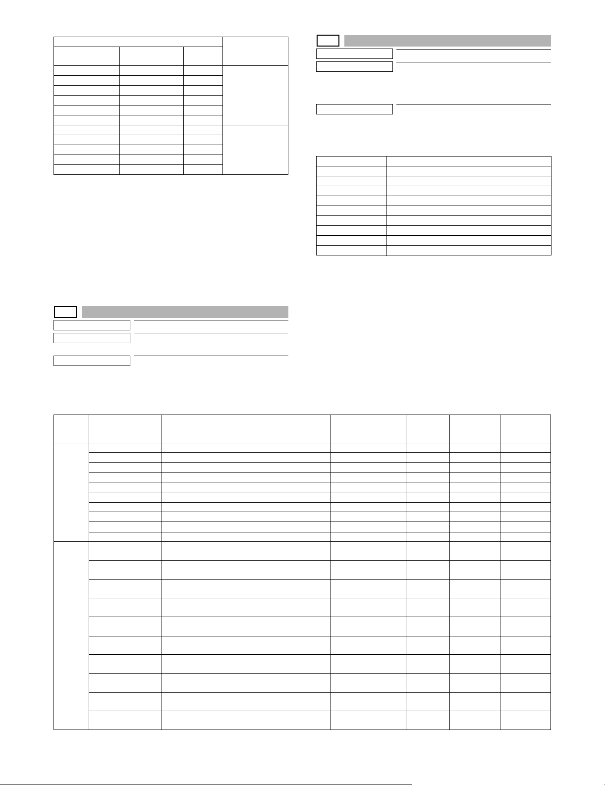
Display Item
Item name
LSU1 99/99/99 99:99:99 8 digits Serial
LSU2 99/99/99 99:99:99 8 digits
DESK1 99/99/99 99:99:99 8 digits
DESK2 99/99/99 99:99:99 8 digits
FINISHER1 99/99/99 99:99:99 8 digits
FINISHER2 99/99/99 99:99:99 8 digits
SCAN GAIN ADJ1 99/99/99 99:99:99 8 digits Scanner gain
SCAN GAIN ADJ2 99/99/99 99:99:99 8 digits
SCAN GAIN ADJ3 99/99/99 99:99:99 8 digits
SCAN GAIN ADJ4 99/99/99 99:99:99 8 digits
SCAN GAIN ADJ5 99/99/99 99:99:99 8 digits
Occurrence date
(Display)
Retry
number
Content
communication
retry number
history display
adjustment retry
history
27-13
Purpose
Function (Purpose)
Others
Used to check the history of paper transport
time between sensors. (FSS function)
Section
Operation/Procedure
Change the display with [] [] key.
27-12
Purpose
Function (Purpose)
Others
Used to check the high-density, half-tone
process control and the automatic registration adjustment error history.
(FSS Function)
Section
Operation/Procedure
The high density, the half tone, and the automatic registration
adjustment error history are displayed.
HV_ERR1 High density error history 1
HV_ERR2 High density error history 2
HV_ERR3 High density error history 3
HV_ERR4 High density error history 4
HV_ERR5 High density error history 5
H_TONE ERR1 Half tone error history 1
H_TONE ERR2 Half tone error history 2
H_TONE ERR3 Half tone error history 3
H_TONE ERR4 Half tone error history 4
H_TONE ERR5 Half tone error history 5
Item/Display Content Occurrence date
Main
FEED TIME1 History of paper transport time between sensors 1 99/99/99 99:99:99 5 digits 5 digits (ms) 5 digits (ms)
unit
FEED TIME2 History of paper transport time between sensors 2 99/99/99 99:99:99 5 digits 5 digits (ms) 5 digits (ms)
FEED TIME3 History of paper transport time between sensors 3 99/99/99 99:99:99 5 digits 5 digits (ms) 5 digits (ms)
FEED TIME4 History of paper transport time between sensors 4 99/99/99 99:99:99 5 digits 5 digits (ms) 5 digits (ms)
FEED TIME5 History of paper transport time between sensors 5 99/99/99 99:99:99 5 digits 5 digits (ms) 5 digits (ms)
FEED TIME6 History of paper transport time between sensors 6 99/99/99 99:99:99 5 digits 5 digits (ms) 5 digits (ms)
FEED TIME7 History of paper transport time between sensors 7 99/99/99 99:99:99 5 digits 5 digits (ms) 5 digits (ms)
FEED TIME8 History of paper transport time between sensors 8 99/99/99 99:99:99 5 digits 5 digits (ms) 5 digits (ms)
FEED TIME9 History of paper transport time between sensors 9 99/99/99 99:99:99 5 digits 5 digits (ms) 5 digits (ms)
FEED TIME10 History of paper transport time between sensors 10 99/99/99 99:99:99 5 digits 5 digits (ms) 5 digits (ms)
RSPF FEED TIME1(SPF) History of paper transport time between SPF
FEED TIME2(SPF) History of paper transport time between SPF
FEED TIME3(SPF) History of paper transport time between SPF
FEED TIME4(SPF) History of paper transport time between SPF
FEED TIME5(SPF) History of paper transport time between SPF
FEED TIME6(SPF) History of paper transport time between SPF
FEED TIME7(SPF) History of paper transport time between SPF
FEED TIME8(SPF) History of paper transport time between SPF
FEED TIME9(SPF) History of paper transport time between SPF
FEED TIME10(SPF) History of paper transport time between SPF
sensors 1
sensors 2
sensors 3
sensors 4
sensors 5
sensors 6
sensors 7
sensors 8
sensors 9
sensors 10
Code
between
sensors
99/99/99 99:99:99 5 digits 5 digits (ms) 5 digits (ms)
99/99/99 99:99:99 5 digits 5 digits (ms) 5 digits (ms)
99/99/99 99:99:99 5 digits 5 digits (ms) 5 digits (ms)
99/99/99 99:99:99 5 digits 5 digits (ms) 5 digits (ms)
99/99/99 99:99:99 5 digits 5 digits (ms) 5 digits (ms)
99/99/99 99:99:99 5 digits 5 digits (ms) 5 digits (ms)
99/99/99 99:99:99 5 digits 5 digits (ms) 5 digits (ms)
99/99/99 99:99:99 5 digits 5 digits (ms) 5 digits (ms)
99/99/99 99:99:99 5 digits 5 digits (ms) 5 digits (ms)
99/99/99 99:99:99 5 digits 5 digits (ms) 5 digits (ms)
Passing time
Reference
passing time
MX-B382/B402 SIMULATION 5 – 27
Page 96

27-14
Purpose
Function (Purpose)
Setting
Used to set the FSS function connection
test mode.
Section
Operation/Procedure
1) Enter the set value with 10-key.
0 Disable (Default)
1 Enable
2) Press [OK] key.
The set value in step 1) is saved.
30
30-1
Purpose
Function (Purpose)
Section
Operation/Procedure
The operating conditions of the sensors and detectors are displayed.
The sensors and the detectors which are turned ON are highlighted.
Operation test/check
Used to check the operations of the sensors and the detectors in other than the
paper feed section and the control circuits.
33
33-1
Purpose
Function (Purpose)
Section
Operation/Procedure
The operating conditions of the sensors and detectors are displayed.
The sensors and the detectors which are turned ON are highlighted.
CARD Card Yes/No detection
DATA Card number signal detection
CLOCK Reference clock signal detection
33-2
Purpose
Function (Purpose)
Section
Operation/Procedure
1) Press [EXECUTE] key.
2) Press [YES] key.
The ID (IDM) information of Felica card in the HDD is deleted.
Operation test/check
Used to check the operations of the card
reader sensor and the control circuit.
Data clear
Used to delete the ID (IDM) information of
Felica card.
PPD1 Resist pre-detection
PPD2 Resist detection
POD1 Detects the paper exit from fusing.
POD2 Main unit paper exit detection
TFD2 Paper exit tray full detection
DSW_R Right door open/close detection
DSW_F Front cover open/close detection
1TNFD Waste toner full detection
FUSET Fusing installation detection
1TUD_CL Primary transfer belt separation detection
1TUD_K Primary transfer unit initial detection
DRSET Drum detection
DRCRU_K Drum K initial detection
DVCRU_K Developer K initial detection
FUCRU Fusing initial detection
2TCCRU Secondary transfer initial detection
30-2
Purpose
Function (Purpose)
Operation test/check
Used to check the operations of the sensors and the detectors in the paper feed
section and the control circuits.
Section
Operation/Procedure
The operating conditions of the sensors and detectors are displayed.
The sensors and the detectors which are turned ON are highlighted.
CPFD1 Paper feed tray 1 paper transport detection
CLUD1 Paper feed tray 1 upper limit detection
CPED1 Paper feed tray 1 paper empty detection
CSPD1 Paper feed tray 1 paper remaining quantity detection
CSS1 Paper feed tray 1 paper size detection 1
CSS2 Paper feed tray 1 paper size detection 2
CSS3 Paper feed tray 1 paper size detection 3
MPLD Manual paper feed tray paper length detection
MPED Manual paper feed tray paper empty detection
40
40-2
Purpose
Function (Purpose)
Section
Operation/Procedure
1) Open the manual paper feed guide to the max. width (MAX).
2) Press [EXECUTE] key.
The max. width (MAX) detection level is recognized.
3) Open the manual paper feed guide to P1 width (A4R).
4) Press [EXECUTE] key.
The P1 width (A4R) detection level is recognized.
5) Open the manual paper feed guide to P2 width (A5R).
6) Press [EXECUTE] key.
The P2 width (A5R) detection level is recognized.
7) Open the manual paper feed guide to the min. width (MIN).
8) Press [EXECUTE] key.
The min. width (MIN) detection level is recognized.
When the above operation is not performed normally, "ERROR" is
displayed. When completed normally, "COMPLETE" is displayed.
MAX POSITION Manual paper feed guide maximum width position
P1 (A4R) POSITION Manual paper feed guide P1 width position (A4R)
P2 (A5R) POSITION Manual paper feed guide P2 width position (A5R)
MIN POSITION Manual paper feed guide minimum width position
Display Content
COMPLETE Adjustment completed
ERROR Adjustment error
Adjustment/Setup
Manual paper feed tray paper width sensor
adjustment.
Paper feed
MX-B382/B402 SIMULATION 5 – 28
Page 97

40-7
Purpose
Function (Purpose)
Adjustment/Setup
Used to set the adjustment value of the
manual paper feed tray paper width sensor.
Section
Paper feed
Operation/Procedure
1) Select a target item to be adjusted with [] [] buttons.
2) Enter the set value with 10-key.
3) Press [OK] key.
The set value in step 2) is saved.
Item
A MAX POSITION Manual paper feed guide maximum
width position
B P1 POSITION Manual paper feed guide P1 width
position (A4R)
C P2 POSITION Manual paper feed guide P2 width
position (A5R)
D MIN POSITION Manual paper feed guide minimum
width position
Default
value
193
187
133
84
43
43-1
Purpose
Function (Purpose)
Section
Operation/Procedure
1) Select an item to be set with [] [] keys.
2) Enter the set value with 10-key.
3) Press [OK] key.
The set value in step 2) is saved.
NOTE: The set value is the reference value, and it may differ from
the actual fusing temperature depending on the operating
conditions.
Setting
Used to set the fusing reference temperature of each operation mode.
Item/Display Content
A HL_UM READY Ready standby TH_UM set value 70 - 230 170 175 190 190
B HL_LM READY Ready standby TH_LM set value 30 - 200 120 135 130 135 130 135
C HL_US READY Ready standby TH_US set value 70 - 230 170 175 190 190
D HL_UM PLAIN PAPER BW Black-White plain paper TH_UM set value 70 - 230 170 175 190 190
E HL_LM PLAIN PAPER BW Black-White plain paper TH_LM set value 30 - 200 125 140 135 140 135 140
F HL_US PLAIN PAPER BW Black-White plain paper TH_US set value 70 - 230 170 175 190 190
G WARMUP FUMON HL_UM T Fusing motor pre-rotation start TH_UM set value 30 - 200 150
H WARMUP FUMOFF Fusing motor pre-rotation end time 0 - 255 30
I WARM UP END TIME Warm-up complete time (warm-up time (sec)) 30 - 255 83 110 83 110 83 110
J HL_UM HEAVY PAPER Heavy paper TH_UM set value 70 - 230 165
K HL_LM HEAVY PAPER Heavy paper TH_LM set value 30 - 200 140
L HL_US HEAVY PAPER Heavy paper TH_US set value 70 - 230 165
M HL_UM OHP PAPER OHP-TH_UM set value 70 - 230 150
N HL_LM OHP PAPER OHP-TH_LM set value 30 - 200 140
O HL_US OHP PAPER OHP-TH_US set value 70 - 230 150
P HL_UM ENV PAPER Envelope TH_UM set value 70 - 230 200
Q HL_LM ENV PAPER Envelope TH_LM set value 30 - 200 140
R HL_US ENV PAPER Envelope TH_US set value 70 - 230 200
S HL_UM GLOSS PAPER Glossy paper TH_UM set value 70 - 230 190
T HL_LM GLOSS PAPER Glossy paper TH_LM set value 30 - 200 140
U HL_US GLOSS PAPER Glossy paper TH_US set value 70 - 230 190
Setting
range
Group A Group B Group C
SW-A SW-B SW-A SW-B SW-A SW-B
MX-B382/B402 SIMULATION 5 – 29
Page 98

Item/Display Content
V HL_UM E-STAR Preheating TH_UM set value 30 - 200 120
W HL_US E-STAR Preheating TH_US set value 30 - 200 120
X HL_UM PRE-JOB Resetting from preheating TH_UM set value (Job Ready
temperature)
Y HL_LM E-STAR Preheating TH_LM set value 30 - 200 115
Z HL_UM WARMUP_120L Warm-up TH_UM set value (when the fusing temperature
is 120C or less)
AA HL_LM WARMUP_120L Warm-up TH_LM set value (when the fusing temperature
is 120C or less)
AB HL_US WARMUP_120L Warm-up TH_US set value (when the fusing temperature
is 120C or less)
AC LO_WARMUP_TIME Z - AB applying time (Timer from completion of Ready) 0 - 255 5
AD HL_UM WARMUP_120H Warm-up TH_UM set value (when the fusing temperature
is 120C or above)
AE HL_LM WARMUP_120H Warm-up TH_LM set value (when the fusing temperature
is 120C or above)
AF HL_US WARMUP_120H Warm-up TH_US set value (when the fusing temperature
is 120C or above)
AG HI_WARMUP_TIME AD - AF applying time (Timer from completion of Ready) 0 - 255 5
AH HI_WU_FM_ON_TMP Fusing roller rotation start TH_UM (when the fusing
temperature in warm-up is alpha C or above)
AI HI_WU_END_TIME Warm-up complete time (sec) (when the fusing
temperature in warm-up is alpha C or above)
AJ HI_WU_JOB_SET_TMP Job Ready TH_UM temperature (when the fusing
temperature in warm-up is alpha C or above)
AK HI_WARMUP_BORDER Threshold value applied to Sim43-1-AH - AJ 1 - 119 70
AL LO_WU_JOB_SET_TMP Warm-up complete time (sec) (When the fusing
temperature in warming up is alpha C or below.)
AM JOBEND_FUMON_TIME Fusing roller rotation time (sec) after completion of a job 0 - 255 2
Setting
range
30 - 200 170
70 - 230 170 175 190 190
30 - 200 120 135 130 135 130 135
70 - 230 170 175 190 190
70 - 230 165 170 190 190
30 - 200 120 135 130 135 130 135
70 - 230 165 170 190 190
30 - 200 150
0 - 255 40
70 - 230 170 175 190 190
70 - 230 170 175 190 190
Group A Group B Group C
SW-A SW-B SW-A SW-B SW-A SW-B
<Code descriptions> Destination link item (When the destination setting is changed with
TH_UM Fusing upper thermistor main
TH_LM Fusing lower thermistor main
TH_US Fusing upper thermistor sub
HL_UM Heater lamp upper main
HL_LM Heater lamp lower main
HL_US Heater lamp upper sub
SIM26-6, the set value is changed linking with the destination.)
SW-A Setting value when plain paper is selected in the system setting/device setting/fusing control setting.
SW-B Set value when heavy paper is selected in the system setting/device setting/fusing control setting.
The set value displayed in this simulation differs depending on
plain paper or heavy paper which is selected in the system setting/
Group Destination
Group A Japan China AB_B –
Group B U.S.A. Canada Inch –
Group C Europe U.K. AUS AB_A
device setting/fusing control setting.
(Example) When plain paper is selected in the system setting/
device setting/fusing control setting, the value of SW-A is displayed.
NOTE: When the destination is changed with SIM26-6 after chang-
ing this set value, the set values of the destination link
items are reset to the default.
43-4
Purpose
Function (Purpose)
Setting
Used to set the fusing temperature 2 in
each mode. (Continued from SIM 43-1.)
Section
Operation/Procedure
1) Select an item to be set with [] [] keys.
2) Enter the set value with 10-key.
3) Press [OK] key.
The set value in step 2) is saved.
NOTE: The set value is the reference value, and it may differ from
the actual fusing temperature depending on the operating
conditions.
MX-B382/B402 SIMULATION 5 – 30
Page 99

Item/Display Content
A HL_UM PLAIN PAPER BW DUP Plain paper duplex TH_UM set value 70 - 230 170 175 190 190
B HL_LM PLAIN PAPER BW DUP Plain paper duplex TH_LM set value 30 - 200 110 125 120 125 120 125
C HL_US PLAIN PAPER BW DUP Plain paper duplex TH_US set value 70 - 230 170 175 190 190
D PLAIN PAPER BW DUP APP CNT Plain paper duplex fusing temperature application
start image screen number
E HL_UM HEAVY PAPER BW DUP Heavy paper duplex TH_UM set value 70 - 230 165
F HL_LM HEAVY PAPER BW DUP Heavy paper duplex TH_LM set value 30 - 200 120
G HL_US HEAVY PAPER BW DUP Heavy paper duplex TH_US set value 70 - 230 165
H HEAVY PAPER BW DUP APP CNT Heavy paper duplex fusing temperature
application start image screen number
Setting
range
0 - 60 0
0 - 60 1
Group A Group B Group C
SW-A SW-B SW-A SW-B SW-A SW-B
<Code descriptions>
TH_UM Fusing upper thermistor main
TH_LM Fusing lower thermistor main
TH_US Fusing upper thermistor sub
HL_UM Heater lamp upper main
HL_LM Heater lamp lower main
HL_US Heater lamp upper sub
Group Destination
Group A Japan China AB_B –
Group B U.S.A. Canada Inch –
Group C Europe U.K. AUS AB_A
43-20
Purpose
Function (Purpose)
Adjustment/Setup
Used to set the environmental correction
under low temperature and low humidity (L/
L) for the fusing temperature setting (SIM
43-1) in each paper mode.
Section
Operation/Procedure
1) Select an item to be set with [] [] keys.
2) Enter the set value with 10-key.
3) Press [OK] key.
Correction value: -49 - +49, 1 Count = 1C Change
Correction value -49 -25 -5 0 5 25 49
Input value 1 25 45 50 55 75 99
The set value in step 2) is saved.
Item/Display Content
A HL_UM READY LL Ready standby TH_UM set value 1 - 99 55
B HL_LM READY LL Ready standby TH_LM set value 1 - 99 55
C HL_US READY LL Ready standby TH_US set value 1 - 99 55
D HL_UM PLAIN PAPER BW LL Plain paper TH_UM set value 1 - 99 55
E HL_LM PLAIN PAPER BW LL Plain paper TH_LM set value 1 - 99 55
F HL_US PLAIN PAPER BW LL Plain paper TH_US set value 1 - 99 55
G WARMUP FUMON HL_UM T LL Fusing motor pre-rotation start TH_UM set value 1 - 99 45
H WARMUP FUMOFF LL Fusing motor pre-rotation end time 1-99 50
I
WARMUP END TIME LL Warm-up complete time (warm-up time (sec)) 1 - 99 80
(*1)
J HL_UM HEAVY PAPER LL Heavy paper TH_UM set value 1 - 99 55
K HL_LM HEAVY PAPER LL Heavy paper TH_LM set value 1 - 99 55
L HL_US HEAVY PAPER LL Heavy paper TH_US set value 1 - 99 50
M HL_UM OHP PAPER LL OHP-TH_UM set value 1 - 99 55
N HL_LM OHP PAPER LL OHP-TH_LM set value 1 - 99 55
O HL_US OHP PAPER LL OHP-TH_US set value 1 - 99 50
P HL_UM ENV PAPER LL Envelope TH_UM set value 1 - 99 55
Q HL_LM ENV PAPER LL Envelope TH_LM set value 1 - 99 55
R HL_US ENV PAPER LL Envelope TH_US set value 1 - 99 50
S HL_UM GLOSS PAPER LL Glossy paper TH_UM set value 1 - 99 55
T HL_LM GLOSS PAPER LL Glossy paper TH_LM set value 1 - 99 55
U HL_US GLOSS PAPER LL Glossy paper TH_US set value 1 - 99 55
V HL_UM E-STAR LL Preheating TH_UM set value 1 - 99 55
W HL_US E-STAR LL Preheating TH_US set value 1 - 99 55
X HL_UM PRE-JOB LL Resetting from preheating TH_UM set value (Job Ready temperature) 1 - 99 55
Setting
range
Group AGroup BGroup
MX-B382/B402 SIMULATION 5 – 31
C
Page 100

Item/Display Content
Y HL_LM E-STAR LL Preheating TH_LM set value 1 - 99 55
Z HL_UM WARMUP_120L LL Warm-up TH_UM set value (when the fusing temperature is 120C or less) 1 - 99 55
AA HL_LM WARMUP_120L LL Warm-up TH_LM set value (when the fusing temperature is 120C or less) 1 - 99 55
AB HL_US WARMUP_120L LL Warm-up TH_US set value (when the fusing temperature is 120C or less) 1 - 99 50
AC LO_WARMUP_TIME LL Z - AB applying time (Time (sec) for shifting from the control temperature in
AD HL_UM WARMUP_120H LL Warm-up TH_UM set value (when the fusing temperature is 120C or above) 1 - 99 55
AE HL_LM WARMUP_120H LL Warm-up TH_LM set value (when the fusing temperature is 120C or above) 1 - 99 55
AF HL_US WARMUP_120H LL Warm-up TH_US set value (when the fusing temperature is 120C or above) 1 - 99 50
AG HI_WARMUP_TIME LL AD - AF applying time (Timer from completion of Ready) 1 - 99 50
AH HI_WU_FM_ON_TMP LL Fusing roller rotation start TH_UM (when the fusing temperature in warm-up
AI
HI_WU_END_TIME LL Warm-up complete time (sec) (when the fusing temperature in warm-up is
(*1)
AJ HI_WU_JOB_SET_TMP LL Job Ready TH_UM temperature (when the fusing temperature in warm-up is
AK HI_WARMUP_BORDER LL Threshold value applied to Sim43-1-AH - AJ 1 - 99 50
AL LO_WU_JOB_SET_TMP LL TH_UM temperature to enable a job during warming up (when the fusing
AM
JOBEND_FUMON_TIME LL Fusing roller rotation time (sec) after completion of a job 1 - 99 50
(*1)
warm-up to the normal control temperature)
is alpha C or above)
alpha C or above)
alpha C or above)
temperature in warming up is alpha C or below.)
Setting
range
Group AGroup BGroup
1 - 99 50
1 - 99 45
1 - 99 50
1 - 99 55
1 - 99 55
*1: 1 Count = 1sec Change
<Code descriptions>
TH_UM Fusing upper thermistor main
TH_LM Fusing lower thermistor main
TH_US Fusing upper thermistor sub
HL_UM Heater lamp upper main
HL_LM Heater lamp lower main
HL_US Heater lamp upper sub
C
Group Destination
Group A Japan China AB_B –
Group B U.S.A. Canada Inch –
Group C Europe U.K. AUS AB_A
43-21
Purpose
Function (Purpose)
Adjustment/Setup
Used to set the environment correction
under high temperature and high humidity
(H/H) for the fusing temperature setting
(SIM 43-1) in each paper mode.
Section
Operation/Procedure
1) Select an item to be set with [] [] keys.
2) Enter the set value with 10-key.
3) Press [OK] key.
Correction value: -49 - +49, 1 Count = 1C Change
Correction value -49 -25 -5 0 5 25 49
Input value 1 25 45 50 55 75 99
The set value in step 2 is saved.
Item/Display Content
A HL_UM READY HH Ready standby TH_UM set value 1 - 99 50
B HL_LM READY HH Ready standby TH_LM set value 1 - 99 50
C HL_US READY HH Ready standby TH_US set value 1 - 99 50
D HL_UM PLAIN PAPER BW HH Plain paper TH_UM set value 1 - 99 50
E HL_LM PLAIN PAPER BW HH Plain paper TH_LM set value 1 - 99 50
F HL_US PLAIN PAPER BW HH Plain paper TH_US set value 1 - 99 50
G WARMUP FUMON HL_UM T HH Fusing motor pre-rotation start TH_UM set value 1 - 99 50
H WARMUP FUMOFF HH Fusing motor pre-rotation end TH_LM set value 1 - 99 50
I
WARMUP END TIME HH Warm-up complete time (warm-up time (sec)) 1 - 99 50
(*1)
J HL_UM HEAVY PAPER HH Heavy paper TH_UM set value 1 - 99 50
K HL_LM HEAVY PAPER HH Heavy paper TH_LM set value 1 - 99 50
L HL_US HEAVY PAPER HH Heavy paper TH_US set value 1 - 99 50
Setting
range
Group AGroup BGroup
C
MX-B382/B402 SIMULATION 5 – 32
 Loading...