

Page 1
LC-30HV6U
SERVICE MANUAL
SY3M2LC30HV6U
LIQUID CRYSTAL TELEVISION
MODEL
In the interests of user-safety (Required by safety regulations in some countries) the set should be restored
to its original condition and only parts identical to those specified should be used.
OUTLINE
This model is different in the display size from the LC-37HV6U.
This service manual accordingly describes the display alone. For the entire AVC System, refer to the LC37HV4U Ser vice Manual (SY3M1LC37HV6U).
CONTENTS
Page
» IMPORTANT SERVICE SAFETY PRECA UTION .....2
» SPECIFICATIONS................................................ 5
» OPERATION MANUAL ........................................ 6
» DIMENSIONS ....................................................12
» REMOVING OF MAJOR PARTS........................13
» ADJUSTMENT PROCEDURES.........................17
» TROUBLE SHOOTING TABLE ..........................23
» CHASSIS LAYOUT.............................................28
» BLOCK DIAGRAM .............................................30
» OVERALL WIRING DIAGRAM........................... 32
» DESCRIPTION OF SCHEMATIC DIAGRAM ..... 34
» SCHEMATIC DIAGRAM..................................... 35
» PRINTED WIRING BOARD ASSEMBLIES........ 68
» PARTS LIST ....................................................... 90
» PACKING OF THE SET ...................................109
LC-30HV6U
Page
SHARP CORPORATION
This document has been published to be used for
after sales service only.
The contents are subject to change without notice.
Page 2
LC-30HV6U
1
1
IMPORTANT SERVICE SAFETY PRECAUTION
Ë
Service work should be performed only by qualified service technicians who are thoroughly familiar with all safety checks and the servicing guidelines which follow:
WARNING
» Use an AC voltmeter ha ving with 5000 ohm per v olt,
or higher, sensitivity or measure the A C v oltage drop
1. For continued safety, no modification of any circuit
should be attempted.
2. Disconnect AC power before servicing.
across the resistor.
» Connect the resistor connection to all exposed metal
parts having a return to the chassis (antenna, metal
cabinet, screw heads, knobs and control shafts,
escutcheon, etc.) and measure the AC voltage drop
across the resistor.
All checks must be repeated with the AC cord plug
connection reversed. (If necessar y, a nonpolarized
adaptor plug must be used only for the purpose of
completing these checks.)
Any reading of 0.75V rms (this corresponds to 0.5
mA rms AC.) or more is excessive and indicates a
potential shock hazard which must be corrected
A V
CAUTION: FOR CONTINUED
PROTECTION AGAINST A RISK OF
FIRE REPLACE ONLY WITH SAME
TYPE FUSE.
A VC SIDE:
F701 (2A, 250V) FUSE.
LCD SIDE: F701, F702 (4A, 250V),
F708 (500mA, 125V), F730 (2A,
125V), F703, F6551, F6552, F6553,
F6554, F6555, F6556 (2A, 250V)
before returning the monitor to the owner.
BEFORE RETURNING THE RECEIVER
(Fire & Shock Hazard)
Before returning the receiver to the user, perform
the following safety checks:
1. Inspect all lead dress to make certain that leads are
not pinched, and check that hardware is not lodged
between the chassis and other metal parts in the
receiver.
2. Inspect all protective devices such as non-metallic
control knobs, insulation materials, cabinet backs,
adjustment and compartment covers or shields,
isolation resistor-capacitor networks, mechanical
insulators, etc.
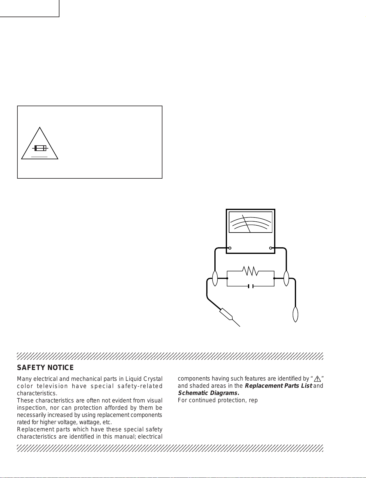
3. To be sure that no shock hazard exists, check for
leakage current in the following manner.
» Plug the AC cord directly into a 110~240 volt A C outlet.
» Using two clip leads, connect a 1.5k ohm, 10 watt
resistor paralleled by a 0.15µF capacitor in series
with all exposed metal cabinet parts and a known
TO EXPOSED
METAL PARTS
earth ground, such as electrical conduit or electrical
ground connected to an earth ground.
23456789012345678901234567890121234567890123456789012345678901212345678901234567890123456789012
DVM
AC SCALE
1.5k ohm
10W
0.15 µF
TEST PROBE
CONNECT TO
KNOWN EARTH
GROUND
SAFETY NOTICE
Many electrical and mechanical parts in Liquid Crystal
color television have special safety-related
characteristics.
These characteristics are often not evident from visual
inspection, nor can protection afforded by them be
necessarily increased by using replacement components
rated for higher voltage , wattage, etc.
Replacement parts which have these special safety
characteristics are identified in this manual; electrical
23456789012345678901234567890121234567890123456789012345678901212345678901234567890123456789012
components having such features are identified by “ å”
and shaded areas in the
Replacement Parts List
Schematic Diagrams.
For continued protection, replacement parts must be
identical to those used in the original circuit.
The use of a substitute replacement parts which do not
have the same safety characteristics as the factory
recommended replacement parts shown in this service
manual, may create shock, fire or other hazards.
2
and
Page 3
LC-30HV6U
2
2
2
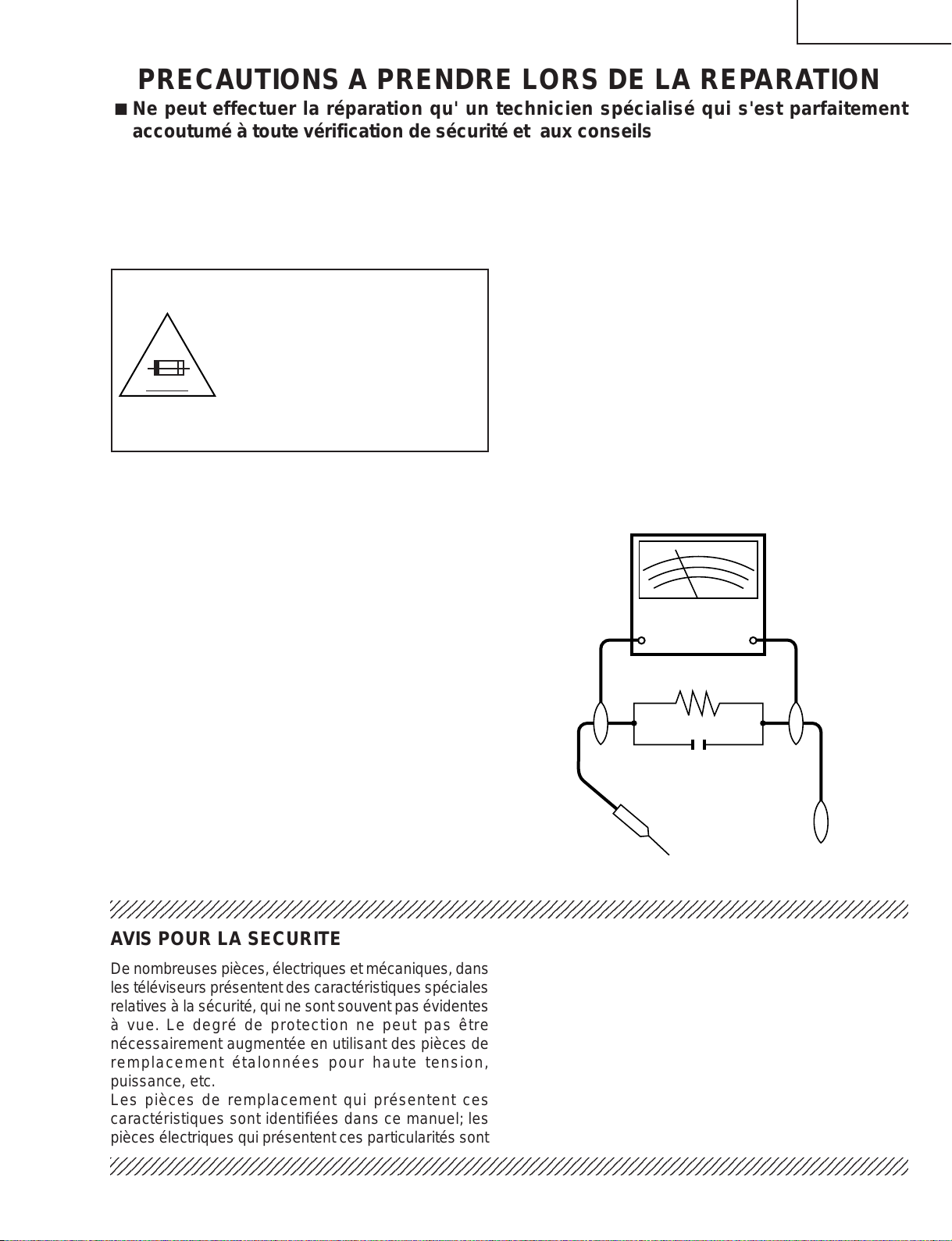
VTVM
ECHELLE CA
1.5k ohm
10W
0.15 µF
SONDE D'ESSAI
AUX PIECES
METALLIQUES
EXPOSEES
BRANCHER A UNE
TERRE CONNUE
PRECAUTIONS A PRENDRE LORS DE LA REPARATION
Ë
Ne peut effectuer la réparation qu' un technicien spécialisé qui s'est parfaitement
accoutumé à toute vérification de sécurité et aux conseils suivants.
AVERTISSEMENT
1. N'entreprendre aucune modification de tout circuit.
C'est dangereux.
2. Débrancher le récepteur avant toute réparation.
PRECAUTION: POUR LA
PROTECTION CONTINUE CONTRE
LES RISQUES D'INCENDIE,
REMPLACER LE FUSIBLE
CÔTÉ AVC:F701 (2A, 250V)
A V
CÔTÉ LCD:F701, F702 (4A, 250V),
F708 (500mA, 125V), F730 (2A,
125V), F703, F6551, F6552, F6553,
F6554, F6555, F6556 (2A, 250V)
VERIFICATIONS CONTRE L'INCEN-DIE ET
LE CHOC ELECTRIQUE
Avant de rendre le récepteur à l'utilisateur, effectuer
les vérifications suivantes.
1. Inspecter tous les faisceaux de câbles pour s'assurer
que les fils ne soient pas pincés ou qu'un outil ne soit
pas placé entre le châssis et les autres pièces
métalliques du récepteur.
2. Inspecter tous les dispositifs de protection comme les
boutons de commande non-métalliques, les isolants,
le dos du coffret, les couvercles ou blindages de réglage
et de compartiment, les réseaux de résistancecapacité, les isolateurs mécaniques, etc.
3. S'assurer qu'il n'y ait pas de danger d'électrocution en
vérifiant la fuite de courant, de la facon suiv ante:
• Brancher le cordon d'alimentation directem-ent à une
prise de courant de 110-240V. (Ne pas utiliser de
transformateur d'isolation pour cet essai).
• A l'aide de deux fils à pinces, brancher une résistance
de 1.5 kΩ 10 watts en parallèle a v ec un condensateur
de 0,15µF en série avec toutes les pièces métalliques
exposées du coffret et une terre connue comme une
conduite électrique ou une prise de terre branchée à
la terre.
• Utiliser un voltmètre CA d'une sensibilité d'au moins
5000Ω/V pour mesurer la chute de tension en travers
de la résistance.
• Toucher avec la sonde d'essai les pièces métalliques
exposées qui présentent une voie de retour au châssis
(antenne, coffret métallique, tête des vis, arbres de
commande et des boutons, écusson, etc.) et mesurer
la chute de tension CA en-travers de la résistance.
Toutes les vérifications doivent être refaites après avoir
inversé la fiche du cordon d'alimentation. (Si nécessaire,
une prise d'adpatation non polarisée peut être utilisée
dans le but de terminer ces vérifications.)
Tous les courants mesurés ne doivent pas dépasser
0.7 mA.
Dans le cas contraire, il y a une possibilité de choc
électrique qui doit être supprimée avant de rendre le
récepteur au client.
234567890123456789012345678901212345678901234567890123456789012123456789012345678901234567890121
AVIS POUR LA SECURITE
De nombreuses pièces, électriques et mécaniques, dans
les téléviseurs présentent des caractéristiques spéciales
relatives à la sécurité, qui ne sont souvent pas évidentes
à vue. Le degré de protection ne peut pas être
nécessairement augmentée en utilisant des pièces de
remplacement étalonnées pour haute tension,
puissance, etc.
Les pièces de remplacement qui présentent ces
caractéristiques sont identifiées dans ce manuel; les
pièces électriques qui présentent ces particularités sont
234567890123456789012345678901212345678901234567890123456789012123456789012345678901234567890121
234567890123456789012345678901212345678901234567890123456789012123456789012345678901234567890121
identifiées par la marque " å " et hachurées dans la
liste des pièces de remplacement et les diagrammes
schématiques.
Pour assurer la protection, ces pièces doivent être
identiques à celles utilisées dans le circuit d'origine.
L'utilisation de pièces qui n'ont pas les mêmes
caractéristiques que les pièces recommandées par
l'usine, indiquées dans ce manuel, peut provoquer des
électrocutions, incendies, radiations X ou autres
accidents.
3
Page 4
LC-30HV6U
Precautions for using lead-free solder
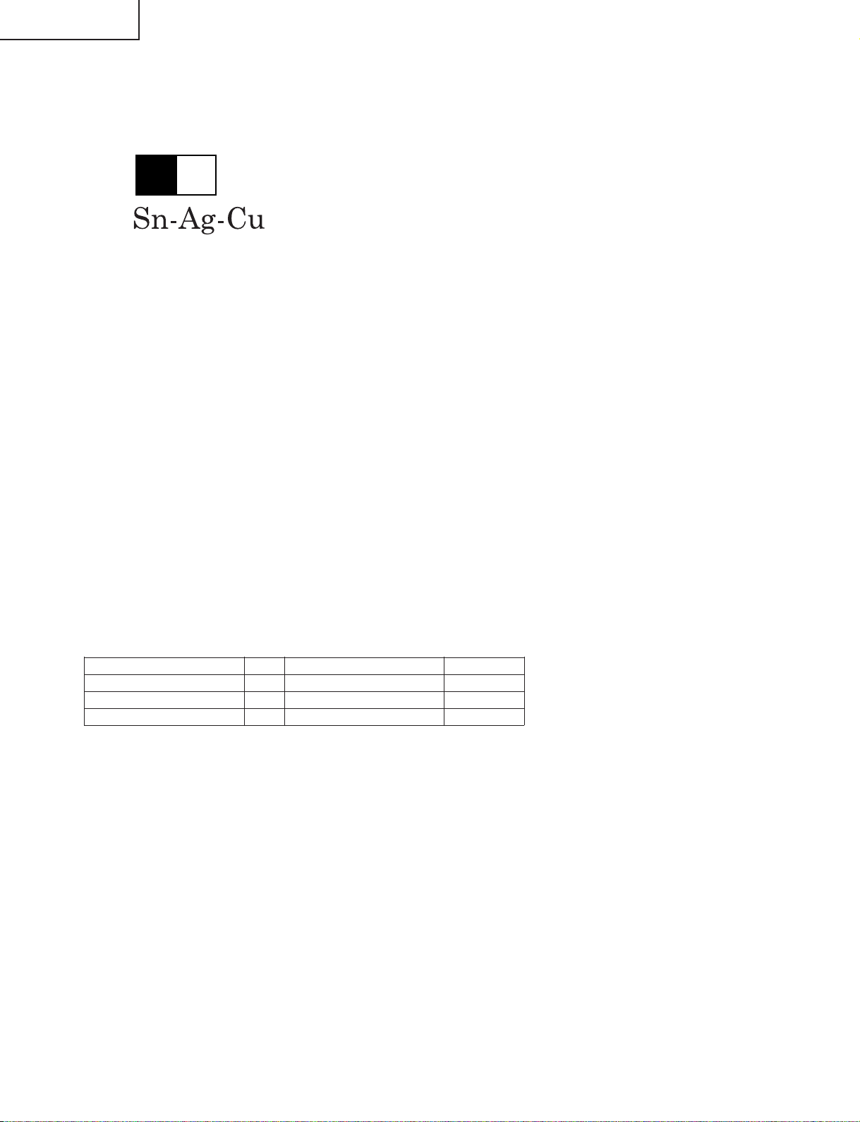
1 Employing lead-free solder
"PWBs" of this model employs lead-free solder. The LF symbol indicates lead-free solder, and is attached on the
PWBs and service manuals. The alphabetical character following LF shows the type of lead-free solder.
Example:
L Fa
Indicates lead-free solder of tin, silver and copper.
2 Using lead-free wire solder
When fixing the PWB soldered with the lead-free solder, apply lead-free wire solder. Repairing with conventional
lead wire solder may cause damage or accident due to cracks.
As the melting point of lead-free solder (Sn-Ag-Cu) is higher than the lead wire solder by 40°C, we recommend
you to use a dedicated soldering bit, if you are not familiar with how to obtain lead-free wire solder or soldering bit,
contact our service station or service branch in your area.
3 Soldering
As the melting point of lead-free solder (Sn-Ag-Cu) is about 220°C which is higher than the conventional lead
solder by 40°C, and as it has poor solder wettability, you may be apt to keep the soldering bit in contact with the
PWB for extended period of time. However, since the land may be peeled off or the maximum heat-resistance
temperature of parts may be exceeded, remov e the bit from the PWB as soon as you confirm the steady soldering
condition.
Lead-free solder contains more tin, and the end of the soldering bit may be easily corroded. Mak e sure to turn on
and off the power of the bit as required.
If a different type of solder stays on the tip of the soldering bit, it is allo y ed with lead-free solder. Clean the bit after
every use of it.
When the tip of the soldering bit is blackened during use, file it with steel wool or fine sandpaper.
Be careful when replacing parts with polarity indication on the PWB silk.
Lead-free wire solder for servicing
Part No, ★ Description Code
ZHNDAi123250E J φ0.3mm 250g(1roll) BL
ZHNDAi126500E J φ0.6mm 500g(1roll) BK
ZHNDAi12801KE J φ1.0mm 1kg(1roll) BM
4
Page 5
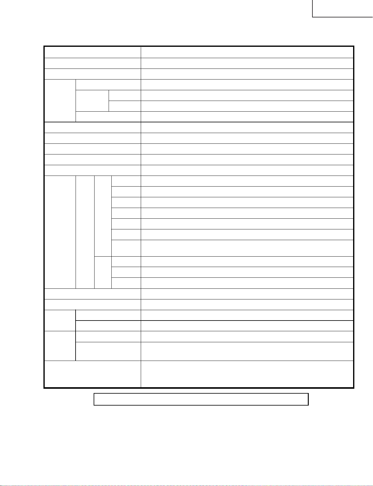
SPECIFICATIONS
Item 30" LIQUID CRYSTAL TELEVISION, Model: LC-30HV6U
TV
Function
American TV Standard NTSC System
VHF/UHF
VHF 2-13ch, UHF 14-69ch
CATV 1-125ch
Audio multiplex BTSC System
Terminals S-VIDEO in, AV in, COMPONENT in
INPUT 2
S-VIDEO in, AV in
INPUT 3
S-VIDEO in, AV in, COMPONENT in, DVI-HDTV in
ANTENNA 75 Ω Unbalance, F Type for VHF/UHF/CATV in
INPUT 4 S-VIDEO, AV in
PC
15 Pin mini D-Sub, Audio in (Ø 3.5mm jack)
OSD language English/French/Spanish
Power Requirement
AC 110-240 V, 50/60 Hz
Power
Consumption
42W (0.4W Standby with AC 120 V)
Weight
12.1 lbs./5.5 kg (w/o stand), 12.3 lbs./5.6 kg (with stand)
Accessories Operation manual (× 1), Remote control unit ( ×1), System cable ( ×1), AC cord
(× 2), “AA” size battery ( × 2), AVC sytem stand unit (× 1), Cable clamp (Large
×1, Small × 1), RF cable (× 1)
TV-standard (CCIR)
Receiving
Channel
Rear INPUT 1
Front
LCD panel 30" Advanced Super View & BLACK TFT LCD
Number of dots 2,949,120 dots (1280 × 768 × 3dots)
Brightness 430 cd/m
2
Backlight 60,000 hours (at Backlight Standard position)
Viewing angles H : 170° V : 170°
Audio amplifier 10W × 2
Speakers Ø 8cm 2pcs, Ø 2.5cm 2pcs
AVC
System
Monitor Out Audio (Variable, Fixed), S-VIDEO out, AV out
Headphones
Ø 3.5mm jack
AVC System
Display
AVC System
Display
99W (0.2W Standby with AC 120 V)
28.9 lbs./13.1 kg (Display only), 35.5 lbs./16.1 kg (with Display and speaker),
44.3 lbs./20.1 kg (with Display, speaker and stand)
DC OUTPUT DC 6.5V 7W MAX
4 Ω 10W (L/R)
EXT.
SPEAKER
Specifications are subject to change without prior notice.
LC-30HV6U
5
Page 6
LC-30HV6U
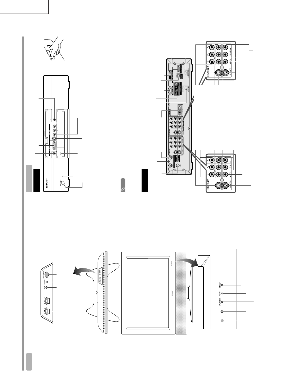
Part names
OPC indicator*
POWER indicator
MAIN POWER
button
OPC sensor
Display
POWER button
INPUT
button
VOLUME buttons
(VOL–/+)
CHANNEL buttons
(CHÙ/ù)
Remote control sensor
*OPC: Optical Picture Control
(See page 32.)
SLEEP indicator
Front view
CLEAR*
MAIN POWER button
INPUT 4 terminal (S-VIDEO)
INPUT 4 terminal (VIDEO)
PC INPUT terminal (AUDIO)
INPUT 4 terminals (AUDIO L/R)
PC INPUT terminal (ANALOG RGB)
AVC System
Rear view
INPUT 1 COMPONENT
video terminals (Y, P
B
, P
R
)
INPUT 3 COMPONENT
video terminals (Y, P
B
, P
R
)
MONITOR OUTPUT terminal
(S-VIDEO)
DISPLAY OUTPUT 1 terminal
DISPLAY
OUTPUT 2
terminal
AC INPUT
terminal
RS-232C
terminal
MONITOR OUTPUT terminals (AUDIO L/R)
Antenna (A) input terminal
Antenna (B)
input terminal
Antenna (A) output
terminal
DVI-HDTV
INPUT
terminal
INPUT 3 terminal (S-VIDEO)
INPUT 3 terminal (VIDEO)
INPUT 3 terminals (AUDIO L/R)
INPUT 1 terminal (S-VIDEO)
INPUT 1 terminal
(VIDEO)
INPUT 1 terminals
(AUDIO L/R)
INPUT 2 terminal (S-VIDEO)
INPUT 2 terminal (VIDEO)
INPUT 2 terminals
(AUDIO L/R)
How to open the door.
STANDBY/ON indicator
* If the AVC System is switched on but it does not appear to be operating corr ectly, it may need resetting. In this
case, press CLEAR, shown in the diagram, lightly with the end of a ballpoint pen or other pointed object.
This will reset the System as shown below.
• AV MODE resets to STANDARD
• TV channel returns to initial channel setting (Air:2ch, Cable:1 or 2ch)
• Twin picture resets to normal
• Audio setting initializes
• Dolby virtual resets to Off
• Image position initializes
NOTE
• Pressing CLEAR will not work if the System is in standby mode (indicator lights red).
• Pressing CLEAR will not delete channel preset or secret number. See page for clearing the secret number when you
know it. See page for initializing to the factory preset values when you forget your secr et number.
Headphone
(When connecting headphones, the sound from the
speakers is muted.)
DC OUTPUT terminal
(Terminal for expanded functionality in
the near future.)
MONITOR OUTPUT terminal
(VIDEO)
DISPLAY OUTPUT 3 terminal
EXTERNAL SPEAKER terminals
OPERATION MANUAL
6
Page 7
Part names
Remote control unit
NOTE
• When using the remote control unit, point it at the Liquid
Crystal Television.
TV
ANT-A/ B
INPUT
Virtual
TWIN
MODE
AV
POWER
MTS CC
PICTURE
SELECT
SUB TWIN CH
+
–
FREEZE
MODE
VOL CH
MUTE
MENU TV/SAT/DVD
FAVORITE CH
RECEIVER
DTV/DVD TOP
SOURCE DTV/SAT
DTV/SAT
VCR REC
ABCD
RETURN
MENU
POWER
SET/
ENTER
MENU
GUIDE
INPUT VOL
–
VOL
+
INFO
VIEW
SLEEP LEARN
EDIT/
ENT
FLASHBACK
DISPLAY
INPUT
TV VCRCBL
/SAT
/DTV
DVD
/LD
123
456
789
100
0
POWER
16
17
18
19
20
21
22
24 25
23
3
2
1
4
5
6
7
8
9
10
11
12 13
14
15
1 TV POWER: Switch the Liquid Crystal Television power
on or off.
2
Virtual: Select Virtual Dolby Surround settings.
3 AV MODE: Select an audio or video setting.
(AV mode: STANDARD, MOVIE, GAME, USER,
DYNAMIC (Fixed), DYNAMIC. PC mode:
STANDARD, USER.)
4 VIEW MODE: Select the screen size.
5 DISPLAY: Display the channel information.
6 SLEEP: Set the sleep timer.
7 FLASHBACK: Return to the previous channel or input
exter
+ –
nal mode.
8VOL/ : Set the volume.
9 MENU: Display the menu screen.
10 MENU RETURN: Return to the previous menu screen.
11 ///: Select a desired item on the screen.
12 ANT-A/B: Select between ANT-A and B to watch
broadcasts via the two tuners.
13 INPUT: Select a Liquid Crystal Television input source.
(TV, INPUT 1, INPUT 2, INPUT 3, INPUT 4, PC)
14
: When pressed all buttons on the remote control unit
will light. The lighting will turn off if no operations are
performed within about 5 seconds. This button is used
for performing operations in dark places.
15 MTS: Select the MTS/SAP.
16 CC: Display captions during closed-caption source.
17 TWIN CH buttons
TWIN PICTURE: Set the twin picture mode.
Press again to return to normal screen.
FREEZE: Set the still image. Press again to return to
normal screen.
SELECT: Select the active screen.
SUB INPUT: Select an input source of sub screen.
TWIN CH : Select the channel of sub screen.
18 0 – 9: Set the channel.
19 100 ENT: Select the three digit mode. Execute a
command of the channel.
20 CH /
/
: Select the channel.
21 MUTE: Mute the sound.
22 SET/ENTER: Execute a command.
23 FAVORITE CH
A, B, C, D: Select four preset favorite channels in four
different categories.
When
viewing via ANT-A: up to 16 channels can be
assigned in A, B, C and D.
When viewing via ANT-B: up to 16 channels can be
assigned in A, B, C and D.
With ANT-A and B combined, you can preset up to 32
favorite channels in advance.
While watching, you can toggle the selected channels
by pressing A, B, C and D.
24 LED for transmission confirmation
25 Mode switch:
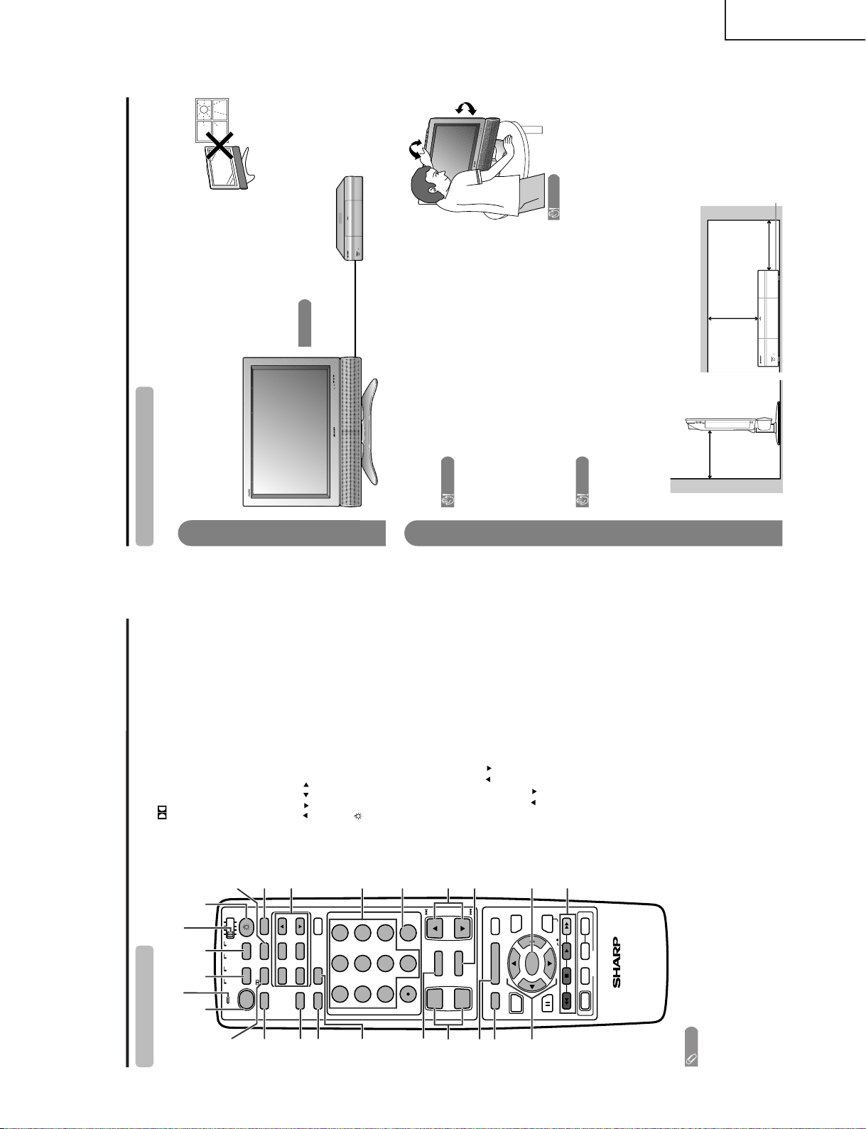
Setting the System in place
Handling the Display
CAUTION
• When using the TV with the supplied stand attached, do not
remove the speaker. Doing so may disturb the balance
leading to product damage or personal injury.
• Do not remove the stand and speaker from the Display unless
using an optional bracket to mount it.
• Keep enough space above and behind the Display.
• The Display is heavy. Move it with two or more people.
• When you move the Display, hold the portion of the Display, not
the speaker.
Handling the AVC System
CAUTION
• Do not put a VCR or other device on the AVC System.
• Keep enough space above and on the sides of the AVC System.
• Do not block the ventilation openings on the top and left side,
and the exhaust fan on the right side.
• Do not spread a thick cloth beneath the AVC System, or cover it
with one, as this can cause overheating and result in malfunction.
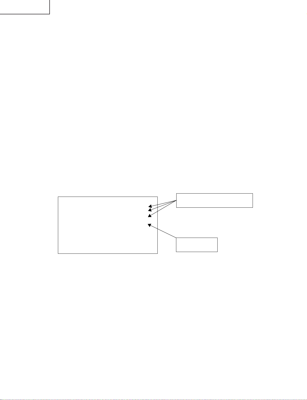
Where to place the System
“System” means the Display and AVC System. First select the location where to place the System.
Selecting the location of the System
• Select a place with no direct sunlight and good ventilation.
• The Display and the AVC System are connected by the system cable.
Keep enough space
System cable
AVC System
Display
There is an
exhaust fan on
the right side.
1
2
4 inches
(10 cm)
or more
2 inches
(5 cm) or more
2 inches
(5 cm) or
more
Preparation
If you want to keep a longer distance between the Display and AVC
System, please purchase the optional system cable AN-07SC1
(about 23 feet/7 meters).
IMPORTANT
• You cannot use external speakers when you are using the optional
system cable (AN-07SC1).
CAUTION
Adjust the screen with both
hands. Put one hand on the
Display and tilt the screen
while steadying the stand
with your other hand.
You can adjust the screen
vertically up to 4 degrees
forward or 6 degrees back-
ward, or rotate 10 degrees
horizontally.
LC-30HV6U
7
Page 8
LC-30HV6U
System cable
AVC System (rear view)
AC cord
Display (rear view)
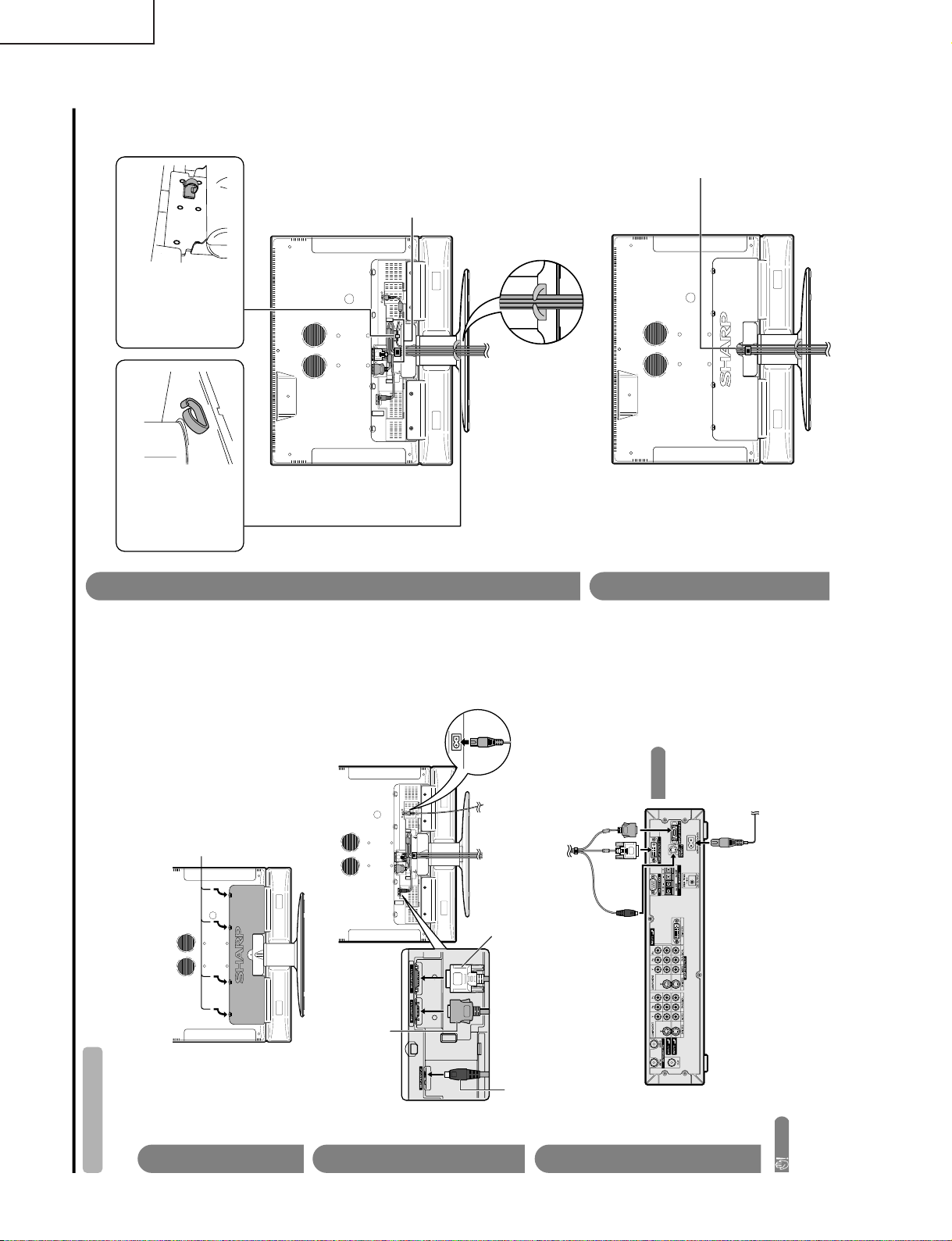
Setting the System
After putting the Display and the AVC System in place, connect the system cables and AC cords. Use the
cable clamps for bundling the cables.
Preparation
Connecting the system cable and the AC cord to the Display
1
2
3
Removing the terminal cover
Connecting the system cable and the AC cord to the AVC System
CAUTION
• TO PREVENT RISK OF ELECTRIC SHOCK, DO NOT TOUCH UN-INSULATED PARTS OF ANY CABLES WITH THE
AC CORD CONNECTED.
Press down the four
upper hooks to remove
the cover toward you.
AC cord
(GRAY)
Connect the plug firmly until
the hooks on both sides click.
(WHITE)
Connect the plug into the
terminal and secure it by
tightening the thumb screws.
(BLACK)
Connect the plug completely.
(BLACK) (WHITE) (GRAY)
You cannot use external
speakers when you are using
the optional system cable
(AN-07SC1).
IMPORTANT
System cable
4
5
Attaching the clamps and bundling the cables with the clamp
Closing the terminal cover
Cable clamp (Large)
Insert the cable
clamp in the hole
on the Display leg
as shown.
Cable clamp (Small)
Peel off the seal
on the back and
attach as shown.
Display (rear view)
Cables come
out from the
small opening.
Arrange the system
cable as shown in
the illustration.
8
Page 9
Preparation
Setting the Display on the wall
CAUTION
• Installing the Liquid Crystal Television requires special skill that should only be performed by qualified service
personnel. Customers should not attempt to do the work themselves. SHARP bears no responsibility f or improper
mounting or mounting that results in accident or injury.
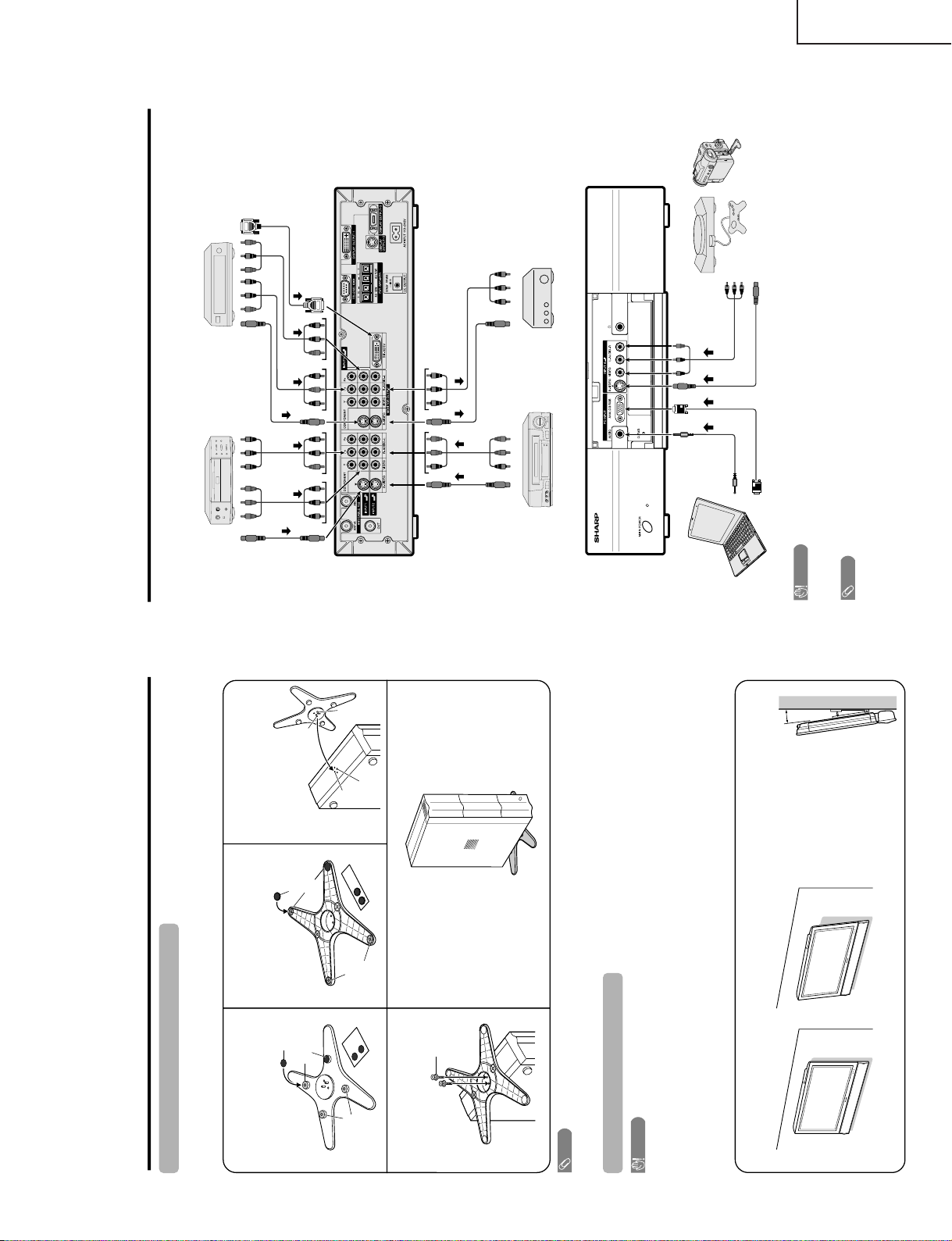
Using an optional bracket to mount the Display
• You can ask a qualified service personnel about using an optional AN-37AG1 bracket to mount the Display
to the wall.
• Carefully read the instructions that come with the bracket before beginning work.
Vertical mounting Angular mounting
Hanging on the wall
AN-37AG1 wall mount bracket. (See the bracket instructions for details.)
Setting the AVC System with the stand
1
How to install the AVC System vertically using the stand unit.
• Use the supplied stand unit for installing the AVC System vertically in an upright position.
Stick each spacer to the
stand as shown.
Peel each spacer
away from the
paper and attach
to the four bulging
areas on the stand.
2
Attach each cushion to
the stand as shown.
3
Fit the stand to the AVC
System.
Peel each cushion
away from the
paper and attach
to the four areas at
the bottom.
Insert the stand into the AVC
System, making sure that the
thick and thin bulges of the
stand align with the big and
small holes on the AVC
System.
Stand
spacer
Bulge
Stand cushion
Thin bulge
Thick
bulge
Big hole
Small
hole
4
Attach the stand using the
stand screws as shown.
Stand screw
The AVC System installed
vertically with the stand.
NOTE
• When mounting the AVC System vertically, always use the supplied stand. Be careful not to block vent holes when
standing up directly on the floor or a flat surface as this can result in equipment failure.
Attaching point
Attaching point
Bulge
5°
About setting the Display angle
• You can set the Display on the
wall up to 5 degrees forward
when the speaker is attached and
up to 20 degrees forward when
the speaker is not attached. Do
not set the angle outside those
ranges.
Using external equipment
Digital TV tuner
AVC System
(rear view)
AVC System
(front view)
AV Receiver
(Built-in Tuner Amp)VCR
DVD player
Game console/
Camcorder
PC
You can connect many types of external equipment to your System, like a DVD player, VCR, Digital TV tuner, PC,
game console and camcorder. To view external source images, select the input source from INPUT on the
remote control unit or on the Display.
CAUTION
• To protect all equipment, always turn off the AVC System before connecting to a DVD player, VCR, Digital TV tuner,
PC, game console, camcorder or other external equipment.
NOTE
• Please refer to the relevant operation manual (DVD player, PC, etc.) carefully before making connections.
S-VIDEO
S-VIDEO
S-VIDEO
AV
S-VIDEO
AV
AV
AV
Y/P
B
/P
R
Y/P
B
/P
R
PC-AUDIO
ANALOG RGB
AV
S-VIDEO
DVI
LC-30HV6U
9
Page 10
LC-30HV6U
Appendix
PC compatibility chart
Apple and Macintosh are registered trademarks
of Apple Computer, Inc.
DDC is a registered trademark of Video Electronics
Standards Association.
Power Management is a registered trademark of
Sun Microsystems, Inc.
VGA and XGA are registered trademarks of
International Business Machines Co., Inc.
PC/MAC Resolution
Horizontal Frequency
Vertical Frequency
VESA Standard
PC
31.5 kHz
37.9 kHz
31.5 kHz
37.9 kHz
31.5 kHz
37.9 kHz
37.5 kHz
43.3 kHz
31.5 kHz
35.1 kHz
37.9 kHz
48.1 kHz
46.9 kHz
53.7 kHz
48.4 kHz
56.5 kHz
60.0 kHz
68.7 kHz
45.0 kHz
48.1 kHz
64.0 kHz
34.9 kHz
49.7 kHz
60.2 kHz
640 x 400
720 x 400
VGA
640 x 480
WVGA 848 x 480
SVGA
800 x 600
1024 x 768XGA
1280 x 720
WXGA
1280 x 768
SXGA
1280 x 1024
VGA
640 x 480
MAC13"
XGA
1024 x 768
MAC19"
SVGA
832 x 624
MAC16"
60 Hz
85 Hz
60 Hz
85 Hz
60 Hz
72 Hz
75 Hz
85 Hz
60 Hz
56 Hz
60 Hz
72 Hz
75 Hz
85 Hz
60 Hz
70 Hz
75 Hz
85 Hz
60 Hz
60 Hz
60 Hz
67 Hz
75 Hz
75 Hz
O
O
O
O
O
O
O
O
O
O
O
O
O
O
O
O
RS-232C port specifications
Return codeCommand 4-digits Parameter 4-digits
PC Control of the System
• When a program is set, the Display can be controlled from the PC using the RS-232C terminal.
The input signal (PC/AV) can be selected, the volume can be adjusted and various other adjustments and
settings can be made, enabling automatic programmed playing.
•
Attach an RS-232C cable cross-type (commercially available) to the supplied Din/D-Sub RS-232C for the
connections.
NOTE
• This operation system should be used by a person who is accustomed to using computers.
Communication conditions
Set the RS-232C communications settings on the PC to match the display
’
s communications conditions.
The Display’s communications settings are as follows:
Baud rate:
Parity bit:
Data length:
Stop bit:
Flow control:
9,600 bps
8 bits
None
1 bit
None
Command format
Communication procedure
Send the control commands from the PC via the RS-232C connector.
The display operates according to the received command and sends a response message to the PC.
Do not send multiple commands at the same time. Wait until the PC receives the OK response before sending
the next command.
Eight ASCII codes CR+
Command 4-digits:Command. The text of four characters.
Parameter 4-digits:Parameter 0 – 9, x, blank, ?
Parameter
Input the parameter values, aligning left, and fill with blank(s) for the remainder. (Be sure that 4 values are input for the
parameter.)
When the input parameter is not within an adjustable range,
“ERR” r
eturns. (Refer to “Response code format”.)
No problem to input any numerical value for
“x” on the table.
When “?” is input for some commands, the present setting value responds.
C1 C2 C3 C4 P1 P2 P3 P4
0055
100
30
0009
0
–
????
?
10
Page 11
LC-30HV6U
Command table
• About the command except being indicated here, it is outside the guarantee range of operation.
CONTROL ITEM COMMAND
PARAMETER
CONTROL CONTENTS
POWER SETTING It shifts to standby.
It input-switches by the toggle. (It is the same as an input change key)
It input-switches to TV. (A channel remains as it is. (Last memory))
It input-switches to INPUT1~INPUT4.
It input-switches to PC.
An input change is also included.
Although it can choose now, it is toggle operation in inside.
Although it can choose now, it is toggle operation in inside.
(Toggle)
Input terminal number (1
–4
)
AUTO
AV-Y/C
COMPONENT
AUTO
AV-Y/C
COMPONENT
DVI
(Toggle)
STANDARD
MOVIE
USER
GAME
DYNAMIC (Fixed)
DYNAMIC
Volume (0–60)
AV mode. (±10)
PC mode. (0–180)
AV mode. (±20)
PC mode. (0–99)
Only PC mode. (0
–180)
Only PC mode. (0
–40)
(Toggle) [AV]
An input change is included if it is not TV display.
In Air, 2–69ch is effective.
In Cable, 1–125ch is effective.
If it is not TV display, it will input-switch to TV.
If it is not TV display, it will input-switch to TV.
Change toggle operation of tuner A/B.
Toggle operation of a closed caption.
(Toggle)
Side Bar [AV]
S.Stretch [AV]
Zoom [AV]
Stretch [AV]
Normal [PC]
Stretch [PC]
Dot by Dot [PC]
Zoom [PC]
On
Off
One screen
Twin screens
The channel number of TV
The channel number of TV +1
The channel number of TV –1
(Toggle)
(Toggle)
OFF
CC1
CC2
T1
T2
(1–125)
AUTO
POWR
ITGD
ITVD
IAVD
IPCD
INP1
INP3
INPUT SELECTION A TOGGLE
INPUT SELECTION B
AV MODE SELECTION
VOLUME
POSITION
VIEWMODE
Dolby Virtual
TWIN PICTURE
CHANNEL
ANT-A/B
CC
DIRECT
CH UP
CH DOWN
CHANNEL
H-POSITIONH-POSITION
V-POSITION
CLOCK
PHASE
INPUT 1
INPUT 3
AVMD
VOLM
HPOS
VPOS
CLCK
PHSE
ACDV
TWI N
DCCH
CHUP
CHDW
ANTS
CLCP
WIDE
0
x
0
*
x
0
0
1
2
3
1
2
0
*
*
*
*
*
0
0
*
x
x
x
0
1
2
3
4
5
1
1
2
0
1
2
3
4
5
6
7
8
*
*
1
2
3
4
5
6
*
_
_
_
_
_
_
_
_
_
_
_
_
_
_
_
_
_
_
_
_
_
_
_
*
*
*
*
*
*
*
_
_
_
_
_
_
_
_
_
_
_
_
_
_
_
_
_
_
_
*
_
_
_
_
_
_
_
_
_
_
_
_
_
_
_
_
_
_
_
_
_
_
_
*
*
*
*
*
*
_
_
_
_
_
_
_
_
_
_
_
_
_
_
_
_
_
_
_
_
_
_
_
_
_
_
_
_
_
_
_
_
_
_
_
_
_
_
_
_
_
_
_
_
_
_
_
_
_
_
_
_
_
_
_
_
_
_
_
_
_
_
_
_
_
_
_
_
_
_
TV
INPUT1-4
PC
Appendix
NOTE
• If an underbar (_) appears in the parameter column, enter a space.
• If an asterisk (*) appears, enter a value in the range indicated in brackets under CONTROL CONTENTS.
• As long as that from which the parameter ( ) in the table is a numerical value, it may write anything.
Return code (0DH)
Response code format
Normal response
Problem response (communication error or incorrect command)
Return code (0DH)
OK
ERR
×
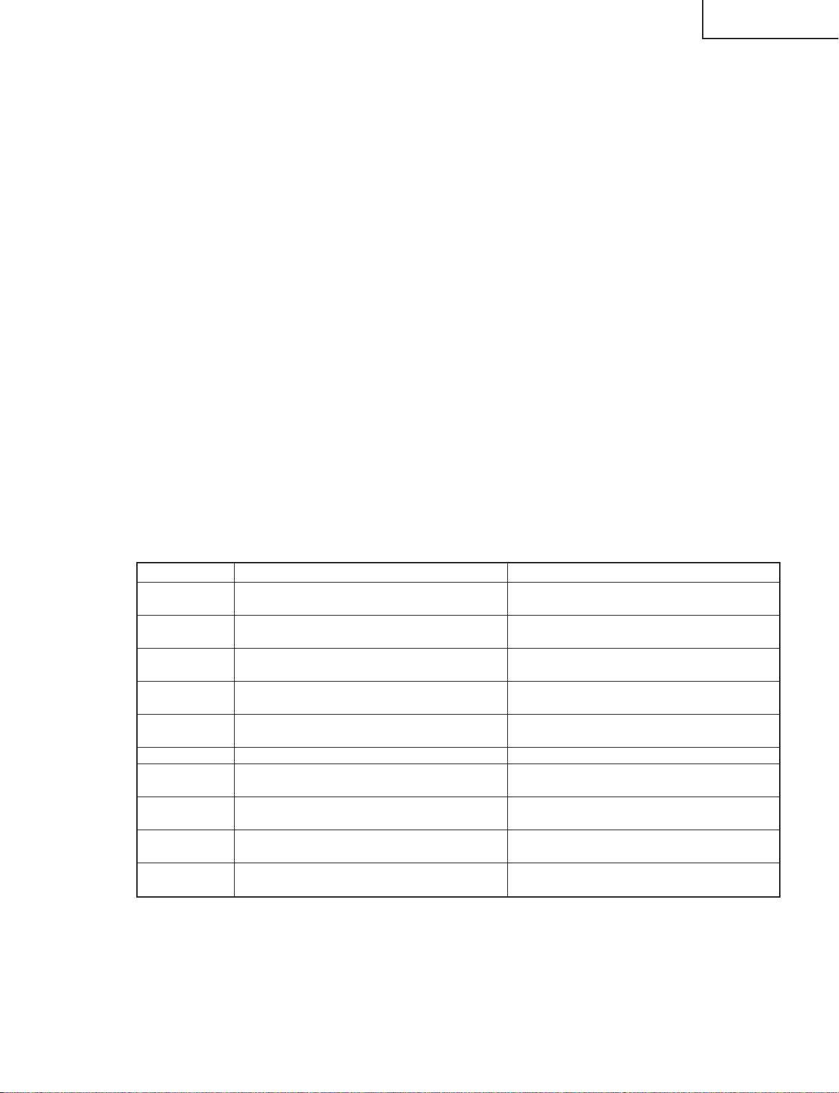
Basic adjustment settings
AV input mode menu items
List of AV menu items to help you with
operations
OPC
Backlight
Contrast
Brightness
Color
Tint
Sharpness
Advanced
C.M.S.
Color Temp.
Black
3D-Y/C
Monochrome
Film Mode
I/P Setting
Picture
No Signal Off
No Operation Off
EZ Setup
CH Setup
Speaker
Input Signal
Parental CTRL
Position
Stretch Mode
Picture Flip
Language
Treble
Bass
Balance
Dolby Virtual
Audio Only
Input Select
DNR
Audio Out
Quick Shoot
Audio
Power Control
Setup
Option
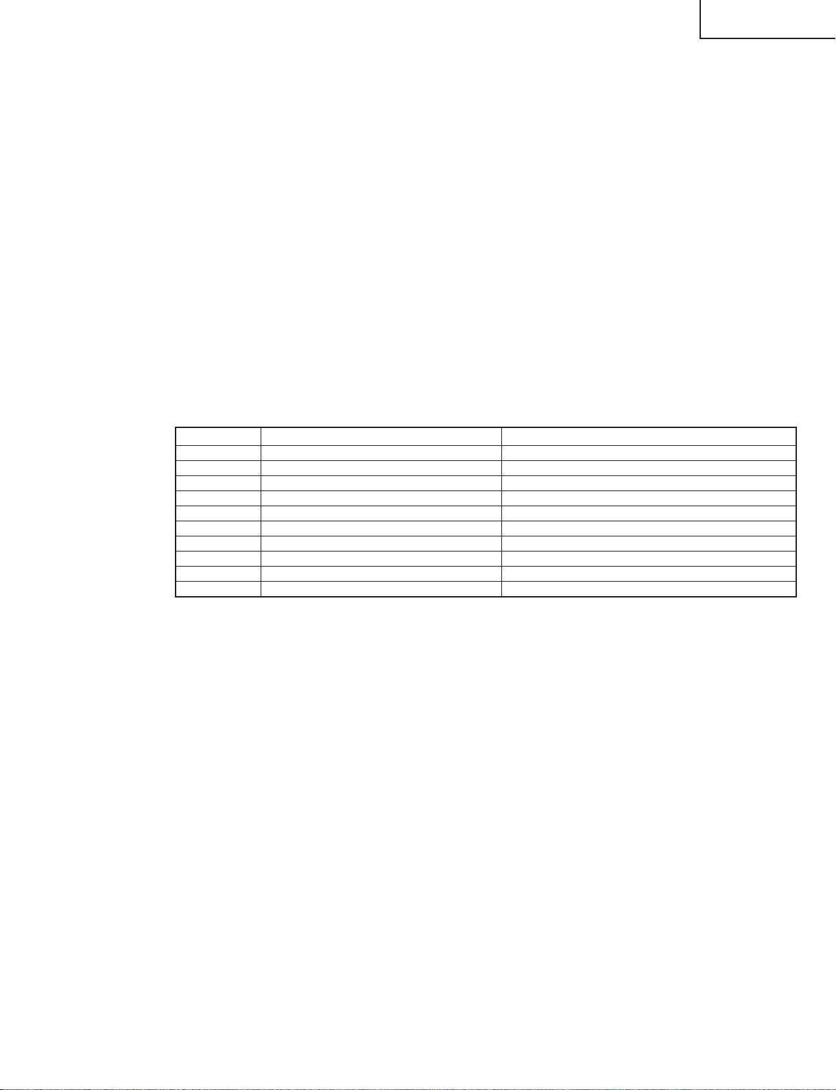
PC input mode menu items
List of PC menu items to help you with
operations
OPC
Backlight
Contrast
Brightness
Red
Green
Blue
C.M.S.
Picture
Power Management
Speaker
Input Signal
Auto Sync.
Fine Sync.
Picture Flip
Language
Audio
Power Control
Setup
Treble
Bass
Balance
Dolby Virtual
Option
Audio Only
Audio Out
Quick Shoot
11
Page 12
LC-30HV6U
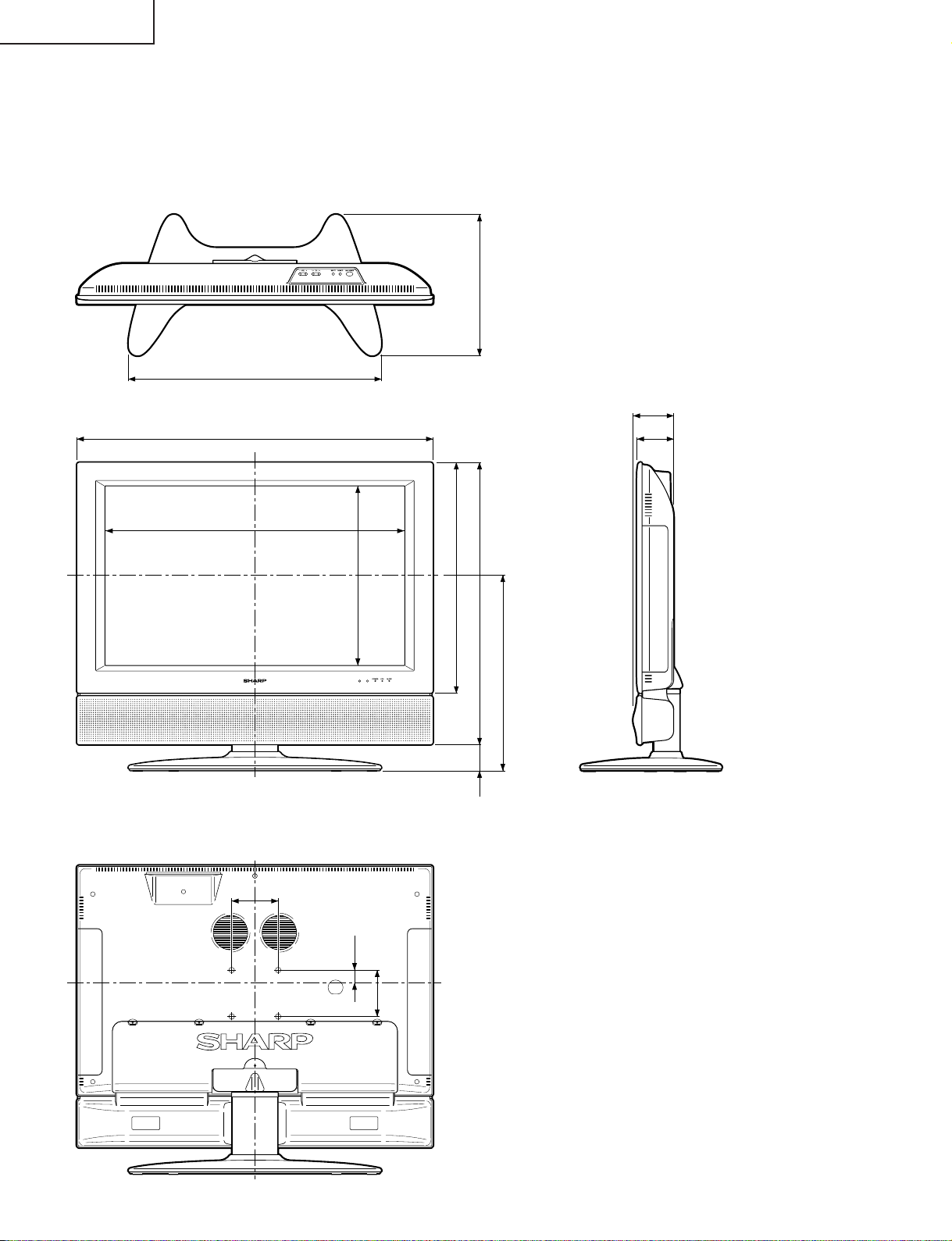
2129/64(545)
305/32(766)
DIMENSIONS
12(305)
315/32(88)
7
/64(79)
3
Unit: inch/(mm)
25
23
/64(644.2)
3
15
/16(100)
(385.8)
16
/
3
15
(18.5)
32
/
23
(497)
(608)
16
/
16
9
/
15
19
23
(422)
64
/
39
16
32
/
9
(58)
2
/
15
(100)
3
12
Page 13
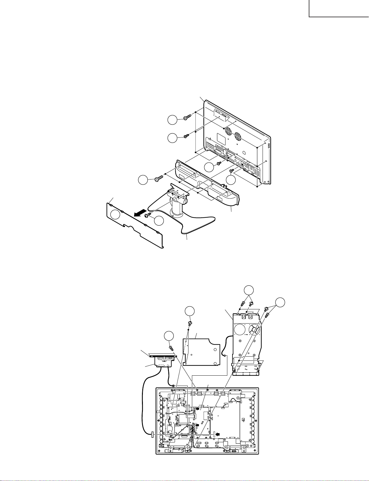
REMOVING OF MAJOR PARTS
Ë Ë
Ë Display
Ë Ë
1. Take off bottom terminal cover.
2. Take off the table stand by removing 6 screws.
3. Take off the speaker by removing 4 screws and disconnecting speaker terminals.
4. Take off the cabinet B by removing 18 screws and releasing the cabinet A’s 6 hooks.
Cabinet B
4
4
4
LC-30HV6U
3
Terminal Cover
1
4
Speaker
2
Table Stand
5. Take off the center angle by removing 8 screws and disconnecting 1 lead wire from the fan.
6. Take off the top cover assembly by removing 2 screws and detaching the connector.
7. Take off the insulating spacer by removing 2 screws.
5
Center Angle
5
7
6
Shield Sheet
Top Cover Ass'y
KEY PWB
P131 P130
MAIN PWB
P2103
P2002
POWER PWB
CN712
13
Page 14
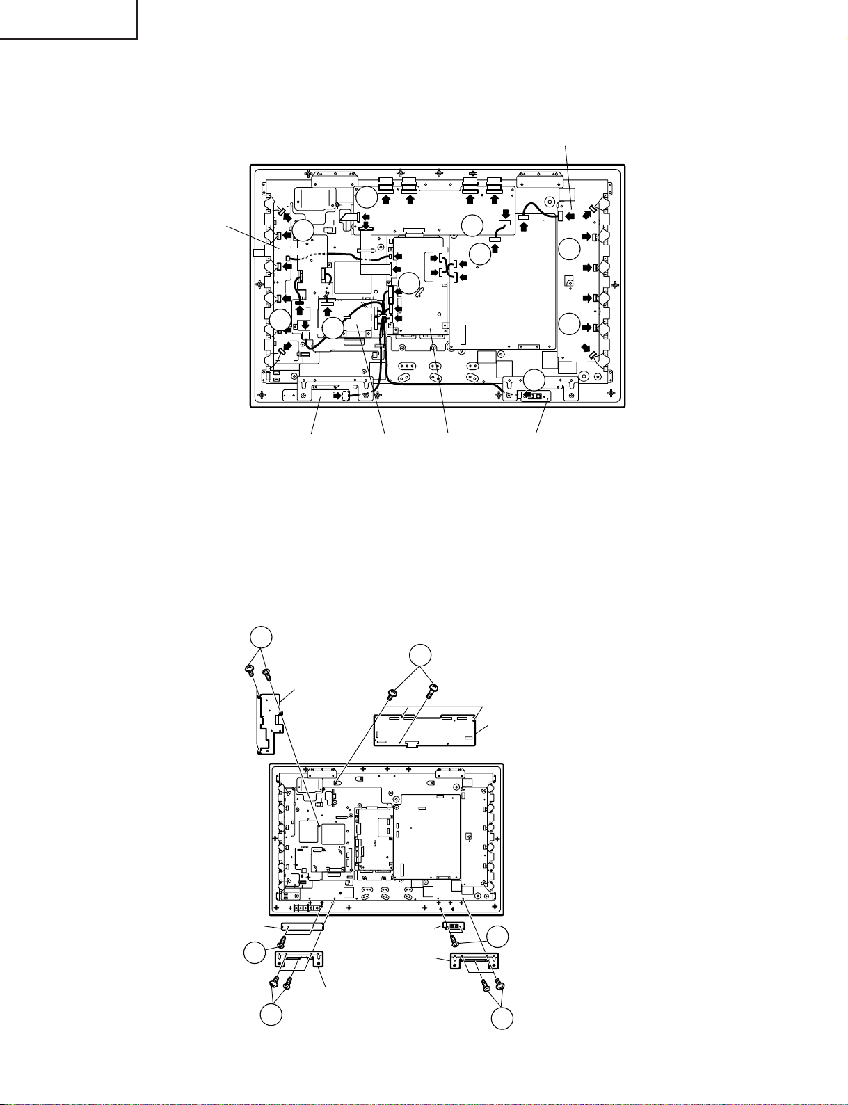
LC-30HV6U
8. Detach each connector
(8 from the LCD Control PWB, 7 from the Main PWB, 4 from the Power PWB, 7 from the Inverter PWB, 1 from the
speaker-Jack PWB, 1 from the R/C, LED PWB, 6 from the Inverter-GND PWB, 3 from the Audio PWB.)
INVERTER PWB
8
SC4601
SC4603
SC4601
LCD CONTROL PWB
SC4605
P2106
SC2001
8
P3801
P2004
P2004
P2104
P3803
P3804
8
P101
INVERTER-GND
PWB
P8601
P8602
P8603
P8604
8
P8605
8
P8607
P3903
P3204
P8606
R/C, LED Unit AUDIO PWB MAIN PWB
9. Take off the 1-Bit Amp. PWB chassis by removing 3 screws.
10.Take off the LCD Control PWB by removing 4 screws.
11.Take off the Speaker retaining angle by 3 screws.
12.Take off the R/C, LED PWB by 2 screws.
13.Take off the Speaker-Jack PWB by 2 screws.
14.Take off the Speaker retaining angle by 3 screws.
SC4604
8
P2101
CN722
P2102
CN724
POWER PWB
SC4602
P7701
CN209
CN723
8
8
P201
SPEAKER-JACK PWB
P6564
P6551
P6553
8
P6555
P6558
8
P6560
P6562
R/C, LED PWB
12
9
1-Bit Amp. PWB
Chassis
SPEAKER-JACK
PWB
Speaker Retaining Angle
11
10
LCD CONTROL PWB
13
Speake Retainig
Angle
14
14
Page 15
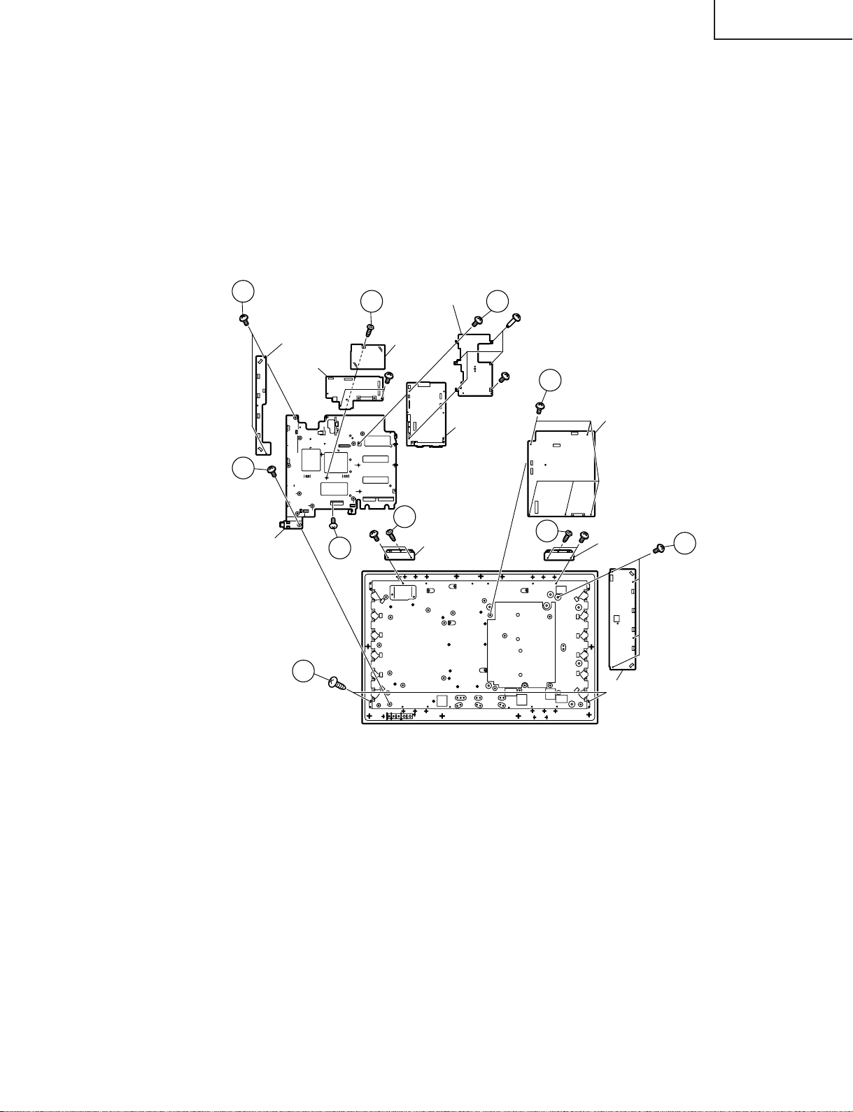
15.Take off the Inverter PWB by removing 4 screws.
16.Take off the Power PWB by removing 5 screws. Remove insulation sheet.
17.Take off the Main PWB by removing 6 screws.
18.Take off the Audio PWB by removing 3 screws
19.take off the Inverter-GND PWB by removing 2 screw.
20.Take off the chassis frame by removing 1 screw.
21.Take off the reinforcement angles by removing 3 screws from each angle.
22.Take off the LCD panel unit by removing 2 screws.
LC-30HV6U
19
INVERTER-GND
PWB
AUDIO PWB
20
Chassis Frame
22
18 17
Audio PWB
Shield
21
Reinforcement
18
Angle
Shield
MAIN PWB
16
21
POWER PWB
Reinforcement
Angle
INVERTER PWB
15
15
Page 16
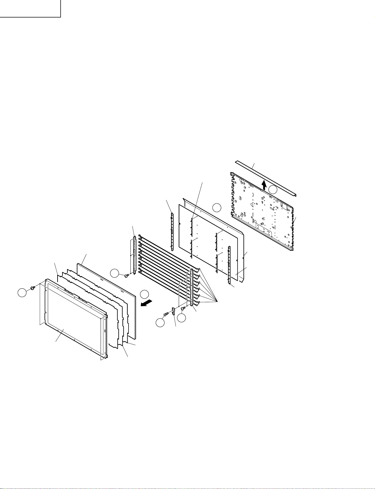
LC-30HV6U
• Precautions in handling the LCD panel
1. Handle the liquid crystal panel in a clean room (Humidity: 50% or more).
2. Be sure to wear an earth wristband.
3. Be careful not to drop and shock the liquid crystal panel.
4. Use an ionizer (within 30 cm).
23.Remove the four lock screws from the LCD panel.
24.Peel off the conductive sheet.
25.Detach the deflection sheet, prism sheet, diffusion sheet and diffusion panel.
26.Remove the two lock screws from ITO earth spring.
27.Remove the three lock scre ws from each of the top and bottom lamp holders , and detach the top and bottom lamp
holders.
28.Detach the lamp assembly from the lamp clip.
Condutive Sheet
Lamp Clip (4 pcs.)
(LHLDZA085WJZZ)
Deflection Sheet
(PSHEPA108WJZZ)
23
30" LCD Panel Unit
(RLCDTA026WJZZ)
Lamp Fixing Holder (Top)
(LHLDZA083WJKZ)
Deflection Panel
(PCOVUA017WJZZ)
27
Lamp Fixing Holder (Bottom)
(LHLDZA084WJKZ)
25
26
ITO Earth Spring
(MSPRP1220CEFW)
Diffusion Sheet
(PSHEPA110WJZZ)
Prism Sheet
(PSHEPA179WJZZ)
Lamp Fixing Holder (Top)
27
(LHLDZA083WJKZ)
24
28
Back Shield Ass'y
Reflection Sheet
Reflection Sheet
Lamp Fixing Holder (Bottom)
(LHLDZA084WJKZ)
Lamp
(KLMP-A021WJZZ)
16
Page 17
LC-30HV6U
ADJUSTMENT PROCEDURES
The adjustment values are set to the optimum conditions at the factory before shipping. If a value should become
improper or an adjustment is required due to part replacement, make an adjustment according to the following
procedure.
1. Preparation
Note that the unit should be replaced when the receiver IC (IC2206), CONFIG ROM (IC2202) or microprocessor
(IC2004) is replaced.
Applicable unit: DKEYHC094FE51
2. Adjusting procedure
• VLS BIAS (15V) voltage adjustment
• Entering the adjustment process mode → COM BIAS adjustment → Background adjustment
3. How to enter the adjustment process mode
(1) When the AVC center is not connected
• Turn OFF the monitor main power. Turning ON the monitor main power while pressing the "INPUT" key
and "VOL (–)" ke y on the top face of the monitor main body together will establish the "Monitor Process"
mode.
(2) When the AVC center is connected
• Turn OFF the monitor main power. Turning ON the monitor main power while pressing the "CH (Ù)" key
and "VOL (+)" key on the top face of the monitor main body together will establish "Monitor Process"
mode.
In each case of (1) and (2), "<K>" is displayed in the upper left portion of the screen.
Then, pressing any key will bring you to the first page of the "Monitor Adjustment" mode.
~ To exit the adjustment process mode, turn OFF the main power.
4. Adjustment process mode key operation table
Key
Cursor UP
Cursor DOWN
Cursor RIGHT
Cursor LEFT
ENTER
INPUT
CH (ù)
CH (Ù)
VOL (+)
VOL (–)
Function 1 (when on the left side of a page)
Moving up by one item or moving to the
previous page (when at the top)
Moving down by one item or moving to the next
page (when at the bottom)
Moving to the right by one item or moving to
another page (in the case of the initial page)
Moving to the left by one item or moving to
another page (in the case of the initial page)
Test pattern off
Moving to the next page
Moving down by one item or moving to the next
page (when at the bottom)
Moving down by one item or moving to the next
page (when at the bottom)
Moving to the right by one item or moving to
another page (in the case of the initial page)
Moving to the left by one item or moving to
another page (in the case of the initial page)
Function 2 (when changing a numeric value)
Incrementing the adjustment value by one or
executing the item (in the case of W or R items)
Decrementing the adjustment value by one or
executing the item (in the case of W or R items)
Moving to the right by one item
Moving to the left by one item
Executing the item (in the case of W or R
items)
Moving to the next page
Incrementing the adjustment value by one or
executing the item (in the case of W or R items)
Decrementing the adjustment value by one or
executing the item (in the case of W or R items)
Moving to the right by one item
Moving to the left by one item
17
Page 18

LC-30HV6U
5. Adjustment
5-1.VLS BIAS (13V) voltage adjustment (R4231)
5-2.COM BIAS adjustment
5-3.Background adjustment
Connect a digital volt meter to TL4122 (or C4180+) on the LCD Control PWB and make a adjustment with
the R4231 so that the voltage becomes 13.00V±0.05V.
Shift to the "COM BIAS" item with the cursor UP/DOWN key and select a numeric value with the cursor
RIGHT/LEFT key.
Changing the numeric value with the cursor UP/DOWN key will make appear the test patter n. Make an
adjustment so that the flicker near the center of the screen is minimized.
Start up the set with the AVC System connected and adjust the background of the monitor.
• Procedure
-1) Display the adjustment screen (200-level gray scale on High side, 48-level gray scale on Low side).
-2) Adjust "R OFFSET", "G OFFSET" and "B OFFSET" so that the 200-level gr ay scale pattern becomes
normative.
Adjust the chromaticity of the High pattern (in the left portion of the screen) so that x = 0.290 and y =
0.299.
-3) Adjust "R GAMMA", "G GAMMA" and "B GAMMA" so that the 48-level gray scale pattern becomes
normative.
Adjust the chromaticity of the Low pattern (in the right portion of the screen) so that x = 0.276 and y
= 0.278.
The above-mentioned adjustments can be made according to the following procedure.
18
Page 19
LC-30HV6U
(1) Adjusting method using RS-232C
• Get a personal computer with a COM port (RS-232C) equipped with WINDOWS 95/98/me/2000/xp and
a RS-232C crossing cable
• Start up the set with the RS-232C cable connected.
• Start up the terminal software.
(Freeware products available on the Internet can be used.)
• Make setting as shown below.
Baud rate : 9600
Data : 8 bits
Parity : None
Stop : 1 bit
Flow control : None
• If the above setting is made correctly, pressing the "SET/ENTER" key on the PC will make "ERR" appear
on the terminal software.
• In this state, entering a command shown in the table bellow and pressing the "SET/ENTER" ke y will allo w
you to make an adjustment.
If "OK" is displayed on the terminal software after the "SET/ENTER" key is pressed, the command has
been entered successfully.
If "ERR" is displayed, enter the command again.
RS232C command table
Command
MSET1001
MOFR~~~~
MOFG~~~~
MOFB~~~~
MGAR~~~~
MGAG~~~~
MGAB~~~~
MINF0000
MINF0001
MINF0002
Function
Used to start the background adjustment.
Used to adjust the value of R OFFSET.
Used to adjust the value of G OFFSET.
Used to adjust the value of B OFFSET.
Used to adjust the value of R GAMMA.
Used to adjust the value of G GAMMA.
Used to adjust the value of B GAMMA.
Used to display the R GAMMA table.
Used to display the B GAMMA table.
Used to display the G GAMMA table.
Remarks
The adjustment ends with a numeric value other than 1001.
Range: 0000 to 0512 (Initial value: 0255)
Range: 0000 to 0512 (Initial value: 0255)
Range: 0000 to 0512 (Initial value: 0255)
Range: 0000 to 0255 (Initial value: 0100)
Range: 0000 to 0255 (Initial value: 0100)
Range: 0000 to 0255 (Initial value: 0100)
19
Page 20
LC-30HV6U
Lamp error detection
1. Feature description
This liquid-crystal color TV incorporates a lamp error detection feature (lamp error detection) that automatically
turns OFF the power for safety under abnormal lamp or lamp circuit conditions.
If anything is wrong with the lamp or lamp circuit or the lamp error detection feature is activated for some
reason, the following will result.
1 The power of TV main body is turned OFF about 13 seconds after it is turned ON. (The power LED on
2 If 1 occurs five times consecutively, it becomes impossible to turn ON the power. (The power LED
2. Measures
2-1.Checking with lamp error detection OFF
Disconnect the cable connected to the AVC System Turn OFF the monitor main power. Turning ON the
monitor main power while pressing the "INPUT" key and "VOL (–)" key together will establish the "Monitor
Process" mode ("<K>" is displayed).
Then, pressing any key will bring you to the first page of the "Monitor Process" mode.
This allow you to check the lamp and lamp circuit for abnormal conditions.
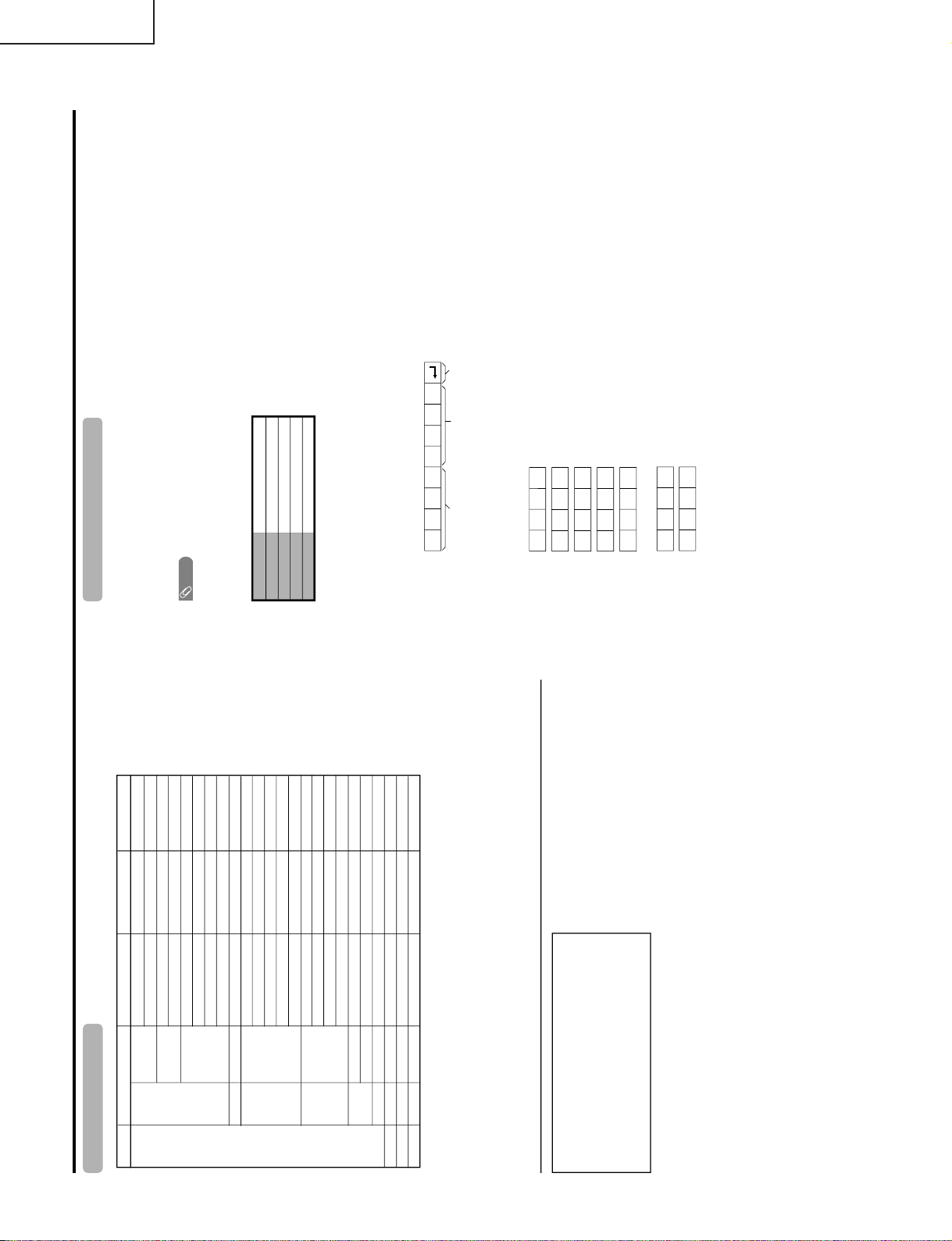
Check that "L ERR RESET" on the fourth line of the first page of the "Monitor Process" mode is 1 or more.
If it is 1 or more, a lamp error has been detected.
2-2.Reset of lamp error count
After checking the lamp and lamp circuit for abnormal conditions, reset the lamp error count. Move the
arrow to "L ERR RESET" on the fourth line of the first page of the "Monitor Process" mode with the cursor
UP/DOWN ke y and select the numeric value of "L ERR RESET" with the cursor RIGHT/LEFT key. In this
state, press the cursor UP/DOWN key to reset it to "0".
the front of the TV turns red from green and keeps blinking in red (ON for 250ms and OFF for 1sec).)
keeps blinking in red (ON for 250ms and OFF for 1sec).)
First page of monitor process mode
SERVICE
NOTHING
COMBIAS
NOTHING
→L ERR RESET
LCD
PATTERN
SOUND AND FAN
OTHER
VER M1.~~ CEEP4
Then perform operation checking and check that the lamp error detection feature is not activated.
30AD1
076
077
064
5
Values specific to each monitor
Resetting to "0"
20
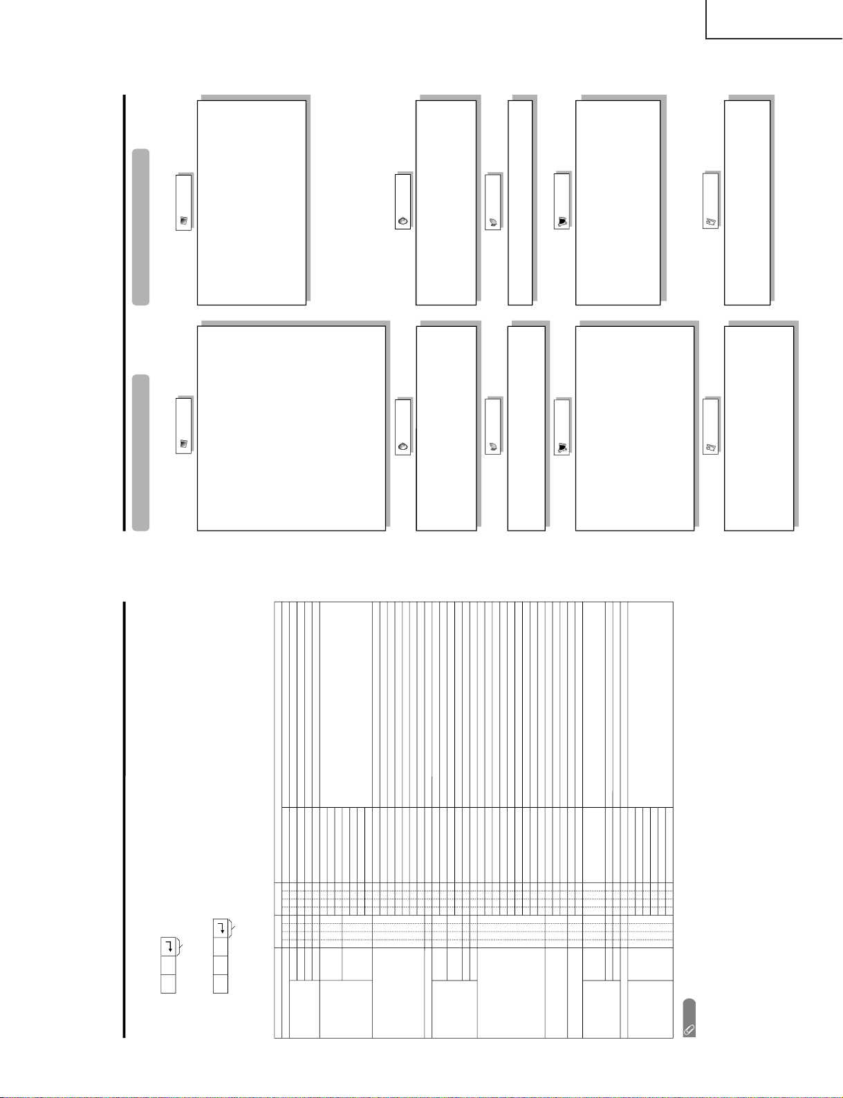
Page 21
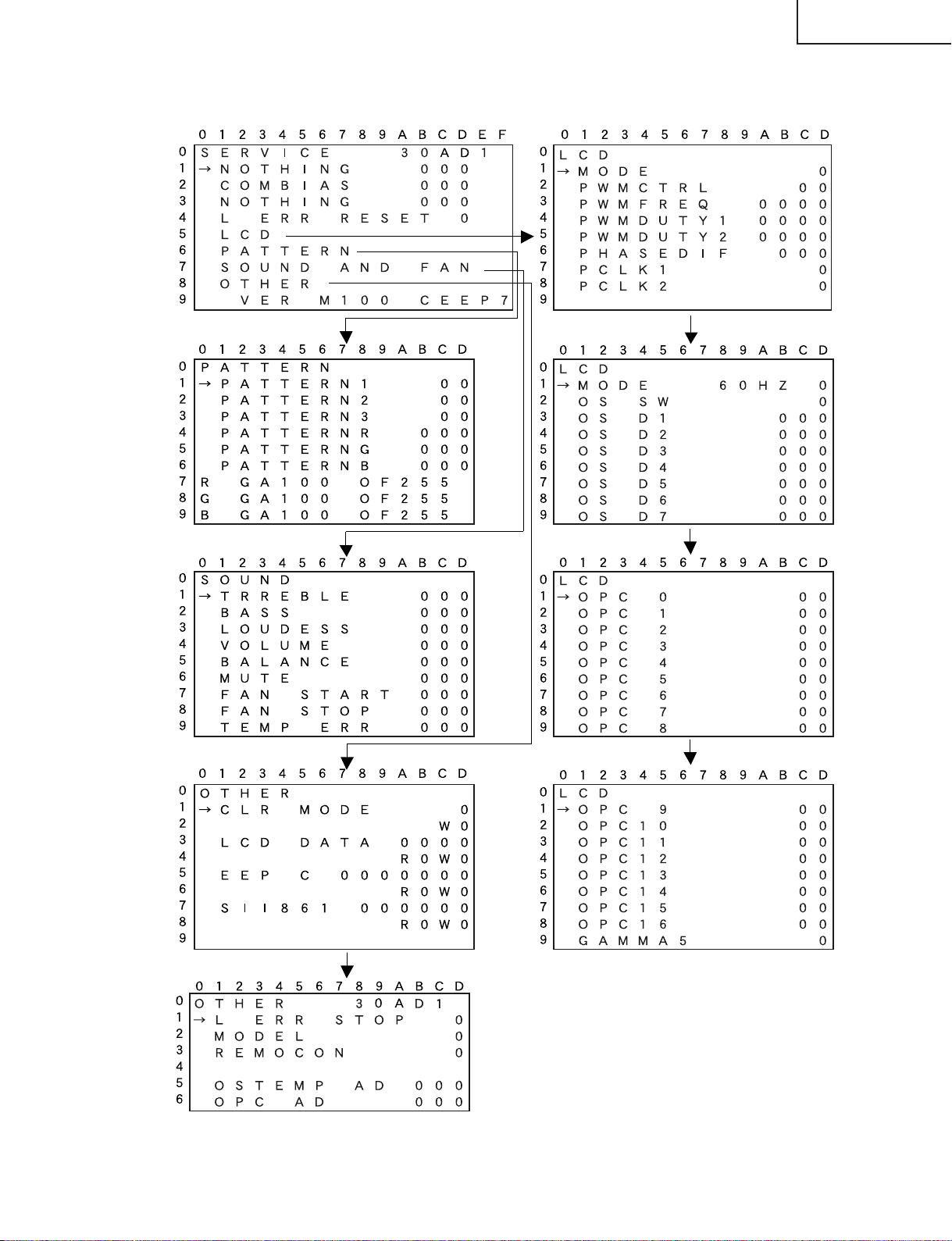
•List of process adjustment modes (Display)
Table of contents of process mode Page 0 LCD Page 1
LC-30HV6U
PATTERN Page 1
SOUND Page 1
OTHER Page 1
LCD Page 2
LCD Page 3
LCD Page 4
OTHER Page 2
21
Page 22
LC-30HV6U
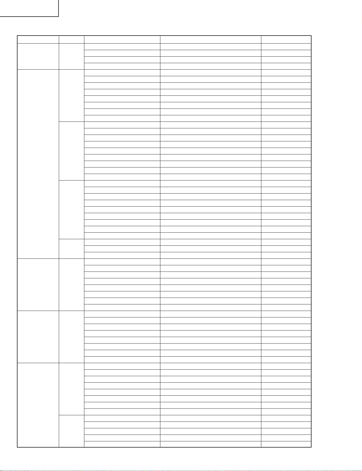
Process adjustment list
1st level Page Item Setting range Initial value
Contents 0 NOTHING 0~255 112
COM BIAS 0~255 87
NOTHING 0~255 41
L ERR RESET Zero clear 0
LCD 1 MODE 50Hz, 60Hz, PC 60Hz
PWM CTRL 0~7 7
PWM FREQ 0~4095 1289
PWM DUTY1 0~4095 0
PWM DUTY2 0~4095 0
PHASDIF 0~255 0
PCLK1 0~3 0
PCLK2 0~7 0
2 MODE 50Hz, 60Hz, PC 60Hz
OS SW 0~1 0
OS D1 0~255 110
OS D2 0~255 123
OS D3 0~255 135
OS D4 0~255 155
OS D5 0~255 167
OS D6 0~255 174
OS D7 0~255 179
3 MODE 50Hz, 60Hz, PC 60Hz
OPC 0 0~85 00
OPC 1 0~85 20
OPC 2 0~85 29
OPC 3 0~85 38
OPC 4 0~85 47
OPC 5 0~85 56
OPC 6 0~85 65
OPC 7 0~85 75
4 MODE 50Hz, 60Hz, PC 60Hz
OPC 8 0~85 85
OS AUTO 0~1 0
PATTERN 1 PATTERN1 0~14 0
PATTERN2 0~12 0
R GAMMA 20~180 Display only 100
R OFFSET 0~510 Display only 255
G GAMMA 20~180 Display only 100
G OFFSET 0~510 Display only 255
B GAMMA 20~180 Display only 100
B OFFSET 0~510 Display only 255
SOUND 1 100HZ 0~255 92
400HZ 0~255 96
1KHZ 0~255 145
4KHZ 0~255 187
10KHZ 0~255 187
FAN START 0~255 224
FAN END 0~255 230
TEMP ERR 0~255 55
OTHER 1 CLR MODE 1 digit 0~4 0
W –
LCD DATA 4 digits 0~F –
R/W –
EEPROM 7 digits 0~F –
R/W –
SII861 6 digits 0~F –
R/W –
2 L ERR STOP 0~1 0
MODE 0~4 0
REMOCON 0~1 0
OSTEMP AD 0~255 AD value
OPC AD 0~255 AD value
22
Page 23
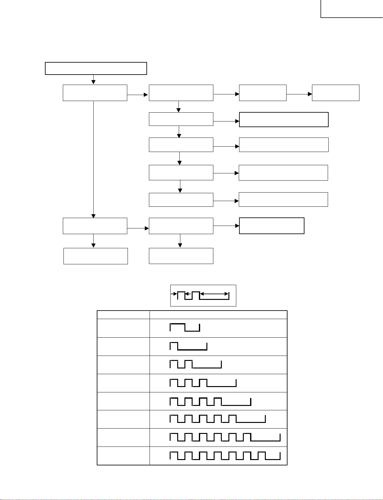
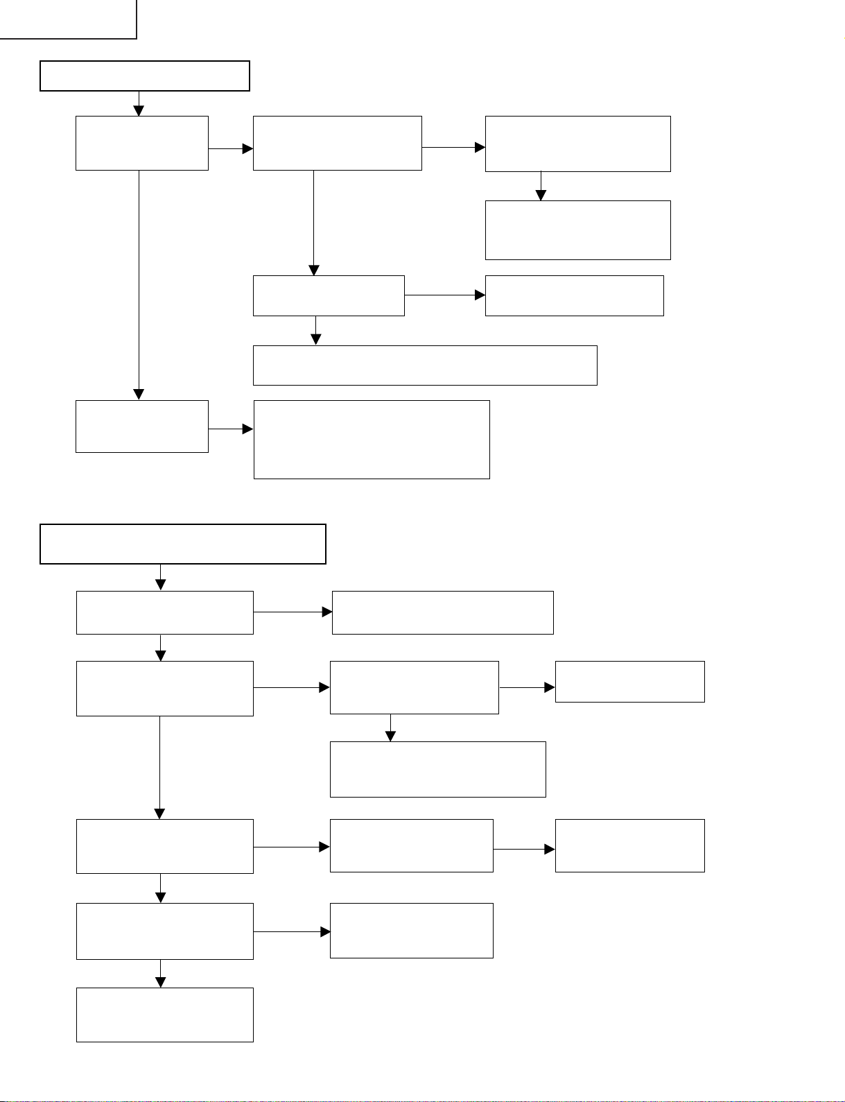
TROUBLE SHOOTING TABLE
No sound or picture comes out.
LC-30HV6U
(Display)
Does the power LED
light up in green.
YES
Is the Backlight off?
YES
Perform checking
around IC2204.
NO
NO
Is the power LED
blinking in red?
YES
Blinking once?
NO
Blinking twice?
NO
Blinking five times?
NO
Blinking seven times?
Is "LOSS OF SYNC"
displayed?
YES
Perform checking
around IC2208.
NO
YES
YES
YES
NO
Is the AC cord
normal?
NO
Replace the
AC cord.
To "The backlight does not go on"
Check the power unit.
Check the temperature of the set.
Check the 1-bit amplifier unit.
To "No picture comes
out"
Table of monitor power LED blinking timing at the time of error occurrence
250ms 1sec
Error type
Cable error
AVC-side power error
Blinking once: Slow
Lamp error
Blinking once: Fast
Monitor power error
Blinking twice
AVC temperature
error
Blinking three times
AVC fan error
Blinking four times
Monitor temperature
error
Blinking five times
Monitor fan error
Blinking six times
Monitor 1-bit error
Blinking seven times
LTD operation (1 cycle)
H: ON
L: OFF
H: ON
L: OFF
H: ON
L: OFF
H: ON
L: OFF
H: ON
L: OFF
H: ON
L: OFF
H: ON
L: OFF
H: ON
L: OFF
23
Page 24
LC-30HV6U
No picture comes out.
Is the RSET terminal (pin (3))
of IC2206 set to "H"?
YES
Is the clock (91.3 MHz) applied to
pin (102) of IC2206?
YES
Is the normal synchronization
signal is applied to pins (97),
(96) and (95) of IC2206?
YES
Check IC4903 and the ICs
(IC4701, IC4702, IC4901 and
IC4902) downstream from it.
Note that the unit should be replaced when the receiver IC (IC2206), HDCP key ROM (IC2208) or microprocessor
(IC2004) is replaced.
Applicable unit: DKEYHC094FE51
Data bit dropout (gray-scale-related)
NO
NO
NO
Perform checking around X2201
connected to pin (161) of IC2206.
YES
Is X2201 connected to pin (161) of
IC2206 oscillating (18.26 MHz)?
YES
Is IC2202 operating (CONFIG
ROM)?
YES
IC2206 is faulty.
NO
NO
Check X2201 and the
peripheral circuitry.
Perform checking
around IC2202.
Set PATTERN1 on the adjustment
process menu to "2". Is the gray
scale pattern displayed correctly?
YES
Set PATTERN3 on the adjustment
process menu to "1" to "3" (the QS
drive test pattern is displayed). Is
the gray scale displayed correctly?
YES
Set PATTERN3 on the adjustment
process menu to "4". Is the test
pattern displayed correctly at
intervals of one dot?
YES
Set PATTERN3 on the adjustment
process menu to "5". Is the test
pattern displayed correctly at
intervals of one dot?
YES
Perform checking between SC2201
and IC2206, between IC2206 and
IC4701 or between IC2206 and
IC4901.
NO
NO
NO
NO
Check the color signal in question
with the gray scale test pattern. Is
there a problem with the contact
and resistance between IC4501
and SC4601-4604?
YES
Perform checking around
IC4501 and SC4601-4604.
Perform checking around
IC4702 and IC4902.
Perform checking between
IC4701 and IC4501.
Perform checking between
IC4901 and IC4501.
NO
Check FFC
connected to
SC4601-4604.
PATTERN R, G and B become effective only when the monitor is started singly. Each can produce a solid
filled screen of 256-level gray scale, which can be used for IC wire connection checking when a certain gray
scale level is not produced.
24
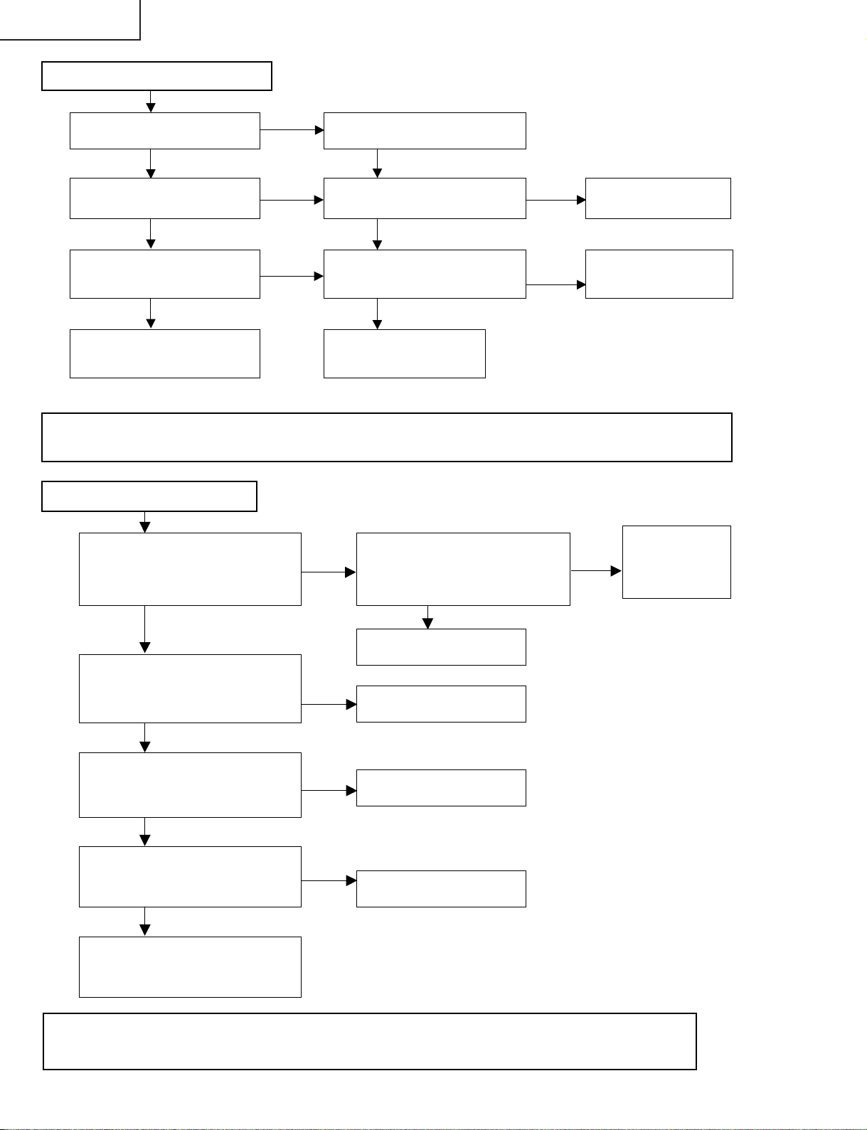
Page 25
Noise is caused to the moving picture when
the QS drive is set to ON.
LC-30HV6U
Is OSTEMP.AD on the 3rd page of the
process adjustment mode set to 255?
YES
Is the harness connected correctly
between the Thermistor PWB and
Inverter-4 PWB?
YES
Is the board-to-board connected
correctly between the Inverter-3 PWB
and Inverter-4 PWB?
YES
Is the harness connected correctly
between the Monitor PWB and
Inverter-3 PWB?
YES
Is the input voltage on pin (2) of
IC2004 (microprocessor) 5V?
YES
TH2001 thermistor
is faulty.
No
No
No
No
No
Check IC4701 and
IC4901 and the peripheral
circuitry.
Connect the harness
correctly or replace it.
Connect the board-toboard securely or replace
it.
Connect the harness
correctly or replace it.
Pin (2) of IC2004
(microprocessor) is faulty.
25
Page 26
LC-30HV6U
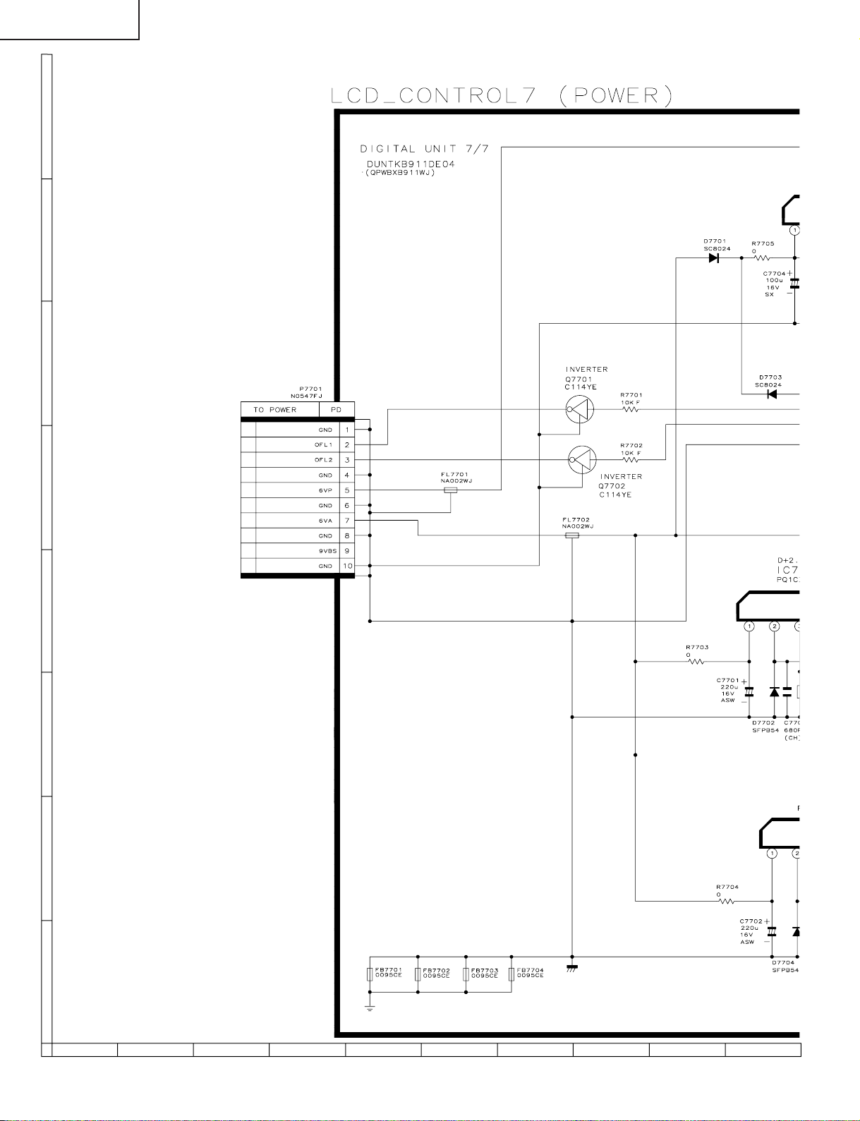
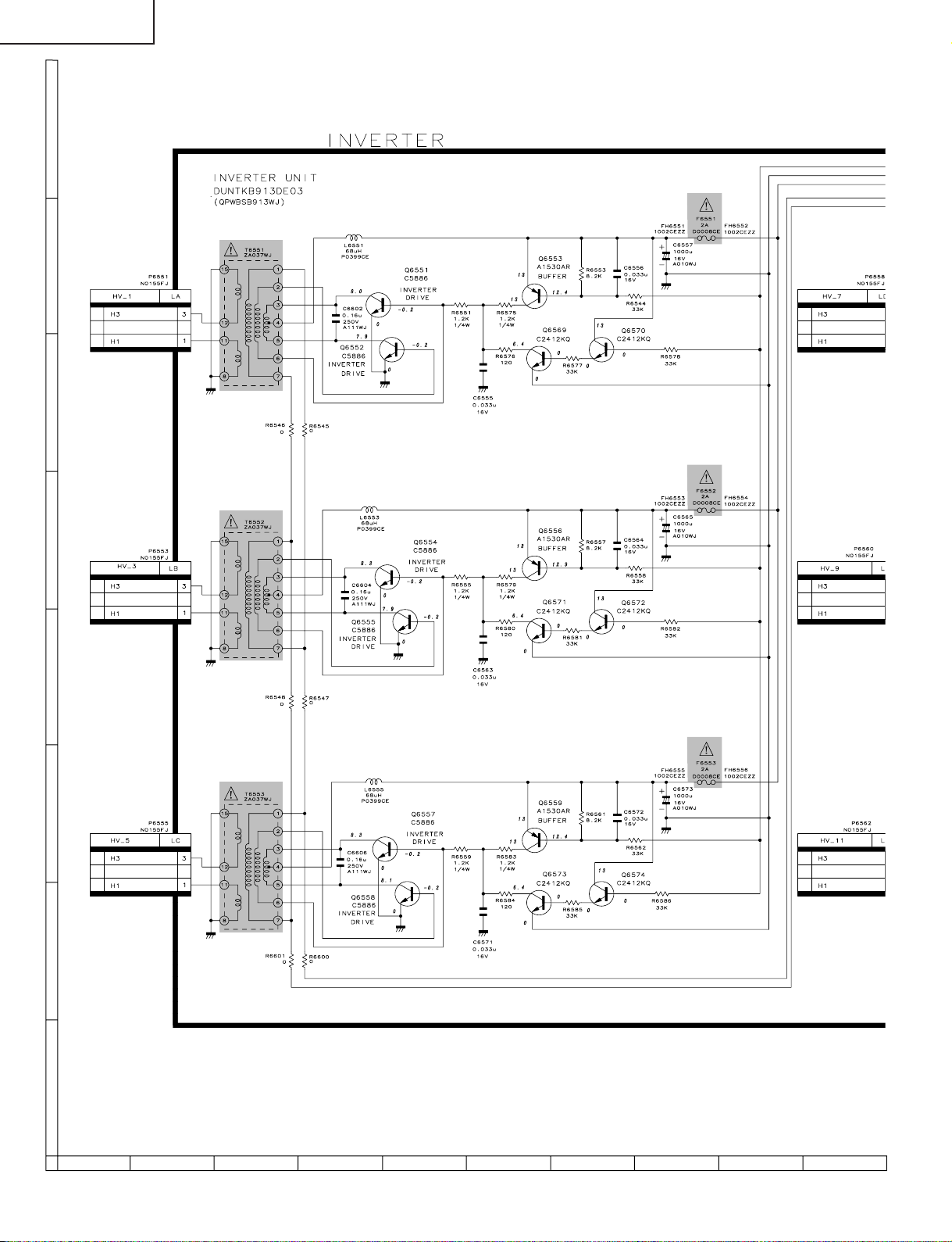
The backlight does not go on.
Is any of the fuses of
F6551-F6556
blown?
YES
Check the inverter
circuit downstream
from the blown fuse.
No
Is the control signal applied to
pin (8) (OFL1) and pin (9)
(OFL2) of P6564?
YES
Is power supplied to
Inverter PWB?
YES
Check the Lamp error detection circuit on the Inverter-GND
PWB.
Check the connection of the high-voltage
(pin (2)) wire on the side of the blown
fuse and check that of the counterpart
high-voltage (pin (2)) wire of the
fluorescent lamp on the opposite side.
No
No
Is the cord connected correctly
between the LCD Control PWB
and Inverter PWB?
YES
Check the peripheral circuitry of
IC4501 of the LCD Control PWB
and check the operation of
Q7701 and Q7702.
Check the 15V output on the
Power PWB.
No sound comes out. (Checking with the AVC
system connected)
Is power supplied to each IC
on the AUDIO PWB?
YES
Is the audio signal applied to
pin (7) (L-IN) and pin (9) (RIN) of P3804?
YES
Is the audio signal applied
to pin (13) and pin (15) of
P3803?
YES
Is the output signal from the
1-bit amplifier applied to
P3903?
No
No No
No
Check if 5V is supplied to the power
regulator circuit (IC3810, IC3812 and
IC3816) and pin (2) of P3804.
Is the audio signal applied to
pin (13) and pin (20) of
SC2202 on the Monitor PWB?
YES
Perform checking around Q2012 and
Q2014 and check the wire between
Monitor PWB and Audio PWB.
Are the MUTE circuits
(Q3804 and Q3805)
operating?
Perform checking around
IC2004, IC3804 and the 1bit amplifier.
NoNo
Check for the AVC
System side for output.
Perform checking
around IC3803 and
IC3808.
YES
Check if the internal/external
switching relay (RY3901)
functions correctly.
26
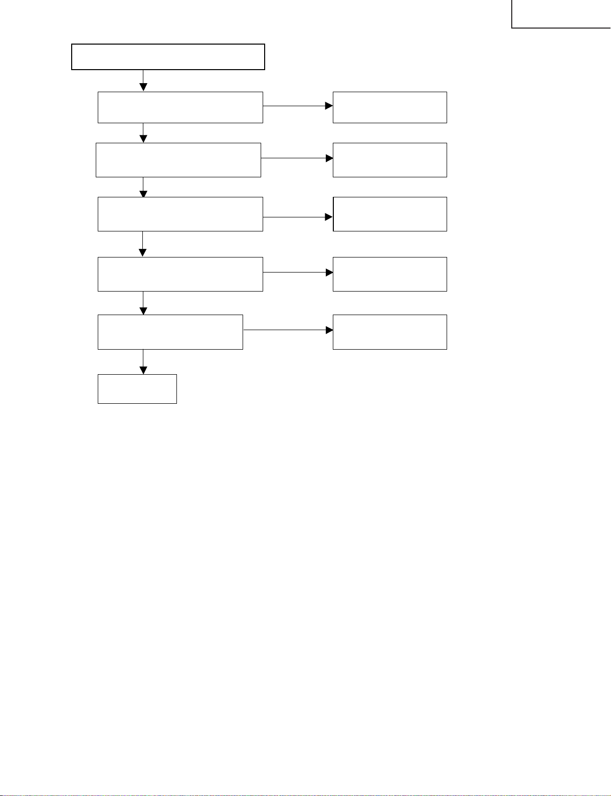
Page 27
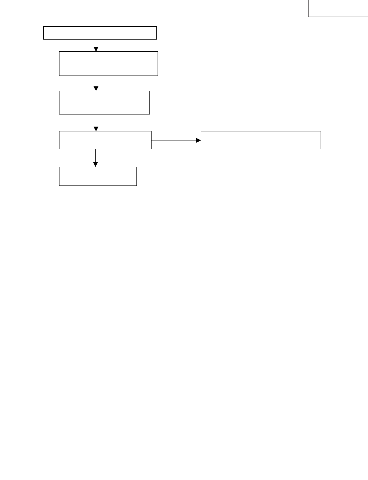
The whole screen is whitish (LCD power supply)
Remove the FFCs attached to SC4101
and SC4601- SC4604 (because the
panel may be broken).
YES
Check the power supplies.
Check the power supplies to
SC4101 and SC4102 in particular.
YES
LC-30HV6U
Is the voltage of emitter side of
Q4102 about 6V?
YES
Check the input/output
voltage of IC4103.
No
Perform checking around Q4101 and IC4101.
27
Page 28
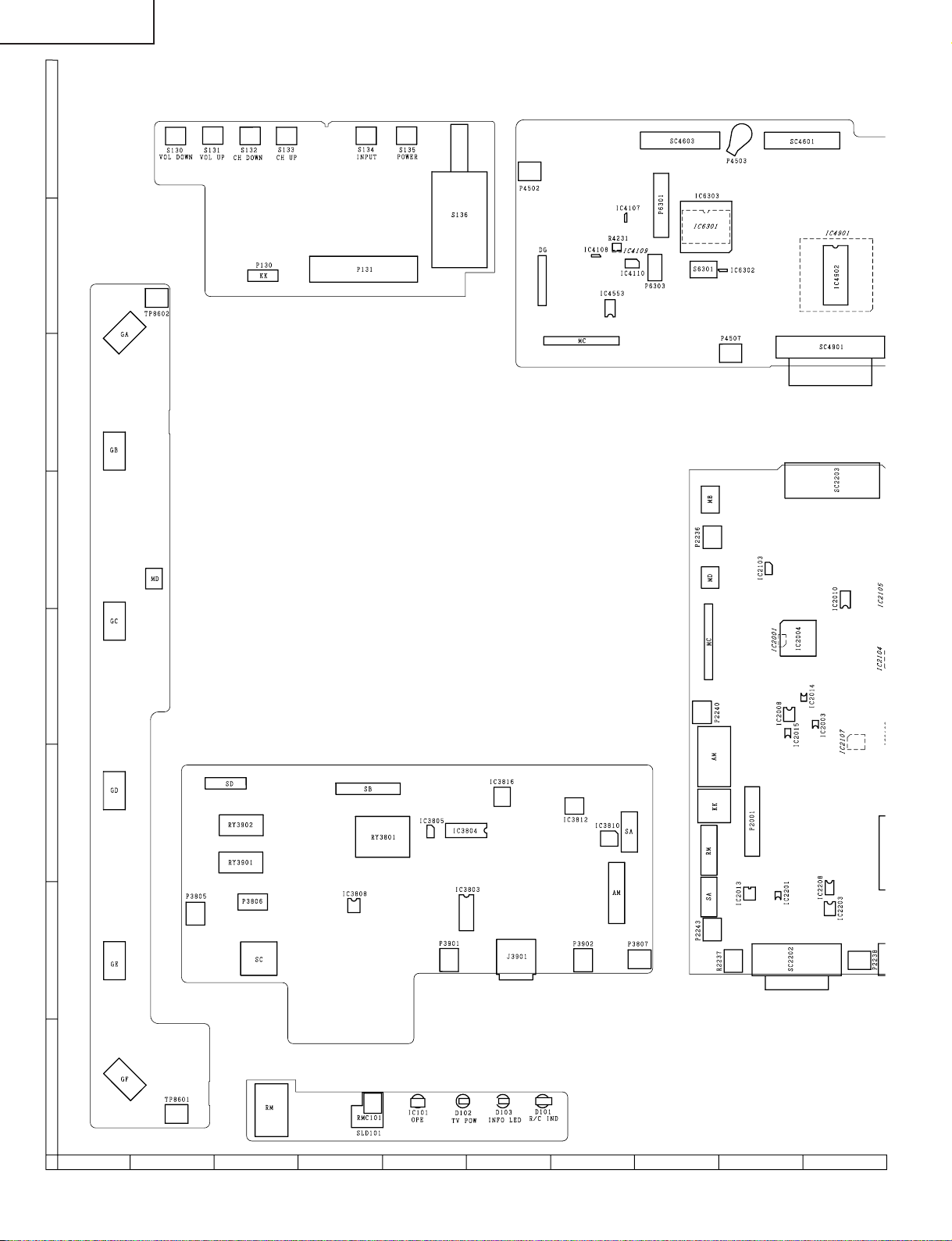
LC-30HV6U
CHASSIS LAYOUT (Display)
H
G
INV-GND PWB
F
KEY PWB
LCD CONTROL PWB
MAIN PWB
E
D
AUDIO PWB
C
B
R/C, LED PWB
A
87109654321
28
Page 29
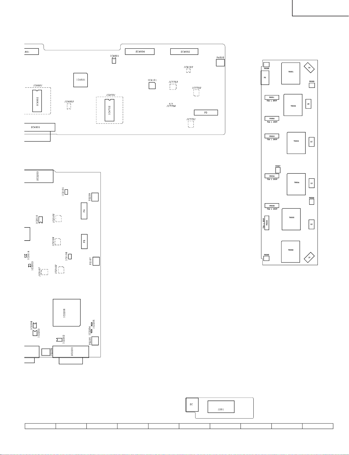
INV PWB
LC-30HV6U
SPEAKER-JACK PWB
29
1716 1918151413121110
Page 30
LC-30HV6U
R
x
h
e
C
p
)
k
C
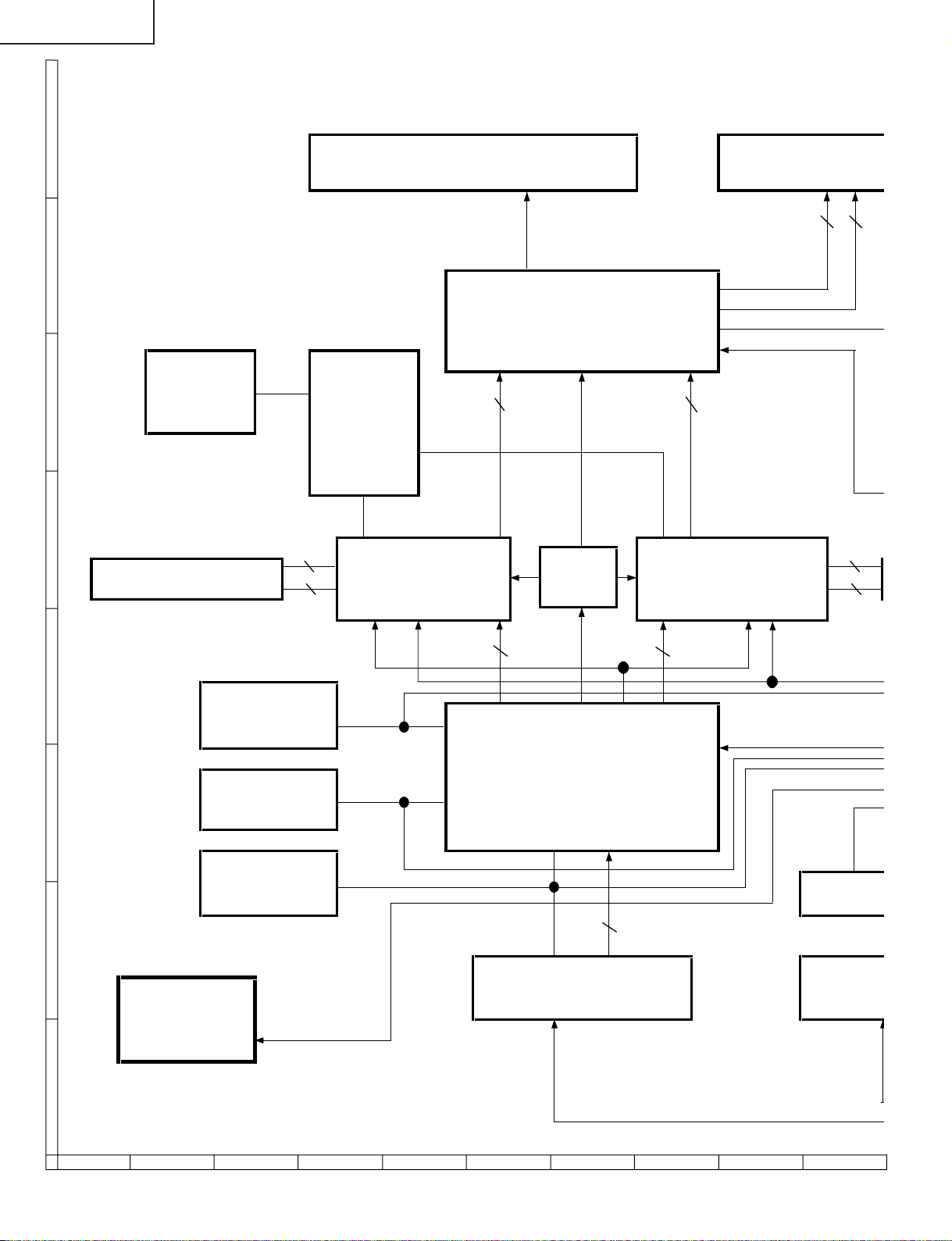
BLOCK DIAGRAM (Display)
H
G
F
LCD BackLight
OFL1,2 8 x 3 x 2 8
LCD Controller
IC4501 (A725WJ)
CONF
FLASH CONF
IC6301 CTRL RGB 8 x 3 RGB 8 x 3
(A372WJ) CPLD
IC6303
(A787WJ)
R RGB L
Lig
E
SDRAM (OS EVEN) QFP 208pin QFP 208pin
IC4702 (A312WJ)
D
E2P
C
B
Power PWB
(for Display)
A
E2P
E2P
16(data) OS Driver (EVEN) OS Driver (ODD) 16(data)
(OS EVEN) (OS ODD)
17(Address, etc) IC4701(A332WJ) IC4901(A332WJ) 17(Addr
INITIAL
ROM (128k)
IC2202 OSD
HDCP KEY
ROM (32k)
IC2208 IC2206 (SII861)
EDID
ROM (1k) ROM (8
IC2203 IC2008
TV POW
QFP 208
DVI Connector (24pin) System
SC2201 (ZA017WJ) SC2202
IC4903
CLOCK
BUFFER
RGB 8 x 3 HV, DE RGB 8 x 3
DVI Receiver
in (TMDS
TMDS 2 x 4
(TMDS) (TM
• TMDS 2 x 4
• DDC 3
OSD Drive Contol, Te
E2P
87109654321
30
Page 31

LCD Panel
B L RGB Thermistor
2 8 x 3 x 2
Gray Level
LC-30HV6U
Ope-Amp
IC4101(A706WJ)
Gray Scale Voltage Bias
COM Control
Light Control, Resolution Control, Test Pattern
16(data)
SDRAM (OS ODD)
IC4902 (A312WJ)
17(Address, etc)
Drive Contol, Test Pattern
MPU
OSD Control
IC2004 (IXA201WJ) Extension I/O
ROM (8k)
E2P
IC2008 Int. SP
Audio L/R
AUDIO UNIT
IC3804 (M62392FP)
VOL.CONT.
IC3803 (TA8184F)
Ext.SP (L/R)
R/C UNIT KEY UNIT
R/C, LED, OPC
RY3901
FAN
1-Bit Amp. Unit
(B2SX4102BU)
Audio Out
System Connector (20pin) Audio Connector
(TMDS) (8 pin)
SC2202 (Z2015CE) J2201(DA016WJ)
• Main Communication UART • FLASH Write Control
• Power Control • Remote Control Signal for SR
• Various Detection (Cable Connection, AVC System Startup, AC Startup)
31
• Ext.SP Out
AVC System
1716 1918151413121110
Page 32

LC-30HV6U
T
p
A
C
C
W
OVERALL WIRING DIAGRAM (Display)
H
KEY UNIT
P131
10 1
P130
5 1
QCNW-A481WJZZ
G
1
TO LAMP
3
P8601
FAN
INVERTER
F
TO LAMP
E
TO LAMP
GROUND
1
P8602
3
1
P8603
3
P8607
3
1
QCNW-B681WJQZ
QCNW-B815WJPZ
1-BIT AMP.
1
QCNW-B812WJQZ
1
1
SC4101
(30pin)
1
QCNW-B287WJZZ
SC4605
SC4603
(53pin)
50
2
LCD CON
1
P2103
3
1
3
1
QCN
3
SC4
(50
S
S
P2106
CN2001
P3801
D
TO LAMP
1
3
P8604
INVERTER
UNIT 2
1
P8605
P7551
C
TO LAMP
3
8
QCNW-B841WJQZ
18
P3903
15
P3802
15
QCNW-C090WJZZ
1
P3803
AUDIO UNIT
1
TO LAMP
B
3
P7553
P8606
P7557
P3904
51
QCNW-B682WJQZ
QCNW-B680WJQZ
6
P3801
1
10
P3804
QCNW-B816WJQZ
1
50
1
10
1
5
1
8
1
6
P2003
P2002
P2004
P2104
TO
M
1
R/C,LED
UNIT
A
P101
QCNW-B809WJQZ
8
87109654321
32
Page 33

QCNW-A480WJZZ
QCNW-A481WJZZ
1
GATE DRIVER
2 SOURCE DRIVER
3
SOURCE DRIVER
4 SOURCE DRIVER
5
SOURCE DRIVER
QCNW-A480WJZZ
LC-30HV6U
TO LCD PANEL UNIT
3 4 5
SC4601
(50pin)
D CONTROL UNIT
SC4901
103
SC2203
106
N2001
TO LAMP
MAIN UNIT
2003
2002
2004
P2101
P2102
SC4604
(53pin)
7
1
6
1
SC4602
(50pin)
P7701
1
1
CN723
1
QCNW-B683WJQZ
CN722
6
1
CN724
7
QCNW-B684WJQZ
10
QCNW-B813WJQZ
10
POWER UNIT
1
CN721
QCNW-B814WJQZ
9
1
P6564
9
INVERTER
UNIT
P6551
P6552
P6555
P6558
P6560
3
1
3
1
3
1
3
1
3
1
TO LAMP
TO LAMP
TO LAMP
TO LAMP
2104
QCNW-B685WJQZ
1
10
CN712
1
5
P201
SP_JACK UNIT
33
P6562
1716 1918151413121110
3
1
TO LAMP
Page 34

LC-30HV6U
DESCRIPTION OF SCHEMATIC DIAGRAM
VOLTAGE MEASUREMENT CONDITION:
1. When the exclusive-use AC adapter is used, the colour
bar signal of colour bar generator for service is input to
get the normal screen. When the audio is minimized,
the voltage value is measured with the 20 kΩ/V tester.
WAVEFORM MEASUREMENT CONDITION:
1. When the exclusive-use AC adapter is used, the colour
density, lightness and colour hue are set to the center
position, and the signal of colour bar generator for
service is observed to get waveform.
2. indicates waveform check points (See chart,
wavefor ms are measured from point indicated to
chassis ground.)
INDICATION OF RESISTOR & CAPACITOR:
RESISTOR
1. The unit of resistance “Ω” is omitted.
(K=kΩ=1000 Ω, M=MΩ).
2. All resistors are ± 5%, unless otherwise noted.
(J= ± 5%, F= ± 1%, D= ± 0.5%)
3. All resistors are Carbon type, unless otherwise noted.
C : Solid W : Cement
S : Oxide Film T : Special
N : Metal Coating
CAPACITOR
1. All capacitors are mF, unless otherwise noted.
(P=pF=mmF).
2. All capacitors are Ceramic type, unless otherwise
noted.
(ML) : Mylar (TA) : Tantalum
(PF) : Polypro Film (ST) : Styrol
CAUTION:
This circuit diagram is original one, therefore there may be a
slight difference from yours.
IMPORTANT SAFETY NOTICE:
PARTS MARKED WITH
IMPORTANT FOR MAINTAINING THE SAFETY OF
THE SET. BE SURE TO REPLACE THESE PARTS
WITH SPECIFIED ONES FOR MAINTAINING THE
SAFETY AND PERFORMANCE OF THE SET.
“å”
( )ARE
34
Page 35

LC-30HV6U
Ë
KEY Unit (Display)
H
G
F
E
D
C
B
A
654321
35
Page 36

LC-30HV6U
Ë
LCD CONTROL Unit-1/7 (Display)
H
G
F
E
D
C
B
A
87109654321
36
Page 37

LC-30HV6U
37
1716 1918151413121110
Page 38

LC-30HV6U
Ë
LCD CONTROL Unit-2/7 (Display)
H
G
F
E
D
C
B
A
87109654321
38
Page 39

LC-30HV6U
39
1716 1918151413121110
Page 40

LC-30HV6U
Ë
LCD CONTROL Unit-3/7 (Display)
H
G
F
E
D
C
B
A
87109654321
40
Page 41

LC-30HV6U
41
1716 1918151413121110
Page 42

LC-30HV6U
Ë
LCD CONTROL Unit-4/7 (Display)
H
G
F
E
D
C
B
A
87109654321
42
Page 43

LC-30HV6U
43
1716 1918151413121110
Page 44

LC-30HV6U
Ë
LCD CONTROL Unit-5/7 (Display)
H
G
F
E
D
C
B
A
87109654321
44
Page 45

LC-30HV6U
45
1716 1918151413121110
Page 46

LC-30HV6U
Ë
LCD CONTROL Unit-6/7 (Display)
H
G
F
E
D
C
B
A
87109654321
46
Page 47

LC-30HV6U
47
1716 1918151413121110
Page 48
LC-30HV6U
Ë
LCD CONTROL Unit-7/7 (Display)
H
G
F
E
D
C
B
A
87109654321
48
Page 49

LC-30HV6U
49
1716 1918151413121110
Page 50

LC-30HV6U
Ë
MAIN Unit-1/3 (Display)
H
G
F
E
D
C
B
A
87109654321
50
Page 51

LC-30HV6U
51
1716 1918151413121110
Page 52

LC-30HV6U
Ë
MAIN Unit-2/3 (Display)
H
G
F
E
D
C
B
A
87109654321
52
Page 53

LC-30HV6U
53
1716 1918151413121110
Page 54

LC-30HV6U
Ë
MAIN Unit-3/3 (Display)
H
G
F
E
D
C
B
A
87109654321
54
Page 55

LC-30HV6U
55
1716 1918151413121110
Page 56

LC-30HV6U
Ë
A UDIO Unit-1/2 (Display)
H
G
F
E
D
C
B
A
87109654321
56
Page 57

LC-30HV6U
57
1716 1918151413121110
Page 58

LC-30HV6U
Ë
A UDIO Unit-2/2 (Display)
H
G
F
E
D
C
B
A
87109654321
58
Page 59

LC-30HV6U
59
1716 1918151413121110
Page 60
LC-30HV6U
Ë
INVERTER Unit (Display)
H
G
F
E
D
C
B
A
87109654321
60
Page 61

LC-30HV6U
61
1716 1918151413121110
Page 62

LC-30HV6U
Ë
INVERTER GROUND Unit (Display)
H
G
F
E
D
C
B
A
87109654321
62
Page 63

LC-30HV6U
63
1716 1918151413121110
Page 64

LC-30HV6U
Ë
PO WER Unit (Display)
H
G
F
E
D
C
B
A
87109654321
64
Page 65

LC-30HV6U
65
1716 1918151413121110
Page 66

LC-30HV6U
Ë
R/C, LED Unit (Display)
H
G
F
E
D
C
B
A
654321
66
Page 67

LC-30HV6U
Ë
SPEAKER JACK Unit (Display)
H
G
F
E
D
C
B
A
654321
67
Page 68

LC-30HV6U
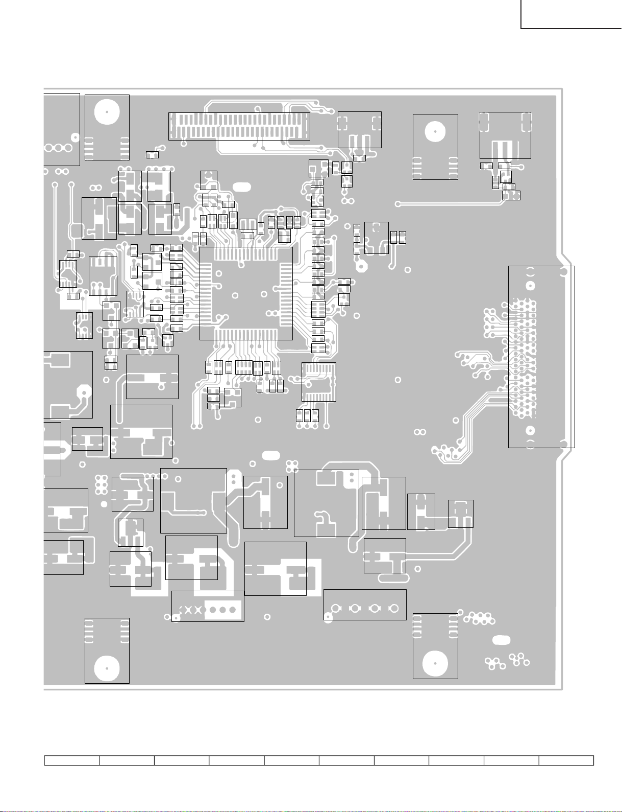
PRINTED WIRING BOARD ASSEMBLIES
Ë
Display
H
G
F
E
D
C
B
A
MAIN Unit (Component Side-A)
87109654321
68
Page 69

LC-30HV6U
69
1716 1918151413121110
Page 70

LC-30HV6U
C2029
Ë
Display
H
P2004P2104
P2002
P2243
P2237
P2003
G
IC2013
R2075
R2222
R2221
R2224
R2226
D2203
R2229
R2234
D2205
C2220
X2201
R2263
R2240
R2241
R2243
R2242
D2207
R2213
IC2203
R2235
R2233
R2232
R2264 R2231
FB2212
FL4904
R2238
R2239
F
SC2202
E
P2238
C2213
R2225
D
IC2202
R2254 R2230
R2253
IC2201
R2246
R2247
R2252
Q2201
Q2217
IC2208
R2249 R2217
R2248
R2251
Q2203
FL2212
R2228 R2216
Q2218
R2256
D2206
FL2211
FB2201 FB2202
R2257
FL2210
C2204
FL2209
D2202
R2258
FL2208
C2205
P2001
R2259
FL2207
R2260
R2279
D2002 R2006
FL2216
R2291
R2290
FB2210
FB2211
R2282
R2100
IC2015
R2101
IC2003
L2101
C2024
C2109
C2106
C2104
FL2215 FL2206 FL2214 FL2213FL2205
C2258
C2212
R2284
R2283
C2255
C
B
A
SC2201
R2205
R2261
C2211
R2262
R2278
R2276
R2244
C2237
C2232
C2225
C2221
P2235
IC2204
C2222
IC2205
C2235
MAIN Unit (Chip Parts Side-A)
FL2201
R2281
IC2206
FL2202
FL2203
R2286
FL2204
R2285
87109654321
70
Page 71
LC-30HV6U
R2100
R2101
L2101
IC2015
IC2003
C2024
P2240
C2029
IC2008
R2073
C2033
Q2006
Q2005
C2031
R2049 R2048
IC2014
Q2008 C2030
C2022
R2131
Q2011
Q2013
R2086
R2065
R2076
R2079
C2121
R2011
Q2009
C2027
C2026
R2027
R2033
R2034
R2030
R2028
R2023
R2041
R2044
R2064
C2032
D2010
R2092
R2010
C2009 R2019
D2001
R2099
R2042
R2018
R2072
R2077
R2078
C2020
R2008
R2017
R2071
CN2001
D2003
FL2001
R2014
IC2004
R2055
R2070
Q2007
R2016
R2054
R2085
R2015
R2058
R2024
R2020
C2010
TH2001
R2053
R2025
C2012
R2021
R2061
R2062
D2004
R2003
R2001
Q2004
R2012
R2026
C2013
R2029
R2031
R2035
R2032
R2038
R2037
R2039
C2015
R2045
R2046
R2047
R2052
R2069
R2043
IC2010
R2013
R2040
R2050
Q2010
P2106
R2129
Q2015 Q2016
R2114 C2108
IC2103
C2105
R2106
P2236
C2107
P2103
R2121
R2122
R2123
D2105
Q2105
SC2203
C2106
C2104
P2107
C2120
IC2106
C2119
L2103
C2111
P2102
C2113
C2115
L2104
71
P2101
C2117
C2101
C2102
IC2101
P2239
1716 1918151413121110
Page 72

LC-30HV6U
Ë
Display
H
G
F
E
D
C
B
A
MAIN Unit (Component Side-B)
87109654321
72
Page 73

LC-30HV6U
73
1716 1918151413121110
Page 74

LC-30HV6U
2
1
FB2016
Ë
Display
H
C2006
C2014
TL2042
C2011
TL2120
TL2043
TL2044
C2001
Q2002
R2002
TP2011
C2003
IC2001
R2009
TP2012
C2004C2002
TP2013
R2007
R2004
Q2001
C2016
R2063
R2082
R2091
TL2124
TL2019
R2057
R2051R2022
R2083
Q2014
R2060
R2081
R2094
R2096R2097
C2019
R2036R2056
R2095
Q2012
R2059
R2093
C2122
C2017
R2118
C2110
R2120
C2028
D2102
R2119
TL20
R2098
C2034
C2005
I
R2115
TL2047
TL2039
TL2041
TL2048
TL2040
TL2046
TL2045
G
R2074
R2005
TL2123
Q2003
F
E
C2021
R2080
FB2001
C2023
FB2002
D
D2103
R2109
R2110
C2112
R2107
TL2105
TL2104
IC2104
TL2103
IC2105
R2112
TL2111
TL2112
C2118
TL2109
TL2110
TL2108
D2104
R2111
R2113
C2116
TL2107
C2103
C
R2124
R2125
B
A
MAIN Unit (Chip Parts Side-B)
C2114
TL2121
TL2106
Q2104
Q2103
R2108
TL2101
TL2102
C2025
IC2102
R2102Q2101Q2102
R
R2
D2101
TL2119
R2116
R2127
74
87109654321
Page 75

C2017
R2118
R2120
C2028
D2102
R2119
C2025
R2102Q2101Q2102
R2116
R2098
C2005
R2115
D2101
C2034
TL2119
R2127
TL2026
TL2038
FB2016
IC2107
IC2102
R2103
R2104
R2126
TL2025
FB2015
R2128
TL2024
FB2014
R2117
TL2022
TL2023
FB2013
TL2021
FB2012
TL2244
TL2245
TL2246
TL2228
TL2020
FB2011
FB2010
TL2267
TL2219
TL2247
TL2243
TL2218
TL2217
TL2252
FB2206
TL2220
TL2221
TL2222
TL2223
FB2207
TL2012
TL2011
TL2201
R2288
R2289
R2287
R2280
C2218
D2220
C2215
D2210
TL2013
TL2014
FB2021
TL2010
TL2009
C2228
C2265
FB2022
TL2202
TL2203
TL2204
C2248
C2250
C2264 C2266
TL2015
TL2016
FB2023
TL2008
TL2006
TL2266
TL2268
TL2005
TL2265
TL2242
C2279
C2252
C2278
C2249
C2251
C2277
TL2030
TL2004
TL2003
TL2264
TL2241
TL2259
TL2031
FB2003
TL2007
TL2240
C2247
C2280
TL2037
FB2004
TL2002
TL2235
TL2258
TL2032
FB2005
TL2001
TL2234
TL2257
TL2233
C2245
C2276
TL2033
TL2034
FB2006
TL2256
TL2232
R2271
C2244
C2242
TL2035
FB2007
TL2122
TL2251
TL2250
C2243
C2281
R2227
R2292
C2268
R2270
R2269
D2218
Q2209
TL2036
FB2008
FB2009
TL2227
C2260
Q2213
R2274
Q2216
Q2212
Q2211
C2271
R2265
C2275
FB2209
R2250
TL2249
TL2248
TL2226
C2259
C2282
Q2214
Q2215
R2275
R2267
Q2210
R2266
C2261
C2262
TL2115
C2254
TL2225
R2268C2272
C2236
TL2114
R2245
TL2224
C2274
TL2113
C2018
Q2220
C2256
C2253
C2231
C2233
C2234
C2223
C2229
C2230
C2224
C2273
TL2116
C2219
Q2207
Q2208
TL2117
C2214
Q2204
C2270
R2273
TL2118
D2212
R2293C2269
Q2206
Q2205
C2207
D2211
C2209
D2215
C2210
D2214
D2217
C2206
D2201
C2201
FB2205
Q2202
C2263C2216
R2272
R2212
Q2219
D2219
C2217
C2227
C2203
R2201
C2208
D2216
R2215
R2297
R2214
R2206
R2219
D2209
R2218
R2220
R2209
R2296
R2202
D2204
FB2208
R2255
C2226
FB2203
D2208
TL2210
TL2215
TL2214
TL2213
R2204
C2202
R2210
FB2204
TL2211
TL2209
TL2208
TL2207
TL2206
TL2205
TL2216
LC-30HV6U
TL2212
R2298
TL2253
TL2229
TL2254
TL2230
TL2255
TL2231
TL2260
TL2236
TL2261
TL2262
TL2237 TL2238
75
TL2239
TL2263
1716 1918151413121110
Page 76

LC-30HV6U
Ë
Display
H
G
F
E
LCD CONTROL Unit (Component Parts Side-A)
R6312
C6310
C6312
R6313
C6304
IC6302
TL6301
R6304
C6311
P4507
R6305
R6311
P4503
C6306
C6305
R6307
R6315
C6301
FB6301
R6317 D6301
Q6302
R4908
R4907
R4906
R4905
SC4601
R4929
C4934
C4933
C4935
C4920
R4918 R4917 R4916 R4915
C4936
C4601
C4919
C4917
C4918
C4603
C4915
SC4901
C4602
C4914
C4916
IC4902
C4913
C4612
FL4608
TP4905
C4911
C4604
TP4906
C4912
C4910
C4939
C4938
TP4907
R4922 R4921 R4920 R4919
TP4901
TP4902
C4909
TP4904
R4901
TP4903
R4515
R4512
R4516
R4527
FL4516
FL4514 R4522
R4518
TP4501
FL4524
R4504
R4517
R4519
FL4521 FL4522
FL4523
FL4513 FL4515
TP4502
TP4503
TP4504
FL4519
R4526
R4576
FL4520
C4506
C4537
C4521
FL4517
R4577
R4525
C4593
R4573
C4505
FL4518
IC4501
IC4554
C4594
R4550
C4539
C4595
FL4502
R4501
FL4501
C4534
R4534
R4574
P6301
P6303
R6316
C6307 C6308
C6303
Q6301
SC4603
R6303
R6314
R6306
C6309
IC6303
S6301
D
P4502
C
C4148
R4228 C4165
Q4106
D4107
SC4101
B
Q4108
C4177
C4173
R4227
C4161
D4108
R4535
SC4605
FL4102
C4527
R4234
C4171
R4194
Q4105
L4108
C4170
L4103
C4162
C4166
R4233
R4237
R4225
IC4108
C4592
D4106
C4158 L4105
C4163
L4107
L4109
IC4553
C4159
L4104
C4157
R4217
R4219
R4221
D4105
R4231
R4232
R4224
C4179
IC4107
R4230
L4106
D4109
C4146 R4236
IC4110
FB4102
C4164
C4180
A
LCD CONTROL Unit (Chip Parts Side-A)
87109654321
76
Page 77

LC-30HV6U
R4577
FL4517
R4525
C4593
R4573
C4505
FL4518
IC4501
IC4554
C4594
R4550
C4539
C4595
FL4502
R4501
R4574
C4534
FL4501
R4534
FL4504
R4560
R4502
R4561
C4596
FL4503
R4505
C4730
C4729
C4731
C4717
FL4508
FL4510
FL4512
C4720
R4712
R4713
R4715 R4714
FL4505 FL4506
R4523
FL4507
FL4509
FL4511
C4719
C4718
C4732
R4508
R4521
R4511
C4715
R4615
R4510 R4509
R4613 FB4601
IC4702
C4714
C4716
C4713
IC4601
C4610
C4611
C4711
C4712
C4710
C4734
C4735
R4614 FB4602
R4719 R4718 R4717 R4716
R4616
FL4607
C4606
R4723
TP4702
TP4701
TP4703
C4502
TP4704
C4701 C4702
C4608
C4192
R4196
C4156
SC4604
R4200
C4112
R4188
R4187
R4181
R4193
R4184
R4191
R4186
R4185
C4155
R4182
C4147
R4177
R4174
R4176 R4175
C4141
R4166
R4165
R4167
R4169 R4168
IC4101
C4137
R4157
R4159 R4158
C4129
R4147
R4146
R4148
R4150 R4149
R4140
C4115
R4130
R4139
C4121
R4141
R4134 R4133
R4142
R4132
P4504
R4124
R4125
R4118
R4113
C4124 R4173
R4129
R4240
R4135 R4131 R4127
R4122
SC4606
C4113
R4120
Q4102
FL7703
C7707
C7706
C4111
FL7704
C7704
R4117
C7710
C7711
C7709
SC4602
L7704
L7702
C7713
L7703
L7701
C4613
FL4609
C7702
C7701
SC4607
FB7702
FL7701
P7701
P7702
FB7703
FDC1
FL7702
FB7704
P4505
FB7701
1716 1918151413121110
77
Page 78

LC-30HV6U
2
0
3
Ë
Display
H
G
F
E
LCD CONTROL Unit (Component Parts Side-B)
TL4641
TL7714
TL7713
TL7708
TL4885
TL4886
TL4831
TL4811
TL4740
TL7712
TL4729
TL4637
TL4634
TL4623
TL7707
TL7711
TL4640
TL4862
TL4671
TL4628
Q7702
TL7704
TL4626
TL4850
R7702
TL7716
TL4834
TL4855
TL4643
TL4847
Q7701
TL7715
TL4853
IC7702
R7701
TL4822
TL4718
TL4841
TL4839
TL4845
TL4832
TL4835
C4108
R7711
FB7706
TL4837
TL4101
R7704
IC7701
TL4765
TL4829
R7719
TL4826
IC4103
R7714
R7713
R7707
C7705
TL4781
TL4818
TL4823
R7708R7709
TL4812
TL4815
TL7720
TL7719
TL4796
TL4805
D7704
TL4802
TL4809
TL4808
TL4799
TL4797
R7712
R7706
C7703
TL4791
R4106R4110
TL7721
TL4785
TL4788
C4103C4110
D7701
FB7705
D7702
TL4842
TL4782
R4111
R4104
R4109
R4108
R4105
R7705
D7705
TL4605
TL4770
TL4776
TL4773
TL4767
D7703
C7712R7720
R7703
TL4614
TL4753
TL4759
TL4625
R7721
Q4101
D7706
C7708R7718
TL4663
TL4757
R4101
IC7703
R7716
TL4817
TL4828
TL4748
TL4622
R7717
TL4750
TL4819
R7715
Q7703
IC7704
TL4749
R4102
C4101
TL7722
R7710
TL4806
C4102
TL4801
TL4792
TL4701
R4123
R4115
R4126
R4119
R4114
R4112
R4212
TL4790
R4215
TL4654
D
FDC2
TL4849
C
TL4804
TL4814
TL4825
B
TL7709
TL7705 TL7703
TL7701
TL4125
R4214
C4135
C4139
C4114
IC4104
C4107
TL4769
TL4772
TL4784
R4138
C4104
R4156
R4161
R4137C4125
R4136
C4105
TL4117
R4145
C4183
TL4775
R4155
R4160
R4144
TL4869
C4127
R4143
R4151
C4191
TL7702
TL4846
TL4851
TL4854
TL4118
R4154
TL4780
TL4857
TL4866
R4153
C4136
R4216R4152
TL4867
R4164
IC4105
C4126
TL4860
TL4863
R4163
C4122
TL4848
TL4852
TL4840
TL4838
R4162
R4172
TL4843
TL4861
TL4793
R4171
C4123
TL4836
R4170
C4184
TL4830
TL4833
C4153
C4190
TL4824
TL4827
TL4821
R4180
R4192
R4183
R4190
TL4820
TL4813
R4201
R4199
TL4810
TL4816
TL4777
TL4807
TL4803
TL4800
TL4763
TL4798
TL4794
TL4760
FL4604
TL4756
TL4758
C4607
TL4774
TL4779
TL4783
TL4789
R4702
R4724
C4605
TL4786
R4703
TL4768
TL4771
C4708C4705C4704C4707
TL4904
TL4937
C4703C4706R4701
C4733
TL4764
C4709
FL4603
TL4905
TL4752
TL4938
TL4907
TL4754
TL4940
TL4915
TL4908
TL4941
TL4948
TL4949
TL4916
TL4917
TL4950
TL4951
IC4701
TL4918
TL4924
TL4959
TL4761
TL4960
TL4925
TL4928
TL4927
TL4762
TL4963
TL4962
D4501
TL4901
TL4903
TL4902
C4721
FB4505
C4536
R4705
R4711
R4704
C4722
C4727
C4728
C4723
R4706
C4532
C4725
C4726
R4580
R4710
R4709
C4724
C4526
R4707
C4530
C4531
R4524
C4540
R4708
R4556
C4538
C4533
C4535
R4558
C4528
FB4503
R4536
R4507
R4557
R4559
R4538
TL4712
R4551
IC4502
C4529
R4554
R4555
R4540R4537
FB4903
FB4902
R4572
C4525
C4511
IC4503
C4523
TL4684
C4518
R4914
R4912
C4520
R4553
R4503
C4517
C4929
C4522
IC4903
R4552
C4519
R4582
R4913
TL4935
R4581
R4529
FB4901
R4930
R4579
R4903
R4904
TL4617
R4578
T
C4908C4905C4904C4907C4903C4906
TL49
C49
R49
A
LCD CONTROL Unit (Chip Parts Side-B)
87109654321
78
Page 79

LC-30HV6U
517
3
C4929
C4522
R4552
IC4903
C4519
R4582
R4581
R4913
TL4935
R4529
FB4901
R4930
R4579
R4903
R4904
TL4617
R4578
C4908C4905C4904C4907C4903C4906
TL4926
C4937
R4902
TL4619
TL4607
TL4685
TL4609
TL4934
TL4909
R4923
TL4670
R4924
TL4929
TL4727
R4925
TL4737
TL4730
TL4910
TL4739
TL4911
TL4943
TL4912
TL4944
TL4741
TL4724
FL4602
IC4901
TL4913
TL4945
TL4735
TL4721
TL4920
TL4946
TL4921
TL4953
FL4601
TL4922
TL4954
TL4751
TL4955
TL4706
TL4709
TL4923
TL4957
TL4755
TL4697
TL4703
TL4930
TL4691
TL4694
TL4931
TL4965
TL4682
TL4688
TL4967
TL4676
TL4679
TL4932
TL4968
TL4667
TL4673
TL4733
TL4664
C4921
TL4936
TL4658
TL4933
TL4969
TL4661
TL4651
R4911
TL4653
TL4645
C4925
C4926
C4922
C4923C4928
C4924
TL4970
TL4648
TL4639
C4927
TL4630
TL4636
R4910
R4909
TL4611
TL4613
TL4633
TL4880
TL4878
TL4615
TL4876
TL4874
TL4864
TL4872
R4604
R4605
R4606
R4601
TL4870
TL4655
TL4714
TL4717
TL6311
R4603
TL4711
IC4602
R4607
C4609
R4602
TL4690
TL4732
TL4708
TL4720
TL4642
TL4699
TL4723
TL4726
TL4728
IC6301
TL4919
TL4705
TL4966
TL4702
TL4669
TL4914
TL4696
TL4964
TL4678
TL4672
TL4693
TL4681
TL4675
TL4687
TL4666
TL4662
TL4660
TL4657
TL4844
TL4646
TL4652
TL4644
TL4650
TL4961
TL4635
C6302
TL4631
TL4638
TL4629
R6301
R6302
TL4958
TL4620
TL4618
TL4624
TL4604
TL4956
TL4612
TL4610
TL4616
TL6302
TL6303
TL6304
TL6305
TL6306
TL6307
TL6308
TL6309
TL6310
TL4603
TL4608
TL4606
TL4602
TL4601
TL4906
TL4715
TL4700
TL4747
R4539
C4167
TL4746
IC4109
R4226
C4501
TL4787
R4220
C4168
R4229
TL4710
TL4738
TL4745
R4218
R4238
TL4939
TL4947
TL4766
TL4736
Q4104
TL4734
TL4731
Q4103
TL4692
TL4722
TL4713
TL4725
TL4942
TL4873
TL4716
TL4719
D4103
D4104
TL4743
TL4742
TL4744
TL4707
R4222
R4250
TL4128
TL4704
TL4698
TL4795
C4174
TL4686
TL4683
R4206
R4207
L4110
C4172
TL4680
TL4674
TL4695
TL4689
TL4668
TL4865
TL4677
TL4884
Q4107R4223
C4160R4213
C4169
FL4103
TL4656
TL4881
TL4659
TL4665
TL4627
C4176
TL4877
TL4778
C4175
R4235
TL4856
TL4859
TL4890
TL4858
TL4649
R4251
TL4123
TL4124
TL4107
C4178
TL4122
TL4882
C4185
TL4131
TL4127
TL4875
TL4871
TL7706
TL4102
TL4111
TL4116
TL4120
TL4121
TL4647
TL4883
TL4105
TL4126
TL4129
TL4112
TL4114
TL4119
TL4879
TL4868
TL4110
TL4113
TL4632
TL4621
TL4952
TL4103
TL4104
TL4106
TL4115
TL4108
TL4130
TL4109
79
1716 1918151413121110
Page 80

LC-30HV6U
Ë
Display
H
G
F
E
D
C
B
A
AUDIO Unit (Component Side)
654321
80
Page 81

LC-30HV6U
P3806
P3805
RY3901
P3906
C3902
P3904
C3904
C3905
R3903
D3901
R3902
Q3901
R3901
P3905
D3804
C3901
C3838
R3846
R3848
C3834
R3853
R3850
C3847
R3851
C3832
R3839
R3840
R3833 C3839
D3805
R3849
IC3808
R3847
C3826
C3850
C3828
R3837 R3834
R3829
R3828
R3841
C3833
C3830
C3843
C3841
C3829
R3825
R3826
C3831
Q3802
C3824
C3825
R3845
R3832
C3835
R3844
D3801
Q3801
C3802
R3842
R3831
C3815
C3813
R3804
R3805
R3812
D3802 R3830
P3901
D3803
R3815
C3817
C3812
C3810
C3853 R3818
C3806
C3823 R3821
C3821 R3819
R3816
IC3803
R3817
C3819
C3820
C3906
FB3901
C3876
C3808
FB3902
C3848
C3914
C3811
C3809
C3822
D3906
C3913
R3811
C3818
D3905
R3809
C3804
R3810
C3816
C3814
C3805
R3807
J3901
R3802
R3801
R3813
R3823
C3801
C3871
C3870
C3882
X3801
C3865
C3864
R3806
R3820
C3878
FB3904
D3904
C3867
R3870
C3869
C3912
C3877
C3875
IC3814
R3872
FB3903
C3907
C3879
C3911
C3868
D3903
R3871
C3874
C3861
C3880
C3884
C3860
C3883
R3843
C3863
C3862
P3902
R3824
R3865
R3866
R3864
R3860
R3814
R3867
P3804
P3807
P3801
IC3810
D3808
C3855
R3836
C3836
R3838
R3862
R3863
IC3812
C3881
C3854
C3856
IC3813
C3857
C3859
D3811
C3858
D3807
C3852
IC3816
R3808
R3803
C3807
Q3808
Q3807
L3801
IC3804
Q3806
R3835
R3827
R3852
IC3805
Q3803
C3827
R3856
D3806
C3842
RY3801
R3822
R3861
P3803
R3875
Q3805
C3886
C3846 R3855
C3885
Q3804
C3845 R3854
C3844
C3840
Q3902 D3902
R3904
R3908
R3907
C3908
RY3902
C3910
P3903
C3909
R3905
R3906
C3903
Ë
Display
H
G
F
E
D
C
B
A
AUDIO Unit (Chip Parts Side)
81
654321
Page 82

LC-30HV6U
Ë
Display
H
G
F
E
INVERTER Unit (Component Parts Side)
D
Q6567
P6565
C6612
Q6566
Q6580
R6597
R6596
Q6579
R6571
C6595
R6554
R6598
R6573
C6596
R6595
Q6568
R6572
R6574
C6597
L6561
FH6561 FH6562
Q6578
R6593
Q6564
C6610
R6599 R6549
Q6563
Q6577
R6592
R6567
C
T6556
T6555
C6587
R6594
R6569
C6588
Q6565
R6591
R6568
R6570
FH6560
FH6559
C6589
L6559
B
R6590
R6566
R6565
Q6576
C6580
R6589
Q6575
Q6562
R6587
R6563
C6608
C6581
Q6560
T6554
R6588
C6579
R6564
Q6561
R6550 R6600
FH6558
FH6557
P6567
L6557
P6562
P6560
P6568
P6558
A
INVERTER Unit (Chip Parts Side)
87109654321
82
Page 83

LC-30HV6U
P6567
L6557
R6559
Q6557
FH6556
FH6555
R6586
R6562
R6561
Q6574
C6572
R6585
Q6573
Q6559
R6583
R6584
C6571
R6560
Q6558
C6606
R6601 R6547
T6553
P6555
L6555
C6573
L6553
C6565
FH6554
FH6553
R6548
Q6555
R6556
R6580
Q6572
Q6571
R6581
C6563
C6604
R6582
R6557
C6564
Q6556
R6579
R6558
T6552
P6553
R6555
Q6554
FH6552
FH6551
R6545
L6551
C6557
P6569
R6546
Q6552
P6564
C6602
T6551
Q6551
R6551
P6551
R6576
Q6570
Q6569
P6566
R6577
C6555
R6578
R6553
C6556
R6544
Q6553
R6575
R6552
83
1716 1918151413121110
Page 84

LC-30HV6U
Ë
Display
H
G
F
INVERTER-GND Unit (Component Parts Side)
E
D
P8606
C
R8614 R8615 C8602 C8605
TP8601
R8604
D8604
D8603
R8608
C8606 C8612
R8607
C8603 C8609
Q8605
Q8603
Q8602
R8612
D8608
R8611
D8607
P8605
P8604
R8603
B
INVERTER-GND Unit (Chip Parts Side)
A
87109654321
84
Page 85

LC-30HV6U
P8603
R8602
P8607
R8613
85
C8604
C8607
C8610
D8601
R8606
Q8601 Q8604 Q8606
D8605
P8602
R8609
R8610
D8606
R8601
C8608
D8602
R8605
P8601
C8601
C8611
TP8602
1716 1918151413121110
Page 86

LC-30HV6U
Ë
Display
H
G
F
E
D
C
B
A
POWER Unit (Side-A)
654321
86
Page 87

LC-30HV6U
Ë
Display
H
G
F
E
D
C
B
A
POWER Unit (Side-B)
654321
87
Page 88

LC-30HV6U
Ë
Display
H
G
F
P101
C101
(Component Parts Side)
IC101
C103
D104
RMC101
SLD101
R114
C102
C104
C105
D102
C106
R111
R113
D103
R112
Q106
R109
R102
Q103
R110
R108
R103
R101
D101
R107
Q102
Q104 R104
Q101
R115
R105
R106
Q105
E
(Chip Parts Side)
R/C, LED Unit (QPWBSC097WJN1)
D
C
(Component Parts Side)
C201
C203
FB203
FB204
D201
J201
D202
C204
P202
FB201
B
P201
FB202
C202
D203
C205
C206
D204
(Chip Parts Side)
A
SPEAKER JACK Unit (QPWBSC099WJN1)
654321
88
Page 89

LC-30HV6U
Ë
Display
H
G
F
(Component Parts Side)
E
S133
D131
R132
R130
S131
D130
S132
R131
P132
D
S130
C
S135S134
D132
S136
B
P130
P131
(Chip Parts Side)
KEY Unit (QPWBSC098WJN1)
A
654321
89
Page 90

LC-30HV6U
PARTS LIST
PARTS REPLACEMENT
Replacement parts which have these special safety characteristics
identified in this manual; electrical components having such features
are identified by
and Schematic Diagrams. The use of a substitute replacement part
which dose no have the same safety characteristic as the factory
recommended replacement parts shown in this service manual may
create shock, fire or other hazards.
"HOW TO ORDER REPLACEMENT PARTS"
To have your order filled promptly and correctly, please furnish the
following informations.
1. MODEL NUMBER 2. REF. NO.
3. PART NO. 4. DESCRIPTION
in USA: Contact your nearest SHARP Parts Distributor to order.
Ref. No. Part No. ★ Description Code
å and shaded areas in the Replacement Parts Lists
For location of SHARP Parts Distributor, Please call TollFree; 1-800-BE-SHARP
★ MARK: SPARE PARTS-DELIVERY SECTION
LISTE DES PIECES
CHANGE DES PIECES
Les pi`eces de rechange qui pr élelesentent ces caract éleristiques
sp éleciales de s élecurit éle, sont identifi élees dans ce manuel :
lespi`eces élelectriques qui pr élesentent ces particularit éles, sont
rep éler élee par la marque
pi`eces et dans les diagrammes sch élematiques.
La substitution d'une pi`ece de rechange par une autre qui ne pr
éLesente pas les m éoemes caract éLeristiques de s élecurit éle que
la pi`ece recommand élee parl'usine et dans ce manuel de service,
peut provoquer une éLelectrocution, un incendie ou toutautre sinistre.
"COMMENT COMMANDER LES PIECES DE
Pour que votre commande soit rapidement et correctement remplie,
veuillez fournir les renseignements suivants.
1. NUMERO DU MODELE 2. NO. DE REF
3. NO. DE PIECE 4. DESCRIPTION
in CANADA: Contact SHARP Electronics of Canada Limited
Phone (416) 890-2100
Ref. No. Part No. ★ Description Code
ået sont hachur élees dans les listes de
RECHANGE"
PRINTED WIRING BOARD ASSEMBLIES
(NOT REPLACEMENT ITEM)
DUNTKC009FE06 – MAIN Unit(AVC System) —
DUNTKC015FE06 – POWER Unit(AVC System) —
DUNTKC069DE22 – FRONT Unit(AVC System) —
DUNTKC070DE22 – AUDIO I/F Unit —
(AVC System)
DUNTKC083FE02 – AV Unit(AVC System) —
CPCi-A005WJ65 J PC I/F Unit(AVC System) CR
DUNTKB911FE04 – LCD CONTROL Unit —
(Display)
DUNTKB913FE03 – INVERTER Unit(Display) —
DKEYHC094FE51 J MAIN Unit(Display)
DUNTKC096DE02 – AUDIO Unit(Display) —
DUNTKC097DE02 – R/C,LED Unit(Display) —
DUNTKC098DE02 – KEY Unit(Display) —
DUNTKC099DE02 – SPEAKER-JACK Unit —
(Display)
DUNTKC101DE02 – INVERTER-GND Unit —
(Display)
RDENCA052WJZZ – POWER Unit(Display) —
B2SX4102BT J 1-Bit Amplifier Unit BL
(A2SX4102BT)
DSETGC009FE08 J AVC System Unit,
for Service
NOTE: This service manual accordingly describes the display
alone. For the entire AVC System, refer to the LC-37HV6U
Service Manual.
LCD PANEL
NOTE: THE PARTS HERE SHOWN ARE SUPPLIED AS AN
ASSEMBLY BUT NOT INDEPENDENTLY.
RLCDTA026WJZZ J 30" LCD Panel Unit EP
90
Page 91

LC-30HV6U
Ref. No. Part No. ★ Description Code Ref. No. Part No. ★ Description Code
DUNTKB911FE04
LCD CONTROL UNIT (Display)
INTEGRATED CIRCUITS
IC4101 RH-iXA706WJZZQ J IR3E12M1 AN
IC4103 VHiNJM4580V-1Y J NJM4580V AE
IC4107 VHiLT1615ES-1Y J LT1615ES5 AP
IC4108 VHiLT1617ES-1Y J LT1617ES5 AP
IC4109 VHiLTC1872+-1Y J LTC1872ES6 AR
IC4110 VSSi4884DY+-1Y J SI4884DY-T1 AG
IC4501 RH-iXA725WJZZQ J LR38854 BC
IC4553 VHiLV244AT+-1Y J SN74LV244APWR AF
IC4601 VHiTC74AC8T-1Y J TC74AC08FT AF
IC4701 RH-iXA332WJZZQ J XC2S150-5PQ208 BM
IC4702 RH-iXA312WJN1Q J MT48LC2M32B2TG AX
IC4901 RH-iXA332WJZZQ J XC2S150-5PQ208 BM
IC4902 RH-iXA312WJN1Q J MT48LC2M32B2TG AX
IC4903 VHiTC74AC8T-1Y J TC74AC08FT AF
IC6301 RH-iXA732WJZZQ J MBM29LV800TA AV
IC6302 VHiBD4729G+-1Y J BD4729G-TR AD
IC6303 RH-iXA787WJZZQ J XC95144XL-10TQ AY
IC7701 VHiPQ1CZ21H-1Y J PQ1CZ21H2ZP AH
IC7702 VHiPQ1CZ21H-1Y J PQ1CZ21H2ZP AH
IC7703 VHiPQ3DZ13U-1Y J PQ3DZ13U AG
IC7704 VHiBD4746G+-1Y J BD4746G-TR AD
TRANSISTORS
Q4101 VS2SD1664R+-1Y J 2SD1664R AC
Q4102 VS2SD1664R+-1Y J 2SD1664R AC
Q4103 VS2SA1530AR-1Y J 2SA1530AR AB
Q4104 VS2SC3928AR-1Y J 2SC3928AR AB
Q4105 VSTP0610T++-1Y J TP0610T AD
Q4106 VS2SC3928AR-1Y J 2SC3928AR AB
Q4107 VS2SK1826++-1Y J 2SK1826 AC
Q4108 VS2SK1826++-1Y J 2SK1826 AC
Q6301 VSDTC124EKA-1Y J DTC124EKA AB
Q6302 VSDTC124EKA-1Y J DTC124EKA AB
Q7701 VSDTC114YE/-1Y J DTC114YE AB
Q7702 VSDTC114YE/-1Y J DTC114YE AB
Q7703 VS2SC3928AR-1Y J 2SC3928AR AB
DIODES
D4103 VHDHSU119//-1Y J Diode AB
D4104 VHDHSU119//-1Y J Diode AB
D4105 VHDSFPB54//2EY J Diode AC
D4107 VHDHSU119//-1Y J Diode AB
D4108 VHDSFPB54//2EY J Diode AC
D4109 VHDSFPB74//2EY J Diode AD
D4501 VHDDAN222//-1Y J Diode AA
D6301 RH-PX0198TAZZY J Photodiode AC
D7701 VHDSC8024//-1Y J Diode AC
D7702 VHDSFPB54//2EY J Diode AC
D7703 VHDSC8024//-1Y J Diode AC
D7704 VHDSFPB54//2EY J Diode AC
D7705 VHDHSU119//-1Y J Diode AB
D7706 VHDDAN222//-1Y J Diode AA
FILTERS AND COILS
FL4102 RFiLNA002WJZZY J Filter AD
FL4103 RFiLNA002WJZZY J Filter AD
FL4501 RFiLNA022WJZZY J Filter AE
FL4502 RFiLNA022WJZZY J Filter AE
FL4503 RFiLNA022WJZZY J Filter AE
FL4504 RFiLNA022WJZZY J Filter AE
FL4505 RFiLNA022WJZZY J Filter AE
FL4506 RFiLNA022WJZZY J Filter AE
FL4507 RFiLNA022WJZZY J Filter AE
FL4508 RFiLNA022WJZZY J Filter AE
FL4509 RFiLNA022WJZZY J Filter AE
FL4510 RFiLNA022WJZZY J Filter AE
FL4511 RFiLNA022WJZZY J Filter AE
FL4512 RFiLNA022WJZZY J Filter AE
FL4513 RFiLNA022WJZZY J Filter AE
FL4514 RFiLNA022WJZZY J Filter AE
FL4515 RFiLNA022WJZZY J Filter AE
FL4516 RFiLNA022WJZZY J Filter AE
FL4517 RFiLNA022WJZZY J Filter AE
FL4518 RFiLNA022WJZZY J Filter AE
FL4519 RFiLNA022WJZZY J Filter AE
FL4520 RFiLNA022WJZZY J Filter AE
FL4521 RFiLNA022WJZZY J Filter AE
FL4522 RFiLNA022WJZZY J Filter AE
FL4523 RFiLNA022WJZZY J Filter AE
FL4524 RFiLNA022WJZZY J Filter AE
FL4601 RFiLNA002WJZZY J Filter AD
FL4602 RFiLNA002WJZZY J Filter AD
FL4603 RFiLNA002WJZZY J Filter AD
FL4604 RFiLNA002WJZZY J Filter AD
FL4607 RFiLNA002WJZZY J Filter AD
FL4608 RFiLN0533CEZZY J Filter AC
FL4609 RFiLN0533CEZZY J Filter AC
FL7701 RFiLNA002WJZZY J Filter AD
FL7702 RFiLNA002WJZZY J Filter AD
FL7703 RFiLNA002WJZZY J Filter AD
FL7704 RFiLNA002WJZZY J Filter AD
L4103 RCiLP0301TAZZY J Coil AF
L4104 VPBWM100KR50NY J Peaking 10µH AC
L4105 VPD9M4R7J1R4NY J Peaking 4.7µH AB
L4106 RCiLP0323TAZZY J Coil AD
L4107 VPBWM220K1R2NY J Peaking 22µH AC
L4108 VPBWM220K1R2NY J Peaking 22µH AC
L4109 RCiLP0270TAZZY J Coil AD
L4110 VPD9M4R7J1R4NY J Peaking 4.7µH AB
L7701 RCiLP0301TAZZY J Coil AF
L7702 RCiLP0301TAZZY J Coil AF
L7703 RCiLP0343TAZZY J Coil AD
L7704 RCiLP0343TAZZY J Coil AD
CONTROL
R4231 RVR-M0116CEZZY J 6.8k(B) +13V Adj. AC
CAPACITORS
C4101 VCKYCY1EF104ZY J 0.1 25V Ceramic AA
C4102 RC-KZ0070TAZZY J 4.7 16V Ceramic AD
C4103 VCCCCY1HH680JY J 68p 50V Ceramic AA
C4108 VCKYCY1EF104ZY J 0.1 25V Ceramic AA
C4110 VCKYCY1EF104ZY J 0.1 25V Ceramic AA
C4111 RC-KZ0070TAZZY J 4.7 16V Ceramic AD
C4112 RC-KZA097WJZZY J 1 16V Ceramic AD
C4113 VCKYCY1EF104ZY J 0.1 25V Ceramic AA
C4114 RC-KZA096WJZZY J 0.1 16V Ceramic AC
C4115 RC-KZA097WJZZY J 1 16V Ceramic AD
C4121 VCKYCY1EF104ZY J 0.1 25V Ceramic AA
C4124 VCCCCY1HH680JY J 68p 50V Ceramic AA
C4125 VCKYCY1EF104ZY J 0.1 25V Ceramic AA
C4127 RC-KZA096WJZZY J 0.1 16V Ceramic AC
C4129 RC-KZA097WJZZY J 1 16V Ceramic AD
C4135 VCKYTV1CB105KY J 1 16V Ceramic AC
C4136 RC-KZA096WJZZY J 0.1 16V Ceramic AC
C4137 VCKYCY1EF104ZY J 0.1 25V Ceramic AA
C4139 VCKYTV1CB105KY J 1 16V Ceramic AC
C4141 RC-KZA097WJZZY J 1 16V Ceramic AD
C4146 RC-KZ0070TAZZY J 4.7 16V Ceramic AD
C4147 VCKYCY1EF104ZY J 0.1 25V Ceramic AA
C4148 VCAAPF1AJ157MY J 150 10V Electrolytic AG
C4153 RC-KZA096WJZZY J 0.1 16V Ceramic AC
C4155 VCKYCY1EF104ZY J 0.1 25V Ceramic AA
C4156 VCKYCY1EF104ZY J 0.1 25V Ceramic AA
C4157 VCCCCY1HH5R0CY J 5p 50V Ceramic AA
C4158 RC-KZA047WJZZY J 1 50V Ceramic AC
C4159 VCEASW1EN476MY J 47 25V Electrolytic AC
C4162 VCEASW1HN106MYJ 10 50V Electrolytic AC
C4163 RC-KZ0070TAZZY J 4.7 16V Ceramic AD
C4164 VCCCCY1HH391JY J 390p 50V Ceramic AB
C4165 RC-KZA047WJZZY J 1 50V Ceramic AC
C4166 VCKYCY1CF224ZY J 0.22 16V Ceramic AB
C4167 VCCCCY1HH101JY J 100p 50V Ceramic AA
C4168 VCCCCY1HH221JY J 220p 50V Ceramic AA
C4169 RC-KZ0053TAZZY J 10 10V Ceramic AD
91
Page 92

LC-30HV6U
Ref. No. Part No. ★ Description Code Ref. No. Part No. ★ Description Code
DUNTKB911FE04
LCD CONTROL UNIT (Display)(Continued)
C4170 VCAAPD1CJ826MY J 82 16V Electrolytic AF
C4171 VCCCCY1HH101JY J 100p 50V Ceramic AA
C4172 VCKYCY1EF104ZY J 0.1 25V Ceramic AA
C4173 VCEASW0JN476MY J 47 6.3V Electrolytic AC
C4174 RC-KZ0053TAZZY J 10 10V Ceramic AD
C4175 VCKYCY1EF104ZY J 0.1 25V Ceramic AA
C4176 VCKYCY1EF104ZY J 0.1 25V Ceramic AA
C4177 VCAAPD1CJ396MY J 39 16V Electrolytic AF
C4178 VCKYCY1EF104ZY J 0.1 25V Ceramic AA
C4179 RC-KZ0070TAZZY J 4.7 16V Ceramic AD
C4180 VCEASW1CN477MYJ 470 16V Electrolytic AD
C4185 RC-KZ0070TAZZY J 4.7 16V Ceramic AD
C4192 VCAAPD1CJ396MY J 39 16V Electrolytic AF
C4501 VCKYCY1HB103KY J 0.01 50V Ceramic AA
C4502 VCAAPD0JJ227MY J 220 6.3V Electrolytic AF
C4517 VCKYCY1EF104ZY J 0.1 25V Ceramic AA
C4518 VCKYCY1EF104ZY J 0.1 25V Ceramic AA
C4519 VCKYCY1EF104ZY J 0.1 25V Ceramic AA
C4520 VCKYCY1EF104ZY J 0.1 25V Ceramic AA
C4521 VCKYCY1EF104ZY J 0.1 25V Ceramic AA
C4522 VCKYCY1EF104ZY J 0.1 25V Ceramic AA
C4523 VCKYCY1EF104ZY J 0.1 25V Ceramic AA
C4525 VCKYCY1EF104ZY J 0.1 25V Ceramic AA
C4526 VCKYCY1EF104ZY J 0.1 25V Ceramic AA
C4527 VCKYCY1HB103KY J 0.01 50V Ceramic AA
C4528 VCKYCY1EF104ZY J 0.1 25V Ceramic AA
C4529 VCKYCY1EF104ZY J 0.1 25V Ceramic AA
C4530 VCKYCY1EF104ZY J 0.1 25V Ceramic AA
C4531 VCKYCY1EF104ZY J 0.1 25V Ceramic AA
C4532 VCKYCY1EF104ZY J 0.1 25V Ceramic AA
C4533 VCKYCY1EF104ZY J 0.1 25V Ceramic AA
C4534 VCKYCY1EF104ZY J 0.1 25V Ceramic AA
C4535 VCKYCY1EF104ZY J 0.1 25V Ceramic AA
C4536 VCKYCY1EF104ZY J 0.1 25V Ceramic AA
C4537 VCKYCY1EF104ZY J 0.1 25V Ceramic AA
C4538 VCKYCY1EF104ZY J 0.1 25V Ceramic AA
C4539 VCKYCY1EF104ZY J 0.1 25V Ceramic AA
C4540 VCKYCY1EF104ZY J 0.1 25V Ceramic AA
C4592 VCKYCY1EF104ZY J 0.1 25V Ceramic AA
C4601 VCKYCY1EF104ZY J 0.1 25V Ceramic AA
C4602 VCAAPF0JJ107MY J 100 6.3V Electrolytic AF
C4603 VCKYCY1EF104ZY J 0.1 25V Ceramic AA
C4604 VCAAPF1DJ226MY J 22 20V Electrolytic AF
C4605 VCKYCY1EF104ZY J 0.1 25V Ceramic AA
C4606 VCAAPF0JJ107MY J 100 6.3V Electrolytic AF
C4607 VCKYCY1EF104ZY J 0.1 25V Ceramic AA
C4608 VCAAPF1DJ226MY J 22 20V Electrolytic AF
C4610 VCEASX0JN476MY J 47 6.3V Electrolytic AC
C4611 VCKYCY1EF104ZY J 0.1 25V Ceramic AA
C4612 VCKYCY1EF104ZY J 0.1 25V Ceramic AA
C4613 VCKYCY1EF104ZY J 0.1 25V Ceramic AA
C4701 VCAAPE0JJ397MY J 390 6.3V Electrolytic AF
C4702 VCAAPE0JJ397MY J 390 6.3V Electrolytic AF
C4703 VCKYCY1EF104ZY J 0.1 25V Ceramic AA
C4704 VCKYCY1EF104ZY J 0.1 25V Ceramic AA
C4705 VCKYCY1EF104ZY J 0.1 25V Ceramic AA
C4706 VCKYCY1EF104ZY J 0.1 25V Ceramic AA
C4707 VCKYCY1EF104ZY J 0.1 25V Ceramic AA
C4708 VCKYCY1EF104ZY J 0.1 25V Ceramic AA
C4709 VCKYCY1EF104ZY J 0.1 25V Ceramic AA
C4710 VCKYCY1EF104ZY J 0.1 25V Ceramic AA
C4711 VCKYCY1EF104ZY J 0.1 25V Ceramic AA
C4712 VCKYCY1EF104ZY J 0.1 25V Ceramic AA
C4713 VCKYCY1EF104ZY J 0.1 25V Ceramic AA
C4714 VCKYCY1EF104ZY J 0.1 25V Ceramic AA
C4715 VCKYCY1EF104ZY J 0.1 25V Ceramic AA
C4716 VCKYCY1EF104ZY J 0.1 25V Ceramic AA
C4717 VCKYCY1EF104ZY J 0.1 25V Ceramic AA
C4718 VCKYCY1EF104ZY J 0.1 25V Ceramic AA
C4719 VCKYCY1EF104ZY J 0.1 25V Ceramic AA
C4720 VCKYCY1EF104ZY J 0.1 25V Ceramic AA
C4721 VCKYCY1EF104ZY J 0.1 25V Ceramic AA
C4722 VCKYCY1EF104ZY J 0.1 25V Ceramic AA
C4723 VCKYCY1EF104ZY J 0.1 25V Ceramic AA
C4724 VCKYCY1EF104ZY J 0.1 25V Ceramic AA
C4725 VCKYCY1EF104ZY J 0.1 25V Ceramic AA
C4726 VCKYCY1EF104ZY J 0.1 25V Ceramic AA
C4727 VCKYCY1EF104ZY J 0.1 25V Ceramic AA
C4728 VCKYCY1EF104ZY J 0.1 25V Ceramic AA
C4729 VCKYCY1EF104ZY J 0.1 25V Ceramic AA
C4730 VCKYCY1EF104ZY J 0.1 25V Ceramic AA
C4731 VCKYCY1EF104ZY J 0.1 25V Ceramic AA
C4732 VCKYCY1EF104ZY J 0.1 25V Ceramic AA
C4733 VCKYCY1EF104ZY J 0.1 25V Ceramic AA
C4734 VCKYCY1EF104ZY J 0.1 25V Ceramic AA
C4735 VCKYCY1EF104ZY J 0.1 25V Ceramic AA
C4903 VCKYCY1EF104ZY J 0.1 25V Ceramic AA
C4904 VCKYCY1EF104ZY J 0.1 25V Ceramic AA
C4905 VCKYCY1EF104ZY J 0.1 25V Ceramic AA
C4906 VCKYCY1EF104ZY J 0.1 25V Ceramic AA
C4907 VCKYCY1EF104ZY J 0.1 25V Ceramic AA
C4908 VCKYCY1EF104ZY J 0.1 25V Ceramic AA
C4909 VCKYCY1EF104ZY J 0.1 25V Ceramic AA
C4910 VCKYCY1EF104ZY J 0.1 25V Ceramic AA
C4911 VCKYCY1EF104ZY J 0.1 25V Ceramic AA
C4912 VCKYCY1EF104ZY J 0.1 25V Ceramic AA
C4913 VCKYCY1EF104ZY J 0.1 25V Ceramic AA
C4914 VCKYCY1EF104ZY J 0.1 25V Ceramic AA
C4915 VCKYCY1EF104ZY J 0.1 25V Ceramic AA
C4916 VCKYCY1EF104ZY J 0.1 25V Ceramic AA
C4917 VCKYCY1EF104ZY J 0.1 25V Ceramic AA
C4918 VCKYCY1EF104ZY J 0.1 25V Ceramic AA
C4919 VCKYCY1EF104ZY J 0.1 25V Ceramic AA
C4920 VCKYCY1EF104ZY J 0.1 25V Ceramic AA
C4921 VCKYCY1EF104ZY J 0.1 25V Ceramic AA
C4922 VCKYCY1EF104ZY J 0.1 25V Ceramic AA
C4923 VCKYCY1EF104ZY J 0.1 25V Ceramic AA
C4924 VCKYCY1EF104ZY J 0.1 25V Ceramic AA
C4925 VCKYCY1EF104ZY J 0.1 25V Ceramic AA
C4926 VCKYCY1EF104ZY J 0.1 25V Ceramic AA
C4927 VCKYCY1EF104ZY J 0.1 25V Ceramic AA
C4928 VCKYCY1EF104ZY J 0.1 25V Ceramic AA
C4929 VCKYCY1EF104ZY J 0.1 25V Ceramic AA
C4933 VCKYCY1EF104ZY J 0.1 25V Ceramic AA
C4934 VCKYCY1EF104ZY J 0.1 25V Ceramic AA
C4935 VCKYCY1EF104ZY J 0.1 25V Ceramic AA
C4936 VCKYCY1EF104ZY J 0.1 25V Ceramic AA
C4937 VCKYCY1EF104ZY J 0.1 25V Ceramic AA
C4938 VCKYCY1EF104ZY J 0.1 25V Ceramic AA
C4939 VCKYCY1EF104ZY J 0.1 25V Ceramic AA
C6301 VCEASW0JN476MY J 47 6.3V Electrolytic AC
C6302 VCKYCY1EF104ZY J 0.1 25V Ceramic AA
C6303 VCKYCY1EF104ZY J 0.1 25V Ceramic AA
C6304 VCKYCY1EF104ZY J 0.1 25V Ceramic AA
C6305 VCKYCY1EF104ZY J 0.1 25V Ceramic AA
C6306 VCKYCY1EF104ZY J 0.1 25V Ceramic AA
C6307 VCKYCY1EF104ZY J 0.1 25V Ceramic AA
C6308 VCKYCY1EF104ZY J 0.1 25V Ceramic AA
C6309 VCKYCY1EF104ZY J 0.1 25V Ceramic AA
C6310 VCKYCY1EF104ZY J 0.1 25V Ceramic AA
C6311 VCKYCY1EF104ZY J 0.1 25V Ceramic AA
C6312 VCKYCY1EF104ZY J 0.1 25V Ceramic AA
C7701 VCEASW1CN227MYJ 220 16V Electrolytic AC
C7702 VCEASW1CN227MYJ 220 16V Electrolytic AC
C7703 VCCCCY1HH681JY J 680p 50V Ceramic AB
C7704 VCEASX1CN107MY J 100 16V Electrolytic AC
C7705 VCCCCY1HH681JY J 680p 50V Ceramic AB
C7706 VCEASX1CN106MY J 10 16V Electrolytic AC
C7707 VCEASW1CN107MYJ 100 16V Electrolytic AC
C7708 VCKYCY1EF104ZY J 0.1 25V Ceramic AA
C7709 VCEASW1CN477MYJ 470 16V Electrolytic AD
C7710 VCEASW1CN477MYJ 470 16V Electrolytic AD
C7711 VCAAPE0JJ227MY J 220 6.3V Electrolytic AE
C7712 VCKYCY1CB224KY J 0.22 16V Ceramic AB
C7713 VCAAPE0JJ227MY J 220 6.3V Electrolytic AE
92
Page 93

LC-30HV6U
Ref. No. Part No. ★ Description Code Ref. No. Part No. ★ Description Code
DUNTKB911FE04
LCD CONTROL UNIT (Display) (Continued)
RESISTORS
R4101 VRS-TW2ED331JY J 330 1/4W Metal Oxide AB
R4102 VRS-CY1JF100JY J 10 1/16W Metal Oxide AA
R4104 VRS-CY1JF123FY J 12k 1/16W Metal Oxide AA
R4105 VRS-CY1JF330FY J 33 1/16W Metal Oxide AA
R4106 VRS-CY1JF103FY J 10k 1/16W Metal Oxide AA
R4108 VRS-CY1JF103FY J 10k 1/16W Metal Oxide AA
R4109 VRS-CY1JF682FY J 6.8k 1/16W Metal Oxide AA
R4110 VRS-CY1JF332FY J 3.3k 1/16W Metal Oxide AA
R4111 VRS-CY1JF332FY J 3.3k 1/16W Metal Oxide AA
R4113 VRS-CY1JF433FY J 43k 1/16W Metal Oxide AA
R4114 VRS-CY1JF134FY J 130k 1/16W Metal Oxide AA
R4115 VRS-CY1JF562FY J 5.6k 1/16W Metal Oxide AA
R4117 VRS-TW2ED331JY J 330 1/4W Metal Oxide AB
R4118 VRS-CY1JF113FY J 11k 1/16W Metal Oxide AA
R4119 VRS-CY1JF272FY J 2.7k 1/16W Metal Oxide AA
R4120 VRS-CY1JF330FY J 33 1/16W Metal Oxide AA
R4122 VRS-CY1JF751FY J 750 1/16W Metal Oxide AA
R4123 VRS-CY1JF560FY J 56 1/16W Metal Oxide AA
R4124 VRS-CY1JF682FY J 6.8k 1/16W Metal Oxide AA
R4125 VRS-CY1JF332FY J 3.3k 1/16W Metal Oxide AA
R4126 VRS-CY1JF682FY J 6.8k 1/16W Metal Oxide AA
R4127 VRS-CY1JF153FY J 15k 1/16W Metal Oxide AA
R4129 VRS-CY1JF330FY J 33 1/16W Metal Oxide AA
R4130 VRS-CH1JF100JY J 10 1/16W Metal Oxide AA
R4131 VRS-CY1JF103FY J 10k 1/16W Metal Oxide AA
R4132 VRS-CY1JF513FY J 51k 1/16W Metal Oxide AA
R4133 VRS-CY1JF163FY J 16k 1/16W Metal Oxide AA
R4134 VRS-CY1JF241FY J 240 1/16W Metal Oxide AA
R4135 VRS-CY1JF103FY J 10k 1/16W Metal Oxide AA
R4136 VRS-CY1JF683FY J 68k 1/16W Metal Oxide AA
R4137 VRS-CY1JF243FY J 24k 1/16W Metal Oxide AA
R4138 VRS-CY1JF751FY J 750 1/16W Metal Oxide AA
R4139 VRS-CH1JF330JY J 33 1/16W Metal Oxide AA
R4140 VRS-CY1JF683FY J 68k 1/16W Metal Oxide AA
R4141 VRS-CY1JF273FY J 27k 1/16W Metal Oxide AA
R4142 VRS-CY1JF151FY J 150 1/16W Metal Oxide AA
R4143 VRS-CY1JF623FY J 62k 1/16W Metal Oxide AA
R4144 VRS-CY1JF273FY J 27k 1/16W Metal Oxide AA
R4145 VRS-CY1JF361FY J 360 1/16W Metal Oxide AA
R4146 VRS-CH1JF330JY J 33 1/16W Metal Oxide AA
R4147 VRS-CH1JF100JY J 10 1/16W Metal Oxide AA
R4148 VRS-CY1JF333FY J 33k 1/16W Metal Oxide AA
R4149 VRS-CY1JF153FY J 15k 1/16W Metal Oxide AA
R4150 VRS-CY1JF911FY J 910 1/16W Metal Oxide AA
R4152 VRS-CY1JF163FY J 16k 1/16W Metal Oxide AA
R4153 VRS-CY1JF163FY J 16k 1/16W Metal Oxide AA
R4154 VRS-CY1JF102FY J 1k 1/16W Metal Oxide AA
R4155 VRS-CY1JF330FY J 33 1/16W Metal Oxide AA
R4156 VRS-CY1JF100JY J 10 1/16W Metal Oxide AA
R4157 VRS-CY1JF433FY J 43k 1/16W Metal Oxide AA
R4158 VRS-CY1JF623FY J 62k 1/16W Metal Oxide AA
R4159 VRS-CY1JF750FY J 75 1/16W Metal Oxide AA
R4160 VRS-CY1JF330FY J 33 1/16W Metal Oxide AA
R4161 VRS-CY1JF100JY J 10 1/16W Metal Oxide AA
R4162 VRS-CY1JF243FY J 24k 1/16W Metal Oxide AA
R4163 VRS-CY1JF563FY J 56k 1/16W Metal Oxide AA
R4164 VRS-CY1JF821FY J 820 1/16W Metal Oxide AA
R4165 VRS-CH1JF330JY J 33 1/16W Metal Oxide AA
R4166 VRS-CH1JF100JY J 10 1/16W Metal Oxide AA
R4167 VRS-CY1JF223FY J 22k 1/16W Metal Oxide AA
R4168 VRS-CY1JF563FY J 56k 1/16W Metal Oxide AA
R4169 VRS-CY1JF821FY J 820 1/16W Metal Oxide AA
R4170 VRS-CY1JF163FY J 16k 1/16W Metal Oxide AA
R4171 VRS-CY1JF433FY J 43k 1/16W Metal Oxide AA
R4172 VRS-CY1JF621FY J 620 1/16W Metal Oxide AA
R4173 VRS-CY1JF332FY J 3.3k 1/16W Metal Oxide AA
R4174 VRS-CY1JF163FY J 16k 1/16W Metal Oxide AA
R4175 VRS-CY1JF473FY J 47k 1/16W Metal Oxide AA
R4176 VRS-CY1JF821FY J 820 1/16W Metal Oxide AA
R4177 VRS-CH1JF330JY J 33 1/16W Metal Oxide AA
R4180 VRS-CY1JF222FY J 2.2k 1/16W Metal Oxide AA
R4181 VRS-CY1JF562FY J 5.6k 1/16W Metal Oxide AA
R4182 VRS-CY1JF103FY J 10k 1/16W Metal Oxide AA
R4183 VRS-CY1JF123FY J 12k 1/16W Metal Oxide AA
R4184 VRS-CY1JF243FY J 24k 1/16W Metal Oxide AA
R4185 VRS-CY1JF330FY J 33 1/16W Metal Oxide AA
R4186 VRS-CH1JF100JY J 10 1/16W Metal Oxide AA
R4187 VRS-CY1JF100JY J 10 1/16W Metal Oxide AA
R4188 VRS-CY1JF102FY J 1k 1/16W Metal Oxide AA
R4190 VRS-CY1JF393FY J 39k 1/16W Metal Oxide AA
R4191 VRS-CY1JF913FY J 91k 1/16W Metal Oxide AA
R4192 VRS-CY1JF823FY J 82k 1/16W Metal Oxide AA
R4193 VRS-CY1JF682FY J 6.8k 1/16W Metal Oxide AA
R4194 VRS-CY1JF224FY J 220k 1/16W Metal Oxide AA
R4196 VRS-CY1JF750FY J 75 1/16W Metal Oxide AA
R4199 VRS-CY1JF471FY J 470 1/16W Metal Oxide AA
R4200 VRS-CY1JF102FY J 1k 1/16W Metal Oxide AA
R4201 VRS-CY1JF242FY J 2.4k 1/16W Metal Oxide AA
R4206 VRS-CY1JF223FY J 22k 1/16W Metal Oxide AA
R4207 VRS-CY1JF222FY J 2.2k 1/16W Metal Oxide AA
R4213 VRS-TV1JD330JY J 33 1/10W Metal Oxide AA
R4217 VRS-CY1JF105FY J 1M 1/16W Metal Oxide AA
R4218 VRS-CY1JF103FY J 10k 1/16W Metal Oxide AA
R4219 VRS-CY1JF393FY J 39k 1/16W Metal Oxide AA
R4220 VRS-CY1JF103FY J 10k 1/16W Metal Oxide AA
R4221 VRS-CY1JF105FY J 1M 1/16W Metal Oxide AA
R4222 VRS-TW2ED153JY J 15k 1/4W Metal Oxide AA
R4223 VRS-TW2ED912JY J 9.1k 1/4W Metal Oxide AA
R4224 RR-NZ0027TAZZY J
R4225 VRS-TV1JD223JY J 22k 1/10W Metal Oxide AA
R4226 VRS-CY1JF220JY J 22 1/16W Metal Oxide AA
R4227 VRS-TV1JD222JY J 2.2k 1/10W Metal Oxide AA
R4228 VRS-TW2ED821JY J 820 1/4W Metal Oxide AB
R4229 VRS-CY1JF103FY J 10k 1/16W Metal Oxide AA
R4230 VRS-CY1JF105FY J 1M 1/16W Metal Oxide AA
R4232 VRS-CY1JF623FY J 62k 1/16W Metal Oxide AA
R4233 VRS-CY1JF243FY J 24k 1/16W Metal Oxide AA
R4234 VRS-CY1JF154FY J 150k 1/16W Metal Oxide AA
R4235 VRS-CY1JF104FY J 100k 1/16W Metal Oxide AA
R4236 VRS-CY1JF000JY J 0 1/16W Metal Oxide AA
R4237 VRS-CY1JF000JY J 0 1/16W Metal Oxide AA
R4238 VRS-CY1JF000JY J 0 1/16W Metal Oxide AA
R4240 VRS-CY1JF332FY J 3.3k 1/16W Metal Oxide AA
R4250 VRS-TW2ED153JY J 15k 1/4W Metal Oxide AA
R4251 VRS-TW2ED912JY J 9.1k 1/4W Metal Oxide AA
R4501 VRK-CD1JJ560JY J 56 1/16W Metal Compo.AC
R4502 VRK-CD1JJ560JY J 56 1/16W Metal Compo.AC
R4503 VRS-CH1JF101JY J 100 1/16W Metal Oxide AA
R4504 VRS-CB1JF101JY J 100 1/16W Metal Oxide AA
R4505 VRS-CA1JF101JY J 100 1/16W Metal Oxide AA
R4508 VRK-CD1JJ560JY J 56 1/16W Metal Compo.AC
R4509 VRK-CD1JJ560JY J 56 1/16W Metal Compo.AC
R4510 VRK-CD1JJ560JY J 56 1/16W Metal Compo.AC
R4511 VRK-CD1JJ560JY J 56 1/16W Metal Compo.AC
R4512 VRK-CD1JJ560JY J 56 1/16W Metal Compo.AC
R4515 VRK-CD1JJ560JY J 56 1/16W Metal Compo.AC
R4516 VRK-CD1JJ560JY J 56 1/16W Metal Compo.AC
R4517 VRS-CA1JF330JY J 33 1/16W Metal Oxide AC
R4518 VRS-CH1JF330JY J 33 1/16W Metal Oxide AA
R4519 VRS-CA1JF330JY J 33 1/16W Metal Oxide AC
R4521 VRS-CH1JF330JY J 33 1/16W Metal Oxide AA
R4522 VRS-CH1JF330JY J 33 1/16W Metal Oxide AA
R4523 VRS-CA1JF330JY J 33 1/16W Metal Oxide AC
R4524 VRS-CY1JF101JY J 100 1/16W Metal Oxide AA
R4525 VRK-CD1JJ560JY J 56 1/16W Metal Compo.AC
R4526 VRK-CD1JJ560JY J 56 1/16W Metal Compo.AC
R4527 VRK-CD1JJ560JY J 56 1/16W Metal Compo.AC
R4529 VRS-CY1JF101JY J 100 1/16W Metal Oxide AA
R4535 VRS-CY1JF101JY J 100 1/16W Metal Oxide AA
R4537 VRS-CY1JF330FY J 33 1/16W Metal Oxide AA
R4539 VRS-CY1JF101JY J 100 1/16W Metal Oxide AA
R4550 VRS-CB1JF223JY J 22k 1/16W Metal Oxide AA
R4552 VRS-CY1JF103FY J 10k 1/16W Metal Oxide AA
R4553 VRS-CY1JF104FY J 100k 1/16W Metal Oxide AA
R4554 VRS-CY1JF104FY J 100k 1/16W Metal Oxide AA
0.056
1/4W Solid AC
93
Page 94

LC-30HV6U
Ref. No. Part No. ★ Description Code Ref. No. Part No. ★ Description Code
DUNTKB911FE04
LCD CONTROL UNIT (Display) (Continued)
R4555 VRS-CY1JF104FY J 100k 1/16W Metal Oxide AA
R4556 VRS-CY1JF104FY J 100k 1/16W Metal Oxide AA
R4558 VRS-CY1JF104FY J 100k 1/16W Metal Oxide AA
R4559 VRS-CY1JF104FY J 100k 1/16W Metal Oxide AA
R4560 VRS-CY1JF104FY J 100k 1/16W Metal Oxide AA
R4561 VRS-CY1JF104FY J 100k 1/16W Metal Oxide AA
R4578 VRS-CY1JF220JY J 22 1/16W Metal Oxide AA
R4579 VRS-CY1JF220JY J 22 1/16W Metal Oxide AA
R4580 VRS-CY1JF220JY J 22 1/16W Metal Oxide AA
R4581 VRS-CY1JF220JY J 22 1/16W Metal Oxide AA
R4604 VRS-CY1JF101JY J 100 1/16W Metal Oxide AA
R4606 VRS-CY1JF101JY J 100 1/16W Metal Oxide AA
R4607 VRS-CY1JF103FY J 10k 1/16W Metal Oxide AA
R4613 VRS-CY1JF750FY J 75 1/16W Metal Oxide AA
R4614 VRS-CY1JF750FY J 75 1/16W Metal Oxide AA
R4701 VRS-CY1JF472JY J 4.7k 1/16W Metal Oxide AA
R4702 VRS-CA1JF472JY J 4.7k 1/16W Metal Oxide AA
R4703 VRS-CY1JF472JY J 4.7k 1/16W Metal Oxide AA
R4704 VRS-CY1JF472JY J 4.7k 1/16W Metal Oxide AA
R4705 VRS-CY1JF000JY J 0 1/16W Metal Oxide AA
R4707 VRS-CY1JF000JY J 0 1/16W Metal Oxide AA
R4709 VRS-CY1JF000JY J 0 1/16W Metal Oxide AA
R4712 VRK-CD1JJ220JY J 22 1/16W Metal Compo.AC
R4713 VRK-CD1JJ220JY J 22 1/16W Metal Compo.AC
R4714 VRK-CD1JJ220JY J 22 1/16W Metal Compo.AC
R4715 VRK-CD1JJ220JY J 22 1/16W Metal Compo.AC
R4716 VRK-CD1JJ220JY J 22 1/16W Metal Compo.AC
R4717 VRK-CD1JJ220JY J 22 1/16W Metal Compo.AC
R4718 VRK-CD1JJ220JY J 22 1/16W Metal Compo.AC
R4719 VRK-CD1JJ220JY J 22 1/16W Metal Compo.AC
R4723 VRS-CY1JF472JY J 4.7k 1/16W Metal Oxide AA
R4724 VRS-CY1JF102FY J 1k 1/16W Metal Oxide AA
R4901 VRS-CY1JF472JY J 4.7k 1/16W Metal Oxide AA
R4902 VRS-CA1JF472JY J 4.7k 1/16W Metal Oxide AA
R4904 VRS-CY1JF472JY J 4.7k 1/16W Metal Oxide AA
R4911 VRS-CY1JF472JY J 4.7k 1/16W Metal Oxide AA
R4912 VRS-CY1JF470JY J 47 1/16W Metal Oxide AA
R4913 VRS-CY1JF470JY J 47 1/16W Metal Oxide AA
R4914 VRS-CY1JF470JY J 47 1/16W Metal Oxide AA
R4915 VRK-CD1JJ220JY J 22 1/16W Metal Compo.AC
R4916 VRK-CD1JJ220JY J 22 1/16W Metal Compo.AC
R4917 VRK-CD1JJ220JY J 22 1/16W Metal Compo.AC
R4918 VRK-CD1JJ220JY J 22 1/16W Metal Compo.AC
R4919 VRK-CD1JJ220JY J 22 1/16W Metal Compo.AC
R4920 VRK-CD1JJ220JY J 22 1/16W Metal Compo.AC
R4921 VRK-CD1JJ220JY J 22 1/16W Metal Compo.AC
R4922 VRK-CD1JJ220JY J 22 1/16W Metal Compo.AC
R4923 VRS-CY1JF101JY J 100 1/16W Metal Oxide AA
R4924 VRS-CY1JF101JY J 100 1/16W Metal Oxide AA
R4925 VRS-CY1JF101JY J 100 1/16W Metal Oxide AA
R4929 VRS-CY1JF472JY J 4.7k 1/16W Metal Oxide AA
R4930 VRS-CY1JF102FY J 1k 1/16W Metal Oxide AA
R6301 VRS-CH1JF103JY J 10k 1/16W Metal Oxide AA
R6302 VRS-CH1JF103JY J 10k 1/16W Metal Oxide AA
R6303 VRS-CA1JF103JY J 10k 1/16W Metal Oxide AA
R6304 VRS-CY1JF103FY J 10k 1/16W Metal Oxide AA
R6305 VRS-CY1JF101JY J 100 1/16W Metal Oxide AA
R6306 VRS-CY1JF472JY J 4.7k 1/16W Metal Oxide AA
R6307 VRS-CY1JF472JY J 4.7k 1/16W Metal Oxide AA
R6311 VRS-CY1JF472JY J 4.7k 1/16W Metal Oxide AA
R6312 VRS-CY1JF472JY J 4.7k 1/16W Metal Oxide AA
R6313 VRS-TV1JD331JY J 330 1/10W Metal Oxide AB
R6314 VRS-CH1JF101JY J 100 1/16W Metal Oxide AA
R6315 VRS-CH1JF101JY J 100 1/16W Metal Oxide AA
R6316 VRS-CY1JF103FY J 10k 1/16W Metal Oxide AA
R6317 VRS-CY1JF472JY J 4.7k 1/16W Metal Oxide AA
R7701 VRS-CY1JF103FY J 10k 1/16W Metal Oxide AA
R7702 VRS-CY1JF103FY J 10k 1/16W Metal Oxide AA
R7703 VRS-CY1JF000JY J 0 1/16W Metal Oxide AA
R7704 VRS-CY1JF000JY J 0 1/16W Metal Oxide AA
R7705 VRS-CY1JF000JY J 0 1/16W Metal Oxide AA
R7706 VRS-CY1JF102FY J 1k 1/16W Metal Oxide AA
R7707 VRS-CY1JF102FY J 1k 1/16W Metal Oxide AA
R7709 VRS-CY1JF103FY J 10k 1/16W Metal Oxide AA
R7710 VRS-CY1JF000JY J 0 1/16W Metal Oxide AA
R7712 VRS-CY1JF102FY J 1k 1/16W Metal Oxide AA
R7713 VRS-CY1JF332FY J 3.3k 1/16W Metal Oxide AA
R7714 VRS-CY1JF332FY J 3.3k 1/16W Metal Oxide AA
R7715 VRS-CY1JF243FY J 24k 1/16W Metal Oxide AA
R7716 VRS-CY1JF682FY J 6.8k 1/16W Metal Oxide AA
R7717 VRS-CY1JF103FY J 10k 1/16W Metal Oxide AA
R7718 VRS-CY1JF223FY J 22k 1/16W Metal Oxide AA
R7719 VRS-CY1JF103FY J 10k 1/16W Metal Oxide AA
R7720 VRS-CY1JF103FY J 10k 1/16W Metal Oxide AA
SWITCH
S6301 QSW-K0108CEZZY J Switch AD
MISCELLANEOUS PARTS
FB4102 RBLN-0252TAZZY J Ferrite Bead AA
FB4503 RBLN-A005WJZZY J Ferrite Bead AA
FB4505 RBLN-0064TAZZY J Ferrite Bead AB
FB4601 RBLN-A005WJZZY J Ferrite Bead AA
FB4602 RBLN-A005WJZZY J Ferrite Bead AA
FB4901 RBLN-A005WJZZY J Ferrite Bead AA
FB4902 RBLN-A005WJZZY J Ferrite Bead AA
FB4903 RBLN-A005WJZZY J Ferrite Bead AA
FB6301 RBLN-0095CEZZY J Ferrite Bead AD
FB7701 RBLN-0095CEZZY J Ferrite Bead AD
FB7702 RBLN-0095CEZZY J Ferrite Bead AD
FB7703 RBLN-0095CEZZY J Ferrite Bead AD
FB7704 RBLN-0095CEZZY J Ferrite Bead AD
FB7705 RBLN-0252TAZZY J Ferrite Bead AA
FB7706 RBLN-0252TAZZY J Ferrite Bead AA
P4502 QLUGHA001WJZZY J Lug AD
P4503 QLUGHA002WJZZ J Lug AB
P4505 QLUGHA001WJZZY J Lug AD
P4507 QLUGHA001WJZZY J Lug AD
P6301 QPLGN0547FJZZY J Plug, 10-pin AE
P6303 QPLGN0540FJZZY J Plug, 3-pin AD
P7701 QPLGN0547FJZZY J Plug, 10-pin(PD) AE
SC4101 QSOCN0490FJZZY J Socket, 30-pin(DG) AF
SC4601 QSOCN0687FJZZY J Socket, 50-pin AF
SC4602 QSOCN0687FJZZY J Socket, 50-pin AF
SC4603 QSOCN0688FJZZY J Socket, 53-pin AF
SC4604 QSOCN0688FJZZY J Socket, 53-pin AF
SC4605 QSOCN0464FJZZY J Socket, 50-pin(MC) AH
SC4901 QCNCM0054CEZZ J Connector, 80-pin(MSC) AT
QCNW-B813WJQZ J Connecting Cord AK
94
Page 95

LC-30HV6U
Ref. No. Part No. ★ Description Code Ref. No. Part No. ★ Description Code
DUNTKB913FE03
INVERTER UNIT (Display)
TRANSISTORS
Q6551 VS2SC5886++-1Y J 2SC5886 AE
Q6552 VS2SC5886++-1Y J 2SC5886 AE
Q6553 VS2SA1530AR-1Y J 2SA1530AR AB
Q6554 VS2SC5886++-1Y J 2SC5886 AE
Q6555 VS2SC5886++-1Y J 2SC5886 AE
Q6556 VS2SA1530AR-1Y J 2SA1530AR AB
Q6557 VS2SC5886++-1Y J 2SC5886 AE
Q6558 VS2SC5886++-1Y J 2SC5886 AE
Q6559 VS2SA1530AR-1Y J 2SA1530AR AB
Q6560 VS2SC5886++-1Y J 2SC5886 AE
Q6561 VS2SC5886++-1Y J 2SC5886 AE
Q6562 VS2SA1530AR-1Y J 2SA1530AR AB
Q6563 VS2SC5886++-1Y J 2SC5886 AE
Q6564 VS2SC5886++-1Y J 2SC5886 AE
Q6565 VS2SA1530AR-1Y J 2SA1530AR AB
Q6566 VS2SC5886++-1Y J 2SC5886 AE
Q6567 VS2SC5886++-1Y J 2SC5886 AE
Q6568 VS2SA1530AR-1Y J 2SA1530AR AB
Q6569 VS2SC2412KQ-1Y J 2SC2412KQ AA
Q6570 VS2SC2412KQ-1Y J 2SC2412KQ AA
Q6571 VS2SC2412KQ-1Y J 2SC2412KQ AA
Q6572 VS2SC2412KQ-1Y J 2SC2412KQ AA
Q6573 VS2SC2412KQ-1Y J 2SC2412KQ AA
Q6574 VS2SC2412KQ-1Y J 2SC2412KQ AA
Q6575 VS2SC2412KQ-1Y J 2SC2412KQ AA
Q6576 VS2SC2412KQ-1Y J 2SC2412KQ AA
Q6577 VS2SC2412KQ-1Y J 2SC2412KQ AA
Q6578 VS2SC2412KQ-1Y J 2SC2412KQ AA
Q6579 VS2SC2412KQ-1Y J 2SC2412KQ AA
Q6580 VS2SC2412KQ-1Y J 2SC2412KQ AA
COILS
L6551 RCiLP0399CEZZY J Coil AE
L6553 RCiLP0399CEZZY J Coil AE
L6555 RCiLP0399CEZZY J Coil AE
L6557 RCiLP0399CEZZY J Coil AE
L6559 RCiLP0399CEZZY J Coil AE
L6561 RCiLP0399CEZZY J Coil AE
TRANSFORMERS
å T6551 RTRNZA037WJZZQ J Transformer AP
å T6552 RTRNZA037WJZZQ J Transformer AP
å T6553 RTRNZA037WJZZQ J Transformer AP
å T6554 RTRNZA037WJZZQ J Transformer AP
å T6555 RTRNZA037WJZZQ J Transformer AP
å T6556 RTRNZA037WJZZQ J Transformer AP
CAPACITORS
C6555 VCKYCY1CB333KY J 0.033 16V Ceramic AA
C6556 VCKYCY1CB333KY J 0.033 16V Ceramic AA
C6557 RC-EZA010WJZZ J 1000 16V Electrolytic AD
C6563 VCKYCY1CB333KY J 0.033 16V Ceramic AA
C6564 VCKYCY1CB333KY J 0.033 16V Ceramic AA
C6565 RC-EZA010WJZZ J 1000 16V Electrolytic AD
C6571 VCKYCY1CB333KY J 0.033 16V Ceramic AA
C6572 VCKYCY1CB333KY J 0.033 16V Ceramic AA
C6573 RC-EZA010WJZZ J 1000 16V Electrolytic AD
C6579 VCKYCY1CB333KY J 0.033 16V Ceramic AA
C6580 VCKYCY1CB333KY J 0.033 16V Ceramic AA
C6581 RC-EZA010WJZZ J 1000 16V Electrolytic AD
C6587 VCKYCY1CB333KY J 0.033 16V Ceramic AA
C6588 VCKYCY1CB333KY J 0.033 16V Ceramic AA
C6589 RC-EZA010WJZZ J 1000 16V Electrolytic AD
C6595 VCKYCY1CB333KY J 0.033 16V Ceramic AA
C6596 VCKYCY1CB333KY J 0.033 16V Ceramic AA
C6597 RC-EZA010WJZZ J 1000 16V Electrolytic AD
C6602 RC-FZA111WJZZ J 0.033 16V Film AD
C6604 RC-FZA111WJZZ J 0.033 16V Film AD
C6606 RC-FZA111WJZZ J 0.033 16V Film AD
C6608 RC-FZA111WJZZ J 0.033 16V Film AD
C6610 RC-FZA111WJZZ J 0.033 16V Film AD
C6612 RC-FZA111WJZZ J 0.033 16V Film AD
RESISTORS
R6544 VRS-CY1JF333JY J 33k 1/16W Metal Oxide AA
R6545 VRS-CY1JF000JY J 0 1/16W Metal Oxide AA
R6546 VRS-CY1JF000JY J 0 1/16W Metal Oxide AA
R6547 VRS-CY1JF000JY J 0 1/16W Metal Oxide AA
R6548 VRS-CY1JF000JY J 0 1/16W Metal Oxide AA
R6549 VRS-CY1JF000JY J 0 1/16W Metal Oxide AA
R6550 VRS-CY1JF000JY J 0 1/16W Metal Oxide AA
R6551 VRS-TW2ED122JY J 1.2k 1/4W Metal Oxide AA
R6553 VRS-CY1JF822JY J 8.2k 1/16W Metal Oxide AA
R6554 VRS-CY1JF000JY J 0 1/16W Metal Oxide AA
R6555 VRS-TW2ED122JY J 1.2k 1/4W Metal Oxide AA
R6557 VRS-CY1JF822JY J 8.2k 1/16W Metal Oxide AA
R6558 VRS-CY1JF333JY J 33k 1/16W Metal Oxide AA
R6559 VRS-TW2ED122JY J 1.2k 1/4W Metal Oxide AA
R6561 VRS-CY1JF822JY J 8.2k 1/16W Metal Oxide AA
R6562 VRS-CY1JF333JY J 33k 1/16W Metal Oxide AA
R6563 VRS-TW2ED122JY J 1.2k 1/4W Metal Oxide AA
R6565 VRS-CY1JF822JY J 8.2k 1/16W Metal Oxide AA
R6566 VRS-CY1JF333JY J 33k 1/16W Metal Oxide AA
R6567 VRS-TW2ED122JY J 1.2k 1/4W Metal Oxide AA
R6569 VRS-CY1JF822JY J 8.2k 1/16W Metal Oxide AA
R6570 VRS-CY1JF333JY J 33k 1/16W Metal Oxide AA
R6571 VRS-TW2ED122JY J 1.2k 1/4W Metal Oxide AA
R6573 VRS-CY1JF822JY J 8.2k 1/16W Metal Oxide AA
R6574 VRS-CY1JF333JY J 33k 1/16W Metal Oxide AA
R6575 VRS-TW2ED122JY J 1.2k 1/4W Metal Oxide AA
R6576 VRS-CY1JF121JY J 120 1/16W Metal Oxide AA
R6577 VRS-CY1JF333JY J 33k 1/16W Metal Oxide AA
R6578 VRS-CY1JF333JY J 33k 1/16W Metal Oxide AA
R6579 VRS-TW2ED122JY J 1.2k 1/4W Metal Oxide AA
R6580 VRS-CY1JF121JY J 120 1/16W Metal Oxide AA
R6581 VRS-CY1JF333JY J 33k 1/16W Metal Oxide AA
R6582 VRS-CY1JF333JY J 33k 1/16W Metal Oxide AA
R6583 VRS-TW2ED122JY J 1.2k 1/4W Metal Oxide AA
R6584 VRS-CY1JF121JY J 120 1/16W Metal Oxide AA
R6585 VRS-CY1JF333JY J 33k 1/16W Metal Oxide AA
R6586 VRS-CY1JF333JY J 33k 1/16W Metal Oxide AA
R6587 VRS-TW2ED122JY J 1.2k 1/4W Metal Oxide AA
R6588 VRS-CY1JF121JY J 120 1/16W Metal Oxide AA
R6589 VRS-CY1JF333JY J 33k 1/16W Metal Oxide AA
R6590 VRS-CY1JF333JY J 33k 1/16W Metal Oxide AA
R6591 VRS-TW2ED122JY J 1.2k 1/4W Metal Oxide AA
R6592 VRS-CY1JF121JY J 120 1/16W Metal Oxide AA
R6593 VRS-CY1JF333JY J 33k 1/16W Metal Oxide AA
R6594 VRS-CY1JF333JY J 33k 1/16W Metal Oxide AA
R6595 VRS-TW2ED122JY J 1.2k 1/4W Metal Oxide AA
R6596 VRS-CY1JF121JY J 120 1/16W Metal Oxide AA
R6597 VRS-CY1JF333JY J 33k 1/16W Metal Oxide AA
R6598 VRS-CY1JF333JY J 33k 1/16W Metal Oxide AA
R6599 VRS-CY1JF000JY J 0 1/16W Metal Oxide AA
R6600 VRS-CY1JF000JY J 0 1/16W Metal Oxide AA
R6601 VRS-CY1JF000JY J 0 1/16W Metal Oxide AA
MISCELLANEOUS PARTS
å F6551 QFS-D0008CEZZ J Fuse, T2AL/250V AE
å F6552 QFS-D0008CEZZ J Fuse, T2AL/250V AE
å F6553 QFS-D0008CEZZ J Fuse, T2AL/250V AE
å F6554 QFS-D0008CEZZ J Fuse, T2AL/250V AE
å F6555 QFS-D0008CEZZ J Fuse, T2AL/250V AE
å F6556 QFS-D0008CEZZ J Fuse, T2AL/250V AE
FH6551 QFSHD1002CEZZ J Fuse Holder AA
FH6552 QFSHD1002CEZZ J Fuse Holder AA
FH6553 QFSHD1002CEZZ J Fuse Holder AA
FH6554 QFSHD1002CEZZ J Fuse Holder AA
FH6555 QFSHD1002CEZZ J Fuse Holder AA
FH6556 QFSHD1002CEZZ J Fuse Holder AA
FH6557 QFSHD1002CEZZ J Fuse Holder AA
FH6558 QFSHD1002CEZZ J Fuse Holder AA
FH6559 QFSHD1002CEZZ J Fuse Holder AA
FH6560 QFSHD1002CEZZ J Fuse Holder AA
FH6561 QFSHD1002CEZZ J Fuse Holder AA
95
Page 96

LC-30HV6U
Ref. No. Part No. ★ Description Code Ref. No. Part No. ★ Description Code
DUNTKB913FE03
INVERTER UNIT (Display)(Continued)
FH6562 QFSHD1002CEZZ J Fuse Holder AA
P6551 QPLGN0155FJZZY J Plug, 3-pin(LA) AE
P6553 QPLGN0155FJZZY J Plug, 3-pin(LB) AE
P6555 QPLGN0155FJZZY J Plug, 3-pin(LC) AE
P6558 QPLGN0155FJZZY J Plug, 3-pin(LD) AE
P6560 QPLGN0155FJZZY J Plug, 3-pin(LE) AE
P6562 QPLGN0155FJZZY J Plug, 3-pin(LF) AE
P6564 QPLGNA063WJZZ J Plug, 9-pin(PG) AC
P6565 QLUGHA001WJZZY J Lug AD
P6566 QLUGHA001WJZZY J Lug AD
P6567 QLUGHA001WJZZY J Lug AD
P6568 QLUGHA001WJZZY J Lug AD
P6569 QLUGHA001WJZZY J Lug AD
DKEYHC094FE51
MAIN UNIT (Display)
INTEGRATED CIRCUITS
IC2001 VHiPST529DM-1Y J PST529DMT AE
IC2003 VHiT7WT125U-1Y J TC7WT125FU AF
IC2008 VHiBR24C08F-1Y J BR24C08F-E2 AF
IC2010 VHiMB8346BV-1Y J MB88346BPFV AN
IC2013 VHiNJM2904M-1Y J NJM2904M AE
IC2014 VHiTC7W34U/-1Y J TC7W34FU AE
IC2015 VHiSN2G66CT-1Y J SN74AHC2G66HDC AE
IC2101 VHiAN8005M/-1Y J AN8005M AD
IC2102 VHiPQ20WZ11-1Y J PQ20WZ1U AF
IC2103 VHiPST529DM-1Y J PST529DMT AE
IC2104 VHiPQ1CZ21H-1Y J PQ1CZ21H2ZP AH
IC2105 VHiPQ1CZ21H-1Y J PQ1CZ21H2ZP AH
IC2106 VHiTA78L12F-1Y J TA78L12F AF
IC2107 VHiPQ1CZ21H-1Y J PQ1CZ21H2ZP AH
IC2201 VHiTC7W34U/-1Y J TC7W34FU AE
IC2202 VHiHN24128F-1Y J HN58X24128FPI AP
IC2203 VHi24LC21++8ES J 24LC21 AK
IC2204 VHiPST9221N-1Y J PST9221NR AE
IC2205 VHiPST9228N-1Y J PST9228NR AE
NOTE: When replacing the following parts, it becomes PWB
replacement correspondence.
IC2004 — – Microprocessor —
IC2206 — – RECEIVER IC —
IC2208 — – HDCP KEY ROM —
TRANSISTORS
Q2001 VSFMMT718//-1Y J FMMT718 AE
Q2002 VSDTC144EE/-1Y J DTC144EE AA
Q2003 VSFMMT718//-1Y J FMMT718 AE
Q2004 VSDTC144EE/-1Y J DTC144EE AA
Q2005 VS2SK536///-1Y J 2SK536 AE
Q2006 VS2SK536///-1Y J 2SK536 AE
Q2007 VS2SC3928AR-1Y J 2SC3928AR AB
Q2008 VS2SA1530AR-1Y J 2SA1530AR AB
Q2009 VSDTC144EE/-1Y J DTC144EE AA
Q2010 VSDTC114EE/-1Y J DTC114EE AB
Q2011 VS2SK536///-1Y J 2SK536 AE
Q2012 VS2SC3928AR-1Y J 2SC3928AR AB
Q2013 VS2SK536///-1Y J 2SK536 AE
Q2014 VS2SC3928AR-1Y J 2SC3928AR AB
Q2015 VSDTC114EE/-1Y J DTC114EE AB
Q2016 VSDTC114EE/-1Y J DTC114EE AB
Q2101 VSDTA114EE/-1Y J DTA114EE AB
Q2102 VSDTC114EE/-1Y J DTC114EE AB
Q2103 VSDTA114EE/-1Y J DTA114EE AB
Q2104 VSDTC114EE/-1Y J DTC114EE AB
Q2105 VSDTC114EE/-1Y J DTC114EE AB
Q2201 VSDTC114EE/-1Y J DTC114EE AB
Q2202 VS2SK536///-1Y J 2SK536 AE
Q2203 VSDTA114EE/-1Y J DTA114EE AB
Q2204 VS2SK536///-1Y J 2SK536 AE
Q2205 VSDTA114EE/-1Y J DTA114EE AB
Q2206 VSDTC114EE/-1Y J DTC114EE AB
Q2207 VSDTA114EE/-1Y J DTA114EE AB
Q2208 VSDTC114EE/-1Y J DTC114EE AB
Q2209 VS2SA1530AR-1Y J 2SA1530AR AB
Q2210 VSDTC114EE/-1Y J DTC114EE AB
Q2211 VSDTC114EE/-1Y J DTC114EE AB
Q2212 VS2SA1530AR-1Y J 2SA1530AR AB
Q2213 VSDTA114EE/-1Y J DTA114EE AB
Q2214 VSDTC114EE/-1Y J DTC114EE AB
Q2215 VSDTC114EE/-1Y J DTC114EE AB
Q2216 VSDTA114EE/-1Y J DTA114EE AB
Q2217 VS2SK536///-1Y J 2SK536 AE
Q2218 VS2SK536///-1Y J 2SK536 AE
Q2219 VSDTC114EE/-1Y J DTC114EE AB
Q2220 VSDTC114EE/-1Y J DTC114EE AB
D2001 RH-EX1315CEZZY J Zener Diode AC
96
DIODES
Page 97

LC-30HV6U
Ref. No. Part No. ★ Description Code Ref. No. Part No. ★ Description Code
DKEYHC094FE51
MAIN UNIT (Display)(Continued)
D2002 RH-EX1315CEZZY J Zener Diode AC
D2003 VHD1SS355//-1Y J Diode AB
D2004 VHDMA157A//-1Y J Diode AC
D2010 VHDDAN222//-1Y J Diode AA
D2101 VHDHSU119//-1Y J Diode AB
D2102 VHDSFPB74//2EY J Diode AD
D2103 VHDSFPB74//2EY J Diode AD
D2104 VHDSFPB74//2EY J Diode AD
D2105 RH-EX1243CEZZY J Zener Diode, 5.1V AB
D2201 RH-EX1249CEZZY J Zener Diode, 6.2V AB
D2202 RH-EX1249CEZZY J Zener Diode, 6.2V AB
D2203 VHDDA221///-1Y J Diode AB
D2204 VHDDAN202K/-1Y J Diode AB
D2205 VHDDA221///-1Y J Diode AB
D2206 RH-EX1249CEZZY J Zener Diode, 6.2V AB
D2207 RH-EX1249CEZZY J Zener Diode, 6.2V AB
D2208 RH-EX1249CEZZY J Zener Diode, 6.2V AB
D2209 RH-EX1249CEZZY J Zener Diode, 6.2V AB
D2210 RH-EX1249CEZZY J Zener Diode, 6.2V AB
D2211 RH-EX1249CEZZY J Zener Diode, 6.2V AB
D2212 VHDHSU119//-1Y J Diode AB
D2214 RH-EX1249CEZZY J Zener Diode, 6.2V AB
D2215 RH-EX1249CEZZY J Zener Diode, 6.2V AB
D2216 RH-EX1249CEZZY J Zener Diode, 6.2V AB
D2217 RH-EX1249CEZZY J Zener Diode, 6.2V AB
D2218 VHDHSU119//-1Y J Diode AB
D2219 RH-EX1249CEZZY J Zener Diode, 6.2V AB
D2220 RH-EX1249CEZZY J Zener Diode, 6.2V AB
TH2001 VHHM1103J03-1Y J Thermistor AC
CRYSTAL
X2201 RCRSZ0093CEZZY J Crystal AM
FILTERS AND COILS
FL2001 RFiLZA003WJPZY J Filter AD
FL2201 RFiLNA022WJZZY J Filter AE
FL2202 RFiLNA022WJZZY J Filter AE
FL2203 RFiLNA022WJZZY J Filter AE
FL2204 RFiLNA022WJZZY J Filter AE
FL2205 RFiLNA022WJZZY J Filter AE
FL2206 RFiLNA022WJZZY J Filter AE
FL2207 RFiLNA022WJZZY J Filter AE
FL2208 RFiLNA022WJZZY J Filter AE
FL2209 RFiLNA022WJZZY J Filter AE
FL2210 RFiLNA022WJZZY J Filter AE
FL2211 RFiLNA022WJZZY J Filter AE
FL2212 RFiLNA022WJZZY J Filter AE
FL2213 RFiLNA022WJZZY J Filter AE
FL2214 RFiLNA022WJZZY J Filter AE
FL2215 RFiLNA022WJZZY J Filter AE
L2101 RCiLP0402CEZZY J Coil AF
L2103 RCiLP0422CEZZY J Coil AF
L2104 RCiLP0402CEZZY J Coil AF
CAPACITORS
C2001 VCKYCY1EF104ZY J 0.1 25V Ceramic AA
C2002 RC-KZ1025CEZZY J 1 10V Ceramic AB
C2003 VCKYCY1HB103KY J 0.01 50V Ceramic AA
C2004 VCKYCY1EF104ZY J 0.1 25V Ceramic AA
C2005 VCKYCY1EF104ZY J 0.1 25V Ceramic AA
C2006 RC-KZ1025CEZZY J 1 10V Ceramic AB
C2009 VCKYCY1HB102KY J 1000p 50V Ceramic AA
C2010 VCKYCY1HF103ZY J 0.01 50V Ceramic AA
C2011 VCKYCY1HB103KY J 0.01 50V Ceramic AA
C2012 VCKYCY1HB102KY J 1000p 50V Ceramic AA
C2013 VCKYCY1HB102KY J 1000p 50V Ceramic AA
C2014 VCKYCY1EF104ZY J 0.1 25V Ceramic AA
C2015 VCKYCY1EF104ZY J 0.1 25V Ceramic AA
C2016 VCKYCY1EF104ZY J 0.1 25V Ceramic AA
C2017 VCKYCY1EF104ZY J 0.1 25V Ceramic AA
C2018 VCKYCY1EF104ZY J 0.1 25V Ceramic AA
C2019 VCKYCY1EF104ZY J 0.1 25V Ceramic AA
C2020 VCKYCY1HB103KY J 0.01 50V Ceramic AA
C2021 VCKYCY1EF104ZY J 0.1 25V Ceramic AA
C2022 VCEASX1CN477MY J 470 16V Electrolytic AD
C2023 VCKYCY1EF104ZY J 0.1 25V Ceramic AA
C2024 VCEASX1CN106MY J 10 16V Electrolytic AC
C2025 VCKYCY1EF104ZY J 0.1 25V Ceramic AA
C2026 VCEASX1CN106MY J 10 16V Electrolytic AC
C2027 VCEASX1CN106MY J 10 16V Electrolytic AC
C2028 VCKYCY1EF104ZY J 0.1 25V Ceramic AA
C2029 VCEASX1CN107MY J 100 16V Electrolytic AC
C2030 VCEASX1CN106MY J 10 16V Electrolytic AC
C2031 VCEASX1CN106MY J 10 16V Electrolytic AC
C2032 VCKYCY1EF104ZY J 0.1 25V Ceramic AA
C2033 VCKYCY0JB105KY J 1 6.3V Ceramic AC
C2034 VCKYCY1EF104ZY J 0.1 25V Ceramic AA
C2101 VCEASX1CN107MY J 100 16V Electrolytic AC
C2102 VCEASX1CN226MY J 22 16V Electrolytic AC
C2103 VCKYCY1EF104ZY J 0.1 25V Ceramic AA
C2104 VCEASW1EN107MY J 100 25V Electrolytic AC
C2105 VCKYCY1EF104ZY J 0.1 25V Ceramic AA
C2106 VCEASW1CN337MYJ 330 16V Electrolytic AD
C2107 VCKYCY1EF104ZY J 0.1 25V Ceramic AA
C2108 VCKYCY1EF104ZY J 0.1 25V Ceramic AA
C2109 VCEASW1EN477MY J 470 25V Electrolytic AE
C2111 VCEASW1EN227MY J 220 25V Electrolytic AD
C2113 VCEASW1CN477MYJ 470 16V Electrolytic AD
C2114 VCKYCY1EF104ZY J 0.1 25V Ceramic AA
C2115 VCEASW1EN477MY J 470 25V Electrolytic AE
C2117 VCEASW1CN477MYJ 470 16V Electrolytic AD
C2118 VCKYCY1EF104ZY J 0.1 25V Ceramic AA
C2119 VCEASW1EN107MY J 100 25V Electrolytic AC
C2120 VCEASW1CN107MYJ 100 16V Electrolytic AC
C2121 VCEASW1CN477MYJ 470 16V Electrolytic AD
C2122 VCKYCY1EF104ZY J 0.1 25V Ceramic AA
C2201 VCKYCY1HB103KY J 0.01 50V Ceramic AA
C2202 VCCCCY1HH470JY J 47p 50V Ceramic AA
C2203 VCCCCY1HH470JY J 47p 50V Ceramic AA
C2204 VCEASX1EN336MY J 33 25V Electrolytic AC
C2205 VCKYCY1CB104KY J 0.1 16V Ceramic AB
C2206 VCKYCY1HB103KY J 0.01 50V Ceramic AA
C2207 VCKYCY1HB103KY J 0.01 50V Ceramic AA
C2208 VCKYCY1HB103KY J 0.01 50V Ceramic AA
C2209 VCKYCY1HB103KY J 0.01 50V Ceramic AA
C2210 VCKYCY1HB103KY J 0.01 50V Ceramic AA
C2211 VCAAPC0JJ336MY J 33 6.3V Electrolytic AF
C2212 VCAAPC0JJ107MY J 100 6.3V Electrolytic AE
C2213 VCEASX1CN476MY J 47 16V Electrolytic AC
C2214 VCKYCY1EF104ZY J 0.1 25V Ceramic AA
C2215 VCKYCY1CB104KY J 0.1 16V Ceramic AB
C2216 VCKYCY1CB104KY J 0.1 16V Ceramic AB
C2217 VCKYCY1CB104KY J 0.1 16V Ceramic AB
C2218 VCKYCY1CB104KY J 0.1 16V Ceramic AB
C2219 VCKYCY1EF104ZY J 0.1 25V Ceramic AA
C2220 VCKYCY1CB104KY J 0.1 16V Ceramic AB
C2221 VCKYCY1EF104ZY J 0.1 25V Ceramic AA
C2222 VCKYCY1HB682KY J 6800p 50V Ceramic AA
C2223 VCCCCY1HH820JY J 82p 50V Ceramic AA
C2224 VCCCCY1HH820JY J 82p 50V Ceramic AA
C2225 VCCCCY1HH471JY J 470p 50V Ceramic AA
C2226 VCKYCY1EF104ZY J 0.1 25V Ceramic AA
C2227 VCCCCY1HH331JY J 330p 50V Ceramic AA
C2228 VCCCCY1HH331JY J 330p 50V Ceramic AA
C2229 VCCCCY1HH820JY J 82p 50V Ceramic AA
C2230 VCCCCY1HH820JY J 82p 50V Ceramic AA
C2231 VCCCCY1HH820JY J 82p 50V Ceramic AA
C2232 VCKYCY1EF104ZY J 0.1 25V Ceramic AA
C2233 VCCCCY1HH820JY J 82p 50V Ceramic AA
C2234 VCCCCY1HH820JY J 82p 50V Ceramic AA
C2235 VCKYCY1HB472KY J 4700p 50V Ceramic AA
C2236 VCCCCY1HH820JY J 82p 50V Ceramic AA
C2237 VCCCCY1HH471JY J 470p 50V Ceramic AA
C2242 VCCCCY1HH331JY J 330p 50V Ceramic AA
C2243 VCCCCY1HH331JY J 330p 50V Ceramic AA
C2244 VCCCCY1HH820JY J 82p 50V Ceramic AA
97
Page 98

LC-30HV6U
Ref. No. Part No. ★ Description Code Ref. No. Part No. ★ Description Code
DKEYHC094FE51
MAIN UNIT (Display)(Continued)
C2245 VCCCCY1HH331JY J 330p 50V Ceramic AA
C2247 VCCCCY1HH820JY J 82p 50V Ceramic AA
C2248 VCCCCY1HH331JY J 330p 50V Ceramic AA
C2249 VCCCCY1HH820JY J 82p 50V Ceramic AA
C2250 VCCCCY1HH331JY J 330p 50V Ceramic AA
C2251 VCCCCY1HH820JY J 82p 50V Ceramic AA
C2252 VCCCCY1HH820JY J 82p 50V Ceramic AA
C2253 VCCCCY1HH820JY J 82p 50V Ceramic AA
C2254 VCKYCY1CB104KY J 0.1 16V Ceramic AB
C2255 VCAAPC0JJ107MY J 100 6.3V Electrolytic AE
C2256 VCCCCY1HH820JY J 82p 50V Ceramic AA
C2258 VCAAPC0JJ107MY J 100 6.3V Electrolytic AE
C2259 VCCCCY1HH820JY J 82p 50V Ceramic AA
C2260 VCCCCY1HH820JY J 82p 50V Ceramic AA
C2261 VCCCCY1HH820JY J 82p 50V Ceramic AA
C2262 VCCCCY1HH331JY J 330p 50V Ceramic AA
C2263 VCCCCY1HH820JY J 82p 50V Ceramic AA
C2264 VCCCCY1HH820JY J 82p 50V Ceramic AA
C2265 VCCCCY1HH101JY J 100p 50V Ceramic AA
C2266 VCCCCY1HH101JY J 100p 50V Ceramic AA
C2268 VCKYCY1HB103KY J 0.01 50V Ceramic AA
C2269 VCCCCY1HH331JY J 330p 50V Ceramic AA
C2270 VCCCCY1HH820JY J 82p 50V Ceramic AA
C2271 VCKYCY0JB105KY J 1 6.3V Ceramic AC
C2272 VCKYCY1AB474KY J 0.47 10V Ceramic AC
RESISTORS
R2001 VRS-CY1JF223JY J 22k 1/16W Metal Oxide AA
R2002 VRS-CY1JF562JY J 5.6k 1/16W Metal Oxide AA
R2003 VRS-CY1JF101JY J 100 1/16W Metal Oxide AA
R2004 VRS-CY1JF103JY J 10k 1/16W Metal Oxide AA
R2005 VRS-CY1JF103JY J 10k 1/16W Metal Oxide AA
R2006 VRS-CA1JF101JY J 100 1/16W Metal Oxide AA
R2007 VRS-CY1JF472JY J 4.7k 1/16W Metal Oxide AA
R2008 VRS-CY1JF223JY J 22k 1/16W Metal Oxide AA
R2009 VRS-CY1JF223JY J 22k 1/16W Metal Oxide AA
R2010 VRS-CY1JF683JY J 68k 1/16W Metal Oxide AA
R2012 VRS-CA1JF333JY J 33k 1/16W Metal Oxide AA
R2013 VRS-CY1JF223JY J 22k 1/16W Metal Oxide AA
R2014 VRS-CY1JF105JY J 1M 1/16W Metal Oxide AA
R2015 VRS-CY1JF223JY J 22k 1/16W Metal Oxide AA
R2016 VRS-CY1JF103JY J 10k 1/16W Metal Oxide AA
R2017 VRS-CA1JF101JY J 100 1/16W Metal Oxide AA
R2018 VRS-CA1JF101JY J 100 1/16W Metal Oxide AA
R2019 VRS-CY1JF272JY J 2.7k 1/16W Metal Oxide AA
R2020 VRS-CY1JF103JY J 10k 1/16W Metal Oxide AA
R2021 VRS-CY1JF102JY J 1k 1/16W Metal Oxide AA
R2023 VRS-CY1JF472JY J 4.7k 1/16W Metal Oxide AA
R2024 VRS-CY1JF472JY J 4.7k 1/16W Metal Oxide AA
R2025 VRS-CY1JF472JY J 4.7k 1/16W Metal Oxide AA
R2026 VRS-CY1JF102JY J 1k 1/16W Metal Oxide AA
R2027 VRS-CY1JF101JY J 100 1/16W Metal Oxide AA
R2028 VRS-CY1JF472JY J 4.7k 1/16W Metal Oxide AA
R2029 VRS-CY1JF223JY J 22k 1/16W Metal Oxide AA
R2030 VRS-CY1JF472JY J 4.7k 1/16W Metal Oxide AA
R2032 VRS-CY1JF223JY J 22k 1/16W Metal Oxide AA
R2033 VRS-CA1JF101JY J 100 1/16W Metal Oxide AA
R2034 VRS-CY1JF472JY J 4.7k 1/16W Metal Oxide AA
R2035 VRS-CY1JF223JY J 22k 1/16W Metal Oxide AA
R2036 VRS-CY1JF000JY J 0 1/16W Metal Oxide AA
R2037 VRS-CY1JF393JY J 39k 1/16W Metal Oxide AA
R2038 VRS-CY1JF102JY J 1k 1/16W Metal Oxide AA
R2039 VRS-CY1JF102JY J 1k 1/16W Metal Oxide AA
R2040 VRS-CY1JF333JY J 33k 1/16W Metal Oxide AA
R2041 VRS-CA1JF101JY J 100 1/16W Metal Oxide AA
R2042 VRS-CY1JF223JY J 22k 1/16W Metal Oxide AA
R2043 VRS-CB1JF101JY J 100 1/16W Metal Oxide AA
R2044 VRS-CA1JF101JY J 100 1/16W Metal Oxide AA
R2045 VRS-CY1JF101JY J 100 1/16W Metal Oxide AA
R2046 VRS-CY1JF101JY J 100 1/16W Metal Oxide AA
R2047 VRS-CY1JF101JY J 100 1/16W Metal Oxide AA
R2049 VRS-CY1JF000JY J 0 1/16W Metal Oxide AA
R2050 VRS-CY1JF473JY J 47k 1/16W Metal Oxide AA
R2051 VRS-CY1JF000JY J 0 1/16W Metal Oxide AA
R2052 VRS-CA1JF101JY J 100 1/16W Metal Oxide AA
R2053 VRS-CA1JF101JY J 100 1/16W Metal Oxide AA
R2054 VRS-CA1JF101JY J 100 1/16W Metal Oxide AA
R2055 VRS-CB1JF101JY J 100 1/16W Metal Oxide AA
R2058 VRS-CY1JF101JY J 100 1/16W Metal Oxide AA
R2059 VRS-CY1JF000JY J 0 1/16W Metal Oxide AA
R2060 VRS-CY1JF000JY J 0 1/16W Metal Oxide AA
R2063 VRS-CY1JF000JY J 0 1/16W Metal Oxide AA
R2064 VRS-CY1JF101JY J 100 1/16W Metal Oxide AA
R2065 VRS-CY1JF103JY J 10k 1/16W Metal Oxide AA
R2070 VRS-CY1JF101JY J 100 1/16W Metal Oxide AA
R2071 VRS-CA1JF101JY J 100 1/16W Metal Oxide AA
R2072 VRS-CY1JF101JY J 100 1/16W Metal Oxide AA
R2073 VRS-CY1JF223JY J 22k 1/16W Metal Oxide AA
R2074 VRS-CY1JF472JY J 4.7k 1/16W Metal Oxide AA
R2076 VRS-CY1JF103JY J 10k 1/16W Metal Oxide AA
R2077 VRS-CY1JF101JY J 100 1/16W Metal Oxide AA
R2078 VRS-CY1JF102JY J 1k 1/16W Metal Oxide AA
R2079 VRS-CY1JF103JY J 10k 1/16W Metal Oxide AA
R2080 VRS-CY1JF000JY J 0 1/16W Metal Oxide AA
R2081 VRS-CY1JF123JY J 12k 1/16W Metal Oxide AA
R2082 VRS-CY1JF153JY J 15k 1/16W Metal Oxide AA
R2083 VRS-CY1JF101JY J 100 1/16W Metal Oxide AA
R2086 VRS-CY1JF223JY J 22k 1/16W Metal Oxide AA
R2091 VRS-CY1JF000JY J 0 1/16W Metal Oxide AA
R2092 VRS-CY1JF222JY J 2.2k 1/16W Metal Oxide AA
R2093 VRS-CY1JF123JY J 12k 1/16W Metal Oxide AA
R2094 VRS-CY1JF153JY J 15k 1/16W Metal Oxide AA
R2095 VRS-CY1JF101JY J 100 1/16W Metal Oxide AA
R2096 VRS-CY1JF000JY J 0 1/16W Metal Oxide AA
R2097 VRS-CY1JF222JY J 2.2k 1/16W Metal Oxide AA
R2098 VRS-CY1JF101JY J 100 1/16W Metal Oxide AA
R2099 VRS-CY1JF223JY J 22k 1/16W Metal Oxide AA
R2100 VRS-CY1JF103JY J 10k 1/16W Metal Oxide AA
R2101 VRS-CY1JF103JY J 10k 1/16W Metal Oxide AA
R2102 VRS-CY1JF103JY J 10k 1/16W Metal Oxide AA
R2103 VRS-CY1JF432FY J 4.3k 1/16W Metal Oxide AA
R2104 VRS-CY1JF753FY J 75k 1/16W Metal Oxide AA
R2107 VRS-CY1JF102FY J 1k 1/16W Metal Oxide AA
R2108 VRS-CY1JF103JY J 10k 1/16W Metal Oxide AA
R2109 VRS-CY1JF332FY J 3.3k 1/16W Metal Oxide AA
R2110 VRS-CY1JF332FY J 3.3k 1/16W Metal Oxide AA
R2111 VRS-CY1JF102FY J 1k 1/16W Metal Oxide AA
R2112 VRS-CY1JF103JY J 10k 1/16W Metal Oxide AA
R2113 VRS-CY1JF102FY J 1k 1/16W Metal Oxide AA
R2114 VRS-CY1JF223JY J 22k 1/16W Metal Oxide AA
R2115 VRS-CY1JF101JY J 100 1/16W Metal Oxide AA
R2116 VRS-TW2ED101JY J 100 1/4W Metal Oxide AA
R2117 VRS-TW2ED101JY J 100 1/4W Metal Oxide AA
R2118 VRS-CY1JF102FY J 1k 1/16W Metal Oxide AA
R2119 VRS-CY1JF332FY J 3.3k 1/16W Metal Oxide AA
R2120 VRS-CY1JF273FY J 27k 1/16W Metal Oxide AA
R2121 VRS-CY1JF103JY J 10k 1/16W Metal Oxide AA
R2122 VRS-CY1JF103JY J 10k 1/16W Metal Oxide AA
R2123 VRS-CY1JF133FY J 13k 1/16W Metal Oxide AA
R2124 VRS-CY1JF682JY J 6.8k 1/16W Metal Oxide AA
R2125 VRS-CY1JF222JY J 2.2k 1/16W Metal Oxide AA
R2126 VRS-TW2ED101JY J 100 1/4W Metal Oxide AA
R2127 VRS-TW2ED101JY J 100 1/4W Metal Oxide AA
R2128 VRS-CY1JF202FY J 2.0k 1/16W Metal Oxide AA
R2131 VRS-CY1JF000JY J 0 1/16W Metal Oxide AA
R2201 VRS-CY1JF101JY J 100 1/16W Metal Oxide AA
R2202 VRS-CY1JF2R7JY J 2.7 1/16W Metal Oxide AA
R2204 VRS-CY1JF101JY J 100 1/16W Metal Oxide AA
R2205 VRS-CY1JF103JY J 10k 1/16W Metal Oxide AA
R2206 VRS-CY1JF473JY J 47k 1/16W Metal Oxide AA
R2209 VRS-CY1JF101JY J 100 1/16W Metal Oxide AA
R2210 VRS-CY1JF101JY J 100 1/16W Metal Oxide AA
R2212 VRS-CY1JF101JY J 100 1/16W Metal Oxide AA
R2213 VRS-CY1JF101JY J 100 1/16W Metal Oxide AA
R2214 VRS-CY1JF101JY J 100 1/16W Metal Oxide AA
R2215 VRS-CY1JF101JY J 100 1/16W Metal Oxide AA
98
Page 99

LC-30HV6U
Ref. No. Part No. ★ Description Code Ref. No. Part No. ★ Description Code
DKEYHC094FE51
MAIN UNIT (Display)(Continued)
R2216 VRS-CY1JF101JY J 100 1/16W Metal Oxide AA
R2217 VRS-CY1JF473JY J 47k 1/16W Metal Oxide AA
R2218 VRS-CY1JF101JY J 100 1/16W Metal Oxide AA
R2219 VRS-CY1JF101JY J 100 1/16W Metal Oxide AA
R2220 VRS-CY1JF101JY J 100 1/16W Metal Oxide AA
R2221 VRS-CY1JF822FY J 8.2k 1/16W Metal Oxide AA
R2222 VRS-CY1JF101JY J 100 1/16W Metal Oxide AA
R2224 VRS-CY1JF222FY J 2.2k 1/16W Metal Oxide AA
R2227 VRS-CY1JF223JY J 22k 1/16W Metal Oxide AA
R2228 VRS-CY1JF223JY J 22k 1/16W Metal Oxide AA
R2229 VRS-CY1JF000JY J 0 1/16W Metal Oxide AA
R2230 VRS-CY1JF473FY J 47k 1/16W Metal Oxide AA
R2231 VRS-CY1JF473FY J 47k 1/16W Metal Oxide AA
R2232 VRS-CY1JF473JY J 47k 1/16W Metal Oxide AA
R2233 VRS-CY1JF100FY J 10 1/16W Metal Oxide AB
R2234 VRS-CY1JF473JY J 47k 1/16W Metal Oxide AA
R2235 VRS-CY1JF100FY J 10 1/16W Metal Oxide AB
R2238 VRS-CY1JF220JY J 22 1/16W Metal Oxide AA
R2239 VRS-CY1JF220JY J 22 1/16W Metal Oxide AA
R2240 VRS-CY1JF473JY J 47k 1/16W Metal Oxide AA
R2241 VRS-CY1JF220JY J 22 1/16W Metal Oxide AA
R2242 VRS-CY1JF473JY J 47k 1/16W Metal Oxide AA
R2243 VRS-CY1JF220JY J 22 1/16W Metal Oxide AA
R2244 VRS-CY1JF472JY J 4.7k 1/16W Metal Oxide AA
R2245 VRS-CY1JF103JY J 10k 1/16W Metal Oxide AA
R2246 VRS-CY1JF472JY J 4.7k 1/16W Metal Oxide AA
R2247 VRS-CY1JF101JY J 100 1/16W Metal Oxide AA
R2248 VRS-CY1JF472JY J 4.7k 1/16W Metal Oxide AA
R2249 VRS-CY1JF101JY J 100 1/16W Metal Oxide AA
R2251 VRS-CY1JF101JY J 100 1/16W Metal Oxide AA
R2252 VRS-CY1JF101JY J 100 1/16W Metal Oxide AA
R2253 VRS-CY1JF330JY J 33 1/16W Metal Oxide AA
R2254 VRS-CY1JF330JY J 33 1/16W Metal Oxide AA
R2256 VRK-CD1JJ680JY J 68 1/16W Metal Compo.AC
R2257 VRK-CD1JJ680JY J 68 1/16W Metal Compo.AC
R2258 VRS-CB1JF680JY J 68 1/16W Metal Oxide AA
R2259 VRS-CA1JF680JY J 68 1/16W Metal Oxide AA
R2260 VRS-CY1JF102JY J 1k 1/16W Metal Oxide AA
R2261 VRS-CY1JF511JY J 510 1/16W Metal Oxide AA
R2262 VRS-CY1JF102JY J 1k 1/16W Metal Oxide AA
R2263 VRS-CY1JF103JY J 10k 1/16W Metal Oxide AA
R2264 VRS-CY1JF000JY J 0 1/16W Metal Oxide AA
R2265 VRS-CY1JF223JY J 22k 1/16W Metal Oxide AA
R2266 VRS-CY1JF472JY J 4.7k 1/16W Metal Oxide AA
R2267 VRS-CY1JF101JY J 100 1/16W Metal Oxide AA
R2268 VRS-CY1JF223JY J 22k 1/16W Metal Oxide AA
R2269 VRS-CY1JF223JY J 22k 1/16W Metal Oxide AA
R2270 VRS-CY1JF472JY J 4.7k 1/16W Metal Oxide AA
R2272 VRS-CY1JF223JY J 22k 1/16W Metal Oxide AA
R2273 VRS-CY1JF223JY J 22k 1/16W Metal Oxide AA
R2274 VRS-CY1JF223JY J 22k 1/16W Metal Oxide AA
R2275 VRS-CY1JF101JY J 100 1/16W Metal Oxide AA
R2276 VRS-CY1JF152JY J 1.5k 1/16W Metal Oxide AA
R2278 VRS-CY1JF332JY J 3.3k 1/16W Metal Oxide AA
R2279 VRS-CY1JF223JY J 22k 1/16W Metal Oxide AA
R2281 VRK-CD1JJ680JY J 68 1/16W Metal Compo.AC
R2282 VRS-CB1JF680JY J 68 1/16W Metal Oxide AA
R2283 VRS-CA1JF680JY J 68 1/16W Metal Oxide AA
R2284 VRK-CD1JJ680JY J 68 1/16W Metal Compo.AC
R2285 VRS-CA1JF680JY J 68 1/16W Metal Oxide AA
R2286 VRS-CB1JF680JY J 68 1/16W Metal Oxide AA
R2287 VRS-CY1JF223JY J 22k 1/16W Metal Oxide AA
R2288 VRS-CY1JF223JY J 22k 1/16W Metal Oxide AA
R2289 VRS-CY1JF223JY J 22k 1/16W Metal Oxide AA
R2291 VRS-CA1JF680JY J 68 1/16W Metal Oxide AA
R2292 VRS-CY1JF000JY J 0 1/16W Metal Oxide AA
R2293 VRS-CY1JF101JY J 100 1/16W Metal Oxide AA
R2296 VRS-CY1JF104JY J 100k 1/16W Metal Oxide AA
R2297 VRS-CY1JF473JY J 47k 1/16W Metal Oxide AA
R2298 VRS-CY1JF104JY J 100k 1/16W Metal Oxide AA
CN2001 QSOCN0464FJZZY J Socket, 50-pin(MC) AH
MISCELLANEOUS PARTS
FB2001 RBLN-0006TAZZY J Ferrite Bead AB
FB2002 RBLN-0050TAZZY J Ferrite Bead AA
FB2003 RBLN-A005WJZZY J Ferrite Bead AA
FB2004 RBLN-A005WJZZY J Ferrite Bead AA
FB2005 RBLN-A005WJZZY J Ferrite Bead AA
FB2006 RBLN-A005WJZZY J Ferrite Bead AA
FB2007 RBLN-A005WJZZY J Ferrite Bead AA
FB2008 RBLN-A005WJZZY J Ferrite Bead AA
FB2009 RBLN-A005WJZZY J Ferrite Bead AA
FB2010 RBLN-A005WJZZY J Ferrite Bead AA
FB2011 RBLN-A005WJZZY J Ferrite Bead AA
FB2012 RBLN-A005WJZZY J Ferrite Bead AA
FB2013 RBLN-A005WJZZY J Ferrite Bead AA
FB2014 RBLN-A005WJZZY J Ferrite Bead AA
FB2015 RBLN-A005WJZZY J Ferrite Bead AA
FB2016 RBLN-A005WJZZY J Ferrite Bead AA
FB2021 RBLN-A005WJZZY J Ferrite Bead AA
FB2022 RBLN-A005WJZZY J Ferrite Bead AA
FB2023 RBLN-A005WJZZY J Ferrite Bead AA
FB2201 RBLN-0006TAZZY J Ferrite Bead AB
FB2203 RBLN-0210TAZZY J Ferrite Bead AB
FB2204 RBLN-0210TAZZY J Ferrite Bead AB
FB2205 RBLN-0006TAZZY J Ferrite Bead AB
FB2206 RBLN-0006TAZZY J Ferrite Bead AB
FB2207 RBLN-0210TAZZY J Ferrite Bead AB
FB2208 RBLN-0006TAZZY J Ferrite Bead AB
FB2209 RBLN-0006TAZZY J Ferrite Bead AB
FB2211 RBLN-A005WJZZY J Ferrite Bead AA
FB2212 RBLN-A005WJZZY J Ferrite Bead AA
P2001 QPLGN0548FJZZY J Plug, 11-pin AE
P2002 QPLGNA059WJZZ J Plug, 5-pin(KK) AC
P2003 QPLGNA064WJZZ J Plug, 10-pin(AM) AD
P2004 QPLGNA047WJZZ J Plug, 8-pin(RM) AC
P2101 QPLGNA046WJZZ J Plug, 7-pin(PA) AC
P2102 QPLGNA045WJZZ J Plug, 6-pin(PB) AC
P2103 QPLGN0175FJZZY J Plug, 3-pin(MB) AC
P2104 QPLGNA045WJZZ J Plug, 6-pin(SA) AC
P2106 QPLGN0364TAZZY J Plug, 3-pin(MD) AC
P2107 QLUGHA001WJZZY J Lug AD
P2235 QLUGHA001WJZZY J Lug AD
P2236 QLUGHA001WJZZY J Lug AD
P2237 QLUGHA001WJZZY J Lug AD
P2238 QLUGHA001WJZZY J Lug AD
P2239 QLUGHA001WJZZY J Lug AD
P2240 QLUGHA001WJZZY J Lug AD
P2243 QLUGHA001WJZZY J Lug AD
SC2201 QSOCZA017WJZZ J DISPLAY INPUT-1 Terminal AM
SC2202 QSOCZ2015CEZZ J DISPLAY INPUT-2 Terminal AG
SC2203 QCNCWA015WJZZ J Connector, 80-pin AU
PSLDMA278WJFN J Terminal Shield AK
PSLDMA280WJFW J Shield AK
QCNW-B680WJQZ J Connecting Cord AM
QCNW-B681WJQZ J Connecting Cord AG
QCNW-B683WJQZ J Connecting Cord AH
QCNW-B684WJQZ J Connecting Cord AH
QCNW-B812WJQZ J Connecting Cord AE
QCNW-B816WJQZ J Connecting Cord AK
NSFTZ0134CEFW J Shaft Screw, x2 AD
LHLDWA035WJZZ J Wire Holder, x1 AC
LHLDW1046CEZZ J Wire Holder, x1 AA
LX-BZ3434CEFN J Screw, x2 AB
XBPSN30P06JS0 J Screw, x4 AB
99
Page 100

LC-30HV6U
Ref. No. Part No. ★ Description Code Ref. No. Part No. ★ Description Code
DUNTKC096DE02
AUDIO UNIT (Display)
INTEGRATED CIRCUITS
IC3803 VHiTA8184F/-1Y J TA8184F AL
IC3804 VHiM62392FP-1Y J M62392FP AM
IC3805 VHiPST529DM-1Y J PST529DMT AE
IC3808 VHiNJM4565M-1Y J NJM4565M AE
IC3810 VHiPQ20WZ51-1Y J PQ20WZ5U AF
IC3812 VHiBA09T/FP-1Y J BA09FP-E2 AG
IC3816 VHiBA05SFP+-1Y J BA05SFP-E2 AG
TRANSISTORS
Q3801 VS2SA1530AR-1Y J 2SA1530AR AB
Q3802 VS2SA1530AR-1Y J 2SA1530AR AB
Q3803 VS2SC3928AR-1Y J 2SC3928AR AB
Q3804 VSDTC314TK/-1Y J DTC314TK AC
Q3805 VSDTC314TK/-1Y J DTC314TK AC
Q3806 VSDTC144EE/-1Y J DTC144EE AA
Q3807 VSDTC144EE/-1Y J DTC144EE AA
Q3808 VSDTC144EE/-1Y J DTC144EE AA
Q3901 VS2SC3928AR-1Y J 2SC3928AR AB
Q3902 VS2SC3928AR-1Y J 2SC3928AR AB
DIODES
D3801 VHDHSU119//-1Y J Diode AB
D3802 VHDHSU119//-1Y J Diode AB
D3803 VHDDAN222//-1Y J Diode AA
D3804 RH-PX0421CEZZY J Photodiode AD
D3805 RH-PX0421CEZZY J Photodiode AD
D3806 VHDHSU119//-1Y J Diode AB
D3807 VHDHSU119//-1Y J Diode AB
D3808 VHDHSU119//-1Y J Diode AB
D3901 VHDHSU119//-1Y J Diode AB
D3902 VHDHSU119//-1Y J Diode AB
D3903 RH-EX1283CEZZY J Zener Diode, 18V AB
D3904 RH-EX1283CEZZY J Zener Diode, 18V AB
D3905 RH-EX1283CEZZY J Zener Diode, 18V AB
D3906 RH-EX1283CEZZY J Zener Diode, 18V AB
CAPACITORS
C3804 VCKYTV1CB224KY J 0.22 16V Ceramic AB
C3805 VCEASX1HN475MY J 4.7 50V Electrolytic AC
C3806 VCEASX1HN475MY J 4.7 50V Electrolytic AC
C3807 VCKYCY1HB102KY J 1000p 50V Ceramic AA
C3808 VCKYCY1EF104ZY J 0.1 25V Ceramic AA
C3809 VCKYCY1HB822KY J 8200p 50V Ceramic AB
C3810 VCKYCY1HB822KY J 8200p 50V Ceramic AB
C3811 VCKYCY1AB334KY J 0.33 10V Ceramic AB
C3812 VCKYCY1AB334KY J 0.33 10V Ceramic AB
C3813 VCKYTV1CB224KY J 0.22 16V Ceramic AB
C3814 VCEASX1HN106MY J 10 50V Electrolytic AC
C3815 VCEASX1HN106MY J 10 50V Electrolytic AC
C3816 VCEASX1HN106MY J 10 50V Electrolytic AC
C3817 VCEASX1HN106MY J 10 50V Electrolytic AC
C3818 VCEASX1CN476MY J 47 16V Electrolytic AC
C3819 VCEASX1HN105MY J 1 50V Electrolytic AB
C3820 RC-KZ1025CEZZY J 1 10V Ceramic AB
C3821 VCKYCY1EB473KY J 0.047 25V Ceramic AA
C3822 VCKYCY1EF104ZY J 0.1 25V Ceramic AA
C3823 RC-KZ1025CEZZY J 1 10V Ceramic AB
C3824 VCEASX1HN225MY J 2.2 50V Electrolytic AB
C3825 VCEASX1HN225MY J 2.2 50V Electrolytic AB
C3826 VCKYCY1HB102KY J 1000p 50V Ceramic AA
C3827 VCKYCY1EF104ZY J 0.1 25V Ceramic AA
C3828 VCKYCY1HB102KY J 1000p 50V Ceramic AA
C3829 VCEASW1EN476MY J 47 25V Electrolytic AC
C3830 VCKYCY1EF104ZY J 0.1 25V Ceramic AA
C3831 VCEASW0JN227MY J 220 6.3V Electrolytic AC
C3832 VCCCCY1HH270JY J 27p 50V Ceramic AA
C3833 VCCCCY1HH270JY J 27p 50V Ceramic AA
C3834 VCEASX1CN226MY J 22 16V Electrolytic AC
C3835 RC-KZ0117TAZZY J 4.7 6.3V Ceramic AD
C3836 VCEASX1EN336MY J 33 25V Electrolytic AC
C3838 VCEASX1HN225MY J 2.2 50V Electrolytic AB
C3839 VCEASX1HN225MY J 2.2 50V Electrolytic AB
C3840 VCEASX1CN106MY J 10 16V Electrolytic AC
C3841 VCKYCY1HF223ZY J 0.022 50V Ceramic AB
C3842 VCKYCY1HF223ZY J 0.022 50V Ceramic AB
C3843 VCEASX1CN476MY J 47 16V Electrolytic AC
C3844 VCEASX1CN106MY J 10 16V Electrolytic AC
C3845 VCEASX1HN225MY J 2.2 50V Electrolytic AB
C3846 VCEASX1HN225MY J 2.2 50V Electrolytic AB
C3847 VCEASX1CN106MY J 10 16V Electrolytic AC
C3848 VCKYCY1EF104ZY J 0.1 25V Ceramic AA
C3850 VCEASW1EN227MY J 220 25V Electrolytic AD
C3852 VCEASX1VN227MY J 220 35V Electrolytic AD
C3853 RC-KZ1025CEZZY J 1 10V Ceramic AB
C3854 VCEASW1EN337MY J 330 25V Electrolytic AD
C3855 VCEASW1CN477MYJ 470 16V Electrolytic AD
C3876 VCEASX1CN476MY J 47 16V Electrolytic AC
C3881 VCEASX1CN106MY J 10 16V Electrolytic AC
C3885 VCKYCY1HB102KY J 1000p 50V Ceramic AA
C3886 VCKYCY1HB102KY J 1000p 50V Ceramic AA
C3901 VCCCCY1HH151JY J 150p 50V Ceramic AA
C3902 VCCCCY1HH151JY J 150p 50V Ceramic AA
C3903 VCKYCY1CF224ZY J 0.22 16V Ceramic AB
C3904 VCCCCY1HH151JY J 150p 50V Ceramic AA
C3905 VCCCCY1HH151JY J 150p 50V Ceramic AA
C3906 VCCCCY1HH151JY J 150p 50V Ceramic AA
C3907 VCCCCY1HH151JY J 150p 50V Ceramic AA
C3908 VCKYCY1CF224ZY J 0.22 16V Ceramic AB
C3909 VCKYCY1HF223ZY J 0.022 50V Ceramic AB
C3910 VCKYCY1HF223ZY J 0.022 50V Ceramic AB
C3911 VCKYCY1HB102KY J 1000p 50V Ceramic AA
C3912 VCKYCY1HB102KY J 1000p 50V Ceramic AA
C3913 VCKYCY1HB102KY J 1000p 50V Ceramic AA
C3914 VCKYCY1HB102KY J 1000p 50V Ceramic AA
RESISTORS
R3801 VRS-CY1JF000JY J 0 1/16W Metal Oxide AA
R3803 VRS-CY1JF103JY J 10k 1/16W Metal Oxide AA
R3804 VRS-CY1JF000JY J 0 1/16W Metal Oxide AA
R3807 VRS-CY1JF222JY J 2.2k 1/16W Metal Oxide AA
R3808 VRS-CY1JF102JY J 1k 1/16W Metal Oxide AA
R3809 VRS-CY1JF101JY J 100 1/16W Metal Oxide AA
R3810 VRS-CY1JF332JY J 3.3k 1/16W Metal Oxide AA
R3811 VRS-CY1JF101JY J 100 1/16W Metal Oxide AA
R3812 VRS-CY1JF222JY J 2.2k 1/16W Metal Oxide AA
R3813 VRS-CY1JF103JY J 10k 1/16W Metal Oxide AA
R3814 VRS-CY1JF103JY J 10k 1/16W Metal Oxide AA
R3815 VRS-CY1JF332JY J 3.3k 1/16W Metal Oxide AA
R3816 VRS-CY1JF153JY J 15k 1/16W Metal Oxide AA
R3817 VRS-CY1JF223JY J 22k 1/16W Metal Oxide AA
R3818 VRS-CY1JF223JY J 22k 1/16W Metal Oxide AA
R3819 VRS-CY1JF101JY J 100 1/16W Metal Oxide AA
R3821 VRS-CY1JF223JY J 22k 1/16W Metal Oxide AA
R3823 VRS-CY1JF101JY J 100 1/16W Metal Oxide AA
R3824 VRS-CY1JF101JY J 100 1/16W Metal Oxide AA
R3825 VRS-CY1JF102JY J 1k 1/16W Metal Oxide AA
R3826 VRS-CY1JF102JY J 1k 1/16W Metal Oxide AA
R3827 VRS-CY1JF562JY J 5.6k 1/16W Metal Oxide AA
R3828 VRS-CY1JF473JY J 47k 1/16W Metal Oxide AA
R3829 VRS-CY1JF473JY J 47k 1/16W Metal Oxide AA
R3830 VRS-CY1JF222JY J 2.2k 1/16W Metal Oxide AA
R3831 VRS-CY1JF223JY J 22k 1/16W Metal Oxide AA
R3832 VRS-CY1JF223JY J 22k 1/16W Metal Oxide AA
R3833 VRS-CY1JF184JY J 180k 1/16W Metal Oxide AA
R3834 VRS-CY1JF184JY J 180k 1/16W Metal Oxide AA
R3835 VRS-TW2ED000JY J 0 1/4W Metal Oxide AB
R3836 VRS-CY1JF822FY J 8.2k 1/16W Metal Oxide AA
R3837 VRS-CY1JF103JY J 10k 1/16W Metal Oxide AA
R3838 VRS-CY1JF202FY J 2.0k 1/16W Metal Oxide AA
R3839 VRS-CY1JF103JY J 10k 1/16W Metal Oxide AA
R3840 VRS-CY1JF103JY J 10k 1/16W Metal Oxide AA
R3841 VRS-CY1JF103JY J 10k 1/16W Metal Oxide AA
R3842 VRS-CY1JF562JY J 5.6k 1/16W Metal Oxide AA
R3843 VRS-TW2ED000JY J 0 1/4W Metal Oxide AB
R3844 VRS-CY1JF473JY J 47k 1/16W Metal Oxide AA
100
 Loading...