

Page 1
LC-30HV2E
ENGLISH
LC-30HV2E
SHARP CORPORATION
MODE D’EMPLOI
OPERATION MANUAL
BEDIENUNGSANLEITUNG
LCD COLOUR TELEVISION
LCD-FARBFERNSEHGERÄT
TÉLÉVISION COULEUR À ÉCRAN
À CRISTAUX LIQUIDES (LCD)
OPERATION MANUAL
BEDIENUNGSANLEITUNG
MODE D’EMPLOI
DEUTSCH
FRANÇAIS
Printed on post-consumer recycled paper.
Gedruckt auf Nachverbraucher-Recyclingpapier.
Imprimé sur du papier recyclé.
Printed in Japan
Gedruckt in Japan
Imprimé au Japon
TINS-7642CEZZ
02P02-JKG
A
Page 2

LC-30HV2E
LCD COLOUR TELEVISION
ENGLISH
OPERATION MANUAL
Contents
Contents …………………………………………………… 1
Dear SHARP customer …………………………………… 2
Important Safety Precautions ………………………… 2
Supplied accessories …………………………………… 4
Preparation ………………………………………………… 5
Setting the system …………………………………… 5
Inserting the batteries ………………………………… 6
Using the remote control unit ………………………… 6
Cautions regarding remote control unit ……… 6
Part names ………………………………………………… 7
Display ………………………………………………… 7
AVC System …………………………………………… 8
Remote control unit …………………………………… 9
Watching TV ……………………………………………… 10
Basic connection ……………………………………… 10
Connecting to an antenna ……………………… 10
Connecting to the power outlet ………………… 10
Using Headphones …………………………………… 11
Turning on the power ………………………………… 12
Turning off the power ………………………………… 12
Initial auto installation ………………………………… 13
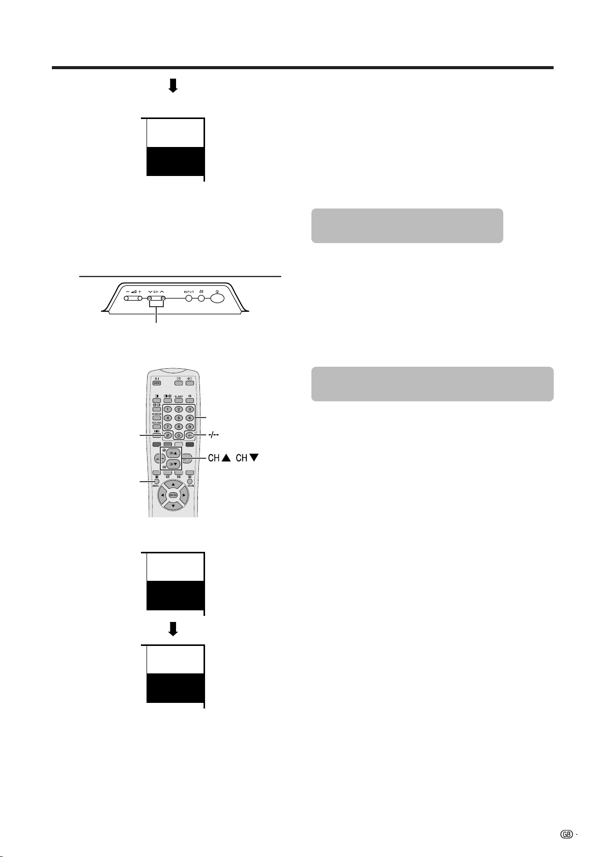
Simple button operations for changing channels … 15
Using Flash back (A) on the remote control unit … 15
Simple button operation for changing
volume/sound …………………………………… 16
Basic adjustment settings ……………………………… 19
AV Input mode menu items ………………………… 19
PC Input mode menu items ………………………… 20
Auto installation ……………………………………… 21
Language setting ………………………………… 21
Country setting …………………………………… 21
Programme auto search ………………………… 22
Auto labelling …………………………………… 22
Auto sorting ……………………………………… 23
Preset download ………………………………… 23
Programme setup……………………………………… 24
Auto search ……………………………………… 24
Manual setting for each channel ……………… 24
Additional channels entry ………………… 25
Fine tuning …………………………………… 25
Colour system ……………………………… 25
Sound system (Broadcasting system) …… 26
Labelling channels ………………………… 26
Skipping channels ………………………… 26
Setting the decoder ………………………… 27
Setting the child lock ……………………… 27
Sort ………………………………………………… 28
Language setting for On-screen Display …………… 29
Picture adjustments …………………………………… 30
Colour temperature ……………………………… 31
Film mode ………………………………………… 31
Black ……………………………………………… 32
Monochrome ……………………………………… 32
I/P Setting ………………………………………… 32
Cool Climate ……………………………………… 33
ENGLISH
Vivid Colour ……………………………………… 33
Sound adjustment …………………………………… 34
Power control ………………………………………… 35
Power control for AV source …………………… 35
Power control for PC source …………………… 37
Using external equipment ……………………………… 38
Watching a decoder image ………………………… 39
Connecting a decoder …………………………… 39
Displaying a programme ………………………… 39
Watching a VCR image ……………………………… 40
Connecting a VCR ……………………………… 40
Displaying a VCR image ………………………… 40
Using AV Link function ……………………………… 41
Watching a DVD image ……………………………… 42
Connecting a DVD player ……………………… 42
Displaying a DVD image ………………………… 42
Enjoying a game console and viewing camcorder
images …………………………………………… 43
Connecting a game console or camcorder …… 43
Displaying an image of the game player and
camcorder …………………………………… 43
Viewing an image from a computer ………………… 44
Connecting a computer ………………………… 44
Displaying an image from a computer ………… 44
Removing the speakers ……………………………… 45
Useful adjustment settings ………………………………46
Image position (AV Input mode only) ……………… 46
Moving the picture on the screen …………………… 47
Auto Sync. adjustment (PC Input mode only) ……… 48
Fine Sync. adjustment (PC Input mode only) ……… 48
Input signal source …………………………………… 49
Colour system setting (AV Input mode only) ……… 50
AV mode ……………………………………………… 50
WIDE mode (for AV Input mode) …………………… 51
WIDE mode (for PC Input mode) …………………… 52
Wide screen signalling (WSS)
(AV Input mode only) …………………………… 53
Picture aspect ratio (AV Input mode only) ………… 53
Selecting Full Mode display (AV Input mode only)… 54
Audio out ……………………………………………… 55
Sleep timer …………………………………………… 55
Password setting for child lock
(AV Input mode only) …………………………… 56
Useful features …………………………………………… 57
Dual screen functions ………………………………… 57
Teletext function ……………………………………… 59
Time display …………………………………………… 61
Appendix ………………………………………………… 62
Troubleshooting ……………………………………… 62
Computer compatibility chart ………………………… 63
RS-232C port specifications ………………………… 64
Connecting pin assignments for SCART …………… 66
Specifications ………………………………………… 67
Dimensional drawings ……………………………………68
1
Page 3

Dear SHARP customer
Thank you for your purchase of the SHARP LCD colour TV product. To ensure safety and many years of troublefree operation of your product, please read the Important Safety Precautions carefully before using this product.
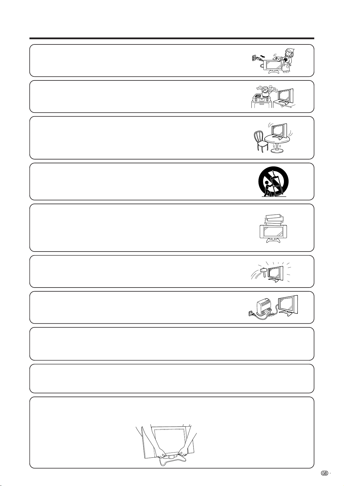
Important Safety Precautions
Electricity is used to perform many useful functions, but it can also cause personal injuries and property
damage if improperly handled. This product has been engineered and manufactured with the highest priority
on safety. However, improper use can result in electric shock and/or fire. In order to prevent potential danger,
please observe the following instructions when installing, operating and cleaning the product. To ensure your
safety and prolong the service life of your LCD colour TV product, please read the following precautions
carefully before using the product.
1. Read instructions—All operating instructions must be read and understood before the product is operated.
2. Keep this manual in a safe place—These safety and operating instructions must be kept in a safe place for future
reference.
3. Observe warnings—All warnings on the product and in the instructions must be observed closely.
4. Follow instructions—All operating instructions must be followed.
5. Attachments—Do not use attachments not recommended by the manufacturer. Use of inadequate attachments
can result in accidents.
6. Power source—This product must operate on a power source specified on the specification label. If you are not
sure of the type of power supply used in your home, consult your dealer or local power company.
7. AC cord protection—The AC cords must be routed properly to prevent people from stepping on them or objects
from resting on them. Check the cords at the plugs and product.
8. Overloading—Do not overload AC outlets or extension cords. Overloading can cause fire or electric shock.
9. Entering of objects and liquids—Never insert an object into the product through vents or openings. High voltage
flows in the product, and inserting an object can cause electric shock and/or short internal parts. For the same
reason, do not spill water or liquid on the product.
10. Servicing—Do not attempt to service the product yourself. Removing covers can expose you to high voltage and
other dangerous conditions. Request a qualified service person to perform servicing.
11. Repair—If any of the following conditions occurs, unplug the AC cord from the AC outlet, and request a qualified
service person to perform repairs.
a. When the AC cord or plug is damaged.
b. When a liquid was spilled on the product or when objects have fallen into the product.
c. When the product has been exposed to rain or water.
d. When the product does not operate properly as described in the operating instructions.
Do not touch the controls other than those described in the operating instructions. Improper adjustment of
controls not described in the instructions can cause damage, which often requires extensive adjustment
work by a qualified technician.
e. When the product has been dropped or damaged.
f. When the product displays an abnormal condition. Any noticeable abnormality in the product indicates that
the product needs servicing.
12. Replacement parts—In case the product needs replacement parts, make sure that the service person uses
replacement parts specified by the manufacturer, or those with the same characteristics and performance as the
original parts. Use of unauthorized parts can result in fire, electric shock and/or other danger.
13. Safety checks—Upon completion of service or repair work, request the service technician to perform safety
checks to ensure that the product is in proper operating condition.
14. Wall or ceiling mounting—When mounting the product on a wall or ceiling, be sure to install the product according
to the method recommended by the manufacturer.
15. Unplug the AC cord from the AC outlet before installing the speakers.
2
Page 4
Important Safety Precautions
• Cleaning—Unplug the AC cord from the AC outlet before cleaning the product.
Use a damp cloth to clean the product. Do not use liquid cleaners or aerosol
cleaners.
• Water and moisture—Do not use the product near water, such as bathtub,
washbasin, kitchen sink and laundry tub, swimming pool and in a wet basement.
• Stand—Do not place the product on an unstable cart, stand, tripod or table. Placing
the product on an unstable base can cause the product to fall, resulting in serious
personal injuries as well as damage to the product. Use only a cart, stand, tripod,
bracket or table recommended by the manufacturer or sold with the product. When
mounting the product on a wall, be sure to follow the manufacturer’s instructions.
Use only the mounting hardware recommended by the manufacturer.
• When relocating the product placed on a cart, it must be moved with utmost care.
Sudden stops, excessive force and uneven floor surface can cause the product to
fall from the cart.
• Ventilation—The vents and other openings in the cabinet are designed for ventilation.
Do not cover or block these vents and openings since insufficient ventilation can
cause overheating and/or shorten the life of the product. Do not place the product
on a bed, sofa, rug or other similar surface, since they can block ventilation openings.
This product is not designed for built-in installation; do not place the product in an
enclosed place such as a bookcase or rack, unless proper ventilation is provided
or the manufacturer’s instructions are followed.
• The LCD panel used in this product is made of glass. Therefore, it can break when
the product is dropped or applied with impact. Be careful not to be injured by
broken glass pieces in case the LCD panel breaks.
• Heat sources—Keep the product away from heat sources such as radiators, heaters,
stoves and other heat- generating products (including amplifiers).
The LCD panel is a very high technology product with 2,949,120 thin film transistors, giving you fine picture
details.
Occasionally, a few non-active pixels may appear on the screen as a fixed point of blue, green or red.
Please note that this does not affect the performance of your product.
Warning:
This is a class A product. In a domestic environment this product may cause radio interference in which
case the user may be required to take adequate measures.
Precautions when transporting the display
When transporting the display, never carry it by holding onto the speakers. Be sure to always carry the
display by two people holding it with two hands-one hand on each side of the display.
3
Page 5
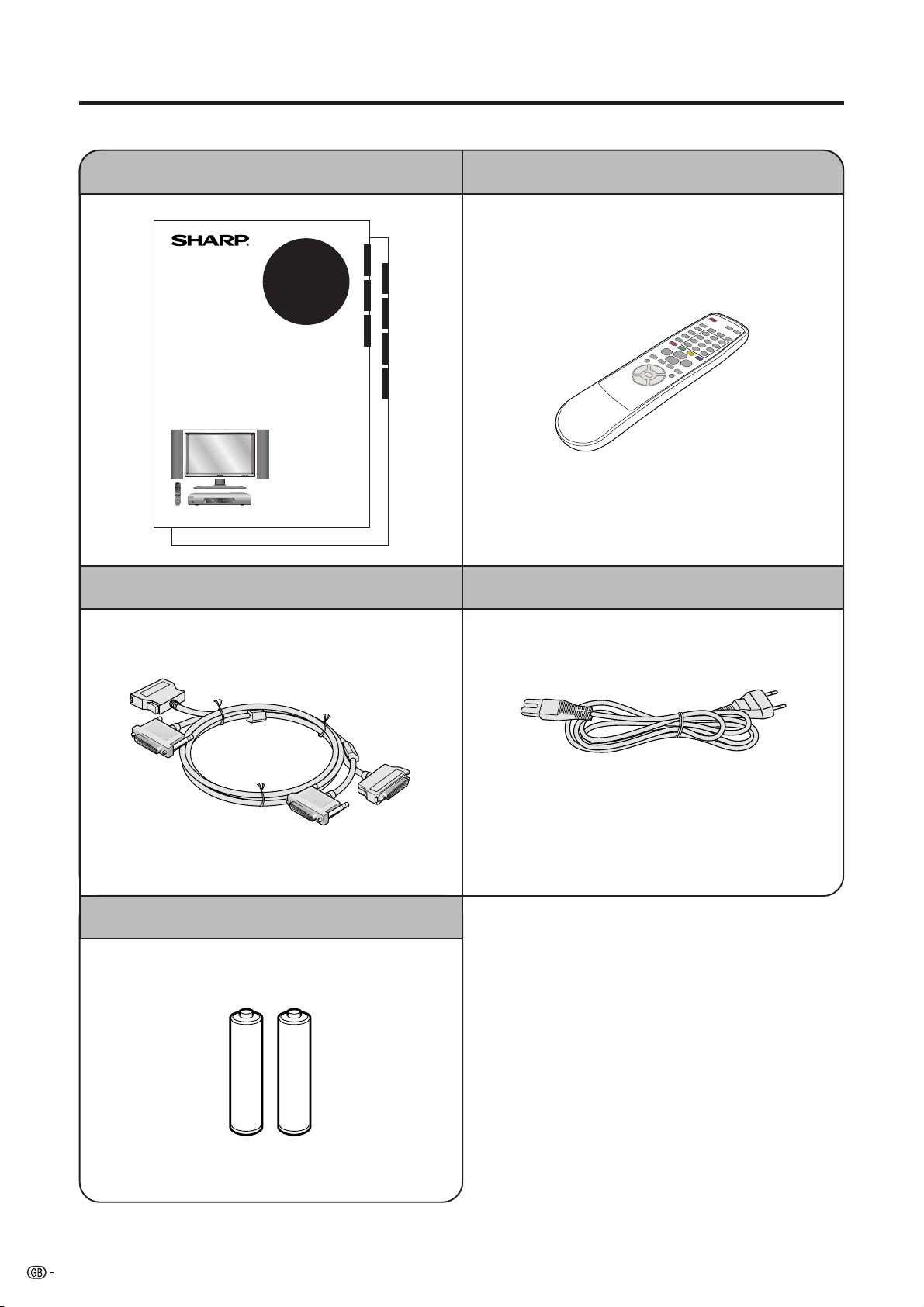
Supplied accessories
Make sure the following accessories are provided with the product.
Operation manual (g2) Remote control unit (g1)
ENGLISHDEUTSCH
LC-30HV2E
ITALIANOESPAÑOL
LCD AV MONITOR
LCD-FARBFERNSEHGERÄT
TÉLÉVISION COULEUR À ÉCRAN
À CRISTAUX LIQUIDES (LCD)
OPERATION MANUAL
BEDIENUNGSANLEITUNG
MODE D’EMPLOI
FRANÇAIS
SVENSKA
NEDERLANDS
System cable (g1) AC cord (g2)
* Product shape varies in some countries.
R-6 (“AA” size, UM/SUM-3) Alkaline battery (g2)
4
Page 6
AC INPUT
110V–240V
DISPLAY INPUT2 DISPLAY INPUT1
AC INPUT
110V–240V
DISPLAY INPUT2 DISPLAY INPUT1
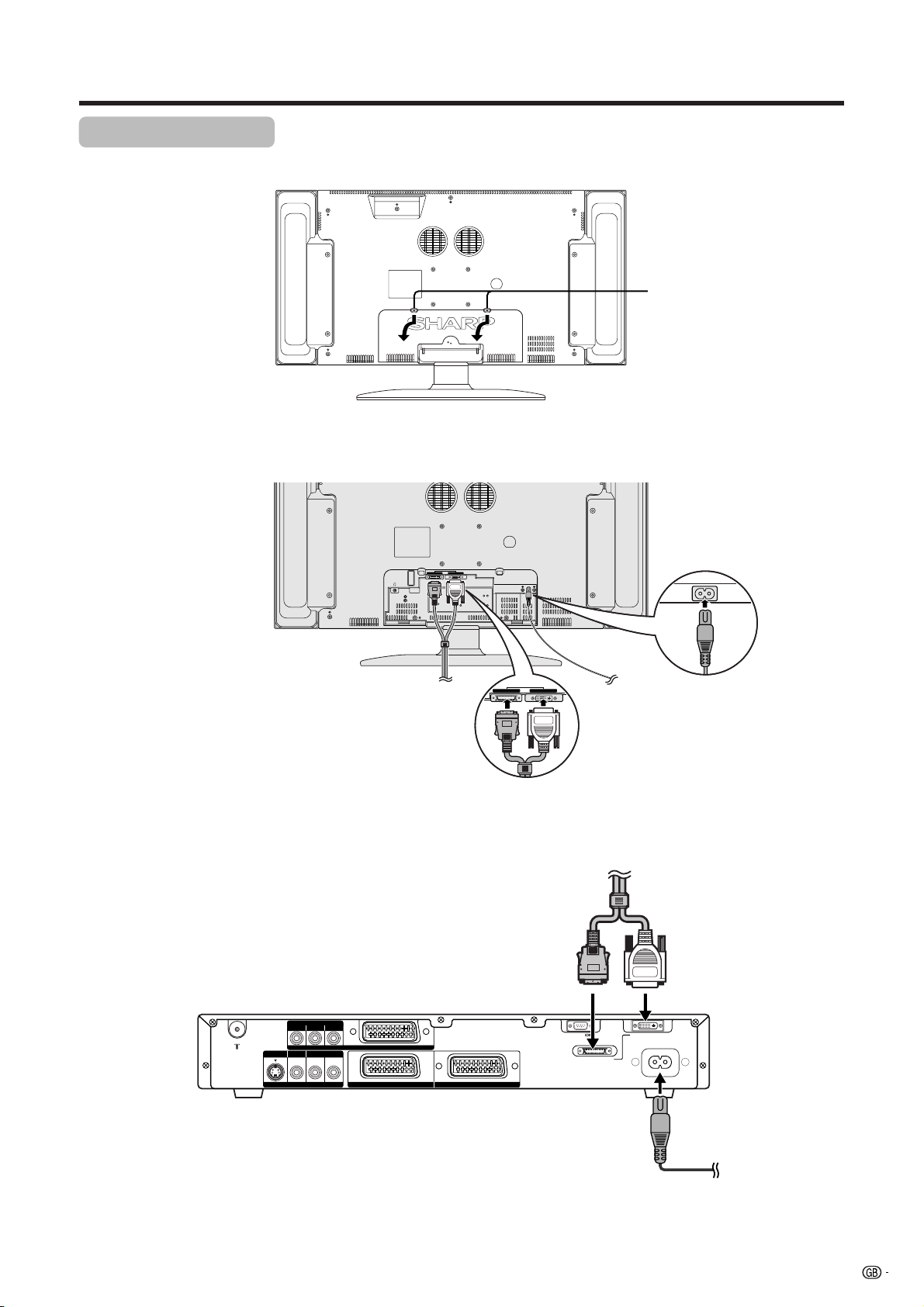
Preparation
Setting the system
Removing the terminal cover
DISPLAY OUTPUT-2 DISPLAY OUTPUT-1
1. Connecting the system cable and the AC cord to the Display
Display (rear view)
AC INPUT
110V–240V
Press down the two
upper hooks to remove
the cover toward you.
(GRAY)
Connect the plug firmly
until the hooks on both
sides click.
System cable
2. Connecting the system cable and the AC cord to the AVC System
(GRAY) (WHITE)
AVC System (rear view)
COMPONENT
PB(CB)
S-VIDEO VIDEO
AV OUTPUT
R - AUDIO - L
PR(CR)Y
INPUT 3
INPUT 2 INPUT 1
RS-232C DISPLAY OUTPUT1
AC cord
(WHITE)
Connect the plug into
the terminal and secure
it by tightning the
thumb screws.
System cable
DISPLAY OUTPUT2
AC INPUT
220–240V
AC cord
L
• TO PREVENT RISK OF ELECTRIC SHOCK, DO NOT TOUCH UN-INSULATED PARTS OF ANY CABLES WITH THE AC
CORD CONNECTED.
5
Page 7
Preparation
Inserting the batteries
If the remote control unit fails to operate the LCD colour TV functions, replace the batteries in the remote control
unit.
1 Open the battery cover. 2 Insert batteries (two R-6 (“AA” size,
UM/SUM-3) Alkaline batteries,
supplied with product).
+
3 Close the battery cover.
_
• Place batteries with their terminals
corresponding to the (e) and (f)
indications in the battery compartment.
L
Improper use of batteries can result in chemical leakage or explosion. Be sure to follow the instructions below.
• Do not use manganese batteries. When you replace the batteries, use alkaline ones.
• Place the batteries with their terminals corresponding to the (e) and (f) indications.
• Do not mix batteries of different types. Different types of batteries have different characteristics.
• Do not mix old and new batteries. Mixing old and new batteries can shorten the life of new batteries or cause
chemical leakage in old batteries.
• Remove batteries as soon as they have worn out. Chemicals that leak from batteries can cause a rash. If you
find any chemical leakage, wipe thoroughly with a cloth.
• The batteries supplied with this product may have a shorter life expectancy due to storage conditions.
• If you will not be using the remote control unit for an extended period of time, remove the batteries from it.
_
+
Using the remote control unit
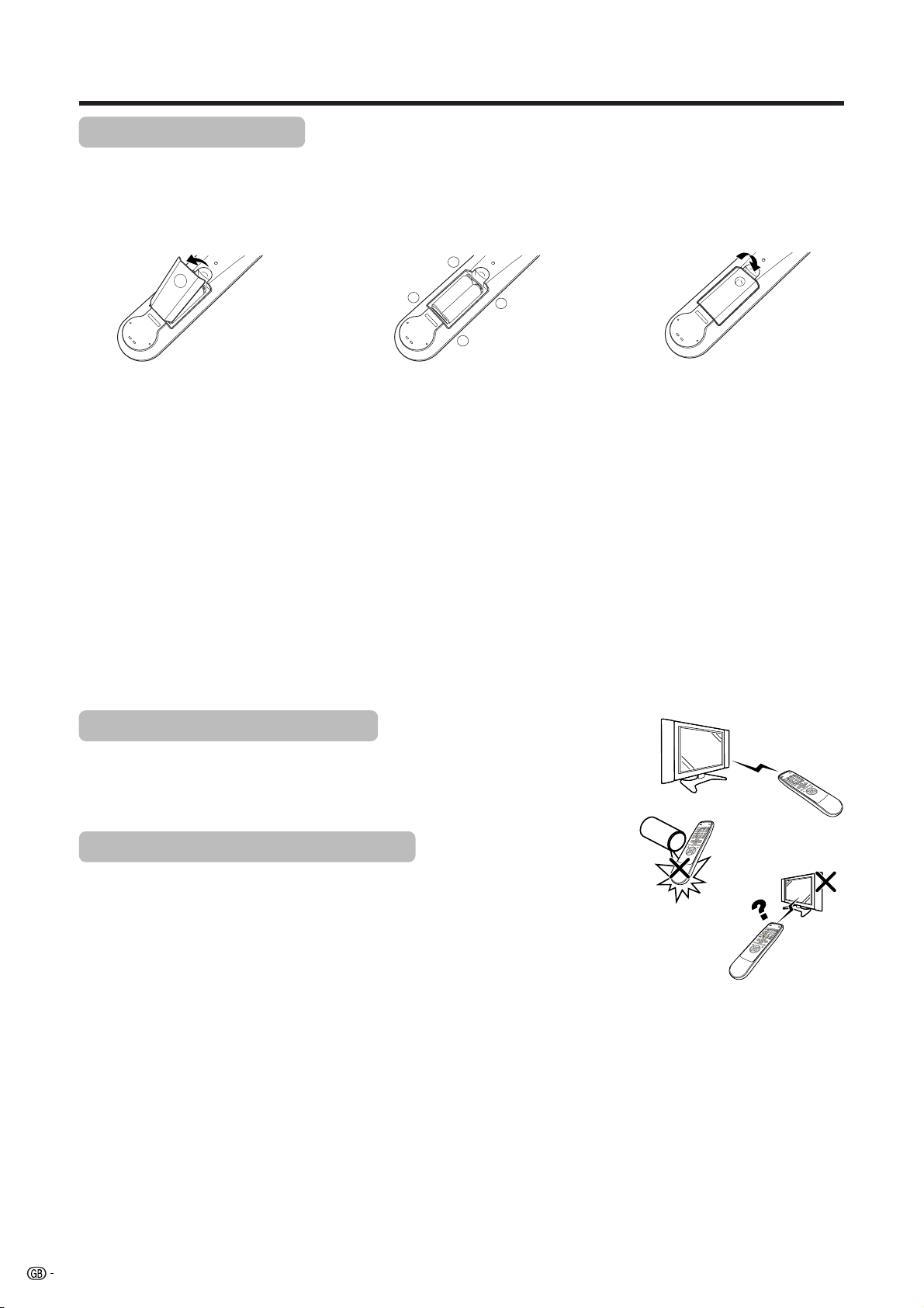
Use the remote control unit by pointing it towards the remote sensor window.
Objects between the remote control unit and sensor window may prevent proper
operation.
Cautions regarding remote control unit
• Do not expose the remote control unit to shock.
In addition, do not expose the remote control unit to liquids, and do not place
in an area with high humidity.
• Do not install or place the remote control unit under direct sunlight.
The heat may cause deformation of the unit.
• The remote control unit may not work properly if the remote sensor window of
the Display is under direct sunlight or strong lighting. In such case, change
the angle of the lighting or Display, or operate the remote control unit closer to
the remote sensor window.
6
Page 8
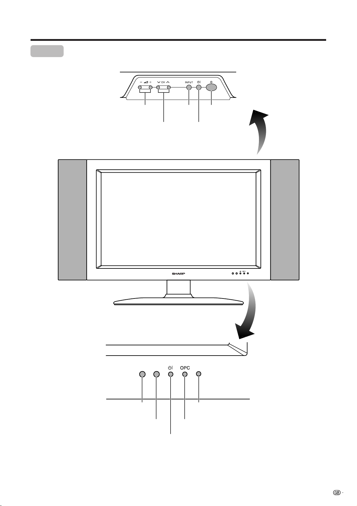
Part names
Display
VOLUME buttons
( il/k )
CHANNEL buttons
(CHs/r)
INPUT
button
STANDBY/ON button
MAIN POWER
button
Remote control sensor
OPC sensor
STANDBY/ON indicator
Remote control sensor indicator
OPC indicator*
*OPC: Optical Picture Control
7
Page 9
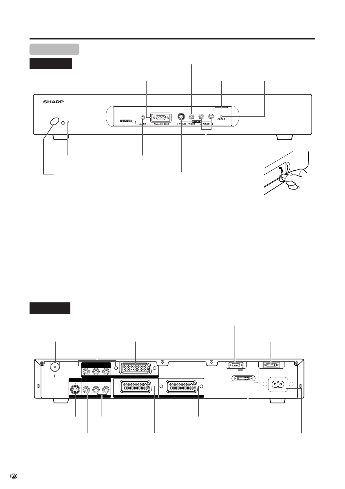
Part names
AVC System
Front view
STANDBY/ON indicator
PC INPUT terminal (ANALOG RGB)
PC INPUT terminal
INPUT 4 terminal (VIDEO)
Door knob
INPUT 4 terminals (AUDIO)
CLEAR button*
(AUDIO)
POWER button
INPUT 4 terminal (S-VIDEO)
(How to open the door)
* If the AVC System is switched on but it does not appear to be operating correctly, it may need resetting. In this
case, press CLEAR on the front of the unit as shown in the diagram. Press CLEAR lightly with the end of a
ballpoint pen or other pointed object.
This will reset the System as shown below.
• AV MODE resets to STANDARD.
• TV channel resets to channel 1.
• Dual screen resets to normal.
• Audio setting initialises.
• SRS resets to OFF.
• Image position is initialised.
A
• Pressing CLEAR will not work if the System is in standby mode (indicator lights red).
• Pressing CLEAR will not delete channel preset or password. See Page 56 for initialising factory preset settings when you
know your password. See Page 70 for initialising factory preset values when you have forgotten your password.
Rear view
ANTENNA INPUT terminal
AV OUTPUT terminal
(S-VIDEO)
8
INPUT 3 terminals
B(CB), PR(CR))
(Y, P
INPUT 3 terminal (SCART)
COMPONENT
PB(CB)
PR(CR)Y
S-VIDEO VIDEO
R - AUDIO - L
AV OUTPUT
INPUT 3
AV OUTPUT terminals
(AUDIO)
AV OUTPUT terminal
(VIDEO)
INPUT 2 INPUT 1
INPUT 1 terminal
(SCART)
INPUT 2 terminal
(SCART)
RS-232C terminal
DISPLAY OUTPUT1 terminal
RS-232C DISPLAY OUTPUT1
DISPLAY OUTPUT2
DISPLAY OUTPUT2 terminal
AC INPUT
220–240V
AC INPUT terminal
Page 10
Part names
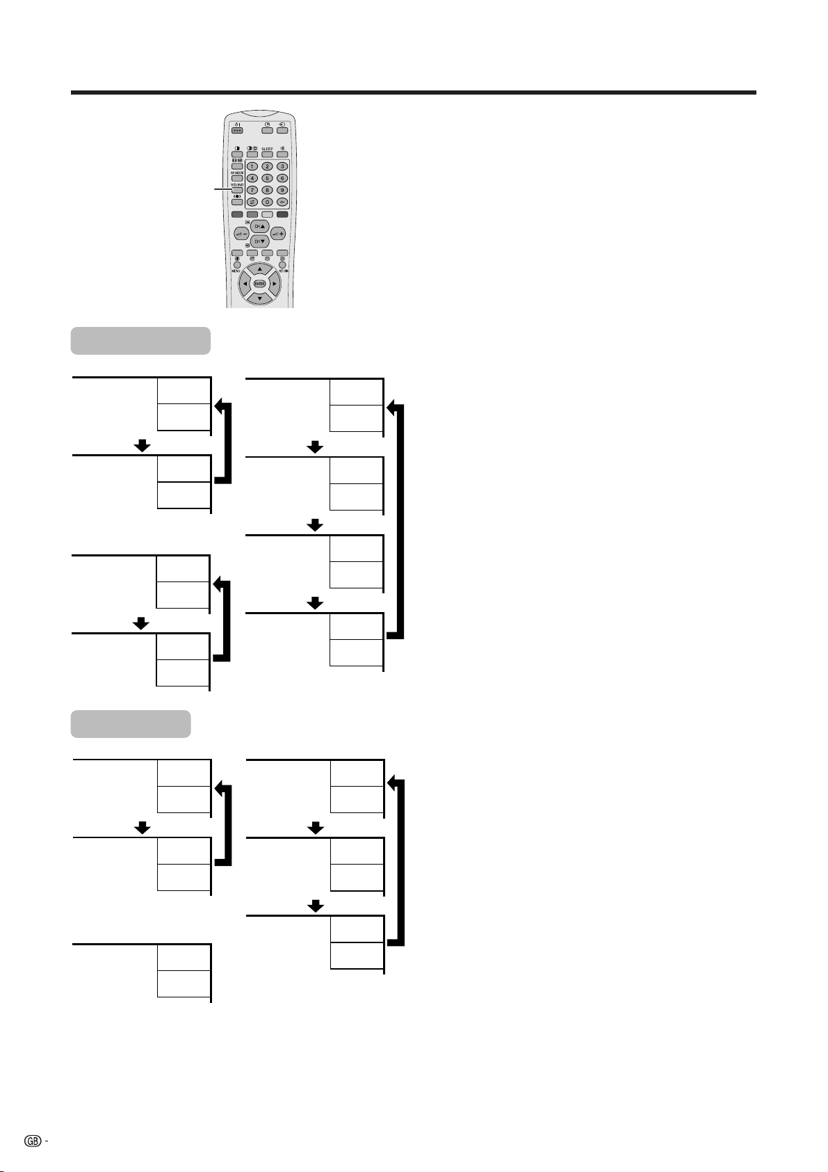
Remote control unit
13
1
2
3
14
15
16
4
5
17
6
7
8
18
19
9
20
10
11
12
21
22
23
24
25
A
• When using the remote control unit, point it
at the Display.
* SRS and the R symbol are trademarks
of SRS Labs, Inc.
SRS technology is incorporated under
license from SRS Labs, Inc.
FOCUS and the R symbol are
trademarks of SRS Labs, Inc. FOCUS
technology is incorporated under license
from SRS Labs, Inc.
1 B (STANDBY/ON)
To switch the power on and off.
2 du (FREEZE/HOLD for TELETEXT)
TV/External input mode: Change the still image mode.
TELETEXT mode: Freeze a multi-page on screen while other
pages are automatically updated. Press d again to return to the
normal image.
3 c (DUAL screen)
Set the dual picture mode. Press c again to return to normal view.
4 fv (WIDE MODE/ T/B/F)
TV/External input mode: Change the wide image mode.
TELETEXT mode: Set the area of magnification. (full/upper half/
lower half)
5 AV MODE
Select a video setting: AV MODE (STANDARD, DYNAMIC, MOVIE,
GAME, USER), PC MODE (STANDARD, USER)
6 SOUND
Select the sound multiplex mode.
7 h (SRS and FOCUS)*
Select SRS and FOCUS Sound System.
8 A (Flash back)
Press to return to the previous channel in normal viewing mode.
Press to return to the previous page in TELETEXT mode.
9 il/ik (VOLUME)
Set the volume.
10 k (Reveal hidden for TELETEXT)
TELETEXT mode: Display hidden characters.
11 j (SUBPAGE for TELETEXT)
TELETEXT mode: Change the picture mode for sub-page selecting.
12 MENU
Display the Menu screen.
13 C (CHANNEL INFORMATION)
Display the channel information and time. (See page 61 for details
on the time display.)
14 b (INPUT SOURCE)
Select an input source. (TV, INPUT 1, INPUT 2, INPUT 3, INPUT 4,
PC)
15 SLEEP
Set the SLEEP TIMER.
16 e (MUTE)
Mute the sound.
17 0 – 9
TV/External input mode: Set the channel.
TELETEXT mode: Set the page.
18 o (Digit for channel select)
Change the digits of the selected TV channel.
19 Colour (RED/GREEN/YELLOW/BLUE)
TELETEXT mode: Select a page.
20 CHa/CHb(w/x )
TV/External input mode: Select the channel.
TELETEXT mode: Set the page.
21 l (TOP Overview for TELETEXT)
TELETEXT mode: Display an index page for CEEFAX/FLOF
information. TOP OVER VIEW for TOP programme.
22 m (TELETEXT)
Select the TELETEXT mode. (all TV image, all TEXT image, TV/TEXT
image)
23 RETURN
MENU mode: Return to the previous menu screen.
24 ENTER
Execute a command.
Return to the initial image position after moving with a/b/c/d.
25 a/b/c/d (Cursor)
Select a desired item on the setting screen.
Move the picture on the screen.
9
Page 11
Watching TV
Simple operations for watching a TV programme
Basic connection
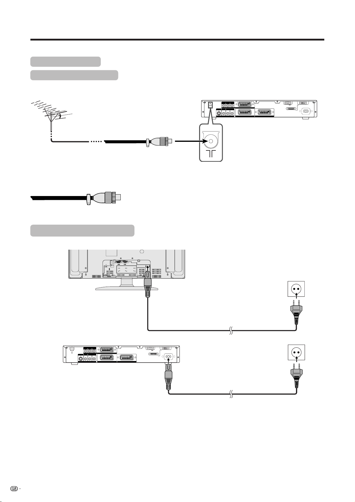
Connecting to an antenna
To enjoy a clearer picture, use an outdoor antenna. The following is a brief explanation of the types of connections
that are used for coaxial cable.
COMPONENT
PB(CB)
Standard DIN45325 plug (IEC169-2)
75-ohm coaxial cable (round
cable) (commercially available)
Antenna cables-commercially available
If your outdoor antenna uses a 75-ohm coaxial cable with a standard DIN45325
plug (IEC 169-2), plug it into the ANTENNA INPUT terminal at the rear of the
AVC System.
S-VIDEO VIDEO
AV OUTPUT
R - AUDIO - L
PR(CR)Y
INPUT 3
INPUT 2 INPUT 1
RS-232C DISPLAY OUTPUT1
DISPLAY OUTPUT2
AC INPUT
220–240V
Connecting to the power outlet
Display (rear view)
DISPLAY INPUT2 DISPLAY INPUT1
AVC System (rear view)
COMPONENT
PB(CB)
PR(CR)Y
INPUT 3
R - AUDIO - L
S-VIDEO VIDEO
AV OUTPUT
INPUT 2 INPUT 1
AC INPUT
110V–240V
RS-232C DISPLAY OUTPUT1
DISPLAY OUTPUT2
Product shape varies
in some countries
AC INPUT
220–240V
Product shape varies
in some countries
A
• Always turn off the main power of Display and AVC System when connecting the AC cords.
• Disconnect the AC cord from the AC outlet, Display and AVC System when the System is not going to be used long
period of time.
10
Page 12
Watching TV
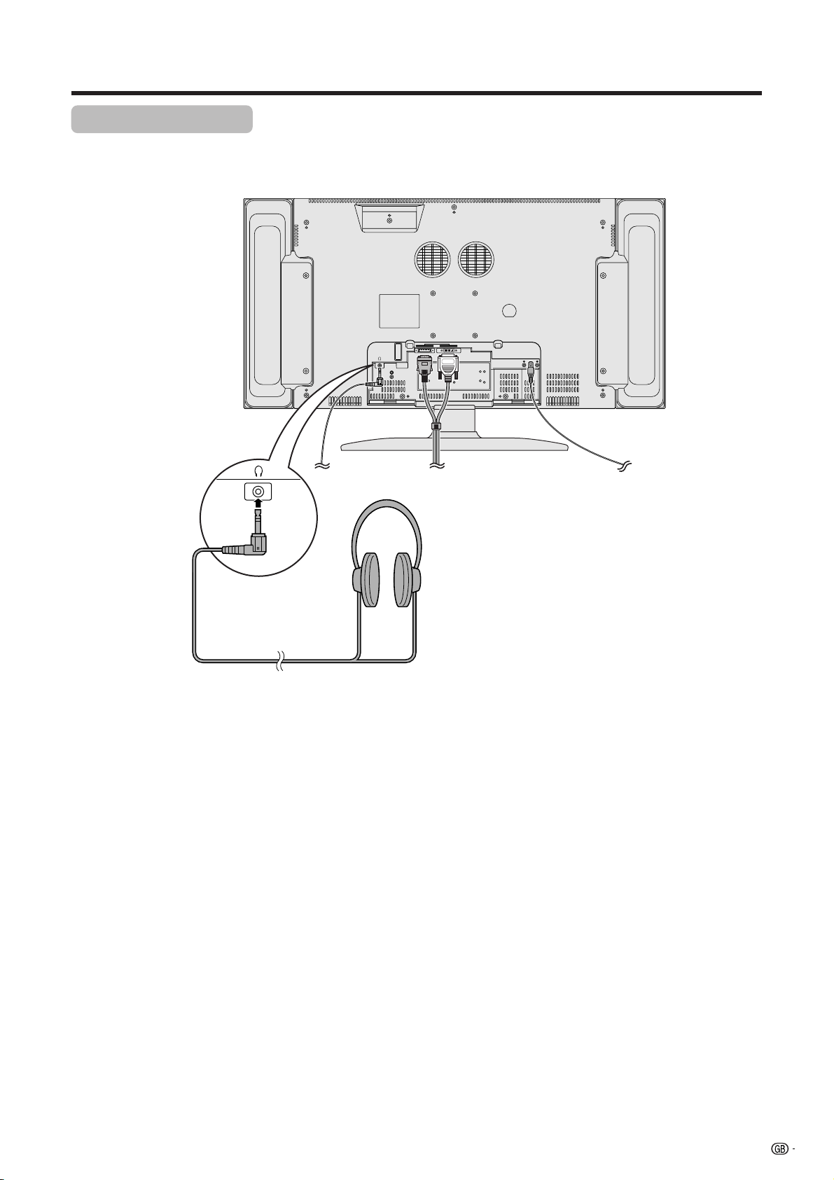
Using Headphones
You can use any pair of headphones (3.5 mm ø mini-jack) to listen to the sound.
Headphones (3.5 mm ø mini-jack)
(commercially available)
DISPLAY INPUT2 DISPLAY INPUT1
AC INPUT
110V–240V
A
• When connecting headphones, the sound from the display speakers is muted.
11
Page 13
Watching TV
Display
STANDBY/ON button
STANDBY/ON indicator
AVC System
STANDBY/ON indicator
POWER
MAIN POWER
Turning on the power
1 Press MAIN POWER on the Display.
• The STANDBY/ON indicator on the Display flashes red.
2 Press POWER on the AVC System.
• The System turns the power on.
• The STANDBY/ON indicator on the Display lights up green and
the one on the AVC System lights up green.
• If the STANDBY/ON indicators still light up red, press B on
the remote control unit or STANDBY/ON button on the Display
to turn the System on.
When turning the AVC System on first
1 Press POWER on the AVC System.
• The STANDBY/ON indicator on the AVC System lights up red.
2 Press MAIN POWER on the Display.
• The System turns the power on.
• The STANDBY/ON indicator on the Display lights up green and
the one on the AVC System lights up green.
• If the STANDBY/ON indicators still light up red, press B on
the remote control unit or STANDBY/ON button on the Display
to turn the System on.
A
•“System” above means the Display and AVC System.
• The initial auto installation starts when the System powers on for the first
time. If the System has been turned on before, the initial auto installation
will not be invoked. See page 21 to try auto installation from the Setup
menu.
Display status indicator
Off
Flashing red
Red
Green
Power off
AVC System does not turn on or its AC cord is disconnected.
The System is in standby mode.
The System turns the power on.
Turning off the power
1 Press B on the remote control unit or STANDBY/ON button
on the Display.
• The System enters standby mode and the image on the screen
disappears.
• Both STANDBY/ON indicators change from green to red.
2 Press POWER on the AVC System.
• The STANDBY/ON indicator on the AVC System turns off and
the one on the Display flashes red.
3 Press MAIN POWER on the Display.
• The STANDBY/ON indicator on the Display turns off after
approximately 5 seconds.
A
• If you are not going to use this System for a long time, be sure to remove
the AC cord from the power outlet.
AVC System status indicator
Off
Red
Green
12
Power off
Only the AVC System is in standby mode or the System is in standby mode.
The System turns the power on.
Page 14
Watching TV
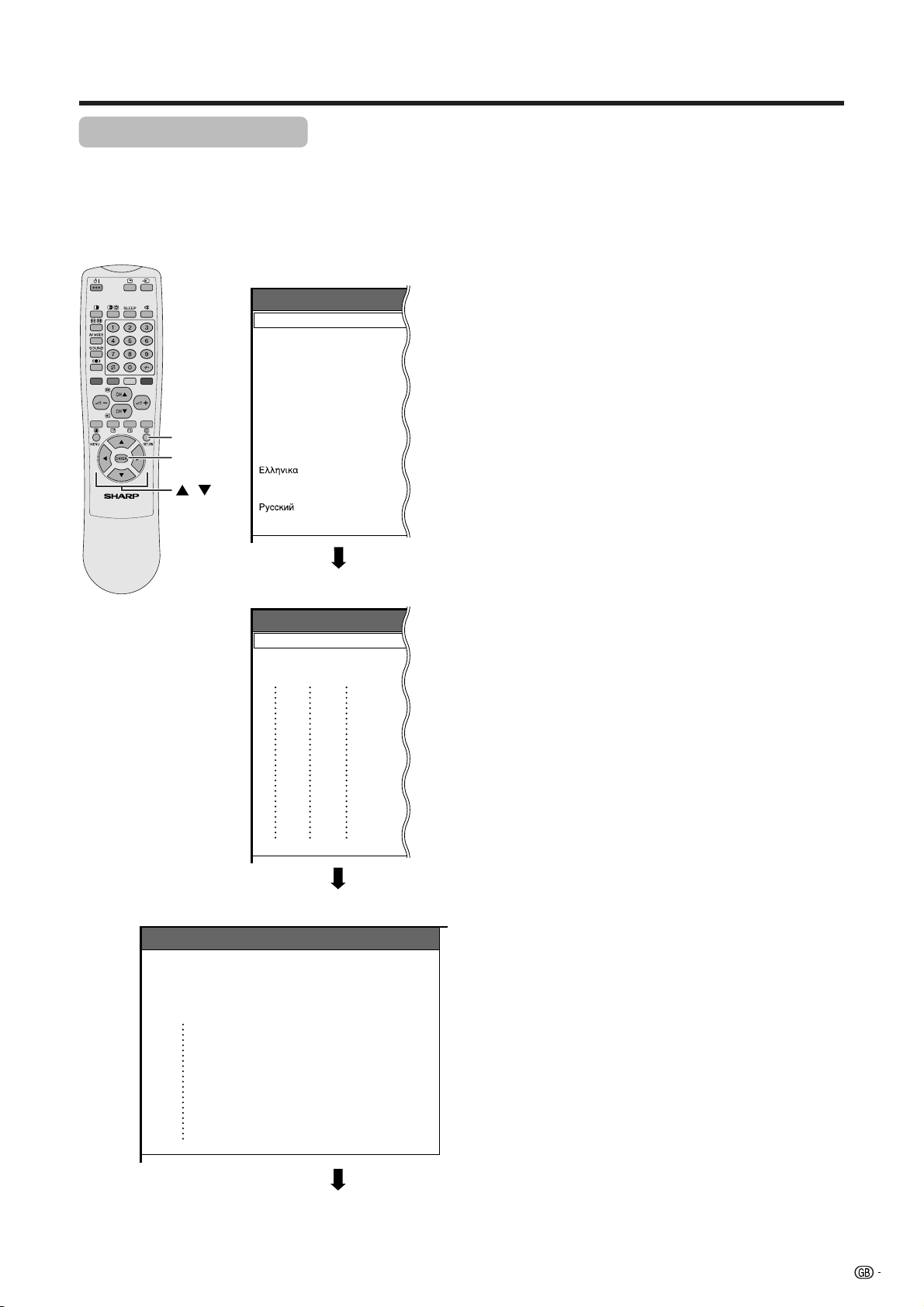
Initial auto installation
When the System powers on for the first time after purchase, the initial auto installation is invoked. You can
automatically set language, country and channels in successive operations.
A
• See page 21 to try Auto installation from the setup menu.
RETURN
ENTER
/
Language menu
Auto Installation - Language
English
Deutsch
Français
Italiano
Español
Nederlands
Svenska
Português
Suomi
Türkçe
Country menu
Auto Installation - Country
Austria
Belgium
Denmark
A
B
DK
B/G
B/G
B/G
1. Setting the on-screen display language
1 Press a/b to select the desired language listed
on the screen.
2 Press ENTER to enter the setting.
2. Setting the country or area
1 Press a/b to select your country or area listed on
the screen.
2 Press ENTER to enter the setting.
• The programme auto search starts at the same time.
A
• Return to the Language menu by pressing RETURN.
Searching TV channels
Auto Installation - Setup “Auto”
1011142.25
010255.25
85.25
03 102.25
04
05
06
07
08
09
148.25
3. Automatic channel searching
Channel auto search makes the System look for all
channels viewable in the set country or area.
A
• If no channel is found, “No programme found. Is antenna
connected properly?” displays. And the auto installation
is finished.
• If you want to try Auto installation again, see page 21.
13
Page 15
Watching TV
4. Automatic channel labelling
Labelling TV channels
Auto Installation - Setup “Auto”
10 142.25
0102SAT.1
PRO7
03 KABEL
04
05
06
07
130.25
08
136.25
09
11 148.25
12 155.25
Sorting TV channels
Auto Installation - Setup “Auto”
10 -----
0102SAT.1
PRO7
03 KABEL
04
05
06
07
08
09
11 -----
12 -----
VOX
QVC
After finding TV channels, the System starts naming
each TV channel found.
A
• The System can only name channels where the channel
labelling information is provided. If channel information is
not provided, the System displays “-----”.
• Cancel the setting by pressing RETURN and the System
automatically returns to the status before programme auto
search.
5. Automatic channel sorting
When channel auto labelling finishes, the System starts
sorting the labelled channels.
A
• Cancel the setting by pressing RETURN. The system
automatically returns to the status before programme auto
search.
Preset download
Sending programme 10 settings.
Programme data sent successfully.
Auto Installation completed.
6. Preset download
When auto sorting finishes, the System automatically
downloads and stores each sorted channel.
• Each time a channel preset download finishes, “Sending
programme 10 settings.” displays. Once all presets have
downloaded, “Programme data sent successfully.”
displays.
• When a VCR is connected via INPUT 2, the System sends
all preset channel information to the VCR. See pages 23,
40 and 41.
14
Page 16
Watching TV
Channel display
SAT.1
1
PAL
B/G
Display
CHs/r
When preset download finishes, your initial auto
installation is completed.
•“Auto Installation completed.” displays. After that, the
screen changes to the auto installation menu.
7. Watching TV
The setup menu disappears and you can watch the
programmes on channel 1.
Simple button operations for
changing channels
aa
Using CH
• Press CH
• Press CH
A
• CHs/r on the Display operates the same as CH
the remote control unit.
Using Flash back (A) on the remote
control unit
bb
a/
bon the remote control unit
aa
bb
aa
a to increase channel number.
aa
b b
b to decrease channel number.
b b
bb
b/
bb
aa
aon
aa
A
MENU
Channel display
SAT.1
12
PAL
B/G
SAT.1
12
MONO
( Displays after 3 secs. )
0–9
Press A to switch the currently tuned channel to the
previously tuned channel.
Press A again to switch back to the currently tuned
channel.
/
Using 0 – 9 on the remote control unit
Select the channels directly by pressing buttons 0 to
9.
a
To select a 1-digit channel (e.g. channel 2):
• Press 2. If “2” is indicated and the picture does not
change, press o to switch over to the 1-digit select
mode and press 2 again.
To select a 2-digit channel (e.g. channel 12):
• Press o to set the 2-digit select mode. Press 1,
followed by 2.
A
• Complete this procedure within 3 seconds, otherwise the
selection will not be made on the 2-digit channel mode.
When viewing Teletext information
View a page directly which is 3-digit page number from
100 to 899 by pressing buttons 0 to 9. With Teletext,
you do not use o. See page 59.
15
Page 17
Watching TV
20
ll
li
ll
kk
k
kk
Display
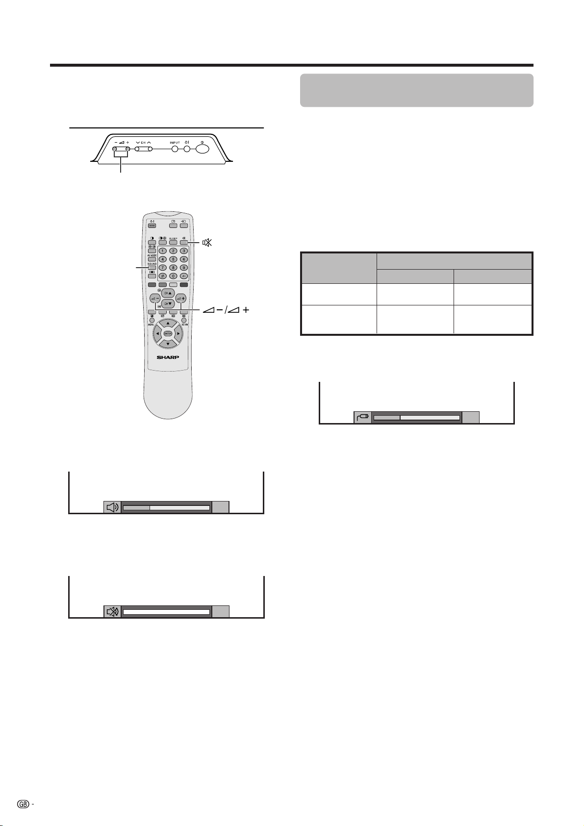
Simple button operation for changing
volume/sound
• To increase the volume, press i
• To decrease the volume, press i
A
•“TV”, “INPUT1”, “INPUT2”, “INPUT3”, “INPUT4” and “PC”
modes can each store volume adjustment values
separately.
Audio status
kk
k.
kk
ll
l.
ll
SOUND
Volume adjustment
20
Output device
Speaker
AV OUTPUT
* When “Audio Out” is set to “Variable”, the indicator on
the screen changes as shown below.
A
• See page 55 for details on the audio out function.
Variable sound
Constant as
specified
Audio out
VariableFixed
Mute
Variable sound
Using e on the remote control unit
e mutes the current sound output.
16
Mute
1 Press e.
•“e” has been displayed on the screen for 8 minutes,
and the sound is silenced.
A
• Within 8 minutes of pressing e, mute can be canceled
by using one of the two methods below.
• Pressing i
A can also cancel the mute.
• Changing channels can also cancel the mute.
• Mute will be canceled after 8 minutes have elapsed.
However, the system will not suddenly output a loud
sound as the volume level is set to 0 automatically.
ff
f/i
ff
ee
e, SOUND, CH
ee
aa
bb
a/CH
b, 0 – 9, b or
aa
bb
2 Within 8 minutes, Press e again to cancel the mute.
• Before 8 minutes, the volume level returns to the
previous setting.
• After 8 minutes, increase the volume level by pressing
ee
i
e.
ee
Page 18
Watching TV
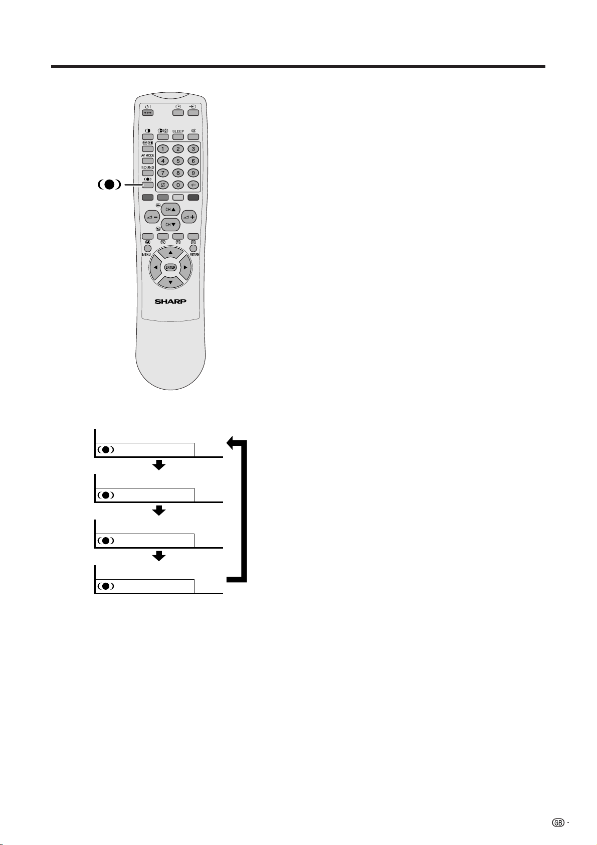
Using h on the remote control unit
h produces SRS and FOCUS effect from the
speakers.
Each time you press h, the mode changes among
SRS, FOCUS, FOCUS e SRS and OFF.
SRS sound options
• SRS (Sound Retrieval System): Creates more a
natural sound retrieving the spatial information from
any stereo recording and restoring the original threedimensional sound field.
• FOCUS: Repositions a sound image from two
speakers to a more optimal listening position or
height without moving them.
• FOCUS e SRS: Produces both SRS and FOCUS
effects.
: OFF
: SRS
: FOCUS
: FOCUS+SRS
• OFF: Outputs the normal sound.
17
Page 19
Watching TV
Using SOUND on the remote control unit
In the NICAM TV broadcasts
SOUND
NICAM broadcasts
Stereo mode
BBC2
NICAM
STEREO
BBC2
MONO
Monaural mode
BBC2
NICAM
MONO
BBC2
MONO
When receiving a stereo signal
Each time you press SOUND, the mode switches
between NICAM STEREO and MONO.
When receiving a bilingual signal
Each time you press SOUND, the mode switches
among NICAM CH A, NICAM CH B, NICAM CH AB
and MONO.
When receiving a monaural signal
Each time you press SOUND, the mode switches
between NICAM MONO and MONO.
Bilingual mode
99
99
99
99
BBC2
99
NICAM
CH A
BBC2
99
NICAM
CH B
BBC2
99
NICAM
CH AB
BBC2
99
MONO
In the TV mode of IGR TV broadcasts
When receiving a stereo signal
Each time you press SOUND, the mode switches
between STEREO and MONO.
When receiving a bilingual signal
Each time you press SOUND, the mode switches
among CH A, CH B and CH AB.
When receiving a monaural signal
When you press SOUND, “MONO” displays.
A
• When no signal is input, the sound mode will display
“MONO”.
•“BBC2” and “99” are tentative network name and channel.
IGR broadcasts
Stereo mode Bilingual mode
BBC2
99
STEREO
BBC2
99
MONO
Monaural mode
BBC2
99
MONO
BBC2
99
CH A
BBC2
99
CH B
BBC2
99
CH AB
18
Page 20
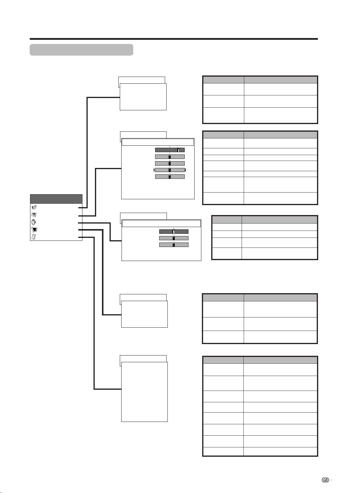
Basic adjustment settings
AV Input mode menu items
List of AV menu items to help you with operations
Page 35–36
Power control
Power Save [Standard]
No Signal off [Disable]
First MENU
MENU
Power control
Picture
Audio
Setup
Option
No Operation off
RETURN
Page 30–33
Picture
DYNAMIC
Contrast
Bright
Colour
Tint
Sharp
Advanced
Reset
RETURN
Page 34
Audio
DYNAMIC
Treble
Bass
Balance
Reset
RETURN
[+30]
[0]
[0]
[0]
[0]
[0]
[0]
[0]
[Disable]
0
–30
–30
–30
–7
–15
–15
Left
+40
+30
+30
+30
+7
Power Save
No Signal off
No Operation off
Contrast
Bright
Colour
Tint
Sharp
Advanced
Reset
+15
+15
Right
MENU
MENU
MENU
Treble
Bass
Balance
Reset
Description
Save power by decreasing picture
brightness.
System automatically shuts down if
no video signal inputs for 15 minutes.
System automatically shuts down if
you do not operate the System for 3
hours.
Description
Adjusts the picture between light and
shade.
Adjusts picture brightness.
Adjusts colour intensity.
Adjusts skin colour to a more natural
tone for all colour system.
Adjusts picture sharpness.
Adjusts “Colour Temp”, “Film Mode”,
“Black”, “Monochrome”, “I/P Setting”,
“Cool Climate” and “Vivid Colour”.
All image adjustment settings return
to the factory preset values.
Description
Adjusts the treble weaker or stronger.
Adjusts the bass weaker or stronger.
Adjusts audio output between left
and right speakers.
All audio adjustment settings return
to the factory preset values.
Page 21–28, 56
Setup
Auto Installation
Programme Setup
Child Lock
RETURN
Page 29, 46, 49, 50, 53–55
Option
Input Select
WSS
4:3 Mode
Full Mode [Mode1]
Position
Audio Out
Colour System
Language
RETURN
[On]
[Panorama]
[Fixed]
[AUTO]
[English]
MENU
Auto Installation
Programme
Setup
Child Lock
MENU
Input Select
WSS
4:3 Mode
Full Mode
Position
Audio Out
Colour System
Language
Description
Runs auto installation again the same
as when the System powers on for
the first time after purchase.
Sets the channel preset.
Sets a password to restrict
operations.
Description
Select the kind of input signal of each input
source.
When wide screen signal bits are present in the
TELETEXT data, you can view information in
wide screen mode.
When you receive a 4:3 or 14:9 mode signal,
select “Normal” or “Panorama” display.
Select Full mode display setting.
Adjusts the horizontal/vertical position of the
image displayed.
Select the type of audio output. You can adjust
volume for the main speaker or audio output.
Select the colour system of an image current
input.
Select the on screen display language.
19
Page 21
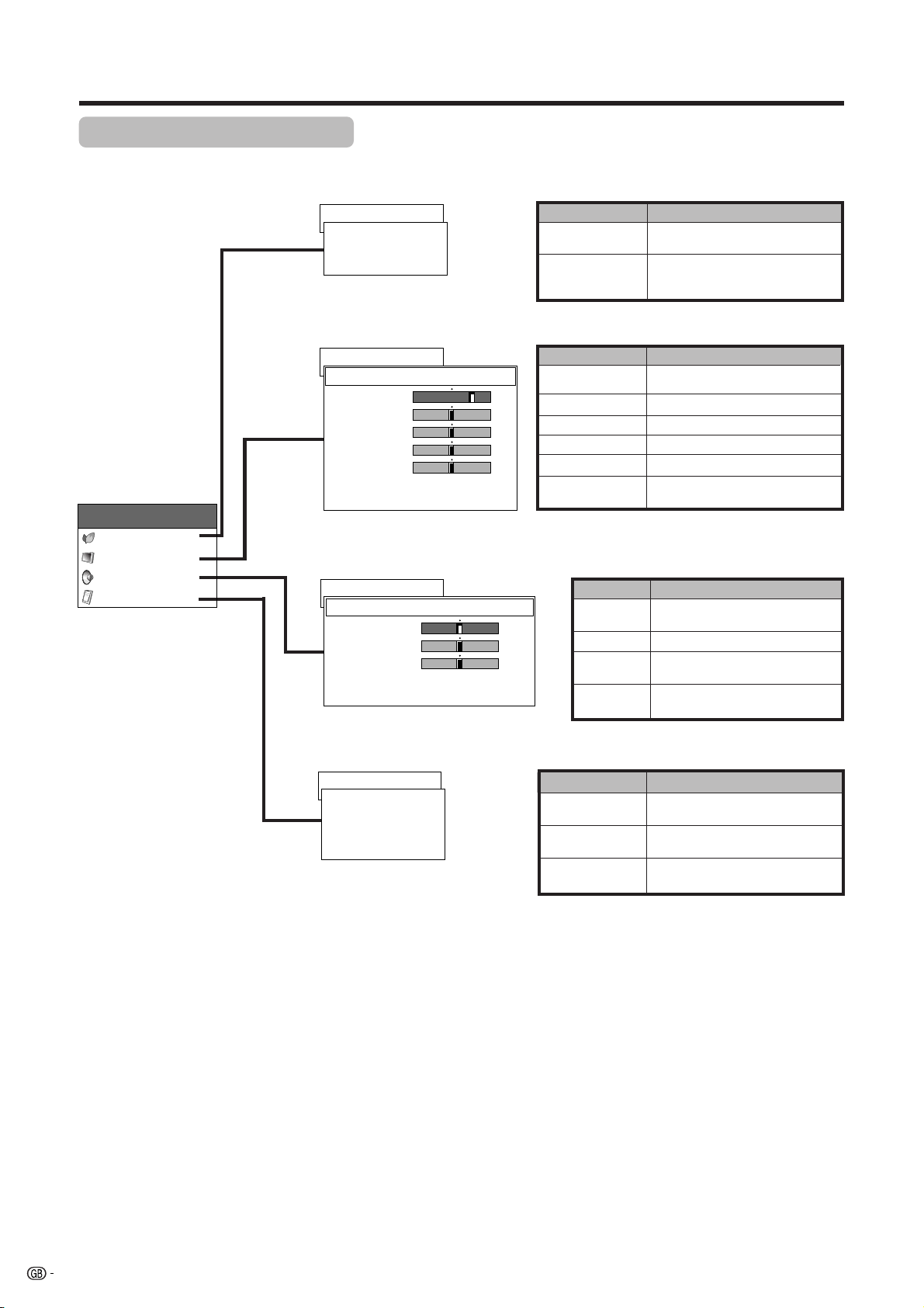
Basic adjustment settings
PC Input mode menu items
List of PC menu items to help you with operations
Page 37
Power Control
Power Save [Standard]
First MENU
MENU
Power Control
Picture
Audio
Option
Power Management
RETURN
Page 30
Picture
USER
Contrast
[+30]
Bright
[0]
Red
[0]
Green
[0]
Blue
[0]
Reset
RETURN
Page 34
Audio
USER
Treble
Bass
Balance
Reset
RETURN
[0]
[0]
[0]
[Off]
0
–30
–30
–30
–30
–15
–15
Left
+40
+30
+30
+30
+30
+15
+15
Right
MENU
Power Save
Power
Management
MENU
Contrast
Bright
Red
Green
Blue
Reset
MENU
Treble
Bass
Balance
Reset
Description
Save power by decreasing picture
brightness.
System automatically shuts down if
you set the time. Select mode 1 or
mode 2.
Description
Adjusts the picture between light and
shade.
Adjusts picture brightness.
Adjusts red colour intensity.
Adjusts green colour intensity.
Adjusts blue colour intensity.
All image adjustment settings return
to the factory preset values.
Description
Adjusts the treble weaker or
stronger.
Adjusts the bass weaker or stronger.
Adjusts audio output between left
and right speakers.
All audio adjustment settings return
to the factory preset values.
Page 48, 55
Option
Auto Sync.
Fine Sync.
Audio Out
RETURN
[Fixed]
MENU
Auto Sync.
Fine Sync.
Audio Out
Description
Provides a clear input image.
Adjusts image “H-Pos.”, “V-Pos.”,
“Clock”, “Phase”.
Select the type of audio output. You can adjust
volume for the main speaker or audio output.
20
Page 22
Basic adjustment settings
Auto installation
You can run auto installation again, even after setting up the preset channels.
Password menu
MENU
Setup
Password
0–9
A
• This menu displays when setting the
password for the child lock. See
page 56.
Setup menu
MENU
ENTER
/
MENU
Setup
Auto Installation
Programme Setup
Child Lock
RETURN
Language menu
Auto Installation - Language
English
Deutsch
Français
Italiano
Español
Nederlands
Svenska
Português
- ---
Language setting
Select from among 12 languages: English, German,
French, Italian, Spanish, Dutch, Swedish, Portuguese,
Greek, Finnish, Russian and Turkish.
1 Press MENU.
2 Press a/b to select “Setup”, and then press
ENTER.
• Password setting menu displays only when the
password for the child lock is set. See page 56.
• Setup menu displays when the password for the child
lock is not set. Skip the step 3.
3 Enter your 4-digit password with 0 – 9 to temporarily
lift the child lock when you set it.
• See page 56 for details on temporarily lifting the child
lock.
4 Press a/b to select “Auto Installation”, and then
press ENTER.
• Language menu displays.
5 Press a/b to select the desired language listed
on the screen, and then press ENTER.
• Country menu displays.
Suomi
Türkçe
Country menu
Auto Installation - Country
Austria
Belgium
Denmark
A
B
DK
B/G
B/G
B/G
Country setting
After setting the language, to use the System you have
to select the country, which sets the colour system for
viewable TV channels.
Setting screen displays.
1 Press a/b to select your country or area listed on
the screen.
2 Press ENTER.
• The country is set and the programme auto search
starts at the same time.
A
• Return to the language menu by pressing RETURN.
21
Page 23

Basic adjustment settings
Searching TV programmes
Auto Installation - Programme Setup “Auto”
010255.25
85.25
03 102.25
Labelling TV channels
Auto Installation - Programme Setup “Auto”
10 222.25
0102SAT.1
85.25
03 102.25
112.25
04
125.25
05
175.25
06
199.25
07
210.25
08
216.00
09
Programme auto search
After setting the country, perform the procedure below
to search TV channels.
A
• Cancel the setting by pressing RETURN and the System
automatically returns the status before programme auto
search.
• If no channels were found, you should check your
antenna connection, and try auto installation again
because it is finished. (See page 10)
• If the country setting has failed, TV channels may not
be found.
Auto labelling
After finding new TV channels, each network name
are searched and displays.
A
• Cancel the setting by pressing RETURN and the System
automatically returns the status before programme auto
search.
Reading broadcasting station names.
22
Page 24

Basic adjustment settings
Sorting TV channels
Auto Installation - Programme Setup “Auto”
10 -----
0102SAT.1
PRO7
03 KABEL
04
05
06
07
08
-----
09
Auto sorting
Automatically sorts TV channels.
A
• Cancel the setting by pressing RETURN and the System
automatically returns to the status before programme auto
search.
• Don’t shut down the System until “Sorts channels.”
displays.
• If the country setting has failed, TV channels may not
be sorted properly.
Sorts channels.
Preset download
Sending programme 10 settings.
Programme data sent successfully.
Auto Installation completed.
Preset download
When auto sorting finishes, the channels are
automatically stored in memory.
• The “10” in “Sending programme 10 settings” indicates
10 channels.
•“Sending programme 10 settings.” displays during each
channel preset download. Once all presets have
downloaded, “Programme data sent successfully.”
displays.
• The System can only send preset channel information to
a VCR when that device is connected via the INPUT 2
terminal.
23
Page 25

Basic adjustment settings
Programme setup
You can run the auto installation procedure again at any time, by accessing the Setup menu, then Programme
Setup. Channels can be turned automatically or manually.
MENU
ENTER
/
Programme Setup “Manual” menu
Programme Setup “Manual”
10
01
02
03
04
05
06
07
08
09
SAT.1
PRO7
KABEL
11
12
13
14
15
16
17
18
19
20
21
22
23
24
25
26
27
28
29
MENU
Setup
Auto Installation
Programme Setup
Child Lock
RETURN
Auto search
You can also automatically search and download TV
channels by performing the procedure below. This is
the same function as from programme auto search to
preset download in auto installation on pages 22 to
23.
1 Press MENU.
2 Press a/b to select “Setup”, and then press
ENTER.
MENU
Setup
Programme Setup
Auto Search
Manual Adjust
Sort
RETURN
3 Press a/b to select “Programme Setup”, and then
press ENTER.
4 Press a/b to select “Auto Search”, and then press
ENTER.
• Programme auto search starts as shown below.
1 Programme auto search
2 Auto labelling
3 Auto sorting
4 Preset download
A
• Return to the previous menu by pressing RETURN before
programme auto search starts.
• See pages 22 to 23 for the details on the programme auto
search.
MENU
Setup
Programme Setup
Auto Search
Manual Adjust
Sort
RETURN
Manual setting for each channel
You can set some channel items manually. They are
Fine (TV frequency), Colour sys., Sound sys., Label
(Network name), Skip, Decoder and Lock (Child Lock).
1 Press MENU.
2 Press a/b to select “Setup”, and then press
ENTER.
30
31
32
33
34
35
36
37
38
39
40
41
42
43
44
45
46
47
48
49
Fine
Colour sys.
Sound sys.
Label
Skip
Decoder
Lock
[NEXT]
179.75MHz
AUTO
B/G
SAT.1
Off
Off
Off
3 Press a/b to select “Programme Setup”, and then
press ENTER.
4 Press a/b to select “Manual Adjust”, and then
press ENTER.
• Programme Setup “Manual” menu displays.
A
• Return to the previous menu by pressing RETURN.
• Exit the menu by pressing MENU.
• When you exit Programme Setup “Manual” menu, preset
download automatically runs if you change information
on that menu.
Please select channel to be edited.
24
Page 26

Basic adjustment settings
Programme Setup “Manual” menu
Programme Setup “Manual”
10
SAT.1
PRO7
KABEL
11
12
13
14
15
16
17
18
19
01
02
03
04
05
06
07
08
09
Please select channel to be edited.
20
21
22
23
24
25
26
27
28
29
30
31
32
33
34
35
36
37
38
39
40
41
42
43
44
45
46
47
48
49
[NEXT]
Fine
Colour sys.
Sound sys.
Label
Skip
Decoder
Lock
179.75MHz
AUTO
B/G
SAT.1
Off
Off
Off
Additional channels entry
On Programme Setup “Manual” menu
1 Press a/b/c/d to select a channel number
(highlighted blue), and then press ENTER.
• Listed channels are black for “Skip” set to “Off” or blue
for “Skip” set to “On” or no channel.
• The selected channel information displays.
2 Press a/b to select “Skip”, and then press ENTER.
• Skip menu displays.
3 Press a/b to set “Skip” to “Off”, and then press
ENTER.
• Channels with “Skip” set to “On” are skipped even if
you select them by using CHa/CHb while watching
the image from the TV.
A
• Return to the previous menu by pressing RETURN.
• Exit the menu by pressing MENU.
Fine tuning menu
Programme Setup “Manual”
01
02
PRO7
03 KABEL
Programme Setup “Manual”
01
02
PRO7
03 KABEL
Colour system menu
Programme Setup “Manual”
01
SAT.1
02
PRO7 PAL
Fine
Fine
Colour sys.
AUTO
PAL-60
SECAM
NTSC 4.43
Fine tuning
On Programme Setup “Manual” menu
196.25 MHzSAT.1
1 Press a/b/c/d to select the channel you want to
edit, and then press ENTER.
• The selected channel information displays.
2 Press a/b to select “Fine”, and then press ENTER.
• Fine tuning bar displays.
3 Press c/d to adjust the frequency, and then press
ENTER.
• Adjust while checking the background picture as a
1 9 6.25 MHzSAT.1
reference.
• Instead of the above, you can also set by directly
entering the frequency number of the channel with 0 –
9.
a
• 179.75 MHz: Press 1 s 7 s 9 s 7 s 5 s ENTER.
• 49.25 MHz: Press 4 s 9 s 2 s 5 s ENTER.
A
• Return to the previous menu by pressing RETURN.
• Exit the menu by pressing MENU.
Colour system
On Programme Setup “Manual” menu
1 Press a/b/c/d to select the channel you want to
edit, and then press ENTER.
• The selected channel information displays.
2 Press a/b to select “Colour sys.”, and then press
ENTER.
• Receivable colour systems are listed.
3 Press a/b to select the optimum colour system,
and then press ENTER.
A
• Return to the previous menu by pressing RETURN.
• Exit the menu by pressing MENU.
25
Page 27

Basic adjustment settings
Sound menu
Programme Setup “Manual”
SAT.1
01
PRO7 D/K
02
Sound sys.
B/G
I
L
L’
Sound system (Broadcasting system)
On Programme Setup “Manual” menu
1 Press a/b/c/d to select the channel you want to
edit, and then press ENTER.
• The selected channel information displays.
2 Press a/b to select “Sound sys.”, and then press
ENTER.
• Receivable sound systems (Broadcasting systems) are
listed.
3 Press a/b to select the optimum sound system,
and then press ENTER.
A
• If you adjust this setting, please check the colour system
information on page 25.
• Return to the previous menu by pressing RETURN.
• Exit the menu by pressing MENU.
Labelling menu
Programme Setup “Manual”
01
SAT.1
02
PRO7
03 KABEL
Skip menu
Programme Setup “Manual”
01
02
PRO7
03 KABEL
Label
KABEL
A
H
O
V
2
9+–
Skip
OffSAT.1
On
Labelling channels
When a TV channel sends its Network Name, the auto
installation detects the information and assigns a name
to it. However, you can change individual channel
G
B
C
D
E
F
CLEAR
I
J
K
L
M
N
P
Q
R
S
T
U
W
X
Y
Z
0
1
NEXT
3
4
5
6
7
8
BACK
END.
names.
On Programme Setup “Manual” menu
1 Press a/b/c/d to select the channel you want to
edit, and then press ENTER.
• The selected channel information displays.
2 Press a/b to select “Label”, and then press
ENTER.
• Alphabet and numbers are listed.
3 Press a/b/c/d to select each character of the
new name for the channel, and then press ENTER.
4 Repeat the above until the name is fully spelt out.
• The name can be 5 characters or less.
A
• Return to the previous menu by pressing RETURN.
• Exit the menu by pressing MENU.
Skipping channels
Channels with “Skip” set to “On” are passed over when
using CHa/CHb even if selected while watching the
image from the TV.
On Programme Setup “Manual” menu
1 Press a/b/c/d to select the channel you want to
edit, and then press ENTER.
• The selected channel information displays.
2 Press a/b to select “Skip”, and then press ENTER.
• Skip menu displays.
3 Press a/b to set “Skip” to “On”, and then press
ENTER.
26
A
• Return to the previous menu by pressing RETURN.
• Exit the menu by pressing MENU.
Page 28

Basic adjustment settings
MENU
ENTER
///
Setting the decoder
When connecting a decoder to the unit, you need
assign the terminal input.
On Programme Setup “Manual” menu
1 Press a/b/c/d to select the channel you want to
edit, and then press ENTER.
• The selected channel information displays.
2 Press a/b to select “Decoder”, and then press
ENTER.
• Terminal inputs information displays.
3 Press a/b to select an INPUT terminal, and then
press ENTER.
A
•“Off” is factory preset value.
• Return to the previous menu by pressing RETURN.
• Exit the menu by pressing MENU.
Decoder menu
Programme Setup “Manual”
01
SAT.1
02
PRO7
03 KABEL
Lock menu
Programme Setup “Manual”
01
02
PRO7
03 KABEL
Decoder
Off
INPUT1
INPUT2
INPUT3
Lock
OffSAT.1
On
Setting the child lock
You can block the viewing of any channel.
On Programme Setup “Manual” menu
1 Press a/b/c/d to select the channel you want to
edit, and then press ENTER.
• The selected channel information displays.
2 Press a/b to select “Lock”, and then press
ENTER.
• Child lock menu displays.
3 Press a/b to set “Lock” to “On”, and then press
ENTER.
A
• Even when this function is switched “On”, it will not work if
a password has not been set. See page 56 for details on
password setting.
• When “Lock” is set to “On” for a channel, “Child Lock Has
Been Activated.” displays , and the image and sound of
the channel is blocked.
• When pressing ENTER while “Child Lock Has Been
Activated.” displays, password input menu will display.
Inputting the correct password lifts the child lock
temporarily until the power is turned off.
• Return to the previous menu by pressing RETURN.
• Exit the menu by pressing MENU.
27
Page 29

Basic adjustment settings
Sort
MENU
MENU
ENTER
///
Setup
Programme Setup
Auto Search
Manual Adjust
Sort
RETURN
Channel positions can be sorted freely.
1 Press MENU.
2 Press a/b to select “Setup”, and then press
ENTER.
3 Press a/b to select “Programme Setup”, and then
press ENTER.
4 Press a/b to select “Sort”, and then press ENTER.
• The channels are listed. Black ones are set “Skip” to
“Off” and blue are set “Skip” to “On”.
5 Press a/b/c/d to select the channel you want to
move, and then press ENTER.
6 Move it to the desired position by pressing a/b/
c/d, and then press ENTER.
7 Repeat the steps 5 and 6 until all desired channels
have sorted.
Sort menus
Programme Setup “Sort”
0102SAT.1
03 KABEL
04
05
06
07
08
09
Please select channel to replace.
10 -----
PRO7
VOX
Press b.
Programme Setup “Sort”
0102PRO7
03 KABEL
04
05
06
07
08
09
Sorts channels.
10 -----
SAT.1
VOX
A
• Return to the previous menu by pressing RETURN.
• Exit the menu by pressing MENU.
Press b.
Programme Setup “Sort”
0102PRO7
03 SAT.1
04
05
06
07
08
09
10 -----
KABEL
VOX
28
Page 30

Basic adjustment settings
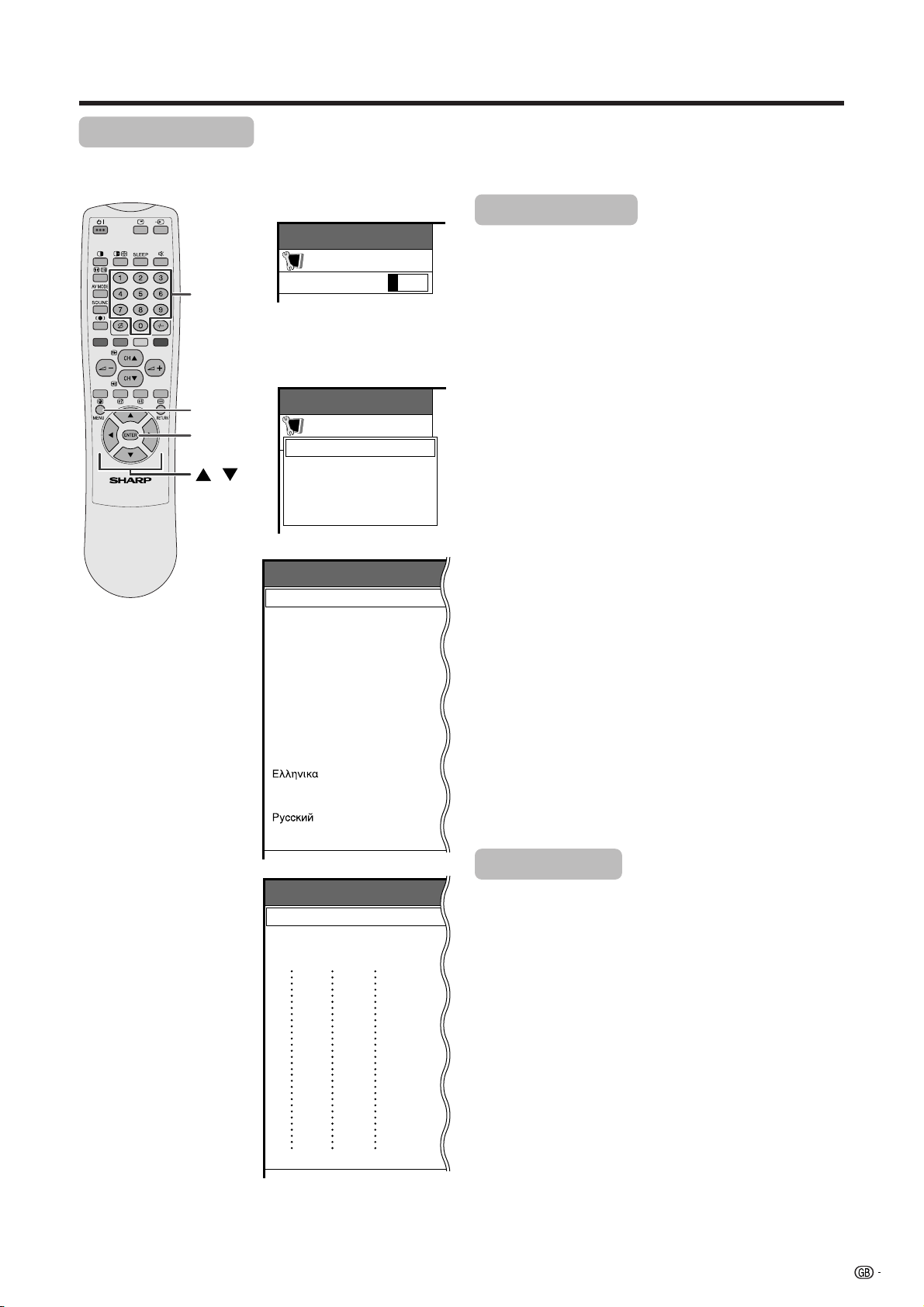
Language Setting for On-screen Display
You can also select a language from option menu. Select from among 12 languages: English, German, French,
Italian, Spanish, Dutch, Swedish, Portuguese, Greek, Finnish, Russian and Turkish.
MENU
ENTER
/
MENU
Option
Input Select
WSS
4:3 Mode
Full Mode [Mode1]
Position
Audio Out
Colour System
Language
RETURN
[On]
[Panorama]
[Fixed]
[Auto]
[English]
MENU
Option
Language
English
Deutsch
Français
Italiano
Español
Nederlands
Svenska
Português
[English]
1 Press MENU.
2 Press a/b to select “Option”, and then press
ENTER.
• Option menu displays.
3 Press a/b to select “Language”, and then press
ENTER.
• Language menu displays.
4 Press a/b to select the desired language listed
on the screen, and then press ENTER.
5 Press MENU to exit the menu.
A
• Return to the previous menu by pressing RETURN.
Suomi
Türkçe
29
Page 31

Basic adjustment settings
Picture adjustments
Adjust the picture to your preference with the following picture settings.
1 Press MENU.
2 Press a/b to select “Picture”, and then press
ENTER.
AV MODE
• Picture menu displays.
3 Press a/b to select a specific adjustment item.
4 Press c/d to adjust the item to your desired
position.
MENU
ENTER
///
5 Press MENU to exit the menu.
A
• When all adjustments set to factory preset values,
1 Press a/b to select “Reset”, and then press ENTER.
2 Press a/b to select “Yes”, and then press ENTER.
• Return to the previous menu by pressing RETURN.
• If you select “STANDARD” with AV MODE on the
remote control unit, these items will display in grey
and not be selectable. See page 50.
Adjustments items for AV source
MENU
DYNAMIC
Contrast
Bright
Colour
Tint
Sharp
Advanced
Reset
RETURN
Selected item
Contrast
Bright
Colour
Picture
[+30]
0
[0]
–30
[0]
–30
[0]
–30
[0]
–7
cbutton
For less contrast
For less brightness
For less colour
intensity
Adjustments items for PC source
AV mode AV mode
MENU
Picture
USER
+40
+30
+30
+30
+7
dbutton
For more contrast
For more brightness
For more colour
intensity
Selected item
Contrast
Bright
Red
Contrast
Bright
Red
Green
Blue
Reset
RETURN
[+30]
[0]
[0]
[0]
[0]
For less contrast
For less brightness
For weaker red
0
–30
–30
–30
–30
cbutton
For more contrast
For more brightness
For stronger red
+40
+30
+30
+30
+30
dbutton
Tint
Sharp
Skin tones become
purplish
For less sharpness
Skin tones become
greenish
For more sharpness
A
• Select “Advanced” and then press ENTER to set “Colour
Temp”, “Film Mode”, “Black”, “Monochrome”, “I/P setting”,
“Cool Climate” or “Vivid Colour”. See pages 31 to 33.
30
Green
Blue
For weaker green
For weaker blue
For stronger green
For stronger blue
Page 32

Basic adjustment settings
AV MODE
MENU
MENU
ENTER
/
Picture
DYNAMIC
Advanced
Colour Temp [High]
High
Mid-High
Mid
Mid-Low
Low
Colour temperature
Adjust the colour temperature to give the best white
image.
1 Press MENU.
2 Press a/b to select “Picture”, and then press
ENTER.
3 Press a/b to select “Advanced”, and then press
ENTER.
4 Press a/b to select “Colour Temp”, and then press
ENTER.
5 Press a/b to select the desired level, and then
press ENTER.
6 Press MENU to exit the menu.
A
• Return to the previous menu by pressing RETURN.
• If you select “STANDARD” with AV MODE on the remote
control unit, this item will display in grey and not be
selectable. See page 50.
MENU
Picture
DYNAMIC
Advanced
Film Mode [On]
Off
On
Selected item
High
Mid-High
Mid
Mid-Low
Low
Description
White with Bluish tone
White with Reddish tone
Film mode
Automatically detects a film-based source (originally
encoded at 24 frames/second), analyses it then
recreates each still film frame for high-definition picture
quality.
1 Press MENU.
2 Press a/b to select “Picture”, and then press
ENTER.
3 Press a/b to select “Advanced”, and then press
ENTER.
4 Press a/b to select “Film Mode”, and then press
ENTER.
5 Press a/b to select “On”, and then press ENTER.
6 Press MENU to exit the menu.
A
• Return to the previous menu by pressing RETURN.
• If you select “STANDARD” with AV MODE on the remote
control unit, this item will display in grey and not be
selectable. See page 50.
• Set the Film Mode to “On” manually to detect a film-based
source (originally encoded 24 frames/second) when input
source has vertical frequency of 50 Hz (e.g. PAL, SECAM
etc.) .
31
Page 33

Basic adjustment settings
AV MODE
MENU
MENU
ENTER
/
Picture
DYNAMIC
Advanced
Black [High]
Off
High
Low
Black
This allows you to select a level for automatic
adjustment of a black areas of the image to suit viewing
conditions.
1 Press MENU.
2 Press a/b to select “Picture”, and then press
ENTER.
3 Press a/b to select “Advanced”, and then press
ENTER.
4 Press a/b to select “Black”, and then press
ENTER.
5 Press a/b to select the desired level, and then
press ENTER.
6 Press MENU to exit the menu.
A
• Return to the previous menu by pressing RETURN.
• If you select “STANDARD” with AV MODE on the remote
control unit, this item will display in grey and not be
selectable. See page 50.
MENU
Interlace
Progressive
MENU
Picture
DYNAMIC
Advanced
Monochrome [On]
Off
On
MENU
Picture
DYNAMIC
Advanced
I/P Setting [Progressive]
Interlace
Progressive
Description
Method of displaying regular TV
broadcasts and video in fine detail
for viewing enjoyment.
Method of displaying still images and
graphics clearly and without
flickering for viewing enjoyment.
Monochrome
For viewing a video in monochrome.
1 Press MENU.
2 Press a/b to select “Picture”, and then press
ENTER.
3 Press a/b to select “Advanced”, and then press
ENTER.
4 Press a/b to select “Monochrome”, and then press
ENTER.
5 Press a/b to select “On”, and then press ENTER.
6 Press MENU to exit the menu.
A
• Return to the previous menu by pressing RETURN.
• If you select “STANDARD” with AV MODE on the remote
control unit, this item will display in grey and not be
selectable. See page 50.
I/P Setting
For viewing a more beautiful (high quality) picture.
1 Press MENU.
2 Press a/b to select “Picture”, and then press
ENTER.
3 Press a/b to select “Advanced”, and then press
ENTER.
4 Press a/b to select “I/P Setting”, and then press
ENTER.
5 Press a/b to select “Interlace” or “Progressive”,
and then press ENTER.
6 Press MENU to exit the menu.
A
• Return to the previous menu by pressing RETURN.
• If you select “STANDARD” with AV MODE on the remote
control unit, this item will display in grey and not be
selectable. See page 50.
• The I/P Setting is enabled only when Film Mode is set to
“Off”.
32
Page 34

Basic adjustment settings
AV MODE
MENU
MENU
ENTER
/
Picture
DYNAMIC
Advanced
Cool Climate [On]
Off
On
Cool Climate
Improves LCD response when viewing fast-moving
images. The effect is greater at low room temperatures
(at or below 15˚C/59˚F).
1 Press MENU.
2 Press a/b to select “Picture”, and then press
ENTER.
3 Press a/b to select “Advanced”, and then press
ENTER.
4 Press a/b to select “Cool Climate”, and then press
ENTER.
5 Press a/b to select “On”, and then press ENTER.
6 Press MENU to exit the menu.
A
• Cool climate may cause image noise. If this occurs turn
the function “Off”.
• Return to the previous menu by pressing RETURN.
• If you select “STANDARD” with AV MODE on the remote
control unit, this item will display in grey and not be
selectable. See page 50.
MENU
Picture
DYNAMIC
Advanced
Vivid Colour [On]
Off
On
Vivid Colour
Sets a more brilliant colour reproduction.
1 Press MENU.
2 Press a/b to select “Picture”, and then press
ENTER.
3 Press a/b to select “Advanced”, and then press
ENTER.
4 Press a/b to select “Vivid Colour”, and then press
ENTER.
5 Press a/b to select “On”, and then press ENTER.
6 Press MENU to exit the menu.
A
• Return to the previous menu by pressing RETURN.
• If you select “STANDARD” with AV MODE on the remote
control unit, this item will display in grey and not be
selectable. See page 50.
33
Page 35

Basic adjustment settings
Sound adjustment
You can adjust the sound quality to your preference with the following settings.
1 Press MENU.
2 Press a/b to select “Audio”, and then press
ENTER.
• Audio menu displays.
AV MODE
3 Press a/b to select a specific adjustment item.
4 Press c/d to adjust the item to your desired
position.
MENU
Adjustments items for AV source
MENU
Audio
USER
Treble
Bass
Balance
Reset
RETURN
[0]
–15
[0]
–15
[0]
Left
ENTER
///
+15
+15
Right
5 Press MENU to exit the menu.
A
• When all adjustments set to factory preset values,
1 Press a/b to select “Reset”, and then press ENTER.
2 Press a/b to select “Yes”, and then press ENTER.
• Return to the previous menu by pressing RETURN.
• If you select “STANDARD” with AV MODE on the
remote control unit, these items will display in grey
and not be selectable. See page 50.
Selected item
Treble
Bass
Balance
cbutton
For weaker treble
For weaker bass
Decrease audio from
the right speaker
dbutton
For stronger treble
For stronger bass
Decrease audio from
the left speaker
34
Page 36

Basic adjustment settings
Power control
Power Control setting allows you to reduce the display brightness to save energy.
Power control for AV source
MENU
ENTER
/
MENU
Power control
Power Save [Save1]
Standard
Save1
Save2
Auto
Power save
When set to “Save1”, “Save2” or “Auto”, power
consumption is reduced by decreasing picture
brightness.
1 Press MENU.
2 Press a/b to select “Power control”, and then
press ENTER.
3 Press a/b to select “Power Save”, and then press
ENTER.
4 Press a/b to select the desired mode, and then
press ENTER.
5 Press MENU to exit the menu.
Selected item
Save1
Save2
AUTO
A
• When setting to “Auto”, make sure no object obstructs
the OPC sensor, which could affect its ability to sense
surrounding light.
•“Standard” is factory preset value.
• Return to the previous menu by pressing RETURN.
• The screen darkens slightly to
conserve power consumption.
• The screen darkens more significantly
to conserve power consumption.
• Screen brightness adjusts according
to the ambient light of the room to
conserve power consumption.
Description
MENU
Power control
No Signal off [Enable]
Disable
Enable
No signal off
When set to “Enable”, the power will automatically shut
down if no signal inputs for 15 minutes.
1 Press MENU.
2 Press a/b to select “Power control”, and then
press ENTER.
3 Press a/b to select “No Signal off”, and then press
ENTER.
4 Press a/b to select “Enable”, and then press
ENTER.
5 Press MENU to exit the menu.
• Five minutes before the power shuts down, a hazard
warning will display every minute.
A
•“Disable” is factory preset value.
• Return to the previous menu by pressing RETURN.
• When a TV programme finishes, and the AVC System
receives signal input, this function may not operate.
35
Page 37

Basic adjustment settings
MENU
ENTER
/
MENU
Power control
No Operation off [Enable]
Disable
Enable
No operation off
When set to “Enable”, the power will automatically shut
down if the signal stays inactive for 3 hours.
1 Press MENU.
2 Press a/b to select “Power control”, and then
press ENTER.
3 Press a/b to select “No Operation off”, and then
press ENTER.
4 Press a/b to select “Enable”, and then press
ENTER.
5 Press MENU to exit the menu.
• Five minutes before the power shuts down, a hazard
warning will display every minute.
A
•“Disable” is factory preset value.
• Return to the previous menu by pressing RETURN.
36
Page 38

Basic adjustment settings
MENU
ENTER
/
MENU
Power Control
Power Save [Save1]
Standard
Save1
Save2
Auto
Power control for PC source
Power control allows you to reduce display brightness
and save energy.
Power save
1 Press MENU.
2 Press a/b to select “Power Control”, and then
press ENTER.
3 Press a/b to select “Power Save”, and then press
ENTER.
4 Press a/b to select the desired mode, and then
press ENTER.
5 Press MENU to exit the menu.
A
•“Standard” is factory preset value.
• Return to the previous menu by pressing RETURN.
MENU
Power Control
Power Management [Off]
Off
Mode1
Mode2
Power management
When set, the power will automatically shut down.
1 Press MENU.
2 Press a/b to select “Power Control”, and then
press ENTER.
3 Press a/b to select “Power Management”, and
then press ENTER.
4 Press a/b to select “Mode1” or “Mode2”, and then
press ENTER.
5 Press MENU to exit the menu.
A
• Return to the previous menu by pressing RETURN.
Selected item
Off
Mode1
• No power management
• Factory preset value.
• If no signal inputs for 8 minutes, the power
shuts down.
• Even if you start using the computer and
the signal inputs again, the System stays
off.
• The System turns on again by pressing
STANDBY/ON button on the Display or B
on the remote control unit. (See page 12.)
Description
Mode2
• If no signal inputs for 8 seconds, the power
shuts down.
• When you start using the computer and the
signal inputs again, the System turns on.
37
Page 39

Using external equipment
You can connect many types of external equipment to your System, like a decoder, VCR, DVD player, computer,
game console and camcorder. To view external source images, select the input source from b on the remote
control unit or INPUT on the Display.
DVD player
S-VIDEO VIDEO
AV OUTPUT
COMPONENT
PB(CB)
R - AUDIO - L
PR(CR)Y
INPUT 3
INPUT 2 INPUT 1
DISPLAY INPUT2 DISPLAY INPUT1
RS-232C DISPLAY OUTPUT1
DISPLAY OUTPUT2
AC INPUT
110V–240V
AVC System
(rear view)
AC INPUT
220–240V
Display
(rear view)
AV Receiver
VCR
Decoder
(Built-in Tuner Amp)
AVC System
(front view)
Computer
L
• To protect all equipment, always turn off the AVC System before connecting to a decoder, VCR, DVD player, computer,
game console, camcorder or other external equipment.
• The S-video signal only outputs when “Input 2” or “Input 3” is selected for “Y/C”, or when from the INPUT 4 terminal (SVIDEO). Only the S-video signal can output from the INPUT 4 terminal (S-VIDEO).
A
• Please refer to the relevant operation manual (DVD player, computer, etc.) carefully before making connections.
Game console/Camcorder
38
Page 40

Using external equipment
Watching a decoder image
Connecting a decoder
You can use the INPUT 1 terminal when connecting a decoder and other audiovisual equipment.
AVC System (rear view)
COMPONENT
PB(CB)
S-VIDEO VIDEO
AV OUTPUT
R - AUDIO - L
PR(CR)Y
INPUT 3
INPUT 2 INPUT 1
SCART cable
(commercially available)
RS-232C DISPLAY OUTPUT1
DISPLAY OUTPUT2
AC INPUT
220–240V
Decoder
MENU
Option
Input Select
Input1 [AV]
AV
RGB
INPUT SOURCE
TV
INPUT1
INPUT2
INPUT3
INPUT4
PC
Displaying a programme
When connecting to the INPUT 1 terminal, select “Input
1” on “Input Select” in the menu to set the correct input
signal type. (See page 49.)
The setting is stored and can be selected on the
“INPUT SOURCE” menu.
To watch a decoder image, select “INPUT1” from the
“INPUT SOURCE” menu using b on the remote
control unit or INPUT on the Display. (See page 49.)
A
• Each time b is pressed, the input source toggles.
• If the decoder image does not come in clearly, you may
need to change the input signal type setting on the “Input
Select” menu.
• It is recommended to connect to the INPUT 1 terminal
when using a decoder for ground wave signal input. If
INPUT 1 signals preset in auto installation or programme
setup, make sure to set “Decoder” to “INPUT1” in the
Programme Setup “Manual” menu. (See page 27.)
• Refer to your decoder operation manual for the signal type.
39
Page 41

Using external equipment
Watching a VCR image
Connecting a VCR
You can use the INPUT 2 terminal when connecting a VCR and other audiovisual equipment.
If your VCR supports TV-VCR advanced “AV Link” systems (see page 41), you can connect the VCR to the
INPUT 2 terminal on the AVC System using the fully-wired SCART cable.
AV Link advanced system
• Download tuning information directly from TV to VCR (Preset download).
• While watching TV, you can record a programme with a one-touch press of the VCR recording button. (WYSIWYR*)
* Refer to your VCR operation manual as some VCRs have an exclusive key for WYSIWYR. See page 41 for details on
“WYSIWYR”.
• When you press the play button on the VCR, the TV automatically turns on from standby and displays a VCR image.
• When you press the system standby button on the VCR, the TV also enters standby mode.
A
• TV-VCR advanced “AV Link” systems may not compatible with some external sources.
• It is recommended to connect to the INPUT 2 terminal when using a decoder for ground wave signal input with a VCR. If
INPUT 2 signals preset in auto installation or programme setup, make sure to set “Decoder” to “INPUT2” in the Programme
Setup “Manual” menu. (See page 27.)
AVC System (rear view)
COMPONENT
PB(CB)
S-VIDEO VIDEO
AV OUTPUT
R - AUDIO - L
PR(CR)Y
INPUT 3
INPUT 2 INPUT 1
RS-232C DISPLAY OUTPUT1
DISPLAY OUTPUT2
AC INPUT
220–240V
SCART cable
(commercially available)
MENU
Option
Input Select
Input2 [AV]
AV
Y/C
INPUT SOURCE
TV
INPUT1
INPUT2
INPUT3
INPUT4
SCART cable
(commercially available)
VCR
Decoder
Displaying a VCR image
When connecting to the INPUT 2 terminal, select “Input
2” on “Input Select” in the menu to set the correct input
signal type. (See page 49.)
The setting is stored and can be selected on the
“INPUT SOURCE” menu.
To watch a VCR image, select “INPUT2” from the
“INPUT SOURCE” menu using b on the remote
control unit or INPUT on the Display. (See page 49.)
A
• Each time b is pressed, the input source toggles.
• If the VCR image does not come in clearly, you may need
to change the input signal type setting on the “Input Select”
menu.
• Refer to your VCR operation manual for the signal type.
40
PC
Page 42

Using external equipment
Using AV Link function
This System incorporates four typical AV Link functions for smooth connections between AVC System and other
audiovisual equipment.
A
• Only works when the audiovisual equipment is connected to the INPUT 2 terminal on the AVC System with AV Link via a
fully wired SCART.
One Touch Play
While the System is in standby mode, it automatically
turns on and plays back the image from the audiovisual
source (e.g. VCR, DVD).
System Standby
When the connected audiovisual equipment (e.g. VCR,
DVD) enters standby mode, so does the System.
WYSIWYR (What You See Is What You
Record)
When the remote control unit of the connected VCR
has the WYSIWYR button, you can automatically start
recording by pressing the WYSIWYR button.
Preset Download
Automatically transfer the channel preset information
from the tuner on the System to the one on the
connected audiovisual equipment (e.g. VCR) via the
INPUT 2 terminal.
A
• Refer to operation manuals of each external equipment
for the details.
AVC System (rear view)
COMPONENT
PB(CB)
PR(CR)Y
INPUT 3
R - AUDIO - L
S-VIDEO VIDEO
AV OUTPUT
INPUT 2 INPUT 1
SCART cable
(commercially available)
RS-232C DISPLAY OUTPUT1
DISPLAY OUTPUT2
VCR
AC INPUT
220–240V
41
Page 43

Using external equipment
Watching a DVD image
Connecting a DVD player
You can use the INPUT 3 terminal when connecting to a DVD player and other audiovisual equipment.
AVC System (rear view)
COMPONENT
PB(CB)
PR(CR)Y
R - AUDIO - L
INPUT 3
S-VIDEO VIDEO
AV OUTPUT
SCART cable
(commercially available)
INPUT 2 INPUT 1
RS-232C DISPLAY OUTPUT1
DISPLAY OUTPUT2
AC INPUT
220–240V
When using component cable,
select “COMPONENT” for “Input
Select” in the menu.
Component cable (commercially available)
MENU
Option
Input Select
Input3 [COMPONENT]
AV
Y/C
RGB
COMPONENT
Displaying a DVD image
When connecting to the INPUT 3 terminal, select “Input
3” on “Input Select” in the menu to set the correct input
signal type. (See page 49.)
The setting is stored and can be selected on the
“INPUT SOURCE” menu.
To watch a DVD image, select “INPUT3” from “INPUT
SOURCE” menu using b on the remote control unit
or INPUT on the Display. (See page 49.)
INPUT SOURCE
TV
INPUT1
INPUT2
INPUT3
A
• Each time b is pressed, the input source toggles.
• If the DVD image does not come in clearly, you may need
to change the input signal type setting on the “Input Select”
menu.
• Refer to your DVD player operation manual for the signal
type.
INPUT4
DVD player
42
PC
Page 44

Using external equipment
Enjoying a game console and viewing camcorder images
Connecting a game console or camcorder
A game console, camcorder and some other audiovisual equipment are conveniently connected using the
INPUT 4 terminals.
A
• The S-video terminal has priority over the video terminals.
AVC System (front view)
Composite video cables
(commercially available)
S-video cable
(commercially available)
INPUT SOURCE
TV
INPUT1
INPUT2
INPUT3
INPUT4
PC
Game console/Camcorder
Displaying an image of the game player and
camcorder
When connecting to the INPUT 4 terminals, select
“INPUT4”.
You only need to select the input source on the “INPUT
SOURCE” menu.
To connect a game console or view a camcorder, select
“INPUT4” from the “INPUT SOURCE” menu using b
on the remote control unit or INPUT on the Display.
(See page 49.)
A
• Each time b is pressed, the input source toggles.
43
Page 45

Using external equipment
Viewing an image from a computer
Connecting a computer
Use the PC terminals to connect a computer.
A
• The PC input terminals are DDC1/2B-compatible.
• Refer to page 63 for a list of computer signals compatible with the System.
AVC System (front view)
RGB cable
(commercially available)
Signal names for 15-pin mini D-sub connecter
5
4 321
10
9
15
141312
6
7
8
11
Pin No. Signal name Pin No. Signal name Pin No. Signal name
1 R 6 GND (Ground) q Not connected
2 G 7 GND (Ground) w SDA
3 B 8 GND (Ground) e HD
4 Not connected 9 +5V r VD
5 CSYNC 0 GND (Ground) t SCL
A
• Macintosh adaptor may be required for use for some Macintosh computers.
INPUT SOURCE
TV
INPUT1
INPUT2
INPUT3
INPUT4
PC
ø 3.5 mm stereo minijack cable
(commercially available)
Displaying an image from a computer
When connecting to a computer, the correct input
signal type is automatically detected. (See page 49.)
If the computer image does not come in clearly, you
may need to set the Auto Sync. adjustment on the “Auto
Sync.” in the menu. (See page 48.)
You only need to select the input source on the “INPUT
SOURCE” menu.
To view an image from a computer, select “PC” from
the “INPUT SOURCE” menu using b on the remote
control unit or INPUT on the Display. (See page 49.)
Computer
44
A
• Each time b is pressed, the input source toggles.
Page 46

Using external equipment
Removing the speakers
This unit has detachable type speakers.
You can detach the system speakers when using external amplifier/speakers.
Before attaching/detaching speakers
• Before performing work make sure to turn off the System.
• Before performing work spread cushioning over a flat surface to lay the Display on. This will prevent it from
being damaged.
123
Unfasten the screws used to
secure the speakers in place.
L
• The speaker terminals on the Display is only for the attached speakers. Do not connect any third party plug or speaker to
the terminal.
• Insert the speaker plug completely into the terminal.
• Do not handle or move the display by the speakers.
A
• Perform the same steps for both left and right speakers.
• To attach the speakers, perform the above steps in reverse order.
Take hold of the speaker and
slowly slide it sideways.
(The speaker plug is still
inserted, so make sure not to
pull the speaker too far.)
Speaker
plug
Remove the speaker plug from
the terminal on the Display.
(Do not remove the plug by
pulling the cord.)
Now the speaker can be
detached from the display.
45
Page 47

Useful adjustment settings
Image position (AV Input mode only)
For adjusting a picture’s horizontal and vertical
position.
1 Press MENU.
2 Press a/b to select “Option”, and then press
ENTER.
MENU
MENU
Position
H-Pos.
V-Pos.
Reset
RETURN
Option
3 Press a/b to select “Position”, and then press
ENTER.
ENTER
4 Press a/b to select “H-Pos.” or “V-Pos.”.
///
5 Press c/d to adjust the item to your desired
position.
6 Press MENU to exit the menu.
A
• For resetting all adjustment items set to the factory preset
values,
1 Press a/b to select “Reset”, and then press ENTER.
2 Press a/b to select “Yes”, and then press ENTER.
• Return to the previous menu by pressing RETURN.
[0]
–15
[0]
–30
+15
+30
• Adjustments are stored separately according to input
source.
• You can easily move the image position as shown on page
47, but when the power is switched off the image will return
to the previously memorised position.
46
Selected item
H-Pos.
V-Pos.
Description
Centres the image by moving it to the left or
right.
Centres the image by moving it up or down.
Page 48
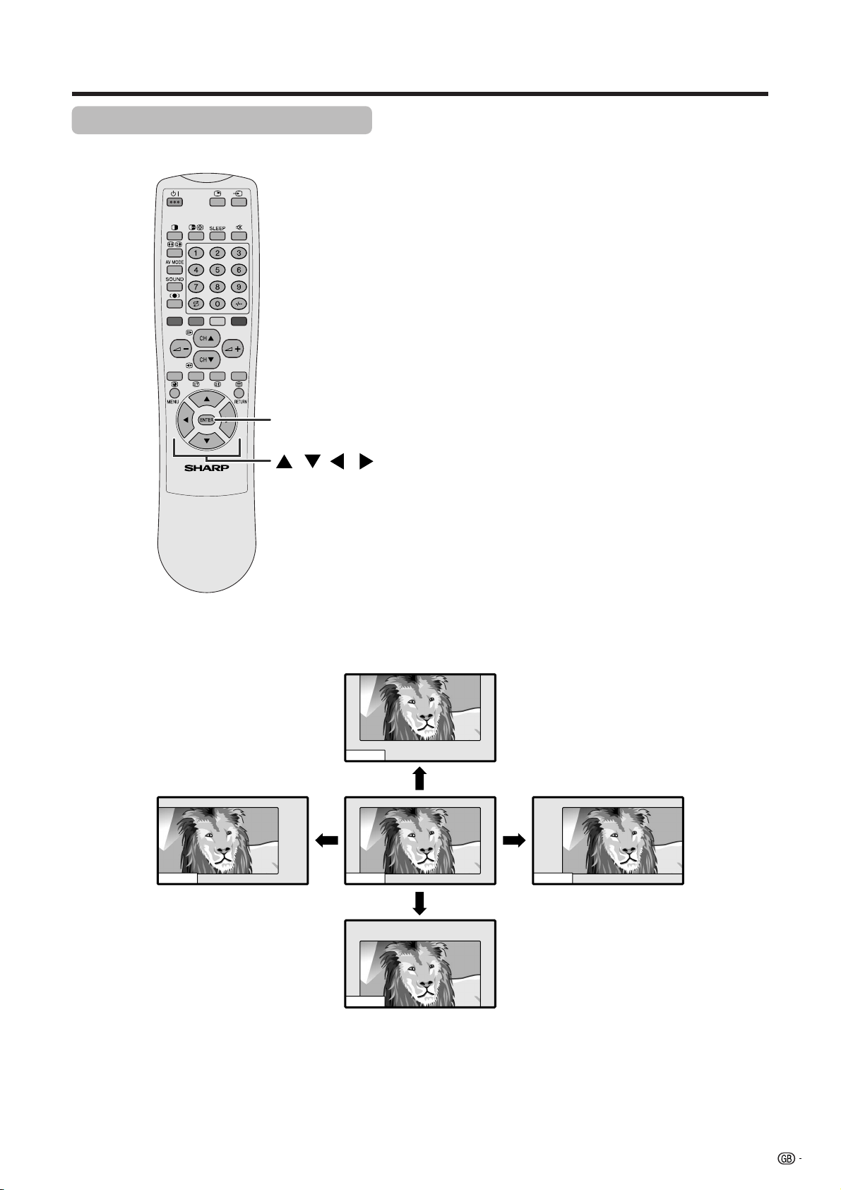
Basic adjustment settings
Moving the picture on the screen
You can move the picture around on the screen.
ENTER
///
Press a/b/c/d to move an image on the screen to
the desired position. Press ENTER to return to the initial
image position.
A
• While pressing a/ b/c/d, an on-screen image,
“Adjusting Position” displays to the desired position.
• This setting cannot be stored. Once the System shuts
down or enters standby mode, the setting is erased. To
move the picture around the screen again, you must
perform the above procedure again.
• The image position setting using the steps on page 46
can be stored. Select either according to your objectives.
•“TV”, “INPUT1”, “INPUT2”, “INPUT3”, “INPUT4” and “PC”
modes can each adjust the image position setting on this
page. The same for WIDE modes.
• An on-screen image from a PC source cannot be moved
around.
• Even when the image fills the screen, its position can be
adjusted with this function.
47
Page 49

Useful adjustment settings
MENU
MENU
ENTER
///
Auto Sync.
Adjusting the image 32%
Option
Auto Sync.
Fine Sync.
Audio Out
RETURN
Auto Sync. adjustment (PC Input
mode only)
For automatically adjusting the computer image.
1 Press MENU.
2 Press a/b to select “Option”, and then press
ENTER.
3 Press a/b to select “Auto Sync.”, and then press
ENTER.
• Auto Sync. starts and “Adjusting the image” displays.
[Fixed]
A
• Return to the previous menu by pressing RETURN.
• When Auto Sync. is successful, “Auto Sync completed
successfully” displays. If not, Auto Sync. failed.
• Auto Sync. may fail even if “Auto Sync completed
successfully” displays.
• Auto Sync. is likely to succeed when an input PC image
has wide vertical stripes (ex. pattern with high contrast
stripes, or cross-hatched).
It may fail when an input PC image is solid (low contrast).
• Be sure to connect the computer to the AVC System and
switch it on before starting Auto Sync.
Selected item
H-Pos.
V-Pos.
Clock
Phase
MENU
Option
Fine Sync.
–90
H-Pos.
V-Pos.
Clock
Phase
Reset
RETURN
[0]
–60
[0]
–90
[0]
[0]
–20
Description
Centres the image by moving it to the left or
right.
Centres the image by moving it to the up or
down.
Adjusts the clock frequency.
Adjusts the clock phase.
+90
+60
+90
+20
Fine Sync. adjustment (PC Input
mode only)
Ordinarily you can easily adjust the picture as
necessary to change image position using Auto Sync.
In some cases, however, manual adjustment is needed
to optimise the image.
1 Press MENU.
2 Press a/b to select “Option”, and then press
ENTER.
3 Press a/b to select “Fine Sync.”, and then press
ENTER.
4 Press a/b to select the specific adjustment item.
5 Press c/d to adjust the item to your desired
position.
6 Press MENU to exit the menu.
A
• When all adjustments set to factory preset values,
1 Press a/b to select “Reset”, and then press ENTER.
2 Press a/b to select “Yes”, and then press ENTER.
• Return to the previous menu by pressing RETURN.
48
Page 50

Useful adjustment settings
MENU
ENTER
/
Input 1 signal menu
MENU
Option
Input Select
Input1 [AV]
AV
RGB
Input 2 signal menu
MENU
Option
Input Select
Input2 [AV]
AV
Y/C
Input 3 signal menu
MENU
Option
Input Select
Input3 [COMPONENT]
AV
Y/C
RGB
COMPONENT
Input signal source
Input signal setting
For setting the signal type of external equipment.
1 Press MENU.
2 Press a/b to select “Option”, and then press
ENTER.
3 Press a/b to select “Input Select”, and then press
ENTER.
4 Press a/b to select an input source you want to
set, and then press ENTER.
5 Press a/b to select a signal type, and then press
ENTER.
• If the selected signal type is incorrect, an image does
not display or no colour image displays.
6 Press MENU to exit the menu.
A
• Return to the previous menu by pressing RETURN.
• The System automatically sets input signals from “INPUT4”
and “PC”.
• If no (colour) image displays, try to change the other
signal type.
• Check the operation manual of the external equipment
for the signal type.
INPUT SOURCE
TV
INPUT1
INPUT2
INPUT3
INPUT4
PC
Input selection
Can use for selecting the input source.
1 Press b on the remote control unit or INPUT on
the Display.
• INPUT SOURCE menu displays.
2 Hold down b on the remote control unit or INPUT
on the Display to select the input source.
• An image from the selected source automatically
displays.
• You can also select the input source by pressing a/
b.
A
• When there are no external sources connected to those
terminals, “INPUT3” (COMPONENT) or “INPUT4” will
display in grey and not be selectable.
• Return to the previous menu by pressing RETURN.
49
Page 51

Useful adjustment settings
AV MODE
Colour system setting (AV Input
mode only)
You can change the colour system to one that is
compatible with the image on the screen.
MENU
Option
Colour System [PAL]
AUTO
MENU
ENTER
/
Mode selection for the INPUT 1 to 4
terminal and TV
AV MODE: STANDARD
AV MODE: DYNAMIC
AV MODE: MOVIE
PAL
PAL-60
SECAM
NTSC 3.58
NTSC 4.43
1 Press MENU.
2 Press a/b to select “Option”, and then press
ENTER.
3 Press a/b to select “Colour System”, and then
press ENTER.
4 Press a/b to select a compatible video signal
system of your equipment, and then press ENTER.
5 Press MENU to exit the menu.
A
• Factory preset value is “AUTO”.
• If “AUTO” is selected, colour systems for each channel
are automatically set. If an image does not display clearly,
select another colour system (e.g. PAL, NTSC 4.43).
• Return to the previous menu by pressing RETURN.
AV mode
AV mode gives you five viewing options to choose from
to best match the System environment, which can vary
due to factors like room-brightness, type of programme
watched or the type of image input from external
equipment.
1 Press AV MODE.
• Present AV mode displays.
2 Press AV MODE again before the mode displayed
on the screen disappears.
• The mode changes as shown left.
AV MODE: GAME
AV MODE: USER
Mode selection for the PC terminal
AV MODE: STANDARD
AV MODE: USER
Selected item
STANDARD
DYNAMIC
MOVIE
GAME
USER
Description
For a highly defined image in a normally
bright room
For a clear-cut image emphasising high
contrast for sports viewing
For a movie
Lowers image brightness for easier viewing.
Allows the user to customise settings as
desired. You can set the mode for each
input source.
50
Page 52

Useful adjustment settings
WIDE mode (for AV Input mode)
WIDE MODE
Normal
Full 14:9
Zoom 14:9
Panorama
Full
Cinema 16:9
Cinema 14:9
/
4:3 Mode set to “Normal” 4:3 Mode set to “Panorama”
Manual Selection
1 Press f.
• The WIDE MODE menu displays.
• The menu lists the wide mode options selectable for
the type of video signal currently received.
2 Press f or a/b while the WIDE MODE menu
displays on the screen.
• As you toggle down the options, each is immediately
reflected on the Display. No need to press ENTER.
Auto Selection
If you set “WSS” and “4:3 Mode” in the Option menu
on page 53, the optimum WIDE mode is automatically
chosen for every broadcast containing the WSS
information.
“WSS” menu
To enable Auto Selection, set “WSS” in the Option menu
to “On”. (See page 53.)
“4:3 Mode” menu
To set the type of the wide screen, select “Normal” or
“Panorama” in the 4:3 Mode menu. (See page 53.)
A
• If the broadcast signal contains no WSS information, Auto
Selection will not function even when the WSS option is
enabled.
Selected item
Normal
Full 14:9
Zoom 14:9
Panorama
Full
Cinema 16:9
Cinema 14:9
Normal Full 14:9
Description
For 4:3 “standard” pictures. A side bar appears on each side.
For 14:9 squeeze pictures. A thin side bar appears on each side.
For 14:9 letterbox pictures. A thin side bar appears on each side, and you may also see bars on
the top and bottom with some programmes.
In this mode the picture is progressively stretched toward each side of the screen.
For 16:9 squeeze pictures. There are two display settings to choose from. (See page 54.)
For 16:9 letterbox pictures. Bars may appear on the top and bottom with some programmes.
For 14:9 letterbox pictures. Bars may appear on the top and bottom with some programmes.
Zoom 14:9
Panorama
FullCinema 16:9Cinema 14:9
51
Page 53

Useful adjustment settings
a
/
WIDE mode (for PC Input mode)
WIDE MODE
Normal
Full
1 Press f.
• The WIDE MODE menu displays.
Dot by Dot
2 Press f or a/b to select an item while the WIDE
MODE menu displays on the screen.
• Items you can selelect from the menu list are shown
below.
Normal Full Dot by Dot
Input signal
640g480
800g600
Input signal
1024g768
1280g768
A
• Selectable items may vary with signal input type.
• What is “Dot by Dot”?
• This function detects the resolution of the signal from a computer and displays an image with the same number of
pixels, dot by dot.
• When an XGA (1024g768) signal is input, selecting “Normal” enables “Dot by Dot” display.
• When a XGA WIDE (1280g768) signal is input, selecting “Dot by Dot (W)” enables “Dot by Dot” display.
Image size varies with
signal input.
(Above is example.)
Normal
Ex. 1024g768
Image with same number
of pixels as input
resolution.
Select either “Normal” or “Full” when 1024g768 signal
is input.
Image fully fills the screen. Image with same number
Full Dot by Dot (W)
Ex. 1024g768
Image fully fills the screen.
of pixels as input
resolution.
(Above is example.)
Ex. 1024g768
For XGA WIDE mode,
select when 1280g768
signal is input.
52
Page 54

Useful adjustment settings
MENU
ENTER
/
MENU
Option
WSS [On]
Off
On
Wide screen signalling (WSS) (AV
Input mode only)
WSS allows a television to switch automatically among
the different screen formats.
1 Press MENU.
2 Press a/b to select “Option”, and then press
ENTER.
3 Press a/b to select “WSS”, and then press
ENTER.
4 Press a/b to select “Off” or “On”, and then press
ENTER.
5 Press MENU to exit the menu.
A
• Return to the previous menu by pressing RETURN.
• Try to set WIDE mode if an image does not switch to the
correct screen format. When the broadcast signal contains
no WSS information, the function will not work even if
enabled. See page 51.
Picture aspect ratio (AV Input mode
only)
WSS signal 4:3 screen
4:3 mode “Normal”
MENU
Option
4:3 Mode [Normal]
Normal
Panorama
4:3 mode “Panorama”
Allows you to select the aspect ratio of a video signal
for standard 4:3 or full screen images.
1 Press MENU.
2 Press a/b to select “Option”, and then press
ENTER.
3 Press a/b to select “4:3 Mode”, and then press
ENTER.
4 Press a/b to select “Normal” or “Panorama”, and
then press ENTER.
5 Press MENU to exit the menu.
A
• Return to the previous menu by pressing RETURN.
• Try to set WIDE mode if an image does not switch to the
correct screen format. When the broadcast signal contains
no WSS information, the function will not work even if
enabled. See page 51.
Selected item
Normal
Panorama
Normal range keeping 4:3 or 16:9 aspect
ratio
Wide image without side bars
Description
53
Page 55

Useful adjustment settings
Selecting Full Mode display (AV Input
mode only)
MENU
ENTER
/
MENU
Option
Full Mode [Mode1]
Mode1
Mode2
Select the display type in Full Mode.
1 Press MENU.
2 Press a/b to select “Option”, and then press
ENTER.
3 Press a/b to select “Full Mode”, and then press
ENTER.
4 Press a/b to select “Mode1” or “Mode2”, and then
press ENTER.
5 Press MENU to exit the menu.
A
• Return to the previous menu by pressing RETURN.
Selected item
Mode1
Mode2
Projects 16:9 squeeze image evenly over
entire screen.
Displays a 16:9 squeeze image without
distortion.
However, black bands appear at the top
and bottom.
Description
Full Mode screen
Full mode “Mode1”
Full mode “Mode2”
54
Page 56

Useful adjustment settings
Audio out
Allows you to select what controls the audio output.
SLEEP
MENU
ENTER
/
MENU
Option
Audio Out [Variable]
Fixed
Variable
1 Press MENU.
2 Press a/b to select “Option”, and then press
ENTER.
3 Press a/b to select “Audio Out”, and then press
ENTER.
4 Press a/b to select “Fixed” or “Variable”, and then
press ENTER.
5 Press MENU to exit the menu.
A
• Return to the previous menu by pressing RETURN.
Selected item
Fixed
Variable
• Sound via speakers is adjusted with
il/k on the remote control unit or the
Display.
• Sound via the AV OUTPUT terminal is not
adjustable and constantly outputs.
• Sound via the AV OUTPUT terminal is
adjusted with il/k on the remote
control unit or the Display.
• Sound via speakers is muted.
Description
Sleep Timer: Remain 120
Sleep timer
Allows you to set a time when the TV automatically
switches to standby.
1 Press SLEEP.
• Remaining time displays when sleep timer has been
set.
2 Each time you press SLEEP, the remaining time
switches as shown below.
• When the time has been set, countdown automatically
starts.
• Five minutes before the preset of time expires, the
remaining time displays each minute.
30 60 90
0
A
• Select “0” by pressing SLEEP to cancel the sleep timer.
120
(minutes)
55
Page 57

Useful adjustment settings
MENU
0–9
Child Lock
Password
MENU
ENTER
/
Setup
New Password
Reconfirm
– –––
––––
Password setting for child lock (AV
Input mode only)
Allows you to use a password to protect certain settings
from being accidentally changed.
Setting a password
1 Press MENU.
2 Press a/b to select “Setup”, and then press
ENTER.
3 Press a/b to select “Child Lock”, and then press
ENTER.
4 Press a/b to select “Password”, and then press
ENTER.
5 Enter the 4-digit number as a password using 0 –
9.
6 Enter the same 4-digit number as in step 5 to
confirm.
•“The new password is registered.” displays.
7 Press MENU to exit the menu.
A
• Return to the previous menu by pressing RETURN
• To view a locked channel (Lock setting in Programme
Setup “Manual” is set to “On”), you must enter a password.
(See page 27.) When you select a locked channel, a
password prompt message pops up. Press ENTER to
display the password input window.
MENU
Setup
Child Lock
PasswordClear
No
Yes
Clearing the password
Allows you to clear your password.
1 Press MENU.
2 Press a/b to select “Setup”, and then press
ENTER.
• Password input menu displays.
3 Enter your 4-digit password with 0 – 9, and then
press ENTER.
• Setup menu displays.
4 Press a/b to select “Child Lock”, and then press
ENTER.
5 Press a/b to select “PasswordClear”, and then
press ENTER.
6 Press a/b to select “Ye s”, and the press ENTER.
• Your password is cleared.
7 Press MENU to exit the menu.
A
• Return to the previous menu by pressing RETURN.
• As a precautionary measure, make a note of your
password and keep it in a familiar place. If you lose or
forget your password, initialise the System to return
all settings except for the TV channel settings to factory
preset values. (See page 70.)
56
Page 58

Useful features
Dual screen functions
Allows you to display two pictures on the screen at one time.
Dual screen
z
You can display two same-sized pictures except when
inputting from a PC INPUT terminal.
1 Press c.
• Dual screen displays and a selected input source
image displays.
z
2 Press c/d to set either screen to be active.
•“z” displays on the active screen, which has sound
output.
3 Press b to select another input source on the
/
active screen.
• A selected image displays.
4 Press c to exit dual screen.
A
• This function does not work under the following input
conditions:
1PC INPUT mode,
2Two pictures from the same source (e.g. INPUT 1 and
INPUT 1),
3Images from a high frequency signal source,
4Two pictures with different vertical frequency (e.g. PAL
and PAL-60).
• When this function is not available, “No dual screen display
available.” will display.
57
Page 59

Useful features
ENTER
Picture and still image
You can display two same-sized pictures – one moving
and one still – when inputting from an AV source.
1 Press d.
• A moving image displays on the left screen and a still
image displays on the right screen. The still image is
one frame captured from a moving image at the
moment you press d.
2 Update the still image by pressing ENTER.
• Each time you press ENTER, the image on the right
screen updates.
3 Press d to exit still image.
A
• This function does not work under the following input
conditions:
1PC INPUT mode,
2Images from a high frequency signal source.
• When this function is not available, “No still image display
available.” will display.
• The still image automatically goes out after eight minutes.
58
FREEZE
Page 60

Useful features
Teletext function
What is Teletext?
Teletext broadcasts pages of information and entertainment to specially equipped television sets. Your System
receives Teletext signals broadcast by a TV network, and decodes them into graphical format for viewing.
News, weather and sports information, stock exchange prices and programme previews are among the many
services available.
Teletext mode
Teletext is turned on/off with m on the remote control
unit. You can operate your System in Teletext mode
directly by inputting commands with the remote control
unit.
/
( / )
TELETEXT
0–9
Colour (RED/
GREEN/YELLOW/
BLUE)
Turning on and off Teletext
1 Select a TV channel or external input source
providing the Teletext programme.
2 Press m to display the Teletext.
3 Press m again to display the Teletext on the right
screen and normal image on the left screen.
• Each time you press m, the screen switches as shown
left.
• If you select a programme with no Teletext signal, “No
Teletext available.” displays.
• The same message displays during dual screen or
other modes if no Teletext signal is available.
When viewing the Teletext information
• Press CH
• Press CH
Button functions
Colour (RED/GREEN/YELLOW/BLUE):
You can select a group or block of pages displayed in
the coloured brackets at the bottom of the screen by
pressing the corresponding Colour (RED/GREEN/
YELLOW/BLUE) on the remote control unit.
0 – 9:
Directly select any page from 100 to 899 by using 0 –
9.
aa
a (w) to increase the page number.
aa
bb
b (x) to decrease the page number.
bb
RED
TELETEXT
GREEN
TELETEXT
YELLOW BLUE
v:
Each time you press v, the TELETEXT image switches
as shown below.
Full
Upper half
Lower half
k:
To reveal hidden information such as an answer to a
quiz, press k.
• Press k again to hide the information.
u:
To stop updating Teletext pages automatically, press
u.
• Press u again to release the hold mode.
59
Page 61

Useful features
Displaying Subpages
You can display several subpages as they are
transmitted.
0–9
GREEN
RED
/ ( / )
ENTER
///
Subpage screen
203 203TEXT 01:44:37
1 Press m to display Teletext.
2 Press j to display the subpage as shown left.
3 Select the desired subpage by using c/d/RED/
GREEN.
• 0 – 9 directly selects the desired subpage.
4 Press j to exit the subpage screen.
aa
• If you press CH
change to the next/previous page and simultaneously
exit the subpage screen.
bb
a/CH
b(w/x ), the present page will
aa
bb
–+
TOP Overview screen
BLOCK PAGES
TV PROGRAMS
COLOR BAR
WEATHER
NEWS
MOVIE
LOCAL
SPORTS
BLOCK 1
BLOCK 2
BLOCK 3
0005 ‹‹ 02 03 04 05 06
INDEX
GROUP PAGES
FOOT BALL
BASKETBALL
TENNIS
SKI
JUDO
SWIM
GROUP 1
GROUP 2
GROUP 3
GROUP 4
Displaying TOP Overview
When receiving TOP Teletext, you can read a TOP text
overview.
1 Press m to display Teletext.
2 Press l to display the TOP Overview as shown
left.
3 Select the desired block or group by using a/b/
c/d.
4 Press ENTER to display the selected block or group
pages.
5 Press l to exit the TOP Overview screen.
60
Page 62

Useful features
Time display
You can display the time information included in the
Teletext. Follow the steps below to display the time.
1 Select a TV channel providing Teletext information.
(The time information is automatically captured.)
A
• The time is not captured when a selected channel has
no Teletext information.
2 Press C. The channel display will appear on the
upper right of the screen.
3 Press C again within the three-second interval the
channel display is on the screen.
Time information will display on the lower left of the
screen for about three seconds.
4 Even when you change the TV channel, you can
display the time information with steps 2 – 3 above.
A
• The time display cannot be stored once the power is
turned off. When you turn on the power, perform steps 1 –
4 again.
61
Page 63

Appendix
Troubleshooting
Problem Possible Solution
• No power.
• Unit cannot be operated.
• Remote control unit does not
operate.
• Picture is cut off.
• Strange colour, light colour, or
dark, or colour misalignment.
• Make sure the Display and the AVC System are connected correctly. (See page
5.)
• Check if you pressed B on the remote control unit. (See page 12.)
If the indicator on the Display lights up red, press B.
• Is the AC cord disconnected? (See page 10.)
• Has the main power been turned on? (See page 12.)
• External influences such as lightning, static electricity, etc., may cause improper
operation. In this case, operate the unit after first turning the power of the Display
and the AVC System, or unplugging the AC cord and re-plugging it in after 1 or
2 minutes.
• Are batteries inserted with polarity (e, f) aligned? (See page 6.)
• Are batteries worn out? (Replace with new batteries.)
• Are you using it under strong or fluorescent lighting?
• Is a fluorescent light illuminated to remote control sensor?
• Is the image position correct? (See pages 46 to 48.)
• Are screen mode adjustments such as picture size made correctly? (See pages
51 to 54.)
• Adjust the picture tone. (See pages 30 to 33.)
• Is the room too bright? The picture may look dark in a room that is too bright.
• Check the colour system setting. (See pages 25 and 50.)
• Check the input signal setting. (See page 49.)
• Power is suddenly turned off.
• No picture.
• No sound.
• The unit’s internal temperature has increased.
Remove any objects blocking vent or clean.
• Check the power control setting. (See pages 35 to 37.)
• Check the sleep timer setting. (See page 55.)
• Is connection to other components correct? (See pages 38 to 44.)
• Has setup been done correctly after connection? (See page 49.)
• Is the correct input selected? (See page 49.)
• Is a non-compatible signal being input? (See page 63.)
• Is picture adjustment correct? (See pages 30 to 33.)
• Is the volume too low? (See page 16.)
• Is “Variable” selected in “Audio Out”? (See page 55.)
Use in hot and cold rooms (locations)
• When the unit is used in a low temperature rooms (locaiton), the Picture may leave trails or appear slightly delayed.
This is not a malfunction, and the unit will recover when the temperature returns to normal.
• Do not leave the unit in a hot or cold location. Also, do not leave the unit in a location exposed to direct sunlight or near
a heater, as this may cause the cabinet to deform and the LCD panel to malfunction. (Storage temperature: f20°C to
e60°C)
62
Page 64

Appendix
Computer compatibility chart
Resolution Frequency
640g400
720g400
640g480
800g600
832g624
1024g768
1280g768
1280g1024 60 Hz
85 Hz
70 Hz
85 Hz
60 Hz
65 Hz
72 Hz
75 Hz
85 Hz
56 Hz
60 Hz
72 Hz
75 Hz
85 Hz
74.5 Hz
60 Hz
70 Hz
75 Hz
85 Hz
60 Hz
Remarks
Macintosh 13 (67 Hz)
Macintosh 16
Macintosh 19
Apple and Macintosh are registered trademarks
of Apple Computer, Inc.
DDC is a registered trademark of Video Electronics
Standards Association.
Power Management is a registered trademark of
Sun Microsystems, Inc.
VGA and XGA are registered trademarks of
International Business Machines Co., Inc.
63
Page 65

Appendix
RS-232C port specifications
Computer Control of the System
• When a program is set, the display can be controlled from the computer using the RS-232C terminal.
The input signal (computer/video) can be selected, the volume can be adjusted and various other adjustments
and settings can be made, enabling automatic programmed playing.
• Attach an RS-232C cable cross-type (commercially available) to the supplied Din-D/sub RS-232C for the
connections.
A
• This operation system should be used by a person who is accustomed to using computers.
Communication conditions
Set the RS-232C communications settings on the computer to match the display’s communications conditions.
The display's communications settings are as follows:
Baud rate:
Data length:
Parity bit:
Stop bit:
Flow control:
Communication procedure
Send the control commands from the computer via the RS-232C connector.
The display operates according to the received command and sends a response message to the computer.
Do not send multiple commands at the same time. Wait until the computer receives the OK response before
sending the next command.
9,600 bps
8 bits
None
1 bit
None
Command format
Eight ASCII codes e CR
C1 C2 C3 C4 P1 P2 P3 P4
Parameter
Input the parameter values, aligning left, and fill with blank(s) for the remainder. (Be sure that four values are input for the
parameter.)
When the input parameter is not within an adjustable range, “ERR” returns. (Refer to “Response code format”.)
No problem to input any numerical value for “x” on the table.
Command 4-digits: Command. The text of four characters.
Parameter 4-digits: Parameter 0 – 9, x, blank, ?
Return codeCommand 4-digits Parameter 4-digits
0
0009
– 30
100
0055
When “?” is input for some commands, the present setting value responds.
?
????
64
Page 66

Appendix
Response code format
Normal response
OK
Problem response (communication error or incorrect command)
ERR
Commands
Return code (0DH)
Return code (0DH)
CONTROL ITEM COMMAND PARAMETER
0
R
W
O
POWER SETTING
INPUT SELECTION A
INPUT SELECTION B
AV MODE
SELECTION
VOLUME
POSITION
P
x
D
G
T
I
0
D
V
T
I
*
D
V
T
I
*
D
V
A
I
x
D
C
P
I
0
1
P
N
I
1
1
P
N
I
0
2
P
N
I
1
2
P
N
I
0
3
P
N
I
1
3
P
N
I
2
3
P
N
I
3
3
P
N
I
0
D
M
V
A
1
D
M
V
A
2
D
M
V
A
3
D
M
V
A
4
D
M
V
A
5
D
M
V
A
*
M
L
O
V
*
S
O
P
H
*
S
O
P
H
*
S
O
P
V
*
S
O
P
V
*
K
C
L
C
*
E
S
H
P
_
_
_
POWER OFF (STANDBY)
INPUT SWICHING (TOGGLE)
_
_
_
TV (CHANNEL FIXED)
_
_
*
TV (CHANNEL SELCTION) (1 – 99)
_
_
_
INPUT1 – 4 (1 – 4)
PC
_
_
_
INPUT1 (AV)
_
_
_
INPUT1 (RGB)
_
_
_
INPUT2 (AV)
_
_
_
INPUT2 (Y/C)
_
_
_
INPUT3 (AV)
_
_
_
INPUT3 (Y/C)
_
_
_
INPUT3 (RGB)
_
_
_
INPUT3 (COMPONENT)
_
_
_
TOGGLE
_
_
_
STANDARD
_
_
_
DYNAMIC
_
_
_
MOVIE
_
_
_
GAME
_
_
_
USER
_
_
*
VOLUME (0 – 60)
_
*
*
H-POSITION (AV) (15 – 15)
_
*
*
H-POSITION (PC) (90 – 90)
_
*
*
V-POSITION (AV) (30 – 30)
_
*
*
V-POSITION (PC) (60 – 60)
_
*
*
CLOCK (90 – 90)
_
*
*
PHASE (20 – 20)
CONTROL
CONTENTS
CONTROL ITEM COMMAND PARAMETER
WIDE MODE
SRS
DUAL SCREEN
CHANNEL
TEXT
W
W
W
W
W
W
W
W
W
W
W
W
S
S
S
S
S
T
T
D
C
C
T
T
D
0
E
D
I
1
E
D
I
2
E
D
I
3
E
D
I
4
E
D
I
5
E
D
I
6
E
D
I
7
E
D
I
8
E
D
I
9
E
D
I
1
E
D
I
1
E
D
I
0
S
S
R
1
S
S
R
2
S
S
R
3
S
S
R
4
S
S
R
0
N
I
W
1
N
I
W
*
H
C
C
x
P
U
H
x
W
D
H
0
T
X
E
1
T
X
E
*
G
P
C
_
_
_
TOGGLE
_
_
_
NORMAL
_
_
_
FULL 14:9
_
_
_
ZOOM 14:9
_
_
_
PANORAMA
_
_
_
FULL
_
_
_
CINEMA 16:9
_
_
_
CINEMA 14:9
_
_
_
NORMAL
_
_
_
FULL
_
_
0
DOT BY DOT
_
_
1
DOT BY DOT (W)
_
_
_
TOGGLE
_
_
_
OFF
_
_
_
SRS
_
_
_
FOCUS
_
_
_
SRS FOCUS
_
_
_
DUAL SCREEN OFF
_
_
_
DUAL SCREEN ON
_
_
*
DIRECT CHANNEL (1 – 99)
CHANNEL UP
CHANNEL DOWN
_
_
_
TEXT OFF
_
_
_
TEXT ON
_
*
*
DIRECT PAGE JUMP (100 – 899)
CONTROL
CONTENTS
A
• If an underbar (_) appears in the parameter column, enter a space.
• If an asterisk (*) appears, enter a value in the range indicated in brackets under CONTROL CONTENTS.
65
Page 67

Appendix
Connecting pin assignments for SCART
Various audio and video devices may be connected via the SCART terminals.
13579111315171921
2468101214161820
SCART (INPUT 1)
1. Audio right output
(TV Monitor out)
2. Audio right input
3. Audio left output
(TV Monitor out)
4. Common earth for audio
5. Earth for blue
6. Audio left input
7. Blue input
8. Audio-video control
9. Earth for green
10. Not used
11. Green input
12. Not used
13. Earth for red
14. Not used
15. Red input
16. Red/Green/Blue control
17. Earth for video
18. Earth for Red/Green/Blue
19. Video output
20. Video input
21. Plug shield
control
(TV Monitor out)
SCART (INPUT 2)
1. Audio right output
2. Audio right input
3. Audio left output
4. Common earth for audio
5. Earth
6. Audio left input
7. Not used
SCART (INPUT 3)
1. Audio right output
2. Audio right input
3. Audio left output
4. Common earth for audio
5. Earth
6. Audio left input
7. Blue input
8. Audio-video control
9. Earth
10. AV LINK control
11. Not used
12. Not used
13. Earth
14. Not used
8. Audio-video control
9. Earth
10. Not used
11. Green input
12. Not used
13. Earth
14. Not used
15. Chroma S-Video input
16. Not used
17. Earth for video
18. Earth
19. TV Monitor output
20. Video input/S-video input
21. Plug shield
15. Red input/Chroma S-Video
input
16. Red/Green/Blue control
17. Earth for video
18. Earth
19. TV Monitor output
20. Video input/S-video input
21. Plug shield
66
Page 68

Appendix
Specifications
Item 30o LCD COLOUR TV, Model:LC-30HV2E
LCD panel 30o Advanced Super View & BLACK TFT LCD
Number of dots 2,949,120 dots (1280 m 3 m 768dots)
Video Colour System PAL/SECAM/NTSC 3.58/NTSC 4.43/PAL 60
TV
Function
TV-standard (CCIR)
Receiving
Channel
VHF/UHF E2–E69ch, F2–F10ch, I21–I69ch, IR A–IR Jch
CATV
B/G, D/K, I, L/L’
Hyper-band, S1–S41ch
TV-Tuning System
STEREO/BILINGAL NICAM/IGR
Brightness 430 cd/m
Lamp life 60,000 hours (at normal mode)
Viewing angles H : 170° V : 170°
Audio amplifier 10W m 2
Speakers 8cm Ø 2pcs
Terminals SCART (AV in, RGB in, TV out)
DISPLAY Headphones
OSD language English/German/French/Italian/Spanish/Dutch/Swedish/Portuguese/Greek/
Power Requirement
Power
Consumption
Weight
Rear INPUT 1
AVC
System
Front
AVC System
Display
AVC System
INPUT 2 SCART (AV in/out, S-VIDEO in, AV Link)
INPUT 3
ANTENNA 75 q Din Type
Monitor Out Audio (Variable, Fixed), S-VIDEO out, AV out
INPUT 4 S-VIDEO, AV in
PC
Auto Preset 99 ch, Auto Label, Auto Sort
2
SCART (AV in/out, S-VIDEO in, RGB in), Component
15 Pin mini D-Sub, Audio in (3.5mm Ø jack)
3.5mm Ø jack
Finnish/Russian/Turkish
AC 220–240 V, 50/60 Hz
40 W (0.8W Standby)
109 W (0.9W Standby) (Method IEC60107)
4.4 kg
Display
Accessories Operation manual (m2), Remote control unit, System cable, AC cord (m2), R-6
• As a part of policy of continuous improvement, SHARP reserves the right to make design and specification changes for
product improvement without prior notice. The performance specification figures indicated are nominal values of production
units. There may be some deviations from these values in individual units.
20.1 kg
(“AA” size, UM/SUM-3) Alkaline battery (m2)
67
Page 69

Dimensional drawings
Display
545
766.4
Unit: mm
84.5
497 304.5101
598
1002.4
DISPLAY OUTPUT-2 DISPLAY OUTPUT-1
354
304.5
AC INPUT
110V–240V
68
Page 70

Dimensional drawings
AVC System
Unit: mm
10
823
330
47.5 235
430
70
326
69
Page 71

HOW TO SET THE FACTORY PRESETS
Press and hold down CLEAR on the AVC System while it is in standby mode. Then press STANDBY/ON
button on the Display or B on the remote control unit to turn the System on.
All setting items (except TV channel) return to the factory presetting.
A
• Running the factory presetting operation also clears the password.
You can run the Auto Installation again by using the following steps.
1 Turn on the power of the Display and the AVC System.
2 Press MENU. (Make sure the menu screen displays.)
3 Press b to select “Setup”.
4 Press ENTER.
A
• If the password setting screen displays, you need to enter your password.
• If you forget your password, refer to HOW TO SET THE FACTORY PRESETS above.
5 Press a/b to select “Auto Installation”.
6 Press ENTER.
“Auto Installation completed” displays. After that, the screen changes to the TV mode.
The password is .
A
• As a precautionary measure, make a note of your password above, scissor it from this manual, and keep it in a familiar
place.
70
 Loading...