

Page 1

LC-13B4E
1st Edition
LC-15B4E
SERVICE MANUAL
S53A6LC-13B4E
LCD COLOUR TELEVISION
LC-13B4E
MODELS
In the interests of user-safety (Required by safety regulations in some countries) the set should be restored
to its original condition and only parts identical to those specified should be used.
CONTENTS
» IMPORTANT SERVICE SAFETY PRECAUTION ........................................................................................2
» SPECIFICATIONS ........................................................................................................................................4
» OPERA TION MANUAL .................................................................................................................................5
» DIMENSIONS ...............................................................................................................................................7
» REMOVING OF MAJOR PARTS ..................................................................................................................9
» ADJUSTING PROCEDURE OF EACH SECTION .....................................................................................13
» TROUBLE SHOOTING TABLE...................................................................................................................17
» CHASSIS LA YOUT .....................................................................................................................................23
» BLOCK DIAGRAM ......................................................................................................................................24
» OVERALL WIRING DIAGRAM ...................................................................................................................26
» DESCRIPTION OF SCHEMATIC DIAGRAM .............................................................................................28
» SCHEMATIC DIAGRAM .............................................................................................................................29
» PRINTED WIRING BOARD ASSEMBLIES................................................................................................55
» REPLACEMENT PARTS LIST....................................................................................................................65
» PACKING OF THE SET ..............................................................................................................................79
LC-15B4E
Page
SHARP CORPORATION
Page 2
LC-13B4E
LC-15B4E
DESCRIPTION OF SCHEMATIC DIAGRAM
VOLTAGE MEASUREMENT CONDITION:
1. The voltages at test points are measured on
exclusive AC adaptor and the stable supply voltage
of AC 120V. Signals are fed by a color bar signal
generator for servicing purpose and the above
voltages are measured with a 20k ohm/V tester.
INDICATION OF RESISTOR & CAPACITOR:
RESISTOR
1. The unit of resistance “Ω” is omitted.
(K=kΩ=1000 Ω, M=MΩ).
2. All resistors are ± 5%, unless otherwise noted.
(J= ± 5%, F= ± 1%, D= ± 0.5%)
3. All resistors are 1/16W, unless otherwise noted.
4. All resistors are Carbon type, unless otherwise
noted.
C
: Solid
S : Oxide Film T : Special
N : Metal Coating
CAPACITOR
1. All capacitors are µF, unless otherwise noted.
(P=pF=µµF).
2. All capacitors are 50V, unless otherwise noted.
3. All capacitors are Ceramic type, unless otherwise
noted.
(ML): Mylar (TA): Tantalum
(PF): Polypro Film (ST): Styrol
W
: Cement
CAUTION:
This circuit diagram is original one, therefore there may be a
slight difference from yours.
IMPORTANT SAFETY NOTICE:
PARTS MARKED WITH “å” ( ) ARE
IMPORTANT FOR MAINTAINING THE SAFETY OF
THE SET. BE SURE TO REPLACE THESE PARTS
WITH SPECIFIED ONES FOR MAINTAINING THE
SAFETY AND PERFORMANCE OF THE SET.
28
Page 3
LC-13B4E
2
2
LC-15B4E
IMPORTANT SERVICE SAFETY PRECAUTION
Ë
Service work should be performed only by qualified service technicians who are thoroughly
familiar with all safety checks and the servicing guidelines which follow:
WARNING
1. For continued safety, no modification of any circuit
should be attempted.
2. Disconnect AC power before servicing.
CAUTION: FOR CONTINUED PROTECTION
AGAINST A RISK OF FIRE REPLACE ONLY WITH
SAME TYPE F3301(2A, 250V), F3302(1.25A, 250V),
F6500 (1.25A, 250V) AND F6501 (1.25A, 250V)
FUSE.
BEFORE RETURNING THE RECEIVER
(Fire & Shock Hazard)
Before returning the receiver to the user, perform
the following safety checks:
1. Inspect all lead dress to make certain that leads are
not pinched, and check that hardware is not lodged
between the chassis and other metal parts in the
receiver.
2. Inspect all protective devices such as non-metallic
control knobs, insulation materials, cabinet backs,
adjustment and compartment covers or shields,
isolation resistor-capacitor networks, mechanical
insulators, etc.
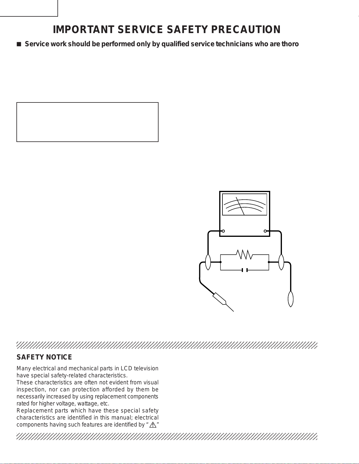
3. To be sure that no shock hazard exists, check for
leakage current in the following manner.
• Plug the AC cord directly into a 110~240 volt AC outlet,
and connect the DC power cable into the receiver's
DC jack. (Do not use an isolation transformer for this
test).
• Using two clip leads, connect a 50k ohm, 10 watt resistor
paralleled by a 0.15µF capacitor in series with all
exposed metal cabinet parts and a known earth ground,
such as electrical conduit or electrical ground connected
to an earth ground.
• Use an AC voltmeter having with 5000 ohm per volt, or
higher, sensitivity or measure the AC voltage drop
across the resistor.
• Connect the resistor connection to all exposed metal
parts having a return to the chassis (antenna, metal
cabinet, screw heads, knobs and control shafts,
escutcheon, etc.) and measure the AC voltage drop
across the resistor.
All checks must be repeated with the AC cord plug
connection reversed. (If necessary, a nonpolarized
adaptor plug must be used only for the purpose of
completing these checks.)
Any reading of 0.75V peak (this corresponds to 0.5
mA. peak AC.) or more is excessive and indicates a
potential shock hazard which must be corrected before
returning the monitor to the owner.
DVM
AC SCALE
50k ohm
10W
0.15 µF
TEST PROBE
TO EXPOSED
METAL PARTS
CONNECT TO
KNOWN EARTH
GROUND
234567890123456789012345678901212345678901234567890123456789012123456789012345678901234567890121
SAFETY NOTICE
Many electrical and mechanical parts in LCD television
have special safety-related characteristics.
These characteristics are often not evident from visual
inspection, nor can protection afforded by them be
necessarily increased by using replacement components
rated for higher voltage, wattage, etc.
Replacement parts which have these special safety
characteristics are identified in this manual; electrical
and shaded areas in the
Schematic Diagrams.
For continued protection, replacement parts must be
identical to those used in the original circuit.
The use of a substitute replacement parts which do not
have the same safety characteristics as the factory
recommended replacement parts shown in this service
manual, may create shock, fire or other hazards.
components having such features are identified by “ å”
234567890123456789012345678901212345678901234567890123456789012123456789012345678901234567890121
2
Replacement Parts Lists and
Page 4

Precautions for using lead-free solder
1 Employing lead-free solder
"All PWBs" of this model employs lead-free solder. The LF symbol indicates lead-free solder, and is attached on
the PWBs and service manuals. The alphabetical character following LF shows the type of lead-free solder.
Example:
L Fa
Indicates lead-free solder of tin, silver and copper.
2 Using lead-free wire solder
When fixing the PWB soldered with the lead-free solder, apply lead-free wire solder. Repairing with conventional
lead wire solder may cause damage or accident due to cracks.
As the melting point of lead-free solder (Sn-Ag-Cu) is higher than the lead wire solder by 40°C, we recommend
you to use a dedicated soldering bit, if you are not familiar with how to obtain lead-free wire solder or soldering
bit, contact our service station or service branch in your area.
3 Soldering
As the melting point of lead-free solder (Sn-Ag-Cu) is about 220°C which is higher than the conventional lead
solder by 40°C, and as it has poor solder wettability , you may be apt to keep the soldering bit in contact with the
PWB for extended period of time. However, Since the land may be peeled off or the maximum heat-resistance
temperature of parts may be exceeded, remove the bit from the PWB as soon as you confirm the steady soldering
condition.
Lead-free solder contains more tin, and the end of the soldering bit may be easily corroded. Make sure to turn on
and off the power of the bit as required.
If a different type of solder stays on the tip of the soldering bit, it is alloyed with lead-free solder. Clean the bit
after every use of it.
When the tip of the soldering bit is blackened during use, file it with steel wool or fine sandpaper.
LC-13B4E
LC-15B4E
Be careful when replacing parts with polarity indication on the PWB silk.
Lead-free wire solder for servicing
Part No, ★ Description Code
ZHNDAi123250E J φ0.3mm 250g(1roll) BL
ZHNDAi126500E J φ0.6mm 500g(1roll) BK
ZHNDAi12801KE J φ1.0mm 1kg(1roll) BM
3
Page 5

BLOCK DIAGRAM
LC-13B4E
LC-15B4E
H
SC3901
ANTENNA
SCART
TUNER
(AV1)
AUDIO IN TV_V
G
F
SC5001
AUDIO OUT
VIDEO OUT
SDA/RXD
SCL/TXD
VIDEO IN
SC_R/G/B
S
2
I
C/UART
SY
V1.SY
TV/AV
SELECTOR
IC806
SC
(AV2) INPUT
J5003
E
J5001
VIDEO
(AV2) INPUT
AUDIO
V1_V
V1.L/R
SIF1
AI_L/R
I2C
SC_L/RO
CHROMA
SELECTOR
IC803
AUDIO AMP
IC1902
AMP
IC808
AMP
IC808
(AV2) INPUT
ANA_IN1+
SC2_IN_L/R
SC1_OUT_L/R
SC1_IN_L/R
CVBS/SY_IN
R/G/B_IN
SC_IN
MSP
IC1901
VPC
IC801
V2VO
SYNC SEP
IC802
2
I
C
UART
E2PROM
IC2010
CSYNC
DACM_L/R
2
I
DACA_L/R
I2C
MICON
IC2001
C
AUDIO AMP
IC304
SC2_OUT_L/R
VPC0~7
SYNC SIGNAL
CONTROL SIGNAL
2
PROM
E
IC2008
RESET
RESET
IC2006
OSD R/G/B
L_ERR
AUDIO ACTIVE FILTER
IC1905
AUDIO AMP
IC3501
~7
YIN0
DPS
IC1201
OFL1
VPC
R/G/B/FB
LEVEL
SHIFT
Q1602,1604,1606
L/R_IN
AO_L/R
MPDA_5
MPCLK_5
DAC1CS
OUTCON
REV
AUDIO
POWER AMP
IC3301
PAVCC(+12V)
GRADATION
POWER
IC1101
FLSP/FRSP
HL/R
R0~7 G0~7 B0~7
V0 V7 V21 V64
V112 V176 V235 V255
VCOM
CSCOM
SPEAKER
HEADPHONE
JACK
AUDIO OUT
LCD
PANEL
P3301
P3302
J5002
J3901
SC1202
SC1203
SC1204
+9V
+8V
+3.3V
+32V
–11V
Q3705
+23V
+17V
VOLTAGE
CONVERTER
IC702
-16V
TEXT R/G/B /FBL
CVBS
R/G/B
TELETEXT
CPU
IC1601
OFL REVERSE
Q3606
2
C
I
SRAM 2M
IC1612
L_ERR
OFL
DC/AC
INVERTER
DRIVE
Q6500
~6505
LAMP ERROR
DETECTOR
Q3601, 3602
DC/AC
TRANS
T6500
~6503
INVVCC(+12V)
HV1/2/3
BACK
LIGHT
LAMP
P3601
P6500
~P6501
REG IC2003
D
J3701
DC12V
REG IC2004
+5V
INPUT
REG IC707
PAVCC
REG IC705
C
+3.3V
+3.4V
+34V
Q3707
IC3702
Q3708
DC/DC
CONVERTER
SIGVCC
T3701
Q3709
FLASH 4M
B
REG IC706
PWM IC3701
A
INVVCC
B12V1A
Q3703
REG IC805
REG IC704
REG IC1602
+5V
+1.8V
+3.3V
+3.3V
REG IC703
REG IC1607
REG IC1605
-8V
+5V
+3.3V
+2.5V
IC1611
P4001
KEY
P4004
REMOTE
CONTROL
RECEIVER
24
121110987654321
25
Page 6

LC-13B4E
LC-15B4E
ADJUSTING PROCEDURE OF EACH SECTION
The best adjustment is made before shipping. If any position deviation is found or after part replace is performed,
adjust as follows.
Preparation for adjustments
Use the dedicated AC adaptor or stable DC power supply.
AC adaptor: UADP-A034WJPZ
DC power supply: 12V 4.5A
1.Adjusting procedure
• Checker adjustment
Power ON (Adjustment processing mode) → +B adjustment → Counter bias adjustment → TAMP (Contrast)
adjustment → White balance adjustment
2.Entering the adjustment processing mode
There are the following two methods.
• Setting the pin (81)(KEY4) or pin (82)(KEY5) of IC2001 (microprocessor) to GND, turn on the power .
• A “POWER” key is made on with pushing an “TV/VIDEO” and “MENU” keys at the same time.(K of the inspection
process mode is displayed by the upper left of the image plane.) → Next, “CH (Ù)” and “VOL (–)” keys are pushed
at the same time.(It becomes the image plane of the adjustment process mode.).....When it is canceled, it is made
to turn it off.(Even off in the “MAIN POWER” key, off with R/C are good.)
3.Key operation in the adjustment process mode
• The receiving channel UP/DOWN is performed with the “CH (ù)/(Ù)” keys.
One push ... The UP/DOWN tuning is performed per channel.
Continuous push ... The UP/DOWN search is performed until a next receivable station is found.
• Various adjustments
The adjustment is performed for each item by the “MENU”, “Menu cursor”, “CH (ù)/(Ù)” or “VOL (+)/(–)” keys
(LCD TV set and remote control).
• Adjustment item is chosen with the Menu cursor upward/downward keys.
• The adjustment item makes a toggle operation with the “MENU” key input. (Next item)
If the “MENU” key is input while the bottom item is selected, it moves to the top item on the next page.
• Press the auto preset button on the remote controller in the adjustment process mode, and the top item of the
next page will show up regardless of which item appears now.
Page 1 → Page 2 → ... → Page 57 → Page 1
• Press the manual memory button on the remote controller in the adjustment process mode, and the top item of
the same page will show up.
• UP/DOWN of each adjustment vale selected is performed with the VOL (+)/(–) keys input.
13
Page 7

LC-13B4E
LC-15B4E
4.Initialization
When the microprocessor (IC2001) or the EEPROM (IC2008, IC2010) has been replaced or when the EEPROM
has been initialized, readjust the each adjustments.
4-1. Connect the pins (81) and (82) of IC2001 (microprocessor) to GND, and turn on the power.
4-2. Select the model name to (A522).
4-3. Select the inch size (13)~1 or (15)~2.
4-4. LED changes green from red after setting finish and about 15 seconds, initialization is completed, and it
becomes adjustment mode.
4-5. Writing the model-by-model data
For the Ver.1.10A microprocessor, get it initialized first and then make the settings, listed below, on it. (The
microprocessor version is indicated at the bottom of Adjustment Process Page 1.)
ËLC-13B4E
Ver.1.10A data reprogramming (INCH SIZE [13])
Adjustment process page
2
2
4
4
4
4
4
4
4
4
4
4
13
13
13
13
13
R GAIN
B GAIN
TV GEQ BAND1
TV GEQ BAND2
TV GEQ BAND3
TV GEQ BAND4
TV GEQ BAND5
EXT GEQ BAND1
EXT GEQ BAND2
EXT GEQ BAND3
EXT GEQ BAND4
EXT GEQ BAND5
SECAM TV COLOR
SECAM A V COLOR
SECAM BRIGHTNESS
SECAM TV CONTRAST
SECAM A V CONTRAST
Item
OSD settings
0 → -26
0 → -6
+1.0 → +1.5
0.0 → -0.5
0.0 → +0.5
-1.5 → +0.5
-2.0 → +1.0
+1.0 → +1.5
0.0 → -0.5
0.0 → +0.5
-1.5 → +0.5
-2.0 → +1.0
37 → 41
37 → 41
-13 → -18
54 → 58
54 → 58
ËLC-15B4E
Ver.1.10A data reprogramming (INCH SIZE [15])
Adjustment process page
2
4
4
4
4
13
13
13
13
13
4-6. Precautions in replacing the EEPROMs (IC2008 and IC2010)
When the EEPROMs (IC2008 and IC2010) have been replaced, be sure to replace also the microprocessor
(IC2001) with the one "Part No. RH-iXA522WJN1Q".
The version of the RH-iXA522WJN1Q microprocessor is 1.20A.
Note:
~1:LC-13B4E
~2:LC-15B4E
B GAIN
TV GEQ BAND4
TV GEQ BAND5
EXT GEQ BAND4
EXT GEQ BAND5
SECAM TV COLOR
SECAM A V COLOR
SECAM BRIGHTNESS
SECAM TV CONTRAST
SECAM A V CONTRAST
Item
OSD settings
0 → +14
+0.5 → 0.0
+1.5 → +1.0
+0.5 → 0.0
+1.5 → +1.0
37 → 41
37 → 41
-13 → -18
54 → 58
54 → 58
14
Page 8

5.Adjustment
5-1. +B adjustment...Page 1 +B-ADJ
Adjust the voltage of the pin (4) of P1902 to 5.00 ±0.02V with R3714.
Note: Since 5.0V is a reference voltage of all power voltage, adjust it precisely.
5-2. Counter-bias adjustment
Vary the "COM BIAS" setting on Page 2 of the adjustment process mode so that the contrast be sharpest
(black looks most sinking).
5-3. TAMP adjustment
1) Receive the upper left of 75% white half colour bar signal.
2) See if the “Y” reading on page 2 of the adjustment process mode is somewhere following. If not, make the
“PAL TAMP” adjustment to get the “Y” reading in the range of AE thru BD.
3) If the adjustment of “PAL TAMP” is executed, write its adjustment value to the “SECAM TAMP” manually.
(Screen of the page 2 of the adjustment processing menu OSD)
0 1 2 3 4 5 6 7 8 9 10 11 12 13 14 15 16 17 18 19 20 21 22 23 24 25 26
0
1
2
3
4
5
6
7
8
9
10
11
12
13
2
COM B I AS 9 0
PAL TAMP 21
SECAM TAMP 21
RCU TOF F
GCUT OF F
BCU TOF F
RGA I
GG
BGA I
TAMP
TAMP
AI
Y
N 0
N
N
H
L
B
B
A
LC-13B4E
LC-15B4E
0
0
0
0
0
6
D
E
Y Data
(White 75%)
5-4. White balance adjustment
Adjust “RCUTOFF” and “BCUTOFF” on the page 2 of the adjustment processing so as to obtain the colour
of the same level as the standard set.
15
Page 9

LC-13B4E
LC-15B4E
6. Factory Setting
6-1. Perform a factory setting after completing all adjustments.
6-2. A “POWER” keys is made on with pushing an “TV/VIDEO” and “MENU” keys at the same time.
6-3. “K” of the inspection process mode is displayed on the screen upper left.
6-4. CH (ù) and VOL (+) keys are pushed about 2 seconds at the same time.
6-5. Release keys, if “E” is displayed on the screen upper left and “COMPLETE” is displayed on the bottom of it.
6-6. After a while, a power will be in a standby mode and a setup will be finished.
Note: “First installation” serves on “Deutsch”.
7. Lamp error detection
7-1. Functional description
This LCD colour television has a function (lamp error detection) to be turned OFF automatically for safety
when the lamp or lamp circuit is abnormal.
If the lamp or lamp circuit is abnormal, or some other errors happen, and the lamp error detection is executed,
the followings occur.
1 The main unit of television is turned OFF 5 seconds after it is turned ON. (The power LED on the front side
of TV turns from green to red.)
2 If the situation 1 happens 5 times sequentially , television can not be turned ON. (The power LED remains
red.)
7-2. Countermeasures
7-2-1.Check when turning OFF the lamp error detection
When television is turned OFF by the lamp error detection mentioned above, it enters the adjustment
process with the power LED red. Entering the adjustment process turns OFF the error detection and turns
ON TV .
This enables the operation check to detect errors in the lamp or lamp circuit.
Check whether "ERROR NO RESET" on line 3, page 1 of the adjustment process is 1 or more. If it is 1 or
more, it indicates the lamp error detection was executed.
7-2-2.Resetting of the lamp error count
After confirming that the lamp or lamp circuit is normal, reset the lamp error count. Select "ERROR NO
RESET" on line 3, page 1 of the adjustment process and set the number to 0 using the volume button.
Page 1 of the adjustment process
1
M O D E L A522
INCH SIZE ~3
ERROR NO RESET 5
PUBLIC MODE OFF
EXT CONTROL OFF
EXT MODE UART
UPDATE MODE NORMAL
TEXT RESET OFF
Reset 0
V E R R O M 1 . 1 0 A
Afterwards, perform the operation check to confirm that the lamp error detection does not function.
Note:~3 LC-13B4E=13, LC-15B4E=15
16
Page 10

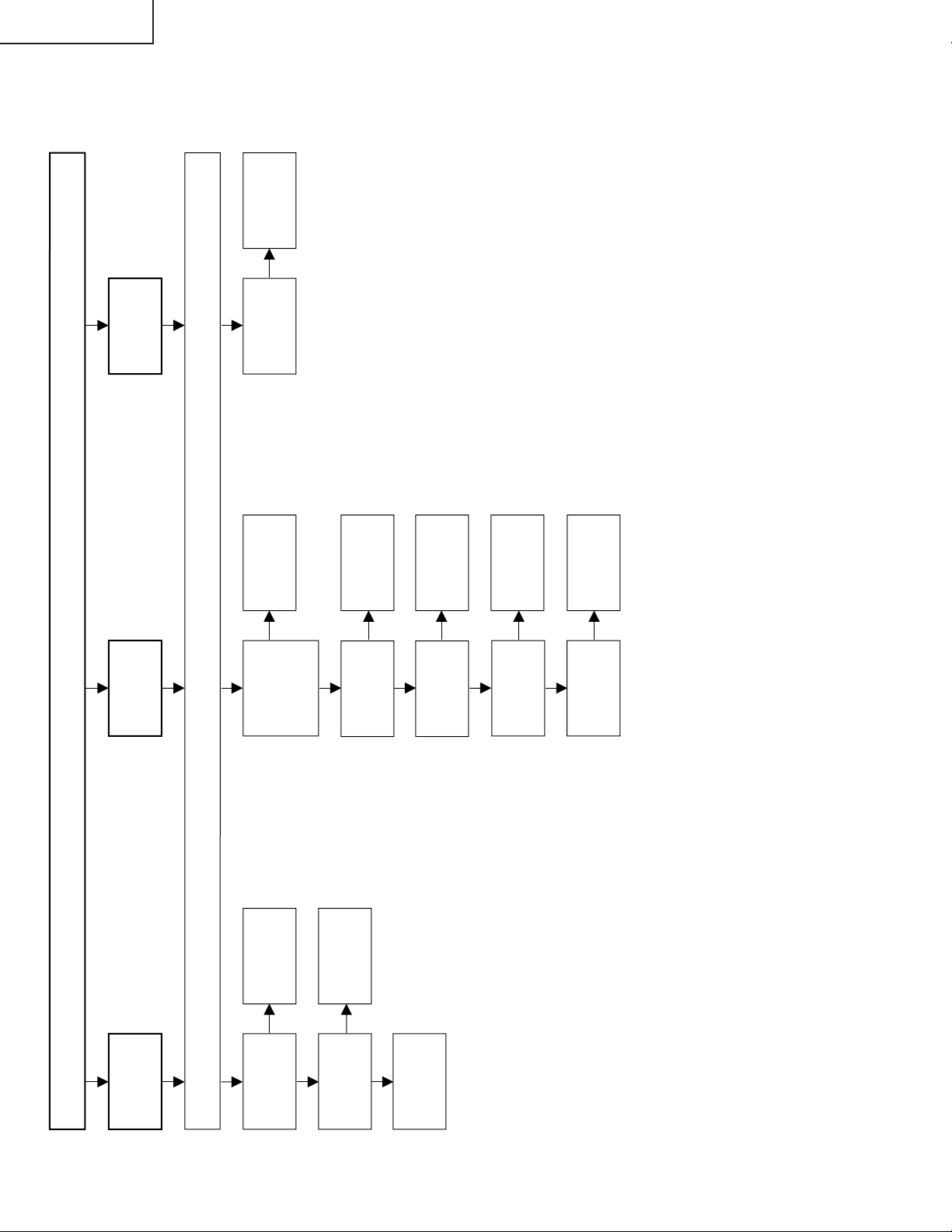
TROUBLE SHOOTING TABLE
No picture and No sound
Check all the settings microprocessor's adjust process menu.
Do F3301 and F3302
function?
Are T3701's secondary
outputs, +34V, +9V, +5V
and -11V normal?
Remove F3301 and F3302
and check the load side.
Is there short-circuiting?
Is there short-circuiting of
T3701 primary side periphery,
Q3703, Q3704 and S4701.
Replace F3301 and F3302.
Check S4701 and
connection cable.
Is T3701's primary oscillator
waveform normal?
Check T3701's secondary
load.
Yes Yes
No
No
No No
No
Yes
Check J3701 periphery and
connection cable.
Replace F6500~F6501.
Is the pin (120) of IC1201 in
the "H" state?
Is the output of Q3606 in the
"
L
"
state?
Yes
Yes
No
No
No
Yes
Yes
Check the OFL1 line, IC1201
and their peripheral parts.
Check the OFL line, Q3606
and their peripheral parts.
Check T6500~T6503,
Q6500~Q6505 and
connection cable.
Back light lamp failure to light up
Is the primary side of
T6500 ~T6503 periphery
short-circuiting?
Replace the back light lamp
with new one and check
again.
LC-13B4E
LC-15B4E
17
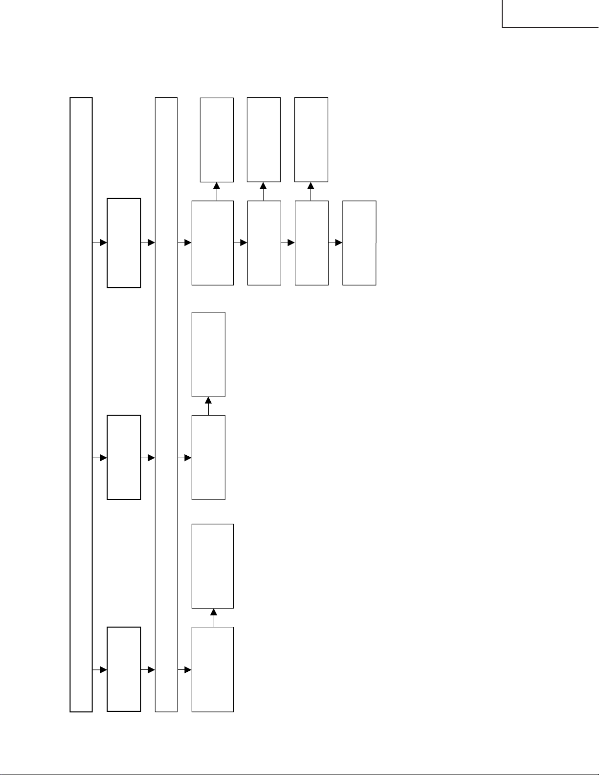
Page 11
LC-13B4E
No picture (1/3)
Check all the settings microprocessor's adjust process menu.
Is in/output of
IC801 normal?
Is in/output of
IC1201 normal?
Check IC801
and its
peripheral parts.
Check IC1201
and its
peripheral parts.
Check LCD
panel voltages
and waveform.
Yes
Yes
No
No
No picture
at all
Is voltages at
pins (6), (7) and
(18) tuner
normal?
Is output at pin
(13) of tuner
normal?
Check the
power line.
Check tuner
and its
peripheral parts.
Is input at pin
(16) of IC806
normal?
Is the pin (3) of
IC806 at "H"
state?
Yes
Yes
No
No
No
No
No
Yes
No TV output
Is the pin (48)
of IC2001 at "H"
state?
Yes
Check the its
line.
Check the its
line.
Check IC806
and its
peripheral parts.
Is input at pin
(14) of IC806
normal?
Check V1_V
line and its
peripheral parts.
No
No VIDEO 2
output
LC-15B4E
TROUBLE SHOOTING TABLE (Continued)
18
Page 12
TROUBLE SHOOTING TABLE (Continued)
No picture (2/3)
Check all the settings microprocessor's adjust process menu.
Is input at pin
(14) of IC806
normal?
Check the V2_V
line and its
peripheral parts.
No
No VIDEO 1
output
Check the SY-line,
SC-line and their
peripheral parts.
Is input at pin (9)
of IC806 and pin
(1) of IC803
normal?
No
No S-VIDEO
output
Check IC1201
and its
peripheral parts.
No
Yes
Yes
No TELETEXT
output
Is input at pins
(136), (137), (138),
and (142) of
IC1201 normal?
No
Check the R, G
and B line.
Is output at pins
(57)~(59) of IC1601
normal?
No
Yes
Check V2VO line
and its peripheral
parts.
Is input at pin (21) of
IC1601 normal?
Check IC1601 and its
peripheral parts.
LC-13B4E
LC-15B4E
19
Page 13

LC-13B4E
No picture (3/3)
Check all the settings microprocessor's adjust process menu.
Is output of
R0~R7
normal?
Is output of
G0~G7
normal?
Is output of
B0~B7
normal?
Yes
Yes
No
No
No
Colour is
unusual
Is in/output of
SPIO and
SPOI normal?
No
No picture
image
inversion
No
Gradation
defect
Is output of U/D
normal?
Yes
No
Check R1227 and
its peripheral parts.
Check R1235 and
its peripheral parts.
Check IC1202,
Q1204 and their
peripheral parts.
Check R1228 and
its peripheral parts.
Check R1232 and
its peripheral parts.
Is output V0, V7, V21,
V64, V112, V176,
V235 and V255
normal?
Check IC1101 and its
peripheral parts.
LC-15B4E
TROUBLE SHOOTING TABLE (Continued)
20
Page 14

TROUBLE SHOOTING TABLE (Continued)
No sound (1/2)
Check all the settings microprocessor's adjust process menu.
Is the pin (53) of
IC2001 in the
"L" state?
Is output at pins
(27) and (28) of
IC1901 normal?
Is output at pins
(1) and (7) of
IC1905 normal?
Yes
Yes
No
No
No
No sound
from front
speakers
Yes
Muting effect is
on. Check the
FSMUTE line.
Check IC1901
and its
peripheral parts.
Check IC1905
and its
peripheral parts.
Is the pin (52) of
IC2001 in the
"L" state?
Is output at pins
(24) and (25) of
IC1901 normal?
Is output at pins
(1) and (7) of
IC304 normal?
Yes
Yes
No
No
No
Yes
Muting effect is
on. Check the
HP_MUTE line.
Check IC1901
and its
peripheral parts.
Check IC304
and its
peripheral parts.
No sound
from
headphone
TV sound
failure
Is output at pins
(33) and (34) of
IC1901 normal?
Is output at pins
(1) and (7) of
IC3501 normal?
Check IC1901
and its
peripheral parts.
Check IC3501
and its
peripheral parts.
Yes
No
No
No
No sound
from output
line
Check the tuner
and its
peripheral parts.
Yes
No
Is output at pin
(11) of Tuner
normal?
Is input at pin
(67) of IC1901.
Check IC1901
and its
peripheral
parts.
Check
Headphone Jack
and connection
cable.
No
Is output at pins
(8) and (12) of
IC3301 normal?
Check IC3301
and its
peripheral parts.
Check front
speaker and
connection
cable.
Yes
LC-13B4E
LC-15B4E
21
Page 15

LC-13B4E
No sound (2/2)
Check all the settings microprocessor's adjust process menu.
Yes
No
No
No sound from SCART
No
SCART sound failure
Yes
No
Check IC1901 and its
peripheral parts.
Is output at pins (36) and (37) of
IC1901 normal?
Check IC1902 and its
peripheral parts.
Is output at pins (1) and (7) of
IC1902 normal?
Check their lines and their
peripheral parts.
Is input at pins (53) and (54) of
IC1901 normal?
Check IC1901 and its
peripheral parts.
Is output at pins (27) and (28) of
IC1901 normal?
LC-15B4E
22
Page 16

OVERALL WIRING DIAGRAM
H
G
F
LC-13B4E
LC-15B4E
E
D
C
B
A
121110987654321
26
27
Page 17

SCHEMATIC DIAGRAM
Ë
R/C, LED and OPERATION Unit
H
G
F
LC-13B4E
LC-15B4E
E
D
C
B
A
654321
29
Page 18

LC-13B4E
LC-15B4E
Ë
MAIN Unit-1/7
H
G
F
E
D
C
B
A
121110987654321
30
31
Page 19

LC-13B4E
LC-15B4E
Ë
MAIN Unit-2/7
H
G
F
E
D
C
B
A
121110987654321
32
33
Page 20

LC-13B4E
LC-15B4E
Ë
MAIN Unit-3/7
H
G
F
E
D
C
B
A
121110987654321
34
35
Page 21

LC-13B4E
LC-15B4E
Ë
MAIN Unit-4/7
H
G
F
E
D
C
B
A
121110987654321
36
37
Page 22

LC-13B4E
LC-15B4E
Ë
MAIN Unit-5/7
H
G
F
E
D
C
B
A
121110987654321
38
39
Page 23

LC-13B4E
LC-15B4E
Ë
MAIN Unit-6/7
H
G
F
E
D
C
B
A
121110987654321
40
41
Page 24

LC-13B4E
LC-15B4E
Ë
MAIN Unit-7/7
H
G
F
E
D
C
B
A
121110987654321
42
43
Page 25

LC-13B4E
LC-15B4E
Ë
TUNER Unit-1/4
H
G
F
E
D
C
B
A
121110987654321
44
45
Page 26

LC-13B4E
LC-15B4E
Ë
TUNER Unit-2/4
H
G
F
E
D
C
B
A
121110987654321
46
47
Page 27

LC-13B4E
LC-15B4E
Ë
TUNER Unit-3/4 (LC-13B4E)
H
G
F
E
D
C
B
A
121110987654321
48
49
Page 28

LC-13B4E
LC-15B4E
Ë
TUNER Unit-3/4 (LC-15B4E)
H
G
F
E
D
C
B
A
121110987654321
50
51
Page 29

LC-13B4E
LC-15B4E
Ë
TUNER Unit-4/4
H
G
F
E
D
C
B
A
121110987654321
52
53
Page 30

LC-13B4E
LC-15B4E
Ë
H
G
F
INVERTER Unit
E
D
C
B
A
654321
54
Page 31

CHASSIS LAYOUT
LC-13B4E
LC-15B4E
H
MAIN Unit
G
F
E
OPERATION Unit
INVERTER Unit
TUNER Unit
D
C
B
R/C, LED Unit
A
654321
23
Page 32

LC-13B4E
LC-15B4E
Ref. No. Part No. ★ Description Code Ref. No. Part No. ★ Description Code
PARTS LIST
P ARTS REPLACEMENT
Replacement parts which have these special safety characteristics
identified in this manual; electrical components having such features
are identified by
and Schematic Diagrams. The use of a substitute replacement part
which does no have the same safety characteristic as the factory
recommended replacement parts shown in this service manual may
create shock, fire or other hazards.
"HOW TO ORDER REPLACEMENT P ARTS"
To have your order filled promptly and correctly, please furnish the
following informations.
1. MODEL NUMBER 2. REF. NO.
3. P AR T NO . 4. DESCRIPTION
Ref. No. Part No. ★ Description Code
PRINTED WIRING BOARD ASSEMBLIES
å and shaded areas in the Replacement Parts Lists
★ MARK: SPARE PARTS-DELIVERY SECTION
(NOT REPLACEMENT ITEM)
LC-13B4E
DUNTKB750FE01 – MAIN Unit —
DUNTKB751DE01 – TUNER Unit —
DUNTKB752DE01 – R/C,LED Unit —
DUNTKB753DE01 – OPERATION Unit —
DUNTKB754DE01 – INVERTER Unit —
LC-15B4E
DUNTKB750FE02 – MAIN Unit —
DUNTKB751DE02 – TUNER Unit —
DUNTKB752DE02 – R/C,LED Unit —
DUNTKB753DE02 – OPERATION Unit —
DUNTKB754DE02 – INVERTER Unit —
DUNTKB750FE01:LC-13B4E
DUNTKB750FE02:LC-15B4E
MAIN UNIT
INTEGRATED CIRCUITS
IC701 VSUMX2N++++-1Y J UMX2N AB
IC702 VHiNJU7662M-1Y J NJU7662M(TE2) AL
IC703 VHiNJ79M08D-1Y J NJM79M08DL1A AF
IC704 VHiPQ1R33//-1Y J PQ1R33 AE
IC705 VHiPQ1R34++-1Y J PQ1R34 AE
IC706 VHiLM1117MJ-1Y J LM1117MPX-ADJ AF
IC707 VHiMM1573DN-1Y J MM1573DNRE AD
IC801 VHiVPC3230D1EQ J VPC3230D-QA-B3 BD
IC802 VHiBA7046F/-1Y J BA7046F AF
IC803 VHiNJM2233V-1Y J NJM2233V AE
IC805 VHiMM1563DF-1Y J MM1563DFBE AE
IC806 VHiNJM2293M-1Y J NJM2293M(TE1) AG
IC808 VHiNJM2268M-1Y J NJM2268M-TE1 AF
IC1101 VHiBD8120FP-1Y J BD8120FP AX
IC1201 VHiDPS9450+-1Q J DPS9450A-XZ-A1 BD
IC1202 VHiTC4W66U/-1Y J TC4W66FU AE
IC1601 VHiSDA5550M-1Q J SDA5550M AZ
IC1602 VHiBA05FP++-1Y J BA05FP-E2 AF
IC1603 VHiPST3228N1EY J PST3228NR AB
IC1604 VHiMM1501XN-1Y J MM1501XNRE AE
IC1605 VHiMM1562FF-1Y J MM1562FFBE AE
IC1606 VHiPST3221N1EY J PST3221NR AB
IC1607 VHiMM1563DF-1Y J MM1563DFBE AE
IC1608 VHiNC7SZ58P-1Y J NC7SZ58P6X AE
IC1609 VHiTC7SZ08U-1Y J TC7SZ08FU AE
IC1610 VHiLCX157MT-1Y J 74LCX157MTCX AE
IC1611 RH-iXA388WJZZQ J MBM29DL400TC90 AY
IC1612 VHi62S8308X-1Q J A62S8308X-70SI AY
IC1614 VHiVHC08MTC1EY J 74VHC08MTCX AD
IC1615 VHi74LVX86M-1Y J 74LVX86MTCX AD
IC2001 RH-iXA522WJZZQ J M306V3MG-102FP BB
IC2003 VHiMM1573DN-1Y J MM1573DNRE AD
IC2004 VHiPQ1L503M-1Y J PQ1L503M2SP AD
IC2005 VHiBU4052FV-1Y J BU4052BCFV-E2 AE
IC2006 VHiBD4729G+-1Y J BD4729G-TR AD
IC2007 VHiNC7S02M5-1Y J NC7S02M5 AD
IC2008 VHiBR24C32F-1Y J BR24C32F-E2 AH
IC2009 VHiTC4W66U/-1Y J TC4W66FU AE
IC2010 VHiBR2416E2-1Y J BR24C16F AK
IC2011 VHiTC4W66U/-1Y J TC4W66FU AE
LCD PANEL
NOTE: THE PARTS HERE SHOWN ARE SUPPLIED AS AN
ASSEMBLY BUT NOT INDEPENDENTLY.
RLCDTA012WJN1 J 13" LCD Panel Unit CT
(LC-13B4E)
RLCDTA013WJN1 J 15" LCD Panel Unit CZ
(LC-15B4E)
Q701 VS2SA1037KQ-1Y J 2SA1037KQ AA
TRANSISTORS
Q702 VSFMMT718//-1Y J FMMT718 AE
Q703 VSDTC144EE/-1Y J DTC144EE AA
Q803 VS2SA1530AR-1Y J 2SA1530AR AB
Q804 VS2SA1530AR-1Y J 2SA1530AR AB
Q806 VS2SA1530AR-1Y J 2SA1530AR AB
Q1101 VSFMMT718//-1Y J FMMT718 AE
Q1102 VS2SC4520//-1Y J 2SC4520 AE
Q1103 VS2SA1729//-1Y J 2SA1729 AF
Q1104 VSDTC144EE/-1Y J DTC144EE AA
Q1105 VS2SC4520//-1Y J 2SC4520 AE
Q1106 VS2SA1729//-1Y J 2SA1729 AF
Q1204 VSDTC144EE/-1Y J DTC144EE AA
Q1601 VS2SA1530AR-1Y J 2SA1530AR AB
Q1602 VS2SA1530AR-1Y J 2SA1530AR AB
Q1603 VSDTC144TE/-1Y J DTC144TE AB
Q1604 VS2SA1530AR-1Y J 2SA1530AR AB
Q1605 VS2SC3928AR-1Y J 2SC3928AR AB
Q1606 VS2SA1530AR-1Y J 2SA1530AR AB
Q1607 VS2SA1530AR-1Y J 2SA1530AR AB
Q2001 VSUM5K1NTR+-1Y J UM5K1NTR AC
Q2002 VSDTC114EE/-1Y J DTC114EE AB
Q2003 VSUPA606T//-1Y J UPA606T AD
Q2005 VSUPA606T//-1Y J UPA606T AD
Q2006 VSDTC114EE/-1Y J DTC114EE AB
Q2007 VSUPA606T//-1Y J UPA606T AD
65
Page 33

LC-13B4E
LC-15B4E
Ref. No. Part No. ★ Description Code Ref. No. Part No. ★ Description Code
DUNTKB750FE01:LC-13B4E
DUNTKB750FE02:LC-15B4E
MAIN UNIT (Continued)
DIODES
D701 RH-EX1247CEZZY J Zener Diode, 5.6V AB
D702 VHDDAN222//-1Y J Diode AA
D703 RH-EX1245CEZZY J Zener Diode, 5.1V AB
D704 VHDDAN222//-1Y J Diode AA
D706 VHDDAN222//-1Y J Diode AA
D707 VHDDAN222//-1Y J Diode AA
D708 RH-EX1245CEZZY J Zener Diode, 5.1V AB
D709 VHDDAN222//-1Y J Diode AA
D710 VHD1SS250//1EY J Diode AB
D711 VHDDAN202K/-1Y J Diode AB
D712 VHDDAN222//-1Y J Diode AA
D713 VHDRB481K++-1Y J Diode AD
D714 VHDRB491D++-1Y J Diode AD
D1101 VHD1SS250//1EY J Diode AB
D1102 VHDDAN222//-1Y J Diode AA
D1103 VHD1SS250//1EY J Diode AB
D1104 VHD1SS250//1EY J Diode AB
D2001 RH-EX1232CEZZY J Zener Diode AB
D2002 VHDDAN202K/-1Y J Diode AB
D2003 VHDDAN202K/-1Y J Diode AB
P ACKAGED CIRCUITS
X801 RCRSC0012CEZZY J Crystal AH
X1201 RCRSC0012CEZZY J Crystal AH
X1601 RCRSCA002WJZZY J Crystal AG
FIL TER AND COILS
X2001 RFiLZ0169TAZZY J Filter AD
FL801 RCiLFA033WJZZY J Coil AG
FL802 RCiLFA033WJZZY J Coil AG
L701 RCiLPA143WJZZY J Coil AD
L702 VP-1M470J5R4NY J Peaking 47µH AC
L804 RCiLPA143WJZZY J Coil AD
L805 RCiLPA143WJZZY J Coil AD
L806 VP-9N3R3KR46NY J Peaking 3.3µH AC
L807 VP-9N3R3KR46NY J Peaking 3.3µH AC
L808 VP-9N3R3KR46NY J Peaking 3.3µH AC
L1204 VPCGM220M0R5NY J Peaking 22µH AB
L1205 VPCGM220M0R5NY J Peaking 22µH AB
L1206 VPCGM220M0R5NY J Peaking 22µH AB
L1207 VPCGM220M0R5NY J Peaking 22µH AB
L1601 VP-1M270J3R8NY J Peaking 27µH AC
CAPACITORS
C701 VCKYCY1EF104ZY J 0.1 25V Ceramic AA
C702 VCEASK1CN227MY J 220 16V Electrolytic AC
C703 RC-EZA123WJZZY J 100 6.3V Electrolytic AC
C704 VCKYTV1CB105KY J 1 16V Ceramic AC
C705 VCKYTV1CB105KY J 1 16V Ceramic AC
C706 RC-KZ0075TAZZY J 2.2 16V Ceramic AC
C707 RC-KZA041WJZZY J 10 10V Ceramic AC
C708 RC-EZA129WJZZY J 2.2 50V Electrolytic AB
C709 VCKYTV1CB105KY J 1 16V Ceramic AC
C710 VCKYTV1CB105KY J 1 16V Ceramic AC
C711 RC-EZA132WJZZY J 10 50V Electrolytic AC
C712 RC-KZA041WJZZY J 10 10V Ceramic AC
C713 RC-KZA041WJZZY J 10 10V Ceramic AC
C714 RC-KZA041WJZZY J 10 10V Ceramic AC
C715 RC-EZA132WJZZY J 10 50V Electrolytic AC
C716 RC-KZA041WJZZY J 10 10V Ceramic AC
C717 VCKYTV1CB105KY J 1 16V Ceramic AC
C718 RC-KZA041WJZZY J 10 10V Ceramic AC
C719 RC-EZA123WJZZY J 100 6.3V Electrolytic AC
C720 VCEASH0JN227MY J 220 6.3V Electrolytic AC
C721 VCKYCY1EF104ZY J 0.1 25V Ceramic AA
C722 RC-EZA131WJZZY J 4.7 50V Electrolytic AC
C723 VCKYCY1EF104ZY J 0.1 25V Ceramic AA
C724 RC-EZA132WJZZY J 10 50V Electrolytic AC
C725 VCKYCY1EF104ZY J 0.1 25V Ceramic AA
C726 RC-EZA132WJZZY J 10 50V Electrolytic AC
C727 VCKYTV1CB105KY J 1 16V Ceramic AC
C728 VCKYCY1HF103ZY J 0.01 50V Ceramic AA
C801 RC-KZA041WJZZY J 10 10V Ceramic AC
C802 RC-KZA041WJZZY J 10 10V Ceramic AC
C803 VCKYCY1EF104ZY J 0.1 25V Ceramic AA
C804 RC-KZA041WJZZY J 10 10V Ceramic AC
C805 RC-KZA041WJZZY J 10 10V Ceramic AC
C806 VCKYCY1AB105KY J 1 10V Ceramic AB
C807 VCKYCY1HB222KY J 2200p 50V Ceramic AA
C808 VCCCCY1HH101JY J 100p 50V Ceramic AA
C809 RC-KZA041WJZZY J 10 10V Ceramic AC
C810 VCKYCY1EF104ZY J 0.1 25V Ceramic AA
C812 RC-KZA041WJZZY J 10 10V Ceramic AC
C813 VCKYCY1EF104ZY J 0.1 25V Ceramic AA
C814 VCKYCY1AB105KY J 1 10V Ceramic AB
C815 VCKYCY1HB102KY J 1000p 50V Ceramic AA
C818 RC-EZA135WJZZY J 47 6.3V Electrolytic AC
C819 VCKYCY1EF104ZY J 0.1 25V Ceramic AA
C820 RC-EZA122WJZZY J 22 6.3V Electrolytic AB
C821 VCKYTV1CF684ZY J 0.68 16V Ceramic AB
C822 RC-KZA030WJZZY J 2.2 10V Ceramic AB
C823 VCKYTV1CF684ZY J 0.68 16V Ceramic AB
C824 VCKYCY1EF104ZY J 0.1 25V Ceramic AA
C826 RC-EZA123WJZZY J 100 6.3V Electrolytic AC
C828 RC-KZ1025CEZZY J 1 10V Ceramic AB
C829 RC-EZA123WJZZY J 100 6.3V Electrolytic AC
C830 VCKYCY1EF104ZY J 0.1 25V Ceramic AA
C831 RC-KZ1025CEZZY J 1 10V Ceramic AB
C832 VCKYCY1EF104ZY J 0.1 25V Ceramic AA
C833 RC-EZA123WJZZY J 100 6.3V Electrolytic AC
C835 VCKYCY1HB331KY J 330p 50V Ceramic AA
C836 VCKYCY1HB331KY J 330p 50V Ceramic AA
C837 RC-EZA124WJZZY J 10 16V Electrolytic AB
C838 VCKYCY1HB331KY J 330p 50V Ceramic AA
C840 VCKYCY1EF104ZY J 0.1 25V Ceramic AA
C843 VCCCCY1HH7R0DY J 7p 50V Ceramic AA
C844 VCKYCY1EF104ZY J 0.1 25V Ceramic AA
C845 VCCCCY1HH7R0DY J 7p 50V Ceramic AA
C846 RC-EZA134WJZZY J 220 6.3V Electrolytic AC
C847 VCKYCY1CF224ZY J 0.22 16V Ceramic AB
C848 VCKYCY1CF224ZY J 0.22 16V Ceramic AB
C849 VCKYCY1CF224ZY J 0.22 16V Ceramic AB
C850 RC-KZ0117TAZZY J 4.7 6.3V Ceramic AD
C851 RC-KZ1025CEZZY J 1 10V Ceramic AB
C852 RC-KZ1025CEZZY J 1 10V Ceramic AB
C853 VCKYCY1EF104ZY J 0.1 25V Ceramic AA
C854 VCKYCY1EF104ZY J 0.1 25V Ceramic AA
C855 RC-KZ1025CEZZY J 1 10V Ceramic AB
C856 RC-KZ1025CEZZY J 1 10V Ceramic AB
C857 VCKYCY1EF104ZY J 0.1 25V Ceramic AA
C863 VCKYCY1EF104ZY J 0.1 25V Ceramic AA
C867 VCKYCY1EB473KY J 0.047 25V Ceramic AA
C868 VCKYCY1EB473KY J 0.047 25V Ceramic AA
C869 VCKYCY1EB473KY J 0.047 25V Ceramic AA
C870 RC-KZA030WJZZY J 2.2 10V Ceramic AB
C871 RC-KZA030WJZZY J 2.2 10V Ceramic AB
C872 VCCCCY1HH471JY J 470p 50V Ceramic AA
C873 VCKYCY1AB224KY J 0.22 10V Ceramic AB
C874 VCKYCY1AB224KY J 0.22 10V Ceramic AB
C875 VCKYCY1AB224KY J 0.22 10V Ceramic AB
C1101 VCKYCY1EF104ZY J 0.1 25V Ceramic AA
C1102 RC-EZ1339CEZZY J 220 16V Electrolytic AD
C1104 VCKYCY1EF104ZY J 0.1 25V Ceramic AA
C1105 VCCCCY1HH181JY J 180p 50V Ceramic AA
C1106 VCKYCY1EF104ZY J 0.1 25V Ceramic AA
C1107 RC-KZA041WJZZY J 10 10V Ceramic AC
C1108 VCCCCY1HH560JY J 56p 50V Ceramic AB
C1109 RC-KZA041WJZZY J 10 10V Ceramic AC
C1110 VCKYCY1EF104ZY J 0.1 25V Ceramic AA
C1111 VCKYCY1EF104ZY J 0.1 25V Ceramic AA
C1112 VCKYCY1HB103KY J 0.01 50V Ceramic AA
C1113 VCKYCY1HB103KY J 0.01 50V Ceramic AA
C1114 VCCCCY1HH560JY J 56p 50V Ceramic AB
C1115 VCKYTV1CB334KY J 0.33 16V Ceramic AC
C1116 VCKYTV1CB105KY J 1 16V Ceramic AC
66
Page 34

LC-13B4E
LC-15B4E
Ref. No. Part No. ★ Description Code Ref. No. Part No. ★ Description Code
DUNTKB750FE01:LC-13B4E
DUNTKB750FE02:LC-15B4E
MAIN UNIT (Continued)
C1117 VCKYTV1CB105KY J 1 16V Ceramic AC
C1118 VCKYCY1EB104KY J 0.1 25V Ceramic AB
C1119 RC-KZA041WJZZY J 10 10V Ceramic AC
C1122 RC-EZ1339CEZZY J 220 16V Electrolytic AD
C1204 VCKYCY1EF104ZY J 0.1 25V Ceramic AA
C1205 VCKYCY1EF104ZY J 0.1 25V Ceramic AA
C1206 VCKYCY1EF104ZY J 0.1 25V Ceramic AA
C1207 VCKYCY1EF104ZY J 0.1 25V Ceramic AA
C1208 VCKYCY1EF104ZY J 0.1 25V Ceramic AA
C1209 VCCCCY1HH7R0DY J 7p 50V Ceramic AA
C1210 VCCCCY1HH7R0DY J 7p 50V Ceramic AA
C1211 VCKYCY1EF104ZY J 0.1 25V Ceramic AA
C1212 VCKYCY1EF104ZY J 0.1 25V Ceramic AA
C1213 VCKYCY1EF104ZY J 0.1 25V Ceramic AA
C1214 VCKYCY1EF104ZY J 0.1 25V Ceramic AA
C1215 VCKYCY1EF104ZY J 0.1 25V Ceramic AA
C1216 VCKYCY1EF104ZY J 0.1 25V Ceramic AA
C1217 VCKYCY1EF104ZY J 0.1 25V Ceramic AA
C1218 VCKYCY1EF104ZY J 0.1 25V Ceramic AA
C1219 VCKYCY1EF104ZY J 0.1 25V Ceramic AA
C1220 VCKYCY1EF104ZY J 0.1 25V Ceramic AA
C1221 VCKYCY1CF474ZY J 0.47 16V Ceramic AB
C1222 VCKYCY1CF474ZY J 0.47 16V Ceramic AB
C1223 VCKYCY1CF474ZY J 0.47 16V Ceramic AB
C1224 VCKYCY1CF474ZY J 0.47 16V Ceramic AB
C1225 VCKYCY1CF474ZY J 0.47 16V Ceramic AB
C1226 VCKYCY1CF474ZY J 0.47 16V Ceramic AB
C1227 VCKYCY1EF104ZY J 0.1 25V Ceramic AA
C1228 VCKYCY1EF104ZY J 0.1 25V Ceramic AA
C1229 VCKYCY1EF104ZY J 0.1 25V Ceramic AA
C1230 VCKYCY1EF104ZY J 0.1 25V Ceramic AA
C1231 VCKYCY1EF104ZY J 0.1 25V Ceramic AA
C1232 VCKYCY1EF104ZY J 0.1 25V Ceramic AA
C1233 VCKYCY1EF104ZY J 0.1 25V Ceramic AA
C1234 RC-EZA143WJZZY J 100 6.3V Electrolytic AC
C1235 RC-EZA143WJZZY J 100 6.3V Electrolytic AC
C1236 VCKYCY1EF104ZY J 0.1 25V Ceramic AA
C1237 VCKYCY1EF104ZY J 0.1 25V Ceramic AA
C1238 VCKYCY1EF104ZY J 0.1 25V Ceramic AA
C1240 VCCCCY1HH220JY J 22p 50V Ceramic AA
C1244 VCKYCY1EF104ZY J 0.1 25V Ceramic AA
C1245 VCKYCY1EF104ZY J 0.1 25V Ceramic AA
C1246 RC-EZA143WJZZY J 100 6.3V Electrolytic AC
C1247 RC-EZA143WJZZY J 100 6.3V Electrolytic AC
C1601 RC-KZ0074TAZZY J 10 6.3V Ceramic AF
C1602 VCKYCY1EF104ZY J 0.1 25V Ceramic AA
C1603 VCKYCY1EF104ZY J 0.1 25V Ceramic AA
C1604 VCKYCY1CF334ZY J 0.33 16V Ceramic AB
C1605 RC-EZA127WJZZY J 100 6.3V Electrolytic AC
C1606 RC-EZA123WJZZY J 100 6.3V Electrolytic AC
C1607 RC-EZA199WJZZY J 10 25V Electrolytic AC
C1608 VCKYCY1EF104ZY J 0.1 25V Ceramic AA
C1609 RC-EZA123WJZZY J 100 6.3V Electrolytic AC
C1610 VCKYCY1HB103KY J 0.01 50V Ceramic AA
C1611 RC-EZA123WJZZY J 100 6.3V Electrolytic AC
C1612 RC-KZA030WJZZY J 2.2 10V Ceramic AB
C1613 VCE9PF0JN226MY J 22 6.3V Elect. (N.P) AD
C1614 VCKYCY1CF334ZY J 0.33 16V Ceramic AB
C1615 RC-EZA125WJZZY J 22 16V Electrolytic AC
C1616 VCKYCY1HB103KY J 0.01 50V Ceramic AA
C1617 RC-EZA135WJZZY J 47 6.3V Electrolytic AC
C1618 RC-KZA030WJZZY J 2.2 10V Ceramic AB
C1619 VCCCCY1HH181JY J 180p 50V Ceramic AA
C1620 VCE9PF0JN226MY J 22 6.3V Elect. (N.P) AD
C1622 RC-EZA122WJZZY J 22 6.3V Electrolytic AB
C1623 RC-EZA135WJZZY J 47 6.3V Electrolytic AC
C1624 VCKYCY1EF104ZY J 0.1 25V Ceramic AA
C1625 VCKYCY1EF104ZY J 0.1 25V Ceramic AA
C1626 VCKYCY1EF104ZY J 0.1 25V Ceramic AA
C1627 VCKYCY1EF104ZY J 0.1 25V Ceramic AA
C1628 VCKYCY1EF104ZY J 0.1 25V Ceramic AA
C1629 VCKYCY1EF104ZY J 0.1 25V Ceramic AA
C1630 VCKYCY1EF104ZY J 0.1 25V Ceramic AA
C1631 VCKYCY1EF104ZY J 0.1 25V Ceramic AA
C1632 VCKYCY1EF104ZY J 0.1 25V Ceramic AA
C1633 VCKYTV1CF105ZY J 1 16V Ceramic AB
C1634 VCKYCY1EF104ZY J 0.1 25V Ceramic AA
C1636 VCKYCY1EF104ZY J 0.1 25V Ceramic AA
C1639 VCKYCY1EF104ZY J 0.1 25V Ceramic AA
C1640 VCCCCY1HH330JY J 33p 50V Ceramic AA
C1641 VCCCCY1HH330JY J 33p 50V Ceramic AA
C1642 VCKYCY1EF104ZY J 0.1 25V Ceramic AA
C1643 VCKYCY1EF104ZY J 0.1 25V Ceramic AA
C1644 RC-KZ0074TAZZY J 10 6.3V Ceramic AF
C1647 VCKYCY1EF104ZY J 0.1 25V Ceramic AA
C1649 VCKYCY1EF104ZY J 0.1 25V Ceramic AA
C1650 VCKYCY1EF104ZY J 0.1 25V Ceramic AA
C1651 VCCCCY1HH471JY J 470p 50V Ceramic AA
C1652 VCCCCY1HH471JY J 470p 50V Ceramic AA
C2001 VCKYCY1EF104ZY J 0.1 25V Ceramic AA
C2002 VCKYTV1CF105ZY J 1 16V Ceramic AB
C2003 RC-KZ0074TAZZY J 10 6.3V Ceramic AF
C2004 VCKYCY1EF104ZY J 0.1 25V Ceramic AA
C2005 VCKYCY1EF104ZY J 0.1 25V Ceramic AA
C2006 VCKYCY1AB105KY J 1 10V Ceramic AB
C2007 RC-EZA122WJZZY J 22 6.3V Electrolytic AB
C2008 VCKYCY1EF104ZY J 0.1 25V Ceramic AA
C2012 VCKYCY1EF104ZY J 0.1 25V Ceramic AA
C2018 VCKYTV1CF684ZY J 0.68 16V Ceramic AB
C2020 RC-EZA124WJZZY J 10 16V Electrolytic AB
C2022 VCKYCY1EF104ZY J 0.1 25V Ceramic AA
C2023 VCKYCY1EF104ZY J 0.1 25V Ceramic AA
C2024 VCKYCY1EF104ZY J 0.1 25V Ceramic AA
C2025 VCKYCY1EF104ZY J 0.1 25V Ceramic AA
C2026 VCKYCY1EF104ZY J 0.1 25V Ceramic AA
C2027 VCKYCY1EF104ZY J 0.1 25V Ceramic AA
C2028 VCKYCY1EF104ZY J 0.1 25V Ceramic AA
C2029 VCKYCY1EF104ZY J 0.1 25V Ceramic AA
RESISTORS
R701 VRS-CY1JF000JY J 0 1/16W Metal Oxide AA
R702 VRS-CY1JF682JY J 6.8k 1/16W Metal Oxide AA
R703 VRS-CY1JF562JY J 5.6k 1/16W Metal Oxide AA
R704 VRS-CY1JF1R0JY J 1 1/16W Metal Oxide AA
R707 VRS-CY1JF103JY J 10k 1/16W Metal Oxide AA
R708 VRS-CY1JF272JY J 2.7k 1/16W Metal Oxide AA
R709 VRS-CY1JF272JY J 2.7k 1/16W Metal Oxide AA
R710 VRS-CY1JF102JY J 1k 1/16W Metal Oxide AA
R711 VRS-CY1JF103JY J 10k 1/16W Metal Oxide AA
R712 VRS-CY1JF680FY J 68 1/16W Metal Oxide AA
R713 VRS-CY1JF272JY J 2.7k 1/16W Metal Oxide AA
R714 VRS-CY1JF151FY J 150 1/16W Metal Oxide AA
R715 VRS-TX2HF330JY J 33 1/2W Metal Oxide AB
R716 VRS-TV1JD562JY J 5.6k 1/10W Metal Oxide AA
R717 VRS-TW2ED150JY J 15 1/4W Metal Oxide AA
R718 VRS-TX2HF472JY J 4.7k 1/2W Metal Oxide AB
R805 VRS-CY1JF561FY J 560 1/16W Metal Oxide AA
R807 VRS-CY1JF103JY J 10k 1/16W Metal Oxide AA
R809 VRS-CY1JF474JY J 470k 1/16W Metal Oxide AA
R811 VRS-CY1JF104JY J 100k 1/16W Metal Oxide AA
R812 VRS-CY1JF333JY J 33k 1/16W Metal Oxide AA
R813 VRS-CY1JF152JY J 1.5k 1/16W Metal Oxide AA
R815 VRS-CY1JF152JY J 1.5k 1/16W Metal Oxide AA
R817 VRS-CY1JF152JY J 1.5k 1/16W Metal Oxide AA
R818 VRS-CY1JF103JY J 10k 1/16W Metal Oxide AA
R820 VRS-CY1JF152JY J 1.5k 1/16W Metal Oxide AA
R822 VRS-CY1JF152JY J 1.5k 1/16W Metal Oxide AA
R823 VRS-CY1JF152JY J 1.5k 1/16W Metal Oxide AA
R824 VRS-CY1JF152JY J 1.5k 1/16W Metal Oxide AA
R830 VRS-CY1JF000JY J 0 1/16W Metal Oxide AA
R835 VRS-CY1JF101JY J 100 1/16W Metal Oxide AA
R836 VRS-CY1JF000JY J 0 1/16W Metal Oxide AA
R837 VRS-CY1JF000JY J 0 1/16W Metal Oxide AA
R838 VRS-CY1JF102JY J 1k 1/16W Metal Oxide AA
R839 VRS-CY1JF102JY J 1k 1/16W Metal Oxide AA
R840 VRS-CY1JF102JY J 1k 1/16W Metal Oxide AA
67
Page 35

LC-13B4E
LC-15B4E
Ref. No. Part No. ★ Description Code Ref. No. Part No. ★ Description Code
DUNTKB750FE01:LC-13B4E
DUNTKB750FE02:LC-15B4E
MAIN UNIT (Continued)
R841 VRS-CA1JF101JY J 100 1/16W Metal Oxide AA
R842 VRS-CA1JF101JY J 100 1/16W Metal Oxide AA
R843 VRS-CY1JF101JY J 100 1/16W Metal Oxide AA
R845 VRS-CY1JF101JY J 100 1/16W Metal Oxide AA
R847 VRS-CA1JF220JY J 22 1/16W Metal Oxide AA
R849 VRS-CY1JF102FY J 1k 1/16W Metal Oxide AA
R856 VRS-CY1JF392FY J 3.9k 1/16W Metal Oxide AA
R858 VRS-CY1JF561FY J 560 1/16W Metal Oxide AA
R859 VRS-CY1JF561FY J 560 1/16W Metal Oxide AA
R860 VRS-CY1JF561FY J 560 1/16W Metal Oxide AA
R861 VRS-CY1JF105JY J 1M 1/16W Metal Oxide AA
R872 VRS-CB1JF000JY J 0 1/16W Metal Oxide AC
R873 VRS-CY1JF750JY J 75 1/16W Metal Oxide AA
R874 VRS-CY1JF750JY J 75 1/16W Metal Oxide AA
R875 VRS-CY1JF750JY J 75 1/16W Metal Oxide AA
R1101 VRS-CY1JF273FY J 27k 1/16W Metal Oxide AA
R1102 VRS-CY1JF472FY J 4.7k 1/16W Metal Oxide AA
R1103 VRS-CY1JF472FY J 4.7k 1/16W Metal Oxide AA
R1104 VRS-CY1JF472JY J 4.7k 1/16W Metal Oxide AA
R1105 VRS-CY1JF391JY J 390 1/16W Metal Oxide AA
R1106 VRS-CY1JF102JY J 1k 1/16W Metal Oxide AA
R1107 VRS-CY1JF391JY J 390 1/16W Metal Oxide AA
R1108 VRS-TW2ED102JY J 1k 1/4W Metal Oxide AA
R1109 VRS-TW2ED5R6JY J 5.6 1/4W Metal Oxide AA
R1110 VRS-TW2ED8R2JY J 8.2 1/4W Metal Oxide AA
R1111 VRS-CY1JF103FY J 10k 1/16W Metal Oxide AA
R1112 VRS-CY1JF181JY J 180 1/16W Metal Oxide AA
R1113 VRS-CY1JF102JY J 1k 1/16W Metal Oxide AA
R1114 VRS-CY1JF181JY J 180 1/16W Metal Oxide AA
R1115 VRS-TX2HF100JY J 10 1/2W Metal Oxide AB
R1117 VRS-TX2HF5R6JY J 5.6 1/2W Metal Oxide AB
R1118 VRS-TX2HF5R6JY J 5.6 1/2W Metal Oxide AB
R1119 VRS-CY1JF473JY J 47k 1/16W Metal Oxide AA
R1121 VRS-CY1JF000JY J 0 1/16W Metal Oxide AA
R1122 VRS-CY1JF000JY J 0 1/16W Metal Oxide AA
R1123 VRS-TX2HF000JY J 0 1/2W Metal Oxide AB
R1124 VRS-TX2HF101JY J 100 1/2W Metal Oxide AA
R1126 VRS-CY1JF000JY J 0 1/16W Metal Oxide AA
R1128 VRS-CY1JF000JY J 0 1/16W Metal Oxide AA
R1210 VRS-CY1JF101JY J 100 1/16W Metal Oxide AA
R1211 VRS-CY1JF101JY J 100 1/16W Metal Oxide AA
R1212 VRS-CA1JF101JY J 100 1/16W Metal Oxide AA
R1213 VRS-CY1JF101JY J 100 1/16W Metal Oxide AA
R1216 VRS-CA1JF101JY J 100 1/16W Metal Oxide AA
R1217 VRS-CB1JF101JY J 100 1/16W Metal Oxide AA
R1218 VRS-CA1JF101JY J 100 1/16W Metal Oxide AA
R1219 VRS-CA1JF101JY J 100 1/16W Metal Oxide AA
R1220 VRS-CA1JF101JY J 100 1/16W Metal Oxide AA
R1221 VRS-CY1JF000JY J 0 1/16W Metal Oxide AA
R1222 VRS-CY1JF105JY J 1M 1/16W Metal Oxide AA
R1223 VRS-CY1JF000JY J 0 1/16W Metal Oxide AA
R1224 VRS-CY1JF101JY J 100 1/16W Metal Oxide AA
R1225 VRS-CY1JF820JY J 82 1/16W Metal Oxide AA
R1226 VRS-CY1JF220JY J 22 1/16W Metal Oxide AA
R1227 VRK-CD1JJ220JY J 22 1/16W Metal Compo AC
R1228 VRK-CD1JJ220JY J 22 1/16W Metal Compo AC
R1229 VRS-CY1JF101JY J 100 1/16W Metal Oxide AA
R1231 VRS-CY1JF223JY J 22k 1/16W Metal Oxide AA
R1232 VRK-CD1JJ220JY J 22 1/16W Metal Compo AC
R1233 VRS-CY1JF101JY J 100 1/16W Metal Oxide AA
R1234 VRS-CA1JF101JY J 100 1/16W Metal Oxide AA
R1235 VRS-CA1JF220JY J 22 1/16W Metal Oxide AA
R1236 VRS-CY1JF101JY J 100 1/16W Metal Oxide AA
R1237 VRS-CY1JF102JY J 1k 1/16W Metal Oxide AA
R1238 VRS-CY1JF220JY J 22 1/16W Metal Oxide AA
R1239 VRS-CY1JF221JY J 220 1/16W Metal Oxide AA
R1240 VRS-CY1JF101JY J 100 1/16W Metal Oxide AA
R1242 VRS-CY1JF101JY J 100 1/16W Metal Oxide AA
R1244 VRS-CY1JF472JY J 4.7k 1/16W Metal Oxide AA
R1251 VRS-CY1JF000JY J 0 1/16W Metal Oxide AA
R1258 VRS-CY1JF101JY J 100 1/16W Metal Oxide AA
R1259 VRS-CY1JF182JY J 1.8k 1/16W Metal Oxide AA
R1260 VRS-CY1JF000JY J 0 1/16W Metal Oxide AA
R1262 VRS-CY1JF101JY J 100 1/16W Metal Oxide AA
R1601 VRS-TX2HF2R2JY J 2.2 1/2W Metal Oxide AB
R1602 VRS-CY1JF152JY J 1.5k 1/16W Metal Oxide AA
R1603 VRS-CY1JF101JY J 100 1/16W Metal Oxide AA
R1604 VRS-CY1JF101JY J 100 1/16W Metal Oxide AA
R1605 VRS-CY1JF101JY J 100 1/16W Metal Oxide AA
R1607 VRS-CY1JF391FY J 390 1/16W Metal Oxide AA
R1608 VRS-CY1JF332JY J 3.3k 1/16W Metal Oxide AA
R1609 VRS-CY1JF681JY J 680 1/16W Metal Oxide AA
R1610 VRS-CY1JF391FY J 390 1/16W Metal Oxide AA
R1611 VRS-CY1JF132JY J 1.3k 1/16W Metal Oxide AG
R1612 VRS-CY1JF000JY J 0 1/16W Metal Oxide AA
R1614 VRS-CY1JF223JY J 22k 1/16W Metal Oxide AA
R1615 VRS-CY1JF223JY J 22k 1/16W Metal Oxide AA
R1616 VRS-CY1JF391FY J 390 1/16W Metal Oxide AA
R1617 VRS-CY1JF102JY J 1k 1/16W Metal Oxide AA
R1618 VRS-CY1JF102FY J 1k 1/16W Metal Oxide AA
R1619 VRS-CY1JF102FY J 1k 1/16W Metal Oxide AA
R1620 VRS-CY1JF681FY J 680 1/16W Metal Oxide AA
R1621 VRS-CY1JF102JY J 1k 1/16W Metal Oxide AA
R1622 VRS-CY1JF102JY J 1k 1/16W Metal Oxide AA
R1623 VRS-CY1JF102JY J 1k 1/16W Metal Oxide AA
R1624 VRS-CY1JF681FY J 680 1/16W Metal Oxide AA
R1625 VRS-CY1JF223JY J 22k 1/16W Metal Oxide AA
R1627 VRS-CY1JF333JY J 33k 1/16W Metal Oxide AA
R1628 VRS-CY1JF332JY J 3.3k 1/16W Metal Oxide AA
R1629 VRS-CY1JF332JY J 3.3k 1/16W Metal Oxide AA
R1631 VRS-CY1JF222JY J 2.2k 1/16W Metal Oxide AA
R1632 VRS-CB1JF332JY J 3.3k 1/16W Metal Oxide AC
R1635 VRS-CY1JF221JY J 220 1/16W Metal Oxide AA
R1637 VRS-CY1JF221JY J 220 1/16W Metal Oxide AA
R1639 VRS-CY1JF000JY J 0 1/16W Metal Oxide AA
R1642 VRS-CY1JF000JY J 0 1/16W Metal Oxide AA
R1645 VRS-CA1JF221JY J 220 1/16W Metal Oxide AC
R1647 VRS-CY1JF333JY J 33k 1/16W Metal Oxide AA
R1655 VRS-CY1JF102FY J 1k 1/16W Metal Oxide AA
R1656 VRS-CY1JF102FY J 1k 1/16W Metal Oxide AA
R1657 VRS-CY1JF102FY J 1k 1/16W Metal Oxide AA
R1659 VRS-CY1JF000JY J 0 1/16W Metal Oxide AA
R1661 VRS-CY1JF221JY J 220 1/16W Metal Oxide AA
R1664 VRS-CY1JF000JY J 0 1/16W Metal Oxide AA
R1665 VRS-CY1JF332JY J 3.3k 1/16W Metal Oxide AA
R2004 VRS-CY1JF333JY J 33k 1/16W Metal Oxide AA
R2006 VRS-CY1JF1R0JY J 1 1/16W Metal Oxide AA
R2007 VRS-CY1JF101JY J 100 1/16W Metal Oxide AA
R2008 VRS-CY1JF223JY J 22k 1/16W Metal Oxide AA
R2009 VRS-CY1JF223JY J 22k 1/16W Metal Oxide AA
R2010 VRS-CY1JF1R0JY J 1 1/16W Metal Oxide AA
R2011 VRS-CY1JF393JY J 39k 1/16W Metal Oxide AA
R2012 VRS-CY1JF000JY J 0 1/16W Metal Oxide AA
R2013 VRS-CY1JF333JY J 33k 1/16W Metal Oxide AA
R2014 VRS-CY1JF000JY J 0 1/16W Metal Oxide AA
R2015 VRS-CY1JF000JY J 0 1/16W Metal Oxide AA
R2017 VRS-CY1JF103JY J 10k 1/16W Metal Oxide AA
R2019 VRS-CY1JF101JY J 100 1/16W Metal Oxide AA
R2020 VRS-CY1JF101JY J 100 1/16W Metal Oxide AA
R2021 VRS-CA1JF102JY J 1k 1/16W Metal Oxide AA
R2022 VRS-CA1JF223JY J 22k 1/16W Metal Oxide AA
R2029 VRS-CA1JF223JY J 22k 1/16W Metal Oxide AA
R2032 VRS-CY1JF000JY J 0 1/16W Metal Oxide AA
R2033 VRS-CY1JF103JY J 10k 1/16W Metal Oxide AA
R2034 VRS-CY1JF512JY J 5.1k 1/16W Metal Oxide AA
R2036 VRS-CY1JF102JY J 1k 1/16W Metal Oxide AA
R2037 VRS-CY1JF103JY J 10k 1/16W Metal Oxide AA
R2039 VRS-CY1JF512JY J 5.1k 1/16W Metal Oxide AA
R2041 VRS-CY1JF103JY J 10k 1/16W Metal Oxide AA
R2042 VRS-CY1JF101JY J 100 1/16W Metal Oxide AA
R2043 VRS-CY1JF153JY J 15k 1/16W Metal Oxide AA
R2044 VRS-CY1JF101JY J 100 1/16W Metal Oxide AA
R2045 VRS-CY1JF103JY J 10k 1/16W Metal Oxide AA
R2046 VRS-CY1JF101JY J 100 1/16W Metal Oxide AA
R2047 VRS-CY1JF223JY J 22k 1/16W Metal Oxide AA
R2049 VRS-CA1JF101JY J 100 1/16W Metal Oxide AA
68
Page 36

LC-13B4E
LC-15B4E
Ref. No. Part No. ★ Description Code Ref. No. Part No. ★ Description Code
DUNTKB750FE01:LC-13B4E
DUNTKB750FE02:LC-15B4E
MAIN UNIT (Continued)
R2050 VRS-CY1JF102JY J 1k 1/16W Metal Oxide AA
R2051 VRS-CY1JF223JY J 22k 1/16W Metal Oxide AA
R2052 VRS-CY1JF512JY J 5.1k 1/16W Metal Oxide AA
R2055 VRS-CB1JF101JY J 100 1/16W Metal Oxide AA
R2056 VRS-CA1JF103JY J 10k 1/16W Metal Oxide AA
R2057 VRS-CA1JF101JY J 100 1/16W Metal Oxide AA
R2058 VRS-CY1JF101JY J 100 1/16W Metal Oxide AA
R2059 VRS-CA1JF223JY J 22k 1/16W Metal Oxide AA
R2060 VRS-CA1JF101JY J 100 1/16W Metal Oxide AA
R2061 VRS-CA1JF101JY J 100 1/16W Metal Oxide AA
R2063 VRS-CY1JF223JY J 22k 1/16W Metal Oxide AA
R2064 VRS-CY1JF103JY J 10k 1/16W Metal Oxide AA
R2065 VRS-CY1JF103JY J 10k 1/16W Metal Oxide AA
R2066 VRS-CA1JF101JY J 100 1/16W Metal Oxide AA
R2067 VRS-CY1JF223JY J 22k 1/16W Metal Oxide AA
R2068 VRS-CY1JF101JY J 100 1/16W Metal Oxide AA
R2069 VRS-CY1JF000JY J 0 1/16W Metal Oxide AA
R2070 VRS-CY1JF472JY J 4.7k 1/16W Metal Oxide AA
R2071 VRS-CY1JF101JY J 100 1/16W Metal Oxide AA
R2072 VRS-CY1JF472JY J 4.7k 1/16W Metal Oxide AA
R2073 VRS-CA1JF153JY J 15k 1/16W Metal Oxide AB
R2076 VRS-CB1JF101JY J 100 1/16W Metal Oxide AA
R2077 VRS-CA1JF101JY J 100 1/16W Metal Oxide AA
R2078 VRS-CA1JF101JY J 100 1/16W Metal Oxide AA
R2079 VRS-CY1JF472JY J 4.7k 1/16W Metal Oxide AA
R2080 VRS-CY1JF472JY J 4.7k 1/16W Metal Oxide AA
R2081 VRS-CY1JF101JY J 100 1/16W Metal Oxide AA
R2082 VRS-CY1JF101JY J 100 1/16W Metal Oxide AA
R2083 VRS-CY1JF101JY J 100 1/16W Metal Oxide AA
R2084 VRS-CY1JF101JY J 100 1/16W Metal Oxide AA
R2085 VRS-CY1JF223JY J 22k 1/16W Metal Oxide AA
R2086 VRS-CA1JF101JY J 100 1/16W Metal Oxide AA
R2087 VRS-CY1JF472JY J 4.7k 1/16W Metal Oxide AA
R2088 VRS-CY1JF393JY J 39k 1/16W Metal Oxide AA
R2090 VRS-CY1JF472JY J 4.7k 1/16W Metal Oxide AA
R2093 VRS-CA1JF103JY J 10k 1/16W Metal Oxide AA
R2096 VRS-CA1JF103JY J 10k 1/16W Metal Oxide AA
R2097 VRS-CY1JF101JY J 100 1/16W Metal Oxide AA
R2098 VRS-CY1JF512JY J 5.1k 1/16W Metal Oxide AA
R2099 VRS-CY1JF101JY J 100 1/16W Metal Oxide AA
R2100 VRS-CY1JF512JY J 5.1k 1/16W Metal Oxide AA
R2101 VRS-CY1JF512JY J 5.1k 1/16W Metal Oxide AA
R2102 VRS-CY1JF512JY J 5.1k 1/16W Metal Oxide AA
R2103 VRS-CY1JF512JY J 5.1k 1/16W Metal Oxide AA
R2104 VRS-CY1JF103JY J 10k 1/16W Metal Oxide AA
R2105 VRS-CY1JF000JY J 0 1/16W Metal Oxide AA
R7003 VRS-CB1JF000JY J 0 1/16W Metal Oxide AC
R7004 VRS-CB1JF000JY J 0 1/16W Metal Oxide AC
R7006 VRS-CA1JF000JY J 0 1/16W Metal Oxide AB
DUNTKB751FE01:LC-13B4E
DUNTKB751FE02:LC-15B4E
TUNER UNIT
TUNER
NOTE: THE PARTS HERE SHOWN ARE SUPPLIED AS AN
ASSEMBLY BUT NOT INDEPENDENTLY.
TU2201 VTUVT4T5FD532 J Tuner BF
INTEGRATED CIRCUITS
IC304 VHiBH3543F+-1Y J BH3543F-E2 AE
IC1901 RH-iX1853BMZZQ J MSP3410G-QG-B8 BB
IC1902 VHiNJM4560M-1Y J NJM4560M AG
IC1905 VHiNJM4560M-1Y J NJM4560M AG
IC2202 VHiMM1506XN-1Y J MM1506XNRE AD
IC3301 VHiLA4635A+-1S J LA4635A AM
IC3501 VHiNJM4560M-1Y J NJM4560M AG
IC3701 VHiNJM2377M-1Y J NJM2377M AK
IC3702 VHiNJM2147M-1Y J NJM2147M-TE1 AF
TRANSISTORS
Q302 VSDTC144EKA-1Y J DTC144EKA AB
Q303 VSFMMT718//-1Y J FMMT718 AE
Q2201 VS2SC3928AR-1Y J 2SC3928AR AB
Q2202 VS2SC3928AR-1Y J 2SC3928AR AB
Q2203 VS2SC3928AR-1Y J 2SC3928AR AB
Q2204 VS2SC3928AR-1Y J 2SC3928AR AB
Q2205 VSiMZ1A////-1Y J IMZ1A AC
Q2206 VSiMZ1A////-1Y J IMZ1A AC
Q3301 VSDTC314TK/-1Y J DTC314TK AC
Q3302 VSDTA144EE/-1Y J DTA144EE AA
Q3303 VS2SC3928AR-1Y J 2SC3928AR AB
Q3304 VSDTC314TK/-1Y J DTC314TK AC
Q3305 VSDTC314TK/-1Y J DTC314TK AC
Q3601 VSUM5K1NTR+-1Y J UM5K1NTR AC
Q3602 VSUM5K1NTR+-1Y J UM5K1NTR AC
Q3606 VSDTC114YE/-1Y J DTC114YE AB
Q3701 VSDTC144EE/-1Y J DTC144EE AA
Q3702 VSFMMT718//-1Y J FMMT718 AE
Q3703 VSFMMT718//-1Y J FMMT718 AE
Q3704 VSDTC144EE/-1Y J DTC144EE AA
Q3705 VSFMY3/////-1Y J FMY3 AB
Q3706 VS2SK2503//-1Y J 2SK2503 AE
Q3707 VSFMMT619//-1Y J FMMT619 AE
Q3708 VS2SC3928AR-1Y J 2SC3928AR AB
Q3709 VSFMY3/////-1Y J FMY3 AB
Q3901 VS2SA1530AR-1Y J 2SA1530AR AB
Q3902 VS2SA1530AR-1Y J 2SA1530AR AB
Q3903 VSDTC314TK/-1Y J DTC314TK AC
Q3904 VS2SC3928AR-1Y J 2SC3928AR AB
Q3905 VSDTC314TK/-1Y J DTC314TK AC
Q3906 VSDTC314TK/-1Y J DTC314TK AC
Q3907 VSDTC314TK/-1Y J DTC314TK AC
FB1201 RBLN-0083GEZZY J Ferrite Bead AB
MISCELLANEOUS P ARTS
FB1601 RBLN-0006TAZZY J Ferrite Bead AB
FB1602 RBLN-0006TAZZY J Ferrite Bead AB
FB1603 RBLN-0006TAZZY J Ferrite Bead AB
FB1604 RBLN-0006TAZZY J Ferrite Bead AB
FB1605 RBLN-0006TAZZY J Ferrite Bead AB
FB1606 RBLN-0006TAZZY J Ferrite Bead AB
FB1607 RBLN-0076TAZZY J Ferrite Bead AC
FB1608 RBLN-0076TAZZY J Ferrite Bead AC
FB1609 RBLN-0076TAZZY J Ferrite Bead AC
FB1610 RBLN-0076TAZZY J Ferrite Bead AC
FB1611 RBLN-0076TAZZY J Ferrite Bead AC
P701 QPLGN0549FJZZY J Plug, 12-pin(MB) AE
P702 QPLGN0274TAZZY J Plug, 2-pin AC
P2001 QPLGN0558REZZY J Plug, 5-pin(MS) AE
SC1202 QSOCNA002WJPZY J Socket, 20-pin(LK) AD
SC1203 QSOCN0687FJZZY J Socket, 50-pin(LS) AF
SC1204 QSOCN0206FJZZY J Socket, 30-pin(LG) AF
SC2002 QSOCN0464FJZZY J Socket, 50-pin(MA) AH
TP2040 QLUGHA002WJZZ J Lug AB
PSP AHA229WJZZ J Spacer
D301 VHDMA3120WA-1Y J Diode AD
DIODES
D302 VHDMA3120WA-1Y J Diode AD
D303 VHDDAN222//-1Y J Diode AA
D1901 RH-EX1271CEZZY J Zener Diode, 12V AB
D2201 RH-EX0906CEZZY J Zener Diode AD
D2202 RH-EX1264CEZZY J Zener Diode AB
D3301 RH-EX1396CEZZY J Zener Diode AB
D3302 VHDDAN222//-1Y J Diode AA
D3601 VHDiMN10///-1Y J Diode AB
D3602 VHDiMN10///-1Y J Diode AB
D3605 VHDDAN222//-1Y J Diode AA
D3608 VHDDAN222//-1Y J Diode AA
D3701 VHDDAN222//-1Y J Diode AA
D3702 VHDDAN222//-1Y J Diode AA
D3705 VHDSFPB56//2EY J Diode AC
D3706 VHDSFPB74//2EY J Diode AD
D3707 VHDSFPB74//2EY J Diode AD
D3709 VHDDAN222//-1Y J Diode AA
D3710 VHD1SS250//1EY J Diode AB
D3711 VHDDAN222//-1Y J Diode AA
69
Page 37

LC-13B4E
LC-15B4E
Ref. No. Part No. ★ Description Code Ref. No. Part No. ★ Description Code
DUNTKB751FE01:LC-13B4E
DUNTKB751FE02:LC-15B4E
TUNER UNIT (Continued)
D3901 VHDDAN222//-1Y J Diode AA
D3902 VHDDAN222//-1Y J Diode AA
D3903 RH-EX1247CEZZY J Zener Diode, 5.6V AB
D3904 RH-EX1247CEZZY J Zener Diode, 5.6V AB
D3905 RH-EX1271CEZZY J Zener Diode, 12V AB
D3906 RH-EX1271CEZZY J Zener Diode, 12V AB
D3907 RH-EX1271CEZZY J Zener Diode, 12V AB
D3908 RH-EX1271CEZZY J Zener Diode, 12V AB
D3909 RH-EX1271CEZZY J Zener Diode, 12V AB
D5001 RH-EX1271CEZZY J Zener Diode, 12V AB
P ACKAGED CIRCUITS
X1901 RCRSB0250GEZZ J Crystal, 18.432MHz AG
COILS
L1901 VPCGM101M2R1NY J Peaking 100µH AB
L1902 VPCGM4R7MR13NYJ Peaking 4.7µH AB
L2201 VPCGM100MR25NY J Peaking 10µH AB
L2202 VP-1M5R6J1R2NY J Peaking 5.6µH AB
L2203 VP-1M3R3JR93NY J Peaking 3.3µH AB
L2204 VP-1M4R7J1R2NY J Peaking 4.7µH AB
L2205 VP-1M2R7JR85NY J Peaking 2.7µH AB
L2206 VP-1M4R7J1R2NY J Peaking 4.7µH AB
L2207 RCiLPA142WJZZ J Coil AD
L3701 RCiLPA026WJZZ J Coil AD
L3702 RCiLPA144WJZZY J Coil AD
L3703 RCiLPA143WJZZY J Coil AD
L3704 RCiLPA026WJZZ J Coil AD
TRANSFORMER
å T3701 RTRNWA090WJZZY J Transformer AH
CONTROL
R3714 RVR-M0111CEZZY J 1k(B) B+Adj AC
CAPACITORS
C334 VCKYTV1CF105ZY J 1 16V Ceramic AB
C335 VCKYCY1HB682KY J 6800p 50V Ceramic AA
C336 VCKYCY1HB682KY J 6800p 50V Ceramic AA
C338 VCKYTV1CF105ZY J 1 16V Ceramic AB
C339 RC-EZA135WJZZY J 47 6.3V Electrolytic AC
C340 RC-KZ1025CEZZY J 1 10V Ceramic AB
C341 RC-EZA126WJZZY J 47 16V Electrolytic AC
C342 RC-EZA126WJZZY J 47 16V Electrolytic AC
C343 RC-KZ0075TAZZY J 2.2 16V Ceramic AC
C344 RC-KZ0044TAZZY J 10 4.7V Ceramic AD
C345 VCKYCY1EF104ZY J 0.1 25V Ceramic AA
C346 RC-KZA043WJZZY J 10 6.3V Ceramic
C1901 RC-EZ0417CEZZY J 150 16V Electrolytic AD
C1902 VCCCCY1HH560JY J 56p 50V Ceramic AB
C1903 VCCCCY1HH5R0CY J 5p 50V Ceramic AA
C1904 VCCCCY1HH5R0CY J 5p 50V Ceramic AA
C1905 RC-KZA041WJZZY J 10 10V Ceramic AC
C1906 RC-KZ1025CEZZY J 1 10V Ceramic AB
C1907 VCKYCY1EF104ZY J 0.1 25V Ceramic AA
C1908 VCCCCY1HH560JY J 56p 50V Ceramic AB
C1909 VCKYCY1HB102KY J 1000p 50V Ceramic AA
C1910 RC-KZ1025CEZZY J 1 10V Ceramic AB
C1911 RC-KZ1025CEZZY J 1 10V Ceramic AB
C1912 VCKYCY1HB102KY J 1000p 50V Ceramic AA
C1913 VCKYCY1HB102KY J 1000p 50V Ceramic AA
C1914 RC-KZ1025CEZZY J 1 10V Ceramic AB
C1915 RC-KZ1025CEZZY J 1 10V Ceramic AB
C1916 VCKYCY1EF104ZY J 0.1 25V Ceramic AA
C1917 RC-EZ0417CEZZY J 150 16V Electrolytic AD
C1918 VCKYCY1HB102KY J 1000p 50V Ceramic AA
C1919 VCKYCY1EF104ZY J 0.1 25V Ceramic AA
C1920 RC-EZA130WJZZY J 3.3 50V Electrolytic AB
C1921 VCKYCY1HB102KY J 1000p 50V Ceramic AA
C1922 RC-KZA041WJZZY J 10 10V Ceramic AC
C1923 RC-KZA041WJZZY J 10 10V Ceramic AC
C1924 VCKYCY1HB102KY J 1000p 50V Ceramic AA
C1925 RC-EZ0417CEZZY J 150 16V Electrolytic AD
C1926 VCKYCY1EF104ZY J 0.1 25V Ceramic AA
C1927 VCKYCY1HB682KY J 6800p 50V Ceramic AA
C1928 VCKYCY1EF104ZY J 0.1 25V Ceramic AA
C1929 RC-EZ0417CEZZY J 150 16V Electrolytic AD
C1930 VCKYCY1HB682KY J 6800p 50V Ceramic AA
C1931 VCCCCY1HH101JY J 100p 50V Ceramic AA
C1932 VCKYTV1CF105ZY J 1 16V Ceramic AB
C1933 VCKYTV1CF105ZY J 1 16V Ceramic AB
C1934 RC-KZ0044TAZZY J 4.7 10V Ceramic AD
C1935 VCCCCY1HH101JY J 100p 50V Ceramic AA
C1936 RC-KZ0044TAZZY J 4.7 10V Ceramic AD
C1939 RC-KZA041WJZZY J 10 10V Ceramic AC
C1948 RC-EZA126WJZZY J 47 16V Electrolytic AC
C1950 VCCCCY1HH560JY J 56p 50V Ceramic AB
C1952 VCKYCY1EB223KY J 0.022 25V Ceramic AA
C1954 VCKYCY1EF104ZY J 0.1 25V Ceramic AA
C1956 VCKYCY1EF104ZY J 0.1 25V Ceramic AA
C1957 VCKYCY1HB561KY J 560p 50V Ceramic AA
C1958 VCKYCY1HB472KY J 4700p 50V Ceramic AA
C1961 VCKYCY1HB561KY J 560p 50V Ceramic AA
C1963 VCKYCY1EB223KY J 0.022 25V Ceramic AA
C1965 VCKYCY1HB472KY J 4700p 50V Ceramic AA
C1967 VCKYTV1CF105ZY J 1 16V Ceramic AB
C1968 RC-EZA129WJZZY J 2.2 50V Electrolytic AB
C1969 RC-EZA129WJZZY J 2.2 50V Electrolytic AB
C2201 VCKYCY1EF104ZY J 0.1 25V Ceramic AA
C2203 RC-EZA123WJZZY J 100 6.3V Electrolytic AC
C2204 VCKYCY1EF104ZY J 0.1 25V Ceramic AA
C2205 VCCCCY1HH101JY J 100p 50V Ceramic AA
C2206 VCCCCY1HH101JY J 100p 50V Ceramic AA
C2207 VCEASH1CN477MY J 470 16V Electrolytic AD
C2208 VCKYCY1EF104ZY J 0.1 25V Ceramic AA
C2209 VCKYCY1HF103ZY J 0.01 50V Ceramic AA
C2210 RC-EZA128WJZZY J 1 50V Electrolytic AB
C2211 VCKYCY1HB102KY J 1000p 50V Ceramic AA
C2212 VCCCCY1HH121JY J 120p 50V Ceramic AA
C2213 VCCCCY1HH820JY J 82p 50V Ceramic AA
C2214 VCCCCY1HH101JY J 100p 50V Ceramic AA
C2215 VCCCCY1HH180JY J 18p 50V Ceramic AA
C2216 VCCCCY1HH121JY J 120p 50V Ceramic AA
C2217 VCKYCY1HB103KY J 0.01 50V Ceramic AA
C2218 VCKYCY1EF104ZY J 0.1 25V Ceramic AA
C2219 VCKYCY1EF104ZY J 0.1 25V Ceramic AA
C2220 RC-EZA124WJZZY J 10 16V Electrolytic AB
C2221 VCKYCY1HB103KY J 0.01 50V Ceramic AA
C2222 RC-KZA041WJZZY J 10 10V Ceramic AC
C2223 VCEASH1CN477MY J 470 16V Electrolytic AD
C2224 VCKYCY1EF104ZY J 0.1 25V Ceramic AA
C2225 VCKYCY1EF104ZY J 0.1 25V Ceramic AA
C2226 RC-EZ1351CEZZ J 3300 6.3V Electrolytic AF
C2227 RC-EZA126WJZZY J 47 16V Electrolytic AC
C2228 VCKYCY1EF104ZY J 0.1 25V Ceramic AA
C3301 RC-KZA041WJZZY J 10 10V Ceramic AC
C3302 RC-EZA129WJZZY J 2.2 50V Electrolytic AB
C3303 VCEASH1CN337MY J 330 16V Electrolytic AE
C3304 RC-EZA129WJZZY J 2.2 50V Electrolytic AB
C3305 RC-EZA127WJZZY J 100 16V Electrolytic AC
C3306 RC-EZA128WJZZY J 1 50V Electrolytic AB
C3307 VCKYCY1HB102KY J 1000p 50V Ceramic AA
C3308 RC-EZA128WJZZY J 1 50V Electrolytic AB
C3309 VCKYCY1HB102KY J 1000p 50V Ceramic AA
C3311 RC-EZA124WJZZY J 10 16V Electrolytic AB
C3312 VCKYTV1CF105ZY J 1 16V Ceramic AB
C3314 RC-EZ1274CEZZ J 1000 16V Electrolytic AD
C3315 RC-EZ1274CEZZ J 1000 16V Electrolytic AD
C3316 VCEASH1CN477MY J 470 16V Electrolytic AD
C3501 VCKYCY1EB223KY J 0.022 25V Ceramic AA
C3502 VCKYCY1EB223KY J 0.022 25V Ceramic AA
C3503 VCCCCY1HH101JY J 100p 50V Ceramic AA
C3504 RC-KZ0044TAZZY J 4.7 10V Ceramic AD
C3505 VCCCCY1HH101JY J 100p 50V Ceramic AA
C3506 VCKYCY1EF104ZY J 0.1 25V Ceramic AA
C3507 RC-EZ0417CEZZY J 150 16V Electrolytic AD
70
Page 38

LC-13B4E
LC-15B4E
Ref. No. Part No. ★ Description Code Ref. No. Part No. ★ Description Code
DUNTKB751FE01:LC-13B4E
DUNTKB751FE02:LC-15B4E
TUNER UNIT
C3508 RC-KZ0044TAZZY J 4.7 10V Ceramic AD
C3509 RC-KZA041WJZZY J 10 10V Ceramic AC
C3510 VCKYTV1CF105ZY J 1 16V Ceramic AB
C3511 VCKYTV1CF105ZY J 1 16V Ceramic AB
C3512 VCKYCY1HB682KY J 6800p 50V Ceramic AA
C3513 VCKYCY1HB682KY J 6800p 50V Ceramic AA
C3601 RC-KZ0072TAZZY J 1 25V Ceramic AC
C3602 RC-KZ0072TAZZY J 1 25V Ceramic AC
C3603 RC-KZ0072TAZZY J 1 25V Ceramic AC
C3604 RC-KZ0072TAZZY J 1 25V Ceramic AC
C3702 VCKYCY1EF104ZY J 0.1 25V Ceramic AA
C3703 RC-KZ1025CEZZY J 1 10V Ceramic AB
C3705 VCKYCY1EB103KY J 0.01 25V Ceramic AA
C3706 VCKYCY1EF104ZY J 0.1 25V Ceramic AA
C3708 RC-EZA140WJZZY J 4.7 25V Electrolytic AB
C3709 VCEAPT1CN226MY J 22 16V Electrolytic AC
C3710 VCCCCY1HH471JY J 470p 50V Ceramic AA
C3711 VCKYCY1HB562KY J 5600p 50V Ceramic AA
C3712 RC-KZ1025CEZZY J 1 10V Ceramic AB
C3713 VCAAPF1CJ826MY J 82 16V Electrolytic AG
C3714 VCKYCY1HB562KY J 5600p 50V Ceramic AA
C3715 VCCCCY1HH181JY J 180p 50V Ceramic AA
C3716 VCEASH1HN476MY J 47 50V Electrolytic AD
C3717 VCEASH1CN337MY J 330 16V Electrolytic AE
C3718 VCKYTV1CF105ZY J 1 16V Ceramic AB
C3719 VCEASH1CN337MY J 330 16V Electrolytic AE
C3721 VCKYCY1HF104ZY J 0.1 50V Ceramic AA
C3722 VCKYTV1CF105ZY J 1 16V Ceramic AB
C3723 VCAAPF0JJ157MY J 150 6.3V Electrolytic AG
C3724 VCKYTV1CF105ZY J 1 16V Ceramic AB
C3726 VCEASH1CN477MY J 470 16V Electrolytic AD
C3727 RC-EZ1339CEZZY J 220 16V Electrolytic AD
C3728 VCKYTV1CF105ZY J 1 16V Ceramic AB
C3729 VCKYCY1HF104ZY J 0.1 50V Ceramic AA
C3730 VCKYCY1HF104ZY J 0.1 50V Ceramic AA
C3731 RC-KZ1025CEZZY J 1 10V Ceramic AB
C3732 RC-KZ1025CEZZY J 1 10V Ceramic AB
C3733 VCKYCY1HF103ZY J 0.01 50V Ceramic AA
C3734 RC-KZ0075TAZZY J 2.2 16V Ceramic AC
C3735 VCKYCY1EF104ZY J 0.1 25V Ceramic AA
C3736 RC-KZ1025CEZZY J 1 10V Ceramic AB
C3737 RC-EZA127WJZZY J 100 16V Electrolytic AC
C3901 RC-EZA123WJZZY J 100 6.3V Electrolytic AC
C3902 RC-EZA126WJZZY J 47 16V Electrolytic AC
C3903 RC-KZA041WJZZY J 10 10V Ceramic AC
C3904 RC-KZA041WJZZY J 10 10V Ceramic AC
C3905 RC-EZA126WJZZY J 47 16V Electrolytic AC
C3906 VCCCCY1HH221JY J 220p 50V Ceramic AA
C3907 VCCCCY1HH101JY J 100p 50V Ceramic AA
C3908 RC-KZA041WJZZY J 10 10V Ceramic AC
C3909 RC-KZA041WJZZY J 10 10V Ceramic AC
C3910 VCCCCY1HH221JY J 220p 50V Ceramic AA
C3911 VCCCCY1HH221JY J 220p 50V Ceramic AA
C3912 VCCCCY1HH101JY J 100p 50V Ceramic AA
C3913 VCCCCY1HH221JY J 220p 50V Ceramic AA
C3914 VCCCCY1HH101JY J 100p 50V Ceramic AA
C3915 VCCCCY1HH101JY J 100p 50V Ceramic AA
C5001 VCKYCY1HB222KY J 2200p 50V Ceramic AA
C5002 VCKYCY1HB222KY J 2200p 50V Ceramic AA
C5003 RC-KZA041WJZZY J 10 10V Ceramic AC
RESISTORS
R345 VRS-CY1JF000JY J 0 1/16W Metal Oxide AA
R346 VRS-CY1JF000JY J 0 1/16W Metal Oxide AA
R350 VRS-CY1JF392JY J 3.9k 1/16W Metal Oxide AA
R351 VRS-CY1JF392JY J 3.9k 1/16W Metal Oxide AA
R352 VRS-CY1JF000JY J 0 1/16W Metal Oxide AA
R353 VRS-CY1JF102JY J 1k 1/16W Metal Oxide AA
R354 VRS-CY1JF472JY J 4.7k 1/16W Metal Oxide AA
R355 VRS-CY1JF000JY J 0 1/16W Metal Oxide AA
R358 VRS-CY1JF123JY J 12k 1/16W Metal Oxide AA
R361 VRS-CY1JF562JY J 5.6k 1/16W Metal Oxide AA
R362 VRS-CY1JF102JY J 1k 1/16W Metal Oxide AA
R1901 VRS-CA1JF102JY J 1k 1/16W Metal Oxide AA
R1902 VRS-CY1JF472JY J 4.7k 1/16W Metal Oxide AA
R1903 VRS-CY1JF472JY J 4.7k 1/16W Metal Oxide AA
R1904 VRS-CY1JF105JY J 1M 1/16W Metal Oxide AA
R1907 VRS-CY1JF101JY J 100 1/16W Metal Oxide AA
R1908 VRS-CY1JF101JY J 100 1/16W Metal Oxide AA
R1911 VRS-CY1JF102JY J 1k 1/16W Metal Oxide AA
R1912 VRS-CY1JF102JY J 1k 1/16W Metal Oxide AA
R1913 VRS-CY1JF471JY J 470 1/16W Metal Oxide AA
R1914 VRS-CY1JF122JY J 1.2k 1/16W Metal Oxide AA
R1915 VRS-CY1JF104JY J 100k 1/16W Metal Oxide AA
R1916 VRS-CY1JF562JY J 5.6k 1/16W Metal Oxide AA
R1917 VRS-CY1JF122JY J 1.2k 1/16W Metal Oxide AA
R1918 VRS-CY1JF562JY J 5.6k 1/16W Metal Oxide AA
R1919 VRS-CY1JF471JY J 470 1/16W Metal Oxide AA
R1920 VRS-CY1JF223JY J 22k 1/16W Metal Oxide AA
R1921 VRS-CY1JF104JY J 100k 1/16W Metal Oxide AA
R1923 VRS-CY1JF473JY J 47k 1/16W Metal Oxide AA
R1924 VRS-CY1JF473JY J 47k 1/16W Metal Oxide AA
R1927 VRS-CY1JF223JY J 22k 1/16W Metal Oxide AA
R1928 VRS-CY1JF000JY J 0 1/16W Metal Oxide AA
R1932 VRS-CY1JF000JY J 0 1/16W Metal Oxide AA
R1933 VRS-CY1JF153JY J 15k 1/16W Metal Oxide AA
R1945 VRS-CY1JF223JY J 22k 1/16W Metal Oxide AA
R1947 VRS-CY1JF000JY J 0 1/16W Metal Oxide AA
R1948 VRS-CY1JF102FY J 1k 1/16W Metal Oxide AA
R1950 VRS-CY1JF392FY J 3.9k 1/16W Metal Oxide AA
R1952 VRS-CY1JF123FY J 12k 1/16W Metal Oxide AA
R1953 VRS-CY1JF392FY J 3.9k 1/16W Metal Oxide AA
R1954 VRS-CY1JF123FY J 12k 1/16W Metal Oxide AA
R1960 VRS-CY1JF102FY J 1k 1/16W Metal Oxide AA
R1962 VRS-CY1JF123FY J 12k 1/16W Metal Oxide AA
R1963 VRS-CY1JF000JY J 0 1/16W Metal Oxide AA
R1965 VRS-CY1JF123FY J 12k 1/16W Metal Oxide AA
R1966 VRS-CY1JF000JY J 0 1/16W Metal Oxide AA
R1968 VRS-CY1JF101JY J 100 1/16W Metal Oxide AA
R1973 VRS-CY1JF473JY J 47k 1/16W Metal Oxide AA
R1974 VRS-CY1JF473JY J 47k 1/16W Metal Oxide AA
R2201 VRS-CY1JF561FY J 560 1/16W Metal Oxide AA
R2202 VRS-CY1JF102FY J 1k 1/16W Metal Oxide AA
R2203 VRS-CY1JF561FY J 560 1/16W Metal Oxide AA
R2204 VRS-CY1JF102FY J 1k 1/16W Metal Oxide AA
R2205 VRS-CY1JF102JY J 1k 1/16W Metal Oxide AA
R2207 VRS-CY1JF101JY J 100 1/16W Metal Oxide AA
R2208 VRS-CY1JF101JY J 100 1/16W Metal Oxide AA
R2209 VRS-TW2ED000JY J 0 1/4W Metal Oxide AB
R2210 VRS-CY1JF102JY J 1k 1/16W Metal Oxide AA
R2211 VRS-CY1JF102JY J 1k 1/16W Metal Oxide AA
R2212 VRS-TW2HF1R0JY J 1 1/2W Metal Oxide
R2213 VRS-CY1JF101JY J 100 1/16W Metal Oxide AA
R2214 VRS-CY1JF561JY J 560 1/16W Metal Oxide AA
R2215 VRS-CY1JF101JY J 100 1/16W Metal Oxide AA
R2216 VRS-CY1JF103JY J 10k 1/16W Metal Oxide AA
R2217 VRS-CY1JF472JY J 4.7k 1/16W Metal Oxide AA
R2218 VRS-CY1JF472JY J 4.7k 1/16W Metal Oxide AA
R2219 VRS-CY1JF471JY J 470 1/16W Metal Oxide AA
R2220 VRS-TW2HF471JY J 470 1/2W Metal Oxide
R2221 VRS-CY1JF332JY J 3.3k 1/16W Metal Oxide AA
R2222 VRS-CY1JF152JY J 1.5k 1/16W Metal Oxide AA
R2223 VRS-CY1JF221JY J 220 1/16W Metal Oxide AA
R2224 VRS-CY1JF222JY J 2.2k 1/16W Metal Oxide AA
R2225 VRS-CY1JF102JY J 1k 1/16W Metal Oxide AA
R2226 VRS-CY1JF222JY J 2.2k 1/16W Metal Oxide AA
R2227 VRS-CY1JF221JY J 220 1/16W Metal Oxide AA
R2228 VRS-CY1JF152JY J 1.5k 1/16W Metal Oxide AA
R2229 VRS-CY1JF152JY J 1.5k 1/16W Metal Oxide AA
R3301 VRS-CY1JF223JY J 22k 1/16W Metal Oxide AA
R3302 VRS-CY1JF682JY J 6.8k 1/16W Metal Oxide AA
R3303 VRS-CY1JF101JY J 100 1/16W Metal Oxide AA
R3304 VRS-CY1JF103JY J 10k 1/16W Metal Oxide AA
R3305 VRS-CY1JF562JY J 5.6k 1/16W Metal Oxide AA
R3306 VRS-CY1JF153JY J 15k 1/16W Metal Oxide AA
R3307 VRS-CY1JF102JY J 1k 1/16W Metal Oxide AA
71
Page 39

LC-13B4E
LC-15B4E
Ref. No. Part No. ★ Description Code Ref. No. Part No. ★ Description Code
DUNTKB751FE01:LC-13B4E
DUNTKB751FE02:LC-15B4E
TUNER UNIT
R3308 VRS-CY1JF102JY J 1k 1/16W Metal Oxide AA
R3309 VRS-CY1JF182JY J 1.8k 1/16W Metal Oxide AA
R3310 VRS-CY1JF182JY J 1.8k 1/16W Metal Oxide AA
R3311 VRS-CY1JF682JY J 6.8k 1/16W Metal Oxide AA
(LC-13B4E)
R3311 VRS-CY1JF822JY J 8.2k 1/16W Metal Oxide AA
(LC-15B4E)
R3312 VRS-CY1JF682JY J 6.8k 1/16W Metal Oxide AA
(LC-13B4E)
R3312 VRS-CY1JF822JY J 8.2k 1/16W Metal Oxide AA
(LC-15B4E)
R3313 VRS-CY1JF122JY J 1.2k 1/16W Metal Oxide AA
R3315 VRS-TW2HF000JY J 0 1/2W Metal Oxide
R3316 VRS-TW2HF000JY J 0 1/2W Metal Oxide
R3318 VRS-TW2ED000JY J 0 1/4W Metal Oxide AB
R3501 VRS-CY1JF471JY J 470 1/16W Metal Oxide AA
R3502 VRS-CY1JF102JY J 1k 1/16W Metal Oxide AA
R3503 VRS-CY1JF102JY J 1k 1/16W Metal Oxide AA
R3504 VRS-CY1JF122JY J 1.2k 1/16W Metal Oxide AA
R3505 VRS-CY1JF471JY J 470 1/16W Metal Oxide AA
R3506 VRS-CY1JF682JY J 6.8k 1/16W Metal Oxide AA
R3507 VRS-CY1JF122JY J 1.2k 1/16W Metal Oxide AA
R3508 VRS-CY1JF473JY J 47k 1/16W Metal Oxide AA
R3509 VRS-CY1JF153JY J 15k 1/16W Metal Oxide AA
R3510 VRS-CY1JF682JY J 6.8k 1/16W Metal Oxide AA
R3511 VRS-CY1JF223JY J 22k 1/16W Metal Oxide AA
R3512 VRS-CY1JF473JY J 47k 1/16W Metal Oxide AA
R3513 VRS-CY1JF102JY J 1k 1/16W Metal Oxide AA
R3514 VRS-CY1JF102JY J 1k 1/16W Metal Oxide AA
R3601 VRS-CB1JF222JY J 2.2k 1/16W Metal Oxide AC
R3605 VRS-CB1JF824JY J 820k 1/16W Metal Oxide AC
R3608 VRS-CB1JF562JY J 5.6k 1/16W Metal Oxide AC
R3611 VRS-CY1JF563JY J 56k 1/16W Metal Oxide AA
R3612 VRS-CY1JF101JY J 100 1/16W Metal Oxide AA
R3701 VRS-TW2ED102JY J 1k 1/4W Metal Oxide AA
R3703 VRS-CY1JF472JY J 4.7k 1/16W Metal Oxide AA
R3705 VRS-TW2ED1R0JY J 1 1/4W Metal Oxide AB
R3706 VRS-CY1JF682JY J 6.8k 1/16W Metal Oxide AA
R3707 VRS-CY1JF332FY J 3.3k 1/16W Metal Oxide AA
R3708 VRS-CY1JF472JY J 4.7k 1/16W Metal Oxide AA
R3709 VRS-CY1JF105JY J 1M 1/16W Metal Oxide AA
R3711 VRS-CY1JF274JY J 270k 1/16W Metal Oxide AA
R3712 VRS-CY1JF133FY J 13k 1/16W Metal Oxide AA
R3713 VRS-TW2ED102JY J 1k 1/4W Metal Oxide AA
R3715 VRS-CY1JF272JY J 2.7k 1/16W Metal Oxide AA
R3716 VRS-CY1JF273FY J 27k 1/16W Metal Oxide AA
R3717 VRS-CY1JF100JY J 10 1/16W Metal Oxide AA
R3718 VRS-CY1JF184JY J 180k 1/16W Metal Oxide AA
R3719 VRS-CY1JF153FY J 15k 1/16W Metal Oxide AA
R3720 VRS-TW2HF000JY J 0 1/2W Metal Oxide
R3722 VRS-TW2HF152JY J 1.5k 1/2W Metal Oxide
R3723 VRS-CY1JF102JY J 1k 1/16W Metal Oxide AA
R3725 VRS-TW2HF182JY J 1.8k 1/2W Metal Oxide
R3728 VRS-TV1JD103JY J 10k 1/10W Metal Oxide AA
R3729 VRS-CY1JF1R0JY J 1 1/16W Metal Oxide AA
R3731 VRS-CY1JF000JY J 0 1/16W Metal Oxide AA
R3734 VRS-TQ2BD683JY J 68k 1/8W Metal Oxide AA
R3735 VRS-CY1JF223JY J 22k 1/16W Metal Oxide AA
R3737 VRS-TW2ED561JY J 560 1/4W Metal Oxide AA
R3738 VRS-CY1JF113FY J 11k 1/16W Metal Oxide AA
R3739 VRS-CY1JF222JY J 2.2k 1/16W Metal Oxide AA
R3740 VRS-CY1JF182FY J 1.8k 1/16W Metal Oxide AA
R3741 VRS-CY1JF122FY J 1.2k 1/16W Metal Oxide AA
R3742 VRS-CY1JF682FY J 6.8k 1/16W Metal Oxide AA
R3743 VRS-CY1JF122FY J 1.2k 1/16W Metal Oxide AA
R3744 VRS-CY1JF223FY J 22k 1/16W Metal Oxide AA
R3745 VRS-CY1JF102JY J 1k 1/16W Metal Oxide AA
R3746 VRS-CY1JF102JY J 1k 1/16W Metal Oxide AA
R3747 VRS-CY1JF123FY J 12k 1/16W Metal Oxide AA
R3748 VRS-CY1JF102JY J 1k 1/16W Metal Oxide AA
R3749 VRS-CY1JF103FY J 10k 1/16W Metal Oxide AA
R3750 VRS-CY1JF391JY J 390 1/16W Metal Oxide AA
R3751 VRS-CY1JF273FY J 27k 1/16W Metal Oxide AA
R3752 VRS-CY1JF273FY J 27k 1/16W Metal Oxide AA
R3753 VRS-CY1JF103FY J 10k 1/16W Metal Oxide AA
R3754 VRS-TV1JD103JY J 10k 1/10W Metal Oxide AA
R3755 VRS-CY1JF103JY J 10k 1/16W Metal Oxide AA
R3756 VRS-CY1JF222JY J 2.2k 1/16W Metal Oxide AA
R3901 VRS-CY1JF104JY J 100k 1/16W Metal Oxide AA
R3902 VRS-CY1JF000JY J 0 1/16W Metal Oxide AA
R3903 VRS-CY1JF103JY J 10k 1/16W Metal Oxide AA
R3905 VRS-CY1JF104JY J 100k 1/16W Metal Oxide AA
R3906 VRS-CY1JF103JY J 10k 1/16W Metal Oxide AA
R3907 VRS-CY1JF472JY J 4.7k 1/16W Metal Oxide AA
R3908 VRS-CY1JF102JY J 1k 1/16W Metal Oxide AA
R3909 VRS-CY1JF104JY J 100k 1/16W Metal Oxide AA
R3910 VRS-CY1JF271JY J 270 1/16W Metal Oxide AA
R3911 VRS-CY1JF271JY J 270 1/16W Metal Oxide AA
R3912 VRS-CY1JF104JY J 100k 1/16W Metal Oxide AA
R3913 VRS-CY1JF823JY J 82k 1/16W Metal Oxide AA
R3914 VRS-CY1JF104JY J 100k 1/16W Metal Oxide AA
R3915 VRS-CY1JF000JY J 0 1/16W Metal Oxide AA
R3916 VRS-CY1JF271JY J 270 1/16W Metal Oxide AA
R3917 VRS-CY1JF101JY J 100 1/16W Metal Oxide AA
R3918 VRS-CY1JF000JY J 0 1/16W Metal Oxide AA
R3919 VRS-CY1JF271JY J 270 1/16W Metal Oxide AA
R3920 VRS-CY1JF103JY J 10k 1/16W Metal Oxide AA
R3921 VRS-CY1JF104JY J 100k 1/16W Metal Oxide AA
R3922 VRS-CY1JF101JY J 100 1/16W Metal Oxide AA
R3923 VRS-CY1JF103JY J 10k 1/16W Metal Oxide AA
R3924 VRS-CY1JF000JY J 0 1/16W Metal Oxide AA
R3925 VRS-TQ2BD750JY J 75 1/8W Metal Oxide AA
R3926 VRS-CY1JF000JY J 0 1/16W Metal Oxide AA
R3927 VRS-TQ2BD750JY J 75 1/8W Metal Oxide AA
R3928 VRS-CY1JF000JY J 0 1/16W Metal Oxide AA
R3929 VRS-TQ2BD750JY J 75 1/8W Metal Oxide AA
R3930 VRS-CY1JF750JY J 75 1/16W Metal Oxide AA
R3931 VRS-CY1JF104JY J 100k 1/16W Metal Oxide AA
R3932 VRS-CY1JF101JY J 100 1/16W Metal Oxide AA
R3933 VRS-TQ2BD750JY J 75 1/8W Metal Oxide AA
R3934 VRS-CY1JF103JY J 10k 1/16W Metal Oxide AA
R3935 VRS-TQ2BD750JY J 75 1/8W Metal Oxide AA
R3936 VRS-CY1JF101JY J 100 1/16W Metal Oxide AA
R5001 VRS-TQ2BD750JY J 75 1/8W Metal Oxide AA
R5002 VRS-TQ2BD750JY J 75 1/8W Metal Oxide AA
R5003 VRS-CY1JF000JY J 0 1/16W Metal Oxide AA
R5004 VRS-CY1JF473JY J 47k 1/16W Metal Oxide AA
R5005 VRS-TQ2BD750JY J 75 1/8W Metal Oxide AA
R5006 VRS-CY1JF473JY J 47k 1/16W Metal Oxide AA
R5007 VRS-TW2HF220JY J 22 1/2W Metal Oxide
R5008 VRS-TW2HF220JY J 22 1/2W Metal Oxide
R5009 VRS-CY1JF101JY J 100 1/16W Metal Oxide AA
R5010 VRS-CY1JF101JY J 100 1/16W Metal Oxide AA
R5011 VRS-CY1JF101JY J 100 1/16W Metal Oxide AA
R5012 VRS-CY1JF101JY J 100 1/16W Metal Oxide AA
R5013 VRS-CY1JF101JY J 100 1/16W Metal Oxide AA
MISCELLANEOUS P ARTS
å F3301 QFS-D0008CEZZ J Fuse, 2A/250V AE
å F3302 QFS-D0006CEZZ J Fuse, 1.25A/250V AF
FH3301 QFSHD1002CEZZ J Fuse Holder AA
FH3302 QFSHD1002CEZZ J Fuse Holder AA
FH3303 QFSHD1002CEZZ J Fuse Holder AA
FH3304 QFSHD1002CEZZ J Fuse Holder AA
FB3701 RBLN-0095CEZZY J Ferrite Bead AD
FB3702 RBLN-0095CEZZY J Ferrite Bead AD
FB3703 RBLN-0095CEZZY J Ferrite Bead AD
FB3705 RBLN-0051TAZZY J Ferrite Bead AC
FB3707 RBLN-0254TAZZY J Ferrite Bead AB
FB3708 RBLN-0051TAZZY J Ferrite Bead AC
FB3709 RBLN-0254TAZZY J Ferrite Bead AB
FB5001 RBLN-0062CEZZY J Ferrite Bead AC
FB5002 RBLN-0062CEZZY J Ferrite Bead AC
J3701 QJAKE0193CEZZ J POWER INPUT DC12V AK
J3901 QJAKF0066CEZZ J AUDIO OUT(L)/(R) AE
J5001 QJAKF0060CEZZ J AUDIO(L)/(R)(AV-IN2) AE
72
Page 40

LC-13B4E
LC-15B4E
Ref. No. Part No. ★ Description Code Ref. No. Part No. ★ Description Code
DUNTKB751FE01:LC-13B4E
DUNTKB751FE02:LC-15B4E
TUNER UNIT
J5002 QJAKJ0047CEZZ J Headphone AD
J5003 QJAKEA047WJ04 J VIDEO(AV-IN2) AD
P1902 QPLGN1278GEZZ J Plug, 12-pin(MB) AC
P3301 QPLGN0278GEZZ J Plug, 2-pin(SL) AA
P3302 QPLGN0278GEZZ J Plug, 2-pin(SR) AA
P3601 QPLGN0478GEZZ J Plug, 4-pin(CL) AB
P3603 QPLGN0378GEZZ J Plug, 3-pin(VE) AB
P3901 QPLGN0006CEZZ J Plug, 14-pin AD
P3902 QPLGN0558REZZY J Plug, 5-pin(MR) AE
SC3901 QSOCZA012WJZZ J AV-IN1(21pin Euro-SCART) AG
SC3902 QSOCN0464FJZZY J Socket, 50-pin(MA) AH
SC5001 QSOCD0456CEZZ J S-VIDEO(AV-IN2) AE
TP3701 QLUGHA002WJZZ J Lug AB
TP3702 QLUGHA002WJZZ J Lug AB
LANGT9102CEFW J Fixing Metal AF
LHLDW1123GEZZ J Wire Holder AB
PSLDCA005WJZZ J Shield AC
PSLDMA208WJFW J Shield
QCNW-B183WJZZ J Connecting Cord(MB) AK
(LC-15B4E)
QCNW-B608WJZZ J Connecting Cord(MB)
(LC-13B4E)
QCNW-B647WJZZ J Connecting Cord
DUNTKB752FE01:LC-13B4E
DUNTKB752FE02:LC-15B4E
R/C, LED UNIT
Q4001 VSDTC144EE/-1Y J DTC144EE AA
Q4003 VSDTC144EE/-1Y J DTC144EE AA
Q4007 VSUMG4N++++-1Y J UMG4N AB
D4011 RH-PX0419CEZZY J Remote Sensor Indicator AC
D4012 RH-EX1271CEZZY J Zener Diode, 12V AB
D4014 RH-PX0421CEZZY J Power/Standby Indicator AD
D4015 RH-EX1271CEZZY J Zener Diode, 12V AB
D4022 RH-EX1271CEZZY J Zener Diode, 12V AB
C4018 RC-KZ1025CEZZY J 1 10V Ceramic AB
R4001 VRS-CY1JF562JY J 5.6k 1/16W Metal Oxide AA
R4021 VRS-CY1JF101JY J 100 1/16W Metal Oxide AA
R4023 VRS-CY1JF472JY J 4.7k 1/16W Metal Oxide AA
R4024 VRS-CY1JF471JY J 470 1/16W Metal Oxide AA
R4029 VRS-CY1JF472JY J 4.7k 1/16W Metal Oxide AA
P4004 QPLGN0563TAZZY J Plug, 5-pin(MR) AC
RMC4002
RRMCU0239CEZZ J R/C Sensor AG
PSLDM4646CEFW J Shield AD
QCNW-B323WJZZ J Connecting Cord(MR) AE
TRANSISTORS
DIODES
CAP ACITOR
RESISTORS
MISCELLANEOUS P ARTS
DUNTKB753FE01:LC-13B4E
DUNTKB753FE02:LC-15B4E
OPERATION UNIT
D4008 RH-EX1283CEZZY J Zener Diode AB
D4009 RH-EX1271CEZZY J Zener Diode, 12V AB
D4010 RH-EX1271CEZZY J Zener Diode, 12V AB
R4005 VRS-CY1JF473JY J 47k 1/16W Metal Oxide AA
R4006 VRS-CY1JF333JY J 33k 1/16W Metal Oxide AA
R4011 VRS-CY1JF473JY J 47k 1/16W Metal Oxide AA
R4012 VRS-CY1JF333JY J 33k 1/16W Metal Oxide AA
S4701 QSW-P0035GEZZ J Main Power AF
SW4002
SW4003
SW4004
SW4006
SW4007
SW4008
QSW-K0108CEZZY J CH(Ù)AD
QSW-K0108CEZZY J CH(ù)AD
QSW-K0108CEZZY J MENU AD
QSW-K0108CEZZY J TV/VIDEO AD
QSW-K0108CEZZY J Volume(+) AD
QSW-K0108CEZZY J Volume(–) AD
MISCELLANEOUS P ARTS
P4001 QPLGN0563TAZZY J Plug, 5-pin(MS) AC
QCNW-B543WJZZ J Connecting Cord(MS)
DIODES
RESISTORS
SWITCHES
73
Page 41

LC-13B4E
LC-15B4E
Ref. No. Part No. ★ Description Code Ref. No. Part No. ★ Description Code
DUNTKB754FE01:LC-13B4E
DUNTKB754FE02:LC-15B4E
INVERTER UNIT
Q6500 VS2SC5886++-1Y J 2SC5886 AE
Q6501 VS2SC5886++-1Y J 2SC5886 AE
Q6502 VS2SA1530AR-1Y J 2SA1530AR AB
Q6503 VS2SC5886++-1Y J 2SC5886 AE
Q6504 VS2SC5886++-1Y J 2SC5886 AE
Q6505 VS2SA1530AR-1Y J 2SA1530AR AB
TRANSISTORS
D6500 VHDDAN222//-1Y J Diode AA
COILS
DIODE
L6500 RCiLPA093WJZZ J Coil AF
L6502 RCiLPA093WJZZ J Coil AF
TRANSFORMERS
å T6500 RTRNZA029WJZZQ J Transformer AH
å T6501 RTRNZA026WJZZQ J Transformer AL
å T6502 RTRNZA029WJZZQ J Transformer AH
å T6503 RTRNZA026WJZZQ J Transformer AL
CAPACITORS
C6502 VCKYCY1HB103KY J 0.01 50V Ceramic AA
C6503 VCKYCY1CB473KY J 0.047 16V Ceramic AA
C6504 VCEA4A1CN108M J 1000 16V Electrolytic AD
C6507 VCKYCY1HB103KY J 0.01 50V Ceramic AA
C6508 VCKYCY1CB473KY J 0.047 16V Ceramic AA
C6509 VCEA4A1CN108M J 1000 16V Electrolytic AD
C6510 RC-FZA034WJZZ J 0.15 250V Film AE
C6511 RC-FZA034WJZZ J 0.15 250V Film AE
RESISTORS
R6500 VRS-TW2ED182JY J 1.8k 1/4W Metal Oxide AA
R6502 VRS-CY1JF103FY J 10k 1/16W Metal Oxide AA
R6503 VRS-CY1JF333JY J 33k 1/16W Metal Oxide AA
R6504 VRS-TW2ED182JY J 1.8k 1/4W Metal Oxide AA
R6506 VRS-CY1JF103FY J 10k 1/16W Metal Oxide AA
R6507 VRS-CY1JF333JY J 33k 1/16W Metal Oxide AA
R6510 VRS-TW2ED152JY J 1.5k 1/4W Metal Oxide AB
R6511 VRS-TW2ED152JY J 1.5k 1/4W Metal Oxide AB
å F6500 QFS-D0006CEZZ J Fuse, 1.25A/250V AF
MISCELLANEOUS P ARTS
å F6501 QFS-D0006CEZZ J Fuse, 1.25A/250V AF
FH6500 QFSHD1002CEZZ J Fuse Holder AA
FH6501 QFSHD1002CEZZ J Fuse Holder AA
FH6502 QFSHD1002CEZZ J Fuse Holder AA
FH6503 QFSHD1002CEZZ J Fuse Holder AA
P6500 QPLGN0155FJZZY J Plug, 3-pin AE
P6501 QPLGN0155FJZZY J Plug, 3-pin AE
P6502 QPLGN0378GEZZ J Plug, 3-pin(VE) AB
QCNW-A385WJZZ J Connecting Cord(VE) AE
74
Page 42

LC-13B4E
LC-15B4E
Ref. No. Part No. ★ Description Code Ref. No. Part No. ★ Description Code
CABINET AND MECHANCAL PARTS
MODEL:LC-13B4E
1 CCABAA305WJ01 J Cabinet A Ass’y
1-1
1-2 GCOVA2020CEZZ J R/C, LED Cover AF
1-3 HBDGBA013WJSA J Badge, ”SHARP” AK
1-4 PSPAG0402CEZZ J Spacer, x2 AB
1-5 PSPAGA124WJZZ J Spacer, x2
1-6 PSPAGA125WJZZ J Spacer, x4
1-7 PSPAH0606CEZZ J Spacer, x2 AD
1-8 PSPAH0678CEZZ J Spacer, x2 AA
1-9 PSPAH0719CEZZ J Spacer, x2 AC
1-10 QEARZ0047CEZZ J Grounding Part AC
1-11 RSP-Z0131CEZZ J Speaker(L) AR
1-12 RSP-Z0132CEZZ J Speaker(R) AR
1-13 XETSD40P12000 J Screw, x8 AB
2 CCABBA209WJ01 J Cabinet B Ass’y
2-1
2-2 HiNDPA402WJSA J Model Label
2-3 LANGTA086WJFW J Reinforcement Angle
2-4 XEBSD30P08000 J Screw, x1 AA
2-5 PMLT-0401CEZZ J Spacer, x1 AB
2-7 PSPAHA226WJZZ J Spacer, x1
3 CDAi-A040WJ01 J Stand Ass’yBL
3-1 GDAi-A040WJSA J Stand, Base AW
3-2 CDAi-1121CE02 J Stand Joint Ass’yBA
3-2-1
3-2-2 PSPAZ0083WJZZ J Spacer, x2 AB
3-3 GCOVA1945CESA J Stand Grip AK
3-4 GLEGGA010WJZZ J Leg, x6 AC
3-5 JHNDP0105CESA J Stand Handle AW
3-6 LANGG1196CEFW J Swivel Base AF
3-7 LANGG1198CEFW J Fixing Metal AE
3-8 LANGG1199CEFW J Fixing Metal AD
3-9 LX-NZ3185CEFE J Nut, x1 AC
3-10 MHNG-3051CEFW J Hinge AV
3-11 PSPAHA126WJZZ J Spacer, x2 AC
3-12 XESSD40P14000 J Screw, x8 AB
3-13 XESSN40P10000 J Screw, x8 AB
Not Available
Not Available
Not Available
– Cabinet A —
– Cabinet B —
– Stand, Joint —
9 GCOVA2118CEKA J Chassis Frame Cover AG
10
11 LANGK0782CEFW J 21-pin Terminal Angle AF
12 LX-BZ3442CEFF J Screw, x4 AB
13 QCNW-6068CEZZ J Connecting Cord(MA) AD
14 QCNW-B608WJZZ J Connecting Cord(MB)
16 QCNW-B323WJZZ J Connecting Cord(MR) AE
17 QCNW-B543WJZZ J Connecting Cord(MS)
18 QCNW-A385WJZZ J Connecting Cord(VE) AE
19 XBBSF30P05000 J Screw, x2 AB
20 XBBSF30P08000 J Screw, x2 AA
21 XBPSN30P09JS0 J Screw, x3 AB
22 XEBSD30P06000 J Screw, x2 AA
23 XEBSD30P08000 J Screw, x10 AA
24 XEBSD30P12000 J Screw, x4 AA
25 XEBSF30P14000 J Screw, x8 AA
26 TLABS0106TAZZ J GOST Label (LC-13B4E(R)) AD
27 PSPAGA024WJZZ J Spacer, x2 AB
Not Available
– Serial No. Label —
4 CCOVAA396WJ02 J Top Cover Ass’y
4-1
4-2 JBTN-A087WJKA J Operation Button AL
4-3 JBTN-A088WJKA J Power Button AF
4-4 LHLDZA027WJKZ J Power Button Holder AE
4-5 MSPRCA014WJFW J Spring, for Power Button AB
4-6 XEBSD30P08000 J Screw, x2 AA
4-7 PSPAHA228WJZZ J Spacer, x1
5
5-1 RLCDTA012WJN1 J 13” LCD Panel Unit CT
å 5-2 KLMP-0120CEZZ J Lamp Unit BD
5-3 PGiDM0069CEZZ J Light Guide Panel AZ
5-4 PMiR-0292CEZZ J Reflection Mirror(L), x2 AG
5-5 PMiR-0293CEZZ J Reflection Mirror(S), x2 AF
5-6 PSHEP0276CEZZ J Reflection/Deflection Sheet BB
5-7 PSHEP0277CEZZ J Prism Sheet AV
5-8 PSHEP0278CEZZ J Diffusion Sheet AL
5-9 PSHEP0279CEZZ J Reflection Sheet-1 AG
5-10 PSHEP0280CEZZ J Reflection Sheet-2 AG
5-11 PSHEP0306CEZZ J
5-12 PSLDM4684CEFW J Back Shield AQ
5-13 QCNW-6064CEZZ J Connecting Cord AD
5-14 QCNW-6065CEZZ J Connecting Cord AC
5-15 QCNW-6066CEZZ J Connecting Cord AE
5-16 XBBSD30P05000 J Screw, x4 AA
5-17 PSPAH0718CEZZ J Spacer AB
6 GCOVA2023CEKA J Terminal Cover(L) AL
7 GCOVA2059CEKA J Terminal Cover(S) AK
8 GCOVAA399WJKA J Chassis Frame
Not Available
Not Available
– Top Cover —
– 13” LCD Panel Unit Ass’y —
Reflection Sheet (Cover), x2
AC
75
Page 43

LC-13B4E
LC-15B4E
CABINET AND MECHANICAL PARTS
H
OPERATION PWB
G
LC-15B4E
1-11
4
1-13
4-7
4-1
4-2
4-6
4-5
23
1-13
4-3
D
1-5
4-4
23
20
1-9
1-8
9
1-6
INVERTER PWB
11
24
17
D
C
23
MAIN PWB
18
13
14
C
24
G
29
21
F
22
H
21
23
1-11
1-7
1-4
2-3
1-8
1-13
1-12
B
5-11
2-5
1-12
LC-13B4E
23
5-2
25
2-6
1-9
B
1-7
5-3
1-6
1-6
1-5
1-4
1-13
5-9
5-10
6
25
LC-13B4E
1-6
F
A
1-1
1-3
E
D
C
A
1-10
1
5-7
5-6
5-1
F
5-13
G
5-16
5
B
2
2-7
LC-15B4E
E
R/C, LED PWB
1-2
5-8
5-14
5-15
H
2-1
2-4
A
2-2
27
5-12
5-5
5-4
26
19
10
3
25
3-13
25
19
25
7
3-2-2
3-9
16
8
24
5-4
3-10
3-12
3-11
3-4
3-2-1
3-8
3-12
3-1
E
3-11
3-6
3-7
TUNER PWB
5-17
5-5
3-3
12
3-5
3-2
76
654321
Page 44

LC-13B4E
LC-15B4E
Ref. No. Part No. ★ Description Code Ref. No. Part No. ★ Description Code
CABINET AND MECHANCAL PARTS
MODEL:LC-15B4E
1 CCABAA302WJ01 J Cabinet A Ass’y
1-1
1-2 GCOVA2020CEZZ J R/C, LED Cover AF
1-3 HBDGBA012WJSA J ”SHARP” Badge AG
1-4 PSPAG0406CEZZ J Spacer, x2 AC
1-5 PSPAG0406CEZZ J Spacer, x2 AC
1-6 PSPAG0407CEZZ J Spacer, x4 AB
1-7 PSPAH0678CEZZ J Spacer, x2 AA
1-8 PSPAH0694CEZZ J Spacer, x2 AC
1-9 PSPAH0695CEZZ J Spacer, x2 AC
1-10 QEARZ0047CEZZ J Grounding Part AC
1-11 RSP-Z0131CEZZ J Speaker(L) AR
1-12 RSP-Z0132CEZZ J Speaker(R) AR
1-13 XETSD40P12000 J Screw, x8 AB
2 CCABB2358CE03 J Cabinet B Ass’y
2-1
2-2 HiNDPA391WJSA J Model Label
2-3 LANGT9061CEFW J Reinforcement Angle BD
2-4 XEBSD30P08000 J Screw, x1 AA
2-5 PMLT-0401CEZZ J Light Shielding Spacer, x1 AB
2-6 PMLT-0409CEZZ J Light Shielding Spacer, x4 AC
2-7 PSPAH0720CEZZ J Spacer, x1 AD
3 CDAi-A033WJ01 J Stand Ass’yBM
3-1 GDAi-A033WJSA J Stand, Base AX
3-2 CDAi-1121CE01 J Stand Joint Ass’yBA
3-2-1
3-2-2 PSPAZA083WJZZ J Spacer, x2 AB
3-3 GCOVA1945CESA J Stand Grip AK
3-4 GLEGGA010WJZZ J Leg, x6 AC
3-5 JHNDP0105CESA J Stand Handle AW
3-6 LANGG1196CEFW J Swivel Base AF
3-7 LANGG1198CEFW J Fixing Metal AE
3-8 LANGG1199CEFW J Fixing Metal AD
3-9 LX-NZ3185CEFE J Nut, x1 AC
3-10 MHNG-3051CEFW J Hinge AV
3-11 PSPAHA126WJZZ J Spacer, x2 AC
3-12 XESSD40P14000 J Screw, x8 AB
3-13 XESSN40P10000 J Screw, x8 AB
Not Available
Not Available
Not Available
– Cabinet A —
– Cabinet B —
– Stand Joint —
10
11 LANGK0782CEFW J 21-pin Terminal Angle AF
12 LX-BZ3442CEFF J Screw, x4 AB
13 QCNW-A386WJZZ J Connecting Cord(MA) AD
14 QCNW-B183WJZZ J Connecting Cord(MB) AK
16 QCNW-B322WJZZ J Connecting Cord(MR) AE
17 QCNW-B543WJZZ J Connecting Cord(MS)
18 QCNW-A385WJZZ J Connecting Cord(VE) AE
19 XBBSF30P05000 J Screw, x2 AB
20 XBBSF30P08000 J Screw, x2 AA
21 XBPSN30P09JS0 J Screw, x3 AB
22 XEBSD30P06000 J Screw, x2 AA
23 XEBSD30P08000 J Screw, x10 AA
24 XEBSD30P12000 J Screw, x4 AA
25 XEBSF30P14000 J Screw, x8 AA
26 TLABS0106TAZZ J GOST Label (LC-15B4E(R)) AD
29 RCORFA009WJZZ J Core AH
Not Available
– Serial No. Label —
4 CCOVAA396WJ01 J Top Cover Ass’y
4-1
4-2 JBTN-A087WJKA J Operation Button AL
4-3 JBTN-A088WJKA J Power Button AF
4-4 LHLDZA027WJKZ J Power Button Holder AE
4-5 MSPRCA014WJFW J Spring, for Power Button AB
4-6 XEBSD30P08000 J Screw, x2 AA
5
5-1 RLCDTA013WJN1 J 15” LCD Panel Unit CZ
å 5-2 KLMP-0122CEZZ J Lamp Unit BD
5-3 PGiDM0070CEZZ J Light Guide Panel BA
5-4 PMiR-0294CEZZ J Reflection Mirror(L), x2 AG
5-5 PMiR-0295CEZZ J Reflection Mirror(S), x2 AF
5-6 PSHEP0281CEZZ J Reflection/Deflection Sheet BE
5-7 PSHEP0282CEZZ J Prism Sheet AY
5-8 PSHEP0283CEZZ J Diffusion Sheet AL
5-9 PSHEP0284CEZZ J Reflection Sheet-1 AG
5-10 PSHEP0285CEZZ J Reflection Sheet-2 AG
5-11 PSHEP0307CEZZ J Reflection Sheet(Cover) AC
5-12 PSLDM4689CEFW J Back Shield, x2 AR
5-13 QCNW-6064CEZZ J Connecting Cord AD
5-14 QCNW-6065CEZZ J Connecting Cord AC
5-15 QCNW-A069WJZZ J Connecting Cord AF
5-16 XBBSD30P05000 J Screw, x4 AA
6 GCOVA2048CEKA J Terminal Cover(L) AK
7 GCOVA2049CEKA J Terminal Cover(S) AH
8 GCOVA2116CEKA J Chassis Frame AP
9 GCOVA2118CEKA J Chassis Frame Cover AG
Not Available
Not Available
– Top Cover —
– 15” LCD Panel Unit Ass’y —
77
Page 45

LC-13B4E
LC-15B4E
Ref. No. Part No. ★ Description Code Ref. No. Part No. ★ Description Code
ACCESSORIES
LC-13B4E
LHLDWA002WJSA J Cable Clamp, x2 AD
å QACCBA016WJPZ J AC Cord(LC-13B4E(K)) AR
å QACCKA006WJPZ J AC Cord(LC13B4E/E(R)) AL
RRMCGA074WJSA J Infrared R/C Unit AU
TGAN-A077WJZZ J Guarantee Card
(LC-13B4E(R))
TGAN-1688CEN1 J Guarantee Card
(LC-13B4E(K))
TiNS-A591WJZZ J Operation Manual
TiNS-A668WJZZ J Operation Manual
(LC-13B4E(R))
å UADP-A034WJPZ J AC Adapter
LC-15B4E
LHLDWA002WJSA J Cable Clamp, x2 AD
å QACCBA016WJPZ J AC Cord(LC-15B4E(K)) AR
å QACCKA006WJPZ J AC Cord(LC15B4E/E(R)) AL
RRMCGA074WJSA J Infrared R/C Unit AU
TGAN-A077WJZZ J Guarantee Card
(LC-15B4E(R))
TGAN-1688CEN1 J Guarantee Card
(LC-15B4E(K))
TiNS-A592WJZZ J Operation Manual
TiNS-A669WJZZ J Operation Manual
(LC-15B4E(R))
å UADP-A034WJPZ J AC Adapter
P ACKING PARTS
(NOT REPLACEMENT ITEM)
LC-13B4E
SPAKCA658WJZZ – Packing Case —
SPAKFA331WJZZ – Buffer Material(Accessories) —
SPAKPA211WJZZ – Wrapping Paper —
SPAKXA300WJZZ – Buffer Material —
SSAKA0170CEZZ – Polyethylene Bag —
TLABK0001TAZZ – Carton Label —
TLABAS016WJZZ – GOST Label(LC13B4E(R)) —
LC-15B4E
SPAKCA650WJZZ – Packing Case —
SPAKFA321WJZZ – Buffer Material(Accessories) —
SPAKFA335WJZZ – Buffer Material(Accessories) —
SPAKPA210WJZZ – Wrapping Paper —
SPAKXA290WJZZ – Buffer Material —
SSAKA0170CEZZ – Polyethylene Bag —
TLABK0001TAZZ – Carton Label —
TLABAS016WJZZ – GOST Label(LC15B4E(R)) —
SERVICE JIGS
(USE FOR SERVICING)
QCNW-A369WJZZ J Extension Cable 50-pin AT
QCNW-B194WJZZ J Extension Cable 12-pin AU
Main (SC2001)-Tuner (SC3902)
Main (P701)-Tuner (P1902)
78
Page 46

REMOVING OF MAJOR PARTS
1. Remove the stand fixing screws (4 pcs.).
2. Remove the two terminal covers.
3. Remove the terminal section fixing screws (2 pcs.).
4. Remove the cabinet B fixing screws (8 pcs.).
5. Cabinet A is opened order of
6. Peel off the tape.
7. Detach the connector from each PWB.
Cabinet A
5-7
5-8
Cabinet B
5-1
5-6
to
, and detach the Cabinet B.
5-8
4
5-5
T
U
O
O
I
D
U
A
L
R
2
Terminal
cover (S)
LC-13B4E
LC-15B4E
4
5-3
5-4
5-2
4
1
N
I
-
V
A
B
RG
2
N
I
-
V
A
O
E
ID
S-V
O
E
D
I
V
L
O
I
D
U
A
R
R
E
W
O
P
T
U
P
N
I
2V
1
C
D
4
5-1
2
Terminal
cover (L)
4
3
Stand
1
OPERATION PWB
7
6
7
7
SC1204
7
P4004 P2001
SC1202SC1203
7
P701
MAIN PWB
SC2002
INVERTER PWB
P6502
7
7
SC3902
7
P6500
7
P6501
Tape
P1902
7
TUNER PWB
P3601
P3302 P3301 P3902
7 7
P3603
Only for LC-13B4E Only for LC-13B4E
7
LED PWB
9
Page 47

LC-13B4E
INVERTER PWB
TUNER PWB
9
MAIN PWB
LCD Panel unit
8
Chassis frame cover
OPERATION PWB
Chassis frame
13
R/C, LED PWB
15
11
10
12
15
16
14
Only for LC-13B4E Only for LC-13B4E
LC-15B4E
8. Remove the inverter PWB fixing screws (2 pcs.).
9. Remove the main PWB fixing screws (3 pcs.).
10. Remove the 21-pin terminal fixing screw (2 pcs.).
11. Detach the chassis frame cover.
12. Remove the tuner PWB fixing screws (4 pcs.) .
13. Remove the R/C, LED PWB fixing screws (2 pcs.).
14. Remove the operation PWB fixing screws (2 pcs.).
15. Remove the chassis frame fixing screws (2 pcs.).
16. Remove the LCD panel unit fixing screws (2 pcs.).
10
Page 48

» Precautions in handling the LCD panels
18
19
19
20
21
22
17
17
17
17
Reflection Mirror
Reflection Mirror
Lamp Reflection Sheet-1
(PSHEP0279CEZZ): LC-13B4E
(PSHEP0284CEZZ): LC-15B4E
Light Guide Plate
(PGiDM0069CEZZ): LC-13B4E
(PGiDM0070CEZZ): LC-15B4E
Lamp Unit
(KLMP-0120CEZZ): LC-13B4E
(KLMP-0122CEZZ): LC-15B4E
Lamp Reflection Sheet-2
(PSHEP0280CEZZ): LC-13B4E
(PSHEP0285CEZZ): LC-15B4E
Diffusion Sheet
(PSHEP0278CEZZ): LC-13B4E
(PSHEP0283CEZZ): LC-15B4E
Reflection/deflection Sheet
(PSHEP0276CEZZ): LC-13B4E
(PSHEP0281CEZZ): LC-15B4E
LCD Panel Unit
Back Shield
(PSLDM4684CEFW): LC-13B4E
(PSLDM4689CEFW): LC-15B4E
Reflection Sheet (Cover)
(PSHEP0306CEZZ): LC-13B4E
(PSHEP0307CEZZ): LC-15B4E
Prism Sheet
(PSHEP0277CEZZ): LC-13B4E
(PSHEP0282CEZZ): LC-15B4E
1. Work in a clean room (with humidities below 50%).
2. Be sure to wear an anti-static armband.
3. Handle the panels on an electroconductive mat.
4. Be careful not to fall, shake and shock the panels.
17. Remove the LCD panel unit fixing screws (4 pcs.).
18. Detach the two diffusion sheets and reflection/deflection sheet.
19. Detach the four reflection mirrors.
20. Remove the lamp unit.
21. Detach the lamp guide plate.
22. Detach the two lamp reflection sheets.
LC-13B4E
LC-15B4E
11
Page 49

LC-13B4E
LC-15B4E
»Precautions at the time of the side B(back) service of main unit.
1. Remove only SC2002 of the FFC for connection between Main unit(SC2002) and Tuner unit(SC3902), and connect the extended cable (QCNW-A369WJZZ) for service.
2. Peel off the tape.
3. Remove only P701 of the FFC for connection between Main unit(P701) and Tuner unit(P1902), and connect the
extended cable (QCNW-B194WJZZ) for service.
4. Remove the main unit fixing screws(2 pcs.), a substrate is reversed.
Main PWB
(Side B)
OPERATION PWB
2
Tape
3
MAIN PWB
P701
SC2002
INVERTER PWB
1
SC3902
P1902
TUNER PWB
Only for LC-13B4E Only for LC-13B4E
R/C, LED PWB
Step Part No. Description
1 QCNW-A369WJZZ
Extension Cable 50-pin Main (SC2002)-Tuner (SC3902)
3 QCNW-B194WJZZ Extension Cable 12-pin Main (P701)-Tuner (P1902)
12
Page 50

PACKING OF THE SET
★ Polyethylene Bag
(SSAKA0170CEZZ)
★ Wrapping Paper
(SPAKPA211WJZZ)
★ Buffer Material
(SPAKXA300WJZZ)
★
Not Replacement Item
AC Cord
(QACCKA006WJPZ:LC-13B4E/E
(R)
)
(QACCBA016WJPZ:LC-13B4E
(K)
)
AC Adapter
(UADP-A034WJPZ)
★ Packing Case
(SPAKCA658WJZZ )
★ Carton Label
(TLABK0001TAZZ)
★ Buffer Material
(SPAKXA300WJZZ)
★ Buffer Material (Accessories)
(SPAKFA331WJZZ)
Operation Manual
(TiNS-A591WJZZ:LC-13B4E/E
(K)
/E
(R)
)
(TiNS-A668WJZZ:LC-13B4E
(R)
)
Cable Clamp (2pcs)
(LHLDWA002WJSA)
Guarantee card
(TGAN-1688CEN1:LC-13B4E
(K)
)
(TGAN-A077WJZZ:LC-13B4E
(R)
)
★ "AAA" size Battery (2pcs)
★ GOST Label
(TLABSA016WJZZ:LC-13B4E
(R)
)
Infrared R/C Unit
(RRMCGA074WJSA)
★ Polyethylene Bag
(SSAKA0170CEZZ)
★ Buffer Material
(Accessories)
(SPAKFA321WJZZ)
★ Wrapping Paper
(SPAKPA210WJZZ)
★ Buffer Material
(SPAKXA290WJZZ)
★
Not Replacement Item
AC Cord
(QACCKA006WJPZ:LC-15B4E/E
(R)
)
(QACCBA016WJPZ:LC-15B4E
(K)
)
AC Adapter
(UADP-A034WJPZ)
★ Packing Case
(SPAKCA650WJZZ)
★ Carton Label
(TLABK0001TAZZ)
★ Buffer Material
(SPAKXA290WJZZ)
★ Buffer Material (Accessories)
(SPAKFA335WJZZ)
Operation Manual
(TiNS-A592WJZZ:LC-15B4E/E
(K)
/E
(R)
)
(TiNS-A669WJZZ:LC-15B4E
(R)
)
Cable Clamp (2pcs)
(LHLDWA002WJSA)
Guarantee card
(TGAN-1688CEN1:LC-15B4E
(K)
)
(TGAN-A077WJZZ:LC-15B4E
(R)
)
★ "AAA" size Battery (2pcs)
★ GOST Label
(TLABSA016WJZZ:LC-15B4E
(R)
)
Infrared R/C Unit
(RRMCGA074WJSA)
LC-13B4E
LC-15B4E
MODEL:LC-15B4E
MODEL:LC-13B4E
79
Page 51

LC-13B4E
LC-15B4E
COPYRIGHT © 2003 BY SHARP CORPORATION
ALL RIGHTS RESERVED.
No part of this publication may be reproduced,
stored in a retrieval system, or transmitted in
any form or by any means, electronic, mechanical,
photocopying, recording, or otherwise, without
prior written permission of the publisher.
TQ0000-S
May 2003 Printed in Japan
Design and Production Information
Design : Japan
Production : Japan
MI. KG
SHARP CORPORATION
AV Systems Group
Quality & Reliability Control Center
Yaita, Tochigi 329-2193, Japan
 Loading...