

Page 1

HOME THEATER WITH DVD
MODEL
HT-X1
OPERATION MANUAL
HT-X1 (U) TINSEA050SJZZ
Thank you for purchasing this SHARP product. To
obtain the best performance from this product, please
read this manual carefully. It will guide you in operating
your SHARP product.
HT-X1 Home Theater with DVD consisting of HT-X1 (main
unit and subwoofer/amplifier unit), CP-X1F (front speakers) ,
CP-X1C (center speaker) and CP-X1S (surround speakers).
Page 2
HT-X1
Important Instruction
SPECIAL NOTES
CAUTION: TO REDUCE THE RISK OF ELECTRIC SHOCK,
DO NOT REMOVE COVER (OR BACK).
NO USER-SERVICEABLE PARTS INSIDE. REFER SERVICING TO QUALIFIED SERVICE PERSONNEL.
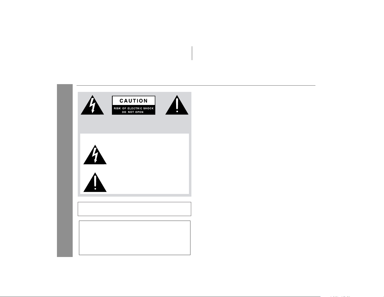
Explanation of Graphical Symbols:
The lightning flash with arrowhead symbol,
within an equilateral triangle, is intended to
alert the user to the presence of uninsulated
“dangerous voltage” within the product’ s enclosure that may be of sufficient magnitude
to constitute a risk of electric shock to persons.
The exclamation point within an equilateral
triangle is intended to alert the user to the
presence of important operating and maintenance (servicing) instructions in the literature accompanying the appliance.
WARNING: TO REDUCE THE RISK OF FIRE OR ELECTRIC
SHOCK, DO NOT EXPOSE THIS APPLIANCE TO RAIN OR
MOISTURE.
Note to CATV system installer:
This reminder is provided to call the CATV sys tem installer's at tention to Article 820-40 of the National Electrical Code that provides
guidelines for proper grounding and, in part icular, spec ifies that the
cable ground shall be connected to the grounding system of the
building, as close to the point of cable entry as practical.
NOTE
This equipment has been tested and found to comply with the limits for a
Class B digital device, pursuant to Part 15 of the FCC Rules. These
limits are designed to provide reasonable protection against harmful interference in a residential installation. This equipment generates, uses,
and can radiate radio frequency energy and, if not installed and used in
accordance with the instructions, may cause harmful interference to radio communications. However, there is no guarantee that interference
will not occur in a particular installation. If this equipment does cause
harmful interference to radio or television reception, which can be determined by turning the equipment off and on, the user is encouraged to try
to correct the interference by one or more of the following measures:
CAUTION:
THIS PRODUCT IS A CLASS 1 LASER PRODUCT.
USE OF CONTROLS OR ADJUSTMENTS OR PERFORMANCE OF
PROCEDURES OTHER THAN THOSE SPECIFIED HEREIN MAY
RESULT IN HAZARDOUS RADIATION EXPOSURE.
AS THE LASER BEAM USED IN THIS PRODUCT IS HARMFUL TO
THE EYES, DO NOT ATTEMPT TO DISASSEMBLE THE CABINET.
REFER SERVICING TO QUALIFIED PERSONNEL ONLY.
2
0501
Page 3

HT-X1 (U) TINSEA050SJZZ
IMPORTANT SAFETY INSTRUCTIONS
1 Read Instructi ons - All the saf ety and operating instru ctions sho uld
be read before the product is operated.
2 Retain Instructions - The safety and operating instructions should be
retained for future reference.
3 Heed Warnings - All warnin gs on the produc t and in the operat ing
instructions should be adhered to.
4 Follow Instru ctions - All operating and use instructi ons should be
followed.
5 Cleaning - Unplug thi s product from the wall outlet bef ore cleaning.
Do not use liquid cleane rs or aeroso l cle aners. Use a damp clo th for
cleaning.
6 Attachments - Do not use attachments not recommended by the prod-
uct manufacturer as they may cause hazards.
7 Water and Moisture - Do not use this product near wat er - for ex-
ample, near a bath tub , wash bow l, kitchen sin k, or laundr y tub; in a
wet basement; or near a swimming pool; and the like.
8 Accessories - Do not pla ce this product on an uns table cart, stand,
tripod, bracket, or table. The product may fall, causing serious injury to
a child or adult, and serious dam age to the pro duct. Use onl y with a
cart, stand, tripod , bracket, or table recommend ed by the manufacturer, or sold with the produc t. Any mounting of the product should
follow the manufacturer’s instructions, and should use a mounting accessory recommended by the manufacturer.
9 A product and cart combin ation should be moved wit h
care. Quick stops, excessive force, and uneven surfaces
may cause the product and cart combination to overturn.
10 Ventilation - Slots and openings in the cabinet are provided for venti-
lation and to ens ure reliable ope rat ion of the pro duct and to protec t it
from overheati ng, and these openin gs must not be blo cked or covered. The openings should never be blocked by placing the product on
a bed, sofa, rug, or other sim ilar surfac e. This product sho uld not be
placed in a built-in installation such as a bookcase or rack unless proper
ventilation is pro vided or the manufacturer ’s instructions hav e been
adhered to.
11 Power Sources - This product should be operated only from the type
of power source indicated on the marking label. If you are not sure of
the type of power supply to your home, consult your product dealer or
local power compan y. For produc ts intended to operat e from battery
power, or other sources, refer to the operating instructions.
12 Grounding or Pol arization - This product may be equipp ed with a
polarized alter nati ng- cur rent lin e plu g (a plu g hav ing one bla de wid er
than the other). Thi s plug will fit into the power outlet onl y one way.
This is a safety feature. If you are unable to insert the plug fully into the
outlet, try rev ersing the plug. If the plu g should still fai l to fit, contact
your electrician to replace your obsolete outlet. Do not defeat the safety
purpose of the polarized plug.
Alternate Warnings - This product is equipped with a three-wire
grounding-ty pe plug, a plu g having a thi rd (groundin g) pin. Thi s plug
will only fit into a grounding-type power outlet. This is a safety feature.
If you are unable to insert the plug into the outlet, contact your electrician to replace your obsolete outlet. Do not defeat the safety purpose
of the grounding-type plug.
13 Power-Cord Pro tection - Power-sup ply cords should be routed so
that they are not likely to be wal ked on or pinche d by items placed
upon or against the m, paying particular att ention to cords at plugs,
convenience receptacles, and the point where they exit from the product.
14 Protective Att achment Plug - The product is equ ipped with an at-
tachment plug having overload protection. This is a safety feature. See
Instruction Manual for replacement or resetting of protective device. If
replacement of the plug is required, be sure the service technician has
used a replaceme nt plug specif ied by the manufa cturer that has the
same overload protection as the original plug.
HT-X1
Important Instruction
0304
3
Page 4
HT-X1
IMPORTANT SAFETY INSTRUCTIONS
(continued)
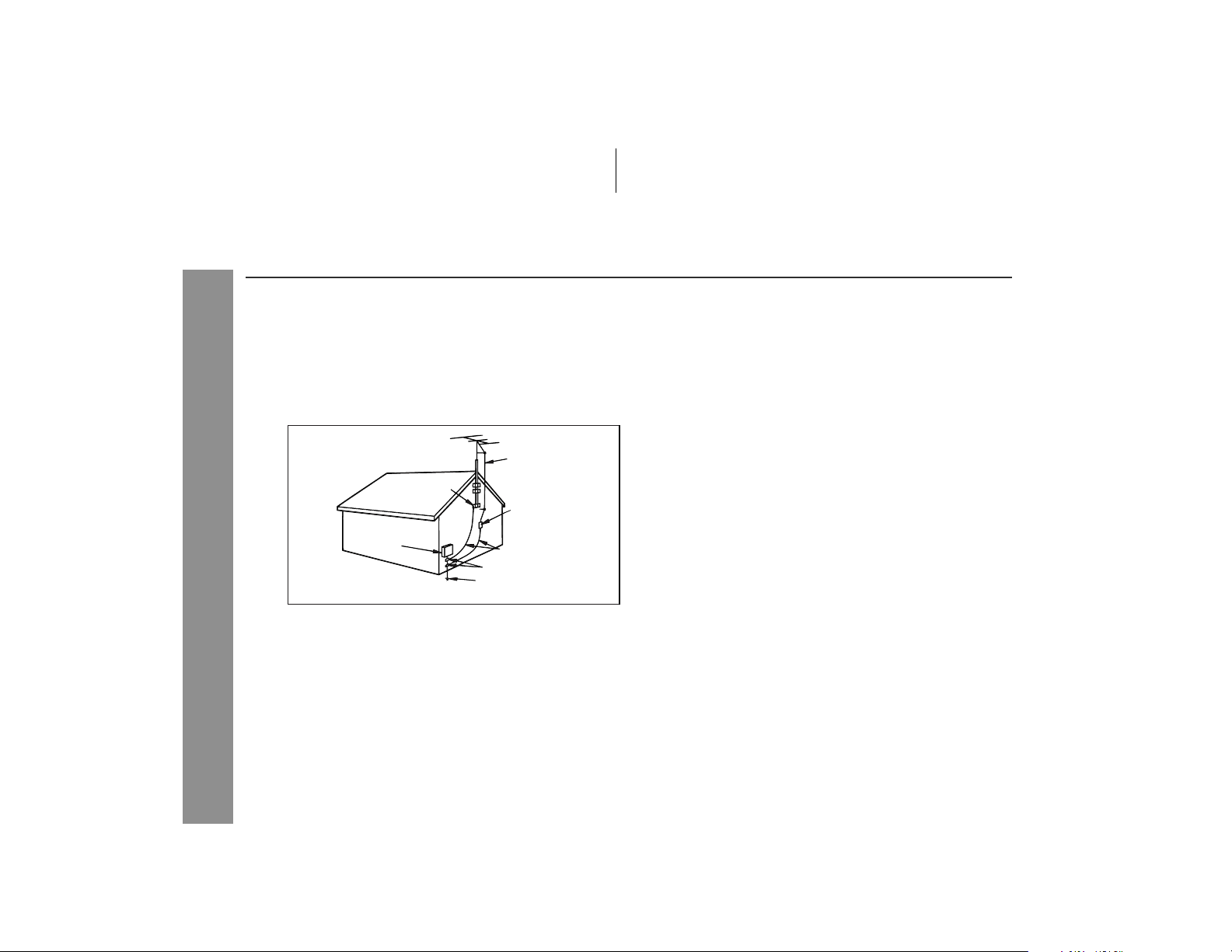
15 Outdoor Antenna Grounding - If an outside antenna or cable system
is connected to the produc t, be sure the antenn a or cable system is
grounded so as to provide some protection against voltage surges and
built-up static charges. Article 810 of the National Electrical Code, ANSI/
NFPA 70, provides information with regard to proper grounding of the
mast and supporting structure, grounding of the lead-in wire to an antenna discharge unit, size of grounding conductors, location of antenna
discharge unit, connection to grounding electrodes, and requirements
for the grounding electrode.
Example of antenna gr oundin g as per
National Electrical Code, ANSI /NFPA 70
GROUND
CLAMP
ELECTRIC
SERVICE
EQUIPMENT
NEC - NATIONAL ELECTRICAL CODE
S2898A
ANTEN NA LEAD IN WIRE
ANTEN NA DISCHARGE UNIT
(NEC SECTION 810-20)
GROUNDING CONDUCTORS
(NEC SECTION 810-21)
GROUND CLAMPS
POWER SERVICE GROUNDING
ELECTRODE SYSTEM
(NEC ART 250, PART H)
16 Lightning - For added protectio n for this produc t during a lightn ing
Important Instruction
storm, or when it is lef t unattended and unused for long periods of
time, unplug it from the wall outlet and disconnect the antenna or cable
system. This will pre vent dam age to the produc t due to lig htning and
power-line surges.
17 Power Lines - An outside antenna system should not be located in the
vicinity of overhead power lines or other electric light or power circuits,
or where it can fall into such power lines or circuits. When installing an
outside antenn a system, ext reme car e should be taken to kee p from
touching such power lin es or circuits as contac t with them might be
fatal.
18
Overloading - Do not overload wall out lets, ext ension cor ds, or integral
convenience receptacles as this can result in a risk of fire or electric shock.
Object and Liq uid Entry - Never pus h objects of any kind into thi s
19
product through openings as they may touch dangerous voltage points
or short-out parts that could result in a fire or electric shock. Never spill
liquid of any kind on the product.
20 Servicing - Do not attempt to service this product yourself as opening
or removing cov ers may expose you to dangerous vol tage or other
hazards. Refer all servicing to qualified service personnel.
21 Damage Requiring Service - Unplug this product from the wall outlet
and refer servic ing to qualif ied ser vice person nel und er the follow ing
conditions:
a) When the power-supply cord or plug is damaged,
b)If liquid has been spilled, or objects have fallen into the product,
c) If the product has been exposed to rain or water,
d)If the pro duct does not ope rate normally by fol lowing the operating
instructions . Adjust only tho se contro ls tha t are covere d by the operating instructions as an improper adjustment of other controls may
result in damage and will often require extensive work by a qualified
technician to restore the product to its normal operation,
e) If the product has been dropped or damaged in any way, and
f) When the product exh ibits a distin ct change in perfor mance - this
indicates a need for service.
22 Replacement Par ts - When rep laceme nt parts are requir ed, be sure
the service techni cian has used replaceme nt parts specified by the
manufacturer or have the same characterist ics as the original part.
Unauthorized substitution s may result in fire, ele ctric shock, or other
hazards.
23 Safety Check - Upon completion of any service or repairs to this prod-
uct, ask the ser vic e technician to perform safety che cks to det er mine
that the product is in proper operating condition.
24 Wall or Ceiling Mounting - The product should be mounted to a wall
or ceiling only as recommended by the manufacturer.
25 Heat - The produc t should be sit uated awa y from hea t source s such
as radiators, heat registers, stoves, or other products (including amplifiers) that produce heat.
0304
4
Page 5

HT-X1
"DTS" and "DTS Digital Surround" are registered trademarks of
Digital Theater Systems, Inc.
Manufactured under license from Dolby Laboratories.
"Dolby", "Pro Logic" and the double-D symbol are trademarks of
Dolby Laboratories.
NOTES
! Licensed under one or more of U.S. Pat. 4,972,484, 5,214,678,
5,323,396, 5,530,655, 5,539,829, 5,544,247, 5,606,618,
5,610,985, 5,740,317, 5,777,992, 5,878,080 or 5,960,037.
!
Supply of th is product does not conv ey a license n or imply any right
to distribu te co nte nt c rea ted with thi s pr od uct i n r eve nue- gener at in g
broadcast systems (terrestrial, satellite, cable an d/or other distribution channel s), r even ue-gene rati ng st reamin g appl icat ions ( via I nte rnet, intranets and/or other networks), other revenue-generating
content distribution systems (pay-audio or audio-on-demand applications and the li ke) or on reve nue- ge nera ti ng physi cal med ia (compact discs, digital versatile discs, semiconductor chips, hard drives,
memory cards an d t he like). An i ndependent lic ense for such us e is
required. For details, please visit http://mp3licensing.com
MPEG Layer-3 audio coding technology licensed from Fraunhofer
IIS and Thomson.
.
ENERGY STAR® Program Information
Products that have earned
the ENERGY STAR
designed to protect the
environment through
superior energy efficiency.
ENERGY STAR® is a U.S. registered mark.
®
are
0411
Copyright Information:
!
Unauthorized copying, broadcast, public display, transmission,
public perfor mance and rent al (regar dless of whet her or not s uch
activities are for profit) of disc contents are prohibit ed by law.
! This system is equipped with copy protection technology that
causes substantial degradation of images when the contents of
a disc are copied to a video tape.
Copy Protection:
This unit supports Macrovision copy protection.
On DVD discs that include a copy protection code, if the cont ents of
the DVD disc are copied using a VCR, the copy protection code prevents the videotape copy from playing normally.
Apparatus Claims of U.S. Patent Nos. 4,631,603, 4,577,216,
4,819,098 and 4,907,093 licensed for limited viewing uses only.
This product incorporates copyright protection technology that is
protected by method claims of certain U.S. patents and other
intellectual property rights owned by Macrovision Corporation
and other rights owners. Use of this copyright protection
technology must be authorized by Macrovision Corporation, and
is intended for home and other limited viewing uses only unless
otherwise authorized by Macrovision Corporation. Reverse
engineering or disassembly is prohibited.
0403E
NOTICE FOR PROGRESSIVE SCAN OUTPUTS:
CONSUMERS SHOULD NOTE THAT NOT A LL HIGH DEFINITION
TELEVISION SETS ARE FULLY COMPATIBLE WITH THIS PRODUCT AND MAY CAUSE ARTIF ACTS T O BE DIS PL AYED IN THE PIC TURE. IN CASE OF 525 OR 625 PROGRESSIVE SCAN PICTURE
PROBLEMS, IT IS RECOMMENDED THAT THE USER SWITCH THE
CONNECTION TO THE 'STANDARD DEFINITION' OUTPUT. IF
THERE ARE QUESTIONS REGARDING OUR TV SET COMPATIBILITY WITH THIS MODEL 525p AND 625p DVD PLAYER, PLEASE
CONTACT OUR CUSTOMER SERVICE CENTER.
Important Instruction
5
Page 6
HT-X1
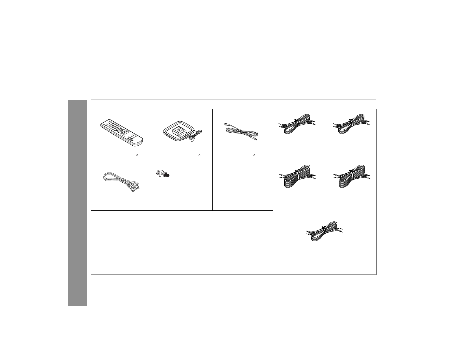
Accessories
Please confirm that the following accessories are included.
Remote control 1 AM loop antenna 1 FM antenna 1
(RRMCGA027SJZZ) (QANTL0008SJZZ) (QANTWA001SJZZ)
Video cable 1 AC power cord 1
(QCNWGA004SJZZ) (QACCU0003SJ00) (QCNWGA019SJZZ)
General Information
Pattern paper for main unit 1 Button name label 1 Speaker connection cord 5
(TCAUZA010SJZZ) (HDECPA003SJZZ) (QCNWGA008SJZZ)
Caution:
Do not use the supplied AC power cord for other equipment. Fi re or
electric shock may result.
Note:
Only the above accessories are included.
6
System connection cable 1
White
(for left front
speaker)
approx. 16 feet (5 m)
Blue
(for left surround
speaker)
approx. 49 feet (15 m)
(for center speaker)
approx. 16 feet (5 m)
Red
(for right front
speaker)
approx. 16 feet (5 m)
Gray
(for right surround
speaker)
approx. 49 feet (15 m)
Green
Page 7

Contents
HT-X1
Page
"
General Information
Precautions . . . . . . . . . . . . . . . . . . . . . . . . . . . . . . . . . . . . . . . . . 8
Description of discs . . . . . . . . . . . . . . . . . . . . . . . . . . . . . . . .9 - 11
Controls and indica t ors . . . . . . . . . . . . . . . . . . . . . . . . . . . . 1 2 - 16
"
Preparation for Use
System installa tion . . . . . . . . . . . . . . . . . . . . . . . . . . . . . . . . . . 17
Main unit prepar a t ion . . . . . . . . . . . . . . . . . . . . . . . . . . . . . . . . 18
System connection s . . . . . . . . . . . . . . . . . . . . . . . . . . . . . .19 - 25
Remote control . . . . . . . . . . . . . . . . . . . . . . . . . . . . . . . . . . . . . . 26
General contro l . . . . . . . . . . . . . . . . . . . . . . . . . . . . . . . . . . . . . 27
" DVD Operation
Playing a disc . . . . . . . . . . . . . . . . . . . . . . . . . . . . . . . . . . . .28 - 30
Basic operation
To locate the beginning of a chapter/track (skip) . . . . . . . . . . 31
Fast forward/Fast reverse (search) . . . . . . . . . . . . . . . . . . . . . 31
To start playback from the desired point (direct play) . . . . . . 32
Useful operation
To change the subtitle language . . . . . . . . . . . . . . . . . . . . . . . 33
To change the audio language (audio ou tp ut) . . . . . . . . . . . . 34
To brighten an ima ge . . . . . . . . . . . . . . . . . . . . . . . . . . . . . . . . . 34
To improve the image quality . . . . . . . . . . . . . . . . . . . . . . . . . . 35
To select a title from the top menu of the disc . . . . . . . . . . . . 3 6
To select a subtitle or audio language from the disc menu . . . . 36
Still picture/F r a me a dva nce . . . . . . . . . . . . . . . . . . . . . . . . . . . 36
Slow-motion pla y . . . . . . . . . . . . . . . . . . . . . . . . . . . . . . . . . . . . 36
To change the angl e . . . . . . . . . . . . . . . . . . . . . . . . . . . . . . . . . 37
To zoom in on an image (zoom) . . . . . . . . . . . . . . . . . . . . . . . . 37
To play in the desired order (programmed playback) . . . . . . 38
To play repeate dly (repeat play) . . . . . . . . . . . . . . . . . . . . . . . . 39
To play the contents between the specified points repeatedly
(A-B repeat) . . . . . . . . . . . . . . . . . . . . . . . . . . . . . . . . . . . . . . . . 40
To change the displa y on the main unit . . . . . . . . . . . . . . . . . 40
To change the display on TV screen . . . . . . . . . . . . . . . . . . . . 41
Page
"
Audio CD Operation
Playing an audio CD
To play in random order (random play) . . . . . . . . . . . . . . . . . . 42
To start playback from the desired point (direct play) . . . . . . 43
"
MP3, WMA and JPEG Disc Operation
Playing an MP3, WMA or JPEG disc . . . . . . . . . . . . . . . . . 44, 45
"
Radio
Listening to the r ad io . . . . . . . . . . . . . . . . . . . . . . . . . . . . . 46, 47
"
Advanced Features
Enjoying surround sound (s ound mode) . . . . . . . . . . . . .48 - 51
Changing the de f ault setting of the amplifier . . . . . . . . . .52 - 54
Changing the initial settin g of D VD . . . . . . . . . . . . . . . . . .55 - 58
Language code list for dis c language . . . . . . . . . . . . . . . . . . . 59
Sleep operati on . . . . . . . . . . . . . . . . . . . . . . . . . . . . . . . . . . . . . 60
Audio connecti on t o o th e r eq uipment . . . . . . . . . . . . . . . . . . . 61
To install the main unit on the wall . . . . . . . . . . . . . . . . . . . . . 62
"
References
Troubleshooti ng c ha r t . . . . . . . . . . . . . . . . . . . . . . . . . . . . . 63, 64
Maintenance . . . . . . . . . . . . . . . . . . . . . . . . . . . . . . . . . . . . . . . . 65
Error indicators and warnings . . . . . . . . . . . . . . . . . . . . . . . . . 65
Optional accessory . . . . . . . . . . . . . . . . . . . . . . . . . . . . . . . . . . 65
Specificati ons . . . . . . . . . . . . . . . . . . . . . . . . . . . . . . . . . . . 66, 67
CONSUMER LIMITED WARRANTY . . . . . . . . . . . . . .Back cover
General Information
7
Page 8
HT-X1
Precautions
"
General
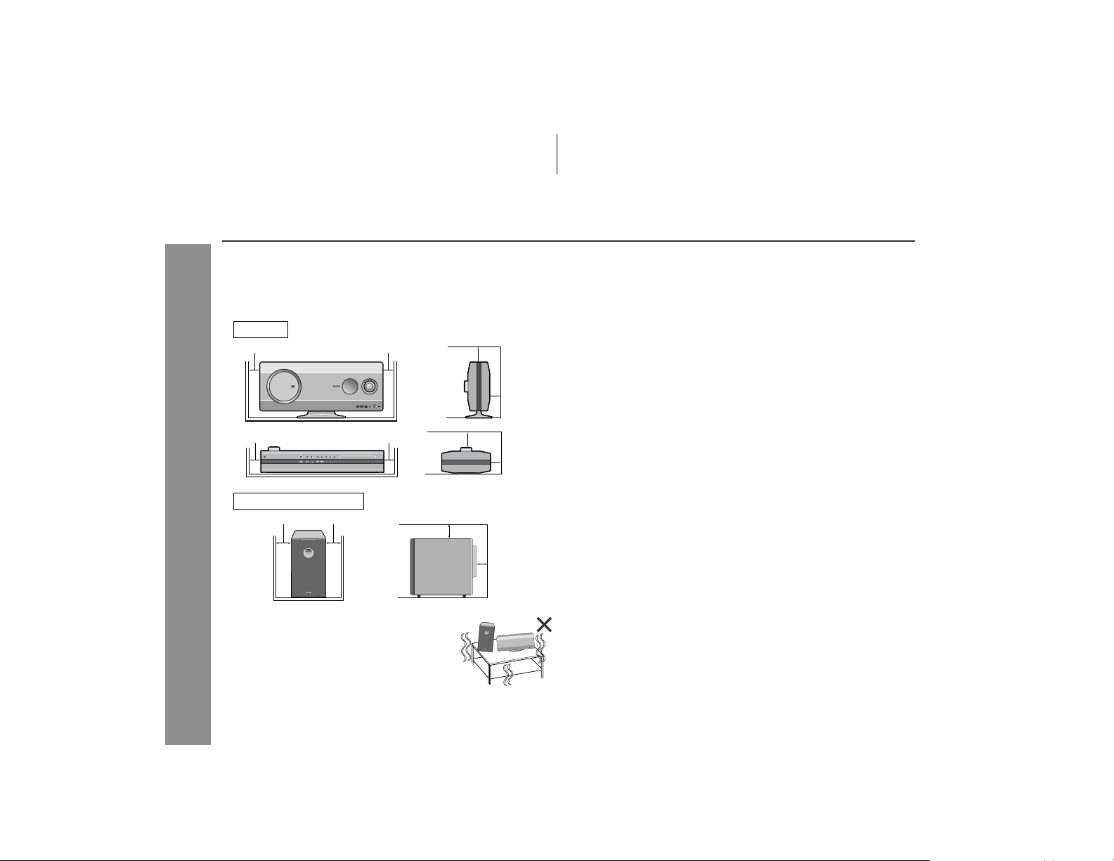
! Please ensure that the equi pment is positioned in a well-venti-
lated area and that there is at least 4" (10 cm) of free space along
the sides and back. There must also be a m inim um of 6" (15 cm)
of free space on the top of the unit.
Main unit
4" (10 cm) 4" (10 cm)
4" (10 cm) 4" (10 cm)
Subwoofer/amplifier unit
4" (10 cm) 4" (10 cm)
General Information
! Use the system on a firm, level surface free
from vibration.
6" (15 cm)
6" (15 cm)
6" (15 cm)
4" (10 cm)
! Do not place anything on top of the components.
! Do not expose the system to moisture, to temperatures higher
than 140°F (60°C) or to extremely low temperatures.
! If your system does not work properly, disconnect the A C power
cord from the AC outlet. Plug the AC power cord back in, and
then turn on your system.
4" (10 cm)
4" (10 cm)
! This sys tem should only be used within the range of 41°F - 95°F
(5°C - 35°C).
Warning:
The voltage used must be the same as that specified by this system. Using this product with a higher vol tage other than that spe cified is dangerous and may result i n a fire or other types of accident,
causing damage. SHARP will not be held responsible for any damage resulting from the use of this syst em with a voltage other than
that specified.
" Volume control
The sound level at a given volume setting d epends on speaker effi-
!
Keep the system away from direct sunlight, strong magnetic fields, excessive
dust, humidity and electronic/electrical
equipment (home computers, facsimiles,
8
etc.) which generates electrical noise.
ciency, location and various other f actors. It is advisable to avoid
exposure to high volume levels, which occurs while t urning the un it
on with the volume control setting up high, or whil e continually listening at high volumes.
Page 9

Description of discs
"
Types of playable discs
The unit can play back discs bearing any of the following marks:
DVD
DVD-Video Disc DVD-R DVD-RW DVD+R DVD+RW
for NTSC system for NTSC
system
Recorded in the vid-
Some DVD may not function as described in the manual. See
the disc jacket for restrictions.
for NTSC
system
for NTSC
system
for NTSC
system
HT-X1
General Information
! For unplayable discs, see page 11.
9
Page 10
HT-X1
Description of discs (continued)
"
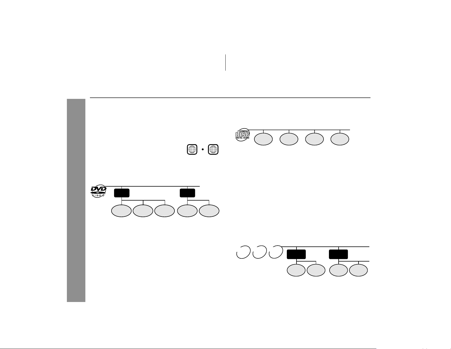
DVD-Video
A popular type of DVD disc of the same size as a CD, mainly containing video images.
Region num ber
DVD discs are programmed with region
numbers indicating countries in which
they can be played. This system can
play discs with region number "1" or
"ALL".
Title and chapter
DVD-Video discs are divided into " titles" and "chapters". If t he disc
has more than one movie on it, each movie is a separate "title".
"Chapters" are subdivisions of titles.
Title 1 Title 2
Chapter 1
General Information
" DVD-R/DVD-RW/DVD+R/DVD+RW
! You can play DVD-R/DVD-RW/DVD+R/DVD+RW discs recorded
in the video mode.
! Before playing DVD-R/DV D-RW/DVD+R/DVD+RW discs with
this unit, finalize them with the equipment used for recording.
Chapter 2 Chapter 3 Chapter 1 Chapter 2
Region number
(playable area number)
1
ALL
"
Audio CD
Track
The audio CD is composed of "tracks". Tracks are equivalent to
songs on a CD.
Track 1 Track 2 Track 3 Track 4
" MP3/WMA/JPEG format on CD-R/CD-RW
An MP3 file is audio data compressed in the MPEG 1 audio layer 3
format. MP3 files have the extension ".mp3". (Files with the extension ".mp3" may not play, or noise may occur during playb ack if not
recorded in the MP3 format.)
WMA is an audio file format developed by Microsoft wi th the ".wma"
extension. This type of audio file is recorded through Microsoft Wi ndows operating system.
A JPEG file is still image data compressed in the JPEG (Joint Photographic Experts Group) format. JPEG files have the extension
".jpg".
Folder and file
MP3/WMA/JPEG discs consist of "folders" and "files".
JPEG
WMA
MP3
disc
disc
disc
Folder 1
File 1
Folder 2
File 2 File 1
File 2
10
Page 11
HT-X1 (U) TINSEA050SJZZ
HT-X1
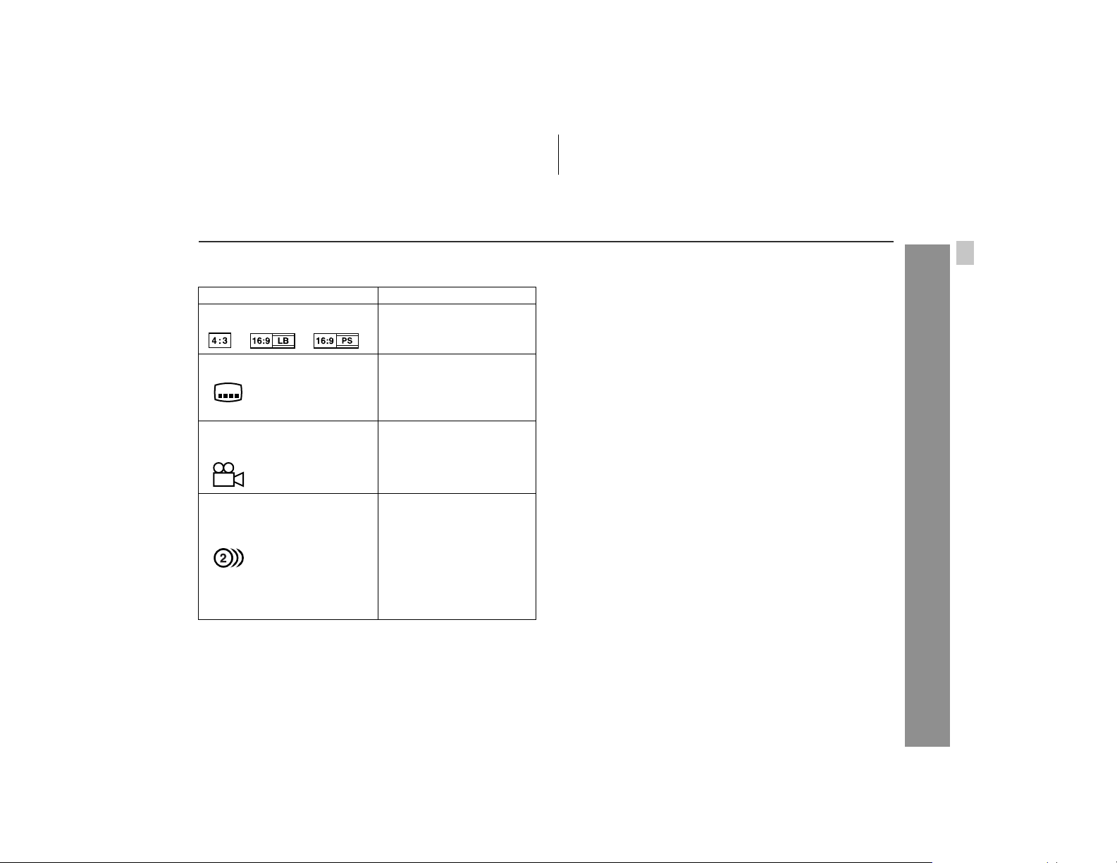
" Icons used on DVD discs
Check the icons of the DVD jacket before playing your discs.
Display Description
Format recorded on the DVD Select a type according to the
Type of subtitles recorded Recorded subtitle languages.
Example: You can select a subtitle lan-
2
1. English
2. German
Number of camera angles Number of angles recorded on
2
Number of audio tracks and audio recording systems
Example:
1: Original <English>
(Dolby Digital 5.1 Surround)
2. German (Dolby Digital 2 ch)
connected TV type.
guage.
the DVD.
You can view scenes from dif-
ferent angles.
The number of audio tracks
and audio recording systems
are indicated.
! You can change the audio
language.
! Audio and recording sys -
tem vary depending on the
DVD. Check them in the
DVD's manual.
" Discs that cannot be played
! DVDs without the region num-
ber "1" or "ALL".
DVDs with PAL system
!
! DVDs with SECAM system ! Photo CD
! DVDs with MPEG sound ! CD-ROM
DVD-ROM
!
! DVD-RAM ! Discs recorded in special for-
Notes:
! The discs above cannot be played at all, or no sound is heard
although images appear on the screen or vice versa.
! Faulty playback may damage the speakers and can have an
adverse effect on your hearing when played at high volume settings.
! This DVD player adopts the NTSC system. Discs that were
made in foreign countries may not be played back. Check
the recording system before purchasing discs.
! You cannot play illegally produced discs.
! A disc with scratches or fingerpri nts may not play properl y. Refer
to "Care of discs" (page 65) and clean the disc.
! DVD-Audio
CDG
!
Super video CD/Video CD
!
SACD
!
mats, etc.
General Information
11
Page 12
HT-X1
Controls and indicators
9
10
General Information
1 2 3 4 5 6 7 8
Display
11
12
13
11
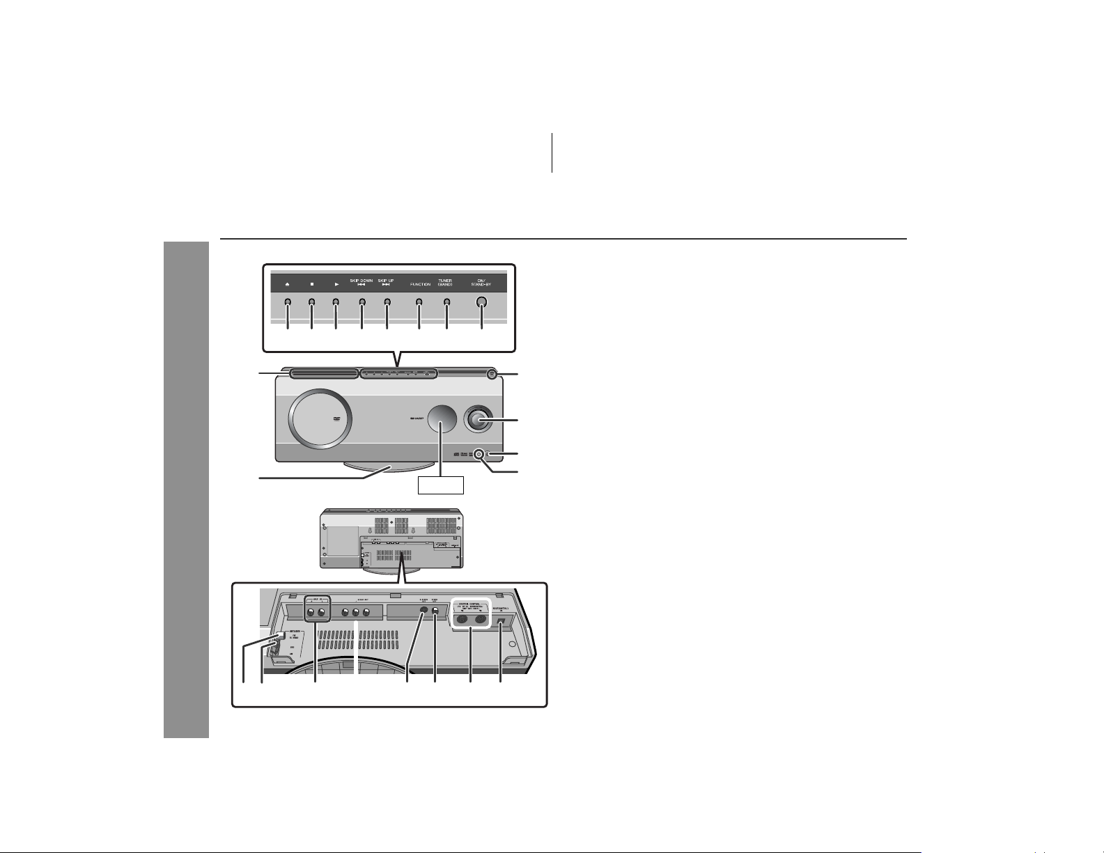
" Top and front panel
Reference page
1.Disc Eject Button . . . . . . . . . . . . . . . . . . . . . . . . . . . . . . . . . 29
2.Stop Button . . . . . . . . . . . . . . . . . . . . . . . . . . . . . . . . . . . 28, 29
3.Play Button . . . . . . . . . . . . . . . . . . . . . . . . . . . . . . . . . . . . . . 29
4.Chapter (Track) Skip Down or Fast Reverse Button . . . . . 31
5.Chapter (Track) Skip Up or Fast Forward Button . . . . . . . 31
6.Function Selector Button . . . . . . . . . . . . . . . . . . . . . . . . . . . 49
7.Tuner (Band) Button . . . . . . . . . . . . . . . . . . . . . . . . . . . . . . 46
8.On/Stand-by Butto n . . . . . . . . . . . . . . . . . . . . . . . . . . . . . . . 25
9.Disc Compartment . . . . . . . . . . . . . . . . . . . . . . . . . . . . . . . . 28
10.Main Unit Stand . . . . . . . . . . . . . . . . . . . . . . . . . . . . . . . . . . 18
11.Remote Sensor . . . . . . . . . . . . . . . . . . . . . . . . . . . . . . . . . . . 26
12.Volume Control . . . . . . . . . . . . . . . . . . . . . . . . . . . . . . . . . . . 27
13.Headphone Jack . . . . . . . . . . . . . . . . . . . . . . . . . . . . . . . . . . 24
" Rear panel
Reference page
1.FM 75 Ohm Antenna Jack . . . . . . . . . . . . . . . . . . . . . . . 19, 20
2.Antenna Ground Terminal . . . . . . . . . . . . . . . . . . . . . . . 19, 20
3.AM Antenna Terminal . . . . . . . . . . . . . . . . . . . . . . . . . . 19, 20
4.Auxiliary (Audio Signal) Input Jacks. . . . . . . . . . . . . . . . . . 61
5.Component Video Output Jacks . . . . . . . . . . . . . . . . . . . . . 23
6.S-video Output Jack . . . . . . . . . . . . . . . . . . . . . . . . . . . . . . . 23
7.Video Output Jack . . . . . . . . . . . . . . . . . . . . . . . . . . . . . . . . 22
8.System Connection Jacks
(to subwoofer/amplifier unit) . . . . . . . . . . . . . . . . . . . . . 19, 20
9.Optical Digital Audio Input Jack . . . . . . . . . . . . . . . . . . . . . 61
12
21 34 5 76 8
Page 13
HT-X1
10
11
12
13
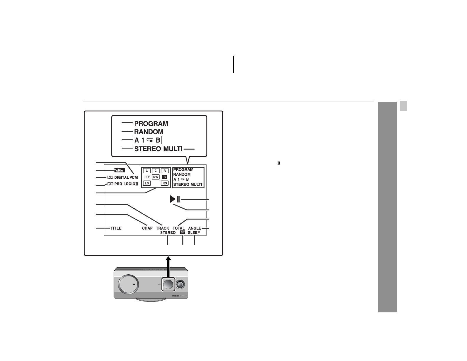
" Display
1
2
3
4
5
6
7
8
9
14
15
16
1.Program Indicator . . . . . . . . . . . . . . . . . . . . . . . . . . . . . 38, 47
2.Random Play Indicator . . . . . . . . . . . . . . . . . . . . . . . . . . . . 42
3.Repeat/One Track Repeat/A - B Repeat Indicators . . . 39, 40
4.2 channel Stereo Sound Mode Indicator . . . . . . . . . . . . . . 50
5.Multi Channel Sound Mode Indicato r . . . . . . . . . . . . . . . . . 51
6.PCM Signal Indicator . . . . . . . . . . . . . . . . . . . . . . . . . . . . . . 48
7.DTS Signal Indicator . . . . . . . . . . . . . . . . . . . . . . . . . . . . . . 48
8.Dolby Digital Signal Indicator . . . . . . . . . . . . . . . . . . . . . . . 48
9.Dolby Pro Logic Indicator . . . . . . . . . . . . . . . . . . . . . . . . 48
10.Audio Signal/Speaker Indicators . . . . . . . . . . . . . . . . . . . . 49
11.Track Indicator . . . . . . . . . . . . . . . . . . . . . . . . . . . . . . . . . . . 40
12.Chapter Indicator . . . . . . . . . . . . . . . . . . . . . . . . . . . . . . . . . 40
13.Title Indicator . . . . . . . . . . . . . . . . . . . . . . . . . . . . . . . . . . . . 40
14.Pause Indicator . . . . . . . . . . . . . . . . . . . . . . . . . . . . . . . . . . 29
15.Play Indicator . . . . . . . . . . . . . . . . . . . . . . . . . . . . . . . . . . . . 29
16.Total Indicator . . . . . . . . . . . . . . . . . . . . . . . . . . . . . . . . . . . 40
17.Angle Indicator . . . . . . . . . . . . . . . . . . . . . . . . . . . . . . . . . . . 37
18.FM Stereo Mode Indicator . . . . . . . . . . . . . . . . . . . . . . . . . . 46
19.FM Stereo Receiving Indicator . . . . . . . . . . . . . . . . . . . . . . 46
20.Sleep Indicator . . . . . . . . . . . . . . . . . . . . . . . . . . . . . . . . . . . 60
Reference page
17
General Information
18 19 20
13
Page 14
HT-X1
Controls and indicators (continued)
General Information
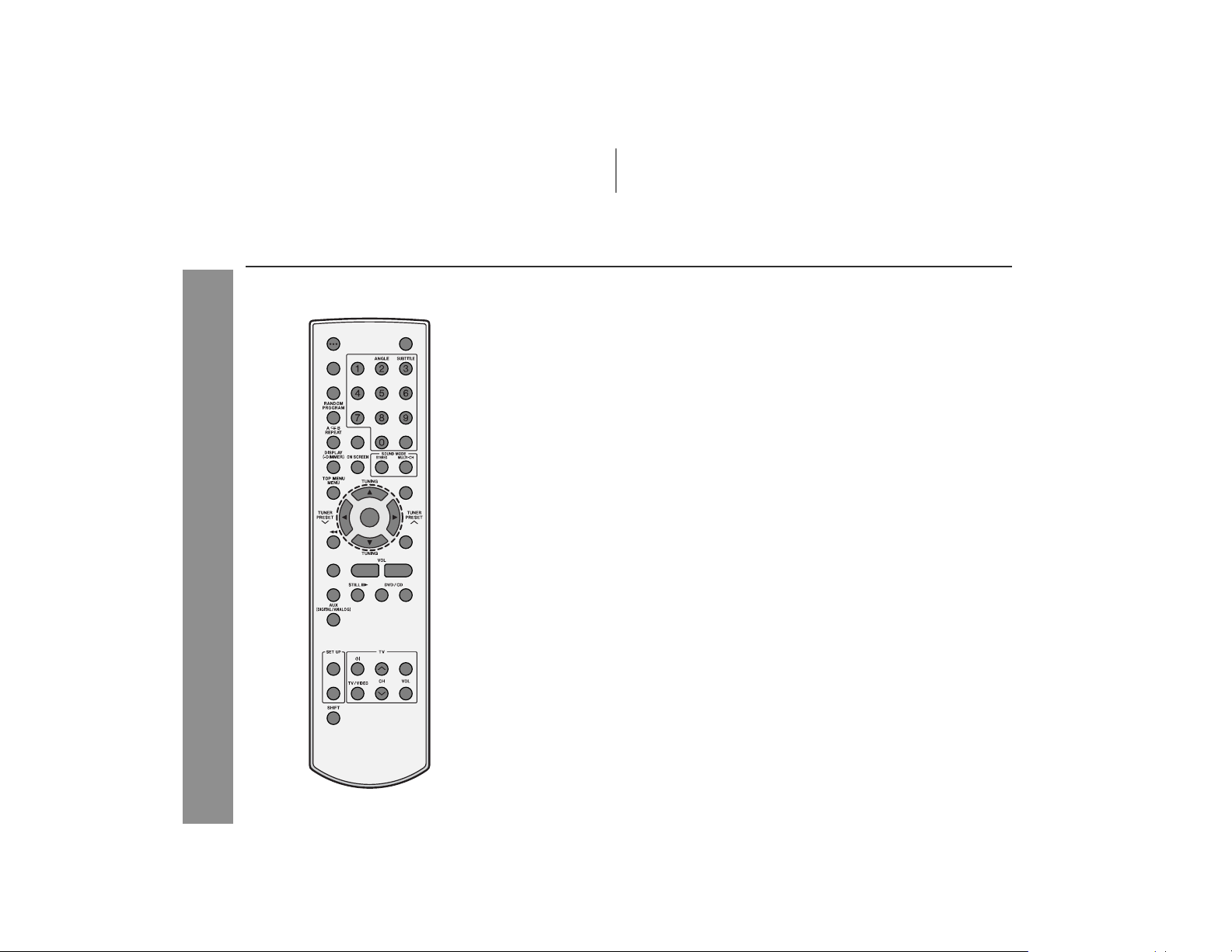
" Remote control
Reference page
1.Remote Control Transmitter . . . . . . . . . . . . . . . . . . . . . . . . 26
2.Direct Number Buttons . . . . . . . . . . . . . . . . . . . . . . . . . . . . 32
3.On/Stand-by Butto n . . . . . . . . . . . . . . . . . . . . . . . . . . . . . . . 26
4.Sleep Button . . . . . . . . . . . . . . . . . . . . . . . . . . . . . . . . . . . . . 60
5.Clear Button . . . . . . . . . . . . . . . . . . . . . . . . . . . . . . . . . . . . . 38
6.Random or Program Button . . . . . . . . . . . . . . . . . . . . . 38, 42
7.A - B Repeat or Repeat Button . . . . . . . . . . . . . . . . . . . 39, 40
8.Unit Display Select or Dimmer B ut t on . . . . . . . . . . . . . 27, 40
9.On Screen Display On/Off Bu t t on . . . . . . . . . . . . . . . . . . . . 41
10.Top Menu or Menu Button . . . . . . . . . . . . . . . . . . . . . . . . . . 36
11.Chapter (Track) Skip Down or Fast Reverse Button . . . . . 31
12.Disc Eject Button . . . . . . . . . . . . . . . . . . . . . . . . . . . . . . . . . 29
13.Multi Channel Selec t Button . . . . . . . . . . . . . . . . . . . . . . . . 51
14.Return Button . . . . . . . . . . . . . . . . . . . . . . . . . . . . . . . . . 52, 55
15.Stereo (2 channel) Select Button . . . . . . . . . . . . . . . . . . . . 50
16.Chapter (Track) Skip Up or Fast Forward Button . . . . . . . 31
17.Angle Button . . . . . . . . . . . . . . . . . . . . . . . . . . . . . . . . . . . . . 37
18.DVD Audio Language Select or
CD Audio Output Select Button . . . . . . . . . . . . . . . . . . . . . 34
19.Gamma Button . . . . . . . . . . . . . . . . . . . . . . . . . . . . . . . . . . . 34
20.Direct Button . . . . . . . . . . . . . . . . . . . . . . . . . . . . . . . . . . . . . 32
21.Subtitle Button . . . . . . . . . . . . . . . . . . . . . . . . . . . . . . . . . . . 33
22.Super Picture Button . . . . . . . . . . . . . . . . . . . . . . . . . . . . . . 35
23.Zoom Button . . . . . . . . . . . . . . . . . . . . . . . . . . . . . . . . . . . . . 37
24.Progressive Scan Mode Select Button . . . . . . . . . . . . . . . . 22
25.Tuner Preset Down or Cursor Button . . . . . . . . . . . . . . 37, 47
26.Tuning Up or Cursor Button . . . . . . . . . . . . . . . . . . . . . 37, 46
27.Tuner Preset Up or Cursor Button . . . . . . . . . . . . . . . . 37, 47
28.Tuning Down or Cursor Button . . . . . . . . . . . . . . . . . . . 37, 46
29.Enter Button . . . . . . . . . . . . . . . . . . . . . . . . . . . . . . . . . . . . . 32
14
Page 15
HT-X1
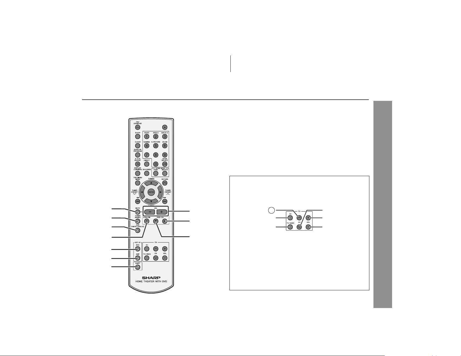
" Remote control
1.Mute Button . . . . . . . . . . . . . . . . . . . . . . . . . . . . . . . . . . . . . 27
2.Tuner (Band) Button . . . . . . . . . . . . . . . . . . . . . . . . . . . . . . 46
3.Auxiliary Button . . . . . . . . . . . . . . . . . . . . . . . . . . . . . . . . . . 61
4.Frame Advance or Pause Button . . . . . . . . . . . . . . . . . 29, 36
5.DVD Initial Setting Button . . . . . . . . . . . . . . . . . . . . . . . . . . 55
6.Amplifier Init ia l Setting Button . . . . . . . . . . . . . . . . . . . . . . 50
7.Shift Button . . . . . . . . . . . . . . . . . . . . . . . . . . . . . . . . . . . . . 33
8.Volume Up and Down Buttons . . . . . . . . . . . . . . . . . . . . . . 27
9.Play Button . . . . . . . . . . . . . . . . . . . . . . . . . . . . . . . . . . . . . . 29
10.Stop Button . . . . . . . . . . . . . . . . . . . . . . . . . . . . . . . . . . 28, 29
TV Operation Buttons
You can operate some functions of SHARP's TVs with the remote
control of this system.
However, some models cannot be operated.
1
2
8
9
1
2
Reference page
3
4
10
5
6
7
TV Channel Up Button TV Channel Down Button
Switches the TV channel up. Switches the TV channel
TV On/Stand-by Button TV Volume Up Button
Sets the TV power to "ON" or
"STAND-BY".
TV/VCR Input Select Button
Switches the input to TV or
VCR.
down.
Turns up the TV volume.
TV Volume Down Button
Turns down the TV volume.
General Information
15
Page 16
HT-X1
Controls and indicators (continued)
General Information
1
2
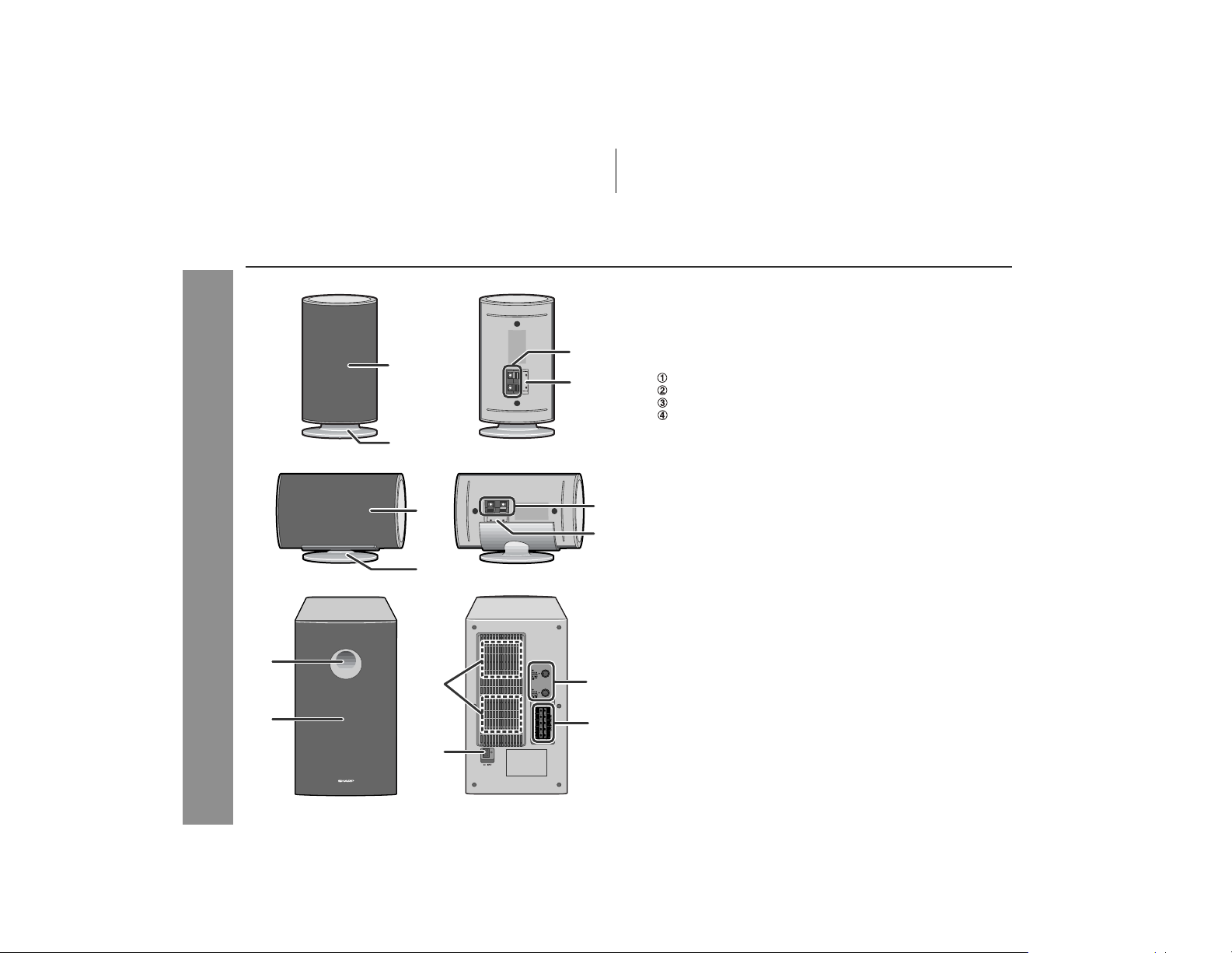
" Front/surround speakers
1.Speaker
2.Speaker Stand . . . . . . . . . . . . . . . . . . . . . . . . . . . . . . . . . . . 21
1
3
4
3.Speaker Terminals . . . . . . . . . . . . . . . . . . . . . . . . . . . . . 19, 21
4.Color Label
White ... Left Front Speaker
Red ... Right Front Speaker
Blue ... Left Surround Speaker
Gray ... Ri ght Surr ound Speaker
Reference page
2
" Center speaker
1
3
4
1.Speaker
2.Speaker Stand
3.Speaker Terminals . . . . . . . . . . . . . . . . . . . . . . . . . . . . . 19, 21
4.Color Label: Green
Reference page
2
" Subwoofer/amplifier unit
1.Bass Reflex Duct
2.Woofer
3.Cooling Fan . . . . . . . . . . . . . . . . . . . . . . . . . . . . . . . . . . . . . . 25
3
5
4.AC Power Input Jack . . . . . . . . . . . . . . . . . . . . . . . . . . . . . . 25
5.System Connection Jacks (to main unit) . . . . . . . . . . . 19, 20
6.Speaker Terminals . . . . . . . . . . . . . . . . . . . . . . . . . . . . . 19, 21
Reference page
6
16
4
Page 17
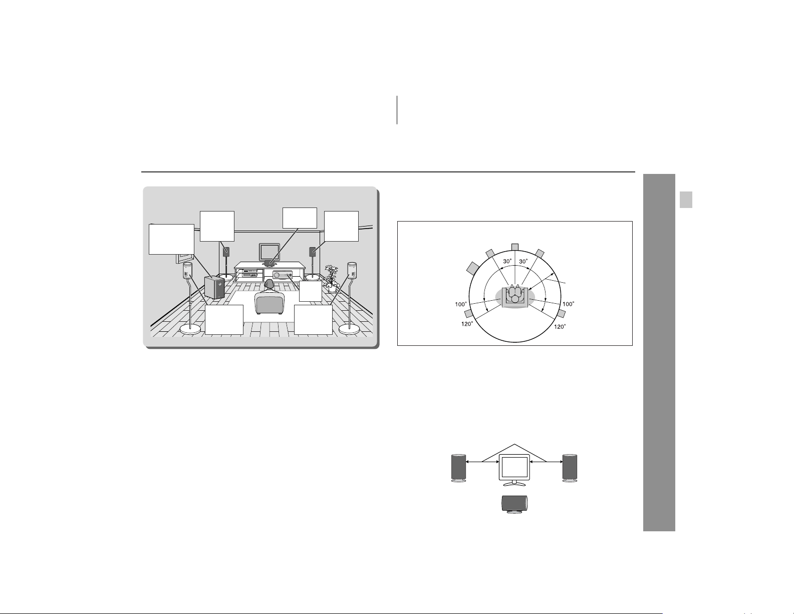
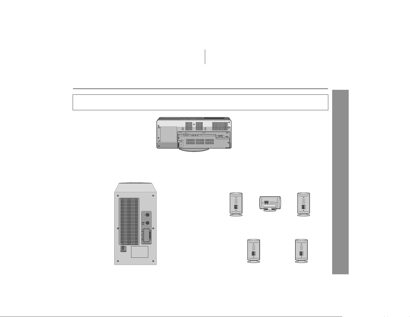
System installation
Installation image (with optional accessories):
Front
Subwoofer/
amplifier
unit
speaker
(left)
Surround
speaker
(left)
" Magnetically shielded speakers
The front and center speakers may be placed beside or near the TV
as they are magnetically shielded. However, color variation may
occur, depending on the type of the TV.
If color variation occurs...
Turn off the TV (from the power switch).
After 15 - 30 minutes, turn the TV on again.
If the color variation is still present...
Move the speakers further away from the TV.
Refer to the user's manual of the TV for details.
Center
speaker
Main
unit
Surround
speaker
(right)
Front
speaker
(right)
" Placing the speaker system
The best surround effect will be achieved by placing each
speaker at the same distance from the listening position.
It is recommended to arrange the speakers as shown below.
Center
Front speaker (left)
Subwoofer/
amplifier unit
Surround
speaker (left)
Notes:
!
The default distance is set to 6 feet (2 m). If speakers cannot be placed
at equal distances, refer to "Speaker delay setting" (see page 53).
Place the TV halfway between the front speakers.
!
! It is recommen ded that the center speaker be placed near the
television.
Place the surround speakers at a position just above the height of
!
your ears.
!
Place the su bw oofer/amplifier unit o n a s turdy and sta ble surface as
it tends to vibrate while reproducing bass sounds.
speaker
Same distance
Front speaker (right)
Default setting:
6 feet (2 m)
Surround
speaker (right)
HT-X1
Preparation for Use
Note:
The surround speakers and subwoofer/amplifier unit are not magnetically shielded.
Front speaker
(left)
Front speaker
(right)
Center speaker
17
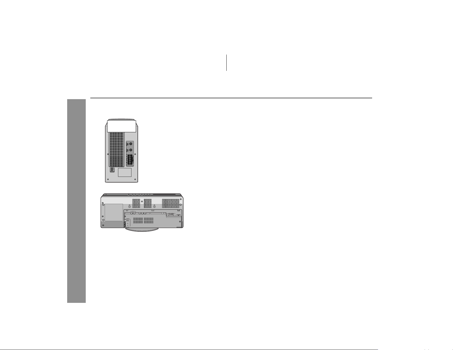
Page 18

HT-X1
Preparation for Use
Main unit preparation
18
Page 19
System connections
Make sure to disconnect the AC power cord from the wall outlet before you connect/disconnect cables to/from jacks inside the
!
back cover of the main unit or jacks of the subwoofer/amplifier unit.
! After connecting cables, attach the back cover and operate the main unit.
HT-X1
Preparation for Use
19
Page 20
HT-X1
System connections (continued)
" Connecting the system connection cable
Connect the main unit and subwoofer/amplifier unit as follows.
Subwoofer/
amplifier unit
Preparation for Use
" Antenna connection
Note:
Placing the antenna on the system or near the AC power c ord may
cause noise pickup. Place the antenna away from the system f or
better reception.
Installing the AM loop antenna:
Outdoor FM or AM antenna:
Use an outdoor FM or AM antenna if you require better reception.
Consult your dealer.
When using an outdoor AM antenna, be sure to keep the wire of the
AM loop antenna connected.
20
Page 21
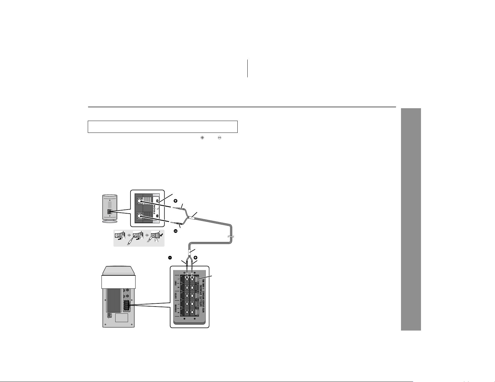
HT-X1
" Speaker connection
Make sure to leave the AC power cord disconnected when
connecting the speakers.
To prevent accidental short-circuits between and terminals, connect the speaker wires to the speakers first and then
to the subwoofer/amplifier unit.
When connecting speakers, match the colors of the back label
on the speaker, to the tube for the speaker wire, and speaker
terminal of the subwoofer/amplifi er unit.
1 Connect the wires to the speakers.
Example: To connect the left front speaker.
Label (white)
Red
Tube (white)
Black
2 Connect the other end to the
subwoofer/amplifier unit.
Subwoofer/
amplifier unit
Black
Tube (white)
Red
Speaker
terminal
(white)
Caution:
! The supplied speakers are excl usively for the HT-X1. Do not
connect them to other equipment, and do not connect other
speakers to the HT-X1. It may cause malfunction.
Do not mistake the and , and right and left terminals of t he
!
speaker wires. (The right speaker is placed on the right when you
face the subwoofer/amplifier unit.)
Do not stand or sit on the speakers. You may be injured.
!
Do not allow any objects to fall into or to be placed in th e bass
!
reflex ducts of the subwoofer/amplifier unit.
" Attaching the optional floor speaker stand
The front speakers and surround speakers support the optional floor
speaker stand (see page 65). Remove the origi nal stand for each
speaker using a screwdriver first. For details, refer to the manual for
the floor speaker stand.
Preparation for Use
Note:
Keep the removed speaker stands or screw in a safe place.
21
Page 22

HT-X1
Preparation for Use
System connections (continued)
" TV connection
Three types of jacks (VIDEO OUT, S-VIDEO OUT and COMPONENT VIDEO OUT) are available for connection of a TV and the
main unit. Connect according to your TV.
Connecting to a TV with a video input jack:
You can enjoy DVD images by connecting your TV and the main
unit with the supplied video cable.
Set the video mode to "Interlace" (default setting). For the procedure, refer to "Changing the video output mode".
What is progressive scanning?
The conventional TV system displays 30 frames of still images per
second to complete sequential movement (interlaced scanning).
Whereas, progressive scanning displays one frame every 1/60th of
a second (60 frames per second) to realize less-flicker, high-density
images.
22
Notes:
! Change the TV input in accordance with the connected jack.
Do not connect other equipment (VCR, etc.) between the TV and
!
the main unit. Images may be distorted.
! Refer to the operation manual of the equipment to be connected.
! Insert the plugs fully to avoid fuzzy pictures or noise.
Page 23

HT-X1
Connecting to a TV with an S-video input jack:
If your TV is equipped with an S-video input jack, you can enjoy
higher quality images by connecti ng it with an S-video cable (not
supplied).
Set the video mode to "Interlace" (default setting). For the procedure, refer to "Changing the video output mode" on page 22.
Note:
When the video and S-video cables are both connected, the images
from the S-video input jack appears on your TV.
Connecting to a TV with component video input jacks:
If your TV is equipped with component video input jacks, purchase a
component video cable to enjoy higher quality images.
Preparation for Use
Notes:
! If your TV has different indications for the component video
inputs (Y, CB and CR or Y, B-Y and P-Y), connect jac ks with its
matching color.
! Some component video jacks designed for the high-vision sy s-
tem are not compatible with DVD. Do not connect this unit to
those component video input jacks. (Images may appear distorted or may not appear due to the system difference.)
23
Page 24

HT-X1
System connections (continued)
" Attaching the back cover
After making all the connections, attach the back cover to the main
unit. Fit the claws into the holes.
Preparation for Use
" Headphones
! Before plugging in or unplugging the headphones, reduce the
volume.
! Be s ure your headphones have a 1/8" (3.5 mm) diameter pl ug
and impedance between 16 and 50 ohms. Th e recommended
impedance is 32 ohms.
! Pluggi ng in the headphones disconnects the speakers automati-
cally. Adjust the volume using the VOLUME control.
24
Page 25
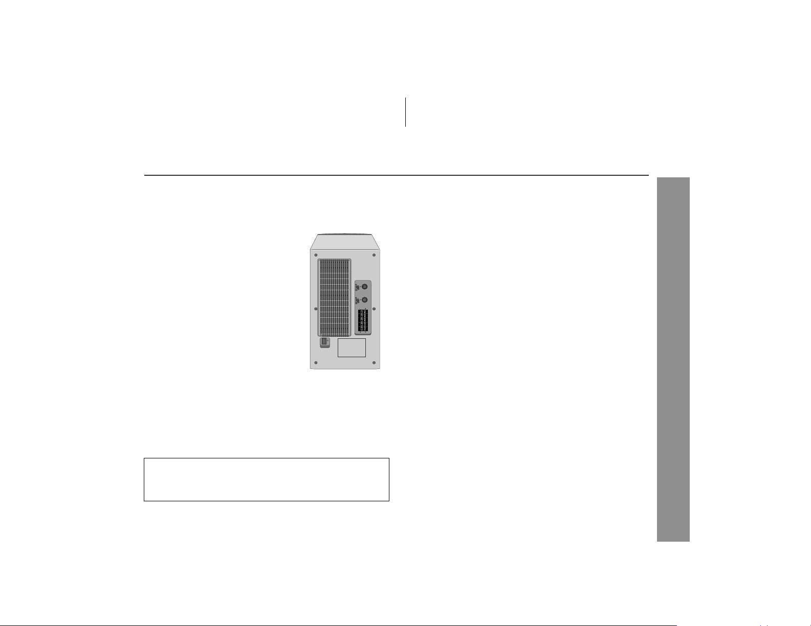
HT-X1
" Connecting the AC power cord
After checking all the connections have been made correctly, plug
the AC power cord to the AC power i nput jack of the subwoofer/
amplifier unit, and then to the AC outlet.
Notes:
! Ne ver use a power cord other t han the one supplied. Ot herwise,
a malfunction or an accident may occur.
! Un plug the AC power cord from the wall outlet if the subwoofer/
amplifier unit will not be in use for a prolonged period of time.
Cooling fan:
A cooling fan is built into this subwoofer/amplifier unit for better heat
radiation. Do not cover the opening in this section with any obstacles to avoid damage to the subwoofer/amplifier unit.
" To turn the power on
Press the ON/STAND-BY button.
If the power does not turn on, check if the AC power cord and system connection cable are plugged in properly.
To set the system to stand-by mode:
Press the ON/STAND-BY button again.
Note:
After the system enters the pow er stand-by mode, wait a few se conds to turn on again.
Preparation for Use
25
Page 26

HT-X1
Remote control
" Battery installation
Use 2 "AAA" size batteries (UM-4, R03, HP-16 or similar).
Batteries are not included.
1 Remove the battery cover.
2 Insert the batteries according to the direction indicated in
the battery compartment.
When inserting or removing the batteries, push them toward the
battery terminals.
3 Replace the cover.
Precautions for battery use:
Preparation for Use
Replace all old batteries with new ones at the same time.
!
Do not mix old and new batteries.
!
Remove the batteries if the system will not be used for long peri-
!
ods of time. This will prevent potential damage due to battery
leakage.
Caution:
Do not use rechargeable batteries (nickel-cadmium battery, etc.).
!
Installing the batteries incorr ectly may cause the system to m al-
!
function.
Notes concerning use:
! Replace the batteries if the operating distance is reduced or if the
operation becomes erratic.
! Periodi cally clean the transmitter on the remot e control and the
sensor on the main unit with a soft cloth.
! Exposing the sensor on the main unit to strong light may interfere
with operation. Change the lighting or the direction of the main
unit if this occurs.
! Keep t he remote control away from moisture, heat, shock, and
vibrations.
" Test of the remote control
Check the remote control after checking all the connections (see
pages 19 - 25).
Point the remote control directly at the remote sensor on the ma in
unit.
The remote control can be used within the range shown below:
Press the ON/STAND-BY button. Does the power turn on? Now,
you can enjoy music.
! The main unit is equipped with 2 remote sensors. Use them
according to the installation method as shown below.
26
Battery removal:
Remove the battery cover. Push each battery toward t he battery
terminal and take them out.
Page 27

HT-X1 (U) TINSEA050SJZZ
General control
" Volume control
Main unit operation:
When the VOLUME control is turned
clockwise, the volume will increase.
When it is turned counterclockwise,
the volume will decrease .
Remote control operation:
Press the VOL (+ or -) button to increase or decrease the volume.
0 1 10
......
39 40
" Muting
The volume is muted temporarily
when pressing the MUTE button.
! Press again to restore the vol-
ume.
The mute status is canceled
!
when you adjust the volume.
" To change the display brightness (2 levels)
Hold the DISPLAY/(-DIMMER) button down for 3 seconds or more.
Each time you press, brightness changes.
Dimmed
(*)
Brightened
HT-X1
Preparation for Use
(*) After approx. 5 seconds of DVD playback, the display dims and
the original brightness returns when you stop playback. The
brightness remains unchanged during playback of other media.
27
Page 28
HT-X1
Playing a dis c
Turn on the TV, and switch the input to the "VIDEO 1" or "VIDEO 2",
etc. accordingly.
DVD Operation
28
Page 29

HT-X1
4
If playback does not start, press the (DVD/CD ) button.
The sound mode in use appears during DVD playback.
Play indicator
Chapter or track number
When the menu appears on the TV screen:
On DVD, select an item by using the cursor ( , , or ) button
and press the ENTER button.
To interrupt playback:
Press the STILL button on the remote control.
To resume playback from the same point, press
the DVD/CD button.
To stop playback:
DVD:
Press the button twice.
CD/MP3/WMA/JPEG:
Press the button.
Playing time
Caution w he n inserting disc:
! Do not touch the playback side.
! Do not insert two or more discs in the disc insertion slot.
! Discs with labels, stickers or glue attached
may cause damage to the main unit.
! Do not use discs of special shapes (heart, oc-
tagon, etc.) or 3" (8 cm) discs with an adaptor.
Malfunction may result.
! A disc with scratches or fingerprints may not play properly. Re-
fer to "Care of discs (page 65)" and clean the disc.
! Insert or remove the disc st rai ght. Otherwise,
damage may result.
To remove the disc:
1. In the stop mode, press the button.
2. Remove the disc.
Disc
DVD Operation
29
Page 30

HT-X1
Playing a disc (continued)
Notes:
! When you turn on the power or switch the input to "DVD" initial-
ization starts and operation is not possible for a few seconds.
! Stop positions m ay be recorded on some discs. When you play
such a disc, playback stops there.
! During an operation, " " may appear indicating that the opera-
tion is disabled by the disc.
! Some DVD may not function as described in the manual. See the
disc jacket for restrictions.
! Some CD-R/CD -RW may not play properly due to the status of
the disc or equipment used for recording. Change the recordin g
speed or disc. For more details, see the manual for the equipment.
! Sound may skip at high vol ume depending on the disc. In this
case, turn down the volume.
Caution:
! Be careful not to damage the disc when inserting or removing it.
! A disc does not play if damaged, dirty or loaded upside down.
! Make sure to remo ve the disc before transporting th e main unit.
Otherwise the disc inside may cause malfunction.
! Do not l et coins, clips, etc. get i nto the disc insertion slot. Mal-
function may occur.
! When attempting to play discs with scratches or of a different
DVD Operation
region number, or unplayable or restricted (*1) di scs, an error
message will appear on the TV display and the disc will not play.
(*1)Viewing is prohibited on some DVDs according to the audi-
ence age.
" To resume playback after stopping (resume
play)
You can resume playback from the point playback is stopped.
1
While the disc is playing, press
the button.
The system stores the point you stopped.
2 To restart play, press the
(DVD/CD ) button.
Playback resumes from the point you left off.
To cancel resume play:
Press the button again.
Notes:
! The resume play feature is disabled on some discs.
! De pending on the disc , playback may resume slight ly before the
position where it was stopped.
Pre-Stop
Play
Stop
30
Page 31

Basic operation
" Fast forw ard/Fast reverse (search)
You can search the desired point as you play the disc.
1
While a disc is playing, hold
down the or button for 2
seconds or more.
The scanning speed will change as follows at each press of the
button.
The speed changes as follows on DVD/audio CD:
Fast Forward 2x
HT-X1
" To locate the beginning of a chapter/track
(skip)
You can skip the current chapter (track) to the next or previous.
While a disc is playing, press the
or button.
Press the button to skip to the next
chapter (track).
On DVD/Audio CD:
Press the button to skip to the beginning of the current
chapter (track). Press the button again to skip to the beginning of the previous chapter (track).
On MP3/WMA/JPEG discs:
Press the button to skip to the beginning of the previous
track (not the current one).
Notes:
! Some disc s do not display the chapter (track) and the skip fea-
ture is disabled.
! On a DVD, you cannot ski p across titles.
Next
Fast Reverse 2x
Fast Reverse 8x
Fast Reverse 30x
Play
The disc is forwarded by the button and reversed by the
!
button.
The speed cannot be changed on MP3 and WMA discs.
!
2
Press the (DVD/CD ) button to return to the normal
playback.
Notes:
! On some discs, the search function is disabled.
! On DVD, search does not operate across titles.
! On MP3 and WMA, search does not operate across files.
! While searchi ng on a DVD, the sound is not heard and the subti-
tles do not appear.
! Audio CD or MP3/WMA dis c sounds will break up during searc h.
This is not a malfunction.
! When a search is performed during play back, pictures may no t
be forwarded or reversed in the search speed speci fied in this
manual, depending on the disc or the scene being played.
Fast Forward 2x
/
Fast Forward 8x
/
Fast Forward 30x
/
Play
/
DVD Operation
31
Page 32

HT-X1
Basic operation (continued)
" To start playback from the desired point (direct
play)
To select and play the desired title:
Playback starts from chapter 1 of the selected title.
1
While in the stop or playback mode, press the DIRECT button.
2
Within 10 seconds, select the title by pressing the cursor
( or ) button.
3
Enter the desired title number by using
the direct number buttons.
4
Within 10 seconds, press the ENTER button.
To select and play the desired chapter:
1
DVD Operation
Perform steps 1 - 3 of "To select and play the desired title"
above.
2
Within 10 seconds, select the chapter by pressing the cursor ( or ) button.
3
Enter the desired chapter number by
using the direct number buttons.
Title number
Chapter number
Entering title or chapter numbers using the direct number buttons:
If the number is 2 digits or more, press "+10" and enter the number.
Example:
To select chapter 1, press "1".
To select chapter 12, press "+10" and "2".
To select chapter 22, press "+10", "+10" and "2".
To select chapter 112, press "+10" eleven times and press "2".
To play by specifying time (time search):
1
/ 0801
--:--:--001 / 010
While a disc is playing, press the DIRECT button.
2 Within 10 seconds, sel ect the time by
pressing the cursor ( or ) button.
3
Specify the time by using the direct number buttons.
To specify 1 hour 23 minutes and 40 seconds, enter
!
"012340".
! If you enter the wrong number, start over from step 1.
4
Within 10 seconds, press the ENTER button.
Notes:
Some discs cannot play from the specified point.
!
Time search feature is disabled on some discs.
!
Time
32
4
Within 10 seconds, press the ENTER button.
Notes:
Direct play feature is disabled on some discs.
!
Some discs may not display the chapter number.
!
Page 33

Useful operation
HT-X1
The subtitle language and the audio language you select during
playback are reset each ti me you set this system to t he stand-by
mode or change the disc. To keep your preferred languages, set
them in the initial setting screen (see page 55).
" To change the subtitle language
You can change the subtitle language or hide subtitles during playback.
1
While a disc is playing, press
the SHIFT button and then the
SUBTITLE button.
2
Repeat step 1 to select the desired subtitle language.
English French Spanish Subtitle Off
! You can select one from the subtitle l anguages that are re-
corded on a DVD.
! To hide subtitles on the screen, select "Subtitle Off".
Notes:
Some DVDs prohibit changing the subtitle language.
!
If no subtitles are recorded on the disc, " " is displayed.
!
It may take a little time to switch the subtitle language to the
!
selected one.
When you set the unit to the stand-by mode or replace the disc,
!
settings return to the default.
Subtitle 01/09: English
Subtitle 02/09: Spanish
DVD Operation
33
Page 34

HT-X1
Useful operation (continued)
" To change the audio language (audio output)
During playback, you can change t he audio language (audio output).
1
While a disc is playing, press
the SHIFT button and then the
AUDIO button.
2
Repeat step 1 to select the desired audio number.
When playing DVD, the language changes as follows:
Audio 1/3: AC-3 5.1 English
Audio 2/3: AC-3 2CH English
When playing audio CD and MP3, the sound changes as follows:
DVD Operation
Mono Left
Mono Right
Stereo
Notes:
The audio language on some DVDs may not be changed.
!
For audio language and audio system, refer to the manual of th e
!
disc.
When you set the unit to the stand-by mode or replace the disc,
!
settings return to the default.
Audio language information
Audio 1/3: AC-3 5.1 English
1: Original <English>
(Dolby Digital 5.1
2: English
(Dolby Digital 2 ch Surround)
ch
Surround)
" To brighten an image
1
During playback, press the
SHIFT button and then the GAMMA button to select "ON".
"ON" and "OFF" will be switched by each press of these buttons.
2
Within 10 seconds, press the
cursor ( or ) button to set the
level.
Level Setting Level Setting
OFF Normal image ON Brighter
ON Slightly brighter ON A lot brighter
To restore the original brightness:
In step 1, select "OFF".
OFF
G
ON
G
34
Page 35

" To improve the image quality
To restore the original image quality:
In step 1, select "OFF".
HT-X1
DVD Operation
35
Page 36

HT-X1
Useful operation (continued)
DVD Operation
36
" To select a title from the top menu of the disc
On a DVD with multiple titles, you can select a title from the top menu.
1
In the stop mode or during playback, press the SHIFT button
and then the TOP MENU/MENU
button.
2
Press the cursor ( , , or ) button to change the setting
and press the ENTER button.
! The select ed title is play ed.
You can also use the direct number buttons for some discs.
!
Note:
The procedure shown here provides only general steps. The actual
procedure for using the disc menu depends on the disc you ar e
using. See the disc jacket for details.
Example
21 Drama Action
43SF
Comedy
" To select a subtitle or audio language from the
disc menu
You can select the desired subtitle/audio language and sound system (5.1 ch Dolby Digital or DTS sound) on your DVD if it has a disc
menu.
1
In the stop mode or during playback, press the TOP MENU/
MENU button.
2
Press the cursor ( , , or ) button to change the setting
and press the ENTER button.
You can also use the direct number buttons for some discs.
Note:
The procedure shown here provides only general steps. The actual
procedure for using the disc menu depends on the disc you ar e
using. See the disc jacket for details.
Example
1. Highlights
2. Start Movie
" Still picture/Frame advance
You can freeze the image and advance frame by frame.
1
While a disc is playing, press
the STILL button.
2
Each press of the STILL button advances the frame in
the still mode.
3
Press the (DVD/CD ) button to return to the normal
playback.
Note:
Still picture and frame advance features are disabled on some
discs.
Pause
" Slow-motion play
You can slow down the playback speed.
1
While a disc is playing, press
the STILL button.
2
Hold down the or butt on
for 2 seconds or more.
3
Press the (DVD/CD ) button to return to the normal
playback.
Note:
On some discs, slow-motion play functions are disabled.
Pause
Slow Forward
Slow ForwardSlow Backward /
Page 37

HT-X1
" To change the angle
You can change the angle of view when playing a DVD video disc
that contains scenes recorded from multiple angles.
1
When " " appears on the TV during playback, press the
SHIFT button and then the ANGLE button.
TV screen Unit display
1
2
Repeat step 1 to select the desired angle number.
Notes:
! Some DVDs prohibit changing the angle.
! The angle number is not displayed if there is no other angle
recorded. " " is displayed instead.
! Refer to the manual of the disc as the operation may vary
depending on the disc.
" To zoom in on an image (zoom)
You can magnify images during playback.
To return to normal view:
Press the SHIFT button and then the ZOOM button. Repeat this to
select "Zoom off".
When you cancel the zoom function, you cannot shift the view.
Notes:
An image may become distorted when zoomed.
!
! Subtitles cannot be zoomed.
! The position of the current part is indicated in the lower left of the
screen.
DVD Operation
37
Page 38

HT-X1
Useful operation (continued)
DVD Operation
38
" To play in the desired order (programmed play-
back)
You can play back the desired chapters, tracks or files in the
sequence you want.
Maximum of 40 numbers can be programmed.
1
In the stop mode, press the RANDOM/PROGRAM button.
The programming screen appears.
2
Press the cursor ( or ) button
to select "Add" and press the
ENTER button.
When programming for discs other
than DVD, go to step 4.
3
Press the cursor ( or ) button
to select a title number and
press the ENTER button.
The chapter selection screen appears.
4 Press the cursor ( or ) button
to select a number and press the
ENTER button.
5
Repeat steps 3 - 4 to program
more. Up to 40 chapters, tracks
or files can be programmed.
Program List
No. Program Info.
Program List
No. Program Info. Select
1 T - ? --:--
Program List
No. Program Info. Select
1 T - 1 C - ? --:--
Program List
No. Program Info. Select
1 T - 1 C - 1 06:03
2 T - 3 C - 5 05:06
3 T - 5 C - ? --:--
Add
Insert
Modify
Delete
Clear All
Exit
Title 1
Title 2
Title 3
Title 4
Title 5
Chapter 1
Chapter 2
Chapter 3
Chapter 4
Chapter 5
Chapter 1
Chapter 2
Chapter 3
Chapter 4
Chapter 5
Menu
Menu
Menu
Menu
6
Press the cursor ( ) button to
finish programming.
To delete the wrong number, press
the cursor ( or ) button to select
it and press the CLEAR button.
7
Use the cursor ( or ) button to
select a number to start with,
and press the (DVD/CD )
button.
Playback starts from the select-
!
Program List
No. Program Info. Select
1 T - 1 C - 1 06:03
2 T - 3 C - 5 05:06
3 T - 5 C - 7
Program List
No. Program Info. Select
1 T - 1 C - 1 06:03
2 T - 3 C - 5 05:06
3 T - 5 C - 7
04:53
04:53
Chapter 1
Chapter 2
Chapter 3
Chapter 4
Chapter 5
Chapter 1
Chapter 2
Chapter 3
Chapter 4
Chapter 5
Menu
Menu
ed number and ends after the
last number in the program.
! "PROGRAM" lights up on the
main unit during programmed
play.
Programmed numbers are
!
stored until a disc is removed or
you turn the power off.
To change the programmed contents:
1 While stopped, press the RANDOM/PROGRAM button to show
the programming screen.
2 Press the TOP MENU/MENU button to show the menu list.
3 Use the cursor ( or ) button to select the desired menu item and
then press the ENTER button.
"Add" Adds a chapter, track or file to the program.
"Insert" Inserts a chapter, track or file above (before) the se-
lected number of a program.
"Modify" Modifies the program.
"Delete" Deletes the selected number.
"Clear All" Deletes the program.
"Exit" Turn off the programming screen.
Notes:
Titles cannot be programmed.
!
Programming cannot be performed while paused or in the pl ay-
!
back mode.
On some discs, programmed play does not work.
!
Page 39

HT-X1
" To play repeatedly (repeat play)
You can play a chapter (track) or a title repeated ly by specifying it
during playback.
1
While the disc is playing, press the A B REPEAT/ button.
Each time the button is pressed, the repeat play mode changes
in the following order.
TV screen Unit display
For DVD, the mode changes as follows:
Chapter Repeat on
Title Repeat on
Repeat off
For audio CD, the mode changes as follows:
Track Repeat on
Disc Repeat on
Repeat off
For MP3/WMA/JPEG discs, the mode changes as follows:
File Rep
Folder Rep
Disc Rep
Rep off
1
Disappear
1
Disappear
1
Disappear
Repeats the chapter
currently playing.
Repeats the title
currently playing.
The normal playback
Repeats the track
currently playing.
Repeat play of all
of the tracks.
The normal playback
Repeats the file currently
playing.
Repeats the folder
(directory) currently playing.
Repeat play of all
of the files.
The normal playback
2
Select "Repeat off" by pressing the A B REPEAT/ button repeatedly to return to the normal playback.
Caution:
After performing repeat play, be sure to pres s the button. Otherwise, the disc will play continuously.
Notes:
! Repeat play is not availa ble on some discs .
! Repeat play is not possible during random play.
DVD Operation
39
Page 40

HT-X1
Useful operation (continued)
" To play the contents between the specified
points repeatedly (A-B repeat)
You can play the desired portion repeatedly by specifying it during
playback.
1
While a disc is playing, press the SHIFT button and then
the A B REPEAT/ button.
TV screen Unit display
A-B Set A
This registers the start point (A).
2
Press the SHIFT button and then the A B REPEAT/ button again to enter the end point (B).
A-B Repeat on
A-B repeat plays from the start point (A) to the end point (B).
3
Press the SHIFT button and then the A B REPEAT/ button to return to the normal playback.
DVD Operation
Notes:
A-B repeat play is disabled on some discs.
!
Some scenes in DVD may not allow A-B repeat play.
!
A-B repeat play for DVD is possible only within a title.
!
A-B repeat play for audio CD is possible only within a track.
!
When you press the button, the current A-B repeat play is can-
!
celed. (For DVD, press the button twice.)
" To change the display on the main unit
During playback, press the DISPLAY/(-DIMMER) button.
Each time you press the button, the display changes as follows:
DVD:
Title elapsed time
CD:
Track elapsed time Total elapsed time
Notes:
! Title/ chapter numbers or elapsed time may not appear depend-
ing on the disc.
! The playing time of the disc specifi ed on the jacket, etc. may not
include silence between tracks, and may differ from that dis-
played on the main unit.
! El apsed ti me on the display does not indicate the actual time.
Title/Chapter number
Chapter elapsed time
40
Page 41

HT-X1
" To change the display on TV screen
You can display or hide the operation indicators on the TV screen.
While the disc is playing, press the ON SCREEN button. (The
display is changed at each press of this button.)
When playing DVD, the display changes as follows:
1 / 8 2 / 10 00:38:58
1 / 8 2 / 10 -01:09:50
1 / 8 2 / 10 00:07:43
1 / 8 2 / 10 -00:02:38
DEF 1/9 DEF1/3 1 / 3
Title playing time
Total number of chapters
Current chapter number
Total number of titles
Current title number
Disc type
Remaining playing time of
the current title
Chapter playing time
Remaining playing time of
the current chapter
Angle information
Repeat mode information
Audio language information
Subtitle information
When playing an audio CD, the display changes as follows:
1 / 19 01:02
L
R
Track playing time
Repeat mode information
Audio information
1 / 19 -03:14
1 / 19 20:00
1 / 19 -40:37
L
R
L
R
L
R
Remaining track playing time
Elapsed total playing time
DVD Operation
41
Page 42

HT-X1
Playing an audio CD
The following playback functions are the same as DVD operations.
Playing a disc . . . . . . . . . . . . . . . . . . . . . . . . . . . . . . . . . . . 28 - 30
To locate the beginning of a chapter/track (skip) . . . . . . . . . . 31
Fast forward/Fast reverse (search) . . . . . . . . . . . . . . . . . . . . . 31
To change the audio language (audio output) . . . . . . . . . . . . 34
To play in the desired order (programmed playback) . . . . . . 38
To play repeatedl y (r e pe a t pla y ) . . . . . . . . . . . . . . . . . . . . . . . . 39
To play the contents between the specified points repeatedly
(A-B repeat) . . . . . . . . . . . . . . . . . . . . . . . . . . . . . . . . . . . . . . . . . 40
To change the display on the main unit . . . . . . . . . . . . . . . . . . 40
To change the disp la y on TV screen . . . . . . . . . . . . . . . . . . . . 4 1
Audio CD Operation
Page
" To play in random order (random play)
The tracks on the disc can be played in random order automatically.
To cancel random play:
Press the button.
Notes:
On some discs, this function cannot be used.
!
You cannot set the random play while i n the playback or pause
!
mode.
Random play is not allowed during programmed playback.
!
In random play, the unit will select and play tracks automati cally.
!
(You cannot select the order of the tracks.)
Repeat play is not possible during random play.
!
42
Page 43

HT-X1
" To start playback from the desired point (direct
play)
To select and play the desired track:
While in the stop or playback mode, press the direct number
buttons to select the track number.
TV screen Unit display
Select: 14
If the track number is 2 digits or more, press "+ 10" and enter the
number.
Example:
To select track 14, press "+10" and "4".
To select track 24, press "+10", "+10" and "4".
To select track 112, press "+10" eleven times and press "2".
Note:
Direct play feature is disabled on some discs.
To play by specifying time (time search):
You can play tracks from the desired time point during playback.
1
While the disc is playing, press the DIRECT button.
Time
1 / 19 MAX [04:56]
2
Specify the time with the direct number buttons.
! Enter minutes and seconds.
To specify 1 hour 13 minutes and 40 seconds, enter "7340".
!
If you enter the wrong number, start over from step 1.
!
3
Within 10 seconds, press the ENTER button.
Note:
Time search feature is disabled on some discs.
--:--
Audio CD Operation
43
Page 44

HT-X1
Playing an MP3, WMA or JPEG disc
MP3, WMA and JPEG Disc Operation
44
The following playback functions are the same as DV D or CD operations.
Page
Playing a disc . . . . . . . . . . . . . . . . . . . . . . . . . . . . . . . . . . . 28 - 30
To locate the beginning of a chapter/track (skip) . . . . . . . . . . 31
Fast forward/Fast reverse (search) . . . . . . . . . . . . . . . . . . . . . 31
To change the audio language (audio output) . . . . . . . . . . . . 34
To play in the desired order (programmed playback) . . . . . . 38
To play repeatedl y (r e pe a t pla y ) . . . . . . . . . . . . . . . . . . . . . . . . 39
To play in random ord e r (random play) . . . . . . . . . . . . . . . . . . 42
To start playback from the desired point (direct play) . . . . . . 43
You can play C D-R/R W r ecor ded i n the MP3, WM A and J PEG f or mat s.
Insert a disc containing MP3, WMA
and JPEG files.
A menu screen appears and playback
starts automatically.
Folder
MP3 file
WMA file
JPEG file
Example of playback sequence
Playback is performed in the
!
order of 1 to 11 in this exam-
ROOT
ple.
! Files on some discs cannot
be played in order.
When playing JPEG files
Playback skips to the next file approx. every 5 seconds.
!
To return to the menu screen, press the button.
!
Selecting a folder/file on the menu screen:
In the stop mode, press the cursor ( or ) button to select a fol der/
file and press the ENTER button.
Caution:
If you convert MP3 data to "audi o CD" data when recording on a
CD-R/RW, play it as an audio CD. The MP3 oper ation cannot be
performed.
Notes:
! Up to 20 characters can be di splayed for a folder name and a file
name. Underlines, asterisks, and spaces may not be displayed.
! Due to the structure of the disc information, it takes longer to read
an MP3, WMA or JPEG disc than a normal CD.
Playback
sequence
1/19 00:00:00Stereo
1
2
ROOT
ALBUM01
ALBUM02
ALBUM03
ALBUM04
ALBUM05
ALBUM06
ALBUM07
Folder
3
File
4
5
8
6
7
9
10
11
Page 45

HT-X1
" Zoom function
1
While a disc is playing, press
the SHIFT button and then the
ZOOM button.
2
Hold down the or butt on
for 2 seconds or more.
Use the or button to switch the zoom setting as follows:
Zoom 025 Pct Zoom 050 Pct Zoom 100 Pct Zoom 150 Pct Zoom 200 Pct
3
To shift the view and display the desired part of a zoomed
image, press the cursor ( , , or ) button repeatedly.
Zoom on
Zoom 150 Pct
" Rotating a picture
MP3, WMA and JPEG Disc Operation
To return to normal view:
Press the SHIFT button and then the ZOOM button again, "Zoom
off" will show on the screen.
Note:
Some images may not be zoomed or rotated (" " appears).
45
Page 46

HT-X1
Listening to the radio
Radio
" Tuning
Notes:
When radio interference occurs, auto scan tuning may stop auto-
!
matically at that point.
Auto scan tuning w ill sk ip w e a k si g n al sta t io n s .
!
To stop the auto tuning, press the TUNING button again.
!
To receive an FM stereo transmission:
Press the TUNER (BAND) button to display the "STE REO" indicator.
" " will appear when an FM broadcast is in stereo.
!
If the FM reception is weak, press the TUNER (BAND) button to
!
extinguish the "STEREO" indicator. The reception changes to
monaural, and the sound becomes clearer.
46
Page 47

HT-X1
" Memorizing a stati on
You can store 40 AM and FM stations in memory and recall them at
the push of a button. (Preset tuning)
1
Perform steps 1 - 3 in "Tuning" on page 46.
2
Press the ENTER button to enter the preset tuning saving
mode.
3
Within 5 seconds, press the TUNER PRESET ( or ) button to select the preset channel number.
Store the stations in memory, in order, starting with preset
channel 1.
4
Within 5 seconds, press the ENTER button to store that
station in memory.
If the "PROGRAM" and preset number indicators go out before
the station is memorized, repeat the operation from step 2.
5
Repeat steps 1 - 4 to set other stations, or to change a preset station.
When a new station is stored in memory, the station previously
memorized will be erased .
Note:
The backup function protects the memorized stations for a few
hours should there be a power failure or the AC power cord get disconnected.
" To recall a memorized station
Press the TUNER PRESET ( or ) button for less than 0.5 seconds to select the desired station.
To select a preset station with the direct number buttons:
1 Press the corresponding number ("0" - "9").
2 Press the ENTER button.
Example:
To select 28, press "2", "8" and "ENTER".
" To scan the preset stations
The stations saved in memory can b e scanned automa tically. (Preset memory scan)
1 Press the TUNER PRESET ( or ) button for more than 0.5
seconds.
The preset number will flash and the programmed stations will be
tuned in sequentially, for 5 seconds each.
2 Press the TUNER PRESET ( or ) button again when the de-
sired station is located.
" To erase entire preset memory
1 Hold the CLEAR button down for 4 seconds or more.
2 Within 10 seconds, press the ENTER button.
Radio
47
Page 48

HT-X1
Enjoying surround sound ( sound mode)
Dolby Digital
Unit display
Disc with this trademark
A 5.1 surround sound decoding used for home theater surround
sound. You can enjoy the stereophonic effect in the home theater
system.
When you set the audio output to Dolby Digital for a disc recorded
in Dolby Digital, the DIGITAL indicator lights up (see page 34).
DTS (Digital Theater Systems)
Unit display
Disc with this trademark
A 5.1 surround sound decoding used for home theater surround
sound. As the sound quality is emphasized, you can enjoy the re-
Advanced Features
alistic sound effect in the home theater system.
When you set the audio output to DTS for a disc recorded in DTS,
the indicator li ghts up (see page 34).
Unit display
CD,VCR etc.
Linear PCM
A signal recording format without compression
Used in DVD and CD featuring a musical or concert.
Dolby Pro Logic
Stereo-recorded discs and video tapes
Dolby Pro Logic decodes 2 channel stereo sound from discs, videotapes, etc. to reproduce 5.1 channel surround sound. You can
enjoy a three-dimensional sound field.
When Dolby Pro Logic is activated, the PRO LOGIC indicator lights up.
48
Page 49

HT-X1
" Audio Signal/Speaker Indicators
Audio signal indicators light up for the corresponding audio source,
and speaker indicators are illuminated according to signals sent to
the speakers.
(3)(4) (6)(5)
(2)(1)
Audio signal indicator
Speaker indicator
(7)
(10) (11)(9)
Example:
When 2.1 channel audio signals (L, R, LFE) are received, the audio
signal indicators "L", "R" and "LFE" light up.
The illustration below indicates that 2 channel stereo sound (L and
R) is reproduced.
L, R, LFE: Incoming audio signals
When Dolby Pro Logic is activated
2 channel stereo sound is converted to 5.1 channel surround sound,
and all the speaker indicators " " light up.
(8)
(12) (13)
Audio Signal/Speaker Indicators:
(1)Left Front Speaker Indicator
(2)Left Indicator
(3)Center Indicator
(4)Center Speaker Indicator
(5)Right Indicator
(6)Right Front Speaker Indicator
(7)Low Frequency Effect Indicator
(8)Surround Monaural Signal Indicator
(Lights up when the surround speakers receive monaural signals.)
(9)Left Surround Speaker Indicator
(10)Left Surround Indicator
(11)Subwoofer Indicator
(12)Right Surround Indicator
(13)Right Surround Speaker Indicator
Notes:
You can switch the audio output when the disc contains sounds
!
of multiple audio formats (Dolby Digital, DTS, etc.). See page 34.
Sound may not be produced from the subwoofer/amplifier unit
!
depending on the disc.
You cannot change the multi channel mode or stereo mode while
!
listening to the radio.
! If sound is unpleasant to listen to, change the multi channel mode
or stereo mode.
! Settings for the multi channel mode and stereo mode are
retained by input (DVD, AUX DIGITAL and AUX ANALOG).
Advanced Features
" " appears when the speakers are
receiving audio signals.
49
Page 50

HT-X1
Enjoying surround sound (sound mode) (continued)
Advanced Features
50
You can enjoy spacious sound recorded in Dolby Digital or DTS.
Also, Dolby Pro Logic allows you to enjoy spacious 2 channel stereo sound.
" Listening to 2 channel stereo sounds
While the disc is playing, press the STEREO button.
Example: DTS format
You can enjoy 2 channel stereo sound.
When you press once, the last used setting appears. To change it,
press the button repeatedly within 3 seconds.
STEREO VIRTUAL (*)
STEREO: You can enjoy the great acoustic effects of the
VIRTUAL (*): Although the surround speaker does not work, you
(*) For CD playback, "SURROUND" appears instead of "VIRTU-
AL" (effects are the same).
Notes:
When the surround mode is set to "STEREO" or "VIRTUAL
!
(SURROUND)", the same monaural sound is reproduced in the
both of the right and left channels.
Some discs are recorded at 96 kHz (sampling freque ncy). When
!
this type of disc is played on a compatible player and signals are
digitally [AUX (DIGITAL) IN] sent to this unit, the sound mode is
changed to "STEREO" automatically. The sound mode cannot be
changed during playback.
front speakers and subwoofer/amplifier unit.
can enjoy spacious surround effects.
It sounds as if speakers are also placed in .
Page 51

" Listening to sounds in the multi channel mode
(5.1 ch, etc.)
DVD (Dolby Digital or DTS)
While the disc is playing, press the MULTI-CH button.
Example: DTS format
A maximum of 5.1-ch surround
sound is reproduced to provide
three-dimensional effect.
When you press once, the last used setting appears. To change it,
press the button repeatedly within 3 seconds.
HT-X1
STANDARD: You can enjoy the original sound as it is.
MOVIE: The bass level is increased for powerful sound ef-
fect.
MUSIC: You can enjoy lively sound by producing the artic-
ulate sound.
NIGHT: The dynamic range control (comp ressi on) is acti-
vated automatically and you can enjoy clear sound
even at low volumes.
Note:
When listening to Dolby Digital or DTS sound, you cannot select
"STADIUM" and "HALL".
Notes:
When monaural signals are received in the multi channel mode,
!
only the center speaker and subwoofer/amplifier unit produce
sound. If played in the "STEREO" mode, the same sound is
reproduced from the right and left speakers.
When you play Dolby Digital or DTS sound with "STADIUM" or
!
"HALL" set, surround is automatically set to "STANDARD".
Advanced Features
51
Page 52

HT-X1
Changing the default setting of the amplifier
Change settings according to the connected speakers.
Speaker delay setting (See page 53.)
Speaker level setting (See page 54.)
Test tone (See page 54.)
Example:
If the right surround speaker is 10 feet (3.3 m) away from the listening position, change settings as shown below (adjust the SR).
FL
CT
SW
SL
Default setting: 6 feet (2 m)
FR
SR
FL
SW
SL
CT
10 feet (3.3 m)
1 In "Speaker delay setting", set the right surround speaker (SR)
to 10 feet (3.3 m).
Advanced Features
2 In "Speaker level setting", slightly increase the level of the right
surround speaker as it is a little farther than others (see page
54).
3 In "Test tone", check the sound from each speaker (see page
54).
If you press during
the operation, you
can go back one step.
FR
SR
Speaker type Delay range Level range
FL Front speaker (Left) 1 to 29 ft - 6 dB to + 6 dB
CT Center speaker 1 to 29 ft - 6 dB to + 6 dB
FR Front speaker (Right) 1 to 29 ft - 6 db to + 6 dB
SR Surround speaker (Right) 1 to 29 ft - 6 dB to + 6 dB
SL Surround speaker (Left) 1 to 29 ft - 6 dB to + 6 dB
SW Subwoofer/amplifier unit - 10 dB to + 10 dB
Default settings:
Delay - - - 6 ft (2 m)
Level - - - 0 dB (FL, CT, FR, SR, SL), + 5 dB (SW)
52
Page 53

HT-X1
In the stop mode, you can change the amplifier settings on the
TV screen.
1
Press the SET UP AMP button.
The amplifier setting screen
appears.
2
Press the or button to select the menu and press the
Amplifier Setup
Speaker Delay
Speaker Level
Test Tone
ENTER
Select Enter Return
ENTER butt on.
3
Press the , , or button
to change the setting.
Speaker Delay
Front
Center
Front
Surround
Surround L
Select
L
6 FT
6 FT
R
6 FT
R
6 FT
6 FT
Change
Return
Repeat the operation as instructed.
(The number of repetition depends on the setting item.)
To change other settings, begin from step 2.
4
Press the RETURN button twice.
The setting is complete.
Notes:
You cannot change the amplifier setti ngs unless the input source
!
is set to DVD/CD.
The amplifier settings cannot be changed in the tuner mode and
!
do not affect the tuner sound.
" Speaker delay setting
When some of the speakers are at a different dist ance from the listening point, you can select the speaker de lay to make it seem as
though the speaker distances are the same.
1
Press the SET UP AMP button.
2
Within 10 seconds, press the or
button to select "SP DELAY",
and then press the ENTER button.
3
Within 10 seconds, press the or
button to select the desired
speaker.
The indicator of the selected speaker
flashes.
4
Within 10 seconds, press the or
button to select the distance.
You can change the distance in 1
!
foot (0.3 m) steps.
To set the distance of other speak-
!
ers, repeat the operation from step
3.
5
Press the RETURN button twice.
The setting is complete.
Note:
The speaker delay setting is not available when the surround is
"STEREO" or "VIRTUAL (SURROUND)".
Amplifier Setup
Speaker Delay
Speaker Level
Test Tone
ENTER
Select Enter Return
Speaker Delay
Front
L
Center
Front
Surround
Surround L
Select
Speaker Delay
Front
Center
Front
Surround
Surround L
Select
6 FT
6 FT
R
6 FT
R
6 FT
6 FT
Change
L
6 FT
6 FT
R
6 FT
R
10 FT
6 FT
Change
Return
Return
Advanced Features
53
Page 54

HT-X1
Changing the default setting of the amplifier (continued)
" Speaker level setting
If sounds from the speakers are uneve n, you can equalize them by
adjusting the speaker levels.
1
Press the SET UP AMP button.
2
Within 10 seconds, press the or
and then press the ENTER button.
3
Within 10 seconds, press the or
speaker.
The indicator of the selected speaker
flashes.
4
Within 10 seconds, press the or
!
Advanced Features
!
button to select "SP LEVEL",
button to select the desired
button to adjust the level.
You can adjust the level at 1 dB intervals.
To set the level of other speakers,
repeat the operation from step 3.
Amplifier Setup
Speaker Delay
Speaker Level
Test Tone
ENTER
Select Enter Return
Speaker Level
Front
L
Center
Front
R
Surround
R
Surround
L
Sub Woofer
Select
Change
Speaker Level
Front
L
Center
Front
R
Surround
R
Surround
L
Sub Woofer
Select
Change
5 Press the RETURN button twice.
The setting is complete.
Notes:
The speaker level setting is only available for t he front speakers
!
and subwoofer/amplifier unit when t he surround i s "STEREO" or
"VIRTUAL (SURROUND)".
If subwoofer/amplifier unit sound is distorted, lower the
!
subwoofer/amplifier unit level.
+3 dB
" Test tone
You can check each speaker sound by a test tone. Readjust the volume set in "Speaker level setting".
1
Press the SET UP AMP button.
2
Within 10 seconds, press the or
button to select "TONE", and
press the ENTER button.
The test tone will be heard from each speaker in order, at about
0 dB
0 dB
0 dB
0 dB
0 dB
0 dB
Return
0 dB
0 dB
0 dB
0 dB
0 dB
Return
2-second intervals.
Test Tone
Front
L
Center
Front
R
Surround
R
Surround
L
Sub Woofer
Select
Change
To adjust speaker levels
While the test tone is heard:
Adjust the level with the or button.
Press the or to select a speaker.
3
Press the RETURN button twice.
+3 dB
0 dB
0 dB
0 dB
0 dB
0 dB
Return
The setting is complete.
Note:
The test tone is produced only from the front speakers and
subwoofer/amplifier unit when the surround i s "STEREO" or "VIRTUAL (SURROUND)".
Amplifier Setup
Speaker Delay
Speaker Level
Test Tone
ENTER
Select Enter Return
54
Page 55

Changing the initial setting of DVD
HT-X1
Advanced Features
Note:
Settings are retained even if the system is set to the stand-by mode.
55
Page 56

HT-X1
Changing the initial setting of DVD (continued)
Setting Selectable parameters
Lan-
guage
Setup
Video
Setup
(* indicates initial settings.)
OSD Language
Audio English*
Subtitle English*
Disc menu English*
TV screen 4:3 PS
Advanced Features
TV type NTSC*
Video output Interlace*
English*
Français
Español
Other
Other
Off
Other
4:3 LB*
16:9
Auto
Progressive
Description Refer-
A language for screen display can be set, such as for initial settings or messages.
A language for audio can be set.
You can specify a language for conversation and narration.
A language for subtitle can be set.
The subtitles are displayed in a specified language.
A language for disc menus can be set.
Menu screens are displayed in a specified language.
The screen mode should be set according to the connected TV type.
4:3 PS When playing a wide image (16:9) disc, the left and right sides of the image
4:3 LB When playing a wide image (16:9) disc, black bands are inserted at the top
16:9 A wide image (16:9) is displayed when playing a wide image (16:9) disc.
Selects the correct color system (TV standard).
NTSC: Select this mode for the NTSC TV.
Auto: Select this mode for the multi-system TV.
The video output mode should be set according to the connected TV type. P. 22
Interlace: Select this for a non-progressive scan TV (use a video cable, S-vid-
Progressive: Select this for a progressive scan TV (use a component video cable).
are cut (pan scan) to display a natural-looking 4:3 size image.
A 4:3 disc is played in 4:3.
and bottom and you can enjoy full wide images (16:9) on a 4:3 size TV.
A 4:3 disc is played in 4:3.
! When playing a 4:3 image disc, the image size depends on the setting
of the connected TV.
! If you play back a wide image (16:9) di sc wi th the main unit connected
to a 4:3 TV, images appear stretched vertically.
eo cable, or component video cable).
ence
page
56
Page 57

HT-X1
Setting Selectable parameters
Video
Setup
Display
Setup
System
Setup
(* indicates initial
settings.)
Picture
mode
Angle mark On*
Screen sav-erOn
Closed caption
Parental
setting
Please enter a 4-digit
password.
(Default
setting:
6629)
Password
Edit
Restore
Info
Auto
Film
Video
Smart*
Off
Off*
On
Off*
Level: Sets a restriction level for DVD viewing. P. 58
1
6*
No Limit
Code: Set a country code according to a parental control level of discs.
USA*
---------- Password setting. P. 58
---------- This resets all settings to the factory defaults. P. 58
Description Refer-
Select a mode to optimize DVD images on a TV.
Auto: Images are automatically optimized according to the video source.
Film: Suitable for progressive video output. Select for DVD movies, etc.
Video: Suitable for interlaced video output. Select for DVD karaoke, etc.
Smart: Optimize special effects for progressive video output.
Select whether to display " " (On) or not (Off). P. 37
Select whether to use a screen saver (On) or not (Off).
On: Press the button. After 5 minutes or more of inactivity, a screen saver ap-
Off: Cancel the screen saver setting.
Select whether to display the closed caption (On) or not (Off).
On: The closed caption data (subtitles) appear on the TV screen automatically.
Off: Cancel the closed caption setting.
Level 1 - 8: The level 1 is the least strict, and the level 8 is the strictest (restriction differs
No Limit: Parental level control is canceled.
pears.
To turn off the screen saver on the screen, press any button on the main
unit or remote control.
You can see the closed caption data when playing DVD discs (with "CC" on
the jacket) on this unit.
depending on the country).
ence
page
Advanced Features
57
Page 58

HT-X1
Changing the initial setting of DVD (continued)
Advanced Features
58
" Other language settings
You can set the "Other" language for audio, subtitle, and disc menu.
(Refer to "Language code list for disc language" on page 59.)
Example: To select HU (Hungarian) as a disc menu
1
On the initial setting screen, select "Language Setup" (see
steps 1 - 2 on page 55), and select "Disc menu" and press
the ENTER button.
2
Press the cursor ( or ) button
to select "Other" and press the
ENTER button.
3
Press the or button to select
"H" for the first letter.
4
Press the or button to move
cursor for entering the second
letter.
5
Press the or button to select
"U" for the second letter.
Language Setup
OSD Language
Audio
Subtitle
Disc menu
Language Setup
OSD Language
Audio
Subtitle
Disc menu
Language Setup
OSD Language
Audio
Subtitle
Disc menu
Language Setup
OSD Language
Audio
Subtitle
Disc menu
Swedish
Portuguese
Chinese
Japanese
Other [ A A ]
Other
Hausa
Other
AH
Hausa
Other
UH
Hungarian
AH
6 Press the ENTER button.
7
Press the RETURN button twice.
The new setting is memorized.
" Parental level setting
1
Select "Syst em Setup" on the setup menu screen ( see
steps 1 - 2 on page 55).
2
Select "Parental setting" in step 3 on page 55.
3
Press the cur sor ( or ) button t o select "Level" and
press the ENTER button.
4
Enter a 4-digit password w ith the direct numb er buttons .
(Default setting: 6629)
5
Set the parental level (see page 57) and press the
ENTER button.
6
Press the SET UP DVD button.
Note:
While playing a disc with parental lock, the display may appear
requesting a password in order to wat ch some rest ricted s cenes. I n
such a case, enter the password to temporarily change the parental
level.
To change the password:
1 Select "System Setup" on the setup menu screen (see steps 1 -
2 on page 55).
2 Select "Password Edit" in step 3 on page 55.
3 Enter a 4-digit old password with the direct number buttons. (De-
fault setting: 6629)
4 Enter a 4-digit new password with the direct number buttons.
5 Enter the new password again for confirmation.
6 Press the SET UP DVD button.
When you forget your password:
1 Select "System Setup" on the setup menu screen (see steps 1 -
2 on page 55).
2 Select "Restore Info" in step 3 on page 55.
3 Enter 2486 with the direct buttons.
When reset is done according to this method, all settings will be
reset to the factory defaults.
Page 59

Language code list for disc language
HT-X1
Code Language name Code Language name
AA Afar FY Frisian
AB Abkhazian GA Irish
AF Afrikaans GD Scots Gaelic
AM A mhar ic GL Galician
AR Arabic GN Guarani
AS Assamese GU Gujarati
AY Aymara HA Hausa
AZ Azerbaijani HI Hindi
BA Bashkir HR Croatian
BE Byelorussian HU Hungarian
BG Bulgarian HY Armenian
BH Bihari IA Interlingua
BI Bislama IE Interlingue
BN Bengali; IK Inupiak
Bangla IN Indonesian
BO Tibetan IS Icelandic
BR Breton IT Italian
CA Catalan IW Hebrew
CO Corsican JA Japanese
CS Cz ech JI Yiddish
CY Welsh JW Javanese
DA Da nish KA Georgian
DE Germ an KK Kazakh
DZ Bhutani KL Greenlandic
EL Greek KM Cambodian
EN English KN Kannada
EO Esperanto KO Korean
ES Spanish KS Kashmiri
ET Estonian KU Kurdish
EU Basque KY Kirghiz
FA Persian LA Latin
FI Finnish LN Lingala
FJ Fiji LO Laothian
FO Faroese LT Lithuanian
FR French LV Latvian, Lettish
Code Language name Code Language name
MG Malagasy SN Shona
MI Maori SO Somali
MK Macedonian SQ Albanian
ML Malayalam S R Serbian
MN Mongolian SS Siswati
MO Moldavian ST Sesotho
MR Marathi SU Sundanese
MS Malay SV Swedish
MT Maltese SW Swahili
MY Burmese TA Tamil
NA Nauru TE Telugu
NE Nep ali TG Tajik
NL Dutch TH Thai
NO Norwegian TI Tigrinya
OC Occitan TK Turkmen
OM (Afan) Oromo TL Tagalog
OR Oriya TN Setswana
PA Panjabi TO Tonga
PL Polish TR Turkish
PS Pashto, Pushto TS Tsonga
PT Portuguese TT Tatar
QU Quechua TW Twi
RM Rhaeto-Romance UK Ukrainian
RN Kirundi UR Urdu
RO Romanian UZ Uzbek
RU Russian VI Vietnamese
RW Kinyarwanda VO Volapuk
SA Sanskrit WO Wolof
SD Sindhi XH Xhosa
SG Sango YO Yoruba
SH Serbo-Croatian ZH Chinese
SI Singhalese ZU Zulu
SK Slovak
SL Slovenian
SM Samoan
Advanced Features
59
Page 60

HT-X1
Sleep operatio n
You can set the system to the power stand-by mode at the specified
time.
Advanced Features
1
Play back the desired sound source.
2
Press the SLEEP button and within 8 seconds, press the
ENTER button.
To change the sleep time:
While the sleep time is displayed, press the or button.
(Maximum: 3 hours - Minimum: 5 minutes)
3
Within 30 seconds, press the ENTER button.
4
The system will enter the power stand-by mode automatically after the preset time has elapsed.
The volume will be turned down 30 seconds before the sleep
operation finishes.
To confirm the remaining sleep time:
Press the SLEEP button while the sleep timer is set.
The remaining sleep time is displayed for about 8 seconds.
To cancel the sleep operation:
Press the ON/STAND-BY button while the sleep timer is set.
60
Page 61

Audio connection to ot her equipment
HT-X1
You can hear the sound of other equipment via this product. Connect the DVD player, VCR or di gi tal tuner to a TV directly to receive
the images (refer to the operation manual of each equipment).
Caution:
Turn off the other equipment before making this connection.
Notes:
! Change the audio between analog and digital with the AUX (DIG-
ITAL/ANALOG) button.
! Insert the plugs fully to avoid fuzzy pictures or noise.
" Connection for the analog sound (VCR, etc.)
" Connection for the digital tuner sound (or other
optical digital equipment such as an MD player)
If the digital equipment has an optical output jack, you can enjoy
better sound by connecting it to the optical digital input jack of the
main unit using the optical digital cable.
Advanced Features
Note:
When connecting with an optical digital cable, set the digital output
of the digital tuner to PCM. Refer to the operation manual of the digital tuner.
61
Page 62

HT-X1
To install the main unit on the wall
Preparation:
Remove the stand from the main unit (perfor m steps 1 - 2 on page
18).
Sharp has designed the
main unit so you can hang
it on the wall.
Use appropriate screws
(not supplied). See the illustration on the right for
size and type.
1
Drive two screws into the wall for main unit, as shown in
the illustratio n.
Make sure that both the screw and the wall can support a load
of 4.9 lbs. (2.2 kg).
Drive the screws, so the screw head extends about 7/32" (5.5
mm) out from the wall.
Advanced Features
2
Wall surface
Fix the pattern paper and drive two screws into the wall
with a distance of 5-3/25" (130 mm) in between.
3/16" (5 mm)
Min. 7/8" (22 mm)
7/32" (5.5 mm)
Wall mounting screw
Min. 21/32" (16.5 mm)
5-3/25" (130 mm)
1/8" (3.2 mm)
3/8" (9 mm)
3
Tighten the screws and remove the paper. Hook the main
unit on the screw heads and make sure it is secure.
CAUTION:
! Make sure to prevent the main unit [4.9 lbs. (2.2 kg)] from falling
when mounting it on the wall.
! Before mounting, check the wall strength. (Do not put on a
veneer plaster or whitewashed wall. The main unit m ay fall.) If it
is not clear, consult with a qualified service technician.
! Mount ing sc rews are not suppl i ed. Use appropriate ones.
! Check all mounting screws for looseness and that they are
engaged in the main unit.
! Mount the main unit on the wall with 2 screws.
! Sel ect a good location. If not, accidents may occur or t he main
unit may get damaged.
! Avoid plac i ng on a bed, sofa, water tank, sink and hallway wall.
! SHARP i s not responsible for ac cidents resulting from improper
installation.
62
Pattern paper
for main unit
Page 63

Troubleshooting chart
HT-X1
Many potential problems can be resolved by the owner without calling a service technician.
If something is wrong with t his product, check the fol lowing before
calling your authorized SHARP dealer or service center.
" General
Symptom Possi ble cause
The power is not
turned on.
No sound is
heard.
The sound from
speakers is not
well balanced.
Noise is heard
during playback.
When a button is
pressed, the system does not respond.
Interference or
noise occurs on
the TV image.
The display on
the main unit is
dark.
No images are
displayed.
! Is the syst em unplugged?
! Are the system connect i on cords dis con-
nected?
! Is the volume level set to "0"?
! Are the headphones connect ed?
! Are the speaker wires dis connect ed?
! Are the speaker wires connected to the
wrong channels?
! Move the system away from any computers
or mobile phones.
! Set the system to the power stand-by mode
and then turn it back on.
! If the syst em st il l mal functions, reset it. (Re-
fer to page 64.)
! Is the system placed near TV with internal
antenna? Use an outdoor antenna.
! Is the display in the dimmer mode?
! Is the TV turned on?
! Is the TV input switched on?
! The video output mode may not match the
jacks you are using. Change the mode as
follows. In the stop mode, press the SHIFT
button and SCAN SELECT button on the remote control a few times (see page 22).
" DVD player
Symptom Possible cause
Even though a
disc is loaded,
"No Disc" is displayed.
Playback sounds
are skipped.
The control buttons do not function. Music or
video playback is
interrupted.
Pictures and
sound are
skipped.
The system does
not operate even
if the power is on.
Images cannot
be played back.
(Sound is not
heard.)
! Is the disc loaded upside down?
! Is the disc very dirty?
! Does the disc sat isfy the standards?
! Is the system located near excessive vibra-
tions?
! Is condensation formed inside the system?
! Is the disc very dirty?
! Does the disc sat isfy the standards?
! Is the system located near excessive vibra-
tions?
! Is condensation formed inside the system?
! Is the disc very dirty?
! Is the system located near excessive vibra-
tions?
! Is condensation formed inside the system?
! Is a disc other than a DVD (region number 1
or ALL), audio CD, CD-R or CD-RW loaded?
! Are the video and audio cables connected
improperly?
! Is a disc other than a DVD (region number 1
or ALL), audio CD, CD-R or CD-RW loaded?
! Is the disc very dirty?
! Is the disc loaded upside down?
! Is the optical pickup dirty?
! Is the TV input set to video (VIDEO 1, VIDEO
2, etc.)?
! Is the system turned on?
References
63
Page 64

HT-X1
Troubleshooting chart (continued)
" Tuner
Symptom Possible cause
The radio makes
unusual noises
continuously.
The preset channel cannot be recalled.
" Remote control
Symptom Possible cause
The remote control does not operate.
References
The system cannot be turned on
with the remote
control.
! Is the system placed near the TV or comput-
er?
! Is the FM antenna or AM loop antenna
placed properly? Move the antenna away
from the AC power cord if it's located nearby.
! Did you remove the plug from the wall jack,
or did a power failure occur?
Set the channel again.
! Is the batt e ry polarity correct?
! Are the batteries dead?
! Is the di stance or angle incorrect?
! Are there any obstructions in front of the
main unit?
! Is the rem ote control sensor exposed to
strong light (inverter fluorescent light, direct
sunlight, etc.)?
! Is the remote control for another equipmen t
used simultaneously?
! Is the AC power cord of the subwoofer/am-
plifier unit plugged in?
! Are the batt e ri es in serted?
" Condensation
Sudden temperature changes, storage or operation i n an extremel y
humid environment may cause condensation inside the cabinet
(laser pickup, etc.) or on the transmitter on the remote control.
Condensation may cause the system to malfunction. If this happens, leave the power on with no disc in the system until normal
playback is possible (about 1 hour). Wipe off any condensation on
the transmitter with a soft cloth before operating the system.
" If trouble occurs
When this product is subjected to strong external interference
(mechanical shock, excessive static electricity, abnormal supply
voltage due to lightning, etc.) or if it is operated inc orrectly, it may
malfunction.
If such a problem occurs, do the following:
1 Set the system to the stand-by mode and turn the power on
again.
2
If the system is not restored in the previous operation, unplug and
plug in the subwoofer/amplifier unit, and then turn the power on.
Note:
If neither operation above restores the system, clear all the memory
by resetting it.
" Clearing all the memory (reset)
1 Press the ON/STAND-BY button to enter the power stand-by
mode.
While pressing down the button and the FUNCTION button,
2
press the ON/STAND-BY button until "SYS RESTORE" appears.
64
Caution:
When you reset, all data is deleted and the settings return to the
default. (DVD initial settings are retained.)
Page 65

Maintenance
Error indicator s an d wa rn in gs
HT-X1
" Cleaning the laser pickup lens
In order to ensure proper operation of the DVD player, preventative
maintenance (cleaning of the laser pickup lens) should be performed periodically. Lens cleaners are commercially available. Contact your local DVD software dealer for options.
" Cleaning the cabinet
Periodically wipe the cabinet with a soft clo th and a diluted soap
solution, then with a dry cloth.
Caution:
! Do not use chemicals for cleaning (gasoline, paint t hinner, etc.).
It may damage the cabinet finish.
! Do not apply oil to the inside of each component as this may
cause malfunctions.
! Since the disc insertion slot fac-
es upward, dust may accumulate on it. Clean it with a cotton
swab, etc.
" Care of discs
Discs are fairly resistant to damage, however mistracking can occur
due to an accumulation of dirt on the disc surface. Follow the guidelines below for maximum enjoyment from your disc collection and
player.
! Do not write on either side of the disc, particularly the non-label
side from which signals are read. Do not mark this surface.
! Keep your discs away from direct sunlight, heat, and ex cessive
moisture.
! Always hold the discs by the edges. Fingerprints, dirt, or water on
the discs can cause noise or mistracking. If a disc is dirty or does
not play properly, clean it with a soft, dry cloth, wiping straight out
from the center, along the radius.
When you load an unplayable disc or fail to perform operations
properly, the following messages are displayed on the TV screen.
Optional accessory
Use only the specified optional accessory to operat e this product
properly.
For speaker installation, read instructions supplied with stands.
References
65
Page 66

HT-X1
Specifications
As part of our policy of continuous improvement, SHARP reserves
the right to make design and specification changes for product
improvement without prior notice. The performance specification figures indicated are nominal values of production units. There may be
some deviations from these values in individual units.
" Main unit
Dimensions Including the stand
Width: 17" (430 mm)
Height: 7-5/8" (192 mm)
Depth: 4" (100 mm)
Excluding the stand
Width: 17" (430 mm)
Height: 6-3/4" (171 mm)
Depth: 3-1/2" (88 mm)
Weight 4.9 lbs. (2.2 kg)
Frequency range FM : 87.5 - 108 MHz
AM: 530 - 1,720 kHz
Video output terminals Video output: RCA type 1
References
Audio output terminal Headphones: 16 - 50 ohms
Audio input terminals Audio input (AUX): RCA type 2
Other terminal System contro l 2
Signal system NTSC color
Supported disc types DVD (region number 1 or ALL),
Video signal Horizontal resolution: 500 lines
S-video output: S-terminal 1
Component video output: RCA type 3
(Y/PB/PR)
(recommended: 32 ohms)
Optical digital input: Square type 1
DVD-R/RW (video mode),
DVD+R/RW (video mode), audio CD,
CD-R, CD-RW
S/N ratio: 70 dB
Audio
signal
Frequency
characteristics
S/N ratio CD: 96 dB (1 kHz)
Dynamic
range
Total har-
monic distortion ratio
Linear PCM DVD:
4 Hz to 22 kHz (sampling rate: 48 kHz)
4 Hz to 44 kHz (sampling rate: 96 kHz)
CD: 4 Hz to 20 kHz
Linear PCM DVD: 95 dB
CD: 94 dB
0.006 % maximum
" Front speakers
Type Full range system (magnetic shield)
3-1/8" (8 cm) speaker 1
Maximum input power 100 W
Rated input power 50 W
Impedance 4 ohms
Dimensions Width: 4-1/8" (105 mm)
Weight 2.0 l b s. (0.9 kg)/each
Height: 8-1/8" (205 mm)
Depth: 4-1/8" (105 mm)
66
Page 67

HT-X1
" Surround speakers
Type Full range system
3-1/8" (8 cm) speaker 1
Maximum input power 100 W
Rated input power 50 W
Impedance 4 ohms
Dimensions Width: 4-1/8" (105 mm)
Height: 8-1/8" (205 mm)
Depth: 4-1/8" (105 mm)
Weight 1.7 lbs. (0.75 kg)/each
" Center speaker
Type Full range system (magnetic shield)
3-1/8" (8 cm) speaker 1
Maximum input power 100 W
Rated input power 50 W
Impedance 4 ohms
Dimensions Width: 7-1/4" (185 mm)
Height: 4-7/8" (123 mm)
Depth: 4-1/2" (115 mm)
Weight 2.0 lbs. (0.9 kg)
" Subwoofer/amplifier unit
Amplifier:
Power source AC 120 V, 60 Hz
Power consumption 208 W
Dimensions Width: 7-7/8" (200 mm)
Height: 15" (380 mm)
Depth: 17-1/2" (443 mm)
Weight 23.2 lbs. (10.5 kg)
Speaker terminals Front speakers, center speaker and
surround speakers: more than 4 ohms
Other terminals System control 2
Power output (FTC) 50 watts minimum RMS per channel
into 4 ohms from 150 Hz to 20 kHz,
10% total harmonic distortion
Subwoofer:
50 watts minimum RMS into 4 ohms
from 20 Hz to 150 Hz, 10% total
harmonic distortion
Rated power output Front: 50 W + 50 W, Center: 50 W,
Surround: 50 W + 50 W
(4 ohms at 1 kHz, 10 % T.H.D.)
Subwoofer: 50 W
(4 ohms at 100 Hz, 10 % T.H.D.)
Subwoofer:
Type Bass reflex, 1 way system
6-1/2" (16 cm) woofer 1
Maximum input power 100 W
Rated input power 50 W
Impedance 4 ohms
References
67
Page 68

CONSUMER LIMITED WARRANTY
SHARP ELECTRONICS CORPORATION warrants to the first consumer purchaser that this Sharp brand product (the “Product”), when shipped in its original container, will be free from defective workmanship and materials, and agrees that it will, at its option, either repair the defect or replace the defective Product or part thereof
with a new or remanufactured equivalent at no charge to the purchaser for parts or labor for the period(s) set forth below.
This warranty does not apply to any appearance items of the Product nor to the additional excluded item(s) set forth below nor to any Product the exterior of which has
been damaged or defaced, which has been subjected to improper voltage or other misuse, abnormal service or handling, or which has been altered or modified in
design or construction.
In order to enforce the rights under this limited warranty, the purchaser should follow the steps set forth below and provide proof of purchase to the servicer.
The limited warranty described herein is in addition to whatever implied warranties may be granted to purchasers by law. ALL IMPLIED WARRANTIES INCLUDING
THE WARRANTIES OF MERCHANT ABILITY AND FITNESS FOR USE ARE LIMITED TO THE PERIOD(S) FROM THE DA TE OF PURCHASE SET FORTH BELOW .
Some states do not allow limitations on how long an implied warranty lasts, so the above limitation may not apply to you.
Neither the sales personnel of the seller nor any other person is authorized to make any warranties other than those described herein, or to extend the duration of any
warranties beyond the time period described herein on behalf of Sharp.
The warranties described herein shall be the sole and exclusive warranties granted by Sharp and shall be the sole and exclusive remedy available to the purchaser.
Correction of defects, in the manner and for the period of time described herein, shall constitute complete fulfillment of all liabilities and responsibilities of Sharp to the
purchaser with respect to the Product, and shall constitute full satisfaction of all claims, whether based on contract, negligence, strict liability or otherwise. In no event
shall Sharp be liable, or in any way responsible, for any damages or defects in the Product which were caused by repairs or attempted repairs performed by anyone
other than an authorized servicer. Nor shall Sharp be liable or in any way responsible for any incidental or consequential economic or property damage. Some states
do not allow the exclusion of incidental or consequential damages, so the above exclusion may not apply to you.
THIS WARRANTY GIVES YOU SPECIFIC LEGAL RIGHTS. YOU MAY ALSO HAVE OTHER RIGHTS WHICH VARY FROM STATE TO STATE.
Model Specific Section
Your Product Model Number & Description:
Warranty Period for this Product: One (1) year parts and labor from the date of purchase.
Additional Item(s) Excluded from Warranty Coverage (if any): Non-functional accessories, supplies, and consumable items.
Where to Obtain Service: At a Sharp Authorized Servicer located in the United States.
What to do to Obtain Service: Ship prepaid or carry in your Product to a Sharp Authorized Servicer.
SHARP ELECTRONICS CORPORATION
Sharp Plaza, Mahwah, New Jersey 07430-2135
HT-X1 Home Theater with DVD
(Be sure to have this information available when you need service for your Product.)
SHARP CORPORATION
T o find a location of the nearest Sharp Authorized Servicer , call Sharp toll free at 1-800-BE-SHARP.
Be sure to have Proof of Purchase available. If you ship the Product, be sure it is insured and
packaged securely.
9906
TO OBTAIN SUPPL Y, ACCESSOR Y OR PRODUCT INFORMATION, CALL 1-800-BE-SHARP.
SHARP ELECTRONICS CORPORATION
Sharp Plaza, Mahwah, New Jersey 07430-2135
SHARP CORPORATION
9906
0311
Printed in China
TINSEA050SJZZ
05B N HK 1
 Loading...