

Page 1
MODEL
This Quick Start Guide will help you to correctly install and operate your system.
Code 93
; Font Facename:
Code93
MHr
TINSEA474AWZZ
HT-SB32D
SOUND BAR HOME THEATRE SYSTEM
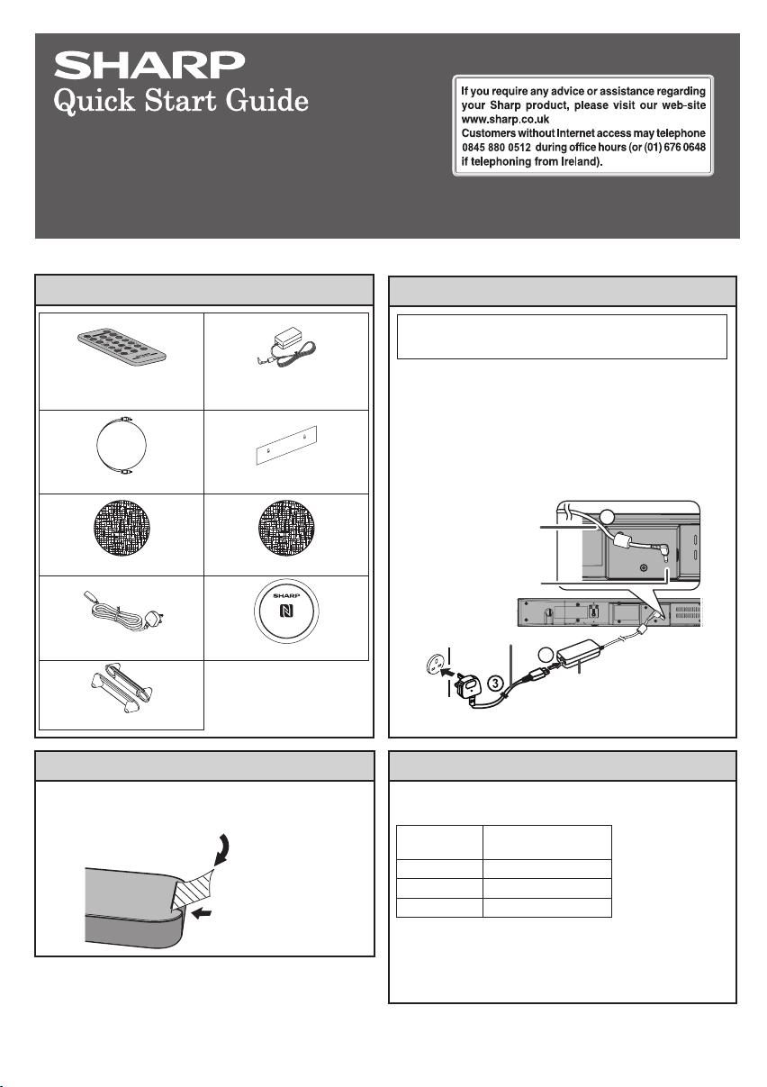
Accessories
Y
N/
B
-
O
ND
STA
WS
ODE
ND M
SICCI
MUTE
T
MU
SOU
INPU
A NE
ND
NEM
ROU
SUR
SS
TV
BYPA
CHVOL
VOL
A
S
W
322A
A
RRMCG
Remote control x 1 AC/DC adaptor x 1
Optical cable x 1 Pattern paper x 1
Velcro tape (hook type) x 1 Velcro tape (loop type) x 2
AC power lead x 1 NFC tag x 1
Spike leg x 2
Before using remote control
Before using the remote control, remove the
plastic shield from the battery holder.
Remote control
(RADPA100AWZZ)
HT-SB32D
Plastic shield
Battery holder
AC power connection
Make sure to unplug the AC power lead before
making any connections.
1 Plug the AC power lead into the AC/DC
adaptor.
2 Plug the AC/DC adaptor cable into the DC
INPUT socket on the sound bar.
3 Plug the AC power lead into a wall socket. The
PAIRING indicator turns BLUE.
Wall socket
AC/DC Adaptor
Cable
DC IN socket
(DC 19V)
AC power lead
1
2
AC/DC Adaptor
(AC 100 - 240 V ~ 50/60 Hz)
Turn on your system
Press the ON/STANDBY button.
The On/Standby/Input indicator lights up according to input
source:
Input source On/Standby/Input
OPTICAL IN Turns green
AUDIO IN Turns cyan
Bluetooth Turns blue
Note:
If the power does not turn on, check whether the power lead is
plugged in properly.
To set the sound bar to standby mode:
Press the ON/STANDBY button again. The PAIRING indicator
turns BLUE.
indicator
TINSEA474AWZZ
14G R AS
1
Page 2
509 mm
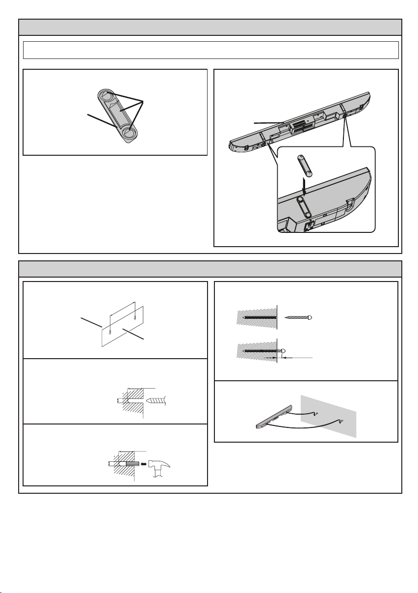
System preparation
Make sure to unplug the AC power lead before installing the sound bar or changing the position.
1 Peel the double sided tape separator. 2 Fix the spike leg onto the sound bar as shown.
Double sided
Spike leg
tape separator
Bottom of
sound bar
To mount the sound bar on the wall
1 Fix the pattern paper to the wall in horizontal
position as below.
Wall
surface
2 Make a hole on the wall following the screw point
marks on the pattern paper by using a drill.
3 Fix a wall mount plug into the hole using a ham-
mer, until it is ush with the wall surface.
548 mm
44 mm
8-9 mm
8-9 mm
Pattern paper
(supplied)
32 mm
Wall surface
32 mm
Wall surface
4 Fasten the screws to the wall as shown below.
(Total screw is 2 pieces)
Screw using
Wall surface
Wall surface
Screwdriver
4.5 mm - 5 mm
Gap from wall surface
5 Hang the sound bar onto the screws.
 Loading...