


DIGITALMASTER
L-758DR
L-758D
L-758
Operating Manual
Blank page

Safety Precautions
Before using your light meter, please read this “Safety Precautions” carefully and use it properly.
 WARNING
 CAUTION
NOTE:
Indicates hazard or unsafe use that can result in personal injury or death.
Indicates hazard or unsafe use that can result in personal injury or damage to your light meter.
Indicates a caution or limitation that accompanies operation. Please read the note to avoid incorrect operation.
Reference: Provides the reference information and related functions that are useful in operating. We recommend that you read these references.
 WARNING
•Please place light meter in a location where an infant cannot reach and accidentally get the strap wrapped around his or her neck. There is danger of strangulation.
•Keep the synchro terminal cap out of reach of young children, as swallowing such objects can cause suffocation.
•Never place batteries in fire, short, disassemble, heat or charge them. The batteries might break down, and cause damage, injury or pollute the environment.
 CAUTION
•There is a danger of electric shock and damage to product if your meter is handled with wet hands, in the rain, near water or where there is a lot of moisture, when you use cord flash mode. If you are using flash mode in these conditions, we recommend Cordless Flash mode or Radio Triggering mode. Always attach the synchro terminal cap on to the synchro connector when the light meter is exposed to wet or rainy conditions.
•Do not look directly at the sun through the viewfinder, because of potential eye injury.

Table of Contents
Safety Precautions |
|
Table of Contents |
|
1. Parts Designation ............................................................................................... |
1 |
1. Light Meter Parts .............................................................................................. |
1 |
2. Supplied Accessories ....................................................................................... |
2 |
2. Explanation of the Liquid Crystal Display(LCD) ............................................. |
3 |
3. Before Using ....................................................................................................... |
7 |
1. Attach the strap ................................................................................................ |
7 |
2. Inserting the battery .......................................................................................... |
7 |
3. Checking battery capacity ................................................................................ |
7 |
4. Replacing the battery during measurement or when using the memory function .. |
8 |
5. Auto Power Off function ................................................................................... |
8 |
6. Setting ISO 1 sensitivity ................................................................................... |
8 |
7. Setting ISO 2 sensitivity ................................................................................... |
8 |
8. Jog Wheel Lock or Lock Off ............................................................................. |
9 |
9. Setting the Measuring and Memory button configuration ................................. |
10 |
4. Basic Operation .................................................................................................. |
11 |
1. Incident or reflected spot measuring ................................................................ |
11 |
2. Setting measuring mode .................................................................................. |
12 |
3. Incident Measurement Mode ............................................................................ |
13 |
4. Reflected Measurement Mode (spot metering) ................................................ |
14 |
5. Measurement ...................................................................................................... |
15 |
1. Measuring ambient light ................................................................................... |
15 |
1-1 Shutter Speed Priority mode ...................................................................... |
15 |
1-2 Aperture Priority mode ................................................................................ |
17 |
1-3 EV mode ..................................................................................................... |
18 |
1-4 Cinematography ......................................................................................... |
19 |
2. Measuring electronic flash ................................................................................ |
21 |
2-1 Cord Flash mode ........................................................................................ |
21 |
2-2 Auto-reset cordless flash mode .................................................................. |
22 |

Table of Contents |
|
2-3 Cord multiple flash (cumulative) mode ....................................................... |
24 |
2-4 Cordless multiple flash (cumulative) mode ................................................. |
25 |
2-5 Flash analyzing function ............................................................................. |
27 |
2-6 Wireless Flash Radio Triggering ................................................................. |
28 |
6. Advanced Functions .......................................................................................... |
31 |
1. Memory function ............................................................................................... |
31 |
2. Averaging function ............................................................................................ |
32 |
3. Contrast Function ............................................................................................. |
32 |
4. How to use an incident illuminance (LUX or FC) meter (L-758DR/758D) ........ |
34 |
5. How to use a reflected luminance (cd/m2 or FL) meter (L-758DR/758D) ......... |
35 |
6. How to use the Exposure compensation function ............................................ |
36 |
7. How to use Calibration compensation function ................................................ |
37 |
8. Filter compensation .......................................................................................... |
38 |
8-1 Filter compensation (1) ............................................................................... |
38 |
8-2 Filter factor number compensation (2) (L-758CINE only) ........................... |
39 |
9. Custom setting function .................................................................................... |
40 |
7. Camera Exposure Profiling ............................................................................... |
42 |
1. Calibration testing for exposure profiling .......................................................... |
42 |
2. Input test target data ........................................................................................ |
44 |
2-1 Sekonic Application software ...................................................................... |
44 |
2-1-1 Outline of software ............................................................................. |
44 |
2-2 Manual Exposure Profile Input ................................................................... |
45 |
3. How to use Exposure Profiling mode ............................................................... |
48 |
3-1 Selecting Camera Exposure Profiling ......................................................... |
48 |
3-2 Analog scale ............................................................................................... |
48 |
3-2-1 Aperture scale .................................................................................... |
48 |
3-2-2 EV scale ............................................................................................. |
48 |
3-2-3 MID.TONE button .............................................................................. |
49 |
8. Optional Accessories ......................................................................................... |
52 |
9. Technical Data .................................................................................................... |
54 |

Table of Contents
10.Care and Maintenance ...................................................................................... |
56 |
FCC & IC compliance information ........................................................................ |
57 |

1. Parts Designation
1.Light Meter Parts
!8Spot Lens
Memory button*
Power button (ON/OFF switch)
@1USB Port
ISO 1 button
(“A” in radio channel setting)
Mid-Tone button
("C" in radio channel setting)
Mode button
Strap eyelet
@41/4” Tripod Socket
Lumisphere retracting ring
Lumisphere
Liquid Crystal Display (LCD)
Average / ∆ EV (Brightness Difference)
button
Jog Wheel
ISO 2 button (“B” in radio channel setting)
@3Memory Clear button
(“D” in radio channel setting)
Flash Synchro terminal
!9Incident/Reflected Spot
Selector Dial
@2Eyepiece (with Diopter
Adjustment)
Measuring button*
Battery Compartment Cover
Battery Cover Latch
 RT-32FCC/CE Radio
transmitter module
Battery Compartment |
@5Connector cover |
L-758DR
*Measuring button and memory button can be swithced in Custom settings.
L-758D/L-758CINE
-1-
1. Parts Designation
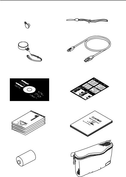
2.Supplied Accessories
@6Synchro Terminal Cap |
@7Strap |
(Attached to meter) |
|
@8Lens Cap |
@9USB Cable |
(Attached to meter) |
|
#0CD-ROM for Software
(Data Transfer Software, USB driver, Operating manual and Software guide)
#1Sticker for Multi-key Operation and CS (Custom Setting)


#2Quick Guide (in Japanese/English) |
#3Operating Manual |
#4Battery (CR-123A) |
#5Soft Case |
-2-

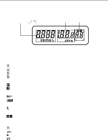
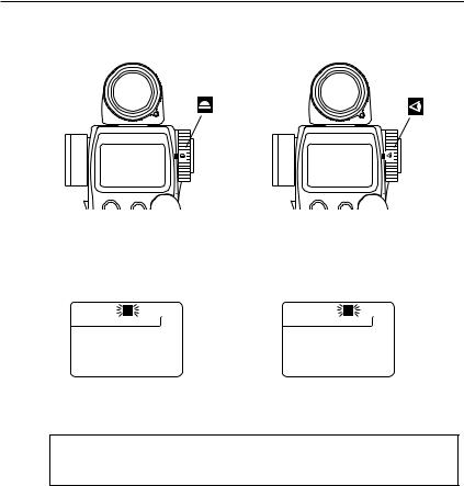
2. Explanation of the Liquid Crystal Display (LCD)
LCD for L-758DR/L-758D
LCD for L-758CINE
NOTE:
For explanation purposes, the display illustrated here shows all icons and readouts simultaneously. Actual LCD screen will not show all icon as above during normal use.
Auto Electro-Luminescent Display (EL)
•In low light (EV 6 or less), a green backlight will automatically illuminate the entire LCD.
•The LCD will not be automatically illuminated during measurements, in Cordless Flash or Wireless flash radio triggering mode.
•The Electro-luminescent backlight will automatically turn off 20 seconds after last operation.
-3-
2. Explanation of the Liquid Crystal Display
Display in viewfinder
In setting :
Flash analyzing :
Luminance : 
 /
/  (Only L-758CINE)
Measuring Mode Icons
Ambient (see page 15)
Auto-Reset Cordless Flash (see page 22)
Cord Flash (see page 21)
Wireless flash radio triggering mode (see page 28)
Incident / Reflected Spot Mode Icons (see page 11)
Appears when in Incident mode
Appears when in Reflected Spot mode
ISO Display (see page 8)
Displays ISO 1 setting
Displays second ISO setting when ISO 2 button is pressed
Flash Analyzing indicator (see page 27)
0 to 100% in 10% increments (percentage of the flash in the total exposure)
+/- Exposure/Calibration Compensation display (see page 36)
Exposure compensation--- appears on the upper side of the main LCD.
Calibration compensation--- appears only in the calibration setting mode.
Digital aperture value, Aperture Priority, EV Brightness Difference, Average function, EV display
Appears when Aperture Priority (f/stop) mode is selected (see page 17)
Appears when using Contrast function (see Page 32)
Appears when using Averaging function and Contrast function (see page 32) Appears when using EV mode (see page 18)
-4-
2. Explanation of the Liquid Crystal Display
Analog Scale
Displays measured values as icons along the apertures or Latitude EV scale. The scale is graduated in full or 1/3 stop increments for measurements. Memorized and averaged values are also display along the scale.
•Aperture scale (upper scale) displays in all mode except Aperture priority mode.
f 0.7 to f 90 in full stops appears in all modes except aperture priority mode (L-758)
f 0.5 to f 64 in full stops appears in all modes except aperture priority mode (L-758CINE)
•EV scale (lower scale) displays in all mode except Multiple flash cumulative mode.
+/-7 stops from Mid.Tone (0) appears in aperture priority mode, or other modes if selected.
•Value display scale
Appear to indicate last measured/ memorized/ averaged values and brightness difference value below the aperture scale or above the latitude scale depending on which scale has been selected.
Appears when measurement is below display range
Blinks when measurement is below measurement range
Appears when measurement is above display range
Blinks when measurement is above measurement range
Dynamic range/clipping point icons
Indicates dynamic range and clipping point of a selected camera exposure profiling.
Shutter priority indicator, shutter speed display for still photography or frames per second (f/s) for cinematography
Appears when Shutter Priority (T) is selected mode (see page 15)
Appears when shutter speed is in minutes
Appears when shutter speed is in full seconds
Appears when cine speed is set in frames per second (see page 19)
Battery Power Indicator (see page 7)
Memory / Multiple Flash Indicator Display
Appears when Multi (cumulative) flash measurement mode is selected and shows the cumulated number of flash measurements (see page 24)
Appears when reading is memorized and shows the number in memory (see page 31)
Radio triggering channel and Quad-triggering zone display (see page 28)
Triggering Channel Numbers

 Selective Quad-Triggering Zone
Camera profile selector display
USB icon
Appears when a USB cable is connected to the light meter and a computer.
-5-
2. Explanation of the Liquid Crystal Display
Shutter angle (L-758CINE)
Appears when shutter angle is set to a value other than 180 degrees (see page 19)
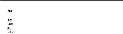
Illuminance mark / Luminance mark (L-758CINE)
Appears when Foot-Candle is selected
Appears when Lux is selected
Appears when Foot-Lambert is selected
Appears when cd/m2 is selected
-6-

3. Before Using
1.Attach the strap
Attach the Strap @7by passing the small loop end through the eyelet and passing the other end of strap through it.
MOO
 WARNING
•To avoid a danger of strangulation, please keep the strap in a location where an infant cannot reach it and accidentally get the strap wrapped around his or her neck.
2.Inserting the battery
1.Requires one 3.0 v CR123A lithium battery (included).
2.Open the Battery compartment cover latch , and remove the Battery compartment cover .
3.Insert the battery, observing the polarity with the +,- marks
in the battery compartment . 
4.Align the tabs of the Battery compartment cover with the
notches in the back of the meter, and press down to close  the Battery compartment cover latch.


NOTE:
•To prevent loss of All-weather seal, be careful that dirt does not get stuck on the rubber seal and that the seal is not damaged.
•Remove battery if meter is not used for an extended period. Batteries can leak and damage the light meter. Dispose of used batteries properly.
•If the LCD does not light, check that the battery capacity is sufficient, and check that the battery positive and negative terminals are not reversed.
•The L-758D/L-758CINE has a connector for a plug-in radio transmitter module. Do not remove the connector cover unless you are installing the radio module, failure to do so could cause the electronic circuit board to be exposed to damaging static electricity.
3.Checking battery capacity
•When the Power button is ON, the battery power indicator on the LCD is displayed.
(Displayed) |
Battery power level is good. |
(Displayed) |
Battery power level is low. Have a spare battery ready. |
(Blinking) |
Replace battery immediately. |
Reference:
•If the LCD screen turns off immediately after the display appears when power is first applied, that is an indication that the battery is dead. Please promptly replace the battery. We recommend you always have a spare battery on hand.
•A spare battery can be stored in a provided compartment of the L-758DR's case (see sticker "OPEN END TO BACK".
•Under our testing condition, the battery life is approximately 60 hours with continuous use under normal temperature.
•The battery supplied with this light meter, may not be able to meet battery life mentioned above because of undetermined shelf life or storage condition.
-7-

3.Before Using
4.Replacing the battery during measurement or when using the memory function
1.Always turn the power OFF before replacing the battery. If the battery is removed with the power ON, measurements and settings in memory can no longer be recalled.
2.If after replacing the battery, or during measurements, strange screens (displays that have not been set) appear on the LCD, or nothing happens, no matter what button is pushed, remove the battery and wait at least ten seconds and then replace the battery. This allows the software to automatically reset.
 WARNING:
•Never place batteries in fire, short, disassemble, or heat them. The batteries might break down, and cause an accident, injury or pollute the environment.
NOTE:
•A three second pause between power on and off is recommended to avoid damage to the meter.
5.Auto Power Off function
1.To conserve battery power, the meter will turn off about twenty minutes after last use.
2.Whether the Auto Power Saving feature turns the power off or the Power button is pressed, the settings and measured values remain stored in memory. When the Power button is pressed again the last settings are displayed.
Reference:
•The power shuts off automatically after 1 minute when the power button is pressed and held.
•Auto power off time is adjustable in Custom settings. (See page 40 for details)
6.Setting ISO 1 sensitivity
1.Hold down the ISO1 button and turn the Jog wheelto select the desired ISO sensitivity.
2.You can also change the ISO sensitivity after taking measurements. The new value is automatically displayed.
7.Setting ISO 2 sensitivity
1.This feature is useful when using a different ISO sensitivity (film or digital), Polaroid proofing film, or for exposure correction (when using a filter, extension tubes, bellows factor or another camera etc.).
2.Hold down the ISO 2 button and turn the Jog wheel to select the desired ISO sensitivity.
3.Once this is set, after taking a measurement, the measured value for the second ISO sensitivity will be displayed when the ISO 2 button is pressed.
4.You can also change the second ISO sensitivity after taking measurements. The new value is automatically displayed.
Reference:
•The following settings are possible when using custom setting function P40.
1.It is possible to set ISO 2 for Filter compensation. These values can be set within a range of
± 5 EV in 1/10 steps and are display in the ISO 2 area.
2.Filter factor number compensation enables you to set seven types of filters frequently used in the CINE industry. (Kodak Wratten Filters)(L-758CINE only)
-8-

3. Before Using
8. Jog Wheel Lock or Lock Off
1. Hold down the Mode button and ISO1 button and “LOC” will appear to indicate that the Jog Wheel is locked. The last measurement is held until the lock is released, even if the Jog wheel is accidentally moved.
However, if the measurement button is pressed, a new measurement is displayed with the same locked settings.
2. To release the Jog Wheel lock, perform the same operation for the Jog Wheel lock, Hold down the Mode set button and ISO1 button and “Off” will appear to indicate that the Jog Wheel lock is released.
Reference:
•If power of the meter is turned off or auto off is activated when in the Jog Wheel locked position, the lock function will continue operating when the meter is turned on again.
-9-
3.Before Using
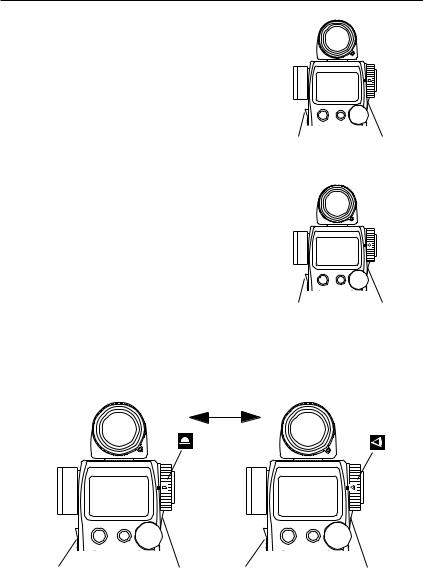
9.Setting the Measuring and Memory button configuration
In the custom settings mode (refer to P40), the Measuring button and the Memory button can be set as follows.
1.For Incident measuring
The Measuring button and Memory button is set in the standard configuration. (Described on Page 1 in Light
Meter Parts) Please make sure that the default value in the Custom settings mode is set to .(Custom No.17, Item No. 0)
Memory |
Measuring |
button |
button |
Configuration 1) |
|
2.For Reflected (Spot) measuring
If the standard buttons configuration is inconvenient for spot metering, the Measuring button and Memory button can be switched. Set the Custom settings mode to Custom No. 17, Item No. 1
Measuring |
Memory |
button |
button |
Configuration 2) |
|
3.For both Incident/Reflected (Spot) measuring simultaneously
You can set the buttons configuration automatically according to light measuring method. In incident mode, the buttons configuration is 1), but in reflected mode, the buttons configuration is 2). For this setting, please set (Custom settings mode No. 17 and Item No 2).
Incident |
Automatically |
Reflected |
|
|
|
|
switched |
|
Memory |
Measuring |
Measuring |
Memory |
button |
button |
button |
button |
|
Configuration 3) |
|
|
-10-
4. Basic Operation
1.Incident or reflected spot measuring
1.To set for either incident or reflected light operation, turn the Incident / Reflected Spot Selector Dial on the eye piece, to the desired position ( or
or  mark) until it clicks.
Incident operation |
Reflected Spot operation |
2.When incident operation is selected, the mark will blink for ten seconds and when Reflected Spot operation is selected the
  mark will blink for ten seconds on the LCD.
Incident operation |
Reflected Spot operation |
NOTE:
•Before taking measurements, always make sure that the desired measurement mode ( or
or  ) is chosen by checking the LCD or that the Incident/Reflected Spot Selector Dial is clicked in proper position.
•Do not rotate the Spot lens ring. There is danger of damage.
-11-
4. Basic Operation
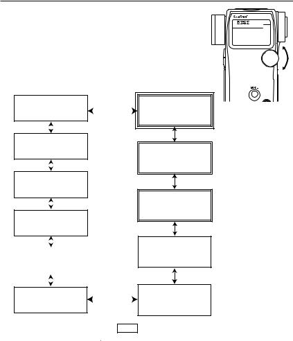
2.Setting measuring mode
1.Hold down the Mode button and turn the Jog wheel to select the desired mode. The mode switching sequence is shown in the chart below:
Shutter Speed Priority mode |
|
|||
(Available light) |
|
|||
See page 15 |
|
|||
|
|
|
|
|
|
|
|
|
|
Aperture Priority mode |
|
|||
(Available light) |
|
|||
See page 17 |
|
|||
|
|
|
|
|
|
|
|
|
|
EV mode (Available light) |
|
|||
See page 18 |
|
|||
|
|
|
|
|
|
|
|
|
|
LUX, FC |
→ CINE only |
|||
FL, cd/m2 |
||||
See page 34,35 |
|
|||
|
|
|
|
|
|
|
|
|
|
|
|
|
|
|
Auto Reset Cordless Flash |
|
|
|
|
mode |
|
|
|
|
See page 22 |
|
|
|
|
|
|
|
|
|
|
|
|
||
|
|
|
|
|
Cordless Multiple Flash |
|
|||
(Cumulative) mode |
|
|
||
|
|
|||
See page 25 |
|
|||
2. Modes enclosed in dotted lines (See page 40)
Wireless Multiple Flash |
|
|
Radio Triggering mode |
|
|
See page 28 |
with Radio |
|
|
transmitter module |
|
Wireless Flash Radio |
with Radio |
|
transmitter module |
||
Triggering mode |
||
|
||
See page 28 |
|
|
Wireless Flash channel |
with Radio |
|
transmitter module |
||
Setting mode |
||
|
||
See page 28 |
|
|
Cord Multiple Flash |
|
|
(Cumulative) mode |
|
|
See page 24 |
|
|
Cord Flash mode |
|
|
See page 21 |
|
can only be selected with custom setting.
3. Modes enclosed in |
|
lines can only be selected with L-758DR. For L-758D and L-758CINE, |
they can be selected |
when |
Optional Radio Transmitter Module is installed. (See page 28) |
4.In addition to exposure reading, L-758CINE displays FC or LUX in incident light mode, and FL or cd/m2 in reflected light mode.(See page 34)
Reference:
•Available light is continuous light like natural light (sunlight) or tungsten lamps and florescent lamps like pulsing light sources.
•Flash light is a brief, intense burst of light made by such as electronic flash units or flash bulbs.
-12-
4. Basic Operation
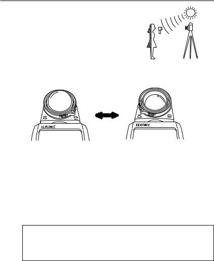
3.Incident Measurement Mode
Incident light measuring is the measurement method that employs either the Lumisphere or Lumidisc functions. Measurements should be with the Lumisphere aimed towards the camera direction from the subject position.
1.You can select extended or retracted lumisphere measuring positions by rotating the Lumisphere retracting ring (clockwise or counter-clockwise) until it clicks into position.
Extended Lumisphere |
Retracted Lumisphere |
|
(Lumidisc) |
2.When the Lumisphere is extended. (3-D Light Measurement)
This is used to measure people, buildings, and other three dimensional objects. Measurements are basically made by the method of measuring with the lumisphere aimed in the camera direction (more precisely, in the direction of the lens axis) at the position of the subject.
3.When the Lumisphere is retracted (flat diffuser function)
This is used to measure manuscripts, paintings or other flat copy. It can also be used for Contrast function (see page 32) or measuring illumination (see page 34).
NOTE:
•If the light meter is used with the Lumisphere retracting ring in a middle position, distributed light quality will change, and suitable measurements cannot be made.
•Do not push the Lumisphere down with your finger or hand. Always use the Lumisphere retracting ring.
•If the lumisphere becomes soiled, wipe it with a soft, dry cloth. Organic solutions (paint thinner, benzene, etc.) must not be used under any circumstances.
-13-
4. Basic Operation
4.Reflected Measurement Mode (spot metering)
This method measures the brightness (luminance) of the light reflected from the subject. It is useful for distant objects such as landscapes, when you cannot go to the position of the subject, or for metering subjects that generate light (neon signs, etc.), highly reflective surfaces or translucent subjects (stained glass, etc.).
1.Take the measurement by aligning the circle inside the viewfinder with the subject area to be measured.
2.The black circle A in the finder indicates the measurement range. The light receiving angle is 1 degree .
A
(Display in spot viewfinder)
< Diopter Adjustment >
Turn the eyepiece @2and adjust the diopter so that the circle in the finder is clearly visible when you look into the finder.
< Step-Up Ring (Lens Hood)> (optional)
The step-up ring (30.5mm → 40.5mm), available as an optional accessory, makes it possible to mount step-up rings and filters. This simplifies the setting of exposure without the troublesome correction calculation of polarizing filters, etc. (see page 52)
The step-up ring can also be used as a lens hood to prevent lens flare and erroneous light measurements from glare, it also protects the spot lens from scratching, soiling, etc.
-14-
5. Measurement
1.Measuring ambient light
In this measurement mode, we have the choice of shutter priority mode, aperture priority mode or
EV mode. Hold down the Mode button and turn the Jog wheel to select ambient measurement mode .
.
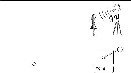
1-1 Shutter Speed Priority mode
1.Hold down the Mode button and turn the Jog wheel to select Shutter Speed Priority mode  .
.
2.Turn the Jog wheel to set the desired shutter speed.
3.Press the Measuring button to take a measurement. Release the Measuring button to complete the measurement. The measured value (aperture value) at that time will be displayed.
While pressing the Measuring button, the meter measures continuously until it is released.
Reference:
Set
shutter speed Measured f stop value
1/10 f stop
Measured f stop(blinking)
•It is possible to switch between full, 1/2 and 1/3 shutter speeds with custom setting (see page 36).
•You can set shutter speeds from 30 minutes to 1/8000 seconds. After 1/8000 the shutter speeds of 1/200 and 1/400 can be set.
•After taking a measurement, the F stop value corresponding to the shutter speed is displayed. The measured F stop value automatically corresponds to the shutter speed if the shutter speed is changed by rotating Jog wheel.
•The L-758DR/758D displays the measured aperture value in either full or 1/3 stop increments on the analog scale from f/0.7 to 90, while L-758 CINE displays it in either full or 1/3 stop increments on the analog scale from F0.5 to F64.
•You can select aperture scale or EV scale by holding MODE button and pressing AVE. / EV.
-15-
 Loading...