


Super Zoom Master
L-608/L-608 


Operating Manual

Blank page

Congratulations on your purchase of a Sekonic Super Zoom Master L-608/L-608CINE Exposure Meter.
The Super Zoom Master L-608/L-608CINE is the latest addition to the extensive line of Sekonic Exposure Meters which have been market leaders.
It was designed to be the ultimate meter, a do-all instrument for the most demanding pros.
It is the first zoom spot meter with digital spot viewfinder readout on the market. Nine camera-quality lens elements are required to accomplish its 1° to 4° zoom range.
its sealed housing and controls make it water and moisture resistant. Yes, you can use it in the rain, but it is not an underwater meter.
The large LCD display makes reading easy, and it lights up automatically in dark surroundings.
In order not to crowd the controls, four functions which are less frequently used, are confined to DIP switches, located in the battery compartment.
Because of its many features, the L-608/L-608CINE requires this rather extensive manual. But since you will never use all of the function at the same time, once you have learned all about it, it is simple and its use will become second nature.
The Super Zoom Master L-608/L-608CINE has undergone extensive quality controls at every step of manufacture. Please read this instruction manual thoroughly, to be able to take advantage of its many features and to obtain the long service life it is designed for.
Thank you for your confidence in Sekonic.

Table of Contents
1. |
Parts Designation ................................................................................................................ |
1 |
|
2. |
Explanation of the Liquid Crystal Display (LCD) .................................................................. |
2-3 |
|
3. |
Before Using ........................................................................................................................ |
4-6 |
|
|
1. |
Attach the strap ......................................................................................................... |
4 |
|
2. |
Inserting the battery .................................................................................................. |
4 |
|
3. |
Checking battery capacity ......................................................................................... |
4 |
4.Replacing battery during measurement
|
|
or when using the memory function .......................................................................... |
5 |
|
|
5. |
Auto Power Off function ............................................................................................. |
5 |
|
|
6. |
Setting main ISO film speed ...................................................................................... |
5 |
|
|
7. |
Setting second ISO film speed (ISO 2) ..................................................................... |
5 |
|
|
8. |
Mesurement Lock and Measurement Lock Off .......................................................... |
6 |
|
4. |
Basic Operation ................................................................................................................... |
7-12 |
||
|
1. |
Incident or reflected spot measuring ......................................................................... |
7 |
|
|
2. |
Setting measuring mode ........................................................................................... |
8 |
|
|
3. |
Setting DIP switches .................................................................................................. |
9 |
|
|
4. |
When set for incident light ......................................................................................... |
10 |
|
|
5. |
When set for reflected light (spot metering) .............................................................. |
11 |
|
5. |
Measurment |
........................................................................................................................ |
13-22 |
|
|
1. |
Measuring Ambient Light ........................................................................................... |
13 |
|
|
|
1-1 Shutter Speed Priority mode ........................................................................... |
13 |
|
|
|
1-2 |
Aperture Priority mode .................................................................................... |
14 |
|
|
1-3 |
EV mode ......................................................................................................... |
15 |
|
|
1-4 |
Cinematography .............................................................................................. |
16 |
|
2. |
Measuring Flash Light ............................................................................................... |
18 |
|
|
|
2-1 |
Cord Flash mode ............................................................................................. |
18 |
|
|
2-2 Auto Reset Cordless Flash mode ................................................................... |
19 |
|
|
|
2-3 Cord Multiple Flash (cumulative) mode ........................................................... |
21 |
|
|
|
2-4 Cordless Maltiple Flash (cumulative) mode .................................................... |
22 |
|
6. |
Advanced Functions ............................................................................................................ |
24-35 |
||
|
1. |
Memory function ........................................................................................................ |
24 |
|
|
2. |
Averaging function ..................................................................................................... |
25 |
|
|
3. |
Brightness Difference function ................................................................................... |
25 |
|
|
4. |
How to use an incident Illuminance (LUX or FC) Meter ............................................ |
27 |
|
|
5. |
How to use a reflected luminance (cd/m2 or FL) meter ............................................. |
28 |
|
|
6. |
How to use Exposure compensation function ........................................................... |
29 |
|
|
7. |
How to use Calibration compensation function ......................................................... |
30 |
|
|
8. |
Filter compensation ................................................................................................... |
31 |
|
|
9. |
Flash analyzing function ............................................................................................ |
32 |
|
|
10. |
Custom setting function ............................................................................................. |
33 |
|
|
11. |
Wireless flash radio triggering system ....................................................................... |
35 |
|
7. |
Accessories |
........................................................................................................................ |
38-39 |
|
8. |
Technical Data ..................................................................................................................... |
40-41 |
||
9. |
Safety Guide ........................................................................................................................ |
42 |
||
10. |
Care and Maintenance ........................................................................................................ |
43 |
||
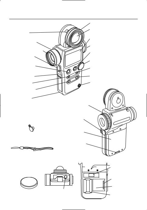
1. Parts Designation
!4Lock lever
@6Zoom Lens Ring
@7Zoom Lens Protective Glass
u Memory button
!2Power button (ON/OFF switch)
!3Mini Light Receptor
Outlet
!1ISO 1 button
!0Mode set button
o Strap eyelet
@0Synchro Terminal Cap
@1Strap
@3Zoom Lens Cap
|
SEKONIC |
|
|
|
|
∆ |
V |
|
|
E |
|
|
|
E/ |
|
M |
|
AV |
|
EM |
ER |
|
|
W |
|
|
|
ORY |
PO |
|
|
|
|
O2 |
|
|
|
|
IS |
|
O1 |
|
AR |
|
IS |
|
|
|
|
|
LE |
|
|
M.C |
|
|
DE |
|
|
|
MO |
|
|
|
|
r |
|
|
|
ste |
|
|
m |
Ma |
|
|
oo |
|
|
|
r Z |
|
|
|
pe |
|
|
|
Su |
|
|
|
-608 |
|
|
|
L |
|
|
q Lumisphere retracting ring
w Lumisphere
e Liquid Crystal Display (LCD)
@4Eyepiece (with Diopter Adjustment)
rAverage / ∆ EV (Brightness Difference) button
t Jog Wheel
y ISO 2 button
@5Memory Clear button
i Flash Synchro terminal
@8Incident/Reflected Spot
Selector Switch
!5Measuring button
!6Battery Compartment Cover
!7Battery Cover Latch
!8DIP Switches
@2Connector cover
RT-32 Radio transmitter
module compartment
@91/4” Tripod Socket
!9Battery Compartment
-1-

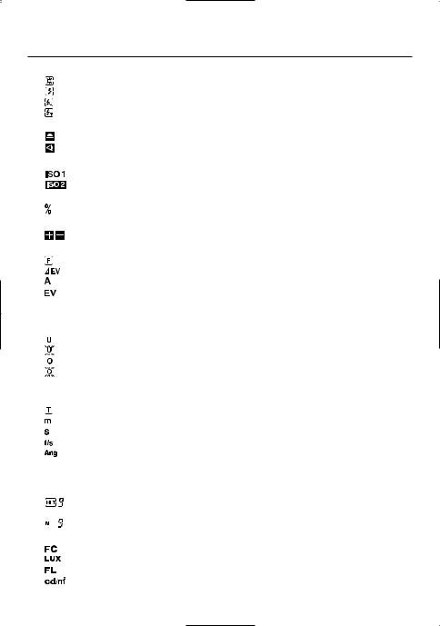
2. Explanation of the Liquid Crystal Display |
|||
L-608 |
!0q |
w |
e |
o |
|
|
r |
|
|
|
!1 |
i |
|
|
t |
|
|
|
|
|
u |
|
i |
L-608CINE |
!0q |
w |
e |
|
|||
o |
|
|
r |
|
|
|
!1 |
i |
|
|
t |
|
|
|
|
NOTE: u i
For explanation purposes, the display illustrated here shows all icons and readouts simultaneously. Actual display will never show as above.
Auto Electro-Luminescent Display (EL)
•In low light (EV 3 or less), a green backlight will automatically illuminate the entire LCD. When using the Mini Light Receptor or a Booster (optional accessories) the LCD will be illuminated after measuring, regardless of the ambient light level.
•The LCD will not be automatically illuminated during measuring, in Cordless Flash mode or Wireless flash radio triggering mode.
•The Electro-luminescent backlight will automatically turn off 20 seconds after last operation.
-2-
2. Explanation of the Liquid Crystal Display
qMeasuring Mode Icons
Ambient (see page 13)
Auto-Reset Cordless Flash (see page 19)
Cord Flash (see page 18)
Wireless flash radio triggering mode (see page 35)
wIncident / Reflected Spot Function Icons (see page 7)
Appears when in Incident mode
Appears when in Reflected Spot mode
eISO Display
Displays ISO film setting
Displays second ISO film setting when ISO 2 button is pressed
rFlash Analyzing indicator
0 to 100% in 10% increments (percentage of the flash in the total exposure)
t+/- Compensation Indicator
Appears when +/- Compensation is set
yDigital aperture value, Aperture Priority, EV Brightness Difference, Average function, EV display
Appears when in Aperture Priority (f/stop) mode (see page 14)
Appears when using brightness difference function (See Page 25)
Appears when using Averaging function (see page 25)
Appears when using EV mode (see page 15)
uAnalog Scale
Displays marks at apertures or shutter speed indicating full or half stop values (608),or full or 1/3 stop values (608 CINE) for measurement, also displays memory and average values
Appears when below display range
Blinks when under exposed below measurement range
Appears when above display range
Blinks when over exposed above measurement range
iShutter priority indicator, shutter speed display for still photography or frames per second (f/s) for cinematography
Appears when Shutter Priority (T) mode (see page 13) Appears when shutter speed is in minutes
Appears when shutter speed is in full seconds
Appears when cine speed is set in frames per second (see page 16)
Appears when shutter angle is set to a value other than 180 degrees (608 CINE)(see page 17)
oBattery Power Indicator (see page 4)
!0Memory / Multiple Flash Indicator Display
Appears when Multi (cumulative) flash measurement mode and shows the cumulated number of measurements (see page 21)
Appears when reading is memorized and shows the number in memory (see page 24)
!1Illumination mark/brightness mark
Appears when Foot-Candle is selected (608/608 CINE)
Appears when Lux is selected (608/608 CINE)
Appears when Foot-Lambert is selected (608 CINE) Appears when Cd/m2 is selected (608 CINE)
-3-
3. Before Using
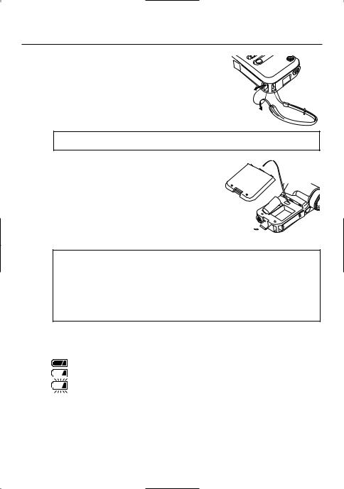
1.Attach the strap
Attach the Strap @1by passing the small end loop through the eyelet o and passing the other end of strap through it.
MOODE
|
Zoom |
Master |
|
Super |
|
||
0 |
|
||
-6 |
8 |
||
L |
|
|
|
 WARNING
•Please place in a location where an infant cannot reach and accidentally get the strap wrapped around his or her neck. There is danger of strangulation.
2.Inserting the battery
1.Requires one 3.0 v CR123A lithium battery.
2.Open the Battery compartment cover latch !7, and remove the Battery compartment cover !6.
3.Insert the battery, observing the polarity with the +,- marks
in the battery chamber. 
4.Align the tabs of the Battery compartment cover with the notches in the back of the meter, and press down to close
the Battery cover latch. 

NOTE:
•To prevent loss of All-weather seal, be careful that dirt does not get stuck on the rubber seal and that the seal is not damaged.
•Remove battery if meter is not used for an extended period. Batteries can leak and damage the exposure meter. Dispose of used batteries properly.
•If the LCD does not light, check that the battery capacity is sufficient, and check that the battery positive and negative terminals are not reversed.
•The meter has a connector for a plug-in radio transmitter module. Do not remove the connector cover unless you are installing the radio module, failure to do so could cause the electronic circuit board to be exposed to damaging static electricity.
3.Checking battery capacity
•When the Power button !2is ON, the battery power indicator on the LCD is displayed.
(Displayed) |
Battery power level is good. |
(Displayed) |
Battery power level is low. Have a spare battery ready. |
(Blinking) |
Replace battery immediately. |
Reference:
•We recommend you always have a spare battery on hand.
•If the liquid crystal display extinguishes immediately after the display appears when power is first applied, that is an indication that the battery is dead. Please promptly replace the battery.
•A3 second pause between power on and off is recommended to avoid damage to the meter.
-4-
3. Before Using
4.Replacing battery during measurement or when using the memory function
1.Always turn the power OFF before replacing batteries. If batteries are removed with the power ON, measurements and settings in memory can no longer be recalled.
2.If after replacing the battery, or during measurements, strange screens (displays that have not been set) appear in the LCD, or nothing happens, no matter what button is pushed, remove the battery and wait at least ten seconds and then replace the battery. This allows the software to automatically reset.
 WARNING:
•Never place batteries in fire, short, disassemble, or heat them. The batteries might break down, and cause an accident, injury or pollute the environment.
5.Auto Power Off function
1.To conserve battery power, the meter will turn off about twenty minutes after last use.
2.Whether the Auto Power Saving feature turns the power off or the Power button !2is pressed, the settings and measured values remain stored in memory. When the Power button is pressed again the last settings are displayed.
Reference:
•The power shuts off automatically after 1 minute when the power button is pressed and held.
6.Setting main ISO film speed
1.Hold down the ISO1 button !1and turn the Jog wheel
t to select ISO film speed for the film being used.
2.You can also change the ISO film speed after taking measurements. The new value is automatically displayed.
ISO 1
7.Setting second ISO film speed (ISO 2)
1.This feature is useful when using a second film with
different ISO film speed, using PolaroidTM proofing film, or for exposure correction (when using a filter, closeup photography, etc.).
2.Hold down the ISO 2 button y and turn the Jog wheel
to select ISO film speed of the film being used.
3.Once this is set, after taking a measurement, the measured value for the second film speed will be displayed
ISO 2
when the ISO 2 button is pressed.
4.You can also change the second ISO film speed after taking measurements. The new value is automatically displayed.
Reference:
•The following settings are possible when using custom setting function P33.
1.It is possible to set the Filter compensation within a range of ± 5 EV in 1/10 steps.
2.Filter factor number compensation enables you to set seven types of filters frequently used in the CINE industry. (Kodak Wratten Filters)(608 CINE only)
-5-
3. Before Using
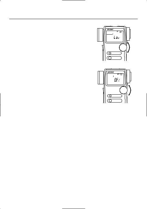
8.Mode and Setting Lock or Lock Off
1.Hold down the Mode set button !0and ISO1 button !1 and "LOC" will appear to indicate that the Settings are locked. The last measurement is held until the lock is released, even if the Jog wheel t is accidentally moved.
However, if the measurement button !5is pressed, a new measurement is displayed with the same locked settings.
2.To release the Measurement lock, perform the same operation for the Measurement lock, Hold down the Mode set button and ISO1 button and "Off" will appear to indicate that the Measurement lock is released.
ISO 1
MODE
ISO 1
MODE
Reference:
•If power to the meter is turned off or auto off is activated when in the locked position, the dial lock function will continue operating when the meter is turned on again.
-6-
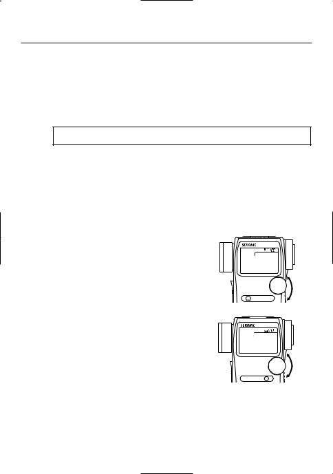
4. Basic Operation
1.Incident or reflected spot measuring
1.To set for either incident or reflected light operation, turn the Incident / Reflected Spot Selector Switch @8on the eye piece, to the desired position ( or
or  mark) until it clicks.
Incident operation |
Reflected Spot operation |
2.When incident operation is selected, the  mark will blink for three seconds and when Reflected Spot operation is selected the
  mark will blink for three seconds on the LCD.
|
|
|
|
|
|
Incident operation |
Reflected Spot operation |
||||
NOTE:
•Before taking measurements, always make sure that the desired measurement mode (  or
or  ) is chosen by checking the LCD or that the Incident/Reflected Spot Selector Switch is clicked in proper position.
-7-
4. Basic Operation
2.Setting measuring mode
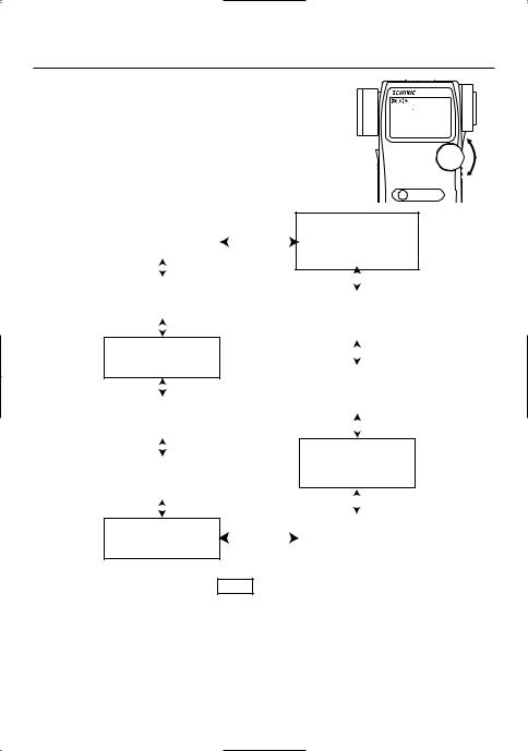
1. Hold down the Mode set button !0and turn the Set/change dial t to select the desired mode. The mode switching sequence is shown in the chart below:
MODE
|
|
Shutter Speed Priority mode |
|
|
|
Wireless Multiple Flash |
with Radio |
|||||
|
|
|
|
|
transmitter module |
|||||||
|
|
(Ambient light) |
|
|
|
|
|
|||||
|
|
|
|
|
|
|
Radio Triggering mode |
|||||
|
|
|
|
|
|
|
|
|||||
|
|
See page 13 |
|
|
|
|
|
|
||||
|
|
|
|
|
|
|
See page 37 |
Dip switch 2 |
||||
|
|
|
|
|
|
|
|
|
|
|
|
|
|
|
|
|
|
|
|
|
|
|
|
|
|
|
|
Aperture Priority mode |
|
|
|
|
|
|
||||
|
|
|
|
|
|
|
||||||
|
|
(Ambient light) |
|
|
|
|
|
Wireless Flash Radio |
with Radio |
|||
|
|
See page 14 |
|
|
|
|
|
|||||
|
|
|
|
|
|
|
transmitter module |
|||||
|
|
|
|
|
|
|
Triggering mode |
|||||
|
|
|
|
|
|
|
|
|
|
See page 37 |
|
|
|
|
|
|
|
|
|
|
|
|
|
||
|
|
EV mode (Ambient light) |
|
|
|
|
||||||
|
|
|
|
|
|
|
|
|||||
|
|
|
|
|
|
|
|
|||||
|
|
|
|
|
|
|
||||||
|
|
See page 15 |
|
|
|
Dip switch 1 |
|
|
with Radio |
|||
|
|
|
|
|
|
|||||||
|
|
|
|
|
|
|
|
Wireless Flash Sub/channel |
||||
|
|
|
|
|
|
|
|
|
|
|||
|
|
|
|
|
|
|
|
|
|
transmitter module |
||
|
|
|
|
|
|
|
|
|
|
Setting mode |
||
|
|
|
|
|
|
|
|
|
|
See page 35 |
|
|
|
|
LUX, FC |
|
|
|
|
|
|
||||
|
|
|
|
|
|
|
|
|
|
|||
|
|
FL, Cd/m2 |
→ |
CINE only |
|
|
|
|
|
|
||
|
|
|
|
|
|
|
||||||
|
|
See page 27,28 |
|
|
|
|
|
|
||||
|
|
|
|
|
|
|
|
|
|
Cord Multiple Flash |
|
|
|
|
|
|
|
|
|
|
|
|
|
||
|
|
|
|
|
|
|
|
|
|
|
||
|
|
|
|
|
|
|
|
|
|
|
||
|
|
|
|
|
|
|
|
|
|
(Cumulative) mode |
|
|
|
|
Auto Reset Cordless Flash |
|
|
|
|
||||||
|
|
|
|
|
See page 21 |
|
||||||
|
|
mode |
|
|
|
|
|
Dip switch 2 |
||||
|
|
See page 19 |
|
|
|
|
|
|
|
|
||
|
|
|
|
|
|
|
|
|
|
|||
|
|
|
|
|
|
|
|
|
|
|
|
|
|
|
Cordless Multiple Flash |
|
|
|
Cord Flash mode |
|
|||||
|
|
(Cumulative) mode |
|
|
|
See page 18 |
|
|||||
|
|
|
|
|
||||||||
|
|
See page 22 |
|
|
|
Dip switch 2 |
|
|||||
|
|
|
|
|
|
|
|
|||||
|
|
|
|
|
|
|
|
|
||||
• Modes enclosed in dotted lines |
|
can only be selected when the respective DIP switch |
||||||||||
is in ON position (see page 8). |
|
|
|
|
|
|
||||||
|
|
|
|
|
|
|
|
|
|
|
|
|
• Modes enclosed in |
|
lines can only be selected when Optional Radio Transmitter Mod- |
||||||||||
ule is installed. |
|
|
|
|
|
|
|
|
||||
|
|
|
|
|
|
|
|
|||||
•Each mode can be selected to display or not with custom setting.(See page 33)
•FC or LUX (Illuminance) can be displayed in incident light mode.
•FL or Cd/m2 (Luminance) can be displayed in reflected light mode. (608 CINE only)
Reference:
•Ambient light is continuous light like natural light (sunlight), fluorescent lamps or tungsten lamps.
•Flash light is a brief, intense burst of light made by such as electronic flash units or flash bulbs.
-8-
4. Basic Operation
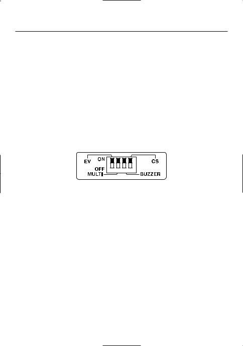
3.Setting DIP Switches
1.Switches for setting modes that are used infrequently are housed in the Battery compartment of the meter. Select the mode you want prior to beginning measurements.
2.The DIP switches can be set by sliding the DIP switch !8for the mode you want to select in the ON position.
*EV settings
When DIP switch 1 is turned on, EV exposure readings are possible. (ambient light)
*Multi settings
When DIP switch 2 is turned on, multiple flash cumulative mode is possible.
*Buzzer setting
When DIP switch 3 is on, the buzzer sounds when light from a flash is received in the cordless mode.
*CS setting (custom settings)
When DIP switch 4 is on, the mode changes to the custom setting mode, thereby enabling various settings (refer to P33).
1 2 3 4
-9-
4. Basic Operation
4.When set for incident light
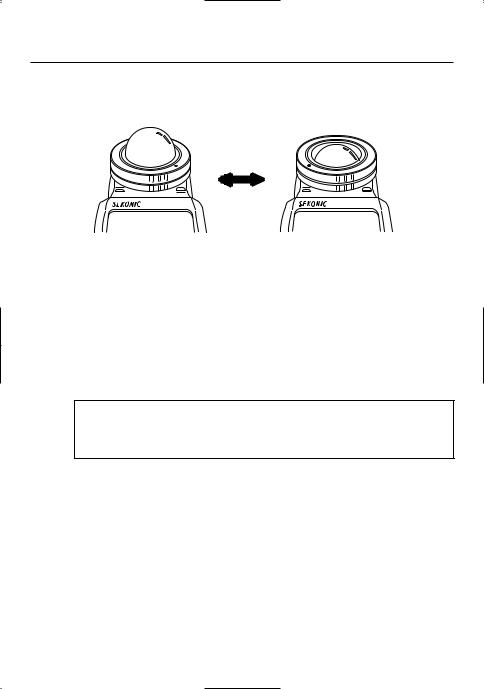
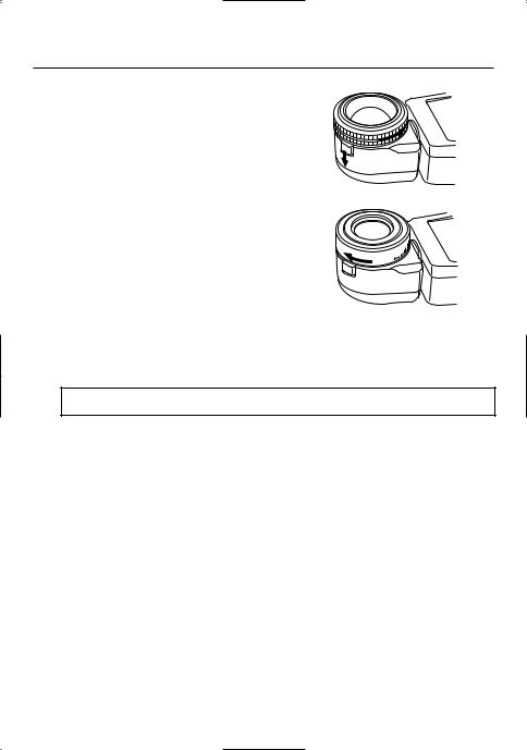
1.You can select extended or retracted lumisphere measuring positions by firmly rotating the lumisphere retracting ring (UP/DOWN) until it clicks into position.
Extended Lumisphere |
Retracted Lumisphere |
|
(Lumidisc) |
2.When the Lumisphere is extended. (3-D Light Measurement)
This is used to photograph people, buildings, and other three dimensional objects. Measurements are basically made by the method of measuring with the lumisphere aimed in the camera direction (more precisely, in the direction of the lens axis) at the position of the subject.
3.When the Lumisphere is retracted (flat diffuser function)
This is used to photograph manuscripts, paintings or other flat copy. It can also be used for measuring illumination levels (see page 27), or brightness difference (see page 25).
NOTE:
•If the device is used with the Lumisphere retracting ring in a middle position, distributed light quality will change, and suitable measurements cannot be made.
•Do not push the Lumisphere down manually. Always use the Lumisphere retracting ring.
•If the lumisphere becomes soiled, wipe it with a soft, dry cloth. Organic solutions (paint thinner, benzene, etc.) must not be used under any circumstances.
-10-
4. Basic Operation
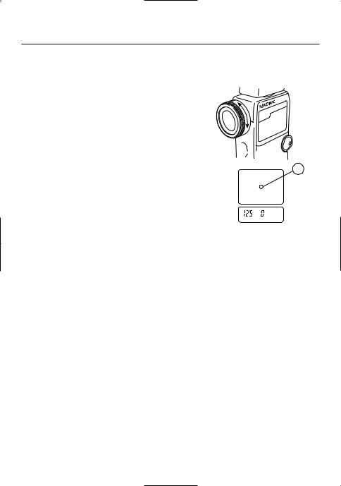
5.When set for reflected light (spot metering)
1.This method measures the brightness (luminance) of the light reflected from the subject. It is useful for distant objects such as landscapes, when you cannot go to the position of the subject, or for metering subjects that generate light (neon signs, etc.), highly reflective surfaces or translucent subjects (stained glass, etc.).
2.The spot metering area can be selected by turning the Zoom Lens ring @6while looking through the viewfinder from the camera position.
3.Take the measurement by aligning the circle inside the viewfinder with the subject area to be measured.
|
O |
M SP |
|
O |
OT |
||
|
|
1 |
|
Z |
|
|
~ |
|
|
|
° |
|
|
|
4 |
|
|
|
|
|
|
||
|
|
|
|
|
|
|
|
|
|
I |
|
|
|
|
|
|
|
C |
S |
|
|
N |
|
|
|
OKE |
|
ryomeM
A
4.The black circle A in the finder indicates the measurement range. The light receiving angle is 1 degree with the telephoto setting of the zoom lens and 4 degrees with the wide angle.
(Display in spot viewfinder)
< Diopter Adjustment >
Turn the eyepiece @4and adjust the diopter so that the circle in the finder is clearly visible when you look into the finder.
< Step-Up Ring (Lens Hood)> (optional)
The step-up ring (30.5mm → 40.5mm), available as an optional accessory, makes it possible to mount step-up rings and filters. This simplifies the setting of exposure without the troublesome correction calculation of polarizing filters, etc.
The step-up ring can also be used as a hood to protect the zoom lens from scratching, soiling, etc.
< 2x Angle Converter > (optional)
Mounting the 2x angle converter to the objective lens unit enables zoom measurements at a light receiving angle of 2° - 8° .
-11-
4. Basic Operation
< Lumigrid > (optional) (Receiving Angle 54° )
1.Remove the Lumisphere
The lumisphere unit is removed by holding both the upper and lower sections of Lumisphere retracting ring q and turning it counterclockwise while pushing the Lock lever downward.
2.Mount the lumigrid
To mount Lumigrid, align the mount/removal indicator
on the Lumigrid with the  mark and then clockwise direction to secure it in place.
3.Take measurements by aiming the lumigrid precisely at the area of the subject to be measured from the position or direction of the camera.
4.Follow the same procedure to mount the lumisphere.
 CAUTION:
•Be sure to avoid touching the light receiving sensor when mounting or removing the lumisphere or lumigrid. In case of touching it, clean with soft dry cloth.
-12-
 Loading...