

Sega FORD RACING TWIN User Manual
420-FRSM-02UK REV 2
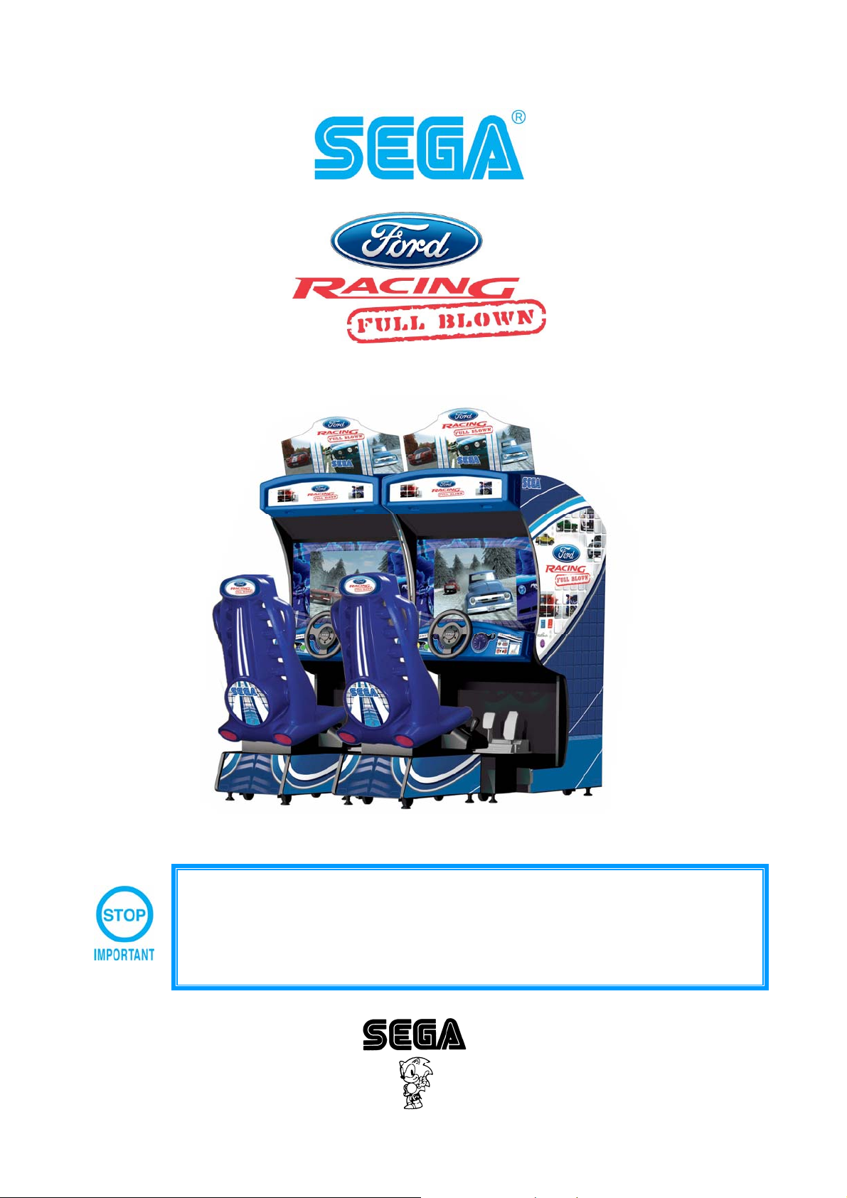
TWIN DRIVING CABINET
• Before using this product, read this MANUAL carefully to understand the contents
stated herein.
• After reading this MANUAL, be sure to keep it available nearby the product or
Manufactured in the UK by
somewhere convenient in order to be able to refer to it whenever necessary.
SERVICE MANUAL
Amusements Europe Limited
BEFORE USING THIS PRODUCT
To ensure the safe usage of the product, be sure to read the following before using the product. The
following instructions are intended for the use of QUALIFIED SERVICE PERSONNEL ONLY
reading and sufficiently understanding the instructions should any activity be carried out on the product.
Only qualified service personnel should carry out maintenance on the product.
Terms such as WARNING!, CAUTION, and IMPORTANT! Are used where an explanation is given which
requires special attention, depending on the potential risk. SEGA is not responsible for injury or damage
caused by use in a manner contrary to the instructions stated in this document. In order to prevent
accidents warning stickers and printed instructions are applied in the places where a potentially hazardous
situation relating to the product could arise. Be sure to comply with these warnings.
Indicates that mishandling the product by disregarding this warning will cause a
potentially hazardous situation which can result in death or serious injury.
Indicates that mishandling the product by disregarding this caution will cause a
potentially hazardous situation which can result in personal injury and or material
damage.
. After carefully
This is cautionary information which should be complied with when handling the
product. Indicates that mishandling the product by disregarding this will cause a
potentially hazardous situation which may not result in personal injury but could
damage the product.
• Perform work in accordance with the instructions herein stated.
Instructions for work are explained by paying attention to the aspect of accident prevention. Failing
to perform work as per the instructions can cause accidents. In the case where only those who
have technical expertise should perform the work to avoid hazardous situations, the instructions
herein state that the service person(s) should perform such work.
• Be sure to turn off power before working on the machine.
To prevent electrical shock, be sure to turn off power before starting work in areas in which which
the service person(s) touches the interior of the product. If the work has to be performed with the
power-on status, the instructions herein will state that only a qualified service person(s) should
perform such work.
• Ensure that the Power Supply used is equipped with an Earth Leakage Breaker.
This product does not incorporate an Earth Leakage Breaker. Using a power supply which is not
equipped with an Earth Leakage Breaker may cause a fire or serious injury.
• Be sure to use fuses which meet the specified rating.
Using fuses exceeding the specified rating can cause a fire and / or cause a n electric shock.
• Specification changes, removal of equipment, conversion and/or addition, not designated by
SEGA are not permitted and will invalidate this product’s CE conformity.
The parts of the product also include any warning labels or safety covers for personal protection
etc. A potential hazard will be created if the machine is operated while any parts have been
removed. Should any doors, lids or protective covers be damaged or lost, do not operate the
product. SEGA is not liable in any whatsoever for any injury and/or damage caused by specification
changes not designated by SEGA.
• When handling the monitor, be very careful. (Applies only to product with monitor).
Some of the monitor (TV) parts are subject to high tension voltage. Even after turning off the power
some components are still occasionally subject to high tension voltage. Monito r repair and
replacement should be performed by qualified service engineers only.
i

• Install and operate the machine only in places where appropriate lighting is available,
allowing warning stickers to be clearly read.
To ensure maximum safety for both customers and operators, stickers and printed instructions
describing potentially hazardous situations are applied to places where accidents co uld occur.
Ensure that where the product is operated has sufficient lighting to allow any warnings to be read. If
any sticker or printed warning is removed or defaced, do not operate the machine, until it has been
replaced by an identical item.
Before installing the product, check for the Electrical Specification Sticker, SEGA product s have a sticker on
which the electrical specifications are detailed. Ensure that the product is compatible with the power supply
voltage and frequency requirements of the location in which the machine is to be installed.
When installing this equipment ensure the socket outlet is near the machine and is easily accessible.
In cases where commercially available monitors and printers are used only the contents relating to this
product are stated in this manual. Some commercially available equipment has functions and reactions not
stated in this manual. Read this manual in conjunction with the specific manual of such equipment.
Descriptions contained herein may be subject to change without prior notification.
The contents described herein are fully prepared with due care. However, should any question arise or
errors be found please contact SEGA.
INSPECTION IMMEDIATELY AFTER TRANSPORTING THE PRODUCT TO LOCATION
Normally, at the time of shipment, SEGA products are in a state which allow for immediate usage after
transportation to location. Nevertheless, an irregular situation may occur during transportation. Before
applying power to the product, check the following points to ensure that the procuct has been transported in
a satisfactory status.
• Is there any external damage to the machine i.e. dents, cuts or cracks?
• Are the castors or leg adjusters damaged?
• Do the power supply voltage and the frequency of the machine meet the requirements of the
location?
• Are all wiring connectors correctly connected and secure?
• Are the power cables undamaged?
• Do the fuses meet the specified rating?
• Are all accessories available?
• Can all doors be opened and closed and locked with the keys provided?
ii

CONTENTS
SPECIFICATIONS........................................................................................................................................1
INTRODUCTION TO THIS MANUAL...........................................................................................................1
1. HANDLING PRECAUTIONS.................................................................................................................3
2. PRECAUTIONS REGARDING LOCATION AND INSTALLATION.......................................................5
3. OPERATION..........................................................................................................................................7
4. NAME OF PARTS..................................................................................................................................9
5. ACCESSORIES...................................................................................................................................10
6. FUSES.................................................................................................................................................11
7. ASSEMBLING WITH PRECAUTIONS................................................................................................12
8. PRECAUTIONS TO BE TAKEN WHEN MOVING THE MACHINE....................................................23
9. BASIC CONTENTS OF THE GAME ...................................................................................................24
10. EXPLANATION OF TEST AND DATA DISPLAY................................................................................25
10.1. VTS BOARD – SWITCHES AND COIN COUNTER....................................................................26
10.2. TEST MODE.................................................................................................................................27
10.3. SYSTEM INFORMATION.............................................................................................................28
10.4. UGCI TEST...................................................................................................................................29
10.5. INPUT TEST.................................................................................................................................30
10.6. CALIBRATION TEST ...................................................................................................................31
10.7. OUTPUT TEST.............................................................................................................................32
10.8. COIN TEST...................................................................................................................................33
10.9. SOUND TEST...............................................................................................................................34
10.10. CRT TEST....................................................................................................................................35
10.11. DRIVE BOARD TEST...................................................................................................................36
10.12. BOOKKEEPING ...........................................................................................................................37
10.13. CLOCK SETTINGS ......................................................................................................................40
10.14. NETWORK TEST.........................................................................................................................41
10.15. GAME TEST MODE.....................................................................................................................42
11. HOW TO PLAY....................................................................................................................................43
12. UPGRADES.........................................................................................................................................54
13. HANDLE MECHANISM.......................................................................................................................55
13.1. REMOVING THE CONTOL PANEL.............................................................................................55
13.2. REPLACING AND ADJUSTING THE HANDLE’S V.R. ...............................................................56
13.3. GREASING...................................................................................................................................57
14. SHIFT LEVER......................................................................................................................................58
14.1. REMOVING THE SHIFT LEVER..................................................................................................58
14.2. SWITCH REPLACEMENT ...........................................................................................................59
15. ACCELERATOR & BRAKE.................................................................................................................60
15.1. ADJUSTING AND REPLACING THE V.R. ..................................................................................60
16. COIN SELECTOR................................................................................................................................62
17. MONITOR............................................................................................................................................63
17.1. CAUTIONS CONCERNING THE SAFETY ISSUES WHEN HANDLING THE MONITOR..........63
17.2. CAUTIONS TO BE AWARE OF WHEN CLEANING THE CRT SURFACES..............................64
17.3. ADJUSTING THE PICTURE........................................................................................................65
18. REPLACEMENT OF FLUORESCENT LAMPS...................................................................................66
19. REPLACEMENT OF BUTTON LAMPS...............................................................................................68
20. GAME BOARD.....................................................................................................................................70
20.1. REMOVING THE GAME BD........................................................................................................70
20.2. GAME BOARD CONNECTIONS..................................................................................................72
21. UGCI BOARD......................................................................................................................................73
22. NETWORK PLAY ................................................................................................................................74
22.1. CONNECTIONS FOR NETWORK PLAY.....................................................................................76
22.2. NETWORK PLAY SETTINGS......................................................................................................77
23. COIN SETTINGS.................................................................................................................................78
23.1. VTS CREDIT BOARD OPTION SETTINGS ................................................................................80
23.2. PRICE OF PLAY SETTINGS UK .................................................................................................81
23.3. PRICE OF PLAY SETTINGS EURO............................................................................................82
24. DESIGNED RELATED PARTS ...........................................................................................................83
25. PARTS LIST ........................................................................................................................................84
25.1. TOP ASSY FORD RACING TWIN – FR00001UK.......................................................................85
25.2. ASSY MAIN 1P – FR-10001UK....................................................................................................86
25.3. ASSY CONTROL PANEL – FR-2000UK .....................................................................................88
iii

ASSY HANDLE MECHA – FR-2500UK.......................................................................................89
25.4.
25.5. ASSY SW PLATE – FR-2100UK..................................................................................................90
25.6. ASSY HEADER – FR-0200UK.....................................................................................................91
25.7. ASSY POP – FR-0270UK ............................................................................................................91
25.8. ASSY FAN UNIT DC – HDT-1530UK ..........................................................................................92
25.9. ASSY SEAT TWIN 1P – FR-5000UK...........................................................................................93
25.10. ASSY SEAT CABI – FR-5500UK.................................................................................................93
25.11. ASSY SEAT UNIT – FR-5600UK .................................................................................................94
25.12. ASSY AC BRKT MAIN – FR-0400UK ..........................................................................................95
25.13. ASSY AC BKT SUB – FR-0700UK ..............................................................................................95
25.14. ASSY PEDAL BASE L – FR-1100UK ..........................................................................................96
25.15. ASSY PEDAL BASE R – FR-1150UK..........................................................................................96
25.16. ASSY BRAKE & ACCEL – SPG-2200 .........................................................................................97
25.17. ASSY MAIN BD PC MASTER – FR-4500UK...............................................................................99
25.18. ASSY MAIN BD PC SLAVE – FR-4600UK ................................................................................100
25.19. ASSY COINCHUTE TOWER .....................................................................................................101
25.20. ASSY INSTALLATION KIT FR TWIN – FR-INST-TW................................................................102
26. APPENDIX A - ELECTRICAL SCHEMATIC .....................................................................................103
26.1. WIRE COLOURS .......................................................................................................................103
26.2. ELECTRICAL SCHEMATIC.......................................................................................................103
iv
SPECIFICATIONS
Installation space: 250cm (W) x 250cm (D)
Height: 217cm
Depth: 178cm
Width: 171cm
Weight: 500kgs (approx)
Rating: 3.5A MAX
Monitor type: SANWA 29” PFX FST
Monitor Operational Voltage: 230vac – 240vac
Display output: RGB
Operational Voltage 220vac – 240vav
Power Consumption 800W MAX
INTRODUCTION TO THIS MANUAL
This Owners Manual is intended to provide detailed descriptions together with all the necessary information
covering the general operation of electronic assemblies, electro mechanicals, servicin g control, spare parts,
etc. as regards to the product FORD RACING TWIN – FULL BLOWN.
This manual is intended for the owners, personnel and managers in charge of the operation of this product.
Only operate the product after carefully reading and sufficiently understanding the instructions. If the
product fails to function satisfactory, non-technical personnel should under no circumstances touch the
internal workings of this machine. Please contact where the product was pu rchased.
SEGA AMUSEMENTS EUROPE LIMITED
Suite 3a, Oaks house.
12-22 West Street,
Epsom.
Surrey.
KT18 7RG
Tel: +44 (0) 1372 731820
Fax: +44 (0) 1372 731849
1

DEFINITION OF THE QUALIFIED SERVICE ENGINEER AND MAINTENANCE PERSONEL
Non-technical personnel who do not have technical knowledge and expertise sh ould refrain
from performing such work that this manual requires. Only QUALIFIED SERVICE
ENGINEERS should carry out work either inside or outside the compass of this manual.
Failure to comply with this instruction may cause a severe accident or even death.
Ensure that all service, inspection repair work and troubleshooting is carried out by a
QUALIFIED SERVICE ENGINEER.
All other work i.e. cleaning and general upkeep of the machine (supplying data cards, repairing
coin jams or re-booting a machine) can be carried out by the LOCAL MAINTENANCE
PERSONEL.
“QUALIFIED SERVICE ENGINEER”
Those who participate in the design, manufacture, inspection, maintenance or service of
equipment at an amusement equipment manufacturer.
Those who have technical expertise with qualified certification regarding electricity, electronics
and or mechanical engineering and take part in a daily service and control of amusement
equipment.
“LOCAL MAINTENANCE PERSONEL”
Those who have experience in maintenance of amusements equipment and or vending
machines and also participate in daily routine work of general maintenance of the product.
2
1. HANDLING PRECAUTIONS
When installing or inspecting the machine, be very careful of the following points and pay
attention to ensure that the player can enjoy the game in safety.
Non-compliance with the following points or inappropriate handling running counter to the
cautionary matters herein stated can cause personal injury or damage to the machine.
• Before performing the work, be sure to turn the power off. Performing the work
without turning off the power can cause electric shock or short circuit. In the case
where work should be performed in the status of power on, this manual will state to
that effect.
• To avoid electric shock or short circuit, do not apply or disconnect power to the
machine in a quick or haphazard manner.
• To avoid electric shock, do not apply power to the machine with wet hand(s).
• Do not expose Power Cords or Earth Wires on the surface, (floor, passage, etc.) If
exposed, the Power Cord or Earth Wires are sustainable to damage. Damaged
Cords or Wires can cause an electric shock or short circuit which may lead to a fire
hazard.
• To avoid causing a fire and or electric shock, do not put objects on Power Cords or
Earth Wires.
• When or after installing the product, do not unnecessarily pull the Power Cord. If
damaged the Power Cord may cause an electric shock and or fire hazard.
• In case the Power Cord is damaged, ask for a replacement through where the
product was purchased or the office stated herein. Using a damaged Power Cord can
cause and electric shock or fire hazard.
• Be sure to perform correct earth checks and make sure that the machine is correctly
earthed. Inappropriate earthing of the product may cause electric shock or fire
hazard.
• Be sure to use fuses which meet the specified rating. Using fuses which exceed the
specified rating can cause electric shock, short circuit and or fire hazard.
• Ensure all connections are made fully. Connections which are not fully made may
cause electric shock or fire hazard.
• To avoid causing a fire hazard or an electric shock, do not make any unspecified
changes to the product by replacing or changing parts or components without the
express consent of SEGA.
• Be sure to make periodic maintenance checks as stated herein.
• Only a QUALIFIED ELECTRONICS ENGINEER is allowed to perform IC BOARD
inspection or analysis using a LOGIC ANALYSER. The use of a MULTIMETER is not
permitted on IC BOARDS.
• When cleaning the CRT surfaces, use a soft dry cloth. Do not apply chemicals such
as thinners, benzene, etc.
• The electronic parts on the IC BOARD could be damaged due to human body static
electricity. Before performing IC BOARD related work, be sure to discharge physically
accumulated static by discharging on a grounded metallic surface.
3
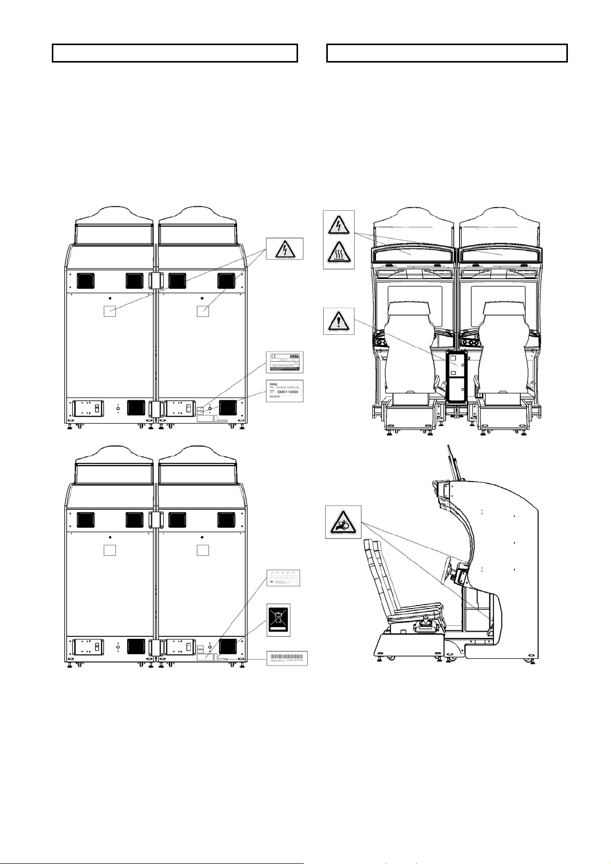
CONCERNING THE STICKER DISPLAY CONCERNING WARNING STICKERS
SEGA product has stickers describing the product
manufacture number (Serial Number) and electrical
specification. If you require service assistance you
will require the Serial Number. Identical machines
may have different parts fitted internally. Only by
quoting the Serial Number will the correct parts be
SEGA product has warning displays on stickers,
labels or printed instructions adhered/attached to
or incorporated in the places where hazardous
situations can arise. The warning displays are
intended for the accident prevention of customers
and service personnel.
identified.
4
2. PRECAUTIONS REGARDING LOCATION AND INSTALLATION
This product is an indoor amusement machine. Do not install it outside. Even indoors, avoid
installing in places mentioned below sp as not to cause a fire, electric shock, injury and or
malfunction.
• Places subject to rain or water leakage, or places subject to high humidity in the
proximity of an indoor swimming pool and or shower, bath etc.
• Places subject to direct sunlight, or places subjected to high temperatures such as in
the vicinity of heating units, etc.
• Places filled with inflammable materials or chemicals or any hazardous matter.
• Dusty places.
• Sloped surfaces.
• Places subjected to any type of violent impact.
• Vicinity of anti-disaster facilities such as fire escapes and fire extinguishers.
• The operating (ambient) temperature range is from 5 degrees centigrade to 40
degrees centigrade. Only in the cases where a projector is employed then the
temperature drops from 40 to 30 degrees centigrade.
• This appliance is not suitable for installation in an area where a water jet could be
used
LIMITATIONS OF USAGE REQUIREMENTS
• Be sure to check the electrical specifications. Ensure that this product is compatible
with the locations power supply voltage and frequency requirements. A plate
describing the electrical specifications is attached to the product. Non-compliance
with the electrical specification can cause fire or electrical shock.
• This product requires a RCD as part of the location facilities. Using them in a manner
not independent can cause an electric shock or a fire.
• Ensure that the indoor wiring for the power supply is rates at 7A or higher in areas
using 220 – 240VAC. Non-compliance with this may cause electric shock or a fire.
• Be sure to independently use the power supply equipped with an Earth leakage
breaker. Using a power supply without an Earth leakage breaker can cause a fire
when earth leakage occurs.
• Putting many loads on one electrical outlet can cause a generation of heat and a fire
may result from an overload.
• When using an extension cord, ensure that the cord is rated at 7A or higher. Using a
cord rated lower than the specified rating may cause a fire or electric shock.
5
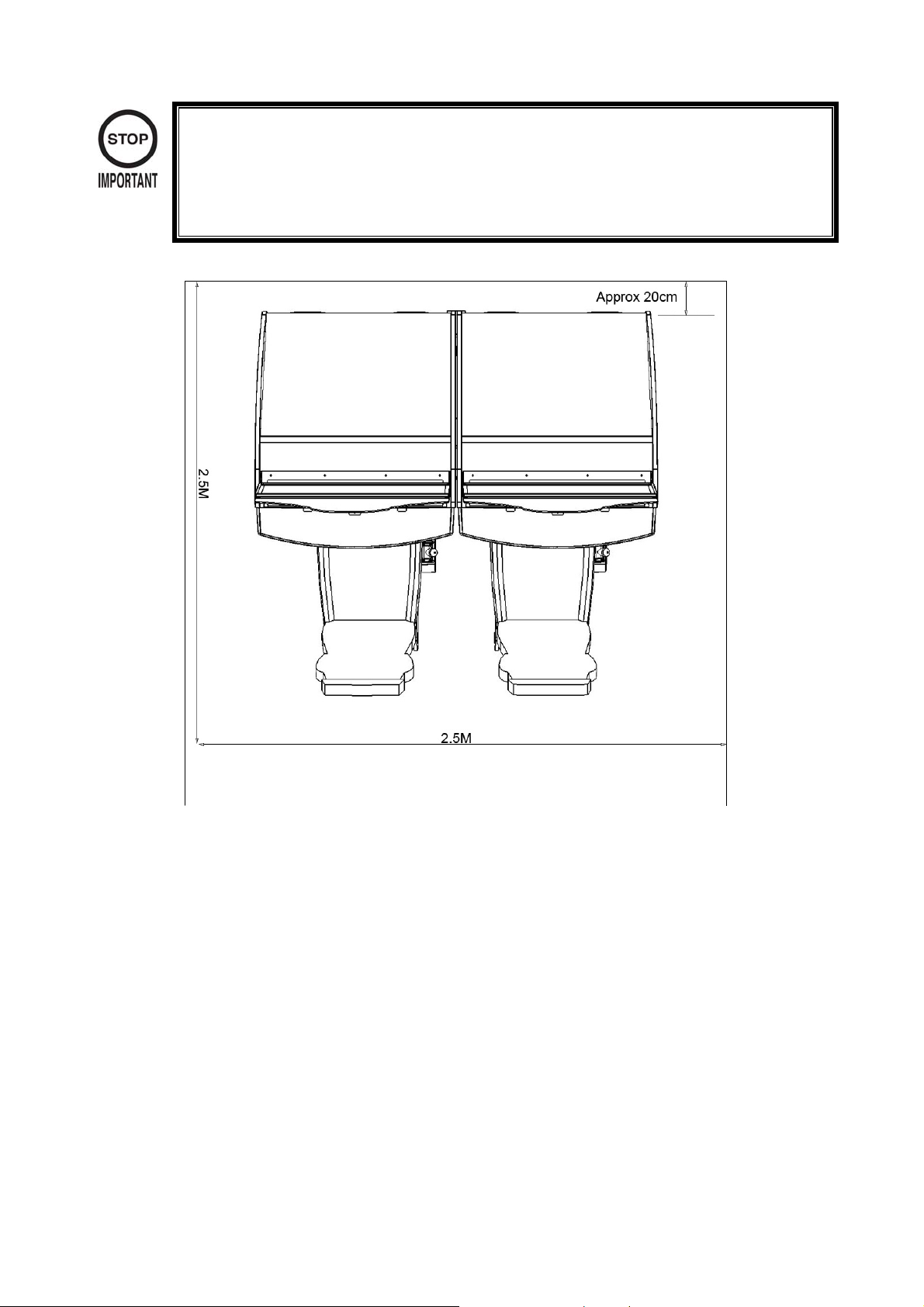
• Note that for transporting the machine to location the minimum necessary dimensions
required for opening (of doors, etc.) are 1.85M x 1.05M (without shipping pallet.).
• For the operation of this machine, secure a minimum area of 2.5M x 2.5M. For
ventilation, provide an approximately 20cm space between the rear part of the
cabinet and the wall.
6
3. OPERATION
PRECAUTIONS TO BE HEEDED BEFORE STARTING OPERATION
To avoid injury be sure to constantly give careful attention to the behaviour and manner of players and
spectators.
In order to avoid accidents, check the following before starting operation.
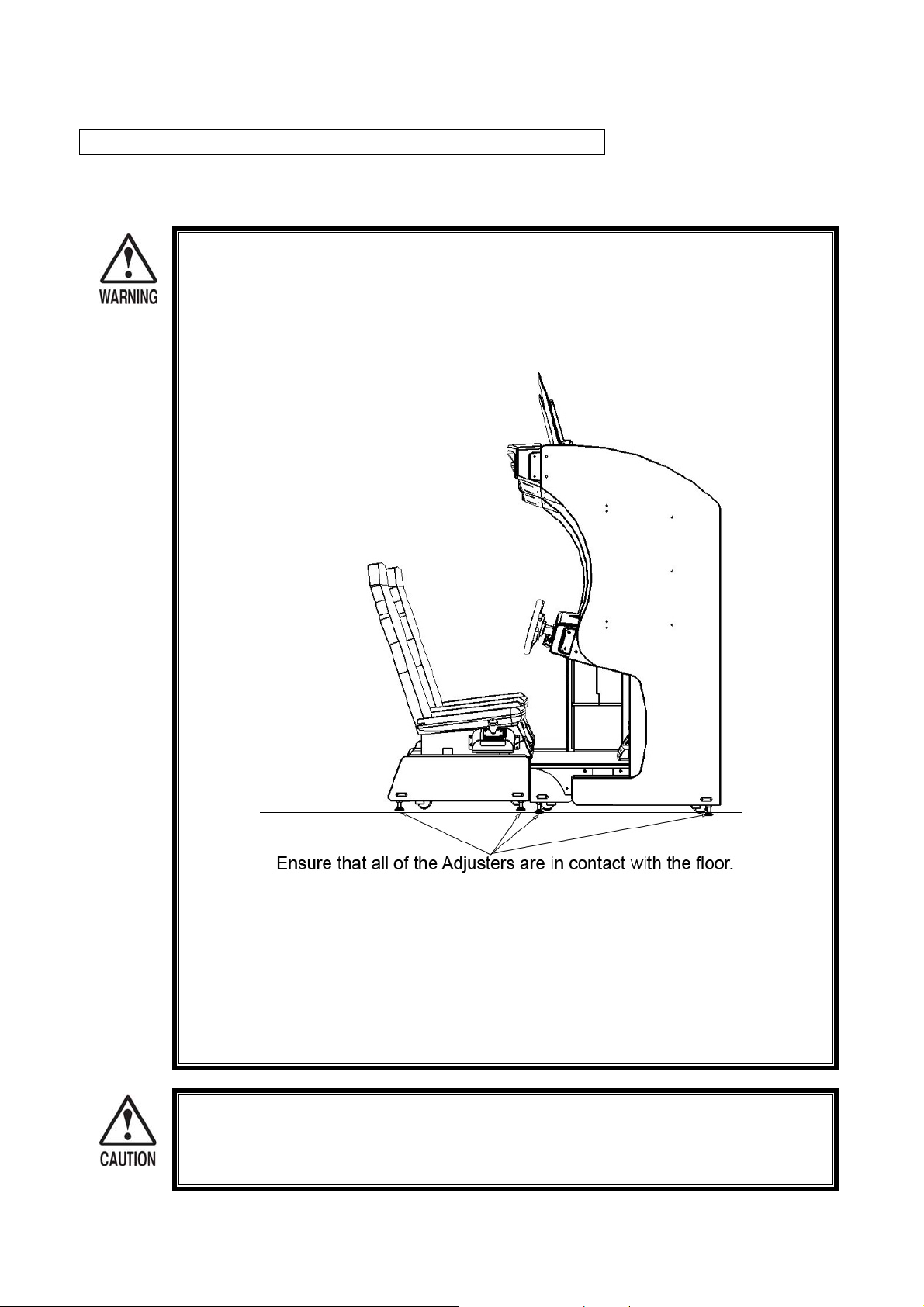
• Check if all of the adjusters are in contact with the surface. If they are not, the cabinet
may move and cause an accident.
• Do not put any heavy item on this product. Placing any heavy item on the product
can cause accidental injury.
• Do not climb on this product. Climbing on this product can cause an accident or
injury. To check the upper most part of this product, please you a step.
• To avoid electric shock, short circuit or damage, do not put the following items in the
periphery of this product.
Flower vases, flowerpots, cups or any vessels which can contain water or chemicals.
To avoid injury, be sure to provide sufficient space by considering the potentially crowde d
situation at the installation location. Insufficient installation space can cause the player to
come into contact with other resulting in injury.
7
PAYING ATTENTION TO CUSTOMERS
To avoid injury or confrontation between customers, be sure to constantly give careful attention to the
behaviour and manners of the players and visitors.
• To avoid electric shock and or short circuit, do not allow customers to put hands or
fingers or any other extraneous matter into the openings of the product.
• To avoid injury from items falling from the machine, immediately stop customers from
either putting items on top of the product or leaning against or climbing on the
product.
• To avoid electric shock and or short circuit, do not allow customers to unplug the
power cause at any cause.
• To avoid injury resulting from items falling from the machine, instruct the player not to
place items or drinks onto the product.
• Immediately stop such violent acts as hitting or kicking the product. Such violent acts
can cause damage to the product or injury to the player or observer.
8
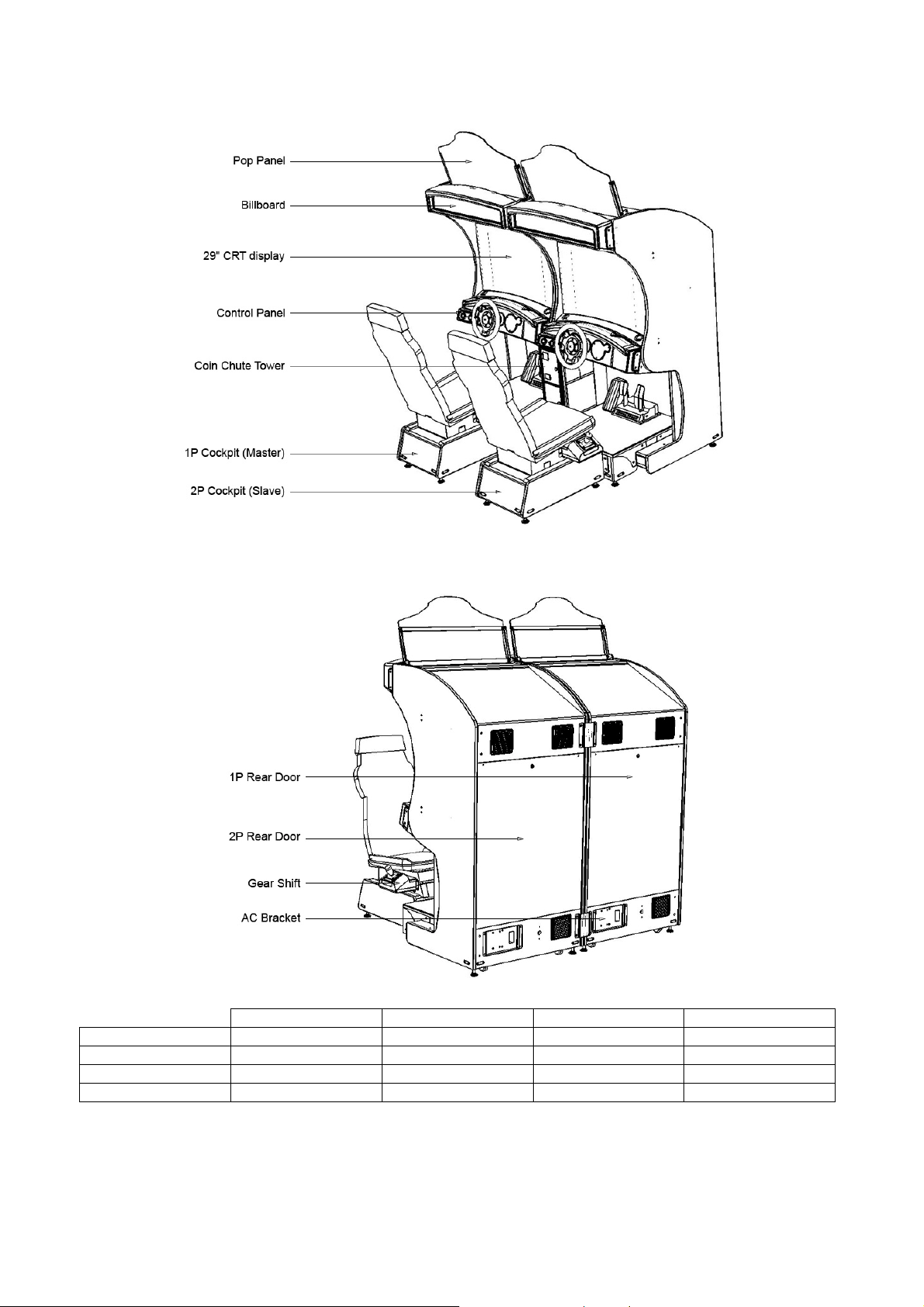
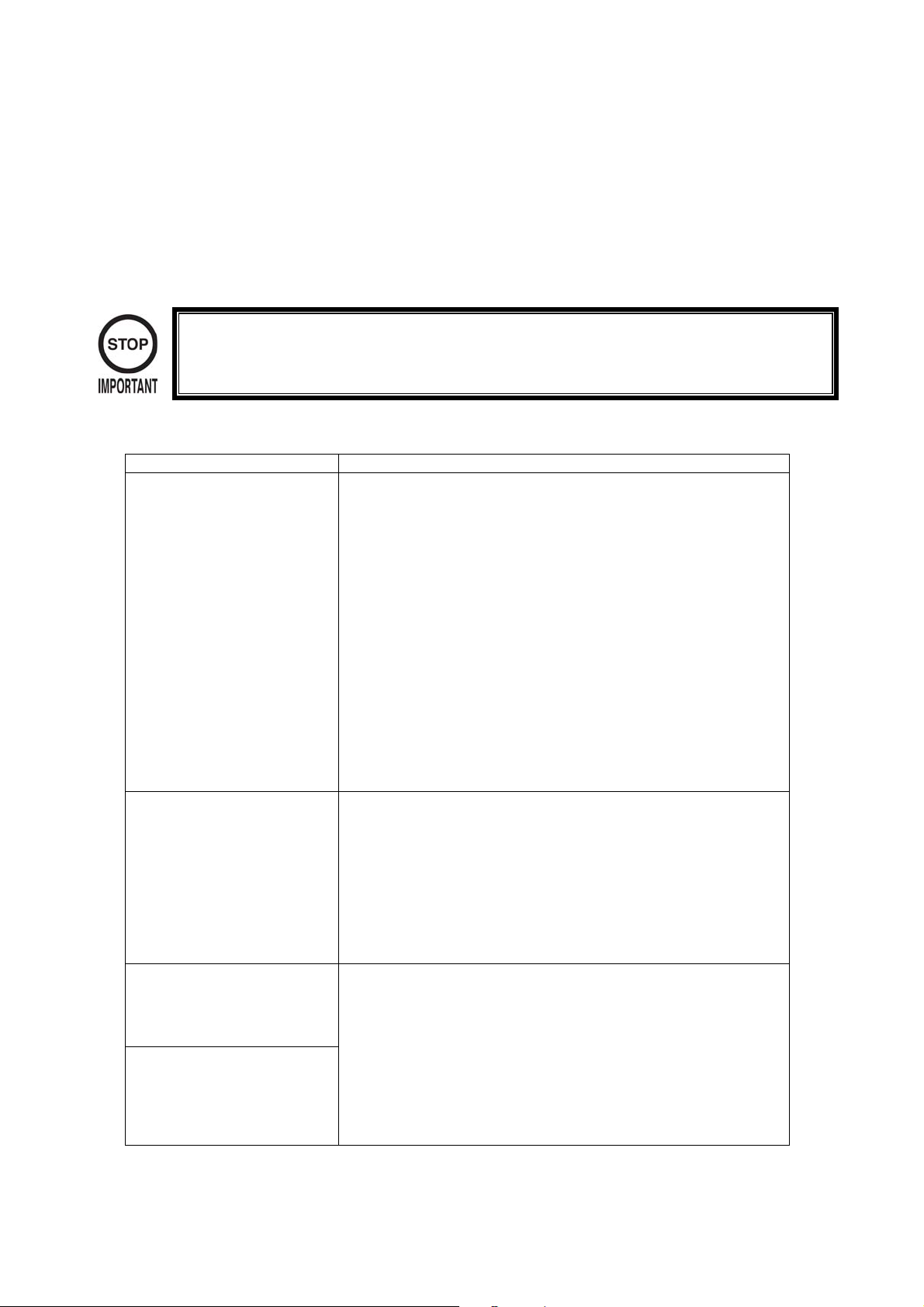
4. NAME OF PARTS
Width Depth Height Weight
Cockpit (per seat) 852mm 1630mm 1790mm
Coin Chute Tower 220mm 300mm 550mm 15kg
Pop Panel 800mm - 430mm
When Assembled 1713mm 1624mm 2200mm
9
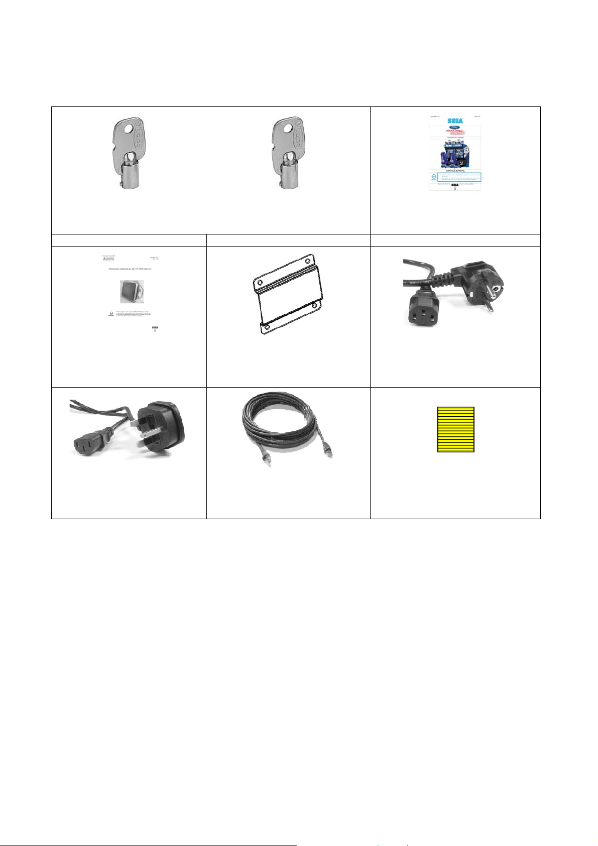
5. ACCESSORIES
When transporting the machine to location, make sure that the following parts are supplied.
KEYS MASTER 9117 KEY TO DIFFER SERVICE MANUAL FR
For opening and closing service
doors
PT No 220-5575UK PT No 220-5574-110UK PT No: 420-FRSM-02UK
SERVICE MANUAL SANWA JOINT BKT REAR X 2 POWER CORD EUROPE
Sanwa CRT Service Manual
PT No: 420-5827-91UK PT No: FR-0013UK
POWER CORD UK NETWORKING CABLE 5MTRS STICKER C EPILEPSY
Used for applying power to the
machine in UK
PT No: 600-7269-0500UK PT No: 440-CS0186UK
For opening and closing secure
For adjoining the two Display
cabinets
Used to for linking up more that
one twin cabinet
door
This Manual
Used for applying power to the
machine in Europe (not UK)
Apply to a visible area using the
location language
10

6. FUSES
• Never touch places other than those specified. Touching places other than those
specified can cause electric shock or short circuit. Disconnect the machine from the
Part Number Location Description
514-5078-3150 RND-838-001 FUSE BD CAB 1&2 3.15A T CERAMIC 20MM
514-5078-5000 RND-838-001 FUSE BD CAB 2 5A T CERAMIC 20MM
514-5078-10000 FR-0400UK AC BRKT 10A T CERAMIC 20MM
514-5079-3000 FR-838-001UK MOTOR CONT BD 3A SLO-BLO GALSS 32MM
514-XXXX-5000 838-CA-150 AUDIO AMP 5A AUTO FUSE
supply before attempting the replacement of any fuse.
• Only QUALIFIED PERSONNEL should replace fuses.
• Only replace fuses with ones of the same value and type.
There are also fuses located on the Monitor PCB. Please refer to the separate Monitor manual supplied to
reference these fuses.
11
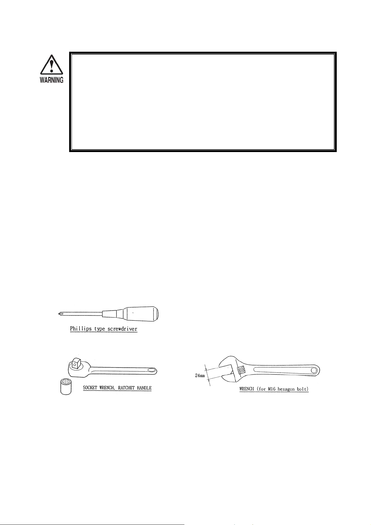
7. ASSEMBLING WITH PRECAUTIONS
• Perform assembly work by following the procedure herein stated. Failing to comply
with the instructions can cause electric shock.
When carrying out the assembly work, follow the procedure as laid out in this manual. Do not skip any
stages as injury may occur if the machine in not installed in the correct sequence.
1. Assembling 1 and 2 player cockpit.
2. Securing the machine into location.
3. Installing the Pop panel.
• Assembling should be performed as stated in this manual. Since this is a complex
machine, erroneous assembling can cause electric shock, machine damage and or
impair functionality.
• When assembling, be sure to be accompanied by another person. Depending on the
work involved – there are some cases where two people are required. If only one
person carries out the work alone, then it is possible that injury may occur, or
damage to the product.
• Ensure that all connectors are accurately connected. Incomplete connections may
cause electric shock or fire hazard.
4. Installing Power Cables.
5. Turning power ON.
6. Assembly check.
When assembling, make sure that tools such as a Phillips type screwdriver, wrench (for M16 hex) and a
socket wrench to suit M8 (13mm) are available.
12

• Only tighten fixings when all fixing are in place. If the fixings are tightened as the
work progresses, it might not be possible to align the final fixings.
ASSEMBLING 1 AND 2
B
B
Step 1.
Place the two cockpits side by side
so that the artwork is facing
outwards on both units. The 1P
cabinet has the power cord at the
left hand side as viewed facing the
monitor.
PLAYER COCKPITS
Step 2.
Install the coin chute tower in
between both cabinets. Open both
coin doors and remove the cash
box and the cash box base plate.
13
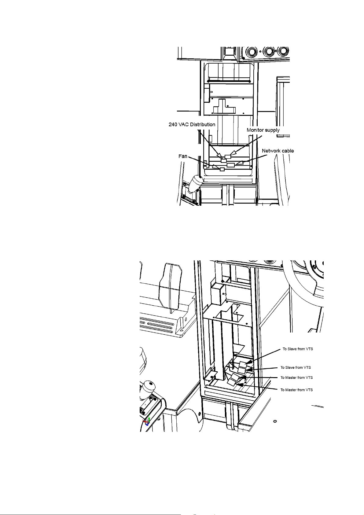
Step 3.
Making sure that there are no
trapped wires, make the 4 (four)
connections between both Master
and Slave cabinets.
Step 4.
Make the remaining 4 (four)
connections between the Coin
Tower and Master and Slave units.
Connect the 2 Earth ring terminals
to the M4 stud on the floor of the
Coin Tower and secure.
14
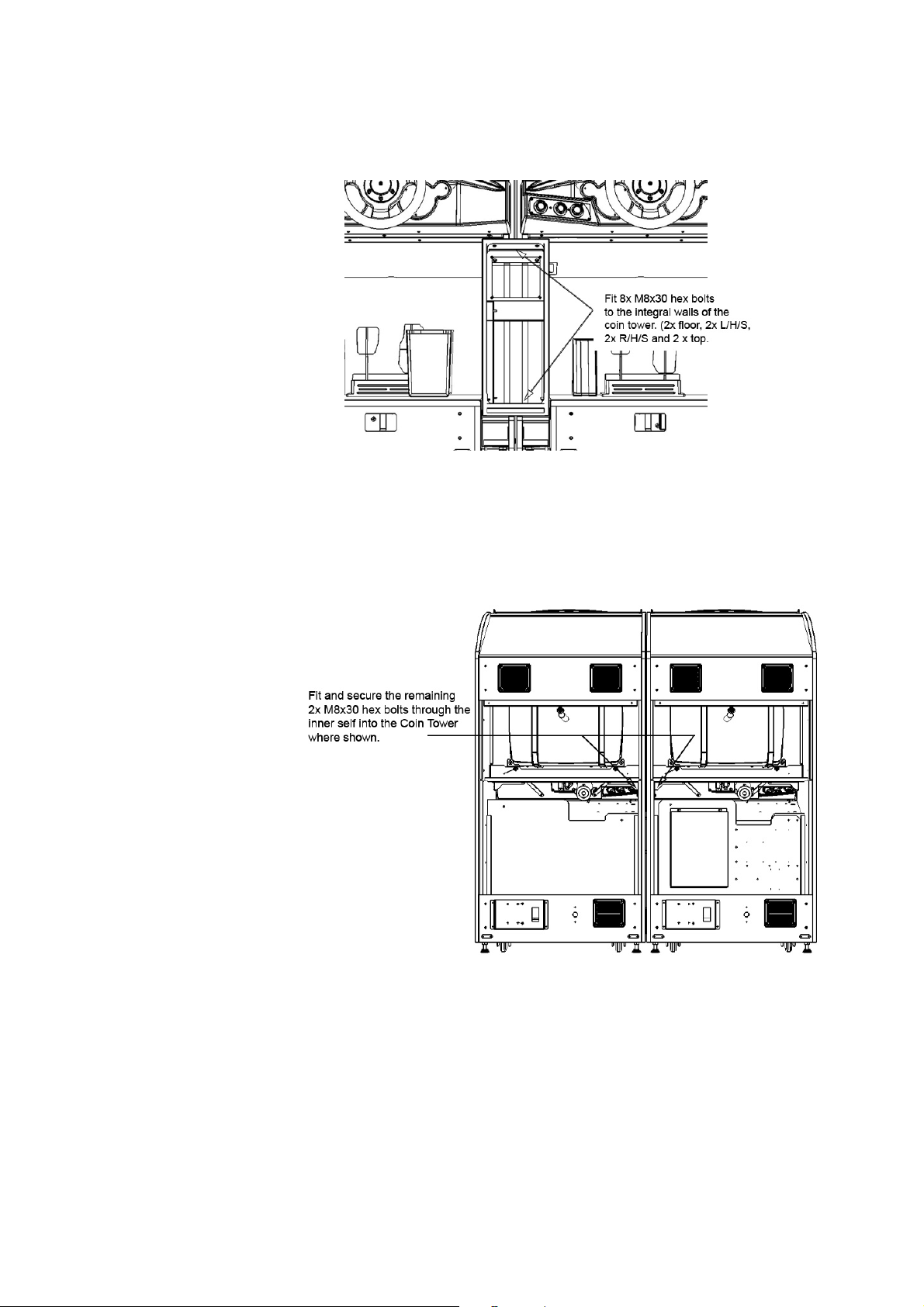
Step 5.
Fix the coin tower to both
cabinets by applying 8x
M8x30 Hex Bolts (supplied)
to the integral part of the
tower.
Step 6.
Fit and secure the
remaining 2x M8x30 Hex
Bolts into the Coin Tower
from inside both machines
as show.
15
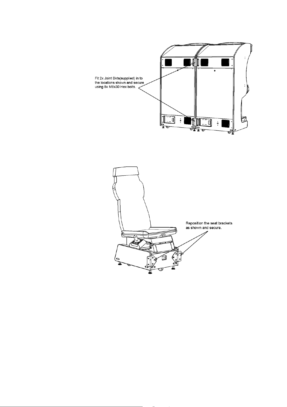
Step 7.
Apply the 2x Join Brackets
(FR-0013UK) to the
outside of the cabinets as
shown.
Secure using the 8x M8x30
bolts (supplied).
Step 8.
The seat brackets are
attached to the seat
cabinet but will be inverted
for transportation.
Reposition the brackets so
that they depict the figure
to the right and secure with
the same fixings.
16
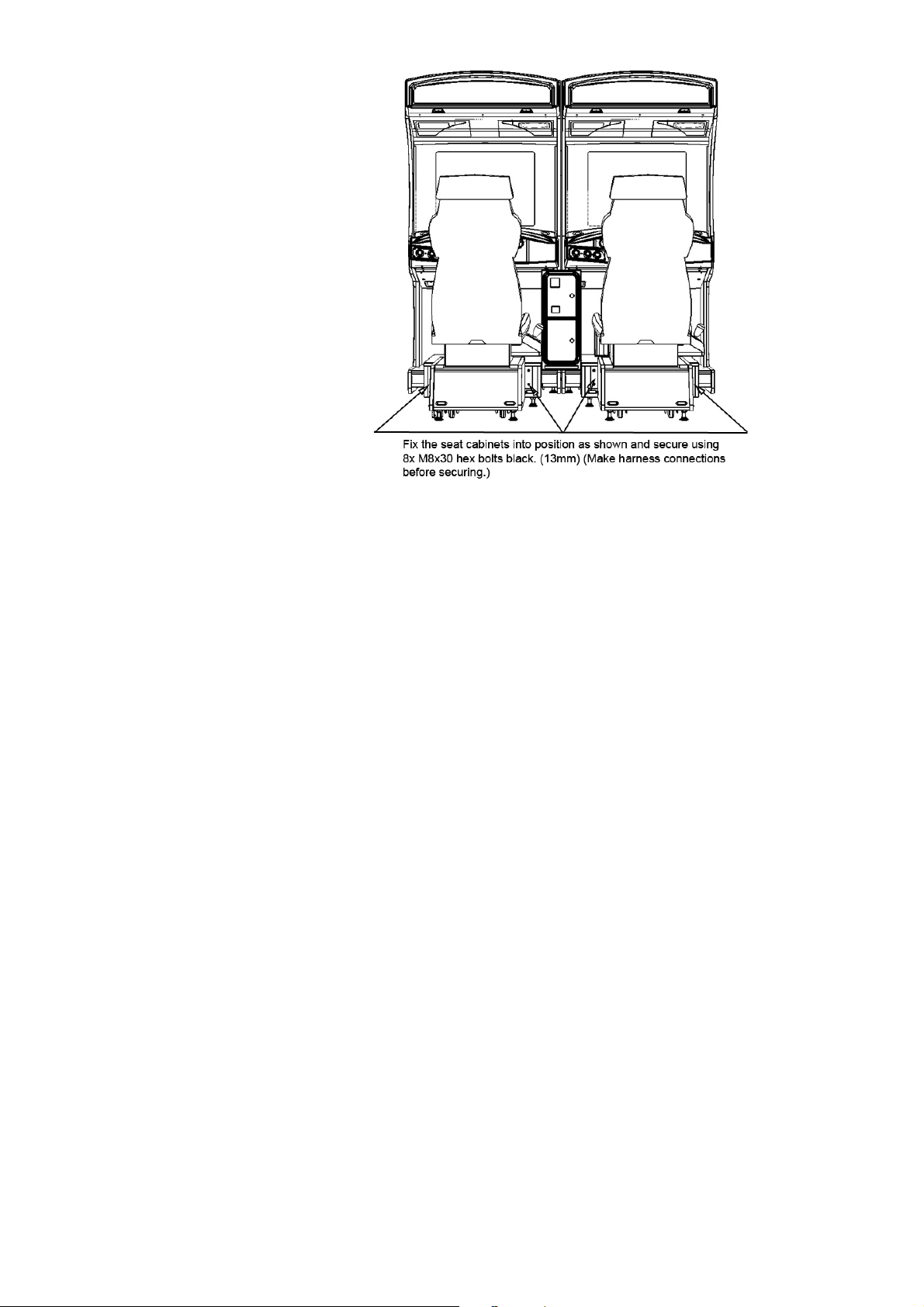
Step 9.
Offer the seat cabinet up to
the display cabinet. Before
attaching both cabinets,
make sure that the seat
harness has been
connected to the main
harness. Once connection
has been established,
secure both seat cabinets
to the main cabinets using
4x M8x30 Hex Bolts Black.
Step 10. Tighten ALL bolts in their present location using a 13mm hex driver.
17
C
C
Step 1.
Move the machine to the
installation position. When
installing the machine against or
close to a wall, be sure to secure a
space to ensure player can safely
enter and exit the machine without
obstruction.
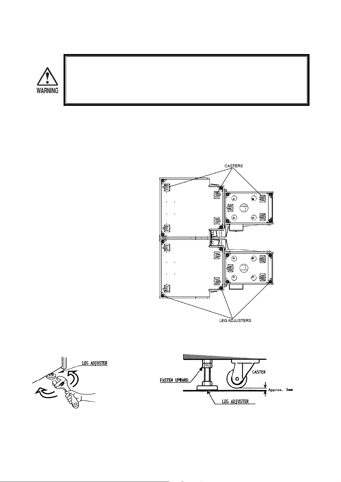
Step 2.
Bring all leg adjusters down to
make contact with the floor. Using
a Wrench or spanner adjust the
leveller so that the casters rise
approximately 5mm from the floor.
Step 3.
Once all adjusters have been
adjusted and the machine is made
level, fasten the adjuster nut
upwards to secure the height of the
adjuster.
SECURING THE MACHINE INTO LOCATION
• Make sure that all of the adjusters are in contact with the floor. If they are not, the
cabinet may move and cause an accident or injury.
• Be sure to use two people to perform this work. Depending on the specific work,
The machine has 14 casters (7 per unit) and 16 leg adjusters (8 per unit). When the
installation position is determined, bring the adjusters in contact to the floor. Make the
adjustment so that the casters rise from the floor approximately 5mm. Also make sure that
the machine positioning is level.
there are some cases in which working by one person alone may cause an accident
or injury.
After securing the height of the adjusters, tighten all of the hexagon bolts which were fastened temporarily
as per step 1.
18
D
D
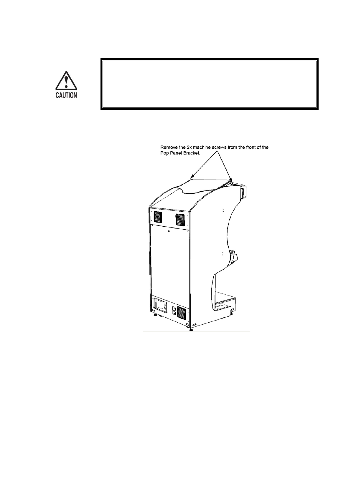
INSTALLING THE POP PANEL.
• To perform work safely and securely, be sure to use a step which is in a
secure and stable condition. Performing work without a step or a step
which is not in a suitable condition may cause and accident or injury.
Step 1.
19
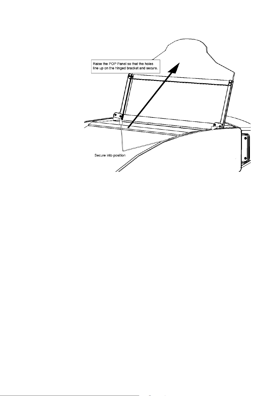
Step 2
20
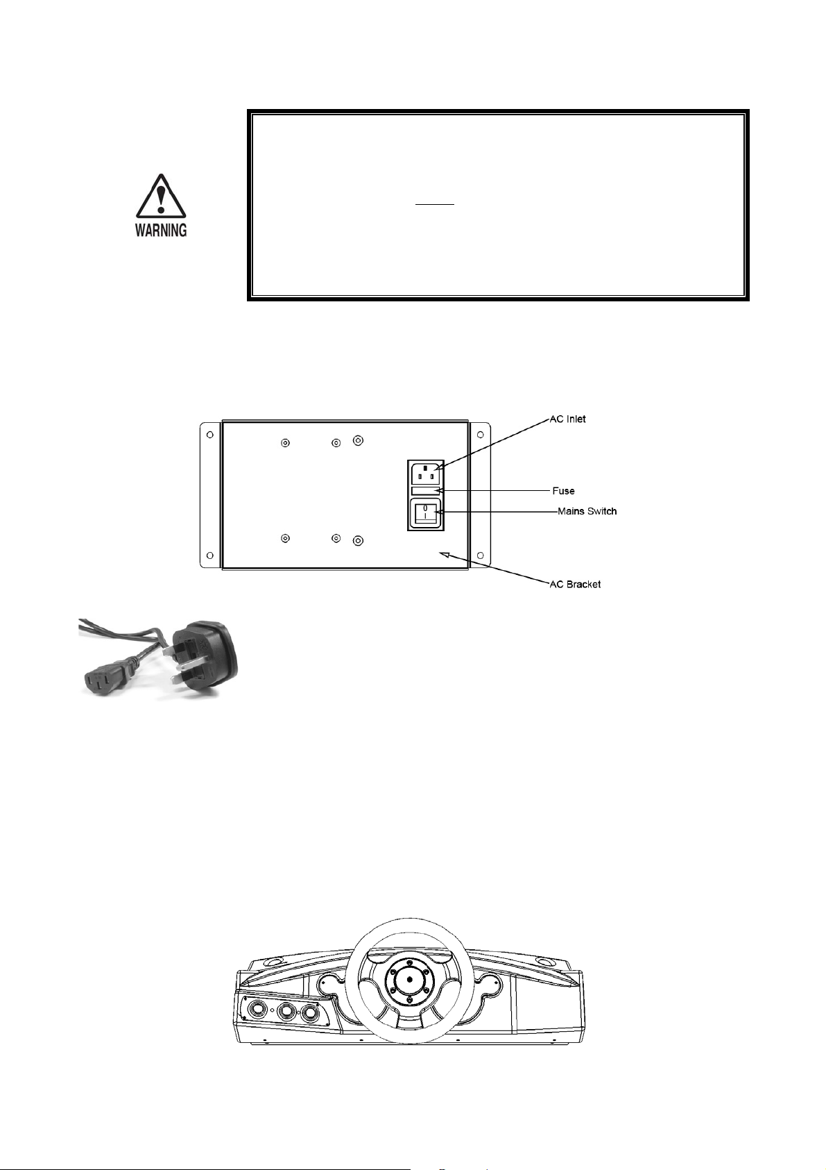
E
E
The AC unit is mounted on the 1P COCKPIT. The AC unit incorporates the Main SW, Fuse, Primary Earth
Terminal and the AC Inlet socket.
INSTALLING THE POWER CABLES
• Be sure to use an independent power supply socket equipped with an
Earth Leakage Breaker. Using a power supply without an Earth
Leakage Breaker can lead to a fire or potential shock hazard.
• THIS PRODUCT MUST
• Ensure that the power cord is not exposed on the surface. If exposed
the cord may be susceptible to damage. If damaged, the cord may
cause electric shock or fire hazard. Ensure that the power cord is not
in the customers walk way or that the cord has a protective cover.
BE EARTHED.
F
F
Firmly insert the 3 pin power plug (UK) or 2 pin power plug (EU) into the
socket outlet. Insert the opposite end of the power cord into the AC inlet of the
AC bracket.
Install suitable protective wire covering for the power cord to prevent any
accidents or injury (not supplied).
TURNING THE POWER ON
Turning the AC UNIT main switch on will cause the machine to start the POWER ON check
and NETWORK check automatically.
In the power on check the steering wheel may turn. DO NOT interrupt the steering wheel as it
moves as it may cause steering problems during the game.
During network checking “PLEASE WAIT” flashes on screen. When the network checking has
finished, the game demo mode will start. If after initialization connection has not been
established, check the network connections between cabinets and repe at process.
21
G
G
In the TEST MODE, ensure that the assembly has been made correctly and the IC BD
ASSEMBLY CHECK
is satisfactory. In the TEST MODE, perform the following tests.
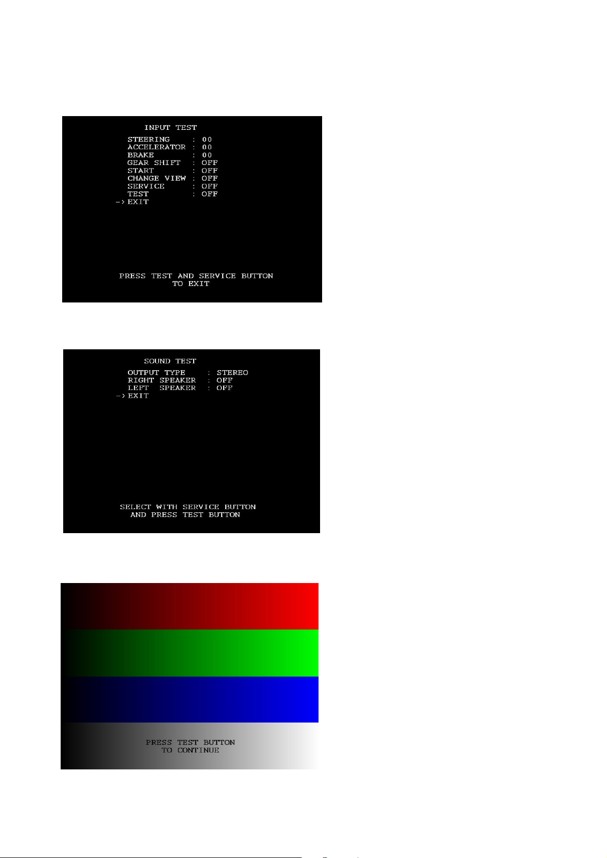
Select the INPUT TEST from the SYSTEM
MENU (left screen). This screen enables the
user to test individual input to the game.
Once all input devices have been tested and
proved to be in working order, press the test
and service buttons to exit.
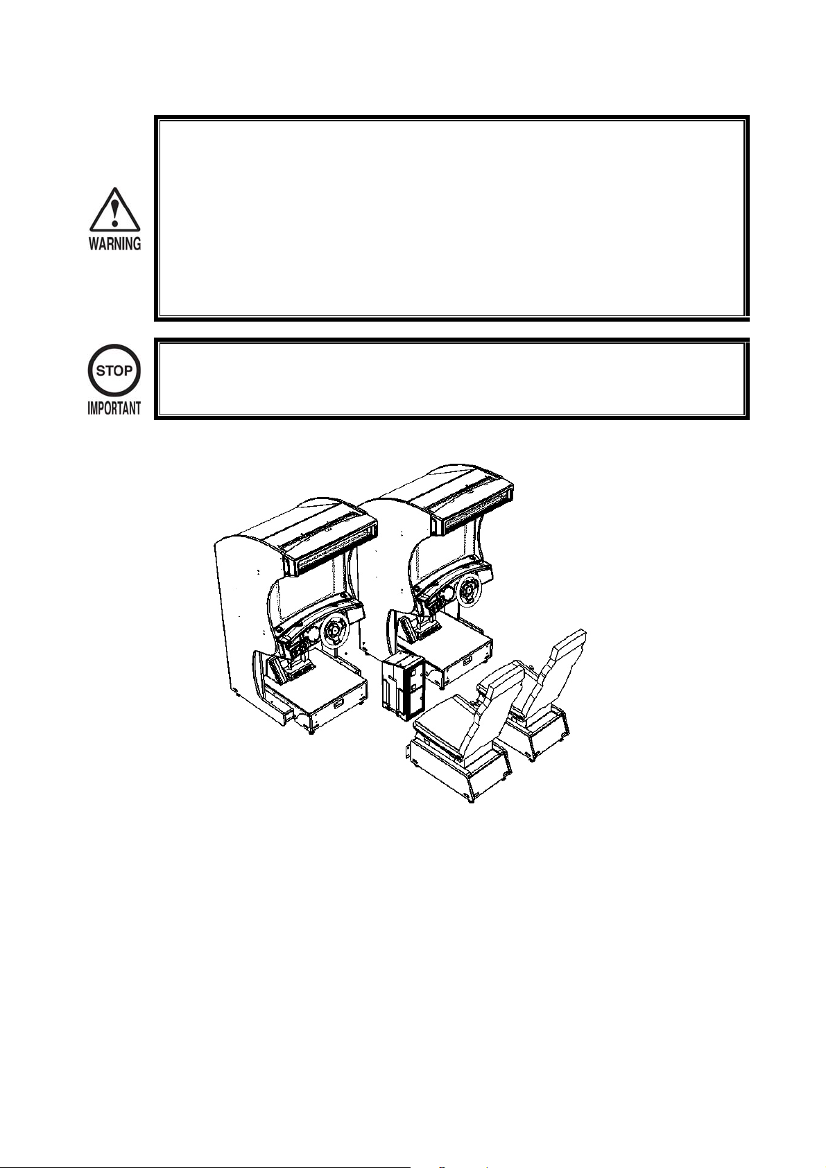
In the SOUND TEST, use the service switch
to access left and right speaker outputs.
Check that both speakers are working
satisfactory and that the sound levels are set
to am appropriate level.
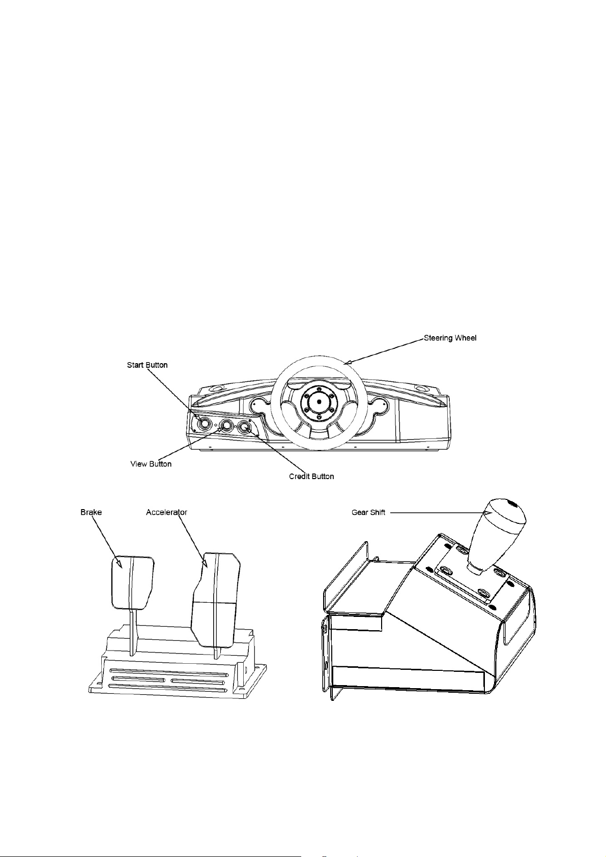
In the SYSTEM TEST MODE MENU select
the CRT TEST. Although the monitor
adjustments have been made before
shipping, make sure that the image covers
the screen without loss of graphics. If
necessary, adjust the monitor.
Use the DEGAUSE switch if necessary to
bring the colours back into perspective.
22
8. PRECAUTIONS TO BE TAKEN WHEN MOVING THE MACHINE
• When moving the machine, be sure to unplug the power cord from both the wall and
machine ends. Moving the machine whilst either plug is inserted can cause either
and accident or injury by electric shock.
• When moving the machine along the floor, retract the Adjusters and ensure that the
casters make contact with the floor. During transportation, pay careful attention so
that the castors do not manoeuvre over power cables. Damaging power cables can
cause electric shock or a short circuit hazard.
• When moving the machine, do not push the cabinets with the seat fixed. Moving the
cabinets whilst the seat are fixed may cause damage to the fixing positions of the
seat.
• When transporting the product in places where steps are used to gain access,
disassemble the seat units from the main cabinets as damage can occur at the
adjoining positions.
When transporting the machine in places where steps have to be contended with, break the machine down
into individual parts to make transit easier.
23
9. BASIC CONTENTS OF THE GAME
The following outlines basic routines to check whether the product is functioning satisfactory. If
there is a deviation between what is explained in this section and the actual results of the machine
then immediately look into the cause of fault and eliminate the cause to ensure satisfactory
operation.
During the attract mode, the START button will flash, the BILLBOARD lamps will be lit and audio
will be emitted from both left and right speakers. (There are no speakers in the seat assembly).
1. Sit in the Cockpit. The seat can be adjusted in either a forward or reverse positions. The
lever is located on the lower right hand side in front of the seat. Pull this lever to make
adjustments to the seat.
2. Insert a coin(s). The number of credit(s) is displayed in the bottom left hand side of the
screen.
3. Press the green “CREDIT” button and the credit will transfer from the VTS BD to the
cabinet which is calling for credit. A visual indication of credits displayed at the bottom left
corner of the screen will increment by the amount of credits set. “PRESS START” will
appear on screen.
4. Press the “START” button and the game will start by employing the driver to select certain
criteria’s i.e. type of car, type of course.
24
10. EXPLANATION OF TEST AND DATA DISPLAY
By operating the buttons located on the VTS BD will enable the SYSTEM and GAME TEST
MODES. When installing the machines, collecting cash or when the machine does not perform
correctly, initiate a test sequence as explained in this section of the manual. The following outlines
each test mode and explains in detail the movement throughout the menus.
• ONLY A QUALIFIED SERVICE ENGINEER SHOULD MAKE ANY AMMENDMENTS
TO THE CRITERIAS LISTED WITHIN THE SYSTEM TEST MENU.
ITEMS DESCRIPTION
MACHINE INSTALLATION
PERIODIC SERVICING
When the machine is installed, perform the following:
1. Check that each setting is set to the factory setting as
per the time of shipment.
2. In the INPUT TEST mode, check each switch and VR
for operation.
3. In the SOUND TEST check the operation of both front
speakers.
4. In the CRT TEST check the adjustment of the picture
and adjust if necessary.
Periodically perform the following tests:
1. In the INPUT TEST mode, check the CONTROL
devices and buttons.
2. In the SOUND TEST perform a sound check.
MONITOR
DATA CHECK
In the monitor check screen, check to see if the MONITOR
adjustments are made correctly.
Check such data as game play time and histogram and adjust
difficulty levels if necessary.
25
 Loading...