

Page 1

TM
OWNER’S MANUAL
MODEL
Page 2

Page 3

FOR YOUR SAFETY: READ BEFORE USING THE PRODUCT
To guarantee safe operation, read the following prior to powering on the product. These instructions are intended for the users, operators and personnel in charge of the operation of the product. Before handling, carefully read and understand all cautionary labels on the product. Follow
all precautions and handle the product accordingly. Keep the manual near the product for future
reference.
It is important to properly understand the degrees of hazard communicated by the cautionary labels on the product. These labels require special attention: DANGER, WARNING, CAUTION, etc.
Indicates that mishandling the product by disregarding this symbol will lead to
severe injury or death.
DANGER
Indicates that mishandling the product by disregarding this symbol will lead to
a potentially hazardous circumstance which can result in serious injury
or death.
WARNING
Indicates that mishandling the product by disregarding this symbol will create a
slightly hazardous circumstance which can result in personal injury and/or
material damage.
CAUTION
For the safe and proper usage of the product, the following labels are used:
Indicates “HANDLE WITH CARE.” This label is used to avoid personal injury and
product damage. The label is displayed in places where the Owner’s Manual,
Serviceman Manual and/or Service Manual should be used as reference.
Indicates “PROTECTIVE GROUND TERMINAL.” Prior to powering on and
operating the equipment, securely connect the product to the Ground prior to
powering on and operating the equipment. (This step may be eliminated in
instances where the product uses a power cord with a ground connection.)
NOTE:
• Follow the instructions contained within this manual.
The instructions are designed to aid in the prevention of accidents. Failure to follow the enclosed
guidelines may result in product damage, personal injury and/or death. In the instances where
only a person with technical expertise should perform the work, the manual states that only the
site personnel should proceed with the work.
Page 4

• Power down and disconnect the power prior to working on the product.
To avoid electrical shock, it is important to power off the product and disconnect from the power
source in all instances where the work requires direct contact with the interior of the product. In
the instances that the work requires a power-on status, the manual will clearly state it.
• Connect the Ground Terminal.
(This step may be eliminated in instances where the product uses a power cord with a
ground connection.)
This product contains a Ground Terminal. During installation, it is important to securely connect
the Ground Terminal with the proper indoor ground terminal through the use of a grounded cable.
If the product is not properly grounded, the user is exposed to potentially hazardous electrical
shock. After every instance of performing work, ensure that the Ground Terminal is once again
securely connected.
• Use specied fuses
(Only for products that use fuses.)
Using fuses that exceed the required rating may cause re and electric shock.
• Specication changes (including but not limited to equipment relocation, conversion,
and addition) not designated by the manufacturer, Quasimoto Interactive, Inc., are not permitted.
All parts of the product, including safety warning labels, should not be removed. It is hazardous to
operate the product after removing parts and/or modifying the circuits. In the event that any doors,
covers, lids, and/or protective parts are damaged or lost, immediately cease product operation.
Promptly contact the distributor from which the product was purchased for a replacement component. Quasimoto Interactive, Inc. shall not be held responsible for any accidents or compensation
for damage to a third party that are the result of product specications not designated by Quasimoto Interactive, Inc.
• Make sure the product meets the correct Electrical Specications
Prior to installing the product, check for Electrical Specications. Quasimoto Interactive, Inc. products are labeled with an Electrical Specications description. Make sure that the product is com-
patible with the power supply voltage and frequency requirements of the location. Any variance on
the Electrical Specications at the location from those contained on the product’s description label
may cause a re and/or an electric shock.
• Use suitable lighting during installation and operation of the product.
Warning labels must be able to be clearly read. To ensure safety, labels and printed instructions
cautioning against possible hazardous circumstances are afxed to places on the product where
accidents can occur. It is important that the product is operated in a location where suitable lighting is available allowing the labels to be clearly read. In the instance that a label is peeling off or
removed in part or whole from the machine, immediately attach the label or replace it with a new
label. Promptly contact the distributor from which the product was purchased for a replacement
label.
• Use care when handling the monitor.
Even after powering down a monitor, some of the monitor components are subject to high voltage.
Monitor repair and replacement should be carried out by knowledgeable technical personnel with
experience in dealing with electricity.
• Monitor adjustments
Adjust the monitor to eliminate any on-screen ickering or distortion. Operating the product with
a monitor that has not been correctly adjusted may cause dizziness, headache, and/or nausea to
the operator and users.
Page 5

• Include this manual when moving or selling the product.
Read this manual with any special Instruction Manual for the product.
* Please note that improvement updates to this manual may be made at any time without prior
notice.
* The contents of this manual are prepared with due care. If any questions arise or errors are discovered, please contact Quasimoto Interactive, Inc.
INSPECT THE PRODUCT IMMEDIATELY AFTER TRANSPORTING TO THE LOCATION.
At the time of ship, Quasimoto Interactive, Inc. products are ready for use immediately upon arrival at the location. Nevertheless, instances may arise creating an abnormal circumstance while
in transit. Prior to powering on the product, check the following in order to ensure that the product
was transported in an acceptable manner.
• Are there any defects (including dents, cuts, etc.) or damaged portions on the exterior of the
product?
• Are the casters and/or the levelers damaged?
• Do the power supply voltage and frequency requirements match those of the location?
• Are all of the wires properly and securely connected? Connectors should not be forced to
connect. All connector connections that are correctly connected will join accurately.
• Is the power cord damaged (cuts, dents, kinks, etc.)?
• Are the correct fuses that meet specied requirements used? Is the circuit protector working?
• Are the accessories available?
• Can the product be accessed properly through the secure points (i.e. doors, lids, etc.) with the
keys? Can the product be correctly secured by closing the access points?
Page 6

I
TABLE OF CONTENTS
BEFORE USING THIS PRODUCT, BE SURE TO READ THE FOLLOWING:
TABLE OF CONTENTS ................................................................................................... I
INTRODUCTION .............................................................................................................. II
TABLE OF CONTENTS
Section 1: Handling Precautions .................................................................................. 1
Section 2: Product Overview
2.1 What’s Included ............................................................................................. 3
2.2 Hardware Inclucded ....................................................................................... 4
2.3 Tools Required ............................................................................................... 4
2.4 Not Included ................................................................................................... 5
2.5 How GameGate Works .................................................................................. 6
2.6 Number Of Players Overview ....................................................................... 7
2.7 Feature Pinouts ............................................................................................. 9
2.8 Security Overview ......................................................................................... 12
Section 3: Setup Instructions
3.1 Basic Step By Step ........................................................................................ 13
3.2 Connecting An External Display .................................................................. 20
3.3 Connecting To The Internet .......................................................................... 21
3.4 Sliding Controller Bracket ............................................................................ 23
3.5 Setting Master Volume & Bass ..................................................................... 24
3.6 Installing a Bill Acceptor .............................................................................. 24
Section 4: Installing A Home Video Game System
4.1 Xbox 360 installation .................................................................................... 26
4.2 Playstation 3 installation .............................................................................. 38
Section 5: Activation and Renewal
5.1 Activation Overview ..................................................................................... 47
5.2 First Time Activation ..................................................................................... 48
5.3 License Renewal Process ............................................................................ 54
5.4 Machine Renewal Details - Extending the Activity ..................................... 55
5.5 When To Renew ............................................................................................. 57
Section 6: System Settings
6.1 Basic System Settings .................................................................................. 59
6.2 Advanced System Settings .......................................................................... 64
6.3 USB Flash Drive Menu .................................................................................. 68
6.4 Attract Videos ................................................................................................ 70
6.5 Optmizing the Xbox 360 ............................................................................... 73
6.6 Optimizing the Playstation 3 ........................................................................ 74
Section 7: Customizing The Cabinet Appearance
7.1 Changing The Marquee ................................................................................ 75
7.2 Changing The Retail Game Case ................................................................. 76
7.3 Changing The Instruction Panel .................................................................. 81
7.4 Changing The Side Panels ........................................................................... 86
Page 7

Section 8: Care and Maintenance ................................................................................ 79
8.1 LCD care & cleaning ..................................................................................... 79
Section 9: Licensing Information................................................................................. 80
Section 10: Warranty...................................................................................................... 81
I
Section 11: Part Overview ............................................................................................. 82
Section 12: Wire Diagrams
12.1 Wirediagrams................................................................................................ 85
12.2 Timerboard ................................................................................................... 88
12.3 MSI Fuzzy 690T Motherboard (RMT) Diagram .......................................... 89
Section 13: Glossary ...................................................................................................... 91
TABLE OF CONTENTS
Page 8

II
WARNING
YOU MUST HAVE A LICENSE
TO OPERATE THIS PRODUCT
INTRODUCTION
Congratulations, and thank you for purchasing the Game Gate™ VU, the most advanced and
exible arcade solution available. The VU is designed to bring cutting edge video games to
your best venues by using a home video game system and games. Public use of this device
in conjunction with the XBox 360® or PLAYSTATION®3 requires a license for the hardware
and the software. Quasimoto has gone to great lengths to make this opportunity a legal real-
TABLE OF CONTENTS
ity. The license is restricted to titles available, and not every game for a specic game system
is authorized. Registration and license is mandatory. Quasimoto is not responsible for any
misuse of the Game Gate™ VU. Please take the time to learn about the affordable license
program required to operate the equipment. You will need to register for the product to function.
If this is your rst time setting up the machine, start from the beginning of this manual and
move page by page. You are only minutes away from operating the arcade of your dreams.
If you have any questions during the installation process please feel free to contact us at any
time.
The Federal Copyright Act (Title 17 of the U.S. Code) governs how copyrighted materials, such as video games, may be used. Neither the rental
nor the purchase of a game carries with it the right to show the game publicly outside the home, unless the site where the game is used is properly
licensed for public exhibition.
Ownership of the game and the right to use it publicly are two separate issues. The copyright
holder retains exclusive public performance rights.
This legal copyright compliance requirement applies to schools, public libraries, day-care
facilities, parks, recreation departments, summer camps, churches, private clubs, prisons,
lodges, businesses, etc..
This legal requirement applies:
* Regardless of how the games are obtained
* Whether or not an admission fee is charged
* Whether the facility or organization is commercial or non-prot
* Whether a federal, state or local agency is involved
Page 9

1. HANDLING PRECAUTIONS
During product installation and inspections, pay special attention to the following key
points to ensure a safe gaming experience for the user.
Mishandling the product or lack of compliance with the key points stated below may lead
to personal injury or damage of the product.
WARNING
- Turn the power off to the product before performing any work. Leaving the power
on during work may lead to an electric shock or short circuit. In the event that the
work requires the power to be on, this manual will clearly state to that effect.
- Conceal power cords and ground cables at all times from public surface (i.e. oor,
pathway, etc.). If left exposed, the power cords and ground cables may become
damaged. Damaged cords and cables are dangerous as they may cause an electric shock and/or a short circuit.
- Do not place anything on the power cords or ground cables. This may cause
damage to the cords or cables and may cause a re and/or an electric shock.
1
HANDLING PRECAUTIONS
- Do not put any unnecessary tension on the power cords or ground cables after
product installation as this may cause a re and/or an electric shock.
- If the power cord is damaged, promptly contact the distributor from which the
product was purchased for a replacement cord. Using a damaged cord may cause
a re and/or an electric shock.
- Take care to correctly ground the product. Improper grounding may cause a re
and/or an electric shock.
- Use only fuses with the correct specied rating. Installing fuses outside the spectrum of the specied rating may cause a re and/or an electric shock.
- Ensure the connector connections are properly and securely connected. Loose
connections may cause a re and/or an electric shock.
- Specication changes (including but not limited to equipment relocation, conver-
sion, part removal/addition) not designated by the manufacturer, Quasimoto Interactive, Inc., are not permitted.
- Failure to follow this key point may lead to a re, an electric shock, and
may also lead to injury by the user, operator, and onlooker.
- Quasimoto Interactive, Inc. shall not be held responsible for any accidents
or compensation for damage to a third party that are the result of product
specications not designated by Quasimoto Interactive, Inc.
- Performing work or replacing parts not indicated in this manual may lead to an
accident or personal injury. If the product requires work that is not indicated in this
manual, promptly contact the distributor from which the product was purchased to
have the work completed. Always inquire as to the work that needs to be done. -It
is imperative to perform periodic maintenance on the product. Instructions for the
periodic maintenance are contained in this manual.
1
Page 10

1
- The product uses an LCD monitor. The LCD screen can be easily damaged.
Use caution during cleaning. For further information, see the section on “Care
and Maintenance”.
- Some components for the product are not designed or manufactured solely for
HANDLING PRECAUTIONS
this game kiosk. As such, manufacturers may discontinue or alter the specications of such multi-purpose components. In the event this happens, Quasimoto
Interactive, Inc. will be unable to repair or replace a non-working unit regardless
of the warranty period.
TIP WARNING: DO NOT ENGAGE CASTERS FOR OPERATION
The casters are to be used for game transportation purposes only, and should never
be engaged for equipment operation. Leg
levelers must be down so that the cast-
ers are not touching the oor, ensuring
stable operation. Failure to engage the
leg levelers may result in a serious injury.
WARNING! CASTERS FOR TRANSPORT ONLY.
LOWER LEG LEVELERS BEFORE OPERATION
TRANSPORT OPERATION
TIP WARNING: PUSH FROM LEFT OR RIGHT ONLY
When moving the cabinet using the casters, push only from the left or the right
side of the cabinet to prevent a possible injury.
INCORRECT INCORRECT CORRECT CORRECT
2
Page 11

2. PRODUCT OVERVIEW
2.1 What’s Included
2
PART #
2091031
PRODUCT OVERVIEW
PART #
2091091
Xbox 360®
Wireless Controller
Bracket x 2
PART#2091021
Xbox 360®
Wired Controller
Bracket x 2
PART#2091011
Playstation® Controller Adapter x 2
PART#2097211
2GB
USB Flash Drive x 1
PART#2097391
Playstation® Memory Cover x 2
PART#2093111
Xbox 360® Memory Socket Cable x 2
PART#2095031
Playstation®
Wired Controller
Bracket x 2
PART#2091071
OR
Controller Arm
Assembly x 2
PART#2092101
USA Power Strip x 1
PART#2097281
Multicountry Power Strip x 1
PART#2097171
Xbox 360® AV Cable x 1
(factory connected)
PART#2095011
Main Power Cord
PART#2095101
Side Panel Connection Brackets x 2
PART#2091151
Playstation ®AV Cable Assembly x 1
PART#2095021
(RIGHT)
PLAYER 2
Xbox 360® Wireless Controller Cable 2P x 1
PART#2095002
(LEFT)
PLAYER 1
Xbox 360® Wireless Controller Cable 1P x 1
PART#2095001
3
Page 12

2
METRIC
M
E
T
R
I
C
2.2 Hardware Included
2.3Tools Required
Keys for Sliding Door x 4
PART#VARIES
FOR LOCK PART#2094051
Keys for Control Panel x 2
PART#VARIES
FOR LOCK PART#2094041
Keys for Coin Door Top x 2
PART#VARIES
Keys for Coin Door Bottom x 2
PART#VARIES
Keys for Back Doors x 4
PART#VARIES
FOR LOCK PART#2094061
Black Washer x 8
Black Bolt Short x 4
Black Bolt Long x 4
Security Screw x 8
Security Screw Driver x 1
Phillips Screw Driver
Socket Set
Wrench
OR
Playstation Analog
Bracket x 2
PART#2093161
PRODUCT OVERVIEW
4
Page 13

2.4 Not Included
Retail Xbox 360®
Video Game System
Xbox 360®
Wired Controllers
Xbox 360®
Wireless Controllers
OR
Retail Xbox 360®
Video Game Disk
PLAYSTATION® 3
Video Game System
PlayStation®2
Wired Controllers
(NOT PLAYSTATION®3 controllers)
OR
PLAYSTATION®3
Video Game Disk
2
PRODUCT OVERVIEW
5
Page 14

2
PRODUCT OVERVIEW
2.5 How GameGate™ Works
The Xbox 360® and PLAYSTATION®3 are DVD based game systems. The owner of the
Game Gate™ VU selects a game from the approved list of game titles and inserts it into the
disk drive of the Xbox 360®/PLAYSTATION®3.
When Game Gate™ VU is not being played, the game console is turned off to minimize wear.
To avoid the screen from being blank when not in use, the Game Gate™ VU will play looping
videos from the micro-computer in the cabinet. The video’s purpose is to attract the player
and also educate the player on how to operate the game. There are over 100 different games
that are licensed to play on the Game Gate™ VU. Therefore there are many different attract
videos, all of which cannot be loaded onto the computer (RMT); and many new games are released each month, each of which has a corresponding attract video. The owner must upload
the video les through a USB ash drive into the computer in the Game Gate™ VU for attract
sequence purposes. Attract video les can be found on
When a player (end user) inserts money into the Game
Gate™ VU, a message appears on the LCD screen
prompts the player to select a 1 player or a 2 player game
by pressing the corresponding pushbutton on the cabinet.
Once the number of players is selected, the Xbox 360®/
PLAYSTATION®3 will power on and the looping video will
stop playing. The video on the screen will switch from the
computer video to the game. If a 1-player game is selected, only one game controller will be operable. If a 2-player
game is selected, both controllers will operate. The amount
of time the player can play is dependent on the amount
of time set per credit by the operator and the amount of
credits inserted. The LED matrix on the cabinet displays the time as it counts down to zero.
Fig. 2.5A
The player uses the handheld controllers to operate the game. When the timer reaches zero, the video
switches to a “Time Expired” screen with a 20 second
countdown (game is paused in the background).”If the
player adds credits before the 20 seconds expires,
the video will switch back to the game and the player
can resume play, a new gameplay countdown is initiated. If the player does not add more credits during
the “Time Expired” screen, the game system shuts off
and the looping attract video sequece resumes play.
In this manner the Game Gate™ VU is not a skill/
reward based system, but a simple rental of time to use the equipment.
Fig. 2.5B
6
Page 15

ATTRACT VIDEO
PLAYING
- XBOX 360® OFF
PLAYER INSERTS
CREDITS
INSERT CREDIT
SCREEN APPEARS,
PLAYER SELECTS
1 OR 2 PLAYERS
ATTRACT VIDEOS
STOP
- XBOX 360®
TURNS ON,
TIMER COUNTS
DOWN
- GAME IS PLAYED
2
PRODUCT OVERVIEW
PLAYER ADDS
MORE
CREDITS
-TIME ADDED
TIMER REACHES
ZERO
-TIME EXPIRED SCREEN
(SECONDARY
COUNTDOWN)
NO CREDITS
ADDED
Operation
Flow Diagram
Fig. 2.5C
2.6 Number Of Players Overview
Add Player
In the case where a one player game is in progress
the second player controller will not operate. If a sec-
ond player wishes to join the rst player game while a
game is already in progress, the second player must
press the “Two Player Game” button. A screen will ap-
pear and request that the rst player conrm this action by pressing the ashing “One Player Game” button
Adding a second player mid game will reduce the
amount of time (in half, for example). So, if 5 minutes
remain when the one player game is in progress, and a second player is added, the time remaining will reduce to 2 minutes and 30 seconds.
Fig. 2.6A
7
Page 16

2
PRODUCT OVERVIEW
Remove Player
If a two player game is in progress, both controllers will
function. A second player can leave a game in progress by pressing the “One Player Game” button. A
screen will appear and request that the action be conrmed by pressing the ashing “Two Player Game” button. Many games do not allow a second player to just
drop mid game, so Game Gate™ VU must reset the
game system and the rst player will need to start from
the beginning. Time remaining will increase (double,
for example). For example, if there were 5 minutes remaining for a two player game, and the second player
is dropped, the new time remaining will be 10 minutes.
Number of Players Game Limitations
Some games are only capable of one player. In the
case where a one player game is installed in the Game
Gate™ VU, the system should be set so that a second player cannot be added to prevent the end user
from wasting money activating the second controller.
See section “System Settings” for more information.
Fig. 2.6B
Also, some games do not allow a second player to jump in
mid-game. In this case the game system must reset to add
the second player. Time will still be deducted for adding the
second player, but the screen will warn the rst player that
“Game Will Reset” if conrmed.
Reset Game
If a player is frustrated with the game in progress
and wishes to start the game from the beginning, this
can be accomplished by pressing the “Reset” button on the front of the cabinet. A screen will ap-
pear requesting the player to conrm this action by
pressing the ashing “One Player Game” button.
Fig. 2.6C
8
Fig. 2.6D
Page 17

2.7 Feature Pinouts
2
1
2
11
12
PRODUCT OVERVIEW
3
4
5
6
7
8
13
14
15
16
17
18
19
9
10
Fig. 2.7A
20
1) Backlight Marquee - illuminated by 50 white LEDs. Graphic panel is compressed between
two acrylic panels and can easily be customized.
2) High powered speakers - ear level, subwoofer down below with separate volume control.
3) Illuminated player start buttons - for 1 or 2 player game, operator can earn more for two
player games.
4) Backlight game instruction - graphic can easily be replaced for custom instructions and
details.
5) Tempered glass control panel cover - graphic underneath can easily be change. Control
panel is removable for upgrades, such as arcade kiosk keyboard and mouse panels.
6) Headphone input jacks - 3.5mm headphone jacks for players to hear the gameplay in
more detail.
7) Memory unit port - players can load their prole (Xbox 360® only) by inserting an Xbox
360® memory unit. Also allows players to save progress. Available for player 1 and player 2.
Blanking plate included for PS3 use.
8) Headphone volume control - players with connected headphones can adjust the volume
level of the headphones, independent of the game speaker volume.
9) Lighting effect side panels - over 80 bright colored LEDs illuminate to communicate
game status and attract the player.
9
Page 18

2
10) Aluminum tread plate - footrest and ideal for barstool conguration.
11) Green LED scrolling display board - 1152 bright LEDs attract player, communicate cus-
tom messages, display time remaining and game status.
12) 32” LCD - high denition LCD, 16:9 widescreen 1366x768 resolution.
PRODUCT OVERVIEW
13) 3/16” tempered glass bezel
14) Game case holder - quickly install the retail game case of the game installed to commu-
nicate game rating, protected under 1/8” tempered glass.
15) Game controller slots - left player can slide to center for single player game sessions (or
operator an lock into place).
16) Reset - players can reset the game system mid game to start from the beginning if desired.
17) Game console window - identies the console installed, and is illuminated to attract play-
ers. 3/8” thick acrylic is theft proof.
18) Sliding acrylic door - with key can slide to gain easy access to the game CD drawer, but
not be able to remove the game system.
19) Over under coin door - includes mech. Some models may have an electronic mech or
bill validator (optional).
20) Casters/leg levelers
User Interface Panel
999999999
Fig. 2.7B
Fig. 2.7B
1 2 3 4 5
1) Coin meter - non-resetting meter displays the number of coin drops, free coin credits do
not increase this meter. A free coin meter can be added if desired.
2) USB Service ports - connects a keyboard, mouse, and/or USB ash drive to the Game
Gate™ VU.
3) Free Coin - adds credits to the system without increasing the coin meter. Use for testing
purposes.
4) User Mode - use for technical support purposes not detailed in this manual.
5) User Reset - use for technical support purposes not detailed in this manual.
10
Page 19

Rear Connection Panel
2
PRODUCT OVERVIEW
Fig. 2.7C
1
2
3 4
2
1
1) Network Jack - RJ45 network jack, connects the Game Gate™ VU and/or game console
to a LAN and the internet.
2) Component video output - connect an external display to attract more players.
3) Stereo output - connect an external amplier to attract more players and enhance sound.
4) Emergency jack - optional 6.3mm (1/4”) mono jack for emergency pulse (i.e. re alarm)
Master Volume Control
3
4
Fig. 2.7D
1) Bass - Controls the level of the lower frequencies output by the subwoofer.
2) Volume - controls the master volume level. Volume is also controlled by the software set-
tings (see “Section 6: System Settings” for more information).
3) LED - shows the power status of the sound system, should be lit green when the Game
Gate™ VU is plugged in. If this is not lit, make sure the power supply connected to the subwoofer is connected to the power strip. Also make sure that the power button (#4) is pressed
down.
4) Power button - should be pressed down at all times.
11
Page 20

2
2.8 Security Overview
Game Gate™ VU includes 5 different keys, for 5 different locks on the cabinet.
Back door keys – use for the back two doors, required for cabinet assembly and installation
of video game system
PRODUCT OVERVIEW
Control panel key – use for the control panel to
change the retail game case and instruction graphics
For higher security on the control panel key, reach from
the back of the cabinet inside to under the control panel and push the latch to the left. This will prevent the
control panel from opening even if the lock is picked.
Fig. 2.8A
Game window keys – keyed different from the
control panel key, the game window keys only allow access to change the game disk by sliding the
door to the left (PLAYSTATION®3) or right (Xbox
360®). For higher security, insert the machine
screws into the locks, which will prevent the window
from sliding even if unlocked. We recommend to
keep at least one machine screw in the left if using Xbox 360®, and right if using PLAYSTATION®3.
Fig. 2.8B
Coin door keys – there are two sets of two keys for the top and the bottom coin door.
12
Page 21

3. SETUP INSTRUCTIONS
3.1 Basic Setup Instructions
Unlock and remove the lower and upper door.
1
3
SETUP INSTRUCTIONS
Open the control panel using the control panel key and lift up on the panel. Disconnect the green/yellow ground cable at the connector. Disconnect the yellow and black
2
power harness. Remove the control panel and set to the side.
Remove the control panel brackets
3
from inside the cabinet and insert the
side panel brackets in the gap between
the side panels on the left and right as
shown.
13
Page 22

3
4
Insert the long bolt (55mm) and washer into the hole
on the inside of the cabinet, through the side panel
and bracket arm. Tighten with a wrench. Repeat
for other side.
SETUP INSTRUCTIONS
BEFORE PROCEEDING:
MAKE SURE THE LEG LEVELERS ARE IN THE DOWN POSITION SO THAT THE CABINET WILL NOT ROLL DURING
THE SETUP.
WARNING! CASTERS FOR TRANSPORT ONLY.
LOWER LEG LEVELERS BEFORE OPERATION
TRANSPORT OPERATION
Fig. 3.1E
With the help of a second per-
5
son, lift the top over the side
panel brackets and set on bottom of unit as shown.
14
Page 23

Insert two shorter bolts (40mm) with
washer in each side panel bracket
6
as shown and tighten with a wrench.
Repeat for both sides (4 bolts, 4
washers total used).
Locate the bolt holes on the left and right underside of shelf. Insert and tighten 2 bolts
7
longer bolts (55mm) and washwers between top of base unit and bottom of top unit as
shown, and tighten with wrench.
3
SETUP INSTRUCTIONS
Make sure the power is correct for your region. Check the power strip in the equipment. If
you are in a 220VAC area and the power strip inside the cabinet is a USA style power strip
8
(not-universal), you will need to replace the power strip with the multi-country power strip
included.
FOR 220VAC OPERATION
WARNING WARNING
If the power strip inside the cabinet is a USA style power strip and you are operating outside the
USA with 220VAC to 250VAC power line, you must use the multi-country power strip.
INCORRECT CORRECT
Step 1: Open the lower back door. Unplug all of the cables from the power
strip (sound system, power supply).
Step 2: Using a screwdriver, remove the power strip at the bottom of the
cabinet and unplug it from the internal IEC outlet.
Step 3: Replace the power strip with the multi-country outlet.
Step 4: Reconnect the sound system and power supply cables.
Fig. 3.1I
15
Page 24

3
9
SETUP INSTRUCTIONS
10
Locate the power cord for the LCD in the bottom of the cabinet, which is on the right
side. Feed the power cord to the top of the unit through the hole as shown. Connect
the power cord to the AC input jack on the left side of the LCD.
Feed the two remaining cables in the upper cabinet down the left side of the cabinet
though the opening.
Connect the two cables to the mating connectors in the cabinet base.
16
Page 25

11
Locate the RCA (red, green, blue) cables in
the base hanging on the left. Feed the cables up into the top unit as shown.
Connect the red, green, and blue connectors
to the component video input on the LCD
(match the colors).
3
SETUP INSTRUCTIONS
12
13
Install the Xbox 360® or PLAYSTATION®3 (see “Section 4: Installing a video game
system” for step-by-step instructions and then return to this section of the manual).
Prop the control panel back on the unit to steady for installing the retail game case
and reconnecting the cables.
17
Page 26

3
13
CONTINUED
Reconnect the yellow/black and green/yellow cables.
SETUP INSTRUCTIONS
Replace the control panel at an angle and snap back into position. Turn the lock to
re-secure the control panel.
OPTIONAL: For improved security, from the back of the cabinet push the latch into the right
and left sidewall which will make it impossible to open if the lock is picked.
18
Page 27

14
15
Reinstall upper and lower doors and lock cabinet.
Connect the power cord to the back of the cabinet and to a wall outlet.
3
SETUP INSTRUCTIONS
16
17
If this is your rst time using the equipment, see “Section 5: Activation and Renewal.”
To adjust the system settings, see “Section 6: System Settings.”
19
Page 28

3
3.2 Connecting an External Display and Speaker System
The Game Gate™ VU features a component video output on the back panel, which can be
very helpful to show the gaming public in larger detail the game that is being played. Use the
component video and audio output jacks as shown to enhance the game experience and to
attract more players. You must use a high denition monitor with component video input to
receive an image from this external monitor output.
SETUP INSTRUCTIONS
Note: Component video and audio cables are not included. See your local electronics retailer.
External Display
Connect to video and
audio inputs on
external display
20
Auxillary panel on back of cabinet
Fig. 3.2A
Page 29

3.3 Connecting Game Gate™ VU to your Network
Game Gate™ VU can be connected to your Local Area Network (LAN) as well as the internet.
LAN Connection
LAN connection will promote on-site network gaming allowing multiple Game Gate™ VUs in a
single location to play with/against each other via system link. In this manner, even if a location does not have internet access, the Game Gate™ VU experience can still be improved,
such as with a row of Game Gate™ VUs playing together in the same building. The standards for networking a number of units is the same process as that when networking a group
of computers.
If there are only two Game Gate™ VUs and no internet connection, a single Ethernet cable
can be installed connect the two units for system link play (not all games support system link,
refer to your software documentation for details).
3
SETUP INSTRUCTIONS
Connecting 2 Game Gates
with 1 Ethernet cable
Fig. 3.3A
21
Page 30

3
If you have more than two Game Gate™ VUs at a single location and desire system link capabilities, you will need to obtain an Ethernet switch box or router (not included, inquire with a
local electronics retailer). Connecting the systems can be wired as below.
SETUP INSTRUCTIONS
Connecting Multiple Game Gates
with a Switch or Router
Internet
(optional)
If you have a wireless router, and install a wireless USB receiver (not included, inquire with
a local electronics retailer) into the ATX motherboard you can achieve the same results as
above without the wires. Each Game Gate™ VU will need to be setup to sync with your wireless router (see “Section 6: System Settings” for more information).
Connecting Multiple Game Gates
with a Wireless Router
Internet
(optional)
Fig 3.3B
22
Fig 3.3C
Page 31
Connecting the Game Gate™ VU to the internet has the following advantages:
1) The video game console can be used for online play. (Ethernet cable must be connected to
the video game console, see “Section 4: Installing a Video Game System” for details). Some
license restrictions apply to online gaming. Refer to your license agreements for details.
2) Game Gate™ VU settings and updates can be applied remotely through the registration
server (service not available in all areas).
3) Operator can monitor Game Gate™ VU status and manage the system remotely, such
report cash box (service not available in all areas).
4) License renewal can be done directly through the internet, bypassing the need for the USB
ash drive (service not available in all areas).
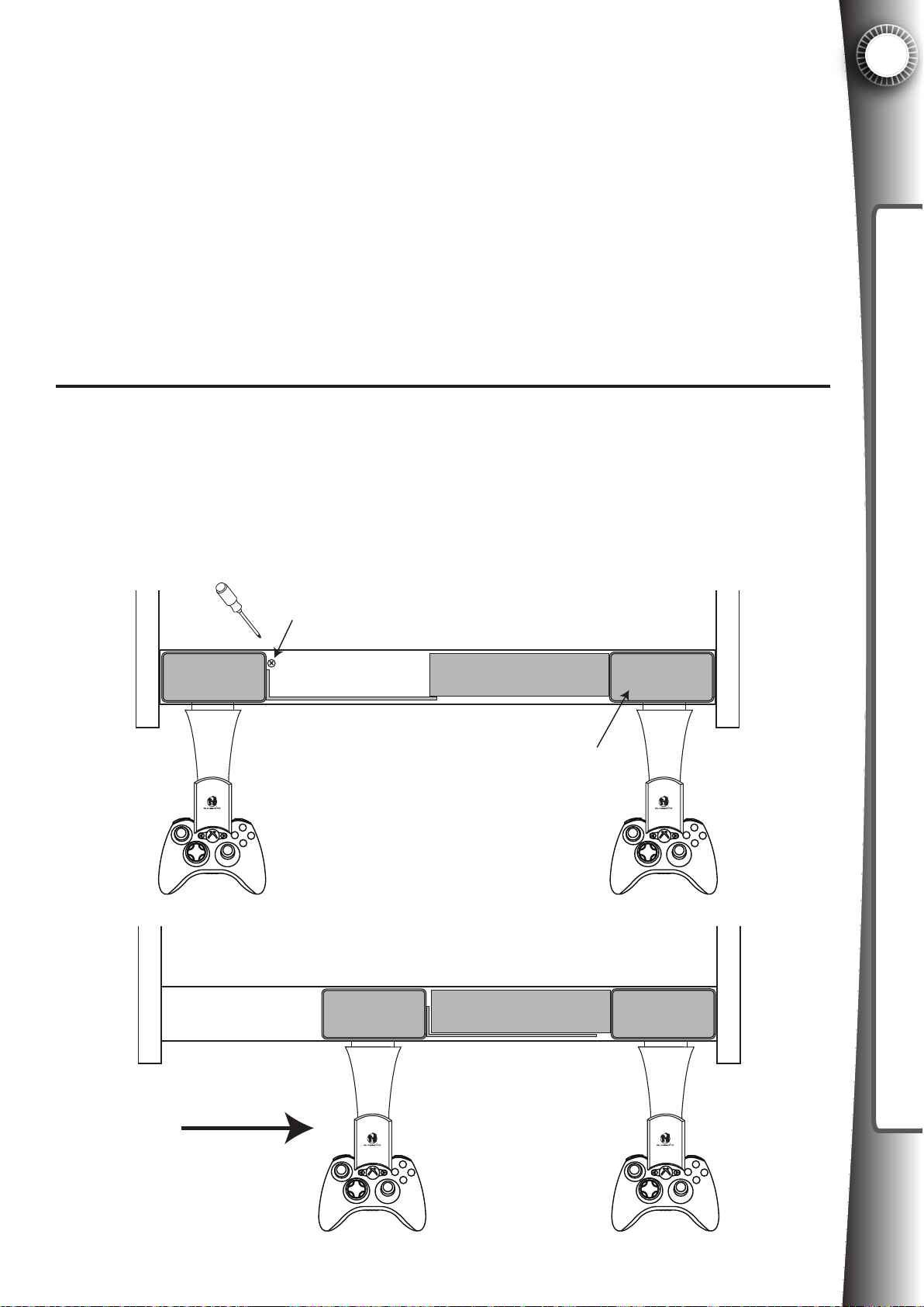
3.4 Sliding Controller Bracket
In the case where a single player game is started, it is more ergonomic for the player to use
the controller in the center of the machine. This is an optional feature that you may wish to
enable. Game Gate™ VU ships with the left player locked in position (the right player is not
adjustable). To release the left player and allow the controller to slide, simply open the control
panel and remove the set screw as shown in the diagram below.
3
SETUP INSTRUCTIONS
Remove screw to allow left player to slide
Right player is always
fixed in position
Center position is
more ergonomic for
a one player game
Fig. 3.4A
23
Page 32
3
Game Gate™ VU has several volume settings that are adjusted by the software, for example
the volume level in the attract mode versus the volume level during play mode (see Section
6.1). However, the settings in the software are only relative to the master volume level, which
is set using the dials on the volume control module, which is located behind the top coin door.
Open the top coin door to access the module (see Fig 2.7D). Adjust the volume to your pref-
SETUP INSTRUCTIONS
erence using the dials.
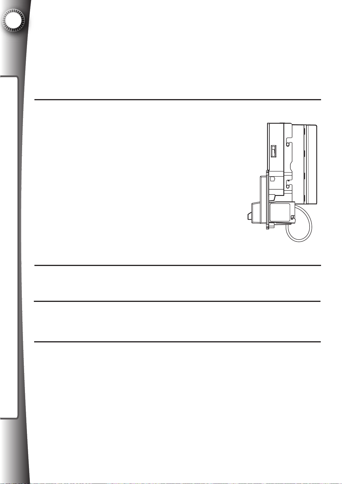
Quasimoto recommends MEI’s AE2600 upstacking bill validator. The
2400 series may also be used, but function may be limited for bills higher
than $5. Please check to make sure the acceptor can read the newer
style bills. For details please visit MEI’s website at www.meigroup.com
3.5 Setting Master Volume and Bass
3.6 Installing a Bill Acceptor
Fig 3.6A
Remove the metal blanking plate from the upper door. Use a wrench to remove the 4
1
nuts.
Insert the bill acceptor body into the opening. Reinstall the 4 nuts and tighten with
wrench
2
If the bill acceptor is a 110VAC version, and you are in 110VAC area, plug the BA into
3
an available outlet on the inside of the cabinet.
24
Page 33
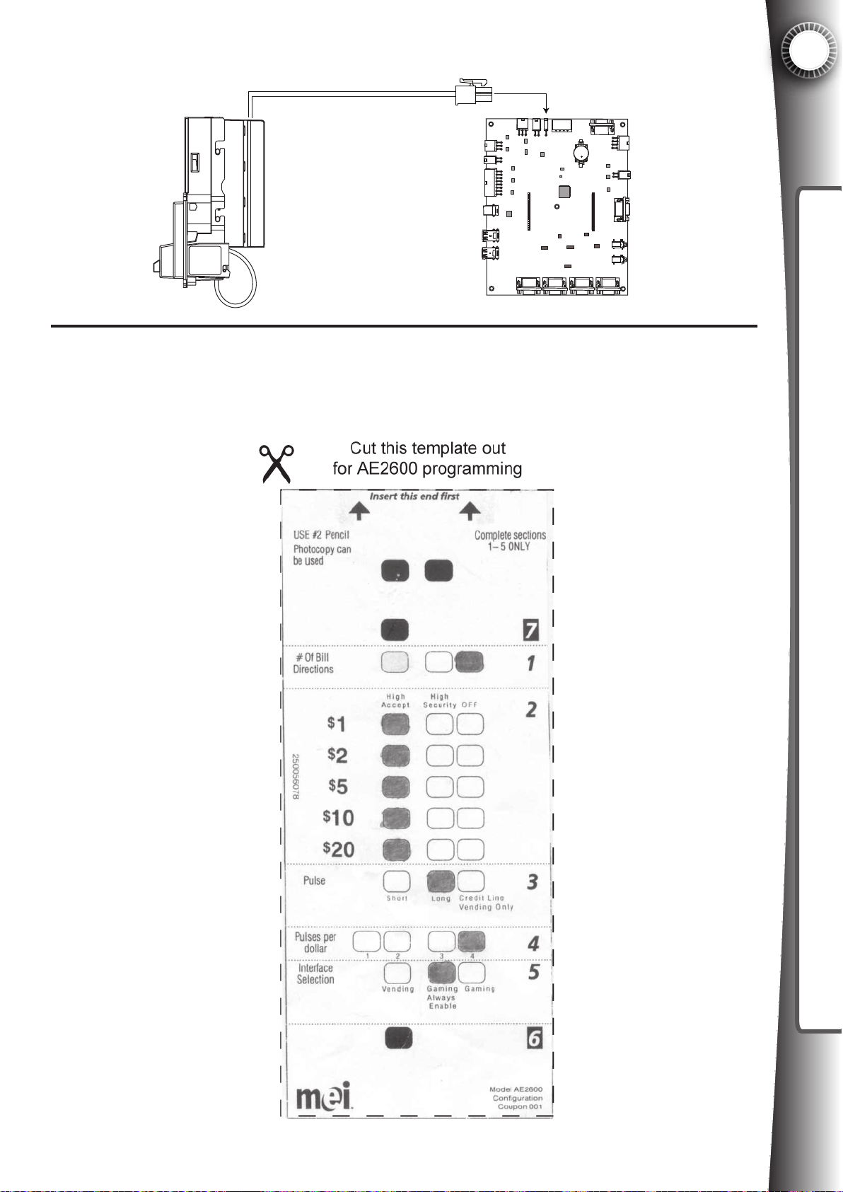
Connect the bill acceptor to the timerboard in the correct location as shown. (J16).
4
3
J10
J25
J3
J12
J9
J8
J10
P6 J7
J17 J16
P14 P5
J4
J13
J15
J27
J26
J19J20J21J22
Fig. 3.6B
Be sure that the bill acceptor is properly programmed. Follow the instructions included
with the bill acceptor, and insert the scan program document with the following informa-
5
tion (an additional copy of this information is located at the end of the manual,
which can be cut out and inserted):
SETUP INSTRUCTIONS
25
Page 34
4
4. INSTALLING A VIDEO GAME SYSTEM
The following section details 20 steps on how to install the Xbox 360® video game
system hardware into the Game Gate VU™ cabinet. In this section you will learn how to
INSTALLING A VIDEO GAME SYSTEM
install the external memory sockets, secure the Xbox 360® to the cabinet, connect the
audio and video, connect the power, and install the handheld controllers. If you intend to
install a PLAYSTAION®3 to the cabinet, please move to the next section “Installing a
PLAYSTATION®3.
There are several different versions of the Xbox 360® available at retail. Game Gate™
VU is compatible with all of the versions, which vary only slightly by the accessories
included with each. At the time of this manual, there are three versions available:
Arcade - includes the core system with no harddrive, 512mb of internal memory, a small
collection of games, and a wireless controller.
Pro - includes the core system with a small harddrive and is usually bundled with full
retail software version, as well as a wireless controller.
4.1 Installing The Xbox 360®
Elite - color is black instead of white, includes a large hard drive and is usually bundled
with full retail software, and a black wireless controller.
The “Arcade” version is the least expensive and is recommended by Quasimoto for use
with the Game Gate™ as the hard drive offers limited benefits to Game Gate™ VU
operators.
Since each console only includes one controller, you must purchase the second controller. DO NOT buy off-brand (third-party) controllers as they will not fit the controller
brackets included with the Game Gate™ VU. Only purchase Microsoft brand (first
party) controllers.
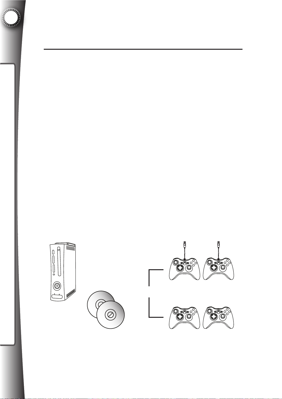
To install the Xbox 360® you will need the following components
available at your local electronics retailer:
Retail Xbox 360®
Video Game System
Xbox 360®
OR
Wired Controllers
26
Retail Xbox 360®
Video Game Disk
Xbox 360®
Wireless Controllers
Page 35
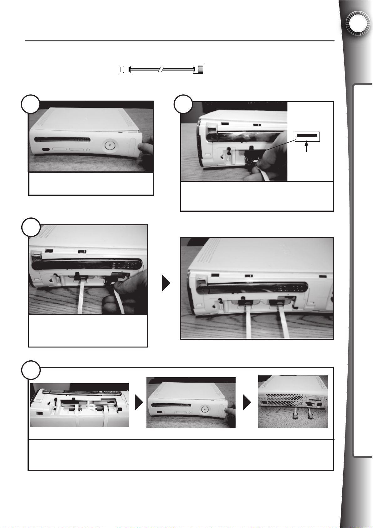
4.1A Xbox 360®: Memory Socket Connection
4
Parts needed:
1
Remove the Xbox 360® faceplate
3
Xbox 360® Memory Socket Cable x 2
PART#2095031
INSTALLING A VIDEO GAME SYSTEM
2
Push PCB under
Insert the Xbox 360® Memory Socket Cable into
the left memory unit port. Electrical contacts
face up as shown.
Repeat Step 2 for right side memory
unit port using the second Xbox 360®
Memory Socket Cable.
4
Wrap the ribbon cable under the Xbox 360® console and replace the faceplate. Note that ribbon
cables now appear hidden from the front view of the system. The connectors at the end of the
ribbon cable will be used once the Xbox 360® is placed in the cabinet.
27
Page 36
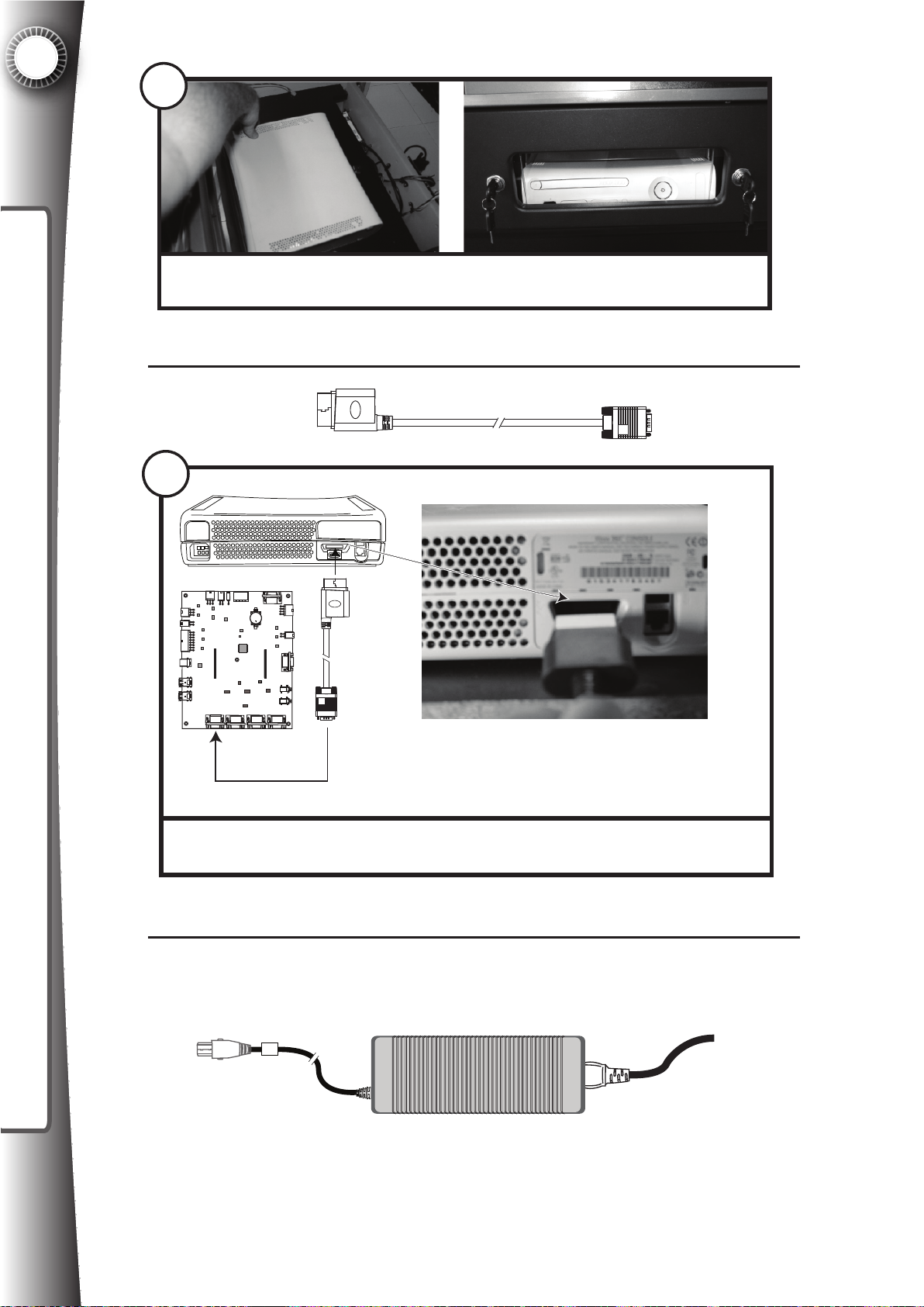
4
5
INSTALLING A VIDEO GAME SYSTEM
Remove the control panel and pplace the Xbox 360® in the cabinet as shown, with
the front of the system visible through the acrylic window.
4.1B Xbox 360®: Audio & Video Connection
Part needed:
Xbox 360 AV Cable x 1
6
J10
J25
J3
J12
J9
J8
J10
Connect the Xbox 360® AV Cable to the back of the Xbox 360® as shown. This
cable is factory connected to the far left port of the timerboard.
P6 J7
J17 J16
P14
J21J22
J4
J13
J15
P5
J27
J26
J19
J20
(factory connected)
PART#2095011
Part needed:
28
4.1C Xbox 360®: Power Connection
Xbox 360® Power Supply
(included with Xbox 360® video game console)
Page 37
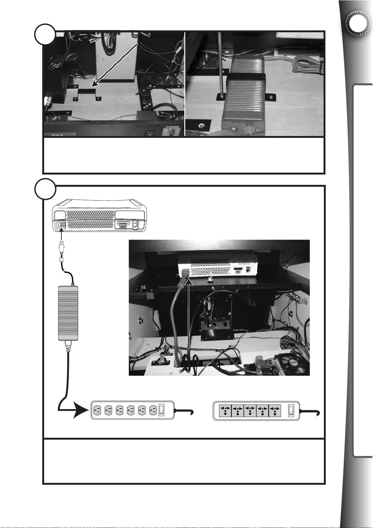
7
Locate the metal bracket at the bottom of the cabinet. Use a screw driver to
loosen the two screws and slide the power supply into the bracket. Tighten to
secure the power supply to the base of the cabinet.
8
4
INSTALLING A VIDEO GAME SYSTEM
OR
Flip the hinged panel down and feed the power cord up to the back of the game
system as shown. Connect the Xbox 360® power supply to the Xbox 360®
power port and the other end to an available outlet inside the Game Gate™ VU
cabinet. The power strip will vary depending on the voltage for your area.
29
Page 38
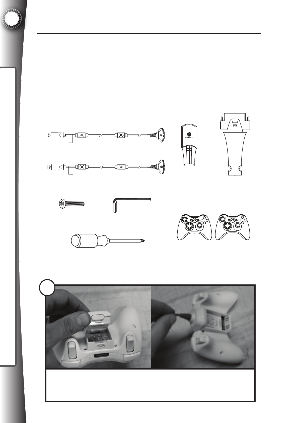
4
9
Remove the battery pack from the wireless controller. Connect the Wireless
Controller Cable into the back port on the wireless controller. Note that the
cables are different lengths, the controller intended for the left player (player 1) is
longer.
4.1D Xbox 360®: Installing The Handheld Controllers
There are two types of controllers for the Xbox 360®: wired and wireless. The Xbox 360
video game system includes one wireless controller. The wired controllers are a little less
expensive than the wireless, so we have included brackets for both types. In the case of
using the wireless controller, batteries will not be required. Refer to the respective
instructions below based on the type of controller to be installed. It is possible to have
one player with a wireless controller and the other player with a wired controller.
Parts needed:
4.1D1 Wireless Controller Installation
PLAYER 1
(LEFT)
PLAYER 2
(RIGHT)
Xbox 360®
Wireless Controller
Bracket x 2
PART#2091021
Controller Arm
Assembly x 2
PART#2092101
Xbox 360® Wireless Controller Cable 1P x 1
PART#2095001
Xbox 360® Wireless Controller Cable 2P x 1
PART#2095002
Security Screw x 8
Security Screw Driver x 1
Xbox 360®
Wireless Controllers (1 or 2)
Phillips Screw Driver
INSTALLING A VIDEO GAME SYSTEM
30
Page 39
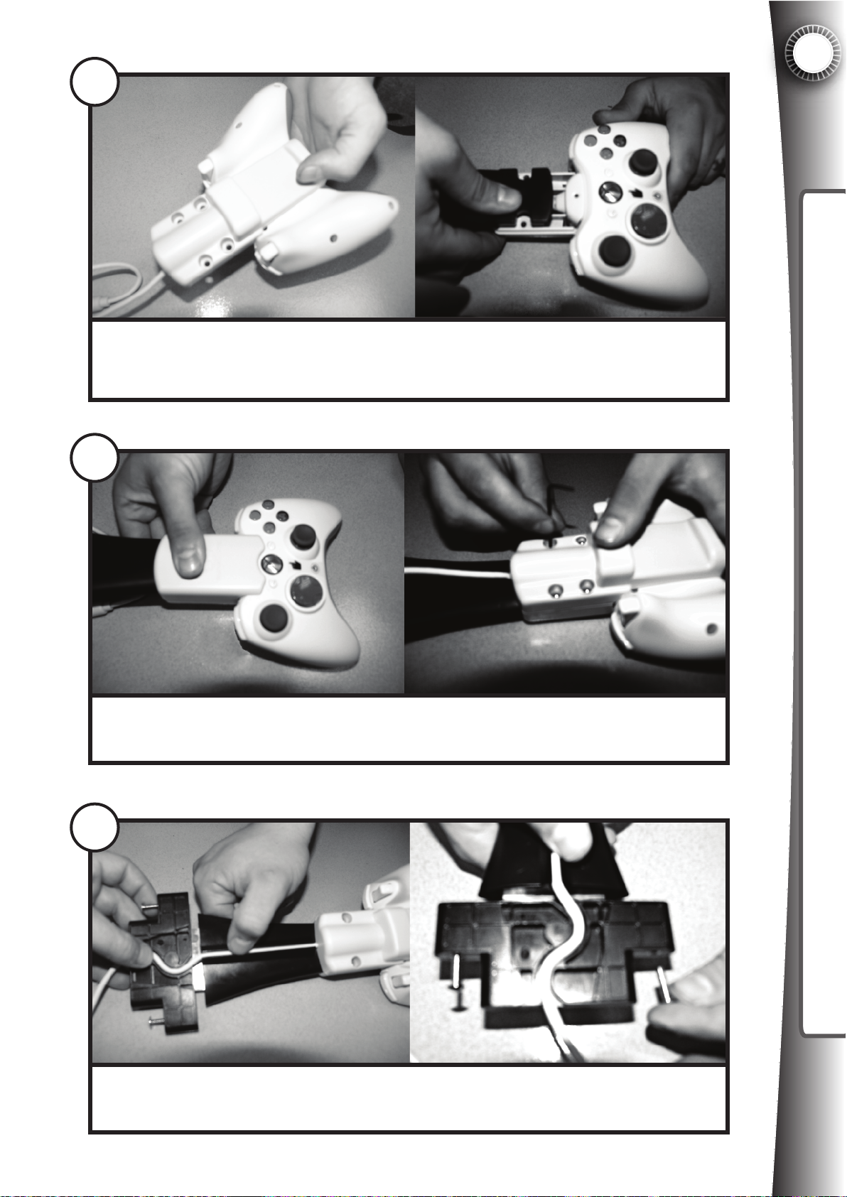
10
Place the bottom of the Wireless Controller Bracket over the batter cover as
shown. Press the Controller Arm Assembly into the bottom of the bracket feeding the cable out the back.
11
4
INSTALLING A VIDEO GAME SYSTEM
Place the top of the Controller Bracket over the controller. Insert security screws
and tighten with the security screw driver.
12
Push the cable into the rubber channel and into the S-channel of the controller
arm assembly. Remove the two screws from the Controller Arm Assembly.
31
Page 40
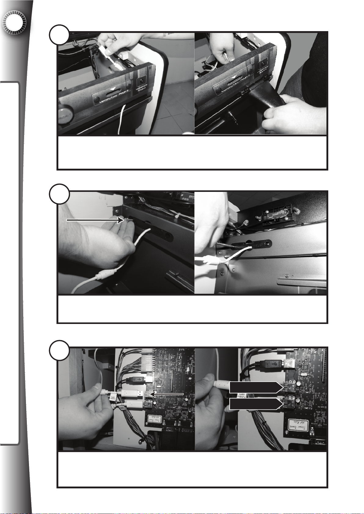
4
13
INSTALLING A VIDEO GAME SYSTEM
If using the Player 1 cable, feed the cable through the controller port on the left
as shown. Push the Controller Arm Assembly into the controller port.
14
Insert the screws into the back of the controller port and tighten with a screwdriver.
15
PLAYER 1
PLAYER 2
Connect the Player 1 cable into the Player 1 USB port on the timerboard. If you
have a second wireless controller, repeat this process for the right controller
port, and connect to the Player 2 USB port on the timerboard.
32
Page 41
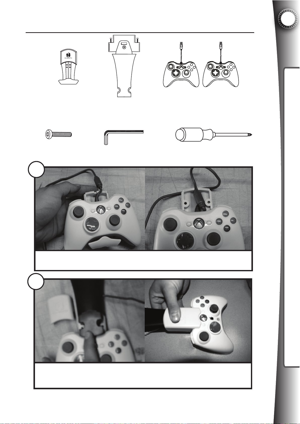
4.1D2 Wired Controller Installation
Parts needed:
4
INSTALLING A VIDEO GAME SYSTEM
Xbox 360®
Wired Controller
Bracket x 2
PART#2091011
Security Screw x 4
9
Controller Arm
Assembly x 2
PART#2092101
Security Screw Driver x 1
Xbox 360®
Wired Controllers (1 or 2)
Phillips Screw Driver
Snap the wired controller into the base of the wired controller bracket as shown.
Tuck the ferrite core into the controller bracket compartment.
10
Press the controller bracket arm into the controller bracket bottom, covering the
ferrite core as shown. Add the top of the controller bracket over the Xbox 360
controller.
33
Page 42
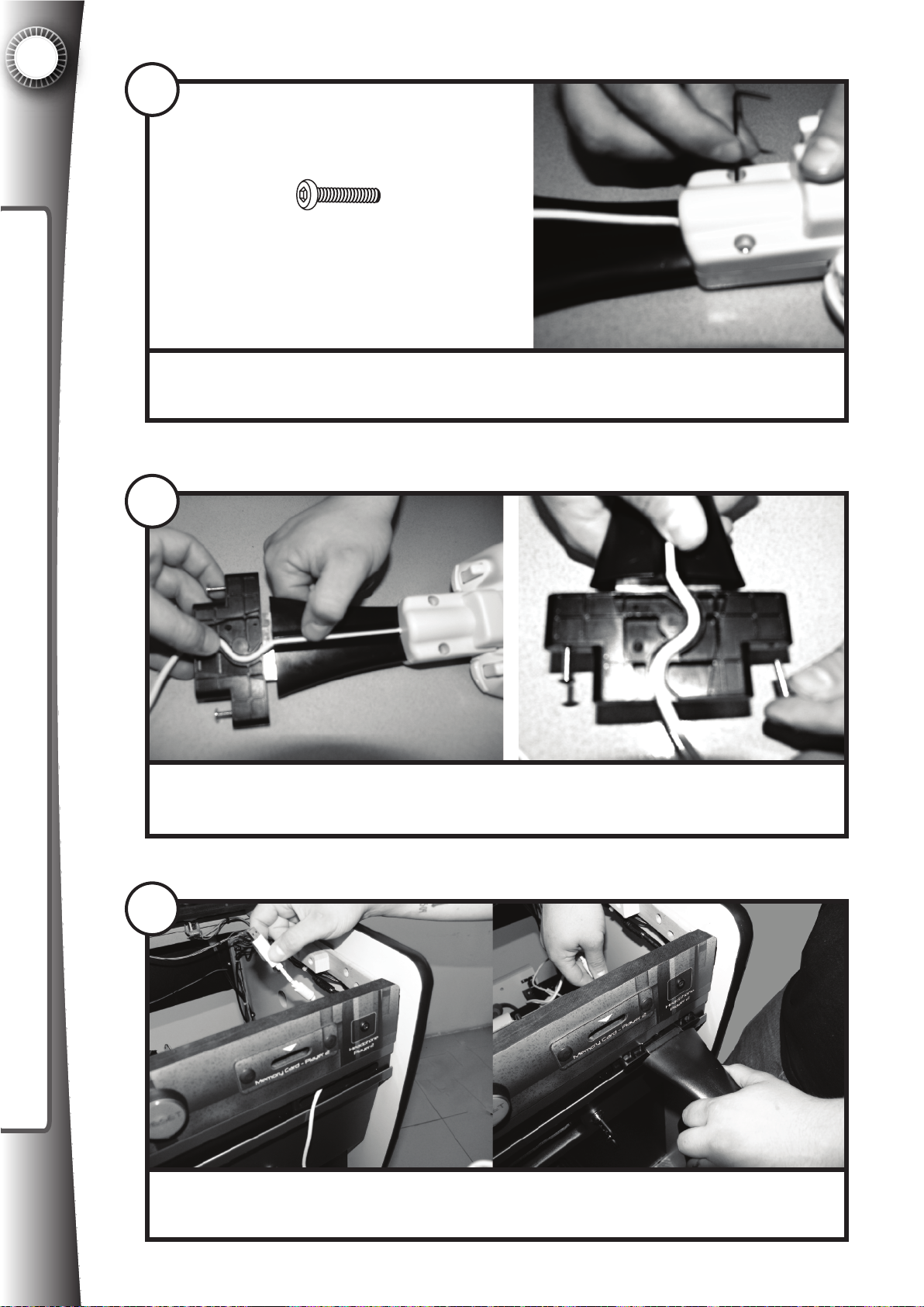
4
11
INSTALLING A VIDEO GAME SYSTEM
Security Screw x 2
Insert security screws into the Controller Bracket bottom and tighten with the
security screw driver.
12
Push the cable into the rubber channel and into the S-channel of the Controller
Arm Assembly. Remove the two screws from the Controller Arm Assembly.
13
Feed the cable through the controller port on front of the cabinet. Push the
Controller Arm Assembly into the controller port.
34
Page 43
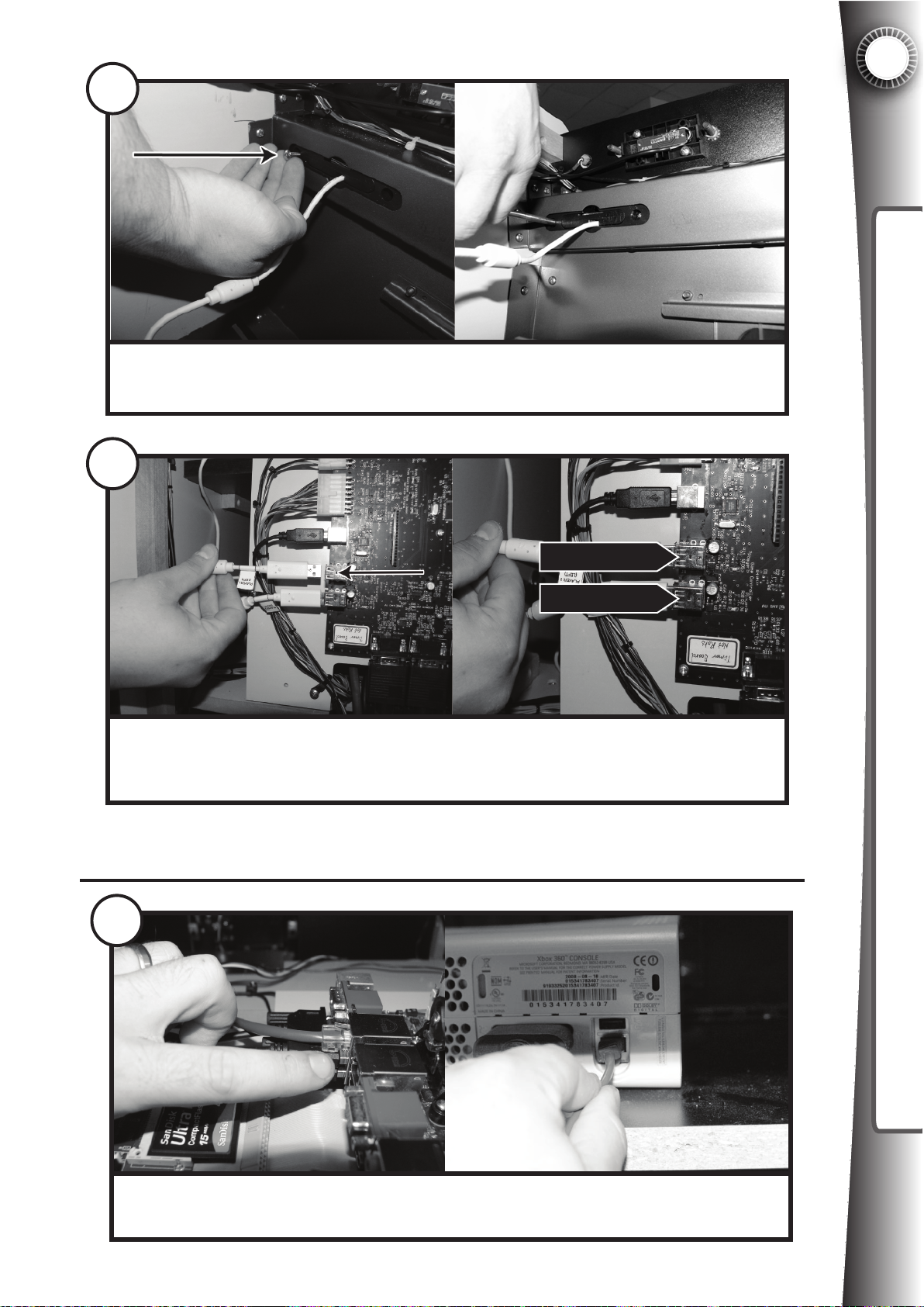
14
Insert the screws into the back of the controller port and tighten with a screwdriver.
15
4
INSTALLING A VIDEO GAME SYSTEM
PLAYER 1
PLAYER 2
Connect the Player 1 cable into the Player 1 USB port on the timerboard (J8). If
you have a second wired controller, repeat this process for the right controller
port, and connect to the Player 2 USB port on the timerboard (J10).
4.1E Xbox 360®: Network Connection
16
OPTIONAL: Locate the ethernet cable connected to the ATX board. Connect
this cable to the ethernet port on the back of the Xbox 360®.
35
Page 44
4
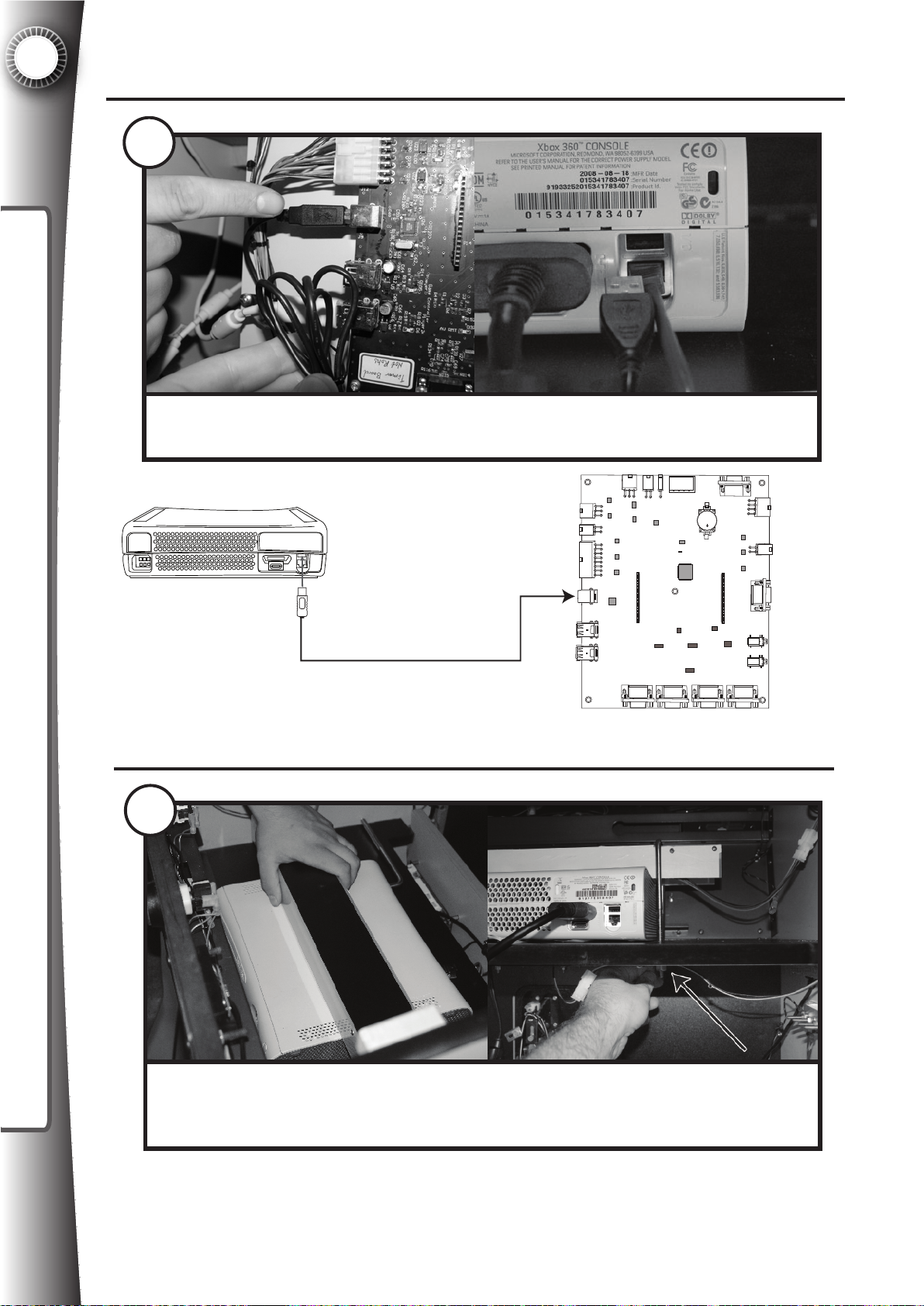
4.1F Xbox 360®: Connect The USB Port
17
INSTALLING A VIDEO GAME SYSTEM
Locate the USB cable connected to the timerboard (J9). Connect the end of this
cable to the rear USB port of the Xbox 360® as shown.
18
J10
J17
J25
J3
J12
J9
P14 P5
J8
J10
P6 J7
J16
J19J20J21J22
4.1G Xbox 360®: Securing The Xbox 360®
J4
J13
J15
J27
J26
Place the console light bar over the top of the Xbox 360®. Open the hinged
electronics shelf to gain access to the nuts under the shelf. Tighten the nuts on
the U-bolts to secure the Xbox 360® to the shelf. For extra security use a wrench.
Note: If your Xbox® has a hard drive attached (not required), you will need to use the
alternate U-bolt holes in the shelf. Simply remove the U-Bolts and reinstall into the outer
holes to accomodate the extra width created by the hard drive.
36
Page 45
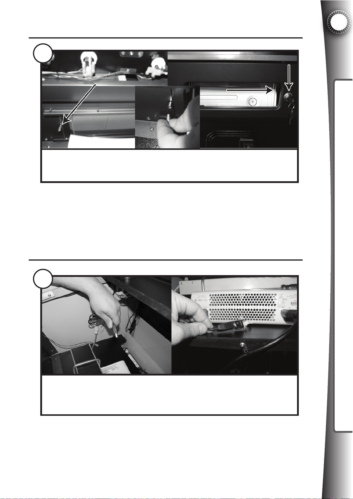
4.1H Xbox 360®: Sliding Acrylic Window
19
The acrylic door should slide to the right to gain access to the Xbox 360® DVD
drawer for changing of disks. Remove the lock restriction screw on the right so
that when the lock is opened it will allow this movement to occur.
Note: For the highest security, do not remove this screw. In this way if the lock is ever
picked by a criminal, it will still prevent the door from sliding. This will, however, make
changing the game more inconvenient. See the section titled “Security Overview” in this
manual for more information.
4
INSTALLING A VIDEO GAME SYSTEM
4.1I Xbox 360®: Memory Socket Connection
20
The final step for Xbox 360® hardware installation is to connect the two memory
port cables from step 4 to the memory jacks on the front of the Game Gate™ VU
cabinet. Locate the two USB plugs from the memory sockets and connect to the
ribbon cable jacks as shown.
See section “System Settings: Optimizing the Xbox 360®” for software details.
37
Page 46
4
4.2 Installing a PLAYSTATION®3
The following section details 20 steps on how to install the PLAYSTATION®3 video game
system hardware into the Game Gate™ VU cabinet. In this section you will learn how to
cover the Xbox® memory sockets (not used with PLAYSTATION®3), secure the
PLAYSTATION®3 to the cabinet, connect the audio and video, connect the power, and
install the handheld controllers. If you intend to install an Xbox 360® to the cabinet,
INSTALLING A VIDEO GAME SYSTEM
please go to the previous section “Installing an Xbox 360®.”
There have been several different versions of the PLAYSTATION®3 available at retail.
The differences being only the size of the harddrive and the backwards compatibility with
Playstation 2® titles. Game Gate™ VU is compatible with all PLAYSTATION®3 video
game consoles yet released to the market.
Note: PLAYSTATION®3 uses bluetooth wireless controllers for operation. Game Gate™
VU requires the activation and deactivation of controllers, which is not possible using a
standard PLAYSTATION®3 Dual Shock 3 game controller. Therefore it is required that
you obtain two PlayStation 2® game controllers for proper operation (more details
provided later in this section).
DO NOT buy off-brand (third-party) controllers as they will not fit the controller
brackets included with the Game Gate™ VU cabinet. Only purchase Sony® brand
(first party) controllers
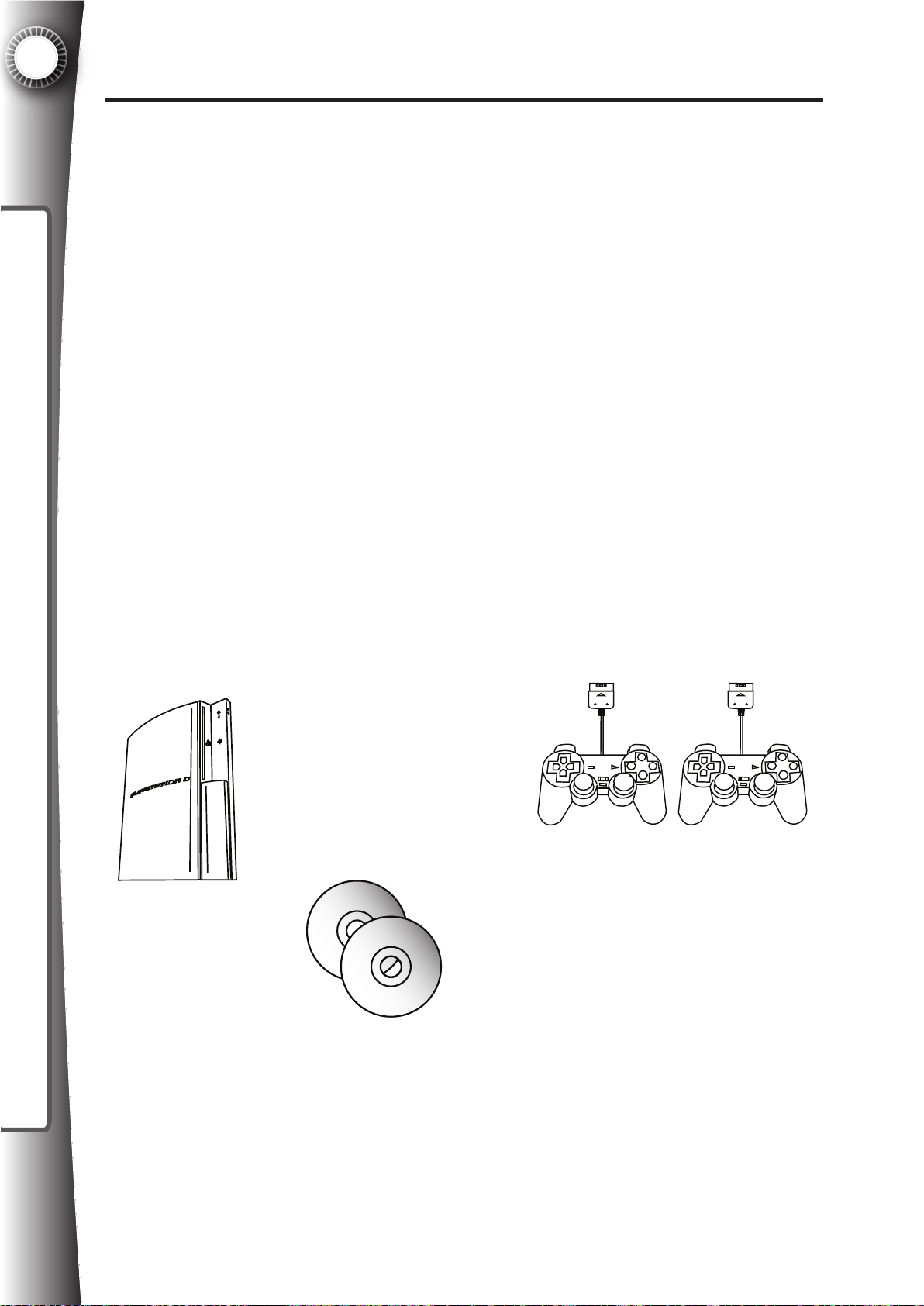
To install the PLAYSTATION®3 you will need the following components
available at your local electronics retailer:
Playstation®3
Video Game System
PlayStation 2®
Wired Controllers
(NOT Playstation®3 controllers)
38
Playstation®3
Video Game Disk
Page 47
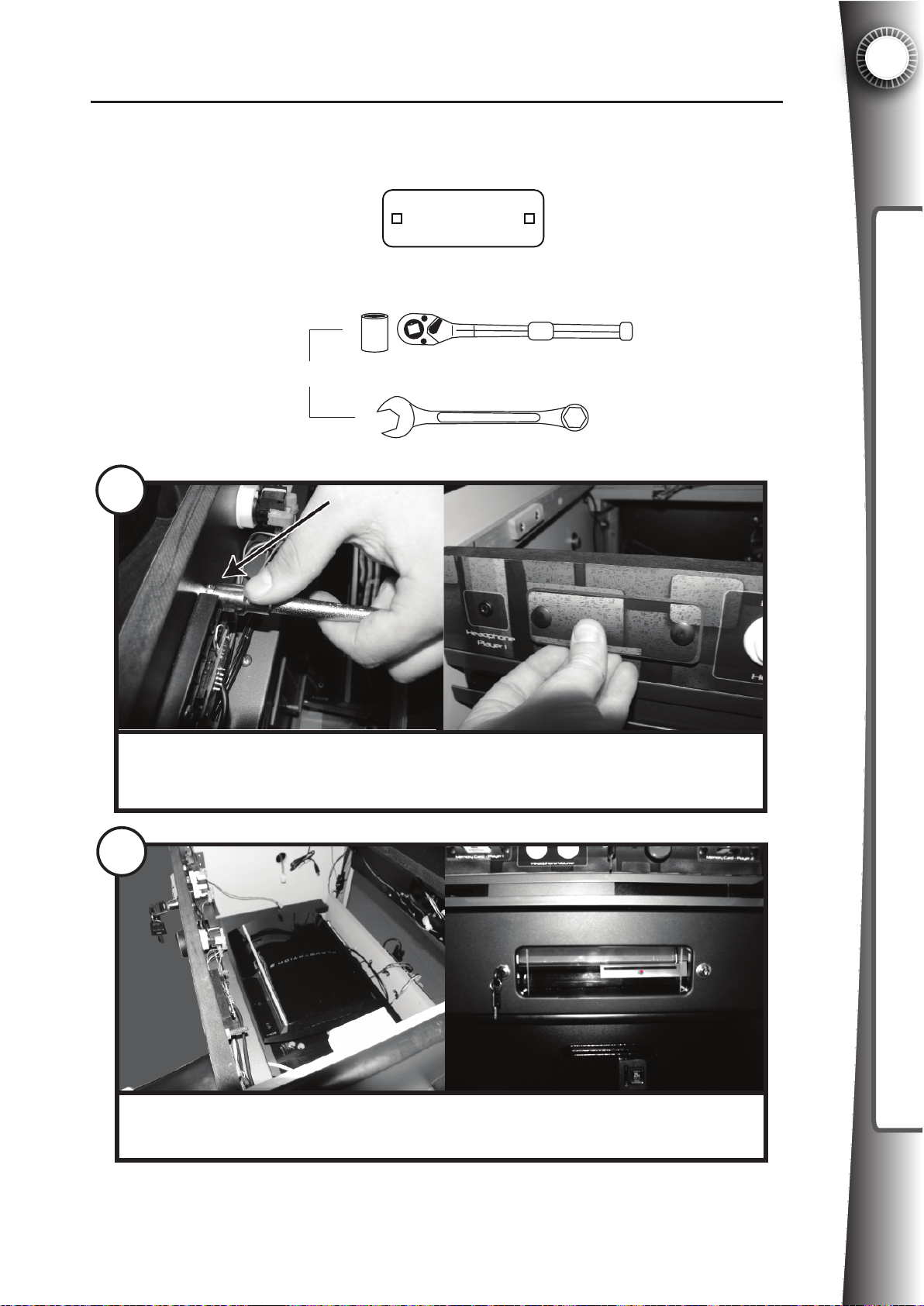
4.2A PLAYSTATION®3: Covering The Memory Sockets
The PlayStation®3 has a built in hard drive and does not have accessible memory sockets like the Xbox 360®. The Game Gate™ VU’s two memory sockets on the front of the
cabinet should be covered to prevent consumer confusion.
Parts needed:
PlayStation® Memory Cover x 2
PART#2093111
Tools needed:
M
E
C
I
T
R
OR
Socket Set
METRIC
Wrench
1
4
INSTALLING A VIDEO GAME SYSTEM
Remove the two bolts holding the original memory port cover by unscrewing the
two nuts on the backside of the panel. Replace with the PlayStation® Memory
Cover panel (graphic side out) and reinstall the bolts. Repeat for other side.
2
Place the PLAYSTATION®3 in the cabinet under the light bar as shown, with the
front of the system visible through the acrylic window.
39
Page 48
4
J3
J25
J10
J17 J16
P6 J7
J4
4.2B PLAYSTATION®3: AV Cable Connection
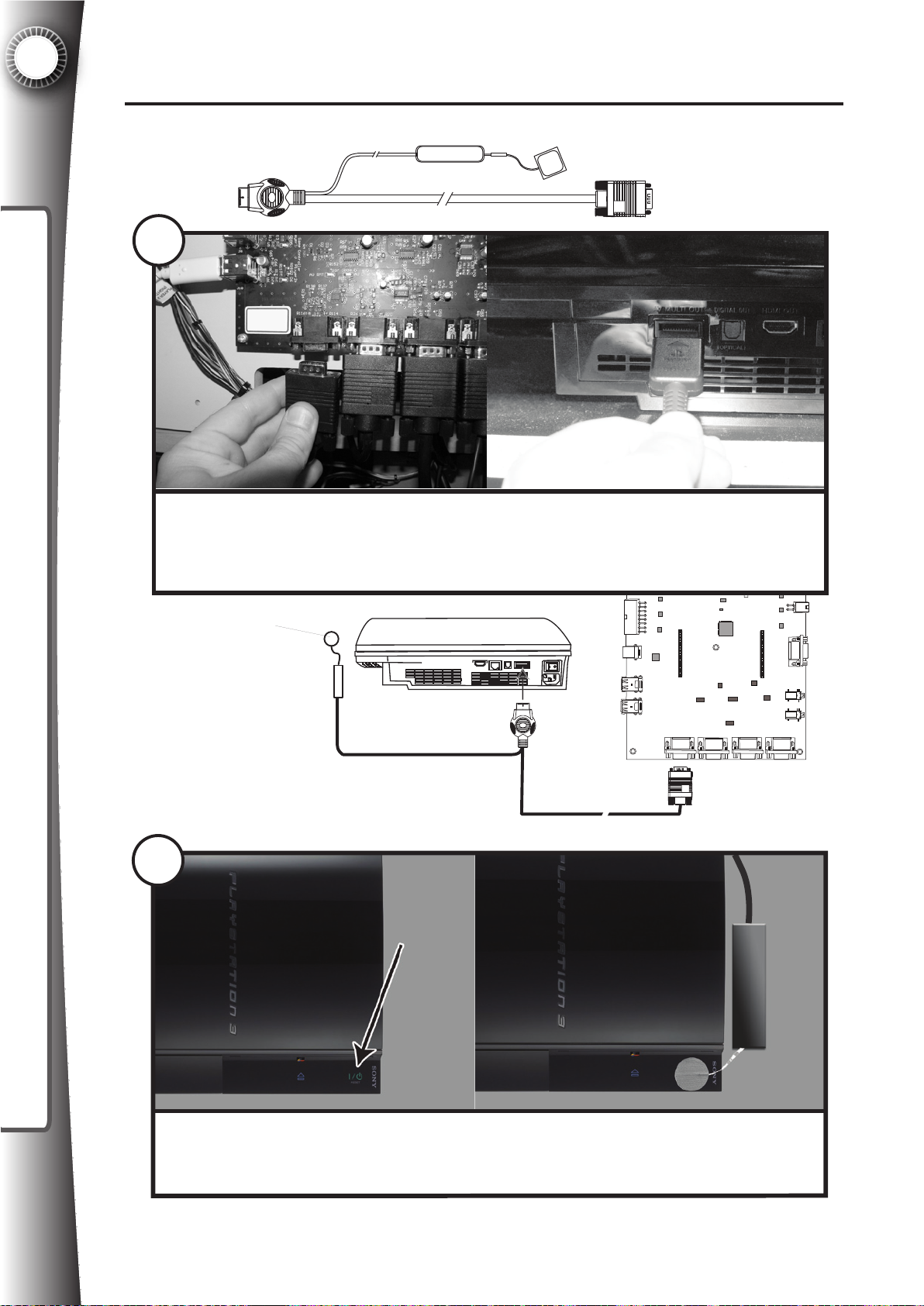
Part needed:
PlayStation® AV
Cable Assembly x 1
PART#2095021
INSTALLING A VIDEO GAME SYSTEM
3
Remove the factory installed XBOX360® AV cable from the timerboard by
unscrewing the terminal on the timerboard as shown. Replace this cable with
the PlayStation® AV Cable Assembly. Connect the cable into the AV port on the
game console.
Adhesive pad
J13
J12
J9
P14 P5
J8
J10
J15
J27
J26
J19J20J21J22
40
4
Peel off the strip from the adhesive pad. Stick the pad over the I/O button on the
front of the PlayStation®3. Place the cable to the right side of the PlayStation®3
so that it is out of the way.
Page 49
7
4
INSTALLING A VIDEO GAME SYSTEM
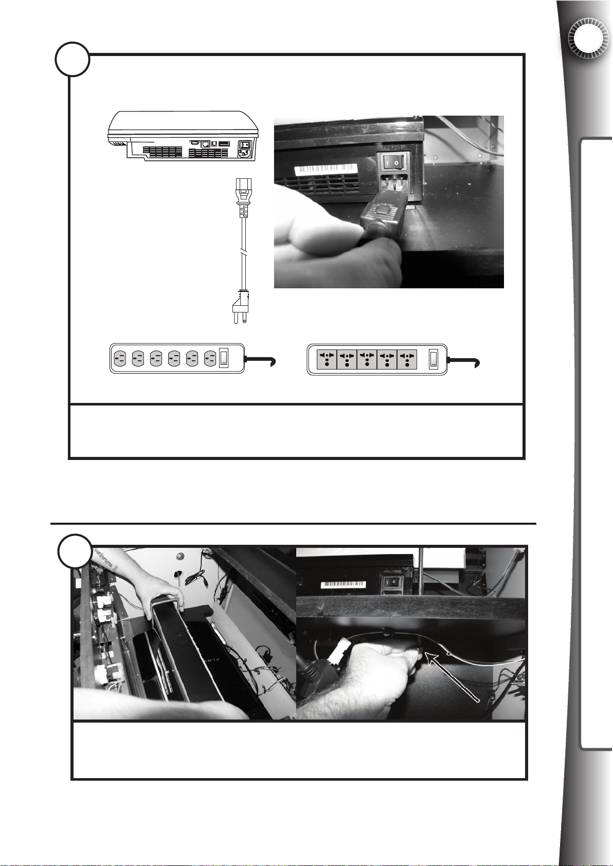
OR
Connect the power cord to the PLAYSTATION®3 power port and the other end
to an available outlet inside the Game Gate™ VU cabinet. The power strip will
vary depending on the voltage for your area.
4.2D PLAYSTATION®3: Securing The System
8
Place the console light bar over the top of the PLAYSTATION®3. Open the hinged
electronics shelf to gain access to the nuts under the shelf. Tighten the nuts on
the U-bolts to secure the system to the shelf. For extra security use a wrench.
41
Page 50
4
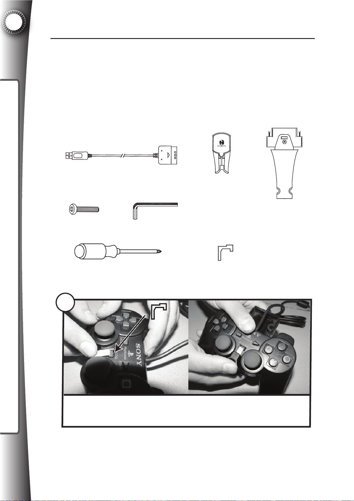
4.2E PLAYSTATION®3: Installing The Handheld Controller
The reason we have chosen to use Playstation 2® controllers instead of Playstation®3
controllers is that 1) Playstation 2® controllers are much less expensive to replace and 2)
we can prohibit users from changing Playstation®3 system settings by using a Playstation 2 controller. The function is identical in most cases between the two controllers. The
Playstation®3 controller can fit in the brackets with some adjustments, but because of the
INSTALLING A VIDEO GAME SYSTEM
wireless you will not be able to charge separate for 2 players and also you cannot protect
the system settings from tampering. The following details how to install the PS2 controllers.
Parts needed:
PlayStation® Controller Adapter x 2
PART#2097211
Security Screw x 4
Security Screw Driver x 1
PlayStation®
Wired Controller
Bracket x 2
PART#2091071
Controller Arm
Assembly x 2
PART#2092101
Phillips Screw Driver
Playstation Analog Bracket x 2
PART#2093161
9
Install the metal bracket so that the ANALOG button is pressed down. Snap the
wired controller into the base of the controller bracket as shown so that the metal
bracket is always pressing the ANALOG button.
42
Page 51
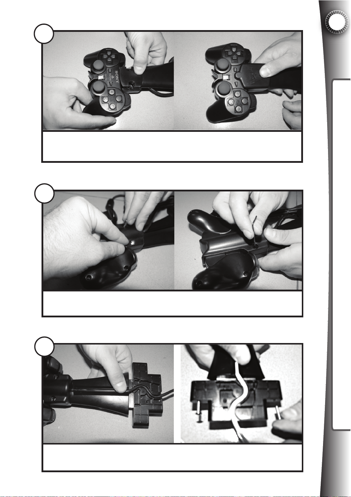
10
Press the Controller Bracket arm into the controller bracket bottom. Add the top
of the Controller Bracket over the PlayStation 2® controller.
4
INSTALLING A VIDEO GAME SYSTEM
11
Insert security screws into the Controller Bracket bottom and tighten with the
security screw driver.
12
Push the cable into the rubber channel and into the S-channel of the Controller
Arm Assembly. Remove the two screws from the Controller Arm Assembly.
43
Page 52
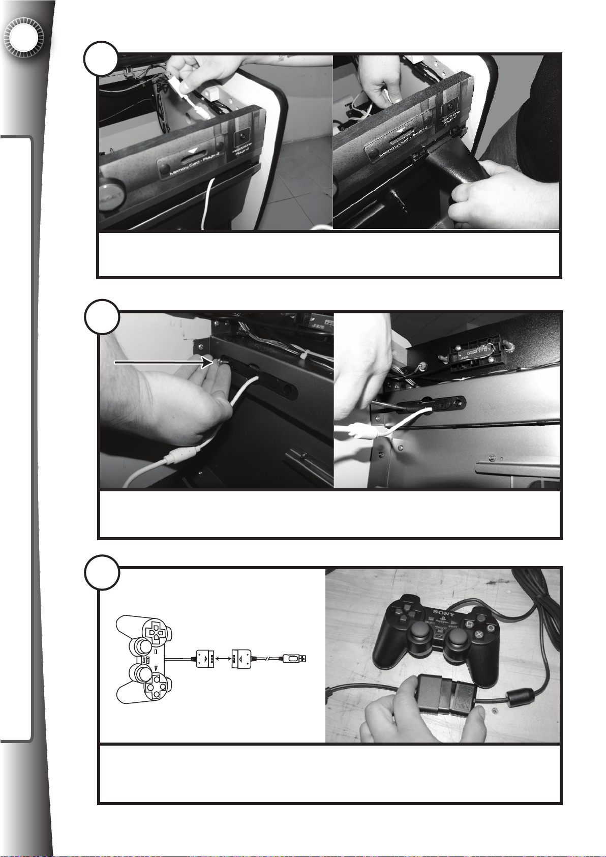
4
13
INSTALLING A VIDEO GAME SYSTEM
Feed the cable through the controller port on front of the cabinet. Push the
Controller Arm Assembly into the controller port.
14
Insert the screws into the back of the controller port and tighten with a screwdriver.
15
Connect the Playstation 2® cable end into the PlayStation® Controller Adapter
as shown. This converts the controller to a USB style plug so that it can be
connected to the timerboard.
44
Page 53
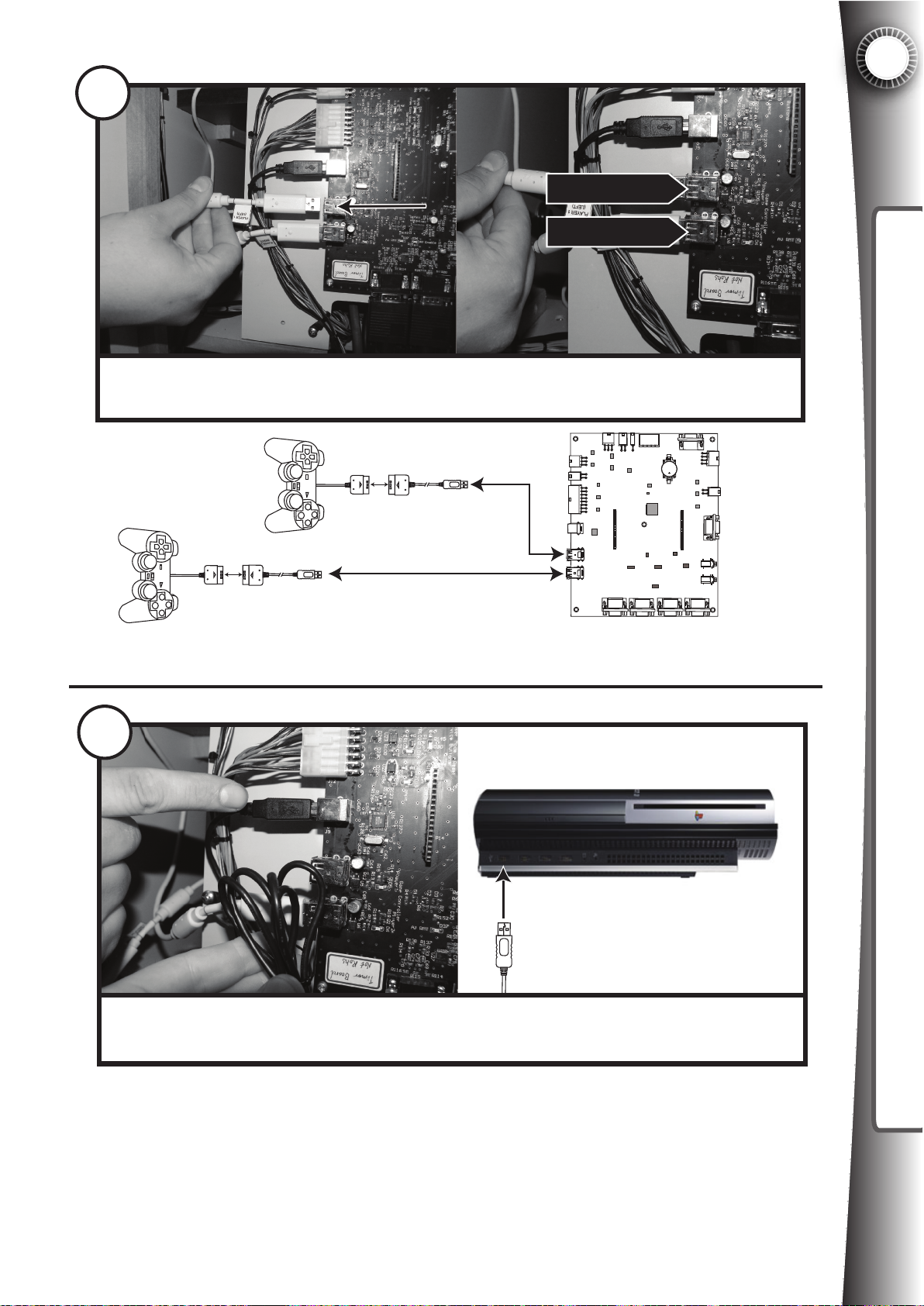
16
4
PLAYER 1
PLAYER 2
Connect the Player 1 cable into the Player 1 USB port on the timerboard (J8).
Connect the Player 2 cable to the Player 2 USB port on the timerboard (J10).
2P
1P
J10
J25
J3
J12
J9
J8
J10
P6 J7
J17 J16
P14 P5
J20
J21J22
J4
J13
J15
J27
J26
J19
4.2F PLAYSTATION®3: Connect The USB Port
INSTALLING A VIDEO GAME SYSTEM
17
Locate the USB cable connected to the timerboard (J9). Connect the end of this
cable to any USB port on the front of the PLAYSTATION®3.
45
Page 54
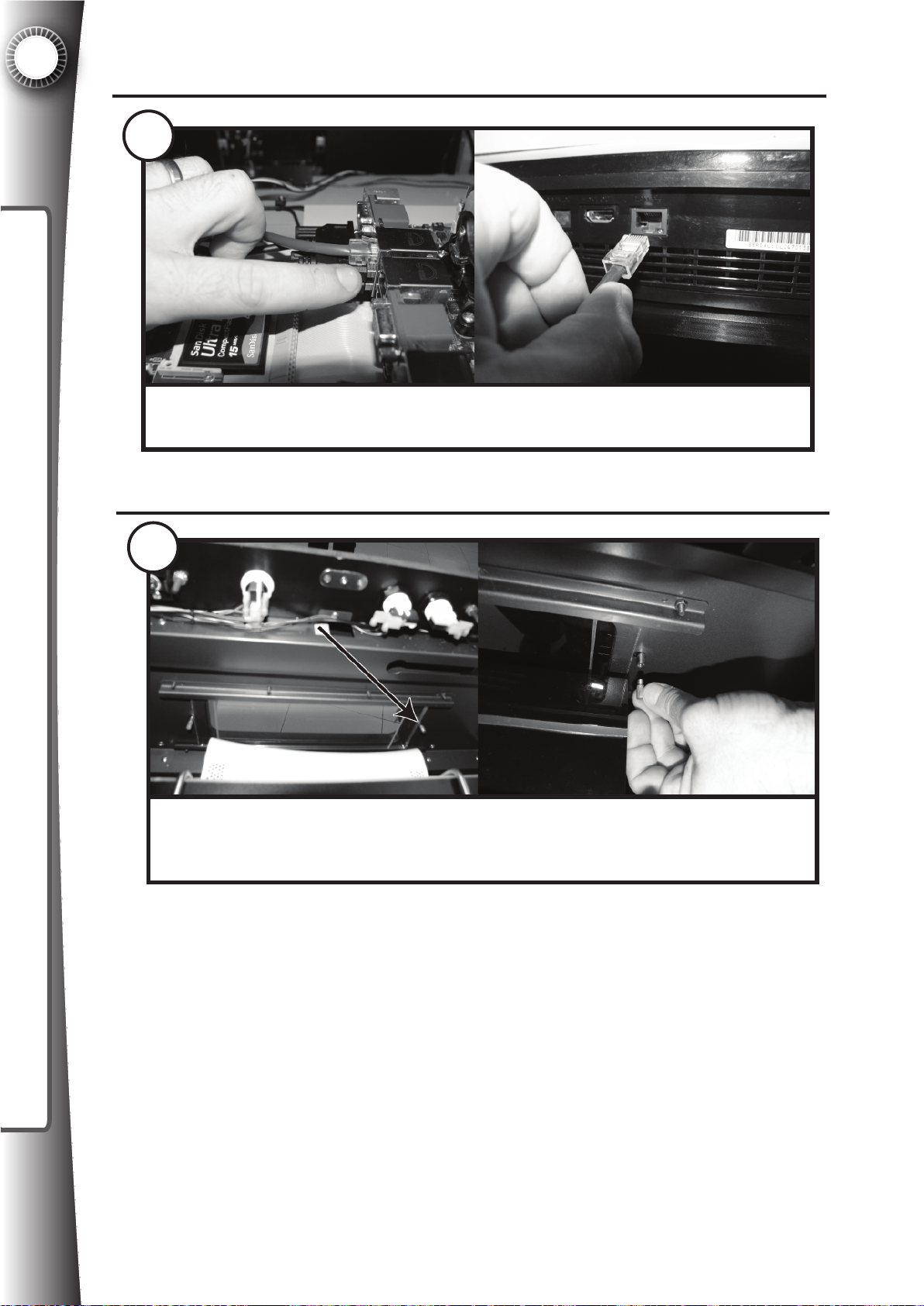
4
4.2G PLAYSTATION®3: Network Connection
18
INSTALLING A VIDEO GAME SYSTEM
OPTIONAL: Locate the ethernet cable connected to the ATX board. Connect
this cable to the ethernet port on the back of the PLAYSTATION®3.
4.1H PLAYSTATION®3: Acrylic Window
19
The acrylic door should slide to the right to gain access to the PLAYSTATION®3
DVD drawer for changing of disks. Remove the lock restriction screw on the
right so that when the lock is opened it will allow this movement to occur.
Note: For the highest security, do not remove this screw. In this way if the lock is ever
picked by a criminal, it will still prevent the door from sliding. This will, however, make
changing the game more inconvenient. See the section in this manual titled “Security
Overview” for more information.
46
Page 55
5. ACTIVATION & RENEWAL
5.1 Activation Overview
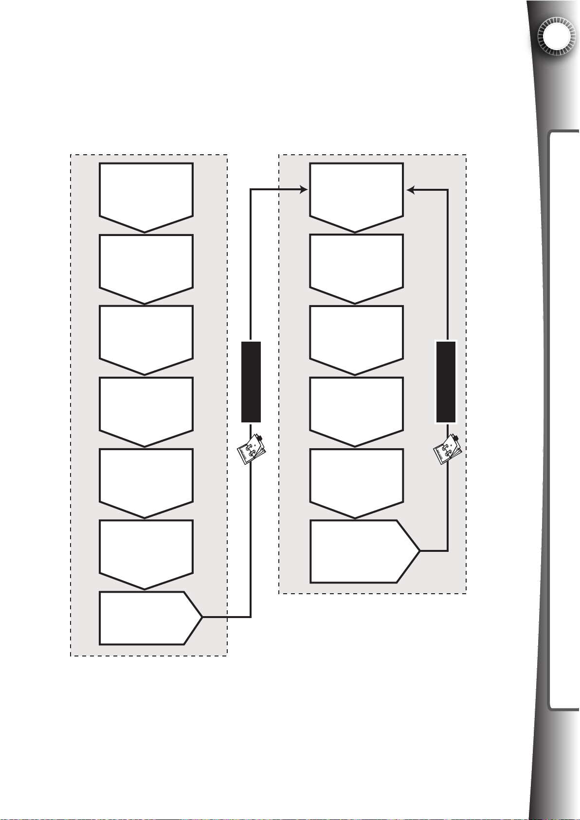
Game Gate™ VU ships deactivated and unregistered. You must register and activate Game
Gate™ VU. You must become a licensed member in order to activate the equipment. Mul-
tiple machines can be activated at one time if desired using a single USB ash drive.
5
FIRST TIME ACTIVATION PROCESS LICENSE RENEWAL PROCESS
FILL OUT
LICENSE
PAPERWORK.
GET LOGIN
AND PASSWORD
ASSIGNED.
GET FILE FROM
GAME GATE ONTO
USB FLASH DRIVE.
LOGIN TO
REGISTRATION
SERVER USING A PC.
6 MONTHS LATER
RECEIVE INVOICE
FROM LICENSE
MANAGER*
PAY INVOICE,
CREDITS ARE
ADDED TO SYSTEM
SAVE NEW LICENSE
REQUEST FILE
FROM EQUIPMENT
ONTO USB DRIVE.**
LOGIN TO ACCOUNT.
APPLY CREDITS.
GET NEW FILE.
ACTIVATION & RENEWAL
6 MONTHS LATER
REGISTER MACHINE
ON SERVER,
CLICK “ACTIVATE”.
GET NEW FILE
FROM SERVER.
SAVE TO USB
FLASH DRIVE.
LOAD NEW
FILE INTO GAME
GATE TO ACTIVATE.
* Invoice will be received at least 30 days prior to
license expiration (month 5).
** The license renewal process can be automated
for Game Gate units connected to the internet.
Service not available in all areas.
DOWNLOAD AND
SAVE NEW FILE
TO USB DRIVE.
LOAD USB DRIVE
INTO GAME GAME.
LICENSE EXTENDS
6 MONTHS.
Process Steps Summary
1. Fill out the license paperwork (provided by your distributor) and send the completed documents to the license manager (see your license paperwork for mailing details). This only
needs to be done once and is not required for future purchases after you have setup your account.
47
Page 56
5
2. You will receive a login and password from the license manager to access the Game Gate
registration server (http://www.gamegatecontrol.com). Your login and password will be sent to
you by mail and email.
3. Plug in your new Game Gate VU to a power outlet and follow the prompts, which will save
an important le to the included USB ash drive (called “control.gamegate”).
ACTIVATION & RENEWAL
4. Use a PC to login to your account. Register and activate the new machine by uploading
the le “control.gamegate” from the USB ash drive into the registration server (see section
5.2 for more details, you must browse for this le on your PC).
5. The registration server will modify the uploaded le “control.gamegate” and ask you to
save it back to your computer.
6. Save the new “control.gamegate” le to your computer and copy the le to the USB ash
drive, overwriting the previous version of the le.
7. Take the newer le, which is now on the USB ash drive and insert it into the USB port on
the Game Gate VU you want to activate. Follow the steps detailed in 5.2 below to nish the
activation, which is valid for 6 months of operation. Note, this process will also update the
Game Gate rmware if a new version is available. Attract videos should also be uploaded.
8. Thirty days prior to expiration you will receive an invoice for another 6 months of license.
Pay the invoice and credits will be added to the registration server. Follow steps detailed in
5.3 to apply the credits and extend the license so that operation will continue. This process
will repeat every 6 months for the life of the product.
5.2 First Time Activation Details
As mentioned in section 5.1 above, if this is the rst time you are powering the Game Gate
VU you must activate the equipment. Prior to activation the system will default to Free Play
Mode and Standard Play Mode (able to charge for play) will be disabled. The unit can also be
changed to Tradeshow Mode prior to activation (see Section 6).
Please follow these steps carefully.
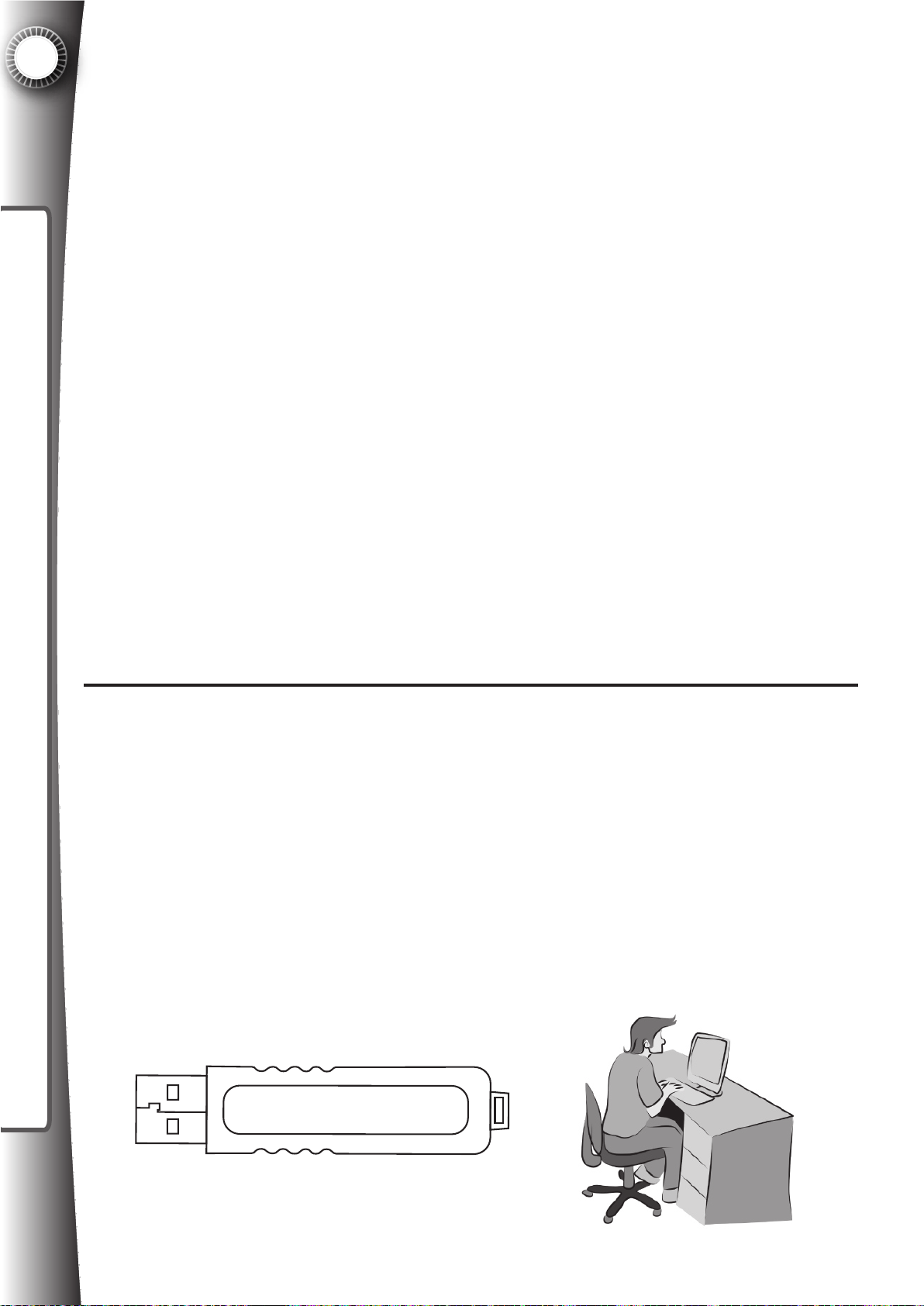
You will need: USB ash drive and a computer with internet access
2GB
48
USB Flash Drive x 1
PART#2097391
Page 57
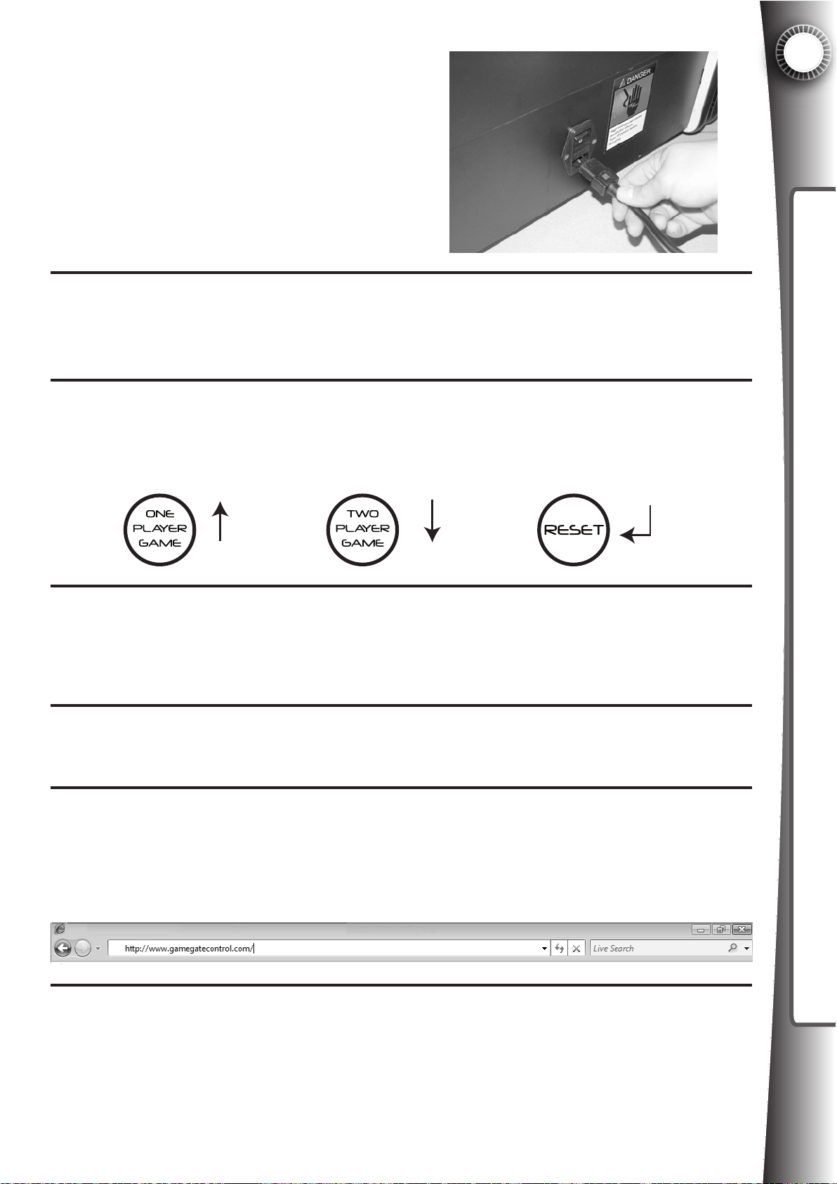
Plug the power cord in the back of the cabinet
and connect to a wall outlet.
1
Press the power switch. The unit will begin loading. You must follow the on-screen
2
prompts if this is your rst time to power on the machine. The equipment will not function until it has been registered.
You will be prompted to set the current date. This is an important step so please make
3
sure it is today’s date. Use the “One Player Game” button to make the number go up.
Press “Reset” to conrm the value. Go through each number and the next screen will
prompt to conrm the setting with the 1P button, or change with the 2P button.
5
ACTIVATION & RENEWAL
UP
Set the time in 24 hour military time (not am/pm; for example 3:00PM should be 15:00).
Again, use the “One Player Game” button to make the number go up and “Reset” to
4
conrm the value. Go through each number and the next screen will prompt to conrm
the setting with the 1P button, or change with the 2P button.
Screen will prompt you to insert the USB ash drive into the USB port behind the coin
5
door. Wait for processing and follow the prompt to remove the USB ash drive.
Take the USB drive to a computer with internet access. Insert the USB ash drive in an
6
available USB port on the computer. Start your browser (such as Internet Explorer) and
enter the following into the address bar: www.gamegatecontrol.com.
DOWN
ENTER
Enter the login and password given to you by the license manager. You must have
7
signed and submitted the license agreements to the license manager in order to receive
a login and password. If you are unsure about these steps, please contact your distributor for more information (See Section 9 for more details).
49
Page 58
5
ACTIVATION & RENEWAL
8
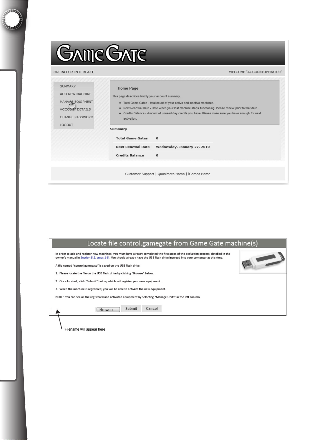
Once logged into the account, click “Add New Machines” to register the new equipment.
Follow the prompts.
You will be asked to locate a le named “control.gamegate”, which is located on the
USB ash drive you inserted into the computer in Step 6 above. Click “Browse” and
locate the USB drive in the folder window and locate the le. Click on the le. The le
name will appear in the text box. Click “SUBMIT”.
50
Page 59
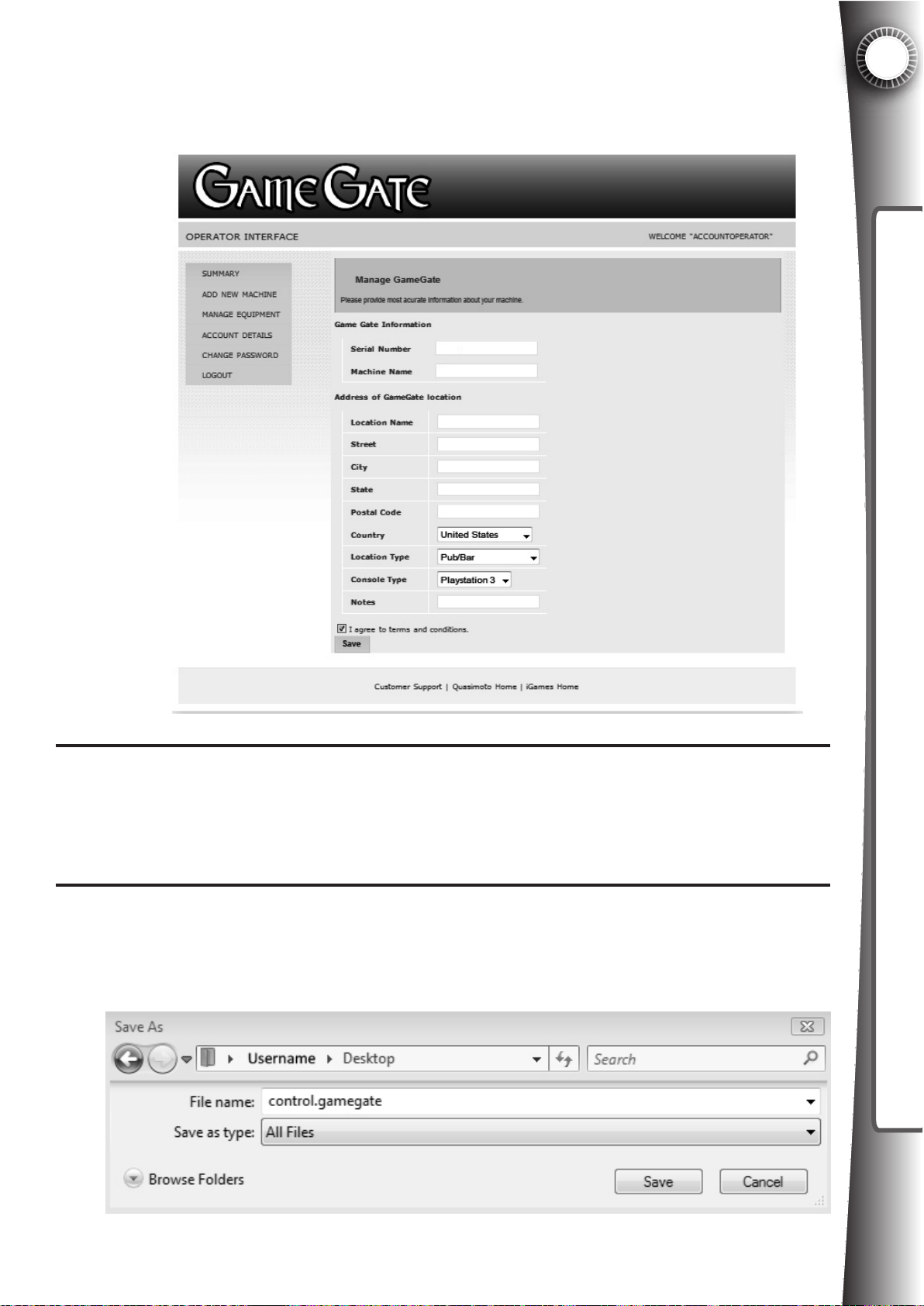
9
Enter the required information such as the location type and game used in the unit. You
can create a shorthand nickname for the unit (optional). Click the checkbox “I agree to
the terms and conditions” and click “Save”. Your new machine (or machines) will now
be registered waiting for activation.
5
ACTIVATION & RENEWAL
10
11
To activate the newly registered machine, click “Manage Units” in the left column. All
registered units will be shown. Check the box to the left of the unit or units you wish to
activate, and click “Activate”. This can be done for one or several machines at a time.
A window will appear (varies by browser you are using) asking you to save a le. Save
the le to a folder on your computer where you can nd it easily, such as the desktop
or the Download folder. NOTE: This le is also named “control.gamegate”, but it is a
newer version of the original le uploaded in Step 8.
51
Page 60
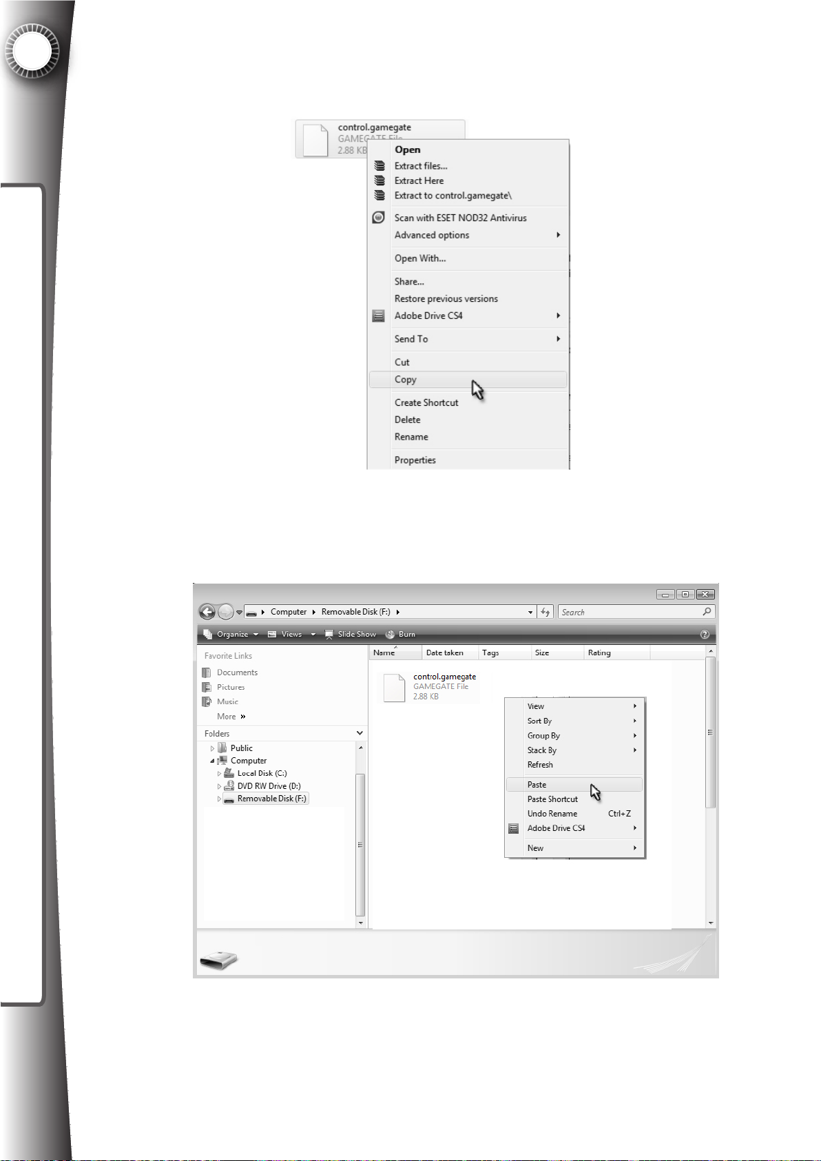
5
ACTIVATION & RENEWAL
12
Copy this le directly to the USB ash drive using standard copy and paste techniques.
For example, locate the new le on your computer, right click the le and choose
“Copy”.
Next browse for the USB ash drive and open the USB ash drive folder. Right click in
the window and choose “Paste”.
52
Page 61
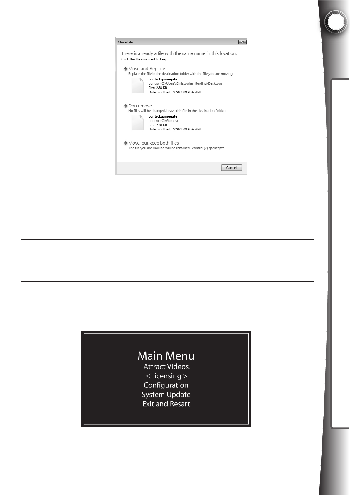
You will be asked if you want to overwrite the le.
You must overwrite the le so that the USB ash drive has the newer version of this
le, which includes the data necessary to complete the activation of your equipment.
In the example above choose “Copy and Replace” to overwrite the le. Your operating
system may show an alternate message, but the principle remains the same.
5
ACTIVATION & RENEWAL
13
14
Remove the USB ash drive from the computer. In the Explorer window, right click on
the drive and click “Safely Remove” to ensure proper removal.
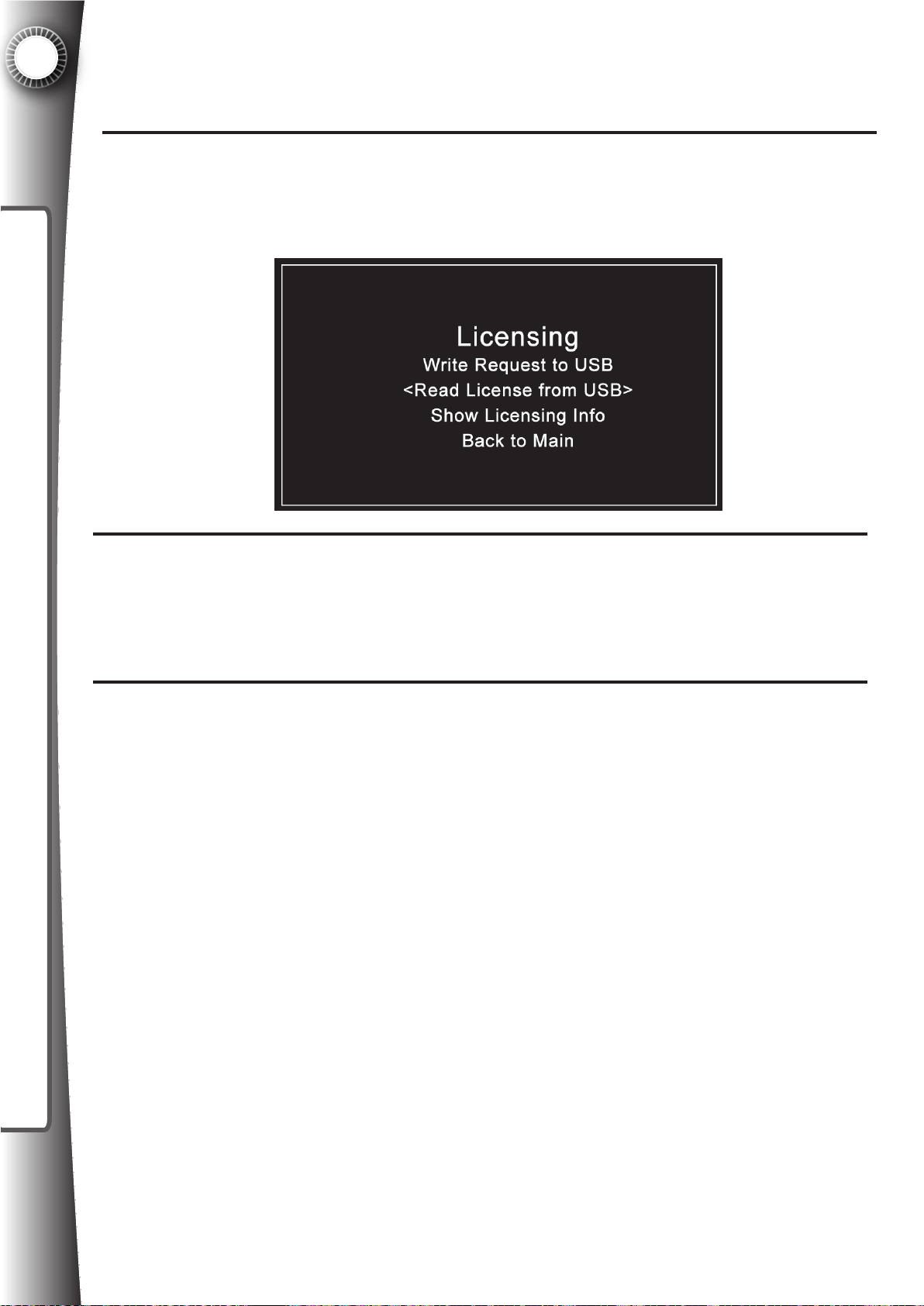
Take the USB ash drive to the Game Gate(s) you wish to activate. Power the machine and wait for the LED display to no longer say “Please Wait”. Insert the USB ash
drive into the USB port on the Game Gate. The following screen will appear.
53
Page 62
5
ACTIVATION & RENEWAL
15
16
Using the “One Player Game” button, cycle down to “Licensing” and press the “RESET” button to select.
Use the “One Player Game” button to scroll, and press “RESET” to select “Read
License from USB”. The new le from the registration server will be located and your
machine will activate.
Follow the onscreen prompt to remove the USB ash drive. A screen will appear dur-
17
ing the reboot sequence that will conrm the new license status (Active). The system
will be set to Standard Mode, and the Attract Mode will start after boot up and play
videos uploaded into the machine (see Section 6.4 to see how to upload videos).
5.3 License Renewal Process
Game Gate™ VU includes 6 months of activation and license, which must be renewed before
expiration. Failure to renew the license will result in equipment default to Free Play Mode
(locked). The process for renewal is straightforward.
There are two ways to renew the license. One is through the Internet if Game Gate™ VU
is connected to the network, the other is through a USB ash drive, similar to the activation
process.
You will be notied by mail and by email that expiration is eminent. The Game Gate™ VU will
also remind you of your expiration date. Also, the system is setup that if you own more than
one Game Gate™ VU and have purchased them at different times during the year, the expiration dates will synchronize, meaning there will only be two renewal dates to remember annually for all the Game Gate™ VU product you own.
Game Gate owners will receive an invoice ve months after initial activation. Game Gate
license fees are $8 per month, which is billed in 6 month periods or $48 per unit (dates are
tracked as “day credits”, or 182 day credits per 6 month activation).
54
Page 63
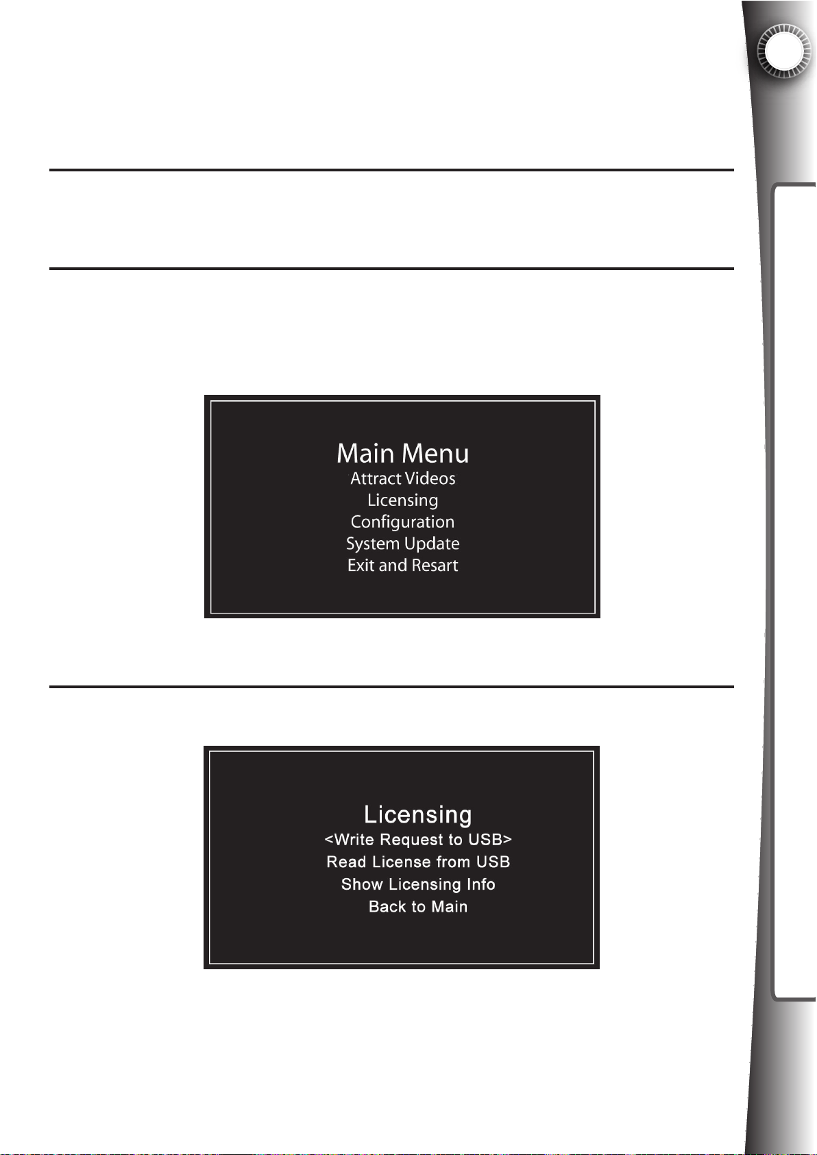
5.4 Machine Renewal Details - Extending the Activation
The instructions below assume that your Game Gate equipment is not connected to the inter-
net during the renewal process, in which case a USB ash drive will be required. The process
is similar to activation (see section 5.2 for images and more details).
5
Receive the invoice from the license manager for your Game Gate unit, in most cases it
is $48 per machine for 6 month extension (see section 5.3 above). Once payment has
1
been received, the license manager will add day credits to your account.
Power on the Game Gate and wait for “Please Wait” to end on the LED display. Insert a
USB ash drive (such as the one included with the machine) into the USB port located
2
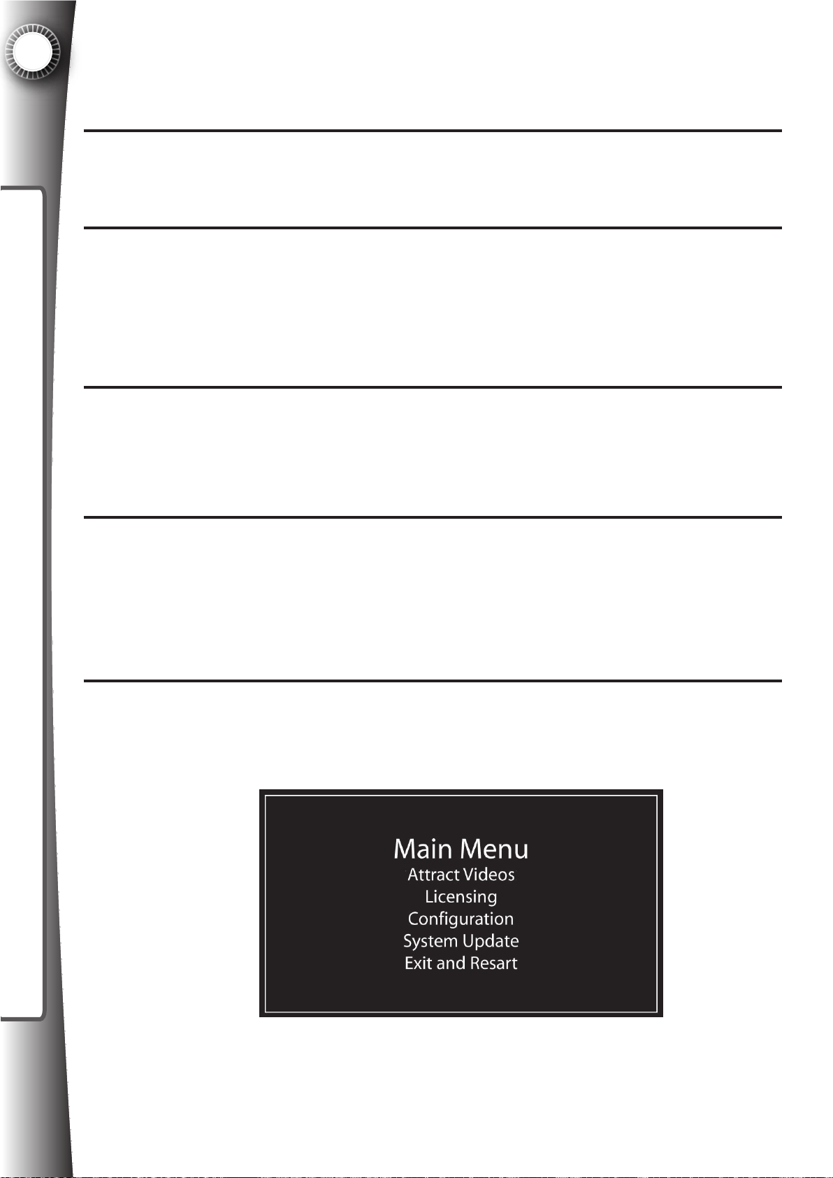
behind the coin door. A menu will appear on the screen. Use the “One Player Game”,
button to navigate to the “Licensing” option. Press the “Reset” button to conrm the selection.
ACTIVATION & RENEWAL
(Note: Licensing options are also available in the graphical interface under Advanced
Options, Section 6.2e.)
Select the option “Write Request to USB” by pressing the “Reset” button.
3
A le named “control.gamegate” will be saved to the USB ash drive. Follow the
prompts and remove the USB ash drive as requested. Repeat this process for all
Game Gate equipment that you own, you can use the same USB ash drive for all units.
55
Page 64
5
ACTIVATION & RENEWAL
4
5
6
7
Take the USB ash drive to a computer with an internet connection and insert in an
available USB port. Start your browser, such as Internet Explorer, and enter www.gamegatecontrol.com into the address bar.
Login to your account by entering your login and password. Click “Manage Units” and
click the “Renew” button. Follow the prompts to search for the le located on your USB
ash drive, which was saved in Step 3 above. Click “Submit”.
A list of the current Game Gates eligible for renewal will appear with a checkbox next
to each unit. Day credits required to update each unit are displayed as well as the day
credits available to apply to eligible machines. By default, all valid units will be unchecked. Check the box for any unit you wish to renew which will reduce the available
credits by the specied amount. Click “Conrm” to apply the day credits to the checked
unit(s).
A window will appear (varies by browser you are using) asking you to save a le (In
Internet Explorer select “Save” or Mozilla Firefox select “Save As”). Save the le to a
folder on your computer where you can nd it easily, such as the desktop. NOTE: The
le is also named “control.gamegate”, but it is a newer version of the original le upload-
ed in Step 3.
8
9
Copy this le directly to the USB ash drive using standard copy and paste techniques.
For example, locate the new le on your computer, right click the le and chose “Copy”.
Next browse for the USB ash drive and open the USB ash drive folder. Right click in
the window and choose “Paste”. You will be asked if you want to overwrite/replace the
le. You must overwrite the le so that the USB ash drive has the newer version of this
le, which includes the data necessary to complete the activation of your equipment.
Take the USB ash drive to the Game Gate(s) you wish to activate. Power on the Game
Gate and wait for “Please Wait” to end on the LED display. Insert the USB ash drive
into the USB port on the Game Gate. The following screen will appear.
56
Page 65
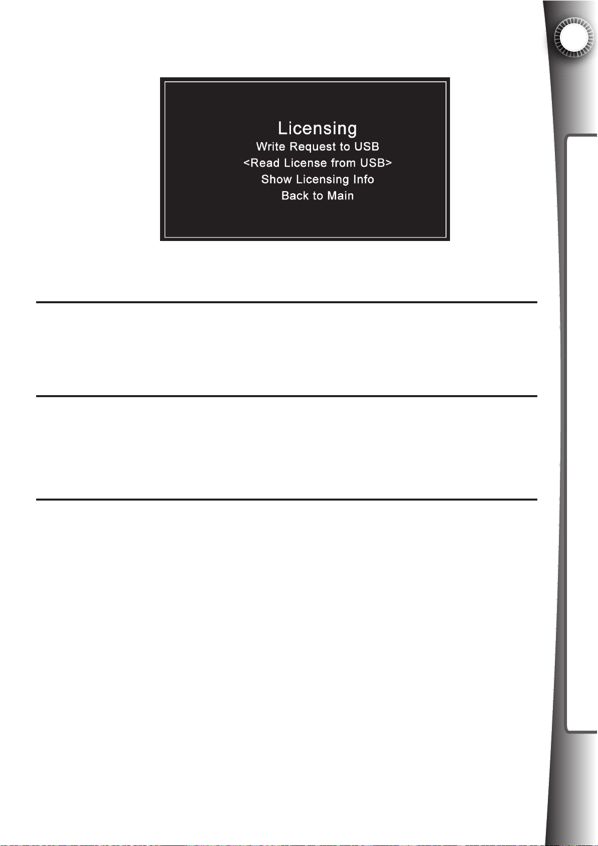
10
11
Using the “One Player Game” button, cycle down to “Licensing” and press the “RESET” button to select. The following screen will appear:
Use the “One Player Game” button to scroll, and press “RESET” to select “Read
License from USB”. The new le from the registration server will be located and your
machine will update.
5
ACTIVATION & RENEWAL
Follow the onscreen prompt to remove the USB ash drive. A screen will appear dur-
12
ing the reboot sequence that will show the new license status (Active). Renewal date
will be extended 6 months. Repeat steps 9 through 12 for all machines you chose to
renew in the registration server in Step 6.
5.5 When To Renew?
You will receive an invoice from the license manager at least 30 days prior to expiration. You
must pay this invoice in order to extend the activation. You may, at your option, choose to
have your credit card on le with the license manager to make the process more convenient.
Once you have paid the renewal fee, the license manager will add “Day Credits” to your account.
Currently, the maximum allowed extension time is 6 months, or approximately 182 days. So,
you will receive an invoice for $8 per month x 6 months = $48USD (per machine) prior to
expiration. You must logon to the registration server to apply the credits to the Game Gate™
VU equipment. A renewal le will be placed on the USB ash drive, which can be taken to
all Game Gate™ VUs that you wish to renew. Or, in the case where the Game Gate™ VU is
connected to the Internet, this extension can be pushed through the network so that visiting
the equipment is unnecessary (feature not available in all areas).
57
Page 66

5
What is the Master Renewal date?
Quasimoto wants the process for activation and renewal of equipment to be as easy as possible. Therefore, if you have purchased and/or activated multiple Game Gate™ VU units on
different dates, our system will synchronize the renewal dates of all the units to the same date
so that you don’t have to worry about multiple expiration dates. This means that no matter
how many machines you have, you will only be billed twice a year and have to renew twice a
year.
ACTIVATION & RENEWAL
What Are Day Credits?
Every new Game Gate™ VU includes 6 months of free license. In order to synchronize multiple units the unit of measure is in days instead of months. Therefore, each new unit comes
with 182 days of credit (leap years and extra days are added in favor of the licensee). The
license manager will bill you in month 5 for an additional 182 Days Credits to apply to extend
the license, which are applied to your account upon receipt of payment (again $8 per month
per machine). The examples below show two circumstances of how Day Credits are applied
and how Day Credits affect multiple units. Note that there are only two expiration dates in
a year regardless of how many units are owned and when the units are activated. The rst
renewal date is set during initial activation will and always be the renewal date for the equipment, so mark your calendar!
Example 1: First machine is activated on Jan 1, 2010
- 182 free Day Credits are applied
- Master renewal date is Jul 1, 2010
- Invoice from the license manager for 182 Day Credits.
- Payment received before Jul 1, 182 Day Credits added to account.
- Owner logs into registration server and applies credits.
- Owner updates equipment, new renewal date is Jan 1, 2011
- Cycle repeats
Example 2: Second machine is activated on Feb 1, 2010
- Master renewal date remains Jul 1, 2010 (see #1 above)
- 152 free Day Credits are applied (to reach Jul 1, 2010)
- Balance of 30 Day Credits remain on account
- Invoice from license manager for 182 day credits (machine 1) plus
152 days (182 - 30) Day Credits unapplied = 334 days
- Payment received before Jul 1, 334 day credits added to account.
- Owner logs into registration server and applies credits.
- Owner updates machine 1 and 2, new renewal date is Jan 1, 2011.
- Next billing cycle, license manager will bill for 364 days (182+182)
- Cycle repeats.
58
Page 67
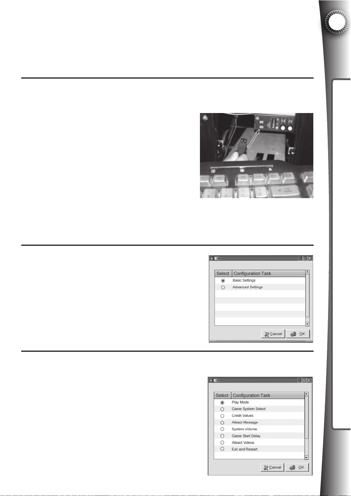
6. SYSTEM SETTINGS
Now that the equipment is activated, you must set up the important parameters for operation,
(such as cost per minute, cost per player, volume, etc.) as well as make sure the game console
is properly set up for optimal user experience.
System settings can be adjusted in one of two ways: 1) Directly on the unit using a USB keyboard/mouse.
Adjust System settings with a USB keyboard and/or
mouse. Power the Game Gate™ VU on by pressing the
power switch on the back panel of the machine. Wait
for the LED matrix to go past the “PLEASE WAIT” message while the system is loading.
Once the Game Gate™ VU is in attract mode, open the
coin door to gain access to the Game Gate™ VU user
panel. On the panel, locate the two USB service ports.
You will need at a USB keyboard and/or mouse to adjust the system settings. Using both will make menu
navigation more efcient.
Note: Make sure that you are not currently playing a game (Game Mode) and that the
equipment is in the attract mode before connecting any USB device,
or the system will not go into the setup mode.
Fig. 6A
6
SYSTEM SETTINGS
Upon inserting a USB keyboard, a window will appear on
the LCD display:
If you are using a keyboard, press SPACEBAR to select a
button and press the arrow keys to cycle to the OK button.
Pressing ENTER will take you to the next screen. If you
are using a mouse, simply click the OK button.
Fig. 6B
6.1 Basic System Settings
Under the “Basic Settings” options, you will be able to adjust the most important options such as Play Mode, Console Used, Attract Message, System Volume, Game Start
Delay, and Attract Videos. Once you have made changes,
move back to this screen and click “Exit and Restart” or
press the ESC key to save the new settings.
IMPORTANT: You must unplug the keyboard and mouse Game
Gate™ VU before the system restarts or the system will lock up
until removed.
Fig. 6.1A
59
Page 68
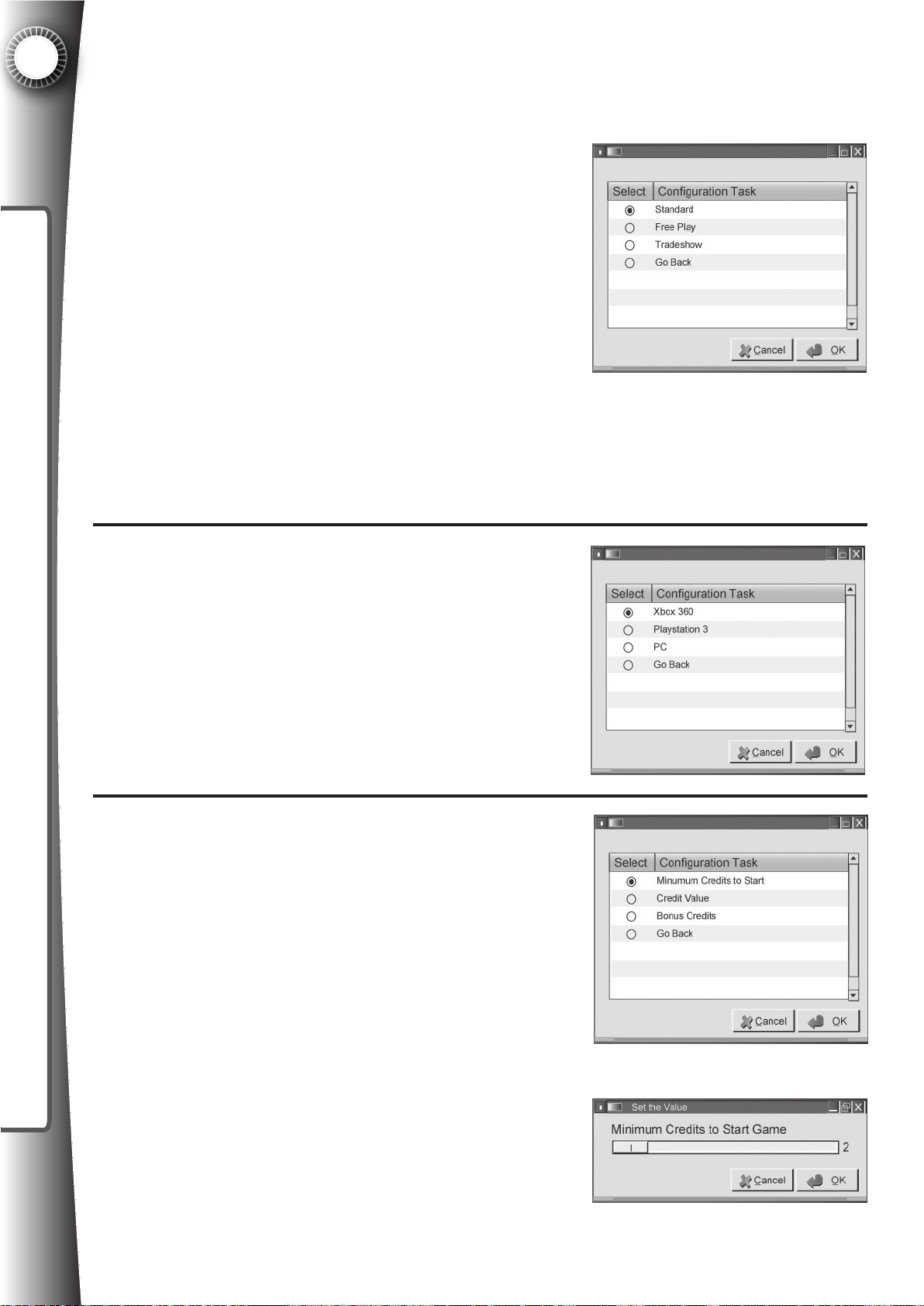
6
SYSTEM SETTINGS
Basic Settings: Play Mode
Selecting Play Mode and clicking OK will take you to the following screen:
Standard - Select this is the mode if you wish to charge
patrons for playing Game Gate™ VU. This mode requires
the player to insert credits to operate a game and activate
one or two players. (This mode functions as Free Play mode
if the unit is not yet registered and activated.
Free Play - Select this mode if you want to have the game
console and controllers on at all times. Games are free to
play and there will be no custom attract videos.
Tradeshow - Use this mode if you want the games to be
a free play but still want to have the attract videos. In tradeshow mode, credits are added by
pressing the ashing RESET button on the front of the cabinet. Credit values are locked in this
mode and setting changes will not be saved.
Select a mode for the Game Gate™ VU and click “Ok”.
Basic Settings: Game System Select
Chose the game system that you are using in the Game
Gate™ VU and click OK, which will take you back to the
Basic Options page. Default system is Xbox 360®.
Xbox 360® - a Microsoft® product
PLAYSTATION®3 - a Sony® product
PC - support coming soon
Fig.
6.1C
Fig. 6.1B
Basic Settings: Credit Values
Minimum Credits to Start - Set the number of credits to
start a game by sliding the bar to the left or right using the
arrow keys on the keyboard or by dragging with the mouse.
Click “Ok”.
For example, if a credit is 25 cents and you want to have
a 50 cent minimum to start a game, adjust the value to 2.
Default value is 2 credits to start.
60
Fig. 6.1D
Fig. 6.1E
Page 69
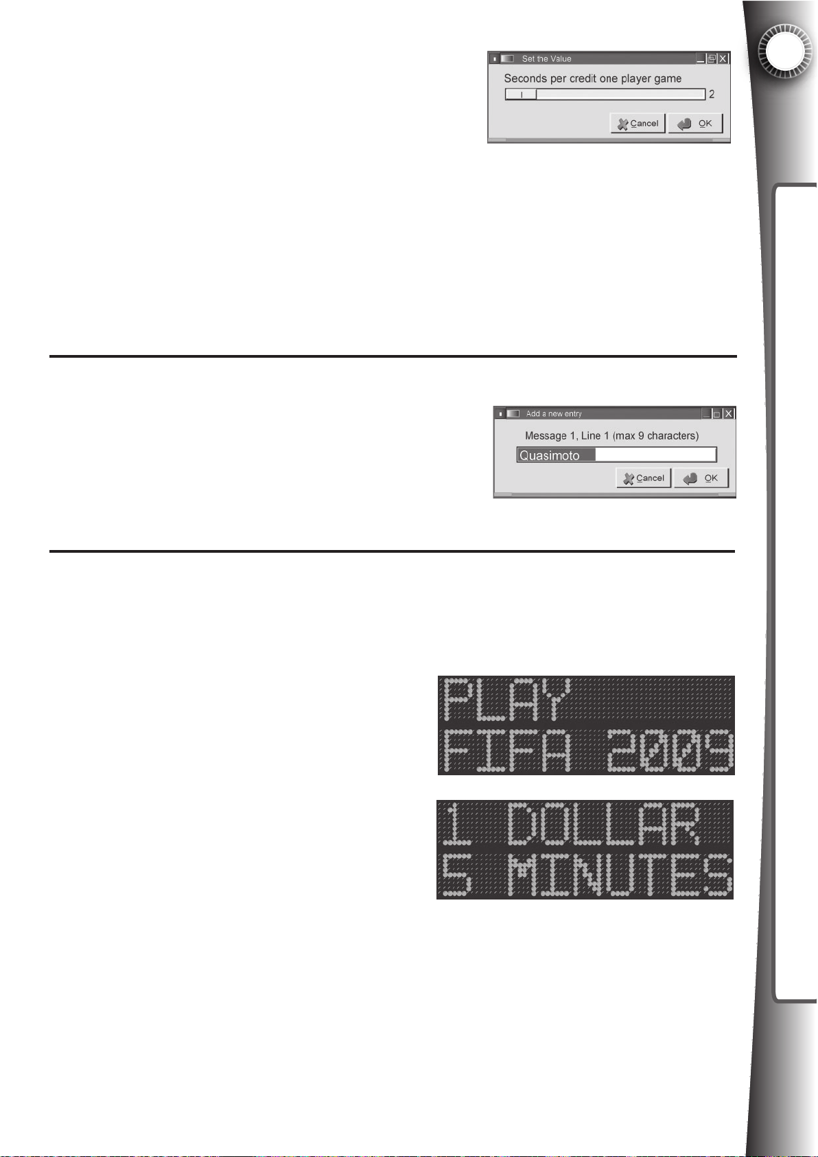
Credit Value - Set the number of seconds that will be given to the player for a single credit on a one player game.
Set the number of seconds by sliding the bar to the left or
right using the arrow keys on the keyboard or by dragging
with the mouse.
For example, if you wish to have one credit give 60 seconds
of play, adjust the value to 60. If one credit is 25 cents, this means that one dollar (4 credits)
will give one player four minutes to play. Default value is 75 ($1=5 minutes). Also, if a 2-player
game is started, the seconds will be divided in half. In the example just given, this means that
one dollar of play would give both players two minutes and thirty seconds
to play. Click “Ok”.
Bonus Credits - If you wish to give players a discount at a certain credit level, select this option to make adjustments.
Basic Settings: Attract Message
The Attract Message setting will change the message displayed on the LED matrix in the Game Gate™ VU header
during the attract mode. Use this area to create your own
messages to promote the game in the machine, communicate the cost per player, and pass any other message (ie.
drink specials, venue name, etc).
Fig. 6.1G
6
SYSTEM SETTINGS
There are 8 messages, with each message having two lines with up to 9 characters per line.
Use the keyboard to enter up to 9 digits, including spaces, for the display screen and press
OK to go to the next line/message. The LED matrix will display two lines per message and
play each message in order from 1 to 8.
For example:
Message 1, Line 1: “PLAY” will appear as:
Message 1, Line 2: “FIFA 2009” will appear as:
Fig.
6.1H
Message 2, Line 1: “1 DOLLAR” will appear as:
Message 2, Line 2: “5 MINUTES” will appear as:
Fig.
6.1I
Lower case will also work in the display as well as standard symbols and characters. Use
spaces to center text.
The default message is: “Quasimoto, Game Gate™ VU; Converts,Home Game; Consoles,
Into; Play, by Time; Game, Machines; 1 Dollar, 5 minutes; Per, Player; Get in, the Game!”
The last two messages, message 9 and 10, are reserved for an emergency call out that is
triggered by the emergency jack signal. Default message is “FIRE, ALARM!; PLEASE, END
GAME”
61
Page 70
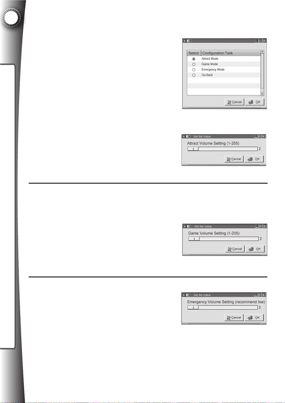
6
SYSTEM SETTINGS
Basic Settings: System Volume
Refer to Section 3.5 for master volume settings
Attract Mode - The volume level when the game is attracting players and no credits have been inserted. During attract
mode the game preview, game instructions, and uploaded
video advertisements will play at the set volume. Values
range from 0 (no volume) to 255 (max volume). Many operators have seen that a lower attract volume in certain venues
will deter venue employees from unplugging the equipment.
Set the volume level by sliding the bar to the left
or right using the arrow keys on the keyboard or
by dragging with the mouse. Default value is 200.
Click “Ok”.
Fig. 6.1J
Fig. 6.1K
Game Mode - The volume level when credits have been inserted and the game is being
played. Values range from 0 (no volume) to 255 (max volume). It is recommended to have
the game volume higher than the attract volume, but should be set to venue preference.
Set the volume level by sliding the bar to the left or
right using the arrow keys on the keyboard or by dragging with the mouse. Default value is 255. Click “Ok”.
Fig. 6.1L
Emergency Mode - This is the volume level if the emergency jack on the back of the cabinet is connected and
a signal is received. The emergency mode is for venues that have a re alarm and must make important announcements (for example, an airport). The emergency volume should be set much lower than the
Attract Mode volume or Game Mode volume so that patrons can hear the announcement.
Fig. 6.1M
Set the volume level by sliding the bar to the left or right using the arrow keys on the keyboard
or by dragging with the mouse. Default value is 0. Click “Ok”.
62
Page 71
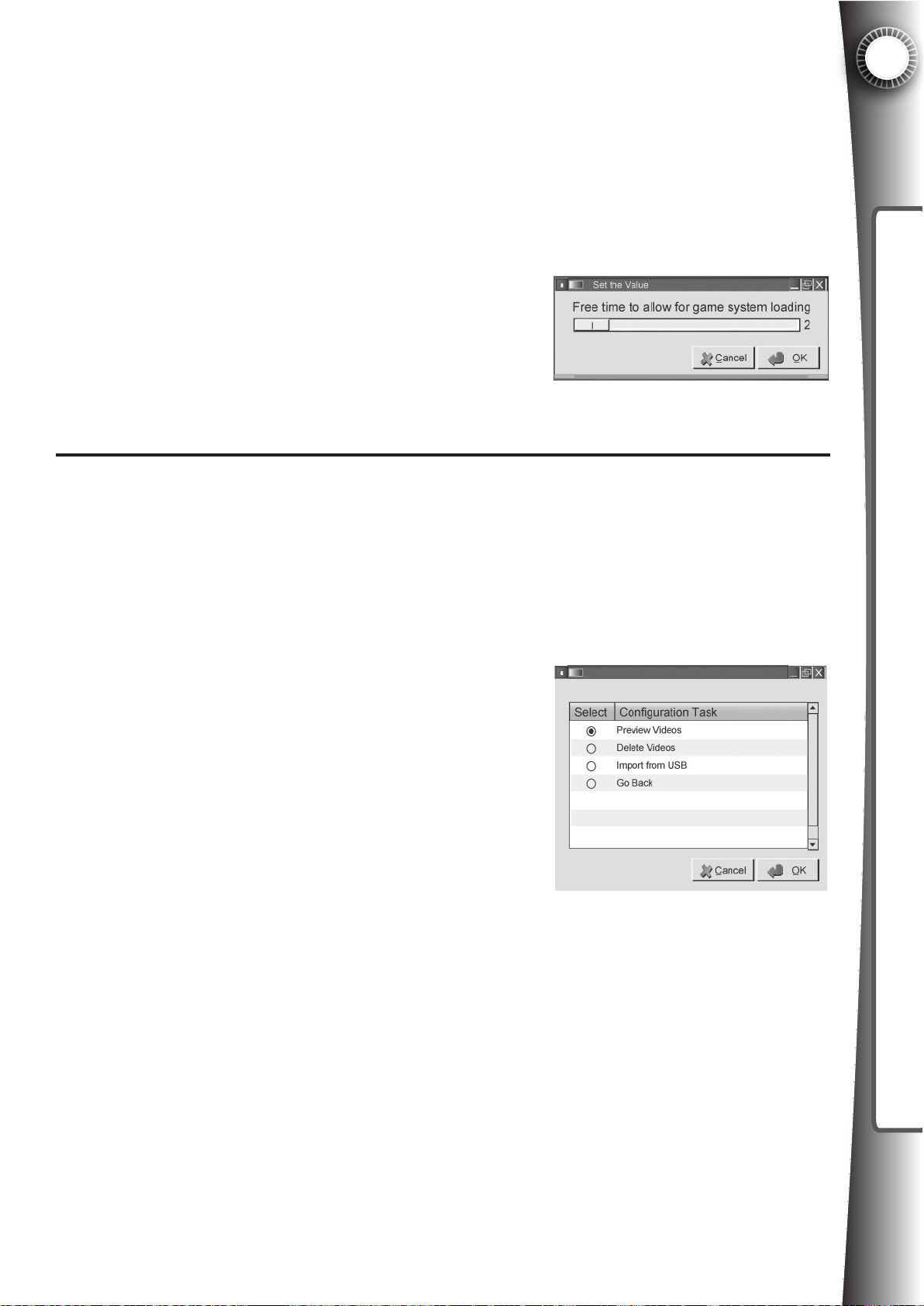
Basic Settings: Game Start Delay
The Game Start Delay is an important time value that ensures a positive player experience.
Video games vary greatly in the amount of time it takes to navigate menus and load before
game play will actually begin. The Game Start Delay is the amount of free time to allow to begin
a new game; the amount of time that will pass before the timer starts to count down. Games
that have a long load time in the beginning should be assigned a longer Game Start Delay to
account for this time. The Game Start Delay is free time that is only given on the start of a
new game, not the continuation of a game that is already in
progress.
Set the number of seconds by sliding the bar to the left or
right using the arrow keys on the keyboard or by dragging
with the mouse. Click OK to return the previous menu. Default value is 60 seconds.
Fig. 6.1N
6
SYSTEM SETTINGS
Basic Settings: Attract Videos
The Attract Videos section allows you to preview and delete the videos that are currently loaded
into the Game Gate™ VU. When the Game Gate™ VU is not being used by a player (no credits inserted), the Game Gate™ VU will play videos on the LCD to attract the player and inform
the player how to get the game started. The Game Gate™ VU is designed to work with many
le formats, such as AVI, MPEG, and WMV. We recommend les that are high denition 720p minimum for the
best picture and audio quality. The Attract Videos must be
uploaded into the Game Gate™ VU through a USB ash
drive, in a folder named “GGvideo” (case senstive). Create
this folder using a computer browser.
Preview Videos - lists the videos loaded in the Game
Gate™ VU. Scroll down to select a video to preview. Select “Go Back” to return the previous menu. Click “Ok” when
selection is made.
Delete Videos - delete the videos that you no longer wish to run in the attract sequence. Select
“Go Back” to return the previous menu. Click “Ok” when selection is made.
Fig. 6.1O
Import from USB - select this option to upload the videos from the USB ash drive. Use a personal computer to copy video les into the folder “GGvideo” (case sensitive) on any USB ash
drive. You can create this folder in the root directly of a USB ash drive for the same effect.
Videos can be uploaded through the onscreen setup menu. Select “Import from USB” and follow the prompts to insert the USB stick into the USB port on the user panel. Click OK to return
to the previous screen. Go to the “Preview Videos” section to conrm a successful upload.
63
Page 72

6
The Advanced System Settings section includes all the Basic System Settings (detailed in Section 6.1) and more detailed system settings for users that wish to take advantage of the full set
of options available with the Game Gate™ VU. System settings can be adjusted in one of two
ways 1) directly on the unit using a USB keyboard/mouse or 2) through an Internet connected
computer via the registration server. This section is a guide to the Advanced System Settings
SYSTEM SETTINGS
menu system directly on the unit via a keyboard and/or mouse. Navigate the menus the same
as shown in the basic settings (Section 6.1).
The Advanced System Settings are grouped by function (settings which control how the unit operates, network settings, and maintenance functions are grouped under menus for those tasks).
The initial menu options are as follows:
6.2a System Information - Displays general information about the unit such as
software version and free memory amount.
6.2b Video Management - Management of attract mode videos. Detailed in Basic
System Settings.
6.2c Network Settings - Allows conguration of network interface to allow the unit
to connect to the Internet.
6.2d Operation Settings - Conguration of unit’s operation parameters, such as
credit values, timings, and volume.
6.2e Licensing - View current license information, request, or upload licensing
information.
6.2f Maintenance - Perform system maintenance tasks.
6.2 Advanced System Settings
6.2a Advanced Settings: System Information
This option will display a window showing the current software and rmware versions of the
unit, as well as memory in use by attract videos, and the amount of free memory remaining.
6.2b Advanced Settings: Video Management
See Section 6.1
6.2c Advanced Settings: Network Settings
This option allows you to change the network settings for the Game Gate™ VU unit. The
benets of connecting a Game Gate™ VU unit to the Internet include checking activity/maintenance logs, changing settings, and automating license renewal for all your Internet-connected
units from one Internet-connected computer. Game Gate™ VU requires broadband connection and is not dial up Internet compatible. Broadband connection and internet fees are the
responsibility of the proprietor.
Show Current Settings - This option displays a window containing your unit’s current net-
work conguration. This includes connection type (DHCP or Static), IP address, Subnet mask,
Gateway, and DNS servers.
Change Settings - This option allows you to change your connection type. DHCP auto-
conguration and static addressing are supported. If static is chosen, the unit will guide you
through a short series of dialogs to set your IP, netmask, and other settings. If your unit is
equipped with a wireless networking add-on, the change settings dialogs will include choosing
64
Page 73
between a wired and wireless connection, and searching for or manually setting any appropriate wireless network settings.
Test Connection - This option performs a test of your network and internet connection. This
can help determine if your chosen settings are correct, and that your connection is operating
properly.
6.2d Advanced Settings: Operation Settings
Settings under “Operation Settings” affect how the Game Gate™ VU unit operates. Many of
these options are already coved in Section 6.1 “Basic Settings”. Those options present in both
Basic and Advanced menus operate identically.
Operation Mode - see Section 6.1
Console System - see Section 6.1
Credit Values - see Section 6.1
6
SYSTEM SETTINGS
Marquee Message - see Section 6.1
System Volume - see Section 6.1
System Timings
These options represent some of the timing values that may need to be adjusted to ensure
smooth operation and optimal user experience.
Coin Mechanism - This option sets the pulse delay for the coin mechanism a
ttachment. Please consult your coin mechanism documentation for the appropriate
setting. Default is 200ms.
Bill Acceptor - This option sets the pulse delay for the bill acceptor attachment. Please
consult your bill acceptor documentation for the appropriate setting. Default is 200ms.
Marquee Scrolling - This option controls the rate at which the message on the LED
marquee changes. Lower values cause the display to change more frequently, leaving
a given message up for less time before changing. Default value is 6.
Game Start Delay - see Section 6.1
Misc. Options
Xbox 360® Kiosk Mode - This toggle controls whether or not a connected Xbox 360®
is set in “Kiosk Mode”. In Kiosk Mode, the center guide button on the Xbox controller
will not function (instead bringing up an informative window), thusly preventing the user
from escaping the game to the Xbox 360® dashboard where they could otherwise alter
important settings on the Xbox 360® console. This option is defaulted to ON.
Add 2P Without Reboot - Very few games allow the addition of a second player mid-
game. The standard behavior of the Game Gate™ VU is to reset the game console
when adding a second player mid-game. This setting will override the standard behav
ior, allowing the user to add a second player during play without resetting the console.
As very few games support this, the option is defaulted to OFF.
65
Page 74

6
This section provides options for handling the Game Gate™ VU licensing. Access this setting
to: manually attempt to renew a license, to extend the activation to the next renewal date. See
Section 5, for more information about the activation and renewal process.
Export License Request - This option will prompt you to connect a USB memory device if you
SYSTEM SETTINGS
have not already done so. The unit will then write out a license request to the USB memory
device.
Import License Response - This option will prompt you to connect a USB memory device if
you have not already done so. The unit will search the ash device for a valid license response
from the online registration server and apply it.
Request from Server - if your Game Gate™ VU is connected to the Internet, this option will
cause the unit to connect to the registration server and acquire any valid license updates. This
should generally not be necessary for Internet-connected units as they will periodically request
this information on their own. Online licensing may not be available in some areas.
Display License Information - This option will present a window displaying current license
information such as length and expiration date.
6.2e Advanced Settings: Licensing
6.2f Advanced Settings: Maintenance
Contained under this option are procedures which are unlikely to be needed on a regular basis,
but can be used to diagnose or correct some malfunctions in a Game Gate™ VU unit.
Review Maintenance Log - Selecting this option will present a window containing the maintenance log of the Game Gate™ VU. This log tracks all maintenance procedures, including the
dates and times they are performed.
Maintenance: Empty Currency - This option will display the current credit count in the machine, and present the option to reset the counter. This is primarily used when the coin bucket
and/or bill acceptor magazine are emptied. The currency count can be compared to actual currency in the unit to aid in the detection of theft or device malfunction. Emptying the currency and
resetting the counter will add an entry to the maintenance log detailing when the procedure was
performed, and the currency counter value at that time.
Date and Time - Occasionally the internal clock of the Game Gate™ VU unit will need set to
the correct date and time. This option allows you to set the date and time accordingly, and adds
an entry to the maintenance log detailing both original date/time and the newly set date/time.
Test Audio/Video - This option allows you to run tests of the audio and video systems. The
audio system can be tested for left/right stereo sound and high/low frequency. The high and low
frequency tests should cause the unit to emit a tone which should very smoothly transition from
a low pitch to a high pitch. Distortion or crackling noises are indicative of damaged equipment.
The video test will cause the LCD screen to cycle through several screens of solid colors, followed by several screens of grid layouts. Colors should appear solidly uniform across the entire
screen, and the grid lines should appear crisp and straight.
System Maintenance - These functions are generally reserved for in-depth troubleshooting
and system repair.
66
Page 75
Flash System Firmware - This option will ash the base system rmware of the Game Gate™
VU unit. This option should only be used at the direction of technical support personnel. Incorrect usage can cause the Game Gate™ VU unit to operate incorrectly and necessitate major
repair.
Run Troubleshooter - Activating this option will cause the system to enter a troubleshooting
mode. This should only be done at the direction of technical support personnel. Not available
on all units.
Enter Debug System - Not available on all units. This option allows the operator to access a
debug interface.
Conguration Data - A Game Gate™ VU unit stores conguration data internally. This information can be written out to a USB ash memory device for backup. Alternatively, a Game Gate™
VU can import conguration data from a USB ash memory device and recongure itself ac-
cordingly.
Export Conguration Data - This option will prompt you to connect a USB ash device if you
haven’t already done so, and then update it with the current conguration details of the unit.
6
SYSTEM SETTINGS
Import Conguration Data - This option will prompt you to connect a USB ash device if you
haven’t already done so, and then import any valid conguration data from the ash device.
Conguration data is stored uniquely to each machine on the ash drive, so a given unit can
only import data that it has previously exported, or has been generated by the online registration server.
Restore Factory Defaults - This option will reset the unit’s settings back to factory specications. This does not erase any software or rmware updates that the unit has received. All set-
tings stored previously are lost.
67
Page 76
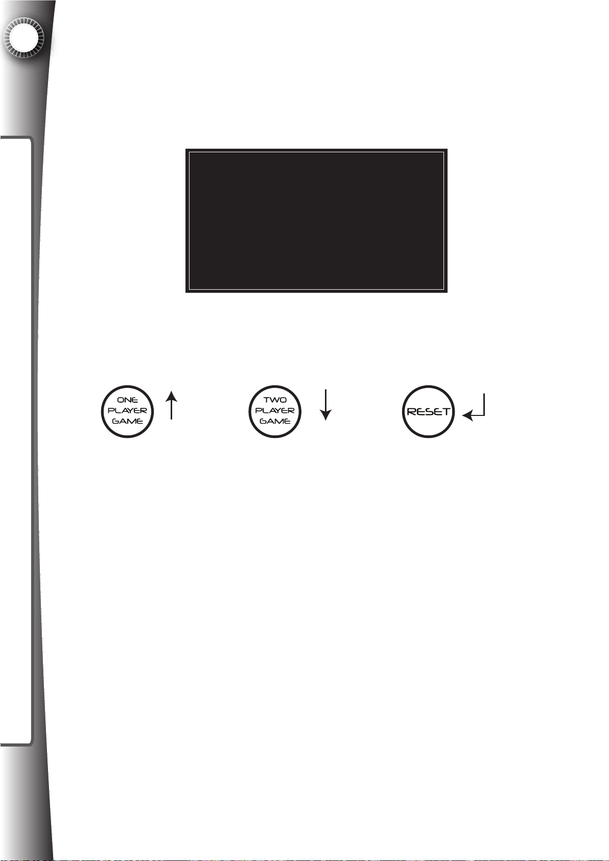
6
Main Menu
<Attract Videos>
Licensing
Configuration
System Update
Exit and Resart
When a USB memory device (such as a thumbstick or other ash drive) is connected to the
Game Gate™ VU before a keyboard or mouse is connected, a menu will appear after a short
delay. This menu system is navigated with the buttons already present on the cabinet. The initial menu appears as below.
SYSTEM SETTINGS
6.3 USB Flash Drive Menu
The option with “<” and “>” on either side is the currently highlighted selection. “One Player
Game” button moves the selector up, “Two Player Game” button moves the selector down, and
the “RESET” activates the highlighted selection.
UP
In brief, the function of each menu item is as follows:
Attract Videos – Allows importing of videos from USB device, or entry to video manager.
Licensing – Allows viewing and updating of licensing information.
Conguration – Used for transferring conguration data to/from USB device.
DOWN
Fig. 6.3A
ENTER
Fig. 6.3B
System Update – Allows update of Game Gate™ VU system software and rmware.
Exit and Restart – Finalizes any changes and restarts the unit.
Each of the above menu options presents a submenu with the exception of Exit and Restart.
The layout and function of each submenu is detailed below. Menu navigation remains the same
throughout the submenus as it does for the main menu.
68
Page 77
ATTRACT VIDEOS
Import USB (keep existing) – Import video les from the “GGvideo” folder of the ash device
into the unit’s library of attract mode videos. This option leaves any existing video les on the
unit.
Import USB (clear existing) – Import video les from the “GGvideo” folder of the ash device
into the unit’s library of attract mode videos. This option erases any existing video les on the
unit prior to import.
Video Management – This option will prompt for the user to connect a USB keyboard or mouse
to a USB service port on the unit to make use of the video management feature (this feature is
detailed along with the standard conguration system). Pressing the “1 Player Game” button
during this prompt will cancel and return to the main menu.
LICENSING
Write Request to USB – Generate a License Request and write it to the USB memory device.
This is a necessary rst step to activate and/or renew a unit’s license.
6
SYSTEM SETTINGS
Read License from USB – Read a License Response from the USB memory device. License.
Responses are generated by the Game Gate™ VU Licensing server and should be downloaded to the USB memory device. If a valid license has been obtained and downloaded to the USB
memory device, this option will activate the unit.
Show Licensing Info – Display current license status, as well as other information such as
date of activation and expiration.
CONFIGURATION
Write to USB – Copy the unit’s current conguration settings to the USB memory device. This
does not include the video les in the unit’s attract mode video library or license data.
Read from USB – Read conguration information from the USB memory device and apply it to
the unit. This does not include license information or video les.
Cong Manager - This option will prompt for the user to connect a USB keyboard or mouse to
a USB service port on the unit to make use of the conguration management feature. Pressing
the “1 Player Game” button during this prompt will cancel and return to the main menu.
SYSTEM UPDATE
Update from USB – This option causes the unit to search for valid system updates residing on
the USB memory device. If a valid update to a newer version of system software is found, it will
be applied immediately.
Update Online – This option causes the unit to contact the Game Gate™ VU servers on the
internet to request any software updates. Any valid updates will be downloaded and applied.
(NOTE: THIS FEATURE MAY NOT BE FUNCTIONAL IN YOUR AREA)
69
Page 78
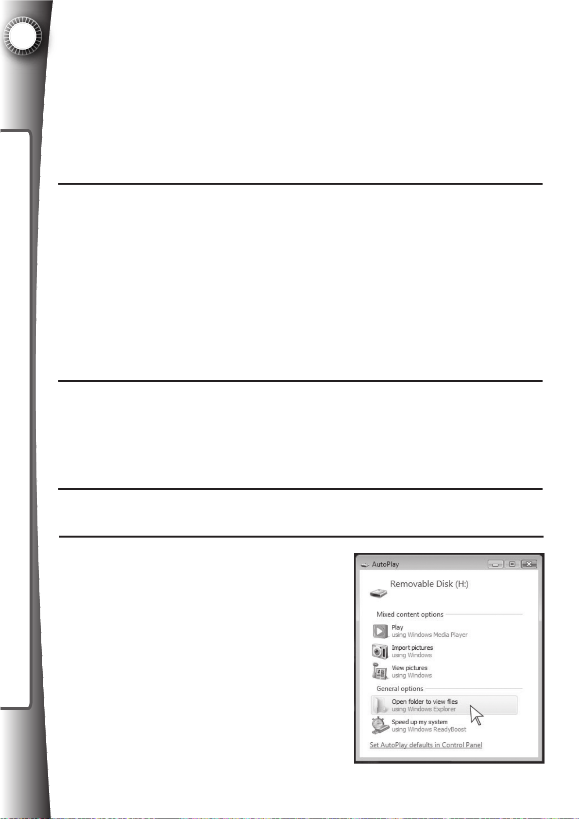
6
Overview
When the Game Gate™ VU is not being used by a player (no credits inserted), the Game
Gate™ VU will play videos on the LCD screen to attract the player and inform the player how to
get the game started. The Game Gate™ VU is designed to work with many le formats, such
SYSTEM SETTINGS
as AVI, MPEG, and WMV. We recommend les that are high denition 720p minimum for the
best picture and audio quality. The Attract Videos must be uploaded into the Game Gate™ VU
through a USB ash drive, such as the one included with each machine.
What Videos to Use
Quasimoto recommends that the videos displayed include at least one video clip of the current
game being played in the machine, such as a game trailer. High denition game trailers can be
found through internet searches on websites such as www.gametrailers.com.
It is also possible to load commercials for products, movie trailers, and other consumer notice
videos. Such videos can be sold as advertising opportunities. If you have a good location, this
is an alternative revenue opportunity in operating Game Gate™ VU.
6.4 Attract Videos
Video les will play in random order. To increase the frequency of particular videos, simply create more copies (with a slightly different le name) to increase the odds that a particular video
will play.
How to Load Videos
To load video les into Game Gate™ VU, you will need a computer and a USB ash drive, such
as the one included with the equipment. The example below assumes that the computer is running a Windows based operating system, but the principle remains the same regardless of the
operation system being used.
Insert the USB ash drive to an available USB port on the computer.
1
Click “Open folder to view les” to view the les
2
and folders on the USB drive.
70
Fig. 6.4A
Page 79
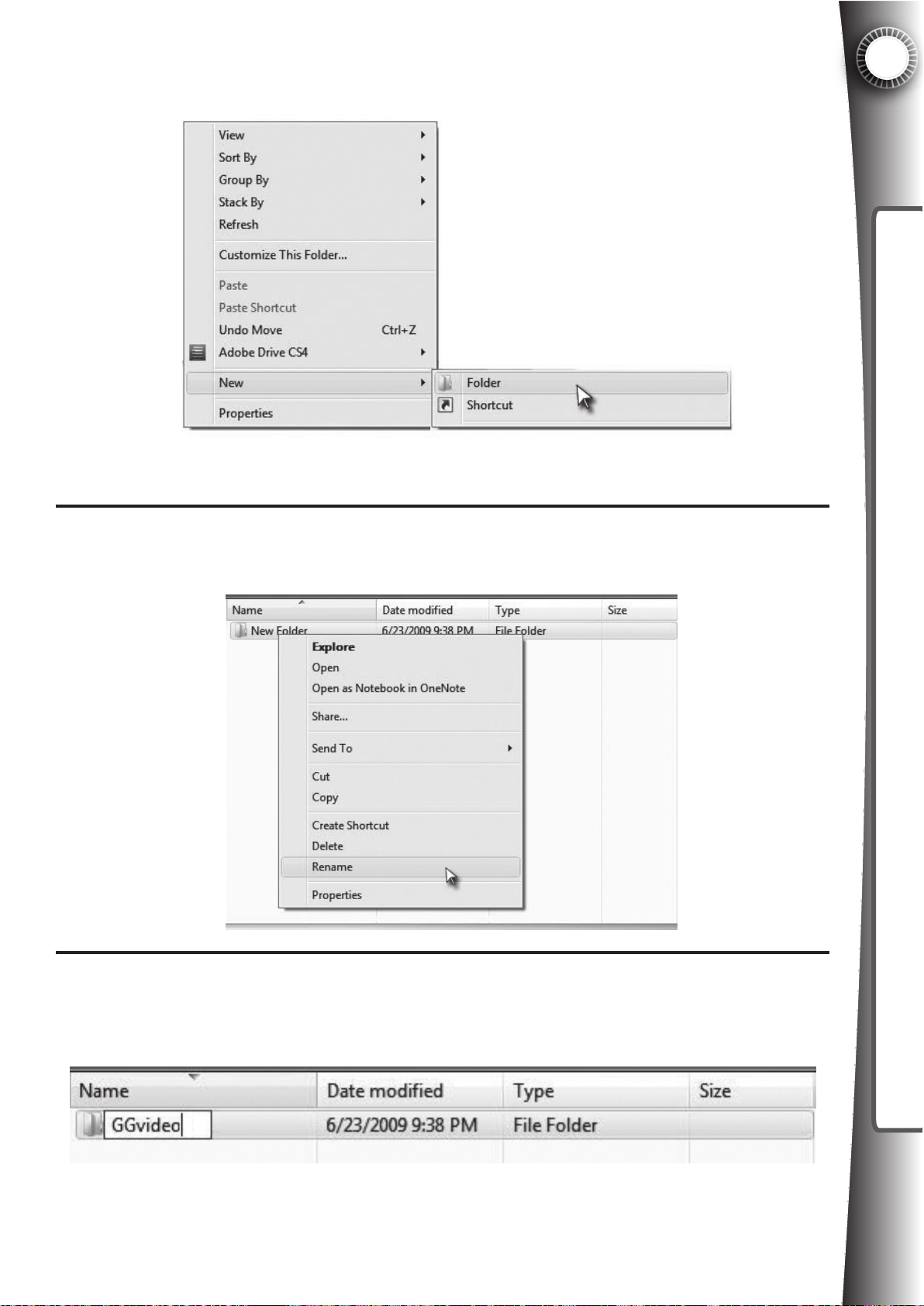
If a folder named “GGvideo” does not exist on the drive, right click the mouse button
and choose New>Folder.
3
6
SYSTEM SETTINGS
Fig. 6.4B
Right click on the “New Folder” and select “Rename”.
4
Name the folder “GGvideo”
5
Fig. 6.4C
Fig. 6.4D
71
Page 80
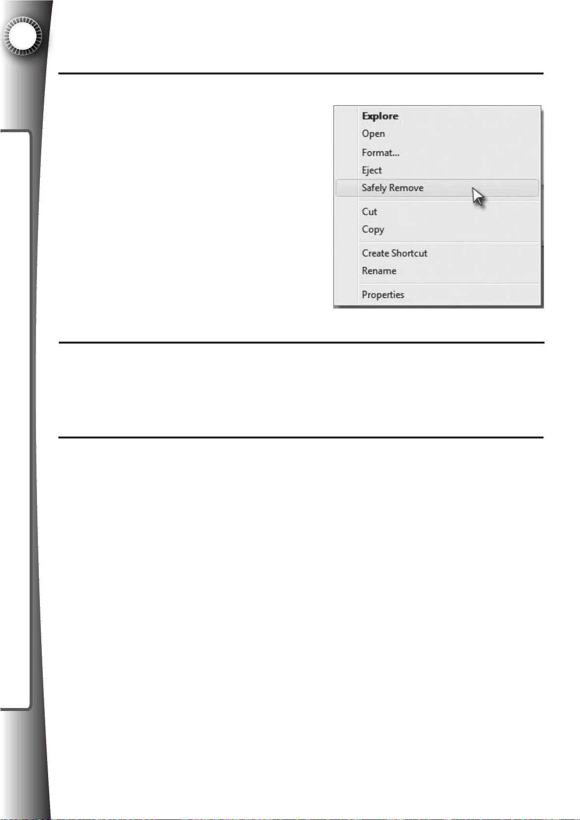
6
SYSTEM SETTINGS
Copy all of the video les you wish to play in Game Gate™ VU to this folder.
6
Go to “My Computer”, and right click on the
7
USB ash drive, select “Safely Remove”.
Remove the USB ash drive from the com-
puter.
Insert the USB ash drive into the USB port on the Game Gate™ VU user panel (lo-
8
cated behind the top coin door).
Navigate the setup menu (See Section 6.3 “USB Flash Drive Menu”) to upload the vid-
9
eos from the USB ash drive into the Game Gate™ VU.
Fig. 6.4E
72
Page 81
6.5 Optimizing The Xbox 360®
Some adjustments must be made to the XBox 360® to optimize the console for this application.
To make these adjustments the Xbox 360® must be on and showing video. To do this, make
sure there is no game disk in the DVD driver. Power on the Game Gate™ VU, allow it to load
until the “Please Wait” message on the LED matrix is no longer showing. Open the coin door
and press the Free Coin button to add at least 5 minutes of time. Then press the “One Player
Game” button. The system will boot and take you into the Xbox 360® dashboard to adjust the
console’s settings.
DISPLAY SETTINGS
In order to get the best possible video quality out of the Xbox 360® and the Game Gate™ VU,
set the XBox 360 to high denition widescreen, which is accomplished through the Xbox 360®
dashboard. Use the handheld controllers to move to the system settings and set the video to
720p WIDESCREEN (see the XBox 360® owner’s manual for more details). The video quality
will improve and games will now run in high denition.
6
SYSTEM SETTINGS
STARTUP SETTINGS
The Game Gate™ VU frequently resets the XBox 360®. The design of the system is that the
game disc in the drive must be detected and automatically started when the system boots.
Default settings with the Xbox 360® usually have this already enabled, but if the game is not directly booting and instead you are seeing the dashboard during boot, check the system startup
options in the dashboard to automatically boot to the disc. In the dashboard, go to the SYSTEM
tab, then scroll down to the STARTUP tab as shown and make the appropriate selection (see
the XBox 360® owner’s manual for more details).
73
Page 82
6
Some adjustments must be made to the PLAYSTATION®3 to optimize the console for this application. To make these adjustments the PLAYSTATION®3: Must be on and showing video. To
do this, make sure there is no game disk in the DVD driver.
• Power on the Game Gate™ VU,
• Allow it to load until the “Please Wait” message on the LED matrix is no longer showing.
SYSTEM SETTINGS
• Open the coin door and press the Free Coin button to add at least 5 minutes of time.
• Then press the “One Player Game” button.
• The system will boot and take you into the PLAYSTATION®3 dashboard to adjust the
console’s settings.
DISPLAY SETTINGS
In order to get the best possible video quality out of the PLAYSTATION®3 with Game Gate™
VU, set the PLAYSTATION®3 to high denition widescreen, which is accomplished through the
display settings section of the menu. Use the handheld controller to move to the system settings and set the video to 720p WIDESCREEN (see the PLAYSTATION®3’s owner manual for
more details. Once the video setting is conrmed, the video quality will improve and games will
now run in high denition.
6.6 Optimizing The PLAYSTATION®3
74
Page 83
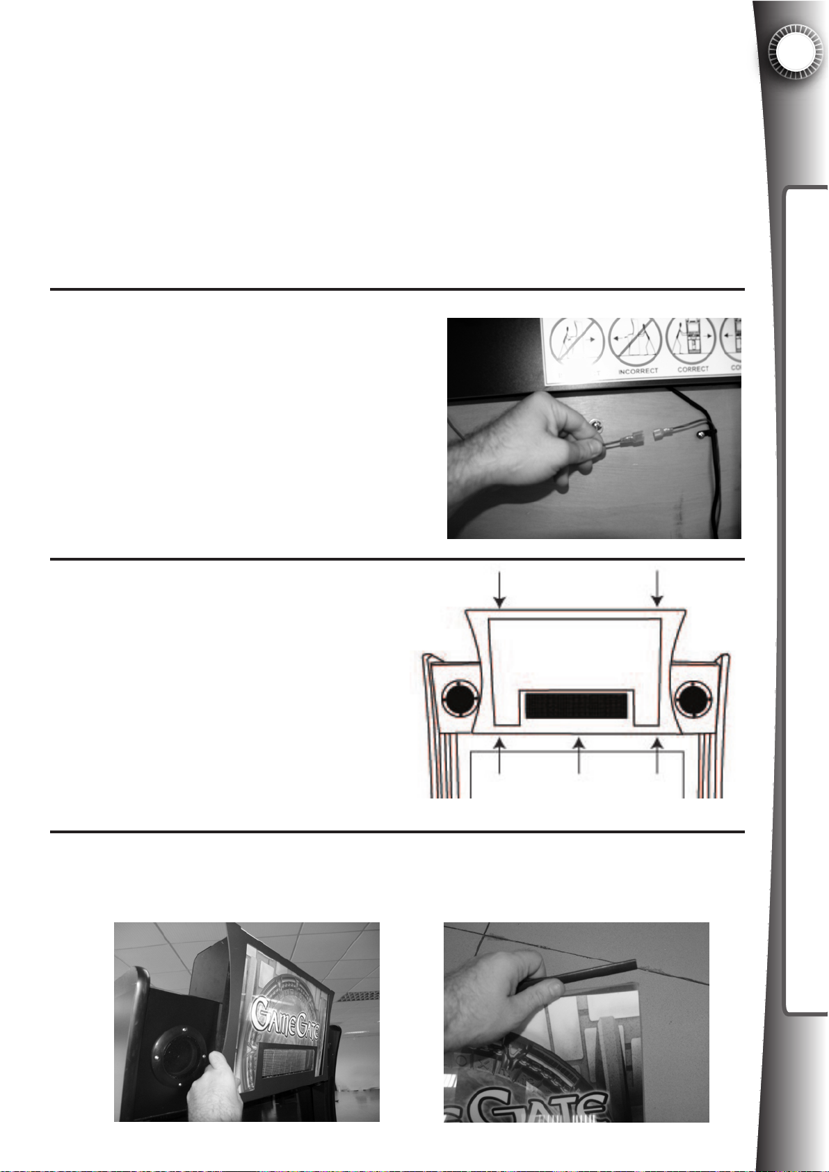
7. CUSTOMIZING THE APPEARANCE
The Game Gate™ VU has a modular graphic system “Quikskin”, which allows for the side
panels, marquee, and control panel to easily be updated to promote a specic game title. In
addition, the control panel has a slot to display the retail game case, which communicates the
game rating.
7
7.1 Changing The Marquee
The top backlight graphic is a translucent vinyl lm between two clear acrylic panels. To
change the graphic you must remove the acrylic panel from the marquee header.
Open the back door and disconnect the
1
green/yellow cable at the connector as
shown.
Use a screwdriver to remove the 5
2
screws shown. Do not try to remove
the screw in the top center.
Fig. 7.1A
CUSTOMIZING CABINET APPEARANCE
3
Fig.
7.1C
Fig. 7.1B
Remove the panel, slide the acrylic out. The graphic is pressed between two sheets.
Remove the edge channel to separate the acrylic. Update the graphic and reverse
the steps to reinstall the metal bracket and reconnect the green/yellow wire.
75
Page 84
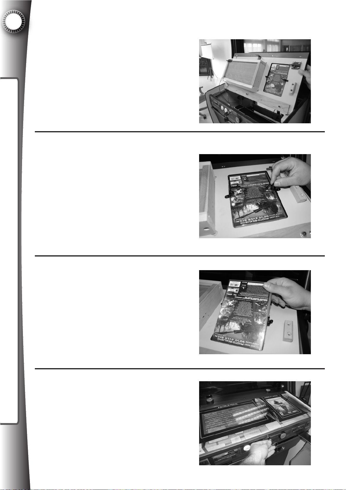
7
Remove the control panel by unlocking the
CUSTOMIZING CABINET APPEARANCE
control panel pin lock. Lift up on the panel.
1
Set the control panel on its top to gain ac-
2
cess to the underside of the panel. Loosen
the two set screws. Pry the existing game
case out of the control panel.
7.2 Changing The Retail Game Case
Fig. 7.2A
3
4
Fig. 7.2B
Insert the new retail game case and tighten
the set screws.
Fig. 7.2C
Replace and lock the control panel.
76
Fig. 7.2D
Page 85
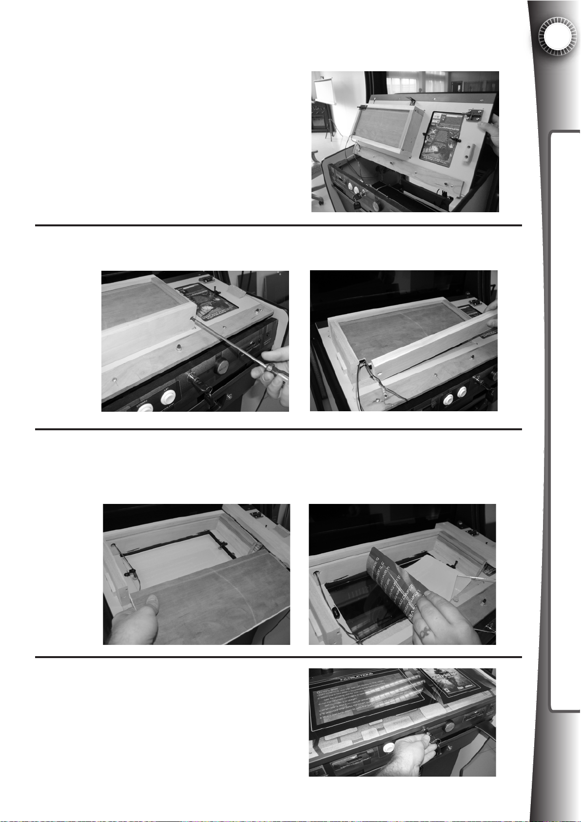
1
2
7.3 Changing The Instruction Panel
Remove the control panel vy unlocking the
control panel pin lock. Lift up on the panel
and set it on its top.
Fig. 7.3A
Use a screwdriver to remove the two screws as shown. Remove the wood panel.
7
CUSTOMIZING CABINET APPEARANCE
Fig.
7.3B
3
.
Fig.
7.3C
Slide the light panel out to move it out of the way. Loosen the set screws and turn out
of the way. Pry the acrylic panel up with a at head screw driver to access/change the
graphic.
Reverse the steps and replace and lock
4
the control panel with the new graphics.
Fig. 7.3D
77
Page 86

7
The Game Gate™ VU side decals are designed to be covered by alternative graphic panels.
Replacement graphic panels are printed on rigid PVC with mounting holes. See the instructions included with the graphic panel set for details on how to change the side panels (screws
included in side panel kits).
CUSTOMIZING CABINET APPEARANCE
7.4 Changing The Side Panels
78
Page 87
8. CARE & MAINTENANCE
Game Gate™ VU should be kept clean and functional at all times. Damaged or broken components should be repaired or replaced as soon as possible.
Cabinet - To clean the cabinet, avoid using any harsh or abrasive chemicals. Wipe the cabinet frequently with a soft cloth. Do not use ammonia based cleaners as this may damage the
polycarbonate lamination.
Controller - If a handheld controller is not functioning, replace it with a new controller as soon
as possible. Replacement controllers are inexpensive and easily found at your local electronics retailer.
Components - If a critical component to the Game Gate™ VU is damaged and the unit is not
functioning properly, contact your distributor or Quasimoto for technical support and warranty/
replacement parts. See the parts list at the end of this manual for part numbers and further
details.
8
CARE & MAINTENANCE
79
Page 88
9
LICENSING INFORMATION
9. LICENSING INFORMATION
Game Gate™ VU allows the use of a video game system and software in a public environment. However, not all publishers and not all games are authorized to use with the equipment. Game titles and publishers available are detailed in the registration server (login to
your account for details), and your distributor will also be able to provide you with a list. New
games are always being released to market, so check frequently to see what new games/licenses have been obtained.
To legally operate Game Gate™ VU (and activate equipment) you must have the following:
1) Valid email address
2) Computer with internet access
3) License paperwork provided by your distributor
4) Valid mailing address
Game Gate™ VU is licensed to operate through our partner iGames, Inc. Game Gate™ VU
includes membership and activation of the equipment. Your distributor will provide you with
license documentation which must be signed by the owner of the equipment. A hardcopy of
this paperwork must be received by mail. The paperwork only needs to be lled out once;
before your rst purchase can be activated. If you have not received this paperwork, please
contact your distributor and request a copy. Fill in all the necessary elds, sign and date two
copies of each agreement and send both copies of the paperwork to this address:
Game Gate™ VU Membership
c/o iGames, Inc.
201 San Antonio Circle suite 260
Mountain View, CA 94040
In return you will receive back one copy of the agreements, signed by iGames, and an invitation letter with membership details. iGames will create an online account for your Game
Gate™ VU management, and will establish a password and login for equipment activation
and renewal (instructions are included). You password and login will be emailed to you and
included in the package.
Make sure to carefully read the agreements. If you have any specic questions about the licenses and limitations, please contact iGames directly by phone or email (contact information
is included in the documentation).
Friendly reminder: You are NOT granted the right to use trademarks and logos without permission from respective owners. For example, you cannot run a promotion, advertisement,
or create a website using any IP that could be perceived as an ofcial endorsement from the
game developer, publisher, or IP holder without consent. If you have any questions about
these limitations, please contact iGames for more information. Quasimoto, iGames, and our
afliates are not responsible for infringement/abuse, as we make no representation that use
of unauthorized IP has been granted. Reported abuse may result in legal actions against you
and your business, as well as termination of your license membership, which includes equipment deactivation.
80
Page 89
10. WARRANTY
Quasimoto is about having fun with video games. We are gamers at heart. It is our objective to
bring the most entertaining and profitable video arcade experience to your best locations We
recognize that this is only possible with the highest quality products, that are superbly designed,
TM
manufactured with the highest quality components to exact specifications, and are built to last.
This is the purpose of our existence as a company. However, try as we might, occasionally prod-
uct is manufactured with defects. In this rare event, we want to make your experience as straight
forward and pleasant as possible.
UASIMOTO HEREBY WARRANTS THAT ITS ARCADE CABINET AND ELECTRONIC COMPO-
NENTS WILL BE FREE FROM DEFECTS IN MATERIALS AND WORKMANSHIP FOR 90 DAYS
WITH THE ORIGINAL OWNER (”oWNER”). QUASIMOTO AGREES, AT ITS SOLE OPTION, WITH NO
CHARGE TO OWNER, TO REPAIR, REPLACE OR REFUND THE COST OF ANY AND ALL PARTS DETER-
MINED TO BE DEFECTIVE, WHETHER IN MATERIAL OR WORKMANSHIP, BY QUASIMOTO. OWNER
AGREES TO PRE-PAY ONe-WAY SHIPPING. QUASIMOTO AGREES TO PAY ONe-WAY SHIPPING.
REPLACEMENT OF THE ENTIRE CABINET OR ITS MAJOR SUB-COMPONENTS IS NOT REQUIRED
UNDER THIS WARRANTY. TO oBTAIN PERFORMANCE OF ANY OBLIGATION OF THIS LIMITED
WARRANTY (”WARRANTY”), THE OWNER MUST CONTACT QUASIMOTO OR AN AUTHORIZED
DISTIRBUTOR. PROOF OF PURCHASE IS REQUIRED.
10
WARRANTY
this warranty is subject to the limitation set forth below:
1. normal and reasonable wear and tear
2. defects or damage due to accident, alteration, abuse, misuse, dropping, natural disaster, neglect, or
failure to provide reasonable and necessary maintenence.
3. cabinet, monitors, electronics, audio systems that have been repaired or installed by parties other than
those authorized by quasimoto.
4. damages exceeding the original cost of the arcade system.
5. warranty does not cover the video game system
in no case shall quasimoto be liable for any special, incidental or consequential
damages for breach of warranty or any implied warranty. some states do not
allow the exclusion of incidental or consequential damages, so the limitation
may not apply to you. this warranty gives you specific legal rights and you may also
have other rights which vary from state to state.
or
TM
Mail: Quasimoto Interactive, Inc.
471 E. Bergey St. Suite 1
Wadsworth, OH 44281
To obtain warranty/technical support, please contact Quasimoto via any of the following methods:
Telephone: 1.888.400.5774
If calling from outside the U.S: 001-330-331-4515
Web: www.quasimoto.com
E-mail: [email protected]
Hours of operation are Monday through Friday, from 9 AM to 5 PM EST, excluding major holidays.
Our technical support staff will do its best to respond to you within 24 hours.
XBox 360® is a registered trademarks of Microsoft Corportation. PlayStation® is a registered trademark of SCEI and/or its affiliates.
Quasimoto™ and Game Gate™ VU are registered trademarks of Quasimoto Interactive, Inc.
81
Page 90
11
20 9 923 1 Pus h w ar n ing s tick e r
11. PARTS LIST
PARTS LIST
Quasimoto
Part #
20 9 101 1 Xb o x w ired c o ntro lle r h o us ing , 2 pa rt to p a n d b o tto m
20 9 102 1 Xb o x w irele ss c o ntro lle r ho u sin g, 2 p a rt to p a n d b ottom
20 9 103 1 AB S sliding co ntro lle r block , 3 pa rt: c o re to p, b o tto m , plu g a nd 3 scre w
20 9 104 1 M e m o ry s o cke t w ith US B B m ale e n d
20 9 105 1 Acrylic ga m e co n so le w ind ow
20 9 106 1 Spe a ke r g r ills
20 9 109 1 Te m pere d g las s c o ntro l pa n el
20 9 107 1 Pla ys ta tio n c on tro lle r h o usin g, 2 p a r
Plastic/
Custom Components
20 9 108 1 Te m pere d g las s m onito r b e ze l
20 9 109 1 Ru b ber c ontroller bra c ket w ith m eta l c or e
20 9 110 1 W hite ac rylic s trip for le f t an d rig ht size LE D ligh t co v er
20 9 111 1 W hite ac rylic s trip for co n so le bra c ket
20 9 112 1 Cle ar a cr ylic s h eet fo r in struc tio n b ac klig h t are a of co n trol p an el
20 9 113 1 Cle ar a cr ylic s h eet fo r b a cklig h t m arq u ee
20 9 114 1 Pla stic trim fo r ba c kligh t m ar q ue e g ra p hic
20 9 115 1 W oo d
sid e p an el c on nec tio n b ars to se c ure top to bo ttom o f ca bin e t
Description
t w ith se c urity s c re ws
20 9 902 1 Ga m e G ate co lor d eca l s et, sid e p ane ls
20 9 903 1 Ga m e G ate m ar q uee g ra p hic
20 9 904 1 Bac k lit in struc tio n g ra p hic , E N GL IS H
20 9 905 1 Volta ge wa r n ing s tic ker
20 9 906 1 Co n trol p an el g ra p hic
20 9 907 1 Ca s ter w a rn in g stic ker
20 9 908 1 Co m plian ce s tic ker (" s er ial d eca l s am ple")
20 9 909 1 M e m o ry c a rd s tick e rs to co v er m eta l p ane ls
20 9 910 1 "R ese t" S tic k er fo r yello w
Printed Artwork
Cables
20 9 911 1 "1 P layer G am e" Stic ker f o r yello w butto n w ith lig ht
20 9 912 1 "2 P layer G am e" Stic ker f o r yello w butto n w ith lig ht
20 9 913 1 He a dph o ne pan e l d eca l
20 9 914 1 Us e r pa n el de c al
20 9 500 1 W ire less co n tro lle r c a ble s , s ho r t
20 9 500 2 W ire less co n tro lle r c a ble , lo n g
20 9 501 1 Xb o x A V C a ble
20 9 502 1 PS 3 A V C a ble
20 9 503 1 M e m o ry s o cke t ca b le, U SB typ e B fe m ale
20 9 504 1 RM T A V c a ble
20 9 505 1 LC D A V cab le
20 9 506 1 RM T c om m un ica tio n c able
20 9 507 1 low er D C w ire h a rn es s
20 9 508 1 upp e r D C w ire ha r n ess
20 9 509 1 m ain c o lor L ED ca b le
20 9 510 1 M a in po w er co r d U SA s tyle 6'
20 9 514 1 He a dph o ne ja c k a ssem bly
20 9 515 1 16 pin h a rn e ss
09 5 161 L ED m atrix c a ble lo we r
2
20 9 517 1 LED m atrix c a ble u p per
20 9 518 1 Xb o x 3 6 0 U SB c a ble , T yp e B m ale, T ype A m ale
20 9 519 1 Eth erne t ca b le, g am e co n sole to R MT
20 9 520 1 Eth erne t ca b le, R MT to ba c k p ane l
bu tton w ith ligh t
82
Page 91
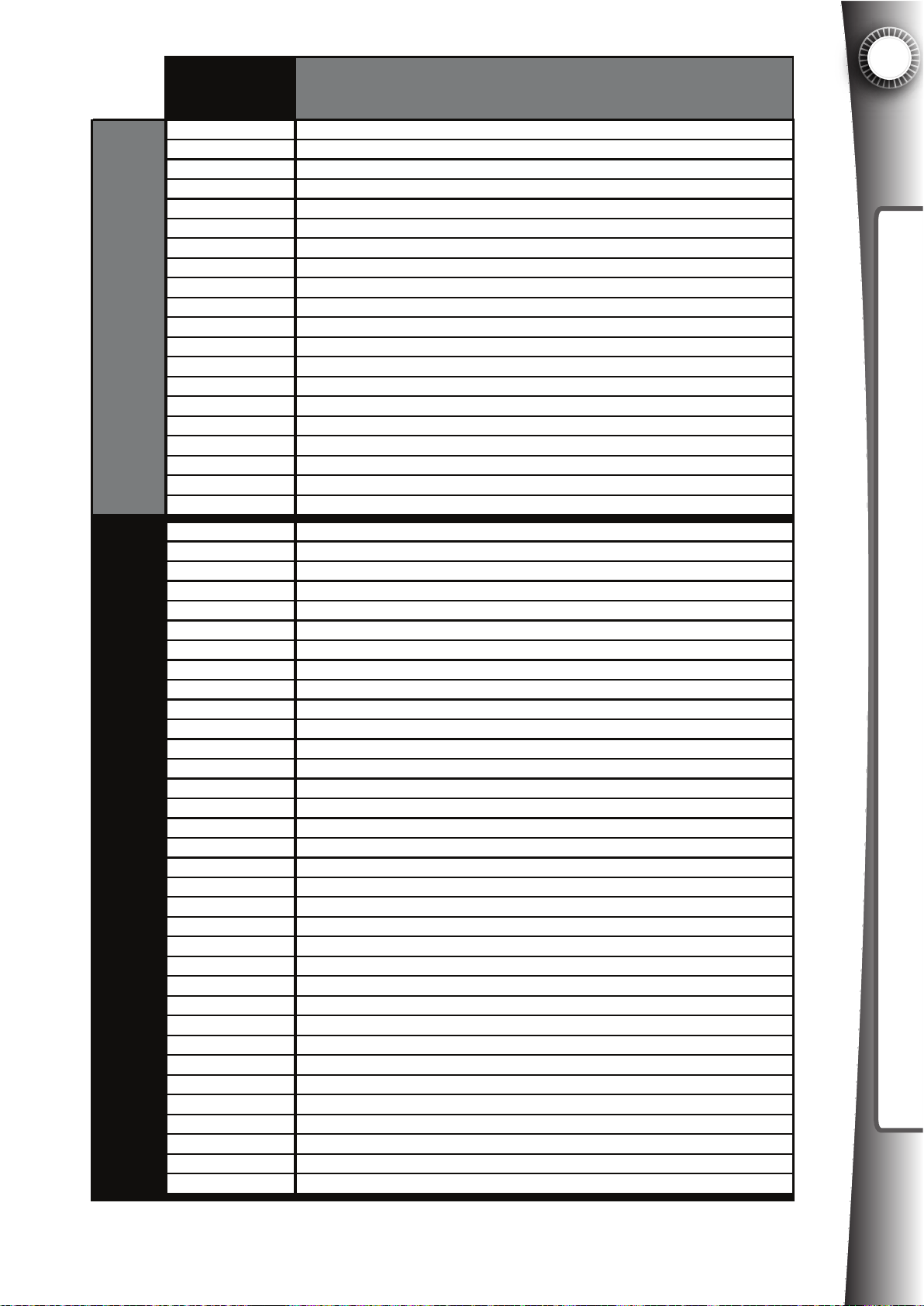
11
Quasimoto
Part #
20 9 5 21 1 A u x cable w ith m et a l p an e l
20 9 5 22 1 H e ad p h on e co nn e ctor c a ble , le ft p layer
20 9 5 23 1 H e ad p h on e co nn e ctor c a ble , rig ht pla yer
20 9 5 24 1 U s er p an e l to R MT U SB cable , p a ne l m oun t
20 9 5 27 1 P u s hb u t ton c a b le to U se r P an e l
20 9 5 28 1 C o in m ete r c a b le
20 9 5 29 1 P a y m ent c a ble
20 9 5 31 1 G ro u n d H a rn e s s - C as te r to A ux , C as ter to P a ne l
20 9 5 32 1 G ro u n d H a rn e s s - B o tto m C ab in e t
20 9 5 33 1 G ro u n d H a rn e s s - U se r P a
20 9 5 34 1 G ro u n d H a rn e s s - B u s to P a n el
20 9 5 35 1 G ro u n d H a rn e s s - C on trol P a ne l
Cables (cont.)Electronic Parts, Electronic Assemblies
20 9 5 36 1 G ro u n d H a rn e s s - U pp e r to L ow er
20 9 5 37 1 G ro u n d H a rn e s s - M arq u ee , C on trol
20 9 5 48 1 G ro u n d H a rn e s s - P o we r b o x cab le
20 9 5 49 1 A C pow er b ox ca b le
20 9 5 50 1 ID E rib bo n ca b le - R MT to com pact fla sh rea d e r
20 9 5 51 1 LC D p o wer c o rd, 3 p r o n g U S A s tyle
20 9 5 52 1 G ro u n d H a rn e s s - B u s to M ar q u ee
20 9 5 53 1 S p e ak e r C on n ec t C ab le
Description
PARTS LIST
ne l
20 9 7 00 1 P rim ary A TX sw it
20 9 7 01 1 T im er b o ard P C B
20 9 7 02 1 R M T w ith A MD pro ce s s or a nd m em ory p r e in s ta lle d
20 9 7 03 1 P S 3 po w er m od u le
20 9 7 04 1 32 " LC D
20 9 7 05 1 LE D m atrix b o ard
20 9 7 06 1 S u b wo of e r , in c lud e s D C tra ns fo rm er a n d vo lum e c o ntro l system
20 9 7 07 1 S p e ak e r
20 9 7 08 1 4G B c o m pa c t fla s h card
20 9 7 13 1 Illu m in a ted pus h b utto n, ye llo w
20 9 7 14 1 H e ad p h on e vo lum e con trol b u tto n
20 9 7 15 1 IE C filte r
20 9 7 16 1 Is olatio n tran s f o r m er
20 9 7 17 1 M ultic ou n t r
20 9 7 19 1 92 m m fa n and co n n ec to r
20 9 7 21 1 P S 2 to P S3 a d ap ter
20 9 7 22 1 M arqu e e L E D a s s em bly
20 9 7 23 1 Le ft p a ne l L ED ass e m b ly
20 9 7 24 1 R igh t pan e l LE D a s s em bly
20 9 7 25 1 C o ntro l pa n el L E D a s se m b ly
20 9 7 26 1 C o ns o le LE D a s s em bly
20 9 7 27 1 C o in m ete r
20 9 7 28 1 U S A p o wer s t rip with m ale IE C c o nn e c tor, 12 " cab le
20 9 7 29 1 ID E to C F ada p ter
20 9 7 30 1 C o in d o or to p w it
20 9 7 31 1 C o in d o or w ith center p os ition slo t, m etal b o x, a n d pla stic bo x
20 9 7 32 1 D D R2 51 2 m b m em ory , SO DIM M 20 0 p in
20 9 7 33 1 A M D A thlo n 164 0 2.8G Hz 1 m B L2 C a ch e
20 9 7 35 1 M SI F uz zy 6 90 T
20 9 7 36 1 S o u nd s ystem p o w er su p p ly tra n s form er
20 9 7 37 1 R e d pu s h bu tto n fo r U se r P a ne l
20 9 7 38 1 IE C o u tle t
20 9 7 39 1 1G B U SB flash d riv e
20 9 7 40 1 LC D re m ote c o ntro l
chin g po w er s up p ly
y p o w er strip w ith m a le IE C con n ec tor, 1 2 " c a ble
h b ill valid a to r slo t
83
Page 92
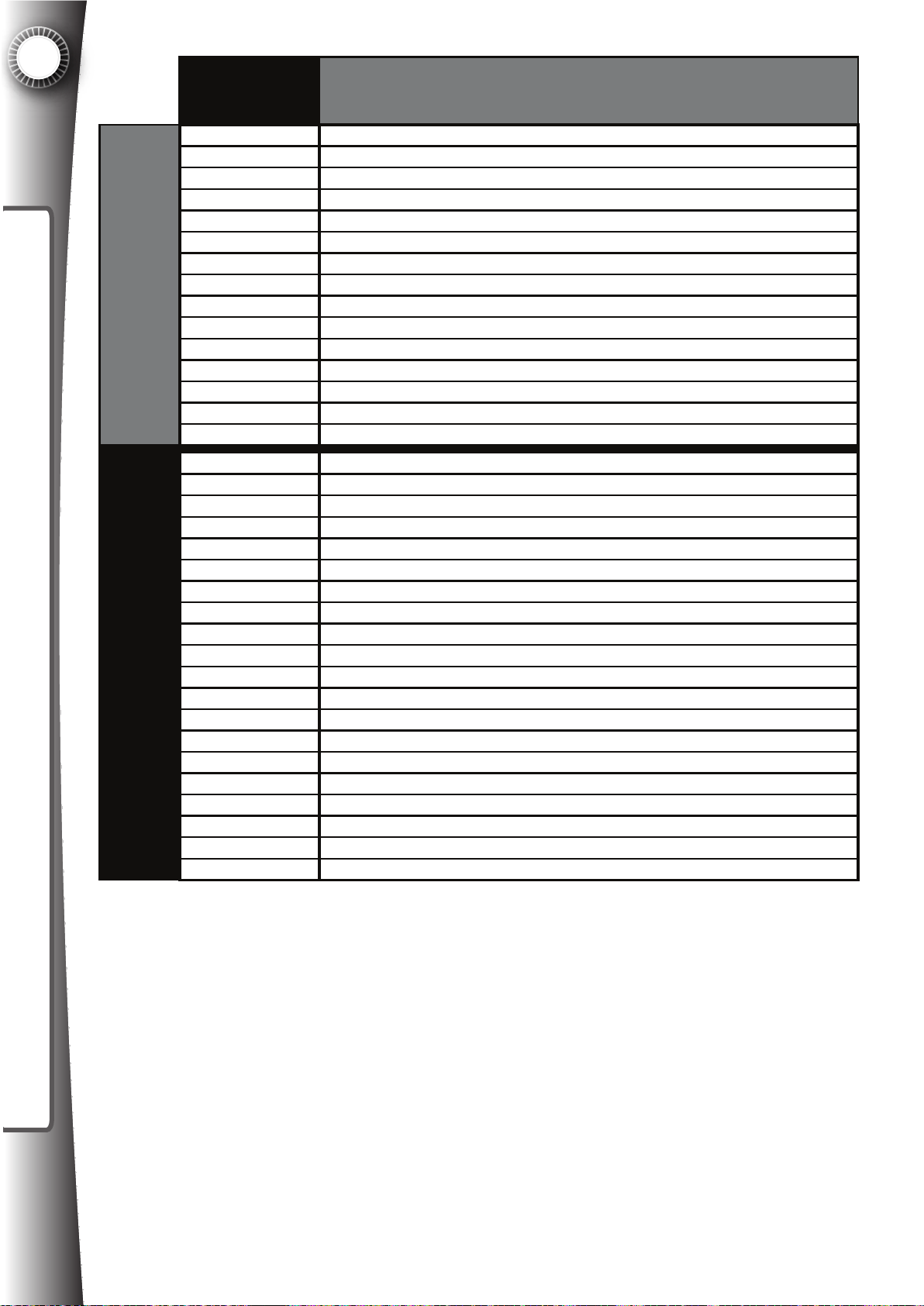
11
20 9 420 1 U-B olts
PARTS LIST
Quasimoto
Part #
20 9 300 1 M e ta l b ra ck et f o r ca s te rs
20 9 301 1 M e ta l d oor fr o nt a s se m bly with s lid ing b ra c ket system
20 9 302 1 G las s c lip , f ro nt pa n el
20 9 303 1 G las s c lip , b ac k pan e l
20 9 304 1 M e ta l g ro un din g bloc k
20 9 305 1 Xb o x 3 60 po w er su p ply brac k et with rub b er
20 9 306 1 M e ta l A C p ow e r bo x
20 9 307 1 Tre a d P late
20 9 308 1 M a rq u ee B ra c ket
20 9 310 1 Pa n el C o ver 1 w ith 3 ho les
Metal ComponentsHardware
20 9 311 1 Pa n el C o ver 2 w ith 2 ho les
20 9 312 1 Prim ary p
20 9 313 1 M e ta l L b r a ck et f o r co n tro l p ane l
20 9 314 1 Alu m inu m L ch a nn e l f o r m ou nting s id e co lo r LE Ds
20 9 315 1 M e ta l L b r a ck et f o r slid ing bra c ket, a ttac h es to s lid ing b loc k
20 9 400 1 Fa n fin g er gu a rd
20 9 401 1 RJ 4 5 c onn e cto r
20 9 402 1 Leg leve le r
20 9 403 1 Ca s te r s
20 9 404 1 Loc k 1, p u sh pin type
20 9 405 1 Loc k 2, p u sh pin type k e y dif fe r e nt
20 9 406 1 Loc k 3, w ood d o or loc k
20 9 411 1 Se c ur ity s c re w driver
11 1 Ca bin e t h inge , eu ro style , 2 pa r ts top a n b o ttom
20 9 4
20 9 412 1 Co n tro l p ane l la tch
20 9 413 1 Dra w er ca tc h for hing e d p an el, 2 p iec e
20 9 414 1 Bla ck he x b o lt fo r ca b ine t a s sem bly, s h ort
20 9 415 1 Bla ck he x b o lt fo r ca b ine t a s sem bly, lon g
20 9 416 1 Bla ck w a she r for ca b ine t as s em bly b o lts
20 9 417 1 Th u m bscre w s for ho lding g a m e c as e a nd grap hic
20 9 418 1 Bla ck w a she r for ca b ine t as s em bly b o lts
20 9 417 1 Th u m bscre w s for ho lding g a m e c
20 9 418 1 Bla ck w a she r for ca b ine t as s em bly b o lts
20 9 419 1 Ru b be r b u m pe r s tic ker f o r co n tro l p ane l g rap h ic
ow er s u pply b ra c ket with rub b er
Description
as e an d g r a phic
84
Page 93
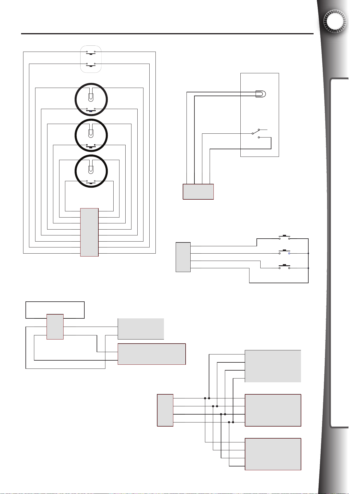
12. WIRE DIAGRAMS
12.1 Wire Diagrams
Volume Down
Volume Up
Player 1
Player 2
12
WIRE DIAGRAMS
Coin
Mech
Yellow
J25
4
Mini
Fit Jr
5
6
Mini Fit Jr - 6 pin
Reset
Black
Yellow
Black
Yellow
Black
Yellow
Red
Black
J12
9
10
11
12
Mini
Fit Jr
13
14
15
16
Mini Fit Jr - 16 pin
1
2
Blue/White
3
Orange/Black
4
Orange/White
5
Gray/Black
Gray/White
6
7
Red/White
8
Black/White
Bl ue/Black
16 PIN HARNESS
PART #2095151
1
2
Brown/Yellow
3
Green/Yellow
Credit Mech
Counter
Y ellow
B lack
W hi te/ Black
1
2
3
F it J r
M ini
J17
Molex Mini-Fit Jr 4 pin
J3
1
2
Mi ni
Fit Jr
3
4
Molex Mini-Fit Jr 4 pin
USER PANEL
PART #2095271
PAYMENT CABLE
B lack
PART #2095291
4
Green/White
Brown/White
Yellow/White
Black
User Mode
Soft Reset
Free Coin
Black
Black
COIN METER CABLE
PART #2095281
Free Credit Mech
Counter - not installed
J13
1
2
Mi ni
Fi t Jr
3
4
Molex Mini-Fit Jr 4 pin
LED LIGHT CABLE
PART #2095091
Yellow
Red/Black
Green/Black
Blue/Black
Common
Red
Green
Blue
Common
Red
Green
Blue
Common
Red
Green
Blue
Left Side
LED Modules
Console
LED Modules
Right Side
LED Modules
85
Page 94
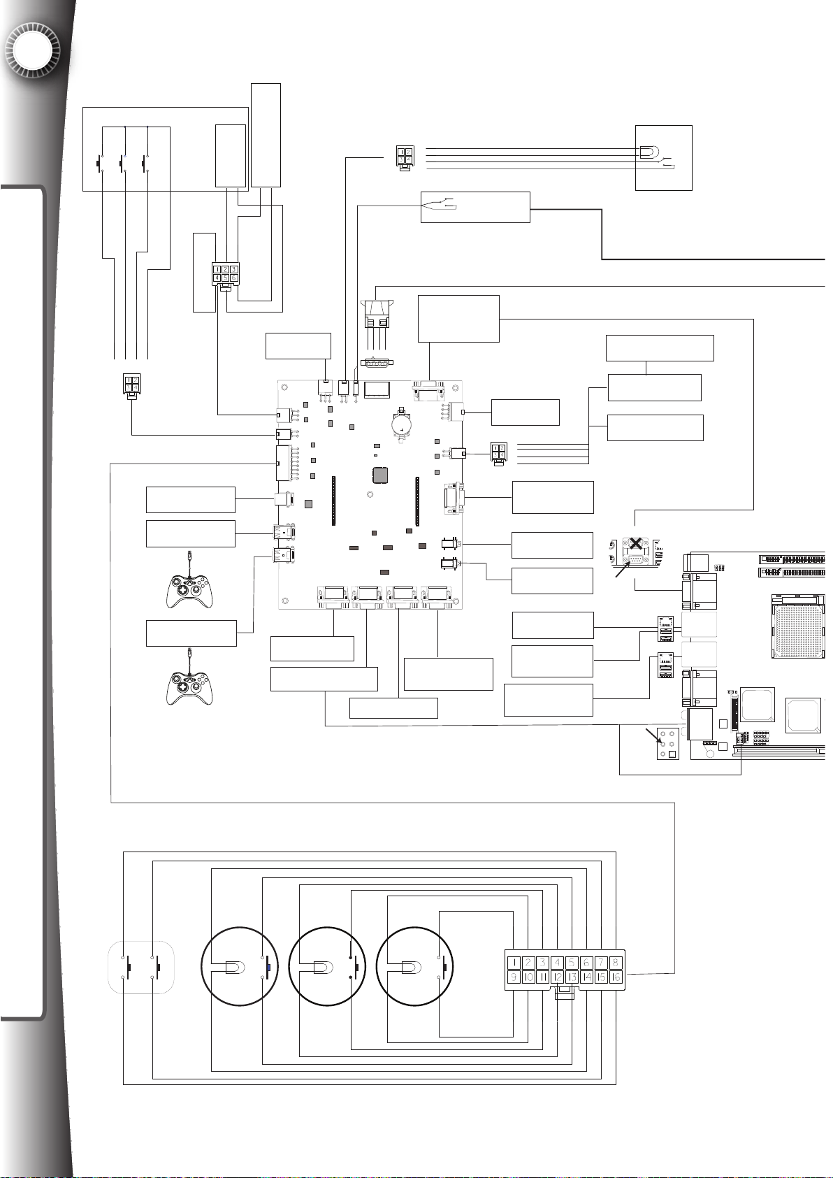
12
SAT
METAL BOX #2093091
Free Coin
User Reset
User Mode
WIRE DIAGRAMS
Brown/White
Black
Green/White
Yellow/White
#2095271 GAUGE 20B
1
4
2
3
TO GAME CONSOLE
USB PORT
#2095181
TO GAME
CONTROLLER 1
TO GAME
CONTROLLER 2
Yellow
1
Black
2
White/Black
3
Black
FREE CREDIT COIN
COUNTER
COIN METER
Brown/Yellow
123
Yellow
J25
4
5
Green/Yellow
6
METER - NOT INSTALLED
Black
Black
#2095281 GAUGE 20B
OPTIONAL
J10
J25
J3
J12
J9
J8
J10
TO GAME CONSOLE
AV PORT
#2095001
TO RMT AUDIO/
VIDEO PORT
#2095041
Red
Black
Black
4 3 2 1
J17 J16
P14 P5
TO AUX OUT PANEL
#2095211
4
TO RMT SERIAL
#2095061
Yellow
P6 J7
J19J20J21J22
TO LCD VIDEO INPUT
AND AMPLIFIER
#2095051
PORT RS232
(BOTTOM)
J4
J13
J15
J27
J26
#2095291 GAUGE 20B
BILL VALIDATOR
(OPTIONAL)
OPTIONAL
1
2
3
4
#2095241
#2095201
TO GAME CONSOLE
#2095191
Yellow
Red
Green
Blue
#2095091 GAUGE20B
LED MATRIX DB9
HEADER
#2095171 AND #2095161
TO 3.5MM STEREO
HEADPHONE P1
TO 3.5MM STEREO
HEADPHONE P2
TO USER PANEL
USB X 2
TO AUX PANEL
RJ45 OUTPUT
RJ45 INPUT
12V LAMP
COIN MECH
COLOR LED CONSOLE
BAR X2 SET
COLOR LED LEFT
PANEL X6 SET
COLOR LED RIGHT
PANEL X6 SET
Top: Lan Jack
Bottom: USB Ports
Top: Lan Jack
Bottom: USB Ports
Top: mouse
Bottom:
keyboard
COM Ports
Top: VGA Port
Bottom: HDMI
T: Line-In/ SS Out
M: Line-Out
B: Mic
T: RS - Out
M: CS- Out
B: SPDIF Out
JAUD1
J2
J1
SOCKET AM2
J3
AMD
RS690T
ALC888
JTV1
21
SB600
JUSB2
JUSB1
86
Volume Down
#2095151 GAUGE 20B
B lue/Black
Gray/White
Orange/Black
Orange/White
3
4
11
12
Black
Yellow
Gray/Black
5
13
Black
Blue/White
2
1
Volume Up
Player 1
Player 2
Reset
9
10
Black
Yellow
678
141516
Yellow
Red Red/White
Black/White
Black
Page 95
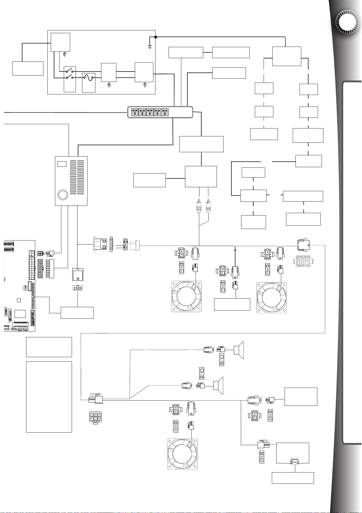
#2095101AC POWER CORD
WALL OUTLET
100-240VAC
IEC INLET
L N
G
DPST
#2097001 GAUGE20
I/O
POWER SUPPLY
6 AMP
FUSE
METAL BOX #2093061
FILTER
#2095551AC POWER CORD
#2095491 GAUGE14
#2095531AC POWER CORD
IEC
OUTLET
VOLUME/BASS
REMOTE
GAME CONSOLE
POWER SUPPLY
#2095511AC POWER CORD
#2095541AC POWER CORD
POWER
STRIP
AC/DC TRANSFORMER
100-240V - 16VDC 4.5A
SUBWOOFER
GAME CONSOLE
LCD MONITOR
POWER INPUT
CASTER
GROUND
CASTER
GROUND
AUX PANEL
GROUND
MARQUEE
GROUND
#2095361, 2095371
GAUGE 14
GROUNDING
BLOCK
#20955331
GAUGE 14
USER PANEL
GROUND
#20955321
GAUGE 14
#20955321
GAUGE 14
#20955311
GAUGE 14
#20955321
GAUGE 14
GROUND
TERMINAL
ATTACHED TO
POWER BOX
#20955301
GAUGE 14
#20955321
GAUGE 14
CASTER
GROUND
#20955321
GAUGE 14
CASTER
GROUND
#20955321
GAUGE 14
FRONT TREAD
PLATE GROUND
#20955321
GAUGE 14
COIN DOOR
GROUND
SLIDING CONTROL
BRACKET GROUND
#20955371
GAUGE 14
CONTROL PANEL
GROUND
12
WIRE DIAGRAMS
DIMM1
DIMM2
ATA1
SATA2
W83627DHG
JCASE1
JBAT1
JFP1
JPW1
20
10
ATX1
11
1
BATT
J4
#2095501
IDE81
Winbod
JLPT1
CON1
SYSFAN1
CPUFAN1
JPW1
1. BLACK - 18AWG GND
2. BLACK- 18AWG GND
3. YELLOW/BLACK - 18AWG +12V
4. YELLOW BLACK - 18AWG +12V
ATX1
1. ORANGE - 18G +3.3V
2. ORANGE - 18AWG +3.3V
3. BLACK - 18AWG GND
4. RED - 18AWG +5V
5. BLACK - 18AWG GND
6. RED - 18AWG +5V
7. BLACK -18AWG GND
8. GRAY - 22AWG PWK_OK
9. PURPLE - 18AWG 5V_SV
10. YELLOW -18AWG +12V
11. ORANGE -18AWG +3.3V
12. BLUE - 18AWG -12V
13. BLACK -18AWG GND
14. GREEN - 22AWG PS_ON
15. BLACK - 18AWG GND
16. BLACK - 18AWG GND
17. BLACK -18AWG GND
18. NC - 18AWG -5V
19. RED - 18AWG 5V
20. RED - 18AWG 5V
#2097001 GAUGE20
IDE TO CF
READER
Black
Yellow
#2095081 GAUGE20B
#2095071 GAUGE20B
Black
Yellow
LOWER REAR
FAN
Black
Yellow
Black
Yellow
CONTROL PANEL
LED X 4 SET WHITE
POS
GRND
LEFT SPEAKER
POS
GRND
RIGHT SPEAKER
Black
Yellow
GAME CONSOLE
FAN
Black
Yellow
MARQUEE LED
X 10 SET WHITE
GAME CONSOLE
FAN
Black
Yellow
LED MATRIX
TO LED MATRIX
DB9 TIMERBOARD J15
87
Page 96
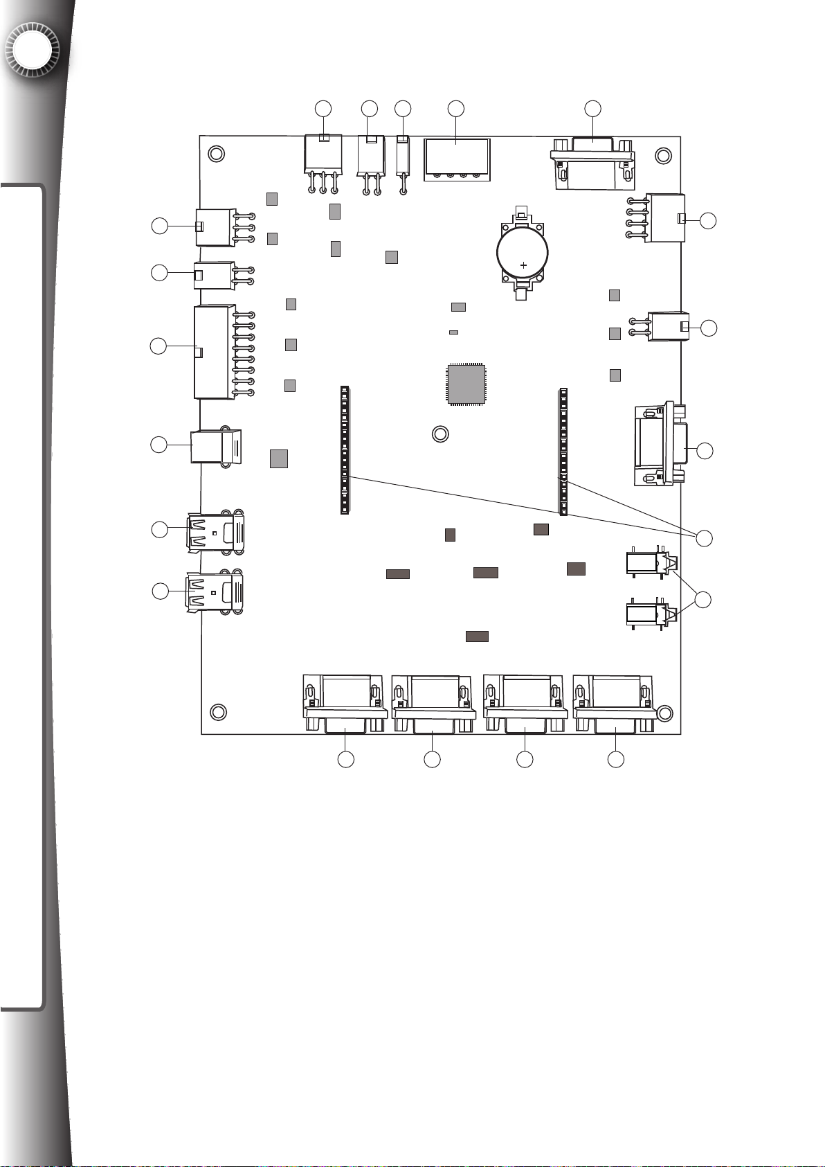
12
12.2 Timerboard
910111213
WIRE DIAGRAMS
14
15
16
17
18
J25
J3
J12
J9
J8
J10
P6 J7
J17 J16
8
J4
7
J13
6
J15
P14 P5
20
19
J10
J19J20J21J22
21 3 4
J27
J26
5
1. Game System AV input - (not VGA) runs component video signals and audio signals from
the game system into the timerboard.
2. RMT AV input - (not VGA) runs component video signals and audio signals from the RMT
into the timerboard.
3. Aux panel output - (not VGA) connects to the component video and audio jacks on the
back of Game Gate for shadow monitor and external amplication.
4. AV output - (not VGA) connects to the component video input on the LCD and the 3.5mm
jack of the powered sound system in the cabinet.
5. Headphone output - connects to the front jacks on the cabinet for headphone connection.
6. LED matrix - connects to the LED matrix at the top of the cabinet.
88
Page 97
7. Color LED - connects to the color LEDs on the cabinet.
8. Expansion 1 - not used in the current application.
9. RS232 - connects to the RMT for data communication via DB9 serial cable.
10. Power - power input for the timerboard.
11. Bill acceptor - connect to a BA for credit pulses.
12. Coin mech/light - connects to the coin meter and light on the coin door, may also be con-
nected to an electronic mech.
13. Expansion 2 - not used in the current application.
14. Coin counters - connected to the coin meter, and also an optional free coin counter can
be added.
15. User panel - connected to the user reset, free coin, and user mode buttons on the user
panel
12
WIRE DIAGRAMS
16. Input connections - 1P, 2P, RESET, volume up, volume down, and lights.
17. USB to console - connects to the Xbox 360® or PLAYSTATION®3 USB port
18. Player 1USB - connects to the left player handheld controller.
19. Player 2 USB - connects to the right player handheld controller.
20. Expansion 3,4 - used for testing purposes, not used with this application.
89
Page 98
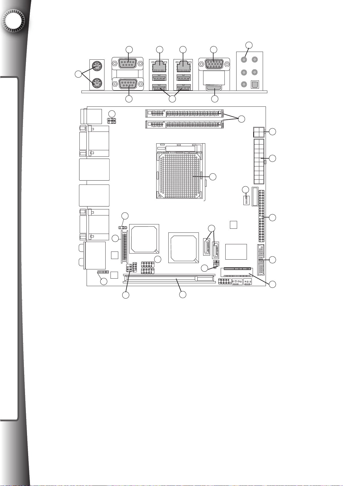
12
12.3 MSI Fuzzy 690T Motherboard (RMT) Diagram
1
WIRE DIAGRAMS
Top: mouse
Bottom:
keyboard
COM Ports
Top: Lan Jack
Bottom: USB Ports
Top: Lan Jack
Bottom: USB Ports
2 4 6
3
23
J2
J1
5
SOCKET AM2
7
8
DIMM1
DIMM2
26
9
10
JPW1
11
ATX1
12
17
BATT
J4
Top: VGA Port
Bottom: HDMI
T: Line-In/ SS Out
M: Line-Out
B: Mic
T: RS - Out
M: CS- Out
B: SPDIF Out
JAUD1
21
20
ALC888
JTV1
19
J3
AMD
RS690T
SB600
25
JUSB2
JUSB1
24
22
SATA1
18
16
SATA2
JBAT1
W83627DHG
JCASE1
JFP1
CPUFAN1 SYSFAN1
Winbod
CON1
IDE81
JLPT1
13
14
15
Fig 12.3
1. Keyboard and mouse - input devices not used with this application
2. DB-9 serial port 1 - not used with this application
3. DB-9 serial port 2 - connects to the timerboard PCB via a DB9 serial cable to relay data
regarding game status
4. RJ45 port 1 - connects via a Cat6 Ethernet cable to the Microsoft Xbox 360 video game
system (optional) for networked gaming purposes
5. USB ports (4) - two ports are connected to an extension cable to extend the ports to
behind the coin door (on the User Panel) which allows the operator (licensed user) to change
system settings through a USB keyboard and/or mouse. The other two USB ports are not
used with this application, unless a USB wireless receiver is added to the equipment (not
included)
6. RJ45 port 2 - connects the RMT to an external internet source (optional via a Cat6 ethernet cable).
90
Page 99
7. VGA Port - a DB15-pin female connector for video output that is not used with this application.
8. HDMI Port - a video output that is not used with this application.
9. Audio in/out - the only connector used with the Game Gate application is the stereo audio
line out (green connector), which outputs the audio to the timerboard. Other connectors, such
as SPDIF are not used.
10. DIMM1, DIMM2 - Game Gate uses one 512mb SO-DIMM 200pin 800mHz memory in
DIMM1 slot. DIMM2 is not used with this application.
11. JPW1 Power input connector
12. ATX1 - 20 pin connector, standard ATX computer power input coding.
13. IDE81- Game Gate™ connects a 4GB compact ash card to the motherboard via an IDE
ribbon cable and an IDE to compact ash converter, which effectively acts as the hard drive
for the machine.
12
WIRE DIAGRAMS
14. JLPT1 - a parallel port, not used with this application.
15. CON1 - Mini PCI-E slot, not used with this application.
16. SATA - Serial ATA connectors used for high speed data rates, designed to connect to
SATA compatible hard disks. Game Gate™ does not use SATA hard drives so these connectors are not used with this application.
17. I2C Bus Connector - used for users that connect SMBus interface, however this is not
used with this application.
18. JCASE1 - Not used with this application.
19. J3 - this jumper is used to specify the operation voltage of the LVDS interfaced at panel,
which is not used with this application.
20. LVDS Flat Panel Connector: JLVDS1 - The LVDS (Low Voltage Differential Signal)
connector provides a digital interface typically used with at panels. This feature is not used
in the Game Gate™ application, rather the component video output is used to achieve video
signal with the 32” LCD in the system.
21. JAUD1 - this is an amplied audio output connector (left spk, left ground, right spk, right
ground) that is not used with this application.
22. PCI (Peripheral Component Interconnect) Slot - supports LAN card, SCSI, USB card, and
other add-on cards that comply with PCI specications, however this connector is not used
with the Game Gate™ application
23. J1,J2 - these jumpers specify th operation voltage of the onboard serial ports, and are not
to be adjusted for the Game Gate application.
24. JTV1, TV-Out Connector - the mainboard output for component video, which is connected to the timerboard for video control, which is then passed to the 32” LCD display.
91
Page 100

12
25. JUSB1,2 - for connecting high-speed USB interface peripherals. These headers are not
used with this application.
6. Socket AM2 - for an AMD processor, Game Gate uses model 1650 2.8GHz 1mB L2
Cache processor for operation.
WIRE DIAGRAMS
92
 Loading...