

Page 1
ENFORCER RF RECEivERs ENFORCER RF RECEivERs
Installation Manual
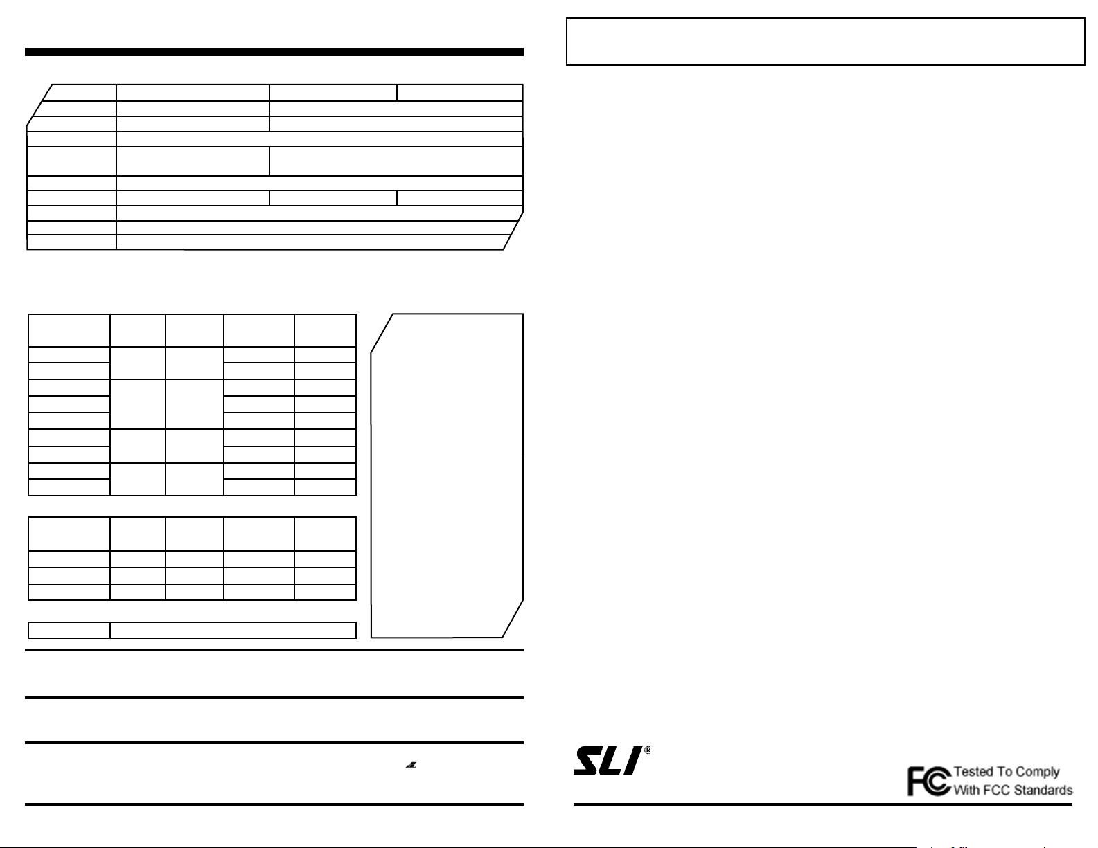
Specifications:
SK-910RAQ
Range
Operating Voltage
Memory Capacity
Current Draw
Output mode
Output type
Dimensions
Frequency
Transmitter
Up to 500’ range
11-24 V AC/DC (16~24 VAC/DC must cut LP4)
15 transmitter button codes per channel
5mA standby, 50mA LED ashing @
12VDC
Programmable 4-sec. momentary (default), 1-sec. momentary, toggle (ON/OFF), or validity
3A Form ‘C’ relay (NO/NC/C).
33/16” x 29/16” x 3/4” (80 x 65 x 19 mm)
315MHz. (Other frequencies available. Please contact SECO-LARM.)
Compatible with all SECO-LARM transmitters
Compatible Transmitters
Fixed-Code: 68 billion codes. CODEBUMP code-hopping: 18 quintillion (1.8 x 10¹⁹) codes
Pendant Remotes
Model Number
SK-919TD1S-U
SK-919TD1S-UP
SK-919TD2A-U
SK-919TD2A-UP
SK-917T2A
SK-919TP3J-N
SK-917T3J
SK-919TP4J-N
SK-917TP4J-N
Hand-Held Remotes
Model Number
SK-919TP1H-B
SK-919TP2H-N
SK-919TP4H-N
Accessories
SK-9HBC
WARRANTY: These ENFORCER RF receivers are warranted against defects in material and workmanship while used in normal
service for a period of one (1) year from the date of sale to the original customer. Our obligation is limited to the repair or replacement of
any defective part if the unit is returned, transportation pre-paid, to SECO-LARM.
Copyright © 2013 SECO-LARM U.S.A., Inc. All rights reserved. This material may not be reproduced or copied, in whole or in part,
without the written permission of SECO-LARM.
The SECO-LARM policy is one of continual development and improvement. For this reason, SECO-LARM reserves the right to change specications without further notice.
# of
Buttons
1
2
3
4
# of
Buttons
1
2
4
# of
Channels
1
3
Code Hopping
7
Code Hopping
15
Code Hopping
# of
Channels
1
3
15
Belt clip holster for hand-held remotes
SECO-LARM® U.S.A., Inc.
16842 Millikan Avenue, Irvine, CA 92606
Tel: 800-662-0800 / 949-261-2999 Fax: 949-261-7326
SK-910RAVQ
Up to 500’ range
5mA standby, 15mA LED ashing @ 12VDC
Transistor GND x 1, 5A @ 12VDC Transistor GND x 2, 3A @ 12VDC
Coding
Fixed
Fixed
Fixed
Fixed
Fixed
Fixed
Blank or
Pre-coded
Blank
Pre-coded
Blank
Pre-coded
Pre-coded
Pre-coded
Pre-coded
Pre-coded
Pre-coded
SK-910RAV2Q
3-13.8 VDC
CODEBUMP
With SECO-LARM’s
CODEBUMP, so-called
code-grabbers and scanners are rendered obsolete
because the RF code changes
every time the transmitter
button is pressed. In addition,
with over 18 quintillion (1.8
x 1019) codes, the chances
of ever repeating a code are
virtually non-existent.
Coding
Fixed
Fixed
Fixed
Blank or
Pre-coded
Pre-coded
Pre-coded
Pre-coded
SECO-LARM’s CODEBUMP
transmitters and receivers
are perfect for controlling
garage and gate openers,
car and home alarms,
plus much more.
FILE: D\DTP\Manual\Mi-SK-910RAxxQ_051013.indd
®
PITSW1
Order Part #762-107-3%
Website: www.seco-larm.com
E-mail: sales
@
seco-larm.com
Page 4
ENFORCER
SK-910RAQ SERIES
Miniature RF
Receivers
l
Up to 500 ft. range
l
Operate on 11-24VAC/DC
l
Code learning
l
FCC compliant
l
Fixed code or CODEBUMP code-hopping
Introduction
These mini RF receivers are compatible with both code hopping and xed-code transmitters (see page 4 of this manual
for a list of compatible transmitters). They can be used for a variety of applications, such as allowing the same transmitter to
arm/disarm a vehicle alarm and open/close a garage door opener. The receivers come in one- or two-channel versions.
Each channel can learn the codes of up to 15 different transmitter buttons on a rst-in, rst-out basis.
Installation Notes
1. Mount out of sight in a location where it is not surrounded by metal, and where it is not exposed to the weather or
moisture. Metal will block the RF signal, resulting in a reduced range.
2. For best range, pull the antenna wire as straight and high as possible. If the receiver receives interference from local
RF activity (eg., airport or military base), the antenna wire can be folded. DO NOT CUT THE ANTENNA WIRE.
Models Available
SK-910RAQ ............1-channel mini-receiver, 3A Form “C” relay, 315MHz
SK-910RAVQ .........1-channel mini-receiver, 5A transistor ground output, 315MHz
SK-910RAV2Q .......2-channel mini-receiver, 3A transistor ground outputs, 315MHz
SK-910RA-4Q ........1-channel mini-receiver, 3A Form “C” relay, 433.92MHz
SK-910RAV-4Q ......1-channel mini-receiver, 5A transistor ground output, 433.92MHz
SK-910RAV2-4Q . ..2-channel mini-receiver, 3A transistor ground outputs, 433.92MHz
More RF receivers are available (1 to 4 channels). Contact SECO-LARM for details.
1
All models work on 11-24VAC/DC, except for the low voltage versions.
SECO-LARM
Note: Products with model numbers that end with “Q” or that have a round green”Q”sticker are RoHS compliant.
®
1
®
SK-910RAQ
Shown
Page 2
ENFORCER RF RECEivERs ENFORCER RF RECEivERs
Learning a New Button Code (channel 1)
1. Press the mode switch which is located at the top of the receiver case for three seconds. The green LED will start to
ash quickly.
2. While the green LED is ashing quickly, press a button on a compatible transmitter. The green LED will ash once
and then turn off to show that button was learned.
3. Repeat steps 1 and 2 to learn more buttons into channel 1.
NOTE — The green LED will ash a maximum of 15 seconds. If no transmitter button is pressed during this time, the
receiver will exit the code-learning mode, and the green LED will turn off.
Learning a New Button Code (channel 2, SK-910RAV2Q only)
The procedure is the same as for channel 1, except mode switch #2 (black switch) initiates the code-learning process,
and the red LED shows status. For two channel receivers, red color push-button represent mode switch #1 and black
color push-button represent mode switch #2 .
Note Regarding Code Learning
1. The receiver will only learn the code of a particular button once. Once a button’s code is learned, if you try to codelearn that button again, whether it is for the same channel or not, the receiver will remain in the code learning mode.
The LED will turn steady ON (1-sec.) to show the code is already in memory.
2. Each channel can learn the codes of a maximum of 15 transmitter buttons. If you attempt to learn a sixteenth button,
the earliest code learned will be deleted and replaced by the new code (rst-in, rst out).
3. To clear all codes — To clear all codes in the channel’s memory, press the appropriate mode switch (#1 or #2)
for three seconds. When the LED starts ashing, press that switch again for three seconds. The LED ashes twice to
indicate that all codes associated with that channel are now deleted.
Programming Output Modes (see table 1)
4-second momentary
1-second momentary
Toggle
Validity
Press the transmitter button once. The output turns on for 4 seconds, and then turns off.
(This is the DEFAULT mode)
Press the transmitter button once. The output turns on for 1 second, and then turns off.
Press the transmitter button once, and the output turns on. Press a compatible transmitter
button again, and the output turns off.
The relay turns on for as long as the transmitter button is pressed.
Mode Switch Operation (one per channel)
Learn mode
Clear memory
Memory Display
Press and hold the switch for three seconds. The appropriate LED will ash quickly to show that it
is ready to learn a transmitter code.
Press three seconds, then when the appropriate LED starts ashing, press again for three seconds
to delete all previously learned codes. The LED will ash twice to conrm codes deleted.
Press and immediately release the mode switch to show number of codes stored. The appropriate
LED will ash a number of times to correspond to the number of codes stored.
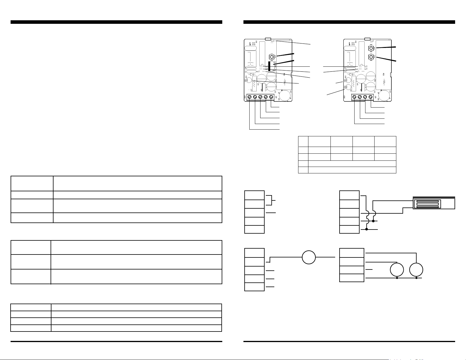
SK-910RAQ
Mode switch #1
Ext. range antenna connector
Channel 1 Status LED
(SK-910RAV2Q only)
11~24 VAC/VDC
{
No polarity
COM
NO
NC
Table 1: To program outputs,
open case and nd the jumpers marked LP1, LP2, LP3,
and LP4 . Cut these jumpers,
if needed, as follows:
Typical Applications:
Positive or negative output:
NC
NO
COM
+
12VDC receiver power input,
24VAC output driving a motor
NC
NO
COM
+
Positive or Negative Power
Output (Choose NO or NC)
Positive or Negative
Power Source
Power for SK-910RAQ /
}
SK-910RA-4Q
24VAC(1) Output
24VAC(1) Input
GND
+12VDC
LP1
LP2
LP3
LP4
Motor
SK-910RAVQ/RAV2Q
Loop 3
Loop 2
Loop 1
Loop 4
Channel 2
Status LED
3~13.8 VDC
GND
Ch 1 transistor ground
Ch 2 transistor ground
(SK-910RAV2Q only)
4-SEC.
MOMENTARY
UNCUT UNCUT CUT CUT
UNCUT CUT UNCUT CUT
CUT LP3 TO USE EXTERNAL ANTENNA
CUT LP4 FOR 16~24VAC/DC POWER INPUT (for SK-910RAQ only)
24VAC(2)
1-SEC.
MOMENTARY
12VDC receiver power driving a 12VDC appliance
TOGGLE
(for SK-910RAQ only)
VALIDITY
NC
NO
COM
+
For SK-910RAVQ /SK-910RAV-4Q and
SK-910RAV2Q / SK-910RAV2-4Q
CH 2 Output**
CH 1 Output*
-
12VDC O/P
GND
+12VDC
GND
+
* For SK-910RAVQ / SK-910RAV-4Q
** For SK-910RAV2Q / SK-910RAV2-4Q
Mode switch #2
(SK-910RAV2Q only)
Mode switch #1
NOTE — For the SK-910RAV2Q
2-channel model, the mode of
both outputs is the same. In
other words, you cannot have
4-second momentary output for
channel 1 and a validity output
for channel 2.
(-)
(+)
Electromagnetic lock
Power for SK-910RAQ /
}
SK-910RA-4Q
DEVICE #1DEVICE
#2
+3~13.8VDC
LED Indication (one per channel)
Steady on
Fast ash
One ash
Two ashes
Senses signal from a transmitter button whose code was already learned.
In the code-learning mode.
A transmitter button code was learned.
All previously learned transmitter button codes were deleted.
Page 2
Extended Range Antenna for SK-910RAQ only
The optional SK-91ERSD extends the RF receiver range to up to 1,200’ (open air) with existing remotes.
The antenna comes with a 9’ cable which easily plugs into the 3-pin antenna port located on the RF receiver motherboard
(see the illustration above).
IMPORTANT:
SK-910RAQ, the receiver PC board loop marked “LP3” must be cut.
Page 3
If an extended range antenna is used with the
SK-91ERSD
 Loading...