


Service Manual
7551021004
01.10.2006
Variants:
7551021994
7551321004
7551321994
7567021004
7567021994
for seca
Description:
Mechanical Dial scale with BMI function
755 CN / 756 CN
Content:
Operation mod. 755 17-10-06-308 a
Operation mod. 756 17-10-07-508 a
Service Manual Number
17-05-01-327- a
Valid as of:
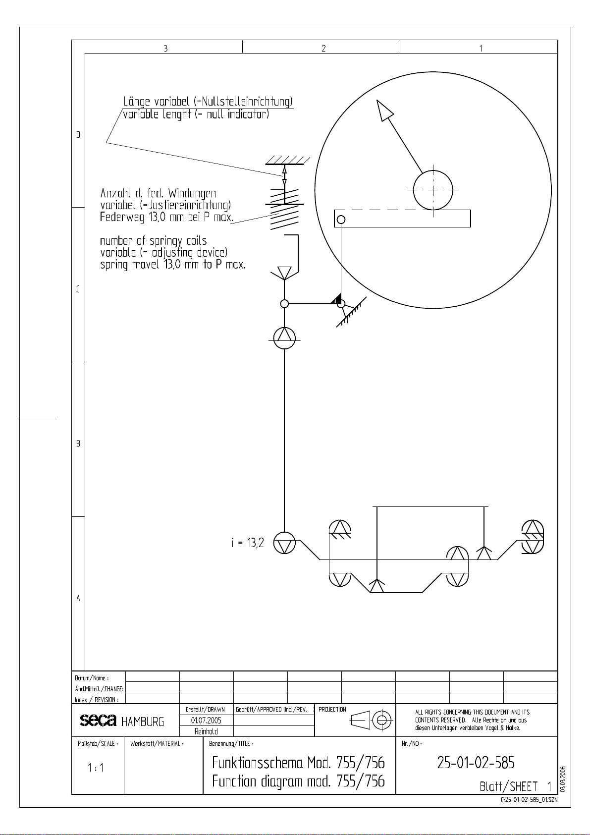
Function diagram 25-01-02-585
Calibration mod. 755 30-33-01-263 a
Calibration mod. 756 30-33-01-265
Replacement 30-33-01-262
Spare parts Head 30-33-01-261 a
Spare parts baseframe 30-02-00-204 b
Manual number: 17-05-01-327- a
Service manual Justageanweisung / Calibration
2
1
Neigungsjustage / Linearitätsprüfung
-Waage, bis auf Sichtscheibe komplett montiert, belasten.
-Waage 3 x mit Volllast (160 kg) belasten und wieder entlasten.
- Waage an der Nullstelleinrichtung (1) auf 0 stellen.
- Waage mit 160 kg belasten und Neigung mittels Justierschlüssel
15-02-08-204 am Justierkern (2) einstellen.
Achtung hierbei verschiebt sich der Nullpunkt.
-Waage entlasten und erneut auf „0“ stellen.
-Waage erneut belasten, dieser Vorgang ist solange wiederholen, bis folgender Wert erscheint: F = 160 kg Anzeige
160 kg +/- 0,75 kg
-Einstellung der Zwischenwerte. z.B. bei 50 kg und 100 kg sind durch ein verschieben vom Zifferblatt zu erreichen.
Ersteichungsfehlergrenzen nach EN (DIN) 45 501 Eichklasse IIII für
Max 160 kg – Min 5 kg – d = e = 500 g
Belastung 5 kg bis 25 kg Fehler +/- 0,25 kg
Belastung 25 kg bis 50 kg Fehler +/- 0,5 kg
Belastung 50 kg bis 160 kg Fehler +/- 0,75 kg
Prüfung der BMI Skale
-Waage mit 20 kg belasten,
jetzt muss die Teilung vom Farbdruck rot-orange als senkrecht verlaufende Linie im Sichtfenster der BMI Skale zu
sehen sein.
Slope adjustment / Linearity checks
-Load the scale when it is completely assembled, except for the sight glass
-Load the scale to maximum capacity (160 kg) three times and remove the load.
-Set the scale to “0“ using the zero point setting device (1)
-Load the scale with 150 kg and adjust the slope at adjusting core (2) using
adjusting key 15-02-08-204. Attention: The zero point will shift.
-Remove the load and readjust the scale to “0“ .
-Load the scale again. Repeat the procedure, until F = 150 kg 150.0 +/- 0.75 kg is displayed.
Intermediate values can be obtained by moving the dial face.
First calibration tolerances according to EN (DIN) 45 501, accuracy class IIII
max 150 kg – min 5 kg – d = e = 500 g
5 kg to 25 kg load :tolerance +/- 0.25 kg
25 kg to 50 kg load :tolerance +/- 0.5 kg
50 kg to 150 kg load :tolerance +/- 0.75 kg
Checking BMI chart:
Load the scale with 20 kg
Now the splitting of the colour print of the BMI chart in the viewing glass must be seen as a red-orange vertical line.
14.07.05/Reinhold 30-33-01-263
Service Manual Calibration
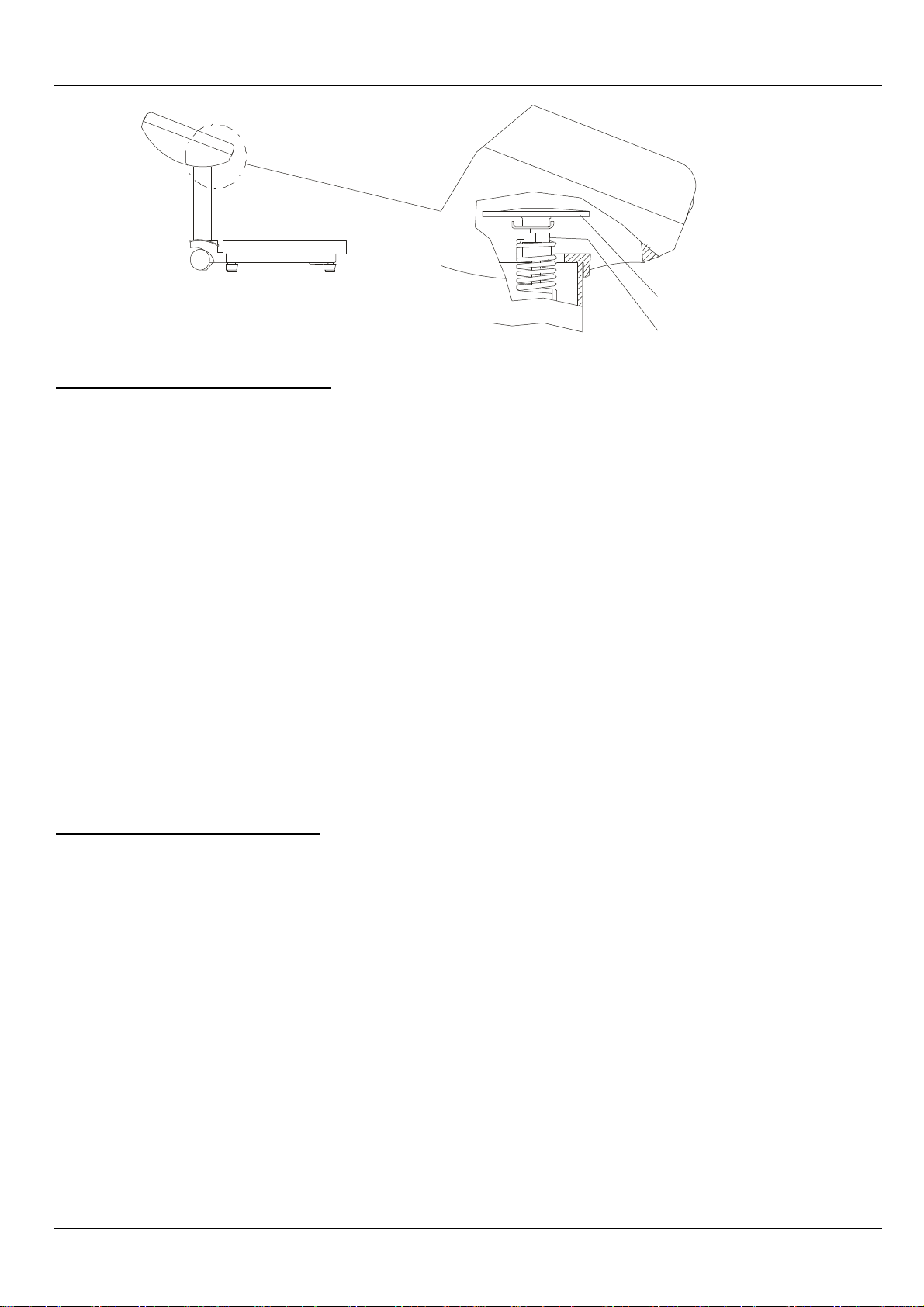
Span adjustment / linearity check, model 756
Caution: The zero point will shift.
1. Place the full load (160 kg) on the completely assembled scale and remove the load again. Repeat
this two more times.
2. Then place a 160 kg weight on the scale and check the variation.
There are two options for span adjustment.
Fine adjustment as described in section 3.
For larger variations and for linearity adjustment follow the instructions in section 5.
3. Fine adjustment.
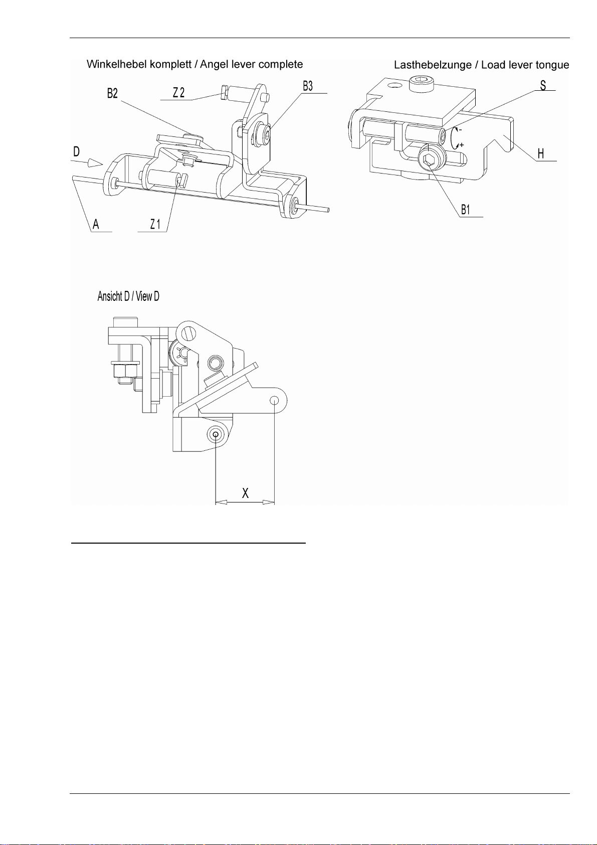
Use hex key S3 to release screw (B1) and to adjust adjuster screw (S) on the load lever tongue
(H). When a positive deviation was detected under full load, turn the adjuster screw (S) clockwise.
When a negative deviation was detected, turn the adjuster screw (S) counterclockwise.
One revolution (360°) of the adjuster screw corresponds to 0.4 kg on the dial display.
4. The load lever tongue provides a max. setting range of +/- 4 kg.
If the setting range provided by the load lever tongue is not sufficient, remove the viewing glass,
the
pointer and the dial.
20.09.06/ Sie, Eg, Rei 2 30-33-01-265

Service Manual Calibration
5. The following settings can be made via the angle lever. Release screws (B2) and/or (B3) for this
purpose.
If a positive deviation under full load is detected, the distance between axle (A) and pivot (Z1) must
be reduced. The distance must be increased in case of a negative deviation.
If a positive deviation was detected under half load (80 kg), the angle between pivots (Z1) and (Z2)
must be increased. The angle must be reduced if a negative deviation was found.
6. Tighten the screws and refit the dial and the pointer after each correction.
Repeat the procedure described in sections 3 and 5 several times if necessary.
7. Check the display at 40 kg and 120 kg before finally securing the dial. Display errors can be
adjusted by moving the dial upwards or downwards a bit.
8. Finally, secure all parts you have removed. Do not tighten the dial screws too firmly.
Calibration check
Lasthebelzunge H
Load lever tongue
1
-Remove the load and readjust the scale with the Zero setting device (1) to “0“ .
-place a 100 kg / 160 kg weight on the scale and compare the max display difference with
the allowed error dimension.
First calibration tolerances according to EN (DIN) 45 501, accuracy class IIII
max 160 kg – min 5 kg – d = e = 500 g
5 kg to 25 kg load :tolerance +/- 0.25 kg
25 kg to 100 kg load :tolerance +/- 0.5 kg
100 kg to 160 kg load :tolerance +/- 0.75 kg
Checking BMI chart:
Load the scale with 20 kg
Now the splitting of the colour print of the BMI chart in the viewing glass must be seen as a redorange vertical line.
20.09.06/ Sie, Eg, Rei 2 30-33-01-265

Service manual Replacement instructions
1. Opening the display head
1.1 Turn the dial glass "S" counterclockwise and remove it.
1.2 Remove the dial protecting ring "ZR".
1.3 Pull the pointer "Z" vertically upwards to pull it off the pinion "R", pressing the
pinion down.
1.4 Slacken the two 35x8 recessed head screws "KS1“ that hold the dial. Remove
the dial "ZB".
2. Dismantling the display head
2.1 Unhook the tie rod "ZS" from the load lever.
2.2 Release the two M35x8 recessed head screws on the pinion bearing block
"RB". Remove bearing block and pinion as well as the BMI scale "BMI".
2.3 Unhook the tension spring on the toothed rack "ZS" and unhook the toothed
rack from the angle lever "WH".
2.4 Unhook the axle "A" for the angle lever "WH" from the bottom part of the head.
2.5 Extract the two recessed head screws in the pressure plate "DP" for the taring
unit from the bottom part of the head and the column. Pull the taring unit
together with the angle lever "WH" and the tie rods up and out of the column.
2.6 This action (step 2.5) also releases the bottom part of the head between
column and pressure plate.
2.7 Now all tie rod parts can be detached from the taring unit and the angle lever.
3. Dismantling the baseframe
3.1 Unhook the tie rod "ZS" from the load lever.
3.2 Turn the scale over and set the weighing platform on a table of suitable height
or a similar worktop. Make sure that none of the parts still attached to the
platform come in contact with the floor.
3.3 Only if the column or the entire baseframe is to be replaced.
Slacken the two M6x20 recessed head screws that hold the column.
3.4 Release the two platform locking devices "BS".
3.5 Do not remove any components apart from the column yet, but turn the entire
baseframe over again.
3.6 Lift off the platform. Now all the components in the baseframe can be
replaced.
3.7 By unhooking the two cross-ties "T", the complete set of load levers can be
dismantled.
4. Replacing the column
4.1 Remove the display head, following steps 1.1 to 1.5 and 2.4 to 2.6.
4.2 Remove the baseframe, following steps 3.1 to 3.3.
02.06.05 1/4 30-33-01-262

Service manual Replacement instructions
5 Assembling the scale
Reassemble the scale in reverse order, following steps 3 to 1.
Please note:
5.1 On the taring unit, the distance between the adjusting block and the pressure
plate for the taring knob must be 2 mm. The distance can be adjusted by
turning the taring knob.
5.2 When performing step 2.2 in the fitting sequence, first tighten up the bearing
block and then insert the pinion.
5.2.1 On scales with BMI scale, fit the pinion together with the BMI scale; make sure
the print is in the correct position. The mark on the BMI scale must be below
the zero position of the pointer that is fitted later.
For the installation position of the BMI – scale see also 30-33-01-264 page 1
02.06.05 1/4 30-33-01-262


Service Manual Spare parts list
seca 755 / 756 Head
item Articel no. Designation Price stage
01 01-22-13-321-009 Headpiece 25
02 01-22-13-322-009 Headpiece bottom part 25
03 01-22-07-289-009 BMI scale 24
04 01-22-07-287-009 Dial plate calibrated with BMI mod. 756 24
01-22-07-283-009 Dial plate calibrated mod. 756 24
01-22-07-293-009 Dial plate kg mod. 755 24
01-22-07-294-009 Dial plate kg / lbs, mod. 755 24
01-22-07-295-009 Dial plate kg, BMI mod. 755 24
01-22-07-296-009 Dial plate kg / lbs, BMI mod. 755 24
05 01-22-13-324-009 Viewing glas 20
06 01-22-13-325-009 Dial protection ring 20
07 01-22-09-211-009 Pointer 10
08 01-22-13-320-009 Pressure plate mod. 755 05
01-22-13-344-009 Pressure plate mod. 756 05
09 01-07-04-013-009 Taring paket compl. mod. 755 18
01-07-03-001-009 Spring bracket compl. mod. 756 18
10 01-02-03-046-009 Angel lever compl. mod. 755 10
01-02-03-047-009 Angel lever compl. mod. 756 10
11 01-07-05-296-009 Axle for angel lever 01
12 01-02-03-246-009 Tie rod for angel lever 10
13 01-02-05-027-009 Tie rod compl. mod. 755 10
01-02-05-028-009 Tie rod compl. mod. 756 10
14 01-14-03-222-009 Tooth rack 13
alternative
01-14-03-205-009 Tooth rack 13
15 01-07-01-206-009 Tension spring 06
16 01-14-01-002-509 Pinion with bearing block compl. 17
01-14-01-003-509 Pinion with bearing block compl. with BMI skale 26
17 19-17-03-232-009 Spacer measuring rod 25
19-17-03-233-009 Cover for spacer 10
16.11.06/Re page 1 (2) 30-33-01-261b


Service Manual Sparepartslist
New mechanical column scales CN
seca Baseframe 755 / 756
Spare parts drawing see 30-02-00-204 Page 02
Item Articel no. Designation price stage
01 02-02-03-107-807 Frame compl. mod. 755 non-calibrated 41
with wheel, adjusting foot, cap
02-02-03-108-807 Frame compl. mod. 756 calibrated 41
with wheel, adjusting foot, cap, bubble level
02 01-17-01-204-009 Bubble level only calibrated models 15
01-13-05-398-807 Cap only non-calibrated models 01
03 01-10-04-221-009 Levelling device 15
04 01-13-05-397-816 Threaded plug levelling device 05
05 01-13-05-399-816 Cap column connection 01
06 01-12-02-002-009 Roller compl. with axle and holder 20
07 01-01-06-089-009 Cross bar compl. for all models 15
08 01-01-01-069-009 Corner attachment 10
09 02-06-03-057-009 Lever set comp. mod. 755 non-calibrated 35
02-06-03-058-009 Lever set comp. mod. 756 calibrated 35
10 01-04-07-215-009 Lever guide 10
02-06-03-065-009 Lever guide tongue adjustable only for mod. 756 calibrated 10
11 01-01-03-221-009 Centre suspension 10
12 02-02-03-295-816 Column connection oval 20
13 02-04-03-068-816 Platform compl. with caps and mat 25
14 01-13-04-343-009 Platform mat 15
15 01-03-04-247-009 Cap for platform mat 08
04-02-06-041-807 Column kompl. mod. 755/756 34
21.11.06/Rei Seite 1 (2) 30-02-00-204b

 Loading...