

SEA Unigate FV User Manual
Automatic Gate Openers
1
Unigate FV
R
ITALIANO
ENGLISH
FRANÇAIS
ESPAÑOL
SEA S.p.A.
Zona industriale 64020 S.ATTO Teramo - (ITALY)
Tel. +39 0861 588341 r.a. Fax +39 0861 588344
www.seateam.com seacom@seateam.com
Rev. 03 - 03/2019cod. 67412090
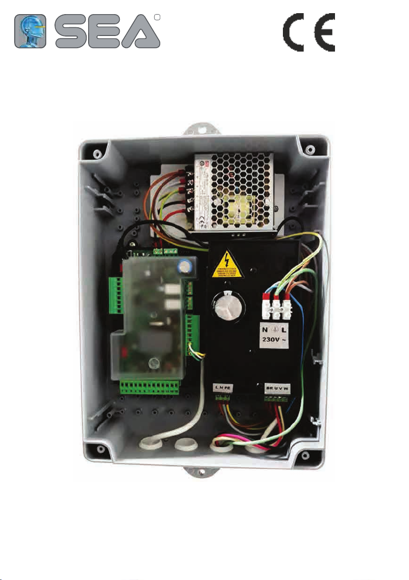
COMPONENTS
2
Control unit power supply: 230 Vac 50/60 Hz - 115Vac 50/60 Hz
Absorption in stand by: 30 mA
Environment temperature: -20°C +50°C
Specications of external box: 325,7 X 246 X 140
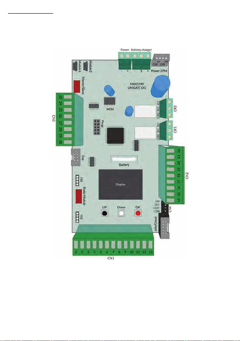
ENGLISH
CN1 = Input/output connectors
CN2 = Limit switch, 24V~, Electric lock connector
CN3 = Encoder terminal board/PositionGate/gp1/gp2
Jolly/Cloud connector Jolly 3 or Sea Cloud
FIX = FIX receiver plug in connector
CR1 = Relay 1 clean contact terminal
CR2 = Relay 2 clean contact terminal
2PM = 2PM module power supply connector
CNB = Batterie charger connector
CNP = Programming connector
CLS = Limit switch quick connector
Power - + = Power supply switching connector
Module 1 = Motor 1FV module/2PM module connector
Module 2 = Motor 2 FV module
Master/Slave = Mater/Slave card connector
Progr = Programming connector through Open
Exp = SEM 2 external module connector
CNR = UNI receiver connector
Battery = Back up battery CR 2032
MEM = Radio trans. memo for FIX receivers
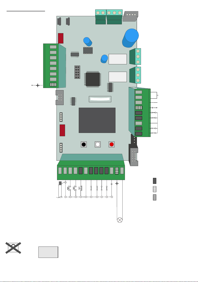
CONNECTIONS
+PG positive Position Gate
E1D1 Position gate data 1/
E2D2 Position gate data 2/
24V (1A max)
(+ encoder)
Encoder 1
COM
Encoder 2
GP1 input
GP2 input
COM (-)
Module1
Master/Slave
Module2
Power Battery charger
-+ -S +
54001590
UNIGATE DG
5V 24V
COM
COM
Power 2 PM
ENGLISH
23
24 25 26 27 28 29 30
CN3
Exp
Radio Module
FIXFIX
MEM
Progr
Battery
Display
UP Down OK
11
LSC1
LSC01
COM
CR1 CR2
COM1 NO1 NC1 COM2 NO2 NC2
24V
CNF
COM2 NO2 NC2
COM1 NO1 NC1
2212029181716141 51
Clean contact
Clean contact
Electro lock
COMIS
(common accessories)
24V (1A max)
Closed limit switch
M2
Opened limit switch
M2
Comune
Closed limit switch
M1
Opened limit switch
M1
CN1
Jolly/Cloud
1
2 3 4 5 6 7 8 9 10 11 12 13
FL -
24VDC
24VAC
Antenna
Common
Common
Start Pedestrian
Loop 1- Photocell 1
Loop 2- Photocell 2
Common
Flash Light
Security edge 1
Security edge 2
(500 mA max)
aux Programmabile
(24 VDC --- 1A max)
Stop
Start
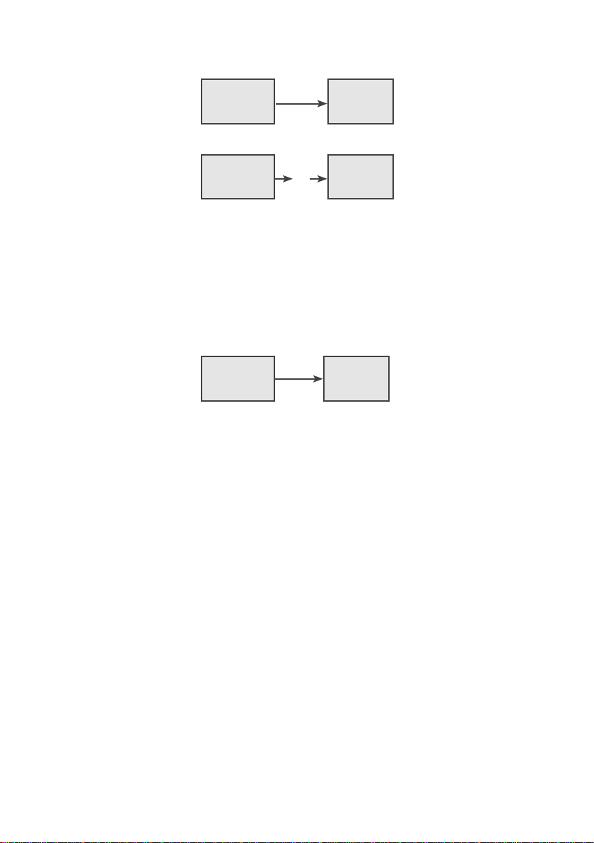
Warning: Automatic detection of not used N.C. inputs (Photocells, Stop, Limit switch and Edges)
To reactivate an NC contact, follow this procedure:
Go to and press OK for 5 seconds, then enter the INPUT CHECK MENU and
MENU
V 00.14 or
subsequent
SEA
SET
check the operating status of all inputs
No need to repeat self programming after reactivation of N.C. contacts.
The herein reported functions are available starting from revision 00.14
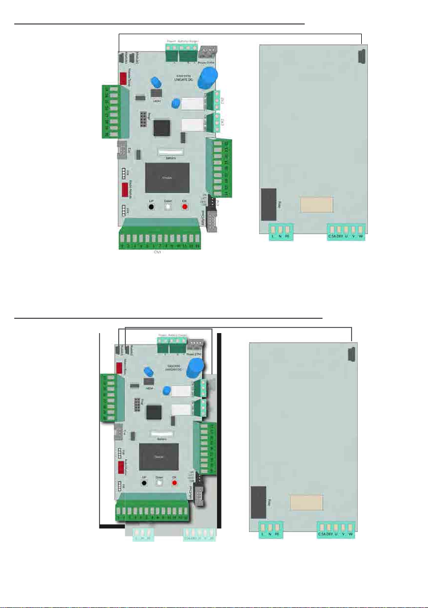
UNIGATE CONNECTION WITH AN INVERTER MODULE
CN2
Dry contact and
motor output
4
ENGLISH
USB
L : phase
N: neutral
CN1
Inverter power supply
230 115 Vac
PE: ground
It is mandatory to connect the ground cable to the PE input
UNIGATE CONNECTION WITH TWO INVERTER MODULES
CN2
Dry contact and
motor output
USB
USB
CN1
L : phase
N: neutral
Inverter power supply
terminal
230 115 Vac
PE: ground
It is mandatory to connect the ground cable to the PE input
CN1
Inverter power supply
terminal
230 115 Vac
CN2
Dry contact and
motor output
USB
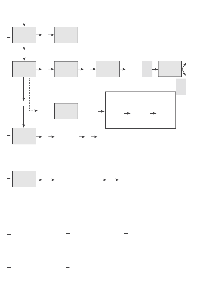
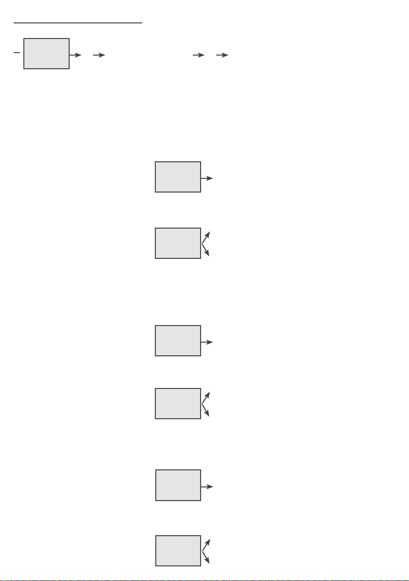
PARAMETER AND NO/NC CONTACTS PRE-CONFIGURATION
5
1)
Start
Limit switch
opening motor 1
Limit switch
closing motor 1
Photocell 1 Edge 1 Edge 2
- When N.C.
(Photo, Stop, Limit
switch and Edge)
DISPLAY INPUTS STATUS
Pedestrian
opening
MENU
SEA
- - -
- - - -
- - - -
Photocell 2
MENU
MENU
SEA
SEA
When not engaged or
SET
not wired
When the photocell
SET
is crossed or input is
engaged
SET
Stop
Limit switch opening motor 2
(or slow opening BIG FAST)
Limit switch closing motor 2
(or slow closing BIG FAST)
N.C. contacts
ENGLISH
.
.
N.O. contacts
- When N.O.
(Start, pedestrian
start)
MENU
MENU
SEA
SEA
SET
When input is engaged
When input is not
SET
engaged
2)
Power OFF
3)
Keep pressed the two buttons UP and DOWN and, at the same time, connect the power supply
cable for initialization of the control unit INIT appears on the display or go to menu 14: RESET
MENU
MENU
SEA
INIT
SEA
4)
SET
All parameters return to default conguration, see column “Default” in the table of the
menus and all the inputs will show their real status
5)
SET
All NC contacts are automatically switched off if not used (no segments on display).
If the contacts are connected, they will be On on the display (segment switched on).
To reactivate the NC contacts it is necessary to enter each menu which shows the NC contacts
(e.g.: STOP, PHOTO, EDGE, LIMIT SWITCH....) and with SET put them on ON.
QUICK STArT AND proGrAMMING
6
UP
SEA SEA
MENU MENU
1
SET SET
LANGUAGE
OK
English
ENGLISH
2
MENU
Trasmitters
UP
SEA
SET
Skip this step if you don’t want to programm a transmitter
SEA
START
SET
OK
MENU
OK
MENU
SEA
PRESS
BUTTON
SET
Press the
button of
the TX to be
stored
After programming connect the antenna
Remote control programming
UP
SEA
MENU
3
MOTOR
SET
If on the
display
appears
the item:
OK
SEA
MENU
SET
RECEIVER
MISSING
Choose the type
of motor with UP
or DOWN
check if a
receiver
has been
connected
OK
To conrm and
return to the
main menù
CHooSE BETWEEN SINGLE or DoUBLE LEAF
Default (ON) = Single leaf
SEA
SINGLE
LEAF
SET
MENU
3
Skip this step if you are working in sliding or single leaf mode
OK
With UP or DOWN choose
ON only if in single leaf mode
(motor 1)
OK
To conrm and
return to the
main menù
RX
Connector CNA
MENU
SEA
STORED
SET
To exit
Press
another
button or
another TX
to be store it
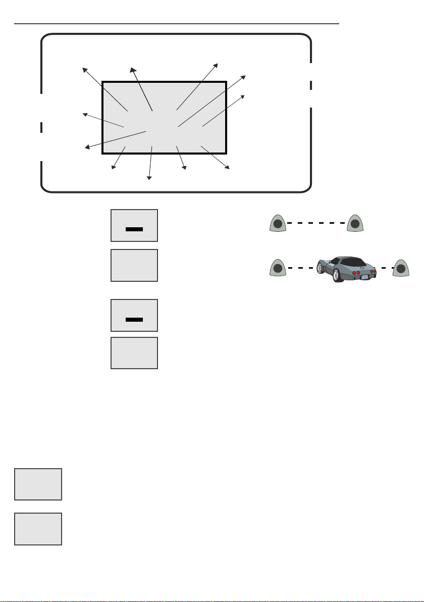
prESET INSTALLATIoN
ATTENTION: This procedure is potentially dangerous and must only be performed by specialized
personnel
Turn OFF the power
A
D E
Reset the mechanical lock
Example
Release
B C
Release the operators Manually push the leaves in half position
Example
Release
Put the power ON
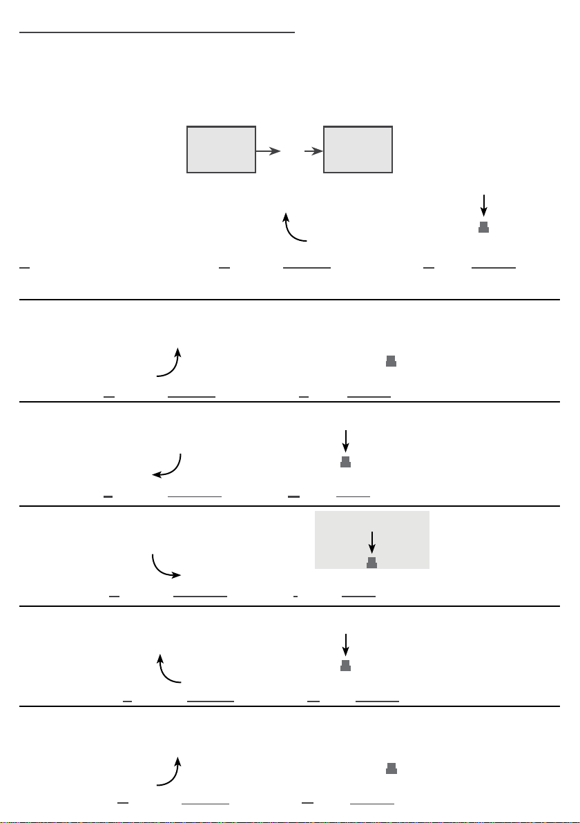
2 MOTORS MANUAL SELFLEARNING
7
A) WITH IMPULSES *
The gate will start the following cycle: M2 CLOSING - M1 CLOSING - M1 OPENING - M2 OPENING
- M2 CLOSING - M1 CLOSING. To store the respective stops during cycle, press UP or DOWN or
START on each mechanical stop point of the leaf. Self-learning has been completed. In the case of
a single leaf the cycle will be CLOSING 1 - OPENING 1 - CLOSING 1.
SEA SEA
MENU MENU
PROGRAMMING
SET SET
9
OK
OK
ENGLISH
M1
A
Both doors halfway
M1
D
M1
F
M1
H
M2
M1 in closing
M1 in opening
M2 in opening
M1
B
M2 in closing
M2
M2
M2
M2
M1 M2P1
E
M1 closed
M1
P1
G
M1 open
M1 M2P1
I
M2 open
M1
C
Press UP or TX, if stored, when
M2
P1
M2 closed
M2 is closed position.
Press UP or TX, if
stored, when M1 is
closed position.
Press UP or TX, if
stored, when M1 is
open position.
Press UP or TX, if
stored, when M2 is in
open position.
Press UP or TX, if
stored, when M2 is in
closed position.
M2
M1
L
M2 in closing
M1
N
M1 in closing
M2
M2
M1
M
M1
O
M1 closed
P1
M2 closed
P1
M2
Press UP or TX, if
stored, when M1 is in
closed position.
M2
AUToMATIC SELF-LEArNING 2 MoTorS
8
ENGLISH
Make sure that, for all types of self-learning, the gate performs the following cycle: M2 CLOSING,
M1 CLOSING, M1 OPENING, M2 OPENING, M2 CLOSING, M1 CLOSING. Otherwise, see the
MOTOR REVERS function.
The cycle in case of single leaf will be CLOSE MOTOR 1 - OPEN MOTOR 1 - CLOSE MOTOR 1.
B) ENCoDEr *
When an Encoder is installed, it is necessary to select ON in the 32-ENCODER menu
Note: to adjust sensitivity on obstacle refer to the special menu
SEA
MENU
32 - encoder
SEA
MENU
9
programming
SET
OK
SET
OK
MENU
MENU
SEA
ON
SEA
ON
SET
SET
SELF-LEARNING starts AUTOMATICALL Y.
Now it is necessary to wait until the leaf or leaves rst start closing and then automatically complete
the CLOSING - OPENING - CLOSING cycle.
C) poTENTIoMETEr *
When the potentiometer is installed, it is necessary to select
SEA
MENU
32 - encoder
SET
OK
SEA
MENU
potentiomer
SET
SELF-LEARNING starts AUTOMATICALL Y
SEA
MENU
9
programming
SET
OK
MENU
SEA
ON
SET
Now it is necessary to wait until the leaf or leaves start before closing and automatically complete
the cycle CLOSING - OPENING - CLOSING - OPENING with slowdown - CLOSING with slowdown
Note: to adjust sensitivity on obstacle refer to the special menu
SEA SEA
33
motor 1
SET
MENU
opening sensitivity
MENU
slowdown
sensitivity
SET
37
The potentiometer threshold intervention is set automatically during self-learning
IT IS NOT NECESSARY TO ADJUST THE MENU FROM
SEA
MENU
38 pot.
from threshold
to opening 1
SET
SEA
SET
MENU
45 pot. slowdown
threshold closing 2
Note 2: With the potentiometer you can also make the self-learning giving impulses on favourite
opening or closing points; In this case it is also possible to modify the parameters I.AP.M1, I.CH. 1,
I.AP.M2, I.CH.M2 of + 100 impulses, if you need to optimize the initial and the nal position
Nota 3: In the case of MIXED PROCEDURE (AUTOMATIC stop detection in closing and with
MANUAL input in opening) the learning cycle will only be CLOSE-OPEN-CLOSE.
D) AMpEroMETrIC* (For electromechanical motors only)
9
ENGLISH
This type of selearning is possible ONLY for electromechanical operators and physical stops.
SEA
MENU MENU
SET
3 MOTOR MECHANIC
OK
SEA
SET
Note: to adjust sensitivity on obstacle refer to the special menu
SEA
MENU
PROGRAMMING
SET
9
OK
MENU
SEA
ON
SET
SELF-LEARNING starts AUTOMATICALL Y
At this point it is necessary to wait until the leaf or leaves start before closing and automatically
complete the CLOSING - OPENING - CLOSING cycle.
E) WITH LIMIT-SWITCHES*
1 - LIMIT SWITCH INPUT CHECK: check each limit switch on both doors by activating them before
self-learning. The segment on the display will disappear when each limit switch is activated
SEA SEA
MENU MENU
PROGRAMMING
SET
9
OK
SET
ON
SELF-LEARNING starts AUTOMATICALL Y
At this point it is necessary to wait until the leaf or leaves rst start closing and then automatically
complete the CLOSING - OPENING - CLOSING cycle.
*rEVErSE MoTor
If the motor starts in opening, turn power off and on again, select “5 - rEVErSE MoTor” on the
display through UP and DOWN press OK and put on ON, or, if you have the Jolly 3 programmer,
activate the motor exchange function.
opErATING FUNCTIoNS
10
ENGLISH
SEA
MENU
6
SET
Logic
Skip this step if you work in semi-automatic logic
Choose the desired logic with
OK OK
UP or DOWN
To conrm and return
to the main menu
ONLY AFTER THE SELF LEARNING OF WORKING TIMES WITH AUTOMATIC LOGIC, IT will BE
POSSIBLE TO CHANGE LOGICS INTO TO:
A) AUToMA TIC
A start impulse opens the gate. A second impluse during the opening will not be accepted.
A start impulse during closing reverses the movement.
NOTE 1: For automatic closing it is necessary to set a pause time, otherwise all the logics will be
semi-automatic.
SEA
7
Pause time
SET
more than 0 sec
MENU
NOTE2: It is possible to choose, whether to accept or not, the start in pause, selecting in the MENU
the item 8-START IN PAUSE and choosing ON or OFF. By default, the parameter is OFF.
SEA
MENU
8
start in pause
ON (accepts the start)
SET
OFF (doesn’t accepts the start)
B) SECUrITY
A start impulse opens the gate. A second impulse during opening reverses the movement.
A start impulse during closing reverses the movement.
NOTE 1: For automatic closing it is necessary to set a pause time, otherwise all the logics will be
semi-automatic.
SEA
7
Pause time
SET
more than 0 sec
MENU
NOTE2: It is possible to choose, whether to accept or not, the start in pause, selecting in the MENU
the item 8-START IN PAUSE and choosing ON or OFF. By default, the parameter is OFF.
SEA
MENU
8
start in pause
ON (accepts the start)
SET
OFF (doesn’t accepts the start)
C) STEp BY STEp TYpE 1
The start impulse follows the OPEN-STOP-CLOSE-STOP-OPEN logic.
NOTE 1: To have the automatic closing it is necessary to set a pause time, otherwise all the logic
will be semi-automatic.
SEA
7
Pause time
SET
more than 0 sec
MENU
NOTE2: It is possible to choose, whether to accept or not, the start in pause, selecting in the MENU
the item 8-START IN PAUSE and choosing ON or OFF. By default, the parameter is OFF.
ON (accepts the start)
SET
OFF (doesn’t accepts the start)
SEA
MENU
8
start in pause

D) STEp BY STEp TYpE 2
11
ENGLISH
The start impulse follows the OPEN-STOP-CLOSE -OPEN logic.
NOTE 1: To have the automatic closing it is necessary to set a pause time, otherwise all the logic
will be semi-automatic.
SEA
7
Pause time
SET
more than 0 sec
MENU
NOTE2: It is possible to choose, whether to accept or not, the start in pause, selecting in the MENU
the item 8-START IN PAUSE and choosing ON or OFF. By default, the parameter is OFF.
SEA
MENU
8
start in pause
SET
ON (accepts the start)
OFF (doesn’t accepts the start)
E) DEAD MAN
The gate opens as long as the START button of opening is pressed; releasing it the gate stops. The
gate closes as long as the button connected to the PEDESTRIAN START is pressed; releasing it
the gate stops. To execute complete opening and/or closing cycles the related pushbuttons must
be constantly pressed.
F) 2 BUTToNS
One start opens, one pedestrian start closes. In opening the closing will not be accepted. In closing
a start reopens, a pedestrian start (close) will be ignored.
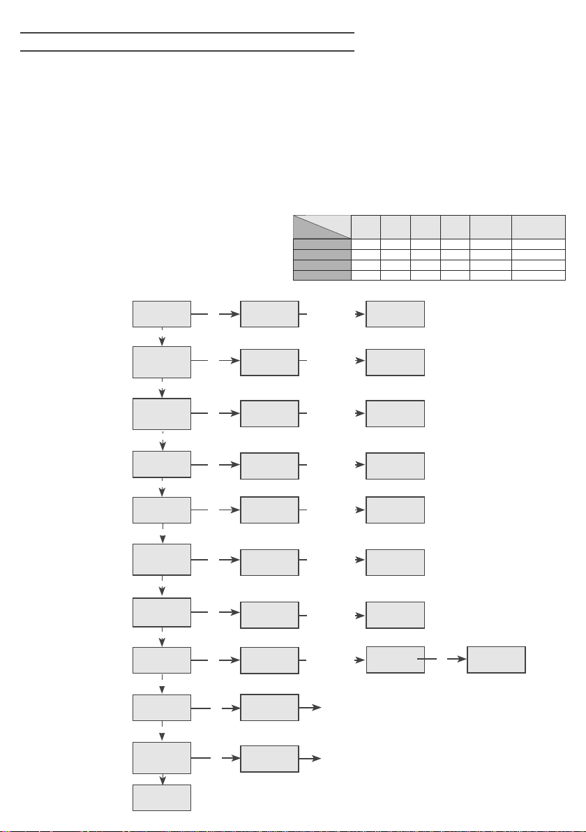
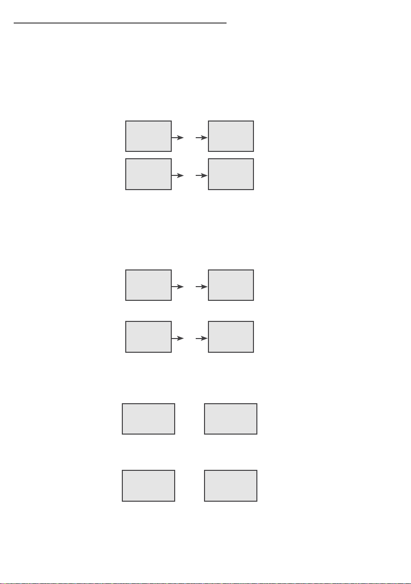
rADIo TrANSMITTEr SELF LEArNING WITH
12
ENGLISH
UNI rECEIVEr oN BoArD oF CoNTroL UNIT
WARNING: Make the radio transmitters programming before you connect the antenna and insert the receiver
into the special CMR connector (if available) with control unit turned off. With RF UNI and RF UNI PG module
it will be possible to use both Coccinella Roll Plus transmitters and radio transmitters with xed code. The rst
memorized radio transmitter will determine the type of the remaining radio transmitters. If the receiver is a
Rolling Code, press the button of the radio transmitter that you want to program twice to memorize the rst TX.
In the case of transmitters with xed code it is necessary to press 1 time the button of the transmitter you want
to program to store the rst remote control.
Notes:
- Perform the radio transmitters learning only with stopped cycle and closed gate.
- You can store max. 2 of the available 4 functions. If the control unit receives a code that has already been
assigned to another function it will be updated with the new function.
RF UNI
RF UNI PG
old model
RF UNI PG
new model
If you want to
program the
pedestrian start as
second channel
If you want to
program the
activation of the light
output as second
channel
If you want to
program the stop as
second channel
If you want to
program the second
channel to activate
relay CR1 or CR2
If you want to
program the stop as
bistale stop
If you want to
program a button as
electric brake release
If you want to delete
a single transmitter
Move the TX FIX’s
the extractable
memory (MEM)
If you want to delete
the whole memory
16 users without memory
800 users with additional memory MEM
100 users xed code
800 users roll plus
100 users xed code
800 users roll plus
SEA SEA SEA
SET SET SET
MENU MENU MENU
START
UP
SEA
MENU
Pedestrian
start
UP
SEA
MENU
External
module
UP
SEA
MENU
STOP
UP
SEA
MENU
RELAY
UP
SEA
MENU
Bistable
Stop
UP
SEA
MENU
Release
UP
SEA
MENU
Delete a TX
UP
SEA
MENU
Move on EEP
UP
SEA
MENU
Clear memory
SEA
END
OK
press button
SET
SET
SET
SET
SET
SET
SET
SET
for 10 sec
SET
for 10 sec
MENU MENU
OK
press button
MENU MENU
OK
press button
MENU MENU
OK
press button
MENU MENU
OK
press button
MENU
OK
press button
MENU
OK
press button
MENU
OK
MENU
OK
MENU
OK
Memory location
button of the
transmitter to
SEA SEA
SEA SEA
SEA SEA
SEA SEA
SEA
SEA
SEA
0
SEA
OK
SEA
OK
button of the
SET SET
transmitter to
button of the
SET SET
transmitter to
button of the
SET
transmitter to
button of the
SET SET
transmitter to
button of the
SET
transmitter to
button of the
SET
transmitter to
Select with UP
and DOWN
SET
the memory
location to be
selected and
SET
SET
TX button
1
0
1
2
3
Press the
be stored
Press the
be stored
Press the
be stored
Press the
be stored
Press the
be stored
Press the
be stored
Press the
be stored
press OK
Conrm the cancellation
Menu output
MENU
MENU
MENU MENU
If you do not want to cancel , press UP or DOWN to
3
2
stored
stored
stored
SET
stored
stored
SEA
SET
stored
SEA
SET
stored
SEA SEA
SET SET
ok? ok
return to the 2 transmitters menu
serial
4
number
customer
OK
 Loading...