

Page 1

Page 2

Page 3
Istruzioni per l'installazione,
l'uso, la manutenzione
I
Italiano, 1 Deutsch, 7 English, 13
E
Español, 19
RUS
кмллдав, 37
J 108
D GB
F
Français, 25NLNederlands, 31
Sommario
Installazione, 2
Istruzioni per il montaggio, 3
Manutenzione, 4
Sostituzione lampade, 5
CAPPE CONVERTIBILI
I
1
Page 4

Installazione
! L’apparecchio messo in opera dovrà distare dal
I
piano di lavoro non meno di cm. 65 nel caso di fornelli
elettrici e cm 65 nel caso di fornelli a gas o misti.
! Se le istruzioni di installazione del dispositivo di
cottura a gas specificano una distanza maggiore,
bisogna tenerne conto.
Collegamento elettrico
Prima di effettuare qualsiasi collegamento assicurarsi
che la tensione di rete corrisponda, alla tensione
riportata sull’etichetta caratteristiche situata all’interno
dell’apparecchio.
Si consiglia di delegare il collegamento elettrico ad un
tecnico qualificato.
Apparecchio provvisto di spina
Allacciarlo ad una presa conforme alle norme vigenti.
La spina, una volta inserita nella presa, deve trovarsi
in un punto facilmente accessibile.
Se si intende allacciarlo direttamente alla rete elettrica
togliere la spina ed applicare un interruttore bipolare a
norme con una distanza dei contatti in apertura non
inferiore a 3 mm.
Apparecchio sprovvisto di spina
Applicare una spina a norme oppure un interruttore
bipolare a norme con una distanza dei contatti in
apertura non inferiore a 3 mm.
Si declina ogni responsabilità per inconvenienti
derivati dall’inosservanza delle suddetta
disposizione.
L’APPARECCHIO IN CL 1 DEVE ESSERE
COLLEGATO AD UN IMPIANTO DI TERRA
L’allacciamento deve essere eseguito come segue:
MARRONE = L ( linea)
BLU = N (neutro)
GIALLO/VERDE = (terra)
L’APPARECCHIO IN CL 2 NON DEVE ESSERE
COLLEGATO AD UN IMPIANTO DI TERRA
Per gli apparecchi in classe 2°, recanti sulla etichetta
caratteristiche il simbolo del doppio quadrato,
l’allacciamento deve essere eseguito come segue:
MARRONE = L ( linea)
BLU = N (neutro)
Utilizzazione
La cappa è realizzata per essere utilizzata in versione
aspirante ad evacuazione esterna o filtrante a ricircolo
interno.
2
Page 5
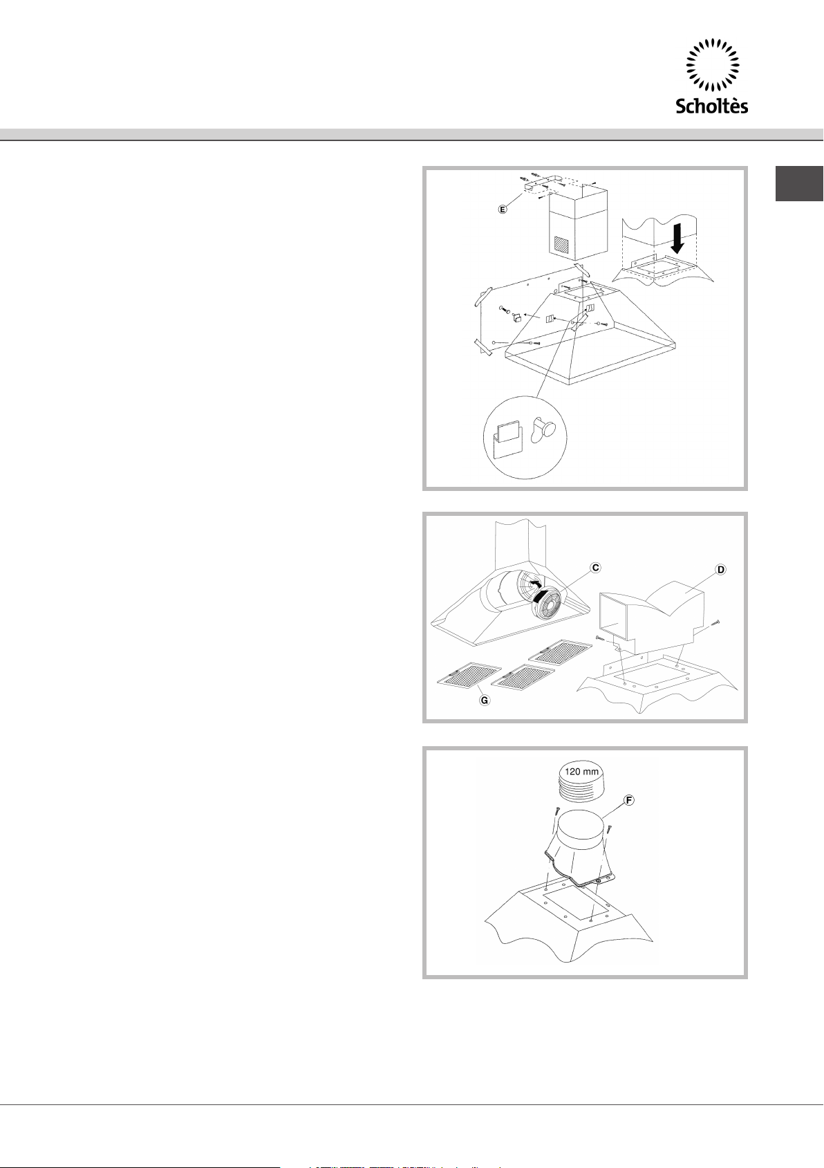
Istruzioni per il montaggio
Fig. 1
• Posizionare la dima centralmente ed eseguire le
relative forature.
• Inserire i tasselli al muro.
• Inserire 2 viti nei fori intermedi senza avvitare
completamente.
• Appendere la cappa sulle 2 viti attraverso le asole
sagomate presenti nella parte posteriore e
stringere.
• Bloccarla definitivamente con viti e rondelle.
• Viti e tasselli sono forniti a corredo.
Versione aspirante
Per poter utilizzare questa funzione munirsi di un tubo
flessibile Ø 120 mm. da collegare al raccordo “F”
Fig. 3 che andrà successivamente fissato al soffitto.
Versione filtrante fig. 2
• Quando non si ha la possibilità di evacuare l’aria
all’esterno, si utilizza un filtro a carboni attivi.
L’aria viene depurata dal filtro e rimessa
nell’ambiente.Le operazioni da eseguire sono :
• fissare il raccordo filtrante “D”
• infilare e ruotare i due filtri al carbone “C”
lateralmente.
• per convertire la cappa da ASPIRANTE a
FILTRANTE richiedere al venditore o alla ditta
costruttrice il corredo di montaggio.
Fig. 1
Fig. 2
I
Montaggio camino fig. 1
• Fissare la staffa “E”, per mezzo delle due viti e
tasselli ø8mm nell’asse centrale della cappa ,in
modo tale che il camino montato sia aderente al
soffitto.
• Infilare i camini uno dentro l’altro e fissare la parte
superiore alla staffa “E”.
Fig. 3
3
Page 6

Manutenzione
Disinserire l’apparecchio dalla rete elettrica prima di
I
effettuare qualsiasi operazione di manutenzione.
ll buon funzionamento della cappa è condizionato
dall’assiduità con cui vengono effettuate le operazioni
di manutenzione in modo particolare delle griglie
alluminio “G”e del filtro a l carbone attivo “C”.
Le griglie hanno il compito di trattenere le particelle
grasse o solide in sospensione nell’aria. Pertanto sono
soggette ad intasarsi in tempi variabili a secondo
dell’uso e del tipo di cucina.
Le griglie in alluminio stirato vanno lavate a mano o in
lavastoviglie una volta al mese lasciandole asciugare
prima del montaggio. In caso di inadempienza delle
istruzioni di lavaggio c’è pericolo di incendio.
Filtro carbone
Il filtro al carbone attivo, presente solo nella versione
filtrante, ha la funzione di trattenere gli odori e
depurare l’aria. La saturazione del filtro carbone si
verifica dopo un uso più o meno prolungato a seconda
del tipo di cucina e della regolarità della pulizia delle
griglie alluminio. In ogni caso è necessario sostituire la
cartuccia al massimo ogni quattro mesi.
Pulire frequentemente tutti i depositi sul ventilatore e le
altre superfici, usando un panno inumidito con alcool
denaturato o detersivi liquidi neutri non abrasivi.
4
Page 7
Sostituzione lampade
Sostituzione lampade ad incandescenza
40W (E14) max
• Disinserire l’apparecchio dalla rete elettrica.
• Rimuovere la griglia.
• Sostituire la lampada danneggiata con nuova di
ugual valore.
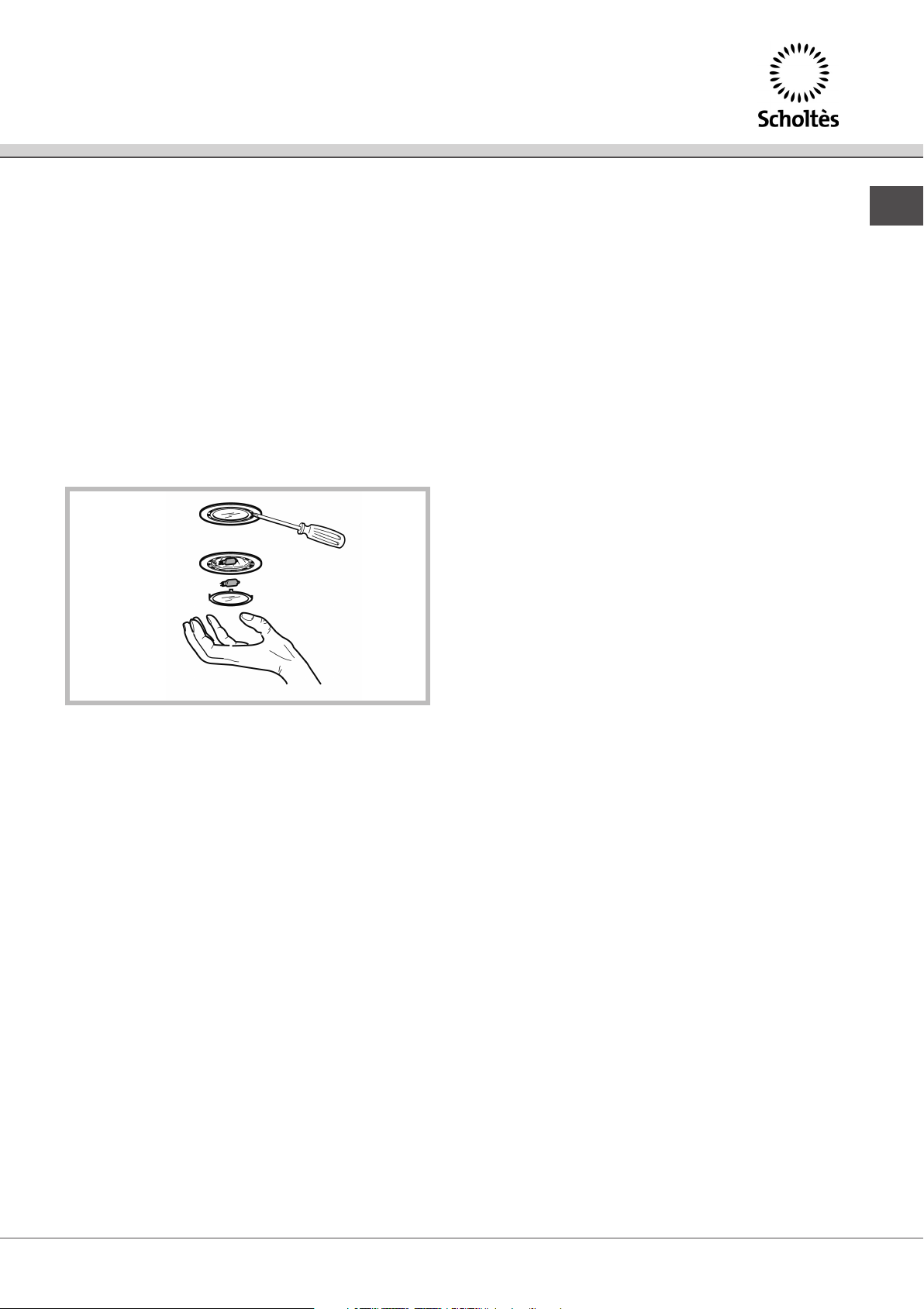
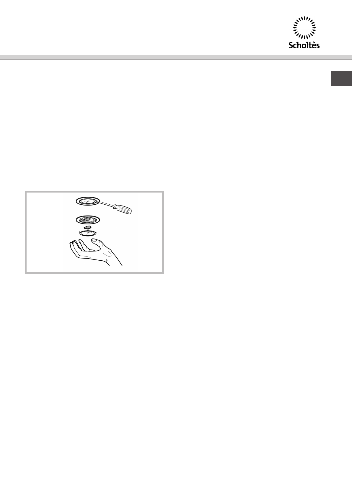
Sostituzione lampade alogene fig. 4
• Disinserire l’apparecchio dalla rete elettrica.
• Rimuovere estraendo il telaio porta-vetro del faretto.
• Sostituire le lampade danneggiate utilizzando
esclusivamente lampade alogene da 20 W-max.
Fig. 4
I
5
Page 8

ATTENZIONE
I
! L’evacuazione non deve essere convogliata nè in un
camino funzionante per lo scarico dei fumi o di gas
combustibili, nè in un condotto utilizzato come canna
fumaria per ambienti in cui sono installati fonti con
fuochi aperti. Per incanalare i vapori devono essere
rispettate le disposizioni delle autorità competenti. In
caso di funzionamento della cappa con evacuazione
esterna e funzionamento di altre fonti con fuochi
necessitanti di canna fumaria, ci si deve accertare che
vi sia sufficente apporto d’aria.
• Non cercate di controllare i filtri con la cappa in
azione.
• Non ostruite le uscite di scarico dell’aria.
• Non toccare le lampadine o il copri-lampada dopo il
protratto uso dell’apparecchio.
• E’ vietato cuocere cibi alla fiamma sotto la cappa.
• Evitare la fiamma libera, perchè dannosa per i filtri e
pericolosa per gli incendi.
• Controllare costantemente la frittura per evitare che
l’olio surriscaldato prenda fuoco.
• Prima di effettuare manutenzioni disinserire la
cappa dalla rete elettrica.
Si declina ogni responsabilità per eventuali danni
provocati dall’inosservanza delle suddette
avvertenze.
6
Page 9
Informationen fuer installation,
Gebrauch, Wartung
I
Italiano, 1 Deutsch, 7 English, 13
E
Español, 19
RUS
кмллдав, 37
J 108
D GB
F
Français, 25NLNederlands, 31
Inhalt
Montage, 6
Montageanweisungen, 7
Wartung und pflege, 8
Wechseln der glühlampen, 9
HAUBEN
D
7
Page 10

Montage
D
! Der eingebaute Dunstabzug sollte sich im Falle von
Elektroherden in einem Abstand von mindestens 65
cm von der Arbeitsfläche befinden und im Falle von
Gas- oder Mischherden in einem Abstand von
mindestens 65 cm.
! Sollten die Installationsanweisungen einen größeren
Abstand der Gaskochvorrichtung vorschreiben, so
sind diese Angaben zu berücksichtigen.
Elektrischer Anschluß
Vor dem Anschluß muß sichergestellt werden, daß die
Netzspannung den auf dem Typenschild (im Innern
des Gerätes) angegebenen Werten entspricht.
Bitte lassen Sie den Elektroanschluß ausschließlich
durch Fachpersonal durchführen.
Mit Stecker bestücktes Gerät
Schließen Sie das Gerät an eine den einschlägigen
Bestimmungen entsprechende Steckdose an.
Der angeschlossene Stecker sollte sich an einer leicht
zugänglichen Stelle befinden.
Sollte das Gerät direkt an das Stromnetz
angeschlossen werden, ist der Stecker zu entfernen,
und eine Trennvorrichtung mittels eines
vorschriftsmäßigen zweipoligen Schalters mit einer
Kontaktöffnung, die 3 mm nicht unterschreiten darf, zu
installieren.
oder einem zweipoligen Schalter mit einer
Kontaktöffnung, die 3 mm nicht unterschreiten darf.
Jegliche Haftung für Schäden, die durch
Nichteinhaltung obiger Anweisungen auftreten,
wird zurückgewiesen.
GERÄTE DER KLASSE 1 MÜSSEN AN EINEN
ERDLEITER ANGESCHLOSSEN WERDEN
Der Anschluß ist wie folgt vorzunehmen:
BRAUN = L (Leitungsnetz)
BLAU = N (Nulleiter)
GELB/GRÜN = (Erde)
GERÄTE DER KLASSE 2 ERFORDERN KEINEN
ERDANSCHLUSS
Geräte der Klasse 2, auf deren Typenschild das
Symbol eines Doppelvierecks abgebildet ist, sind wie
folgt anzuschließen:
BRAUN = L (Leitungsnetz)
BLAU = N (Nulleiter)
Betriebsarten
Diese Dunstabzugshaube kann sowohl im
Abluftbetrieb (Ansaugfunktion), als auch im
Umluftbetrieb (Filterfunktion) eingesetzt werden.
Gerät ohne Stecker
Versehen Sie das Gerät mit einem vorschriftsmäßigen,
den einschlägigen Normen entsprechenden Stecker
8
Page 11

Montageanweisungen
Abb. 1
• Legen Sie die Bohrschablone mittig an und bohren
Sie die entsprechenden Löcher.-Setzen Sie die
Wanddübel ein.
• Fügen Sie 2 Schrauben in die mittleren Löcher ein,
ohne sie jedoch gänzlich anzuziehen.
• Hängen Sie die Dunstabzugshaube mittels ihrer
rückseitigen Langlöcher in die Schrauben ein und
ziehen sie diese an.
• Befestigen Sie die Dunstabzugshaube daraufhin
definitiv durch Schrauben und Unterlegscheiben.
• Schrauben und Dübel werden als Zubehör geliefert.
Absaugfunktion
Damit diese Version zum Einsatz Kommen Kann Rohr
mit Ø 120 mm. Anschlußring “F” Fig.3 befestigen.
Danach das Rohr an der Decke befestigen.
ACHTUNG:
Bei gleichzeitigem Betrieb der Dunstabzugshaube im
Abluftbetrieb und Feuerstätten darf im Aufstellraum
der Feuerstätte der Unterdruck nicht höher als 4
Pa(4x10 –5 bar) sein.
Abb. 1
Abb. 2
D
Version mit filter Abb.2
• Falls keine Möglichkeit besteht, die Luft nach außen
abzuleiten, wird ein Aktivkohlefilter verwendet.
In diesem Fall wird die Luft vom Filter gereinigt und
wieder in den Raum abgegeben. Folgende Schritte
sind dazu durchzuführen:
• Befestigen Sie das Verbindungsstück “D”
• Setzen Sie die beiden Kohlefilter “C” seitlich ein und
drehen Sie diese
• Um die Abzugshaube von ABLUFTBETRIEB auf
UMLUFTBETRIEB umzustellen, lassen Sie sich von
Ihrem Händler oder vom Hersteller das
dazugehörige Set geben bzw. liefern
Montage des schachts Abb. 1
• Befestigen Sie den Bügel “E” mittels der beiden
Schrauben und der Dübel (Durchm. 8 mm) an der
zentralen Hinterwand der Abzugshaube, sodass der
befestigte Schacht deckenbündig abschließt.
• Stecken Sie nun die beiden Schächte ineinander
und befestigen Sie den oberen Teil am Bügel “E”.
Abb. 3
9
Page 12
Wartung und pflege
D
Vor jeder Wartung und Pflege ist das Gerät vom
Stromnetz zu trennen.
Eine regelmäßige Wartung garantiert eine gute
Arbeitsweise, sowie eine gute Leistung über lange
Zeit. Besondere Pflege ist den Alu-Gittern “G” und
dem Aktivkohlefilter “C” zuzuwenden.
Das Gitter dient zur Aufnahme der schwebenden
Fettpartikel. Damit es nicht verstopft, muß es je nach
Gebrauch und Kochweise in mehr oder weniger
langen Zeitabschnitten gereinigt werden.
Die Gitter aus gezogenem Aluminium müssen einmal
monatlich von Hand oder in einem Geschirrspüler
gereinigt werden. Lassen Sie das Gitter gut trocknen,
bevor Sie es wieder einsetzen. Durch Nichtbeachtung
dieser Hinweise kann Brand entstehen.
Kohlefilter
Der Aktivkohlefilter (nur bei Umluftbetrieb) dient zur
Aufnahme der Gerüche und Reinigung der Luft. Die
Sättigung des Aktivkohlefilters hängt vom Gebrauch,
der Art der gekochten Speisen und der mehr oder
weniger häufigen Reinigung der Metallfettfilter ab. Auf
jeden Fall muß der Filtereinsatz spätestens alle 4
Monate ausgetauscht werden.
Entfernen Sie regelmäßig auch die Ablagerungen auf
dem Gebläse und den anderen Oberflächen mit einem
mit denaturiertem Alkohol oder milder Seifenlauge
angefeuchteten Tuch. Verwenden Sie bitte keine
Scheuermittel.
10
Page 13
Wechseln der glühlampen
Wechseln der glühlampen
max 40W (E14)
• Das Gerät vom Stromnetz abschalten.
• Das Gitter abheben
• Die defekte Lampe durch eine neue gleicher
Wattzahl ersetzen.
Wechseln der halogenlampen Abb. 4
• Die Dunstabzugshaube vom Stromnetz abschalten.
• Zur Herausnahme ist nur der Glashalterungsrahmen
des Strahlers abzunehmen.
• Die beschädigte Lampe ersetzen; es sind nur max
20W Lampen zu verwenden.
Abb. 4
D
11
Page 14

D
Achtung
! Die Abluft darf nicht in einen Schornstein abgegeben
werden, der für Verbrennungsgase oder Rauch
verwendet wird, noch in einen Abluftschacht der für
Räume mit offenen Feuerstätten dient. Bei der
Ableitung der Luft sind die behördlichen Vorschriften
zu beachten. Bei gleichzeitigem Betrieb einer
Dunstabzugshaube im Abluftbetrieb und anderer
raumluft- und kaminabhängigen Feuerstätten muß
überprüft werden, daß ausreichende Zuluft
gewährleistet ist.
• Versuchen Sie nicht, die Filter bei in Betrieb
gesetzter Dunstabzugshaube zu überprüfen.
• Die Belüftungsöffnungen dürfen nicht verstopft
werden.
• Berühren Sie weder die Lampen noch die
Lampenabdeckung, wenn das Gerät schon längere
Zeit eingeschaltet ist.
• Flambieren unter der Dunstabzugshaube ist
verboten.
• Offene Flammen schaden den Filtern und können
einen Brand auslösen; sie sollten daher vermieden
werden.
• Fritieren ist nur unter ständiger Aufsicht erlaubt, um
eine Entzündung des überhitzten Öls zu vermeiden.
• Vor der Wartung ist der Lüfter vom Stromnetz
abzuschalten.
Für Schäden, die durch Nichtbeachtung der u.a.
Anweisungen verursacht werden, wird nicht
gehaftet.
12
Page 15
Instructions for installation,
use and maintenance
I
Italiano, 1 Deutsch, 7 English, 13
E
Español, 19
RUS
кмллдав, 37
J 108
D GB
F
Français, 25NLNederlands, 31
Table of contents
Installation, 14
Fastening the cooker hood to a wall, 15
Maintenance, 16
Replacing lamps, 17
CONVERTIBLE HOOD
GB
13
Page 16

Installation
GB
! Once installed, the appliance must be no less than
65 cm away from an electric hob and no less than 65
cm away from gas burners or a mixed hob.
! If the instructions for the installation of the gas hob
specify a greater distance, please take this into
account.
Electrical Connection
Before making the electrical connection, make sure
that the voltage of the electrical mains complies with
the value indicated on the rating sticker.
It is highly recommended that the connection be made
by a qualified electrician.
Unit Fitted with Plug
Insert the plug into an outlet that complies with the
electrical safety codes currently in effect.
Once inserted into the outlet, the plug must be easily
accessible. If you intend to connect the unit directly to
the electrical mains, remove the plug and install a
standard bipolar switch with a minimum contact break
of 3 mm.
Unit Not Fitted with a Plug
Install a standard plug or a standard bipolar switch
with a minimum contact break of 3 mm.
The manufacturer will not be held liable for any
problems arising out of the failure to comply with
the foregoing instructions.
CLASS I APPLIANCES MUST BE EARTHED
The connection must be made as follows:
BROWN = L (current)
BLUE = N (neutral)
YELLOW/GREEN = (earth)
CLASS 2 APPLIANCES DO NOT HAVE TO BE
EARTHED
Class 2 appliances labelled with the symbol in the
form of a double square must be connected as
follows:
BROWN = L (current)
BLUE = N (neutral)
Use
The hood is designed to be used to either filter and recirculate air, or as a vented appliance.
14
Page 17

Fastening the cooker
hood to a wall
Fig. 1
• Place the template in the centre and make the
relative holes.
• Insert the dowels into the wall.
• Insert the 2 screws into the intermediate holes
without screwing them down completely.
• Hang the hood onto the 2 screws through the
outlined slots and screw these down tightly.
• Block the hood definitively using screws and
washers.
• The screws and dowels are provided with the
appliance.
Suction function
To utilize this function you have to have a flexible duct
with a diameter of 120 mm, which is connected to to
the fitting “F” Fig.3 , that must be subsequently fixed to
the ceiling.
Filtering version fig. 2
• When it is not possible to discharge the air outside,
an activated carbon filter is used.
The air is purified by the filter. The following
operations must be carried out:
• fix the filtering union “D”;
• insert and rotate the two carbon filters “C”
sideways;
• in order to turn the SUCTION hood into a
FILTERING hood, ask the seller or the
manufacturing firm for the assembly kit.
Fig. 1
Fig. 2
GB
Chimney assembly fig. 1
• Fix the bracket “E” by means of the two ø8mm
screw anchors and screws to the middle axis of the
hood so that the assembled chimney adheres to the
ceiling.
• Insert the chimneys into one another and fix the
upper section to the bracket “E”.
Fig. 3
15
Page 18

Maintenance
GB
Disconnect the appliance from the electrical power
supply before doing any type of maintenance.
The performance and operation of the hood depends
directly upon the frequency of cleaning and
maintenance. This holds especially true for the
aluminum grates (G) and the activated charcoal filter
(C).
The grate serves to trap grease particles and solids
suspended in the air. Therefore, it is subject to getting
clogged over time, and the speed at which it gets
clogged depends on how the hood is used and the
type of cooker installed.
The grates made of cold-drawn aluminum should be
washed by hand or in the dishwasher once a month.
Let dry before remounting.
If these cleaning instructions are not followed, it will
result in the risk of fire.
Activated Charcoal Filter
The activated charcoal filter is only present on the
ventless, filtering version and serves to trap odors and
clean the air. The life of the charcoal filter will depend
on the type of cooker and the regularity with which the
grease filters are cleaned. In any case, the cartridge
must be replaced at least once every four months.
Clean all deposits on the fan and the other surfaces of
the hood frequently with a cloth dampened with
denatured alcohol or non-abrasive liquid detergents.
16
Page 19

Replacing lamps
Replacing incandescent lamps
40W (E14) max
• Disconnect the hood from the electricity
• Remove the grate
• Replace the damaged lamp with one of the same
power.
Halogen lamp replacement fig. 4
• Unplug the appliance from the electrical power
supply;
• Pull out the spotlight glass frame;
• Replace the faulty lamps, using only 20W (max)
halogen lamps.
Fig. 4
GB
17
Page 20

GB
Warning
! The cooking vapors must not be discharged into a
flue used for venting combustion fumes or gases, nor
into a duct used as a flue for rooms in which open
flame appliances are installed. The installation for the
discharge of the vapors must comply with all local and
national codes and safety standards. If the hood is
being used in the outdoor vented mode where other
vented fuel-burning appliances are installed, you must
check to make sure that there is a sufficient supply of
air to the room.
• Do not attempt to check the filters while the hood is
in operation.
• Do not obstruct the ventilation slots for discharging
the air.
• Do not touch the lamps or the lamp diffusers after
prolonged use of the hood.
• Flambéing food beneath the hood is strictly
prohibited.
• Avoid using an open flame, as it could damage the
filters and increase the risk of fire.
• Never leave frying food unattended to prevent hot
oil from catching fire.
• Before performing any maintenance, disconnect the
hood from the electrical mains.
The manufacturer will not be held liable for
damages caused by the failure to follow the
foregoing instructions.
18
Page 21

Instrucciones de instalacion, uso
y mantenimiento
I
Italiano, 1 Deutsch, 7 English, 13
E
Español, 19
RUS
кмллдав, 37
J 108
D GB
F
Français, 25NLNederlands, 31
CAMPANA EXTRACTORA DECORATIVA
Indice
Instalación, 20
Adjuste de la campana a la pared, 21
Mantenimiento, 22
Sustitución de las lámparas, 23
E
19
Page 22

Instalación
E
! El aparato instalado deberá distar del banco de
trabajo no menos de 65 cm, en el caso de hornillos
eléctricos, y 65 cm en el caso de hornillos de gas o
mixtos.
! Preste especial atención en el caso de que las
instrucciones para la instalación del dispositivo de
cocción a gas especifiquen una distancia mayor.
Conexión eléctrica
Antes de efectuar cualquier tipo de conexión verificar
que la tensión de la red sea igual a la tensión indicada
en la etiqueta de características situada dentro del
aparato.
Se aconseja delegar la conexión eléctrica a un técnico
especializado.
Aparato provisto de enchufe
Conéctelo a un tomacorriente conforme a las normas
vigentes.
El enchufe, una vez introducido en el tomacorriente,
se debe encontrar en un punto fácilmente accesible.
Si tiene la intención de conectarlo directamente a la
red eléctrica, quite el enchufe y aplique un interruptor
bipolar conforme a las normas con una distancia entre
los contactos mayor o igual a 3 mm.
Aparato que no posee enchufe
Aplique un enchufe conforme a las normas o un
interruptor bipolar conforme a las normas con una
distancia entre los contactos mayor o igual a 3 mm.
Se declina toda responsabilidad por los
inconvenientes derivados de la inobservancia de las
disposiciones mencionadas.
EL APARATO DE CLASE 1 SE DEBE CONECTAR A
TIERRA
La conexión se debe realizar del siguiente modo:
MARRÓN = L (línea)
AZUL = N (neutro)
AMARILLO/VERDE = (tierra)
EL APARATO DE CLASE 2 NO SE DEBE CONECTAR
A TIERRA
Para los aparatos de 2° clase, que poseen en la
etiqueta de características el símbolo del doble
cuadrado, la conexión se debe realizar del siguiente
modo:
MARRÓN = L (línea)
AZUL = N (neutro)
Uso
La campana está realizada para ser utilizada en
versión aspirante con evacuación externa o filtrante
con recirculación interna.
20
Page 23

Adjuste de la campana
a la pared
Fig. 1
- Coloque la plantilla centralmente y realice las
perforaciones correspondientes.
- Introduzca las espigas en la pared.
- Introduzca 2 tornillos en los orificios intermedios sin
enroscarlos completamente.
- Cuelgue la campana en los 2 tornillos mediante las
ranuras molduradas presentes en la parte posterior y
apriete.
- Bloqueéla definitivamente con tornillos y arandelas.
- Los tornillos y espigas se suministran con el equipo.
Funcion aspirante
Para poder utilizar esta functiòn, usar un tubo fliscible
Ø 120 mm. de diàmetro que deberà conectarse a la
junta “F” Fig.3 y sucesivamente fijarse al techo.
Versión filtrante fig. 2
- Cuando no existe la posibilidad de evacuar el aire
hacia el exterior, se utiliza un filtro de carbones
activos.
El aire es depurado por el filtro y vuelto a enviar al
ambiente.Las operaciones que debe realizar son:
- fije la unión filtrante “D”
- introduzca y gire los dos filtros de carbón “C”
lateralmente.
- para convertir la campana de ASPIRANTE a
FILTRANTE solicite, al vendedor o a la empresa
fabricante, el equipo de montaje.
Fig. 1
Fig. 2
E
Montaje de la chimenea fig. 1
- fije la abrazadera “E” con los dos tornillos y tacos de
ø8mm al eje central de la campana, de modo tal, que
la chimenea montada esté adherida al techo.
- introduzca las chimeneas una dentro de la otra y fije
la parte superior a la abrazadera “E”.
Fig. 3
21
Page 24

Mantenimiento
E
Desconectar el aparato de la red eléctrica antes de
efectuar cualquier operación de mantenimiento.
El buen funcionamiento de la campana está
condicionado por la asiduidad con que se efectúan
las operaciones de mantenimiento, particularmente de
las rejillas de aluminio “G” y del filtro de carbón activo
“C”.
Las rejillas tienen la función de retener las partículas
de grasa o sólidas en suspensión en el aire. Por lo
tanto, pueden obstruirse en tiempos que varían según
el uso y el tipo de cocina.
Las rejillas de aluminio estirado se lavan a mano o en
un lavavajilla una vez por mes, dejándolas secar antes
del montaje. En el caso de incumplimiento de las
instrucciones de lavado existe la posibilidad de que
se produzca un incendio.
Filtro de carbón
El filtro de carbón activo, presente sólo en la versión
filtrante, tiene la función de retener los olores y
depurar el aire. La saturación del filtro de carbón se
verifica después de un uso más o menos prolongado
según el tipo de cocina y la regularidad con que se
realiza la limpieza de las rejillas de aluminio. De todos
modos, es necesario sustituir el cartucho, cada cuatro
meses, como máximo.
Limpiar frecuentemente todos los depósitos sobre el
ventilador y sobre las otras superficies, usando un
paño humedecido con alcohol desnaturalizado o
detergentes líquidos neutros no abrasivos.
22
Page 25

Sustitución
de las lámparas
Sustitución de las lámparas
incandecentes 40W (E14) máx
• Dejar sin corriente el aparato
• Quitar la rejilla
• Sustituir la bombilla dañada con una nueva de igual
valor.
Sustitución de las lámparas
halógenas fig. 4
• Desconectar el aparato de la red eléctrica.
• Remueva extrayendo el armazón puerta-vidrio del
foco.
• Sustituir las lámparas dañadas utilizando
exclusivamente lámparas halógenas de 20 W-máx.
Fig. 4
E
23
Page 26

E
Atención
! La evacuación no se debe realizar ni en una
chimenea funcionante para la descarga de humos o
de gases combustibles, ni en un conducto utilizado
como canal de humos para ambientes en los que se
han instalado fuentes con fuegos directos. Para
canalizar los vapores se deben respetar las
disposiciones de las autoridades competentes. En el
caso de funcionamiento de la campana con
evacuación externa y funcionamiento de otras fuentes
con fuegos que necesiten de canal de humos, se
debe verificar que haya un aporte suficiente de aire.
• No trate de controlar los filtros con la campana en
funcionamiento.
• No obstruya las salidas de aire.
• No toque las bombillas o el cubrelámpara después
de un prolongado uso del aparato.
• Está prohibido cocinar alimentos a la llama debajo
de la campana.
• Evite la llama libre, ya que puede ocasionar daños
a los filtros y peligro de incendios.
• Controle constantemente la fritura para evitar que el
aceite sobrecalentado se prenda fuego.
• Antes de realizar mantenimiento desconectar la
campana de la red eléctrica.
Se declina toda responsabilidad por eventuales
daños provocados por la inobservancia de las
advertencias señaladas más arriba.
24
Page 27

Instructions pour l'installation,
l'emploi, la manutention
I
Italiano, 1 Deutsch, 7 English, 13
E
Español, 19
RUS
кмллдав, 37
J 108
D GB
F
Français, 25NLNederlands, 31
Sommaire
Installation, 26
Instruction pour le montage, 27
Maintenance, 28
Replacement des lampes, 29
HOTTES CONVERTIBLES
F
25
Page 28

Installation
! Cet appareil doit être installé à au moins 65 cm au-
F
dessus d’un plan de cuisson équipé de foyers
électriques et à au moins 65 cm au-dessus d’un plan
équipé de foyers à gaz ou mixtes.
! Si la notice d’installation de l’appareil de cuisson à
gaz préconise une plus grande distance, veuillez en
tenir compte.
Raccordement électrique
Avant d’effectuer le moindre raccordement, contrôlez
si la tension de réseau correspond bien à la tension
indiquée sur l’étiquette des caractéristiques située à
l’intérieur de l’appareil.
Pour le raccordement électrique, nous vous
conseillons de faire appel à un technicien qualifié.
Appareil doté de fiche
Branchez-le à une prise conforme aux normes
appliquées en la matière.
Une fois qu’elle a été insérée dans la prise, la fiche
doit pouvoir être facilement accessible.
Si vous désirez le brancher directement à la ligne
électrique, enlevez la fiche et montez un interrupteur
bipolaire conforme avec au moins 3 mm d’ouverture
entre les contacts.
Nous déclinons toute responsabilité en cas
d’inconvénients dus à l’inobservation de la
disposition susdite.
L’APPAREIL EN CLASSE 1 DOIT ETRE RACCORDE A
UNE INSTALLATION DE TERRE
Le branchement doit être réalisé comme suit :
MARRON = L (ligne)
BLEU = N (neutre)
JAUNE/VERT = (tierre)
L’APPAREIL EN CLASSE 2 NE DOIT PAS ETRE
RACCORDE A UNE INSTALLATION DE TERRE
Pour les appareils en classe 2, dont l’étiquette des
caractéristiques porte le symbole d’un double carré,
procédez au branchement comme suit:
MARRON = L (ligne)
BLEU = N (neutre)
Utilisation
La campana está realizada para ser utilizada en
versión aspirante con evacuación externa o filtrante
con recirculación interna.
Appareil dépourvu de fiche
Montez une fiche conforme ou bien un interrupteur
bipolaire conforme avec au moins 3 mm d’ouverture
entre les contacts.
26
Page 29

Instruction pour
le montage
Fig. 1
• Positionnez le gabarit au centre et procédez aux
perçages voulus.
• Fixez les chevilles au mur
• Introduisez 2 vis dans les trous intermédiaires sans
visser à fond
• Suspendez la hotte aux deux vis à travers les fentes
prévues dans sa partie arrière et serrez-les
• Bloquez-la définitivement à l’aide des vis et des
rondelles
• Les vis et les chevilles sont fournies avec l’appareil.
Fonction aspirante
Pour avoir la possibilité de utiliser cette fonction, Vous
devez Vous procurer une tube flexible Ø 120 mm. à
joindre au raccord “F” Fig. 3, qui, par la suite, devra
etre fixè au plafond.
Version filtrante fig. 2
• S’il n’est pas possible d’évacuer l’air à l’extérieur, on
utilise un filtre aux charbons actifs.
L’air est purifié par le filtre et renvoyé à l’intérieur du
local. Les opérations à effectuer sont les suivantes:
• fixez le raccord filtrant “D”;
• introduisez les deux filtres à charbon “C” et faitesles tourner de côté;
• pour transformer la hotte de la fonction ASPIRANTE
à la fonction FILTRANTE, demandez à votre
fournisseur ou au fabricant le kit de montage prévu
à cet effet.
Fig. 1
Fig. 2
F
Montage du conduit de fumee fig. 1
• Fixez l’étrier “E” à l’aide des deux vis et chevilles ø
8mm sur l’axe central de la hotte, de façon à ce
que le conduit de fumée, une fois monté, colle
parfaitement au plafond;
• enfilez les deux conduits de fumée l’un dans l’autre
et fixez la partie supérieure à l’étrier “E”.
Fig. 3
27
Page 30

Maintenance
Débranchez l’appareil de la ligne électrique avant de
F
procéder à toute opération d’entretien.
Le bon fonctionnement de la hotte dépend de la
fréquence d’entretien des grilles en aluminium “G”
notamment et du filtre à charbon actif “C”.
Les grilles ont pour rôle de bloquer les particules
grasses ou solides en suspension dans l’air. Elles ont
par conséquent tendance à se boucher en plus ou
moins de temps selon la durée d’utilisation de la hotte
et le type de cuisine.
Les grilles en aluminium étiré doivent être lavées à la
main ou au lave-vaisselle une fois par mois en les
faisant sécher avant de les remonter. Le non-respect
des instructions de lavage peut entraîner des risques
d’incendies.
Filtre à charbon
Le filtre à charbon, n’existant que dans la version
filtrante, a pour rôle d’éliminer les odeurs et d’épurer
l’air. Le filtre est saturé après un usage plus ou moins
prolongé selon le type de cuisine et la régularité avec
laquelle les grilles en aluminium sont nettoyées. Il faut
de toute façon remplacer la cartouche au moins tous
les quatre mois.
Nettoyez fréquemment les dépôts sur le ventilateur et
sur les autres surfaces à l’aide d’un chiffon imbibé
d’alcool dénaturé ou de détergents liquides neutres
non abrasifs.
28
Page 31

Replacement des lampes
Replacement des lampes à incandecence
40W (E14) max
• Débrancher l'appareil du réseau électrique.
• Enlever la grille
• Remplacer la lampe endommagée avec une autre
de même valeur.
Replacement des lampes halogènes fig. 4
• Débranchez l’appareil de la ligne électrique.
• Pour le démontage, dégagez le cadre support de
verre du spot.
• Changez les lampes grillées. N’utilisez que des
lampes halogènes de 20W max.
Fig. 4
F
29
Page 32

Attention
F
! L’évacuation ne doit être acheminée ni dans une
cheminée servant à l’évacuation de fumées ou de gaz
combustibles, ni dans un conduit servant de cheminée
pour des pièces où sont installées des sources de
chaleur à foyer ouvert. Pour canaliser les vapeurs,
respectez les dispositions des autorités compétentes
en la matière. En cas de fonctionnement conjoint
d’une hotte à évacuation extérieure et d’autres sources
de chaleur dont les foyers exigent un conduit de
cheminée, contrôlez s’il y a un apport d’air suffisant.
• N’essayez pas de contrôler les filtres quand la hotte
est en service.
• Ne bouchez pas les sorties d’évacuation de l’air.
• Ne touchez pas aux lampes ou au couvre-lampes
après un usage prolongé de l’appareil.
• Il est interdit de flamber des aliments sous la hotte.
• Evitez de laisser des flammes libres, elles sont
dangereuses pour les filtres et pour les risques
d’incendies.
• Surveillez constamment la friture pour éviter que
l’huile surchauffée ne prenne feu.
• Avant de procéder à toute opération d’entretien,
débranchez la hotte de la ligne électrique.
Nous déclinons toute responsabilité en cas de
dommages dus à l’inobservation des
recommandations sus indiquées.
30
Page 33

Instructies voor installeren, gebruik
en onderhoud
I
Italiano, 1 Deutsch, 7 English, 13
E
Español, 19
RUS
кмллдав, 37
J 108
D GB
F
Français, 25NLNederlands, 31
KAPPEN VOOR TWEEVOUDIG GEBRUIK
Inhoudsoverzicht
Het installeren, 32
Instructies voor het monteren, 33
Onderhoud, 34
Vervangen gloeilampen, 35
NL
31
Page 34

Het installeren
NL
! De kap moet op een afstand van minstens 65 cm van
de kookplaat worden geïnstalleerd in het geval van
elektrische kookplaten en 65 cm in het geval van
gasfornuizen of gemengde fornuizen.
! Als de instructies voor het installeren van het
gasfornuis een grotere afstand voorschrijven moet
daar rekening mee worden gehouden.
Elektrische aansluiting
Voordat u overgaat tot de elektrische aansluiting moet
u controleren dat het voltage van het net overeenkomt
met het voltage dat is aangegeven op het typeplaatje
aan de binnenkant van het apparaat.
Wij raden aan het aansluiten van de elektriciteit over te
laten aan een erkende elektricien.
Apparaat met stekker
Verbind de stekker aan een stopcontact dat voldoet
aan de geldende normen.
De stekker, eenmaal in het stopcontact gestoken, moet
gemakkelijk bereikbaar zijn.
Als u het apparaat rechtstreeks aan het net wilt
aansluiten dan moet u de stekker verwijderen en een
tweepolige stekker schakelaar volgens de normen
aanbrengen met een afstand tussen de contactpunten
van minstens 3 mm.
Apparaat zonder stekker
Breng een stekker aan die voldoet aan de normen of
een tweepolige schakelaar volgens de normen met
een afstand tussen de contactpunten van minstens 3
mm.
Wij zijn niet aansprakelijk voor schade die is
veroorzaakt door het niet in acht nemen van
bovenstaande richtlijnen.
HET APPARAAT IN KLASSE 1 MOET GEAARD
WORDEN
Het aarden moet als volgt worden uitgevoerd:
BRUIN = L (lijn)
BLAUW = N (neutraal)
GEEL/GROEN = (aarde)
HET APPARAAT IN KLASSE 2 HOEFT NIET GEAARD
TE WORDEN
De apparaten in klasse 2, aangegeven op het
typeplaatje met een dubbel vierkantje, moeten worden
aangesloten als volgt:
BRUIN = L (lijn)
BLAUW = N (neutraal)
Het gebruik
De kap is zodanig ontworpen dat hij zowel voor
afzuiging met afvoer naar buiten gebruikt kan worden
als filtrerend met interne circulatie.
32
Page 35

Instructies voor
het monteren
Afb. 1
• Plaats het boorpatroon in het midden en boor de
gaten.
• Steek de pluggen in de muur.
• Breng in de middelste gaten 2 schroeven aan
zonder ze geheel aan te draaien.
• Hang de kap met de gaten aan de achterkant op
aan de 2 schroeven en schroef vast.
• Blokkeer de kap definitief met de schroeven en
sluitringen.
• Schroeven en sluitringen zijn bijgeleverd in de
verpakking.
De afzuigversie
Voor deze functie heeft u een flexibile buis van Ø 120
mm nodig die wordt verbonden aan de aansluiting “F”
(afb.3) die later aan het plafond wordt bevestigd.
Filtrerende versie Afb. 2
• Als het niet mogelijk is de lucht naar buiten af te
voeren, gebruikt u een actieve koolfilter.
De lucht wordt door de filter gezuiverd en weer in
het vertrek losgelaten. U gaat als volgt te werk:
• bevestig het filtrerende verbindingsstuk “D”
• draai de twee koolfilters “C” aan de zijkanten op
hun plaats
• voor het omzetten van de kap van AFZUIGING tot
FILTREREND bestelt u bij uw handelaar of bij de
fabrikant de montage-set.
Afb. 1
Afb. 2
NL
Monteren rookkanaal Afb. 1
• Bevestig het montageplaatje “E” met de twee
schroeven en pluggen Ø8mm op de centrale balk
van de kap zodat het rookkanaal als het
gemonteerd is aan het plafond aansluit.
• Schuif de rookkanalen in elkaar en bevestig het
bovenste stuk aan het montageplaatje “E”.
Afb. 3
33
Page 36

Onderhoud
NL
Sluit altijd de stroom af voordat u tot onderhoud
overgaat .
Het goed functioneren van de kap hangt grotendeels
af van de regelmaat waarmee hij wordt onderhouden,
vooral de aluminium roosters “G” en de koolfilter “C”.
De roosters hebben de taak de vetdeeltjes of stof die
zich in de lucht bewegen vast te houden. Zij kunnen
dus verstopt raken in een tijdsverloop dat afhangt van
de frequentie van het gebruik van de kap en van het
soort van koken.
De roosters van geperst aluminium moeten eens per
maand met de hand worden gewassen of in de
vaatwasser. Laat ze goed drogen voordat u ze weer
monteert. Bij het niet in acht nemen van deze
instructies bestaat de kans op brandgevaar.
Koolfilter
De koolfilter, alleen aanwezig bij de filtrerende versie,
heeft de functie geuren vast te houden en de lucht te
reinigen. Het verzadigd worden van de filter hangt af
van het min of meer frequente gebruik van de kap al
naar gelang het soort van koken en van de regelmaat
waarmee de aluminium roosters worden
schoongemaakt. In ieder geval moet hij minstens eens
per vier maanden worden vervangen.
Reinig regelmatig met een met spiritus bevochtigde
doek of met een neutraal niet-schurend wasmiddel de
ventilator en de andere oppervlakken van de kap.
34
Page 37

Vervangen gloeilampen
Vervangen gloeilampen 40W (E14) max
• Stroom afsluiten
• Rooster verwijderen
• Vervang het lampje met een nieuw lampje van
gelijke waarde.
Vervangen halogeenlampen Afb. 4
• Sluit de stroom af.
• Verwijder door het afdekplaatje van het lampje eruit
te trekken.
• Vervang de uitgebrande lampjes uitsluitend met
halogeenlampen van max. 20W.
Afb. 4
NL
35
Page 38

NL
Belangrijk
! De afvoer mag niet geleid worden door een
functionerende schoorsteen voor rook of gas, noch in
een leiding die gebruikt wordt als schoorsteen voor de
afvoer van de rook van een open haard. Voor het
kanaliseren van de afgevoerde rook en geuren moeten
de voorschriften van de plaatselijke autoriteiten
worden gerespecteerd. In het geval dat de kap wordt
gebruikt voor afvoer naar buiten en dat er andere
vuurhaarden aanwezig zijn die een schoorsteen nodig
hebben, moet u zich ervan verzekeren dat het vertrek
voldoende geventileerd is.
• Tracht niet de filters te controleren als de kap in
werking is.
• Houd de ventilatie-openingen vrij.
• Raak de lampen of het lampschermpje niet aan als
de kap langdurig aan is geweest.
• Er mag niet geflambeerd worden onder de kap.
• Laat geen vlammen open staan, dit kan schade aan
de filters en brandgevaar veroorzaken.
• Controleer bij het frituren voortdurend of het vet niet
te heet wordt teneinde brandgevaar te voorkomen.
• Sluit altijd eerst de stroom af voordat u tot
onderhoud overgaat.
Wij stellen ons niet aansprakelijk voor schade die
veroorzaakt is door het niet in acht nemen van
deze aanwijzingen.
36
Page 39

àÌÒÚÛ͈ËË ÔÓ ÛÒÚ‡ÌÓ‚ÍÂ,
ÔÓθÁÓ‡Ë˲ Ë ÛıÓ‰Û
I
Italiano, 1 Deutsch, 7 English, 13
E
Español, 19
RUS
кмллдав,37
J 108
D GB
F
Français, 25NLNederlands, 31
млнДзйЗдД, 38
азлнкмдсаа ий ейзнДЬм, 39
нЦпзауЦлдйЦ йЕлгмЬаЗДзаЦ, 40
бДеЦзД гДеи зДдДгаЗДзаь, 41
ÄÓÌ‚ÂÚËÛÂÏ˚ ‚˚ÚflÊÍË
F
37
Page 40

млнДзйЗдД
RUS
! ЗУБ‰ЫıУУ˜ЛТЪЛЪВО¸ ‰УОКВМ ·˚Ъ¸ ЫТЪ‡МУ‚ОВМ МВ
МЛКВ 65 ТП М‡‰ ФУ‚ВıМУТЪ¸˛ ˝ОВНЪЛ˜ВТНУИ ФОЛЪ˚
Л МВ МЛКВ 65 ТП М‡‰ ФУ‚ВıМУТЪ¸˛ „‡БУ‚УИ ФОЛЪ˚
ЛОЛ ФОЛЪ˚ ТПВ¯‡ММУ„У ЪЛФ‡.
! ÖÒÎË ‚ ÛÍÓ‚Ó‰ÒÚ‚Â ÔÓ ÏÓÌÚ‡ÊÛ Ó·ÓÛ‰Ó‚‡ÌËfl ‰Îfl
„‡ÁÓ‚ÓÈ ‚‡ÍË Û͇Á‡ÌÓ ·Óθ¯Â ‡ÒÒÚÓflÌËÂ, „Ó
ÌÂÓ·ıÓ‰ËÏÓ Û˜ËÚ˚‚‡Ú¸ ÔË ÏÓÌÚ‡ÊÂ.
щОВНЪЛ˜ВТНУВ ТУВ‰ЛМВМЛВ
иВВ‰ ‚˚ФУОМВМЛВП О˛·У„У ‚Л‰‡ ТУВ‰ЛМВМЛИ
Ы·В‰ЛЪВТ¸ ‚ ЪУП, ˜ЪУ М‡ФflКВМЛВ ‚ ˝ОВНЪЛ˜ВТНУИ
ТВЪЛ ТУУЪ‚ВЪТЪ‚ЫВЪ М‡ФflКВМЛ˛, ЫН‡Б‡ММУПЫ ‚
ЛМЩУП‡ˆЛУММУИ Ъ‡·ОЛ˜НВ, ‡ТФУОУКВММУИ ‚МЫЪЛ
‚˚ЪflКМУ„У НУОФ‡Н‡.
кВНУПВМ‰ЫВЪТfl ФУЫ˜ЛЪ¸ ‚˚ФУОМВМЛВ
˝ОВНЪЛ˜ВТНЛı ТУВ‰ЛМВМЛИ ТФВˆЛ‡ОЛТЪЫ –
˝ОВНЪЛНЫ.
й·УЫ‰У‚‡МЛВ, УТМ‡˘ВММУВ ‚ЛОНУИ
ЗЛОН‡ ‰УОКМ‡ ‚ТЪ‡‚ОflЪ¸Тfl ЪУО¸НУ ‚ УБВЪНЫ,
УЪ‚В˜‡˛˘Ы˛ ЪВ·У‚‡МЛflП ‰ВИТЪ‚Ы˛˘Лı МУП.
д ‚ТЪ‡‚ОВММУИ ‚ УБВЪНЫ ‚ЛОНВ ‰УОКВМ ·˚Ъ¸
У·ВТФВ˜ВМ ·ВТФВФflЪТЪ‚ВММ˚И ‰УТЪЫФ.
ЦТОЛ З˚ ıУЪЛЪВ ФУ‰НО˛˜ЛЪ¸ ‚˚ЪflКМУИ НУОФ‡Н
МВФУТВ‰ТЪ‚ВММУ Н ˝ОВНЪЛ˜ВТНУИ ТВЪЛ, ЪУ ТМ‡˜‡О‡
Ы‰‡ОЛЪВ ‚ЛОНЫ Л ЫТЪ‡МУ‚ЛЪВ ‰‚ЫıФУО˛ТМ˚И
‚˚НО˛˜‡ЪВО¸, УЪ‚В˜‡˛˘ЛИ ЪВ·У‚‡МЛflП
‰ВИТЪ‚Ы˛˘Лı МУП, Т ‡ТТЪУflМЛВП ПВК‰Ы
‡Б‚В‰ВММ˚ПЛ НУМЪ‡НЪ‡ПЛ МВ ПВМВВ 3 ПП.
й·УЫ‰У‚‡МЛВ, МВ УТМ‡˘ВММУВ ‚ЛОНУИ
ìÒÚ‡ÌÓ‚ËÚ ‚ËÎÍÛ, Óڂ˜‡˛˘Û˛ Ú·ӂ‡ÌËflÏ
‰ÂÈÒÚ‚Û˛˘Ëı ÌÓÏ, ËÎË ‰‚ÛıÔÓβÒÌ˚È
‚˚Íβ˜‡ÚÂθ, Óڂ˜‡˛˘ËÈ Ú·ӂ‡ÌËflÏ
‰ВИТЪ‚Ы˛˘Лı МУП, Т ‡ТТЪУflМЛВП ПВК‰Ы
‡Б‚В‰ВММ˚ПЛ НУМЪ‡НЪ‡ПЛ МВ ПВМВВ 3 ПП.
иУЛБ‚У‰ЛЪВО¸ ТМЛП‡ВЪ Т ТВ·fl ‚ТflНЫ˛
УЪ‚ВЪТЪ‚ВММУТЪ¸ Б‡ МВТУ·О˛‰ВМЛВ
‚˚¯ВЫН‡Б‡ММ˚ı ЛМТЪЫНˆЛИ.
йЕйкмСйЗДзаЦ 1-Йй дгДллД СйгЬзй Ехнъ
ийСдгыуЦзй д бДбЦегьыфЦем
млнкйвлнЗм
иУ‰НО˛˜ВМЛВ ‰УОКМУ ·˚Ъ¸ ‚˚ФУОМВМУ ТОВ‰Ы˛˘ЛП
У·‡БУП:
дйкаузЦЗхв = L (ОЛМЛfl)
лазав = N (МВИЪ‡О¸)
ЬЦгнй- бЦгЦзхв = (ÁÂÏÎfl)
йЕйкмСйЗДзаЦ 2-Йй дгДллД зЦ СйгЬзй
Ехнъ ийСдгыуЦзй д бДбЦегьыфЦем
млнкйвлнЗм
й·УЫ‰У‚‡МЛВ 2-„У НО‡ТТ‡, НУЪУУВ ‚
ЛМЩУП‡ˆЛУММУИ Ъ‡·ОЛ˜НВ У·УБМ‡˜ВМУ ‰‚УИМ˚П
Н‚‡‰‡ЪУП, ‰УОКМУ ·˚Ъ¸ ФУ‰НО˛˜ВМУ ТОВ‰Ы˛˘ЛП
У·‡БУП:
дйкаузЦЗхв = L (ОЛМЛfl)
лазав = N (ÌÂÈڇθ)
икаеЦзЦзаЦ
З˚ЪflКМУИ НУОФ‡Н ПУКВЪ ‚˚ФУОМflЪ¸ ‰‚В ЩЫМНˆЛЛ:
‚Т‡Т˚‚‡˛˘Ы˛ Т ‚˚·УТУП ‚УБ‰Ыı‡ М‡ЫКЫ Л
ЩЛО¸ЪЫ˛˘Ы˛ Т ФУ‚ЪУМУИ ˆЛНЫОflˆЛВИ ‚УБ‰Ыı‡.
38
Page 41

азлнкмдсаа ий
ейзнДЬм
(êàë. 1)
• á‡ÍÂÔËÚ¸ ÒıÂÏÛ Ò‚ÂÎÂÌËfl ‚ ˆÂÌÚ Ë
ÔÓÒ‚ÂÎËÚ¸ ÒÓÓÚ‚ÂÚÒÚ‚Û˛˘Ë ÓÚ‚ÂÒÚËfl.
• ЗТЪ‡‚ЛЪ¸ ФУ·НЛ ‚ ТЪВМЫ.
• ЗТЪ‡‚ЛЪ¸ ‰‚‡ ‚ЛМЪ‡ ‚ ФУПВКЫЪУ˜М˚В УЪ‚ВТЪЛfl,
МВ Б‡‚ЛМ˜Л‚‡fl Лı ФУОМУТЪ¸˛.
• иУ‰‚ВТЛЪ¸ ‚˚ЪflКМУИ НУОФ‡Н М‡ ‰‚‡ ‚ЛМЪ‡ ˜ВВБ
ФУЩЛОЛУ‚‡ММ˚В ФВЪОЛ, ‡ТФУОУКВММ˚В ТБ‡‰Л,
Л Б‡НВФЛЪ¸ В„У.
• á‡ÍÂÔËÚ¸ ÓÍÓ̘‡ÚÂθÌÓ ‚˚ÚflÊÌÓÈ ÍÓÎÔ‡Í Ò
ÔÓÏÓ˘¸˛ ‚ËÌÚÓ‚ Ë ¯‡È·.
• ЗЛМЪ˚ Л ФУ·НЛ ФУТЪ‡‚Оfl˛ЪТfl ‚ НУПФОВНЪВ.
ЗлДлхЗДыфДь омздсаь
уЪУ·˚ ‚˚ЪflКМУИ НУОФ‡Н ПУ„ ‚˚ФУОМflЪ¸ ‰‡ММЫ˛
ЩЫМНˆЛ˛, МВУ·ıУ‰ЛПУ ФЛУ·ВТЪЛ ‡ТЪflКЛПЫ˛
ЪЫ·Ы Ь 120 ПП, НУЪУ‡fl ТМ‡˜‡О‡ ‰УОКМ‡ ·˚Ъ¸
Б‡НВФОВМ‡ Н ТУВ‰ЛМЛЪВО¸МУПЫ НУО¸ˆЫ “F” (кЛТ. 3),
‡ Б‡ЪВП Н ФУЪУОНЫ.
алийгзЦзаЦ л кЦсакдмгьсаЦв
êàë. 2
êàë. 1
êàë. 2
RUS
• дУ„‰‡ МВЪ ‚УБПУКМУТЪЛ УЪ‚У‰‡ ‚УБ‰Ыı‡ М‡ЫКЫ,
ТОВ‰ЫВЪ ЛТФУО¸БУ‚‡Ъ¸ Ы„УО¸М˚И ЩЛО¸Ъ. ЗУБ‰Ыı
ФУ˜Л˘‡ВЪТfl ЩЛО¸ЪУП Л ФУ‰УОК‡ВЪ
ˆЛНЫОЛУ‚‡Ъ¸ ‚ ФУПВ˘ВМЛЛ. З˚ФУОМflВП˚В
УФВ‡ˆЛЛ ТОВ‰Ы˛˘ЛВ:
• Б‡НВФЛЪВ ЩЛО¸ЪЫ˛˘ЛИ Ф‡ЪЫ·УН ◊D”
• ̇‰Â̸ÚÂ Ë ÔÓ‚ÂÌËÚ ҷÓÍÛ ‰‚‡ Û„ÓθÌ˚ı
ÙËθڇ ◊C”
• уЪУ·˚ ФВВ‚ВТЪЛ ‚˚ЪflКНЫ Т ВКЛП‡
кЦсакдмгьсаа ‚ ВКЛП йнЗйСД ЗйбСмпД
Б‡Ф‡¯Л‚‡ИЪВ Ы ФУ‰‡‚ˆ‡ ЛОЛ ЛБ„УЪУ‚ЛЪВОfl
НУПФОВНЪ УТМ‡˘ВМЛfl.
млнДзйЗдД дДеазД êàë. 1
• Б‡НВФЛЪВ ТНУ·Ы ◊Ц” ‰‚ЫПfl ¯ЫЫФ‡ПЛ Л
‰˛·ВОflПЛ O 8 ПП ФУ ТВВ‰ЛМВ ‚˚ЪflКНЛ Ъ‡Н,
˜ЪУ·˚ ТУ·‡ММ˚И Н‡ПЛМ ФЛОВ„‡О Н ФУЪУОНЫ.
• М‡‰ВМ¸ЪВ У‰МЫ ТВНˆЛ˛ Н‡ПЛМ‡ М‡ ‰Ы„Ы˛ Л
Б‡НВФЛЪВ Н‡ПЛМ Т‚ВıЫ ‚ ТНУ·В ◊Ц”
êàë. 3
39
Page 42

нЦпзауЦлдйЦ
йЕлгмЬаЗДзаЦ
RUS
СОfl ‚˚ФУОМВМЛfl О˛·˚ı ‚Л‰У‚ ЪВıМЛ˜ВТНУ„У
У·ТОЫКЛ‚‡МЛfl МВУ·ıУ‰ЛПУ УЪНО˛˜ЛЪ¸ ‚˚ЪflКМУИ
НУОФ‡Н УЪ ˝ОВНЪЛ˜ВТНУИ ТВЪЛ.
пУУ¯ВВ ЩЫМНˆЛУМЛУ‚‡МЛВ ‚˚ЪflКМУ„У НУОФ‡Н‡
У·ВТФВ˜Л‚‡ВЪТfl В„ЫОflМ˚П Л Ф‡‚ЛО¸М˚П
ФУ‚В‰ВМЛВП ЪВıУ·ТОЫКЛ‚‡МЛfl, ‚ ˜‡ТЪМУТЪЛ,
‡О˛ПЛМЛВ‚˚ı В¯ВЪУН “G” Л ЩЛО¸Ъ‡ Т
‡НЪЛ‚ЛУ‚‡ММ˚П Ы„ОВП “C”.
кВ¯ВЪНЛ ФВФflЪТЪ‚Ы˛Ъ ФУМЛНМУ‚ВМЛ˛ КЛМ˚ı Л
Ъ‚В‰˚ı ˜‡ТЪЛˆ, НУЪУ˚В У·‡БЫ˛ЪТfl ‚ ‚УБ‰ЫıВ.
иУ˝ЪУПЫ ‚ Б‡‚ЛТЛПУТЪЛ УЪ ˜‡ТЪУЪ˚ Лı
ЛТФУО¸БУ‚‡МЛfl Л УЪ ЪЛФ‡ ФОЛЪ˚ УМЛ ПУ„ЫЪ
Б‡ТУflЪ¸Тfl.
ДО˛ПЛМЛВ‚˚В В¯ВЪНЛ МВУ·ıУ‰ЛПУ П˚Ъ¸ ‚Ы˜МЫ˛
ЛОЛ ‚ ФУТЫ‰УПУВ˜МУИ П‡¯ЛМВ У‰ЛМ ‡Б ‚ ПВТflˆ.
иВК‰В ˜ВП ТМУ‚‡ ЫТЪ‡МУ‚ЛЪ¸ В¯ВЪНЛ, Лı
МВУ·ıУ‰ЛПУ ‚˚ЪВВЪ¸ М‡ТЫıУ.
ì„ÓθÌ˚È ÙËθÚ
оЛО¸Ъ Т ‡НЪЛ‚ЛУ‚‡ММ˚П Ы„ОВП, НУЪУ˚П
У·УЫ‰У‚‡М “оЛО¸ЪЫ˛˘ЛИ” ‚˚ЪflКМУИ НУОФ‡Н,
ТОЫКЛЪ ‰Оfl ‡ТТВЛ‚‡МЛfl Б‡Ф‡ıУ‚, НУЪУ˚В
У·‡БЫ˛ЪТfl ‚У ‚ВПfl ‚‡НЛ, Л ‰Оfl У˜ЛТЪНЛ ‚УБ‰Ыı‡.
иЛ ‰ОЛЪВО¸МУП В„У ЛТФУО¸БУ‚‡МЛЛ ‚ Б‡‚ЛТЛПУТЪЛ
УЪ ˜‡ТЪУЪ˚ ФУ‚В‰ВМЛfl ˜ЛТЪНЛ ‡О˛ПЛМЛВ‚˚ı
В¯ВЪУН Л УЪ ЪЛФ‡ ФОЛЪ˚ ˝ЪУЪ ЩЛО¸Ъ ПУКВЪ
Б‡ТУflЪ¸Тfl. З О˛·УП ТОЫ˜‡В, ЩЛО¸Ъ МВУ·ıУ‰ЛПУ
Б‡ПВМflЪ¸, ФУ ПВМ¸¯ВИ ПВВ, У‰ЛМ ‡Б ‚ ˜ВЪ˚В
ПВТflˆ‡.
СОfl ˜ЛТЪНЛ ‚ВМЪЛОflЪУ‡ Л ‰Ы„Лı ФУ‚ВıМУТЪВИ
‚˚ЪflКМУ„У НУОФ‡Н‡ ФУО¸БЫИЪВТ¸ ЪflФНУИ,
ТПУ˜ВММУИ ‰ВМ‡ЪЫЛУ‚‡ММ˚П ТФЛЪУП ЛОЛ КЛ‰НЛП
ПУ˛˘ЛП ТВ‰ТЪ‚УП. зВ ФУО¸БЫИЪВТ¸ ‡·‡БЛ‚М˚ПЛ
ФУУ¯Н‡ПЛ.
40
Page 43

бДеЦзД гДеи
зДдДгаЗДзаь
бДеЦзД гДеи зДдДгаЗДзаь
е‡НТ. 40 ЗЪ (Ц14)
• йЪНО˛˜ЛЪ¸ ‚˚ЪflКМУИ НУОФ‡Н УЪ ˝ОВНЪЛ˜ВТНУИ
ТВЪЛ.
• 쉇ÎËÚ¸ ¯ÂÚÍÛ.
• б‡ПВМЛЪ¸ ‰ВЩВНЪМЫ˛ О‡ПФЫ ЪУО¸НУ О‡ПФУИ Т
Ó‰Ë̇ÍÓ‚ÓÈ ÏÓ˘ÌÓÒÚ¸˛.
бДеЦзД ЙДгйЙЦззхп гДеи êàë. 4
• йЪНО˛˜ЛЪ¸ ‚˚ЪflКМУИ НУОФ‡Н УЪ ˝ОВНЪЛ˜ВТНУИ
ТВЪЛ.
• éÚÍ˚Ú¸ Ô·ÙÓÌ.
• б‡ПВМЛЪ¸ ‰ВЩВНЪМ˚В О‡ПФ˚ ЪУО¸НУ „‡ОУ„ВММ˚ПЛ
·ÏÔ‡ÏË Ï‡ÍÒ 20 ÇÚ.
êàë. 4
RUS
41
Page 44

RUS
ЗзаеДзаЦ
! ЗТ‡Т˚‚‡ВП˚И ‚УБ‰Ыı МЛ ‚ НУВП ТОЫ˜‡В МВ ‰УОКВМ
‚˚·‡Т˚‚‡Ъ¸Тfl ˜ВВБ ЪЫ·УФУ‚У‰, ЛТФУО¸БЫВП˚И
‰Оfl ‚˚·УТ‡ ‰˚П‡ ЛБ У·УЫ‰У‚‡МЛfl, НУЪУУВ МВ
ФЛЪ‡ВЪТfl ˝ОВНЪУ˝МВ„ЛВИ.
З˚·УТ ‚УБ‰Ыı‡ ‰УОКВМ ФУЛБ‚У‰ЛЪ¸Тfl ‚
ТУУЪ‚ВЪТЪ‚ЛЛ Т ‰ВИТЪ‚Ы˛˘ЛПЛ МУП‡ПЛ.
З ТОЫ˜‡В, ВТОЛ ‚˚ЪflКМУИ НУОФ‡Н Л У·УЫ‰У‚‡МЛВ,
НУЪУУВ МВ ФЛЪ‡ВЪТfl ˝ОВНЪУ˝МВ„ЛВИ,
ЛТФУО¸БЫ˛ЪТfl У‰МУ‚ВПВММУ, ЪУ ФУПВ˘ВМЛВ, ‚
НУЪУУП УМЛ ‡ТФУОУКВМ˚, ‰УОКМУ ·˚Ъ¸
У·УЫ‰У‚‡МУ ТУУЪ‚ВЪТЪ‚Ы˛˘ВИ ‚ВМЪЛОflˆЛУММУИ
ТЛТЪВПУИ.
• ç ÔÓ‚ÂflÈÚ ÙËθÚ˚ ‚Ó ‚ÂÏfl ‡·ÓÚ˚
‚˚ÚflÊÌÓ„Ó ÍÓÎԇ͇.
• зВ Б‡ТУflИЪВ ‚˚ФЫТНМ˚В УЪ‚ВТЪЛfl ‰Оfl ‚УБ‰Ыı‡.
• ç ‰ÓÚ‡„Ë‚‡ÈÚÂÒ¸ ‰Ó ·ÏÔ ËÎË Î‡ÏÔÓ-
‰ВК‡ЪВОВИ ФУТОВ ‰ОЛЪВО¸МУ„У
ЩЫМНˆЛУМЛУ‚‡МЛfl ‚˚ЪflКМУ„У НУОФ‡Н‡.
• ä‡Ú„Ó˘ÂÒÍË Á‡Ô¢‡ÂÚÒfl „ÓÚÓ‚ËÚ¸ ·Î˛‰‡ ̇
ÓÚÍ˚ÚÓÏ Ô·ÏÂÌË ÔÓ‰ ‚˚ÚflÊÌ˚Ï ÍÓÎÔ‡ÍÓÏ.
• йЪН˚ЪУВ ФО‡Пfl ПУКВЪ ТВ¸ВБМУ ФУ‚В‰ЛЪ¸
ЩЛО¸Ъ˚, ‡ Ъ‡НКВ ПУКВЪ ТЪ‡Ъ¸ ФЛ˜ЛМУИ
‚УБМЛНМУ‚ВМЛfl ФУК‡У‚.
• ÅÛ‰¸Ú Ô‰ÂθÌÓ ‚ÌËχÚÂθÌ˚ ÔË Ê‡ÍÂ, Ú‡Í
Í‡Í Ô„ÂÚÓ χÒÎÓ Î„ÍÓ Á‡„Ó‡ÂÚÒfl.
• иВВ‰ ‚˚ФУОМВМЛВП О˛·У„У ‚Л‰‡ УФВ‡ˆЛИ ФУ
ЫıУ‰Ы УЪНО˛˜‡ИЪВ ‚˚ЪflКМУИ НУОФ‡Н УЪ
˝ОВНЪЛ˜ВТНУИ ТВЪЛ.
иУЛБ‚У‰ЛЪВО¸ ТМЛП‡ВЪ Т ТВ·fl ‚ТflНЫ˛
УЪ‚ВЪТЪ‚ВММУТЪ¸ Б‡ Ы˘В·, НУЪУ˚И ПУКВЪ ·˚Ъ¸
‚˚Б‚‡М ФУ ФЛ˜ЛМВ МВТУ·О˛‰ВМЛfl
‚˚¯ВЫН‡Б‡ММ˚ı ЛМТЪЫНˆЛИ.
42
Page 45

Page 46

Page 47

Page 48

LI21PA
 Loading...