

Easy UPS 3M
For Internal and External Batteries
Technical Specifications
60-200 kVA 400 V and 50-100 kVA 208 V
1/2021
www.schneider-electric.com

Legal Information
The Schneider Electric brand and any trademarks of Schneider Electric SE and its
subsidiaries referred to in this guide are the property of Schneider Electric SE or its
subsidiaries. All other brands may be trademarks of their respective owners.
This guide and its content are protected under applicable copyright laws and
furnished for informational use only. No part of this guide may be reproduced or
transmitted in any form or by any means (electronic, mechanical, photocopying,
recording, or otherwise), for any purpose, without the prior written permission of
Schneider Electric.
Schneider Electric does not grant any right or license for commercial use of the guide
or its content, except for a non-exclusive and personal license to consult it on an "as
is" basis. Schneider Electric products and equipment should be installed, operated,
serviced, and maintained only by qualified personnel.
As standards, specifications, and designs change from time to time, information
contained in this guide may be subject to change without notice.
To the extent permitted by applicable law, no responsibility or liability is assumed by
Schneider Electric and its subsidiaries for any errors or omissions in the informational
content of this material or consequences arising out of or resulting from the use of the
information contained herein.
Go to http://www.productinfo.schneider-electric.com/portals/ui/easyups3m/ for
translations.
Rendez-vous sur http://www.productinfo.schneider-electric.com/portals/ui/
easyups3m/ pour accéder aux traductions.
Vaya a http://www.productinfo.schneider-electric.com/portals/ui/easyups3m/ para
obtener las traducciones.
Gehe zu http://www.productinfo.schneider-electric.com/portals/ui/easyups3m/ für
Übersetzungen.
Vai a http://www.productinfo.schneider-electric.com/portals/ui/easyups3m/ per le
traduzioni.
Vá para http://www.productinfo.schneider-electric.com/portals/ui/easyups3m/ para
obter as traduções.
Перейдите по ссылке http://www.productinfo.schneider-electric.com/portals/ui/
easyups3m/ для просмотра переводов.
前往 http://www.productinfo.schneider-electric.com/portals/ui/easyups3m/ 查看译
文。
前往 http://www.productinfo.schneider-electric.com/portals/ui/easyups3m/ 查看譯
文。

Table of Contents
Important Safety Instructions — SAVE THESE
For Internal and External Batteries
INSTRUCTIONS
Electromagnetic Compatibility .....................................................................6
Safety Precautions .....................................................................................6
.........................................................................................5
Model List.....................................................................................................8
System Overview......................................................................................10
User Interface .......................................................................................... 11
Status LEDs ....................................................................................... 11
Location of Breakers and Switches ............................................................12
Overview of Single UPS ............................................................................14
Overview of 1+1 Redundant Parallel System with Common Battery
Bank........................................................................................................ 15
Overview of Parallel System ...................................................................... 16
Technical Data........................................................................................... 18
Technical Data for 400 V Systems.............................................................. 18
Input Power Factor..............................................................................18
Efficiency ........................................................................................... 18
Battery Runtimes ................................................................................19
Technical Data for 208 V Systems.............................................................. 25
Input Power Factor..............................................................................25
Efficiency ........................................................................................... 25
Battery Runtimes ................................................................................25
Derating Due to Load Power Factor ........................................................... 27
End of Discharge Voltage..........................................................................27
Compliance.............................................................................................. 27
Communication and Management .............................................................28
Facility Planning for 400 V Systems.......................................................29
Facility Planning for 60-80 kVA UPSs for Internal Batteries ..........................29
Facility Planning for 60-100 kVA UPSs for External Batteries .......................34
Facility Planning for 120-200 kVA UPSs for External Batteries .....................40
Facility Planning for 208 V Systems.......................................................45
Facility Planning for 50 kVA UPSs.............................................................. 45
Facility Planning for 60-100 kVA UPSs .......................................................50
Requirements for a Third Party Battery Solution.................................. 55
Third Party Battery Breaker Requirements.................................................. 55
Guidance for Organizing Battery Cables.....................................................55
Weights and Dimensions.........................................................................57
Parallel Maintenance Bypass Panel Weights and Dimensions......................57
Parallel Maintenance Bypass Panel Shipping Weights and
Dimensions..............................................................................................57
Classic Battery Cabinet Weights and Dimensions ....................................... 57
Classic Battery Cabinet Shipping Weights and Dimensions.......................... 57
Battery Breaker Box Weight and Dimensions .............................................. 58
Battery Breaker Box Shipping Weight and Dimensions ................................ 58
Battery Breaker Kit Weights and Dimensions .............................................. 58
Battery Breaker Kit Shipping Weights and Dimensions ................................ 58
990-5998D-001 3

For Internal and External Batteries
Drawings ....................................................................................................59
Easy UPS 3M UPS for External Batteries – Single Mains System.................59
Easy UPS 3M UPS for External Batteries – Dual Mains System ................... 60
Easy UPS 3M UPS for Internal Batteries – Single Mains System..................61
Easy UPS 3M UPS for Internal Batteries – Dual Mains System ....................62
Options ....................................................................................................... 63
Default Settings ........................................................................................63
Limited Factory Warranty.........................................................................65
4 990-5998D-001
Important Safety Instructions — SAVE THESE
INSTRUCTIONS For Internal and External Batteries
Important Safety Instructions — SAVE THESE INSTRUCTIONS
Read these instructions carefully and look at the equipment to become familiar
with it before trying to install, operate, service or maintain it. The following safety
messages may appear throughout this manual or on the equipment to warn of
potential hazards or to call attention to information that clarifies or simplifies a
procedure.
The addition of this symbol to a “Danger” or “Warning” safety
message indicates that an electrical hazard exists which will result in
personal injury if the instructions are not followed.
This is the safety alert symbol. It is used to alert you to potential
personal injury hazards. Obey all safety messages with this symbol
to avoid possible injury or death.
DANGER
DANGER indicates a hazardous situation which, if not avoided, will result in
death or serious injury.
Failure to follow these instructions will result in death or serious injury.
WARNING
WARNING indicates a hazardous situation which, if not avoided, could result
in death or serious injury.
Failure to follow these instructions can result in death, serious injury, or
equipment damage.
CAUTION
CAUTION indicates a hazardous situation which, if not avoided, could result in
minor or moderate injury.
Failure to follow these instructions can result in injury or equipment
damage.
NOTICE
NOTICE is used to address practices not related to physical injury. The safety
alert symbol shall not be used with this type of safety message.
Failure to follow these instructions can result in equipment damage.
Please Note
Electrical equipment should only be installed, operated, serviced, and maintained
by qualified personnel. No responsibility is assumed by Schneider Electric for any
consequences arising out of the use of this material.
A qualified person is one who has skills and knowledge related to the construction,
installation, and operation of electrical equipment and has received safety training
to recognize and avoid the hazards involved.
990-5998D-001 5
For Internal and External Batteries
Electromagnetic Compatibility
RISK OF ELECTROMAGNETIC DISTURBANCE
This is a product Category C3 according to IEC 62040-2. This is a product for
commercial and industrial applications in the second environment - installation
restrictions or additional measures may be needed to prevent disturbances. The
second environment includes all commercial, light industry, and industrial
locations other than residential, commercial, and light industrial premises
directly connected without intermediate transformer to a public low-voltage
mains supply. The installation and cabling must follow the electromagnetic
compatibility rules, e.g.:
• the segregation of cables,
• the use of shielded or special cables when relevant,
• the use of grounded metallic cable tray and supports.
Failure to follow these instructions can result in equipment damage.
Important Safety Instructions — SAVE THESE
INSTRUCTIONS
NOTICE
Safety Precautions
DANGER
HAZARD OF ELECTRIC SHOCK, EXPLOSION, OR ARC FLASH
• The product must be installed according to the specifications and
requirements as defined by Schneider Electric. It concerns in particular the
external and internal protections (upstream circuit breakers, battery circuit
breakers, cabling, etc.) and environmental requirements. No responsibility is
assumed by Schneider Electric if these requirements are not respected.
• After the UPS system has been electrically wired, do not start up the system.
Start-up must only be performed by Schneider Electric.
Failure to follow these instructions will result in death or serious injury.
DANGER
HAZARD OF ELECTRIC SHOCK, EXPLOSION, OR ARC FLASH
The UPS System must be installed according to local and national regulations.
Install the UPS according to:
• IEC 60364 (including 60364–4–41- protection against electric shock, 60364–
4–42 - protection against thermal effect, and 60364–4–43 - protection
against overcurrent), or
• NEC NFPA 70
depending on which one of the standards apply in your local area.
Failure to follow these instructions will result in death or serious injury.
DANGER
HAZARD OF ELECTRIC SHOCK, EXPLOSION, OR ARC FLASH
• Install the UPS system in a temperature controlled area free of conductive
contaminants and humidity.
• Install the UPS system on a non-inflammable, level, and solid surface (e.g.
concrete) that can support the weight of the system.
Failure to follow these instructions will result in death or serious injury.
6 990-5998D-001
Important Safety Instructions — SAVE THESE
INSTRUCTIONS For Internal and External Batteries
DANGER
HAZARD OF ELECTRIC SHOCK, EXPLOSION, OR ARC FLASH
The UPS is not designed for and must therefore not be installed in the following
unusual operating environments:
• Damaging fumes
• Explosive mixtures of dust or gases, corrosive gases, or conductive or
radiant heat from other sources
• Moisture, abrasive dust, steam or in an excessively damp environment
• Fungus, insects, vermin
• Salt-laden air or contaminated cooling refrigerant
• Pollution degree higher than 2 according to IEC 60664-1
• Exposure to abnormal vibrations, shocks, and tilting
• Exposure to direct sunlight, heat sources, or strong electromagnetic fields
Failure to follow these instructions will result in death or serious injury.
NOTICE
RISK OF OVERHEATING
Respect the clearance requirements around the UPS system and do not cover
the product’s ventilation openings when the UPS system is in operation.
Failure to follow these instructions can result in equipment damage.
NOTICE
RISK OF EQUIPMENT DAMAGE
The UPS must use an external regenerative braking kit to dissipate energy
when connected to regenerative loads including photovoltaic systems and
speed drives.
Failure to follow these instructions can result in equipment damage.
990-5998D-001 7

For Internal and External Batteries Model List
Model List
UPSs for External Batteries
• E3MUPS60KHS: Easy UPS 3M 60 kVA 400 V 3:3 UPS for external batteries,
Start-up 5x8
• E3MUPS80KHS: Easy UPS 3M 80 kVA 400 V 3:3 UPS for external batteries,
Start-up 5x8
• E3MUPS100KHS: Easy UPS 3M 100 kVA 400 V 3:3 UPS for external
batteries, Start-up 5x8
• E3MUPS120KHS: Easy UPS 3M 120 kVA 400 V 3:3 UPS for external
batteries, Start-up 5x8
• E3MUPS160KHS: Easy UPS 3M 160 kVA 400 V 3:3 UPS for external
batteries, Start-up 5x8
• E3MUPS200KHS: Easy UPS 3M 200 kVA 400 V 3:3 UPS for external
batteries, Start-up 5x8
• E3MUPS50KFNS: Easy UPS 3M 50 kVA 208 V 3:3 UPS for external
batteries, Start-up 5x8
• E3MUPS60KFNS: Easy UPS 3M 60 kVA 208 V 3:3 UPS for external
batteries, Start-up 5x8
• E3MUPS80KFNS: Easy UPS 3M 80 kVA 208V 3:3 UPS for external batteries,
Start-up 5x8
• E3MUPS100KFNS: Easy UPS 3M 100 kVA 208 V 3:3 UPS for external
batteries, Start-up 5x8
UPSs for Internal Batteries
• E3MUPS60KHBS: Easy UPS 3M 60kVA 400V 3:3 UPS for internal batteries,
Start-up 5x8
• E3MUPS60KHB1S: Easy UPS 3M 60kVA 400V 3:3 UPS with internal
batteries - 9.5 minutes runtime, Start-up 5x8
• E3MUPS60KHB2S: Easy UPS 3M 60kVA 400V 3:3 UPS with internal
batteries - 14 minutes runtime, Start-up 5x8
• E3MUPS80KHBS: Easy UPS 3M 80kVA 400V 3:3 UPS for internal batteries,
Start-up 5x8
• E3MUPS80KHB1S: Easy UPS 3M 80kVA 400V 3:3 UPS with internal
batteries - 9.4 minutes runtime, Start-up 5x8
• E3MUPS80KHB2S: Easy UPS 3M 80kVA 400V 3:3 UPS with internal
batteries - 15 minutes runtime, Start-up 5x8
Battery Solutions
• E3MCBC7A: Easy UPS 3M Classic Battery Cabinet with batteries, IEC, 700
mm wide - Config A
• E3MCBC7B: Easy UPS 3M Classic Battery Cabinet with batteries, IEC, 700
mm wide - Config B
• E3MCBC10A: Easy UPS 3M Classic Battery Cabinet with batteries, IEC,
1000 mm wide - Config A
• E3MCBC10B: Easy UPS 3M Classic Battery Cabinet with batteries, IEC,
1000 mm wide - Config B
• E3MCBC10C: Easy UPS 3M Classic Battery Cabinet with batteries, IEC,
1000 mm wide - Config C
8 990-5998D-001

Model List For Internal and External Batteries
• E3MCBC10D: Easy UPS 3M Classic Battery Cabinet with batteries, IEC,
1000 mm wide - Config D
• E3MCBC10E: Easy UPS 3M Classic Battery Cabinet with batteries, IEC,
1000 mm wide - Config E
• E3MBBB60K80H: Easy UPS 3M Battery Breaker Box 60-80 kVA 400 V
• E3MBBB100K200H: Battery Breaker Box, 630A, one circuit breaker for Easy
UPS 3M/3L
• E3MBBK60K80H: Easy UPS 3M Battery Breaker Kit 60-80 kVA 400 V
• E3MBBK100K200H: Battery Breaker Kit, 630A, one circuit breaker for Easy
UPS 3M/3L
• E3SXR6: Easy UPS 3S Empty Modular Battery Cabinet
• E3SBTH4: Easy UPS 3S High Capacity Battery String
Parallel Maintenance Bypass Panel
• E3MBPAR60K200H: Easy UPS 3M Parallel Maintenance Bypass Panel
• E3MBP60K400H: Maintenance Bypass Panel for Easy UPS 3M 60-200kVA/
Easy UPS 3L 250-400kVA, 400V
Options
• E3SOPT001: Easy UPS 3 Series Network Card
• E3MOPT001: Easy UPS 3M Parallel Kit for 60-200 kVA UPS
• E3MOPT003: Easy UPS 3M Cable Kit for Adjacent Installation of 700 mm
Classic Battery Cabinet, 60-100 kVA UPS
• E3MOPT004: Easy UPS 3M Cable Kit for Adjacent Installation of 1000 mm
Classic Battery Cabinet, 60-100 kVA UPS
• E3MOPT005: Easy UPS 3M Cold start kit
• E3MOPT006: Easy UPS 3M Cable Kit, Classic Battery Cabinet & 60-100 kVA
UPS, Modular Battery Cabinet & 60–80 kVA UPS
• E3MOPT008: Easy UPS 3M IP30 Kit for 60 to 80 kVA 400 V UPS with internal
batteries
• E3MOPT009: Easy UPS 3M IP30 Kit for 60 to 100 kVA 400 V UPS for
external batteries
• E3MOPT010: Easy UPS 3M IP30 Kit for 120 to 160 kVA 400 V UPS for
external batteries
• E3MOPT011: Easy UPS 3M IP30 Kit for 200 kVA 400 V UPS for external
batteries
• E3LOPT002 : Synchronization Kit with 20m cable for Easy UPS 3M/3L
990-5998D-001 9
For Internal and External Batteries System Overview
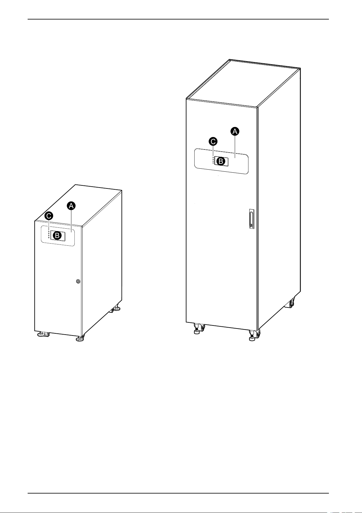
System Overview
A. User interface
B. Display interface
C. Status LEDs
10 990-5998D-001
System Overview For Internal and External Batteries
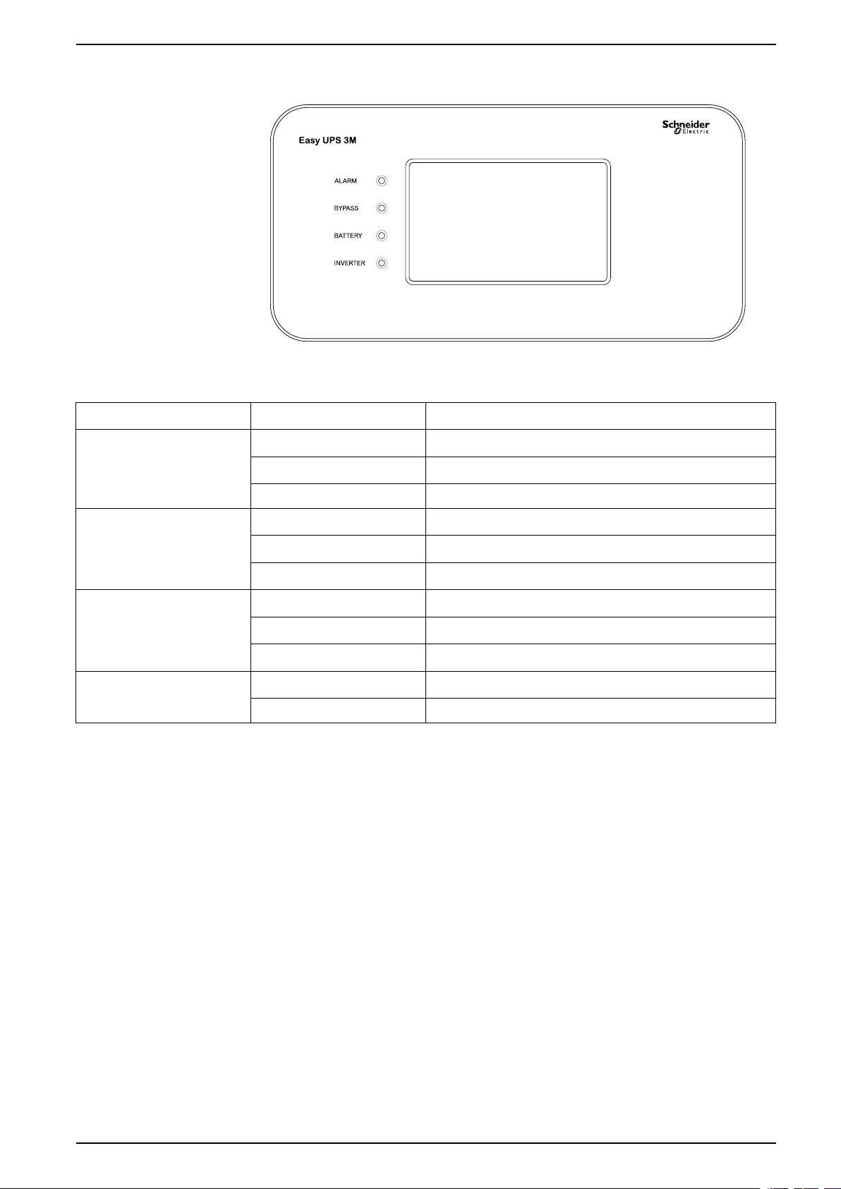
User Interface
Status LEDs
LED
ALARM
BYPASS Steady yellow
BATTERY
INVERTER
State
Steady red Critical alarm
Flashing red Warning alarm
Off
Flashing yellow There is an alarm condition on the bypass source
Off
Steady yellow
Flashing yellow The battery source is unavailable
Off
Steady green
Off Inverter off
Description
No alarm condition
The load is supplied by the bypass source
The load is not supplied by the bypass source
The load is supplied by the battery source
The load is not supplied by the battery source
Inverter on
990-5998D-001 11
For Internal and External Batteries System Overview
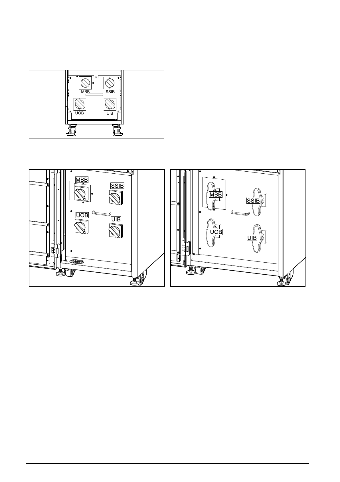
Location of Breakers and Switches
60-100 kVA 400 V/50 kVA 208 V UPS for External
Batteries
120-160 kVA 400 V/60–80 kVA 208 V UPS for
External Batteries
200 kVA 400 V/100 kVA 208 V UPS for External
Batteries
12 990-5998D-001
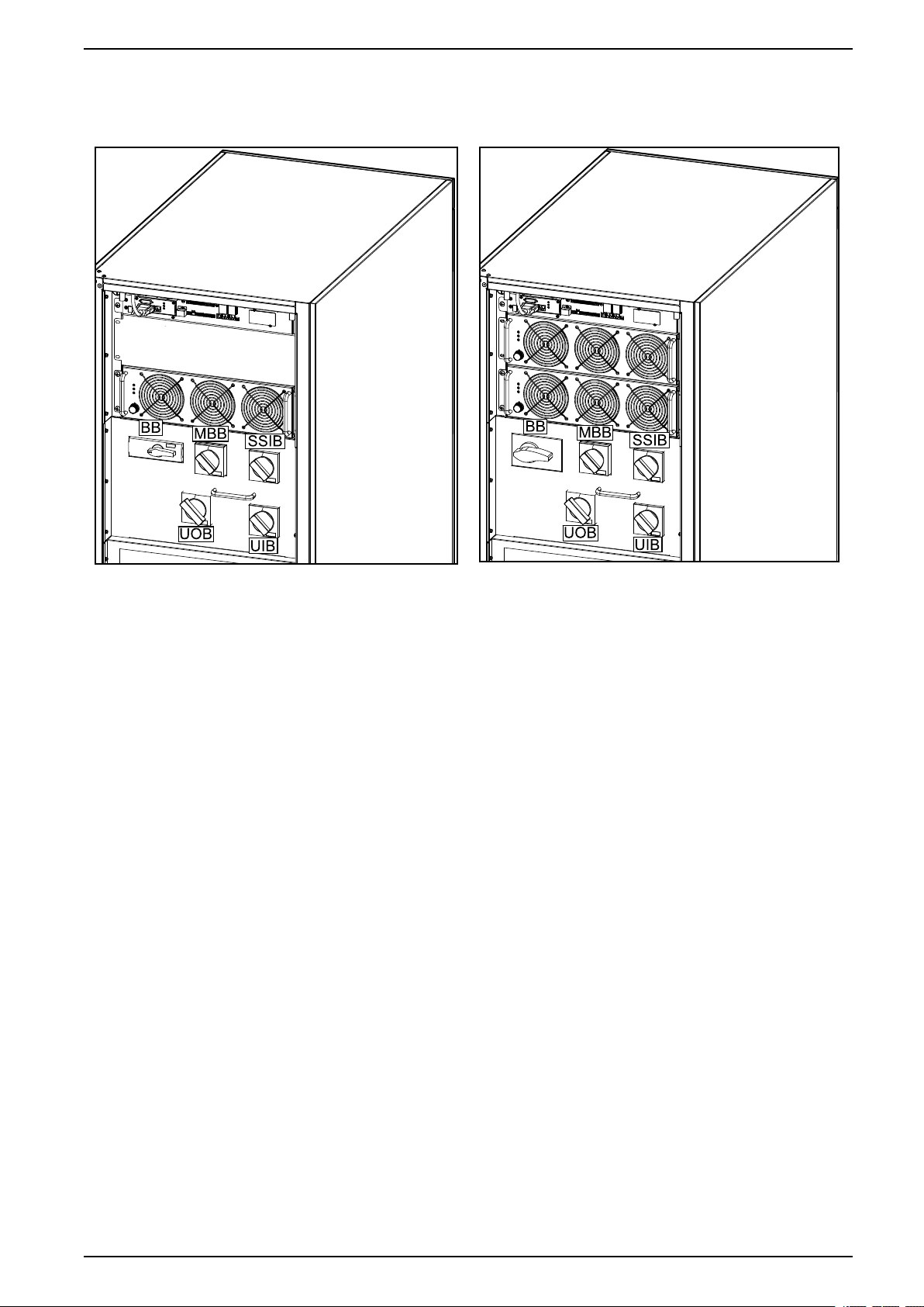
System Overview For Internal and External Batteries
Front View of the 60 kVA 400 V UPS for Internal
Batteries
Front View of the 80 kVA 400 V UPS for Internal
Batteries
990-5998D-001 13
For Internal and External Batteries System Overview
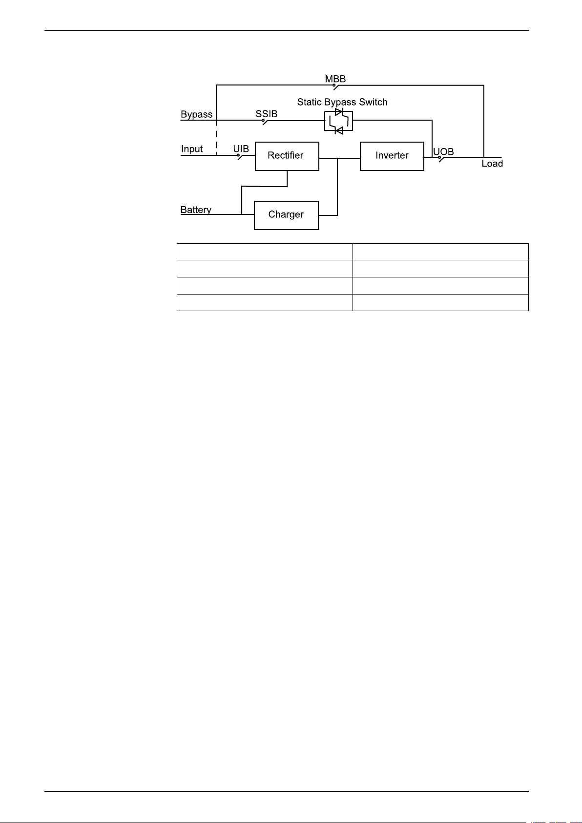
Overview of Single UPS
UIB Unit input switch
SSIB Static switch input switch
UOB Unit output switch
MBB Maintenance bypass switch
14 990-5998D-001
System Overview For Internal and External Batteries
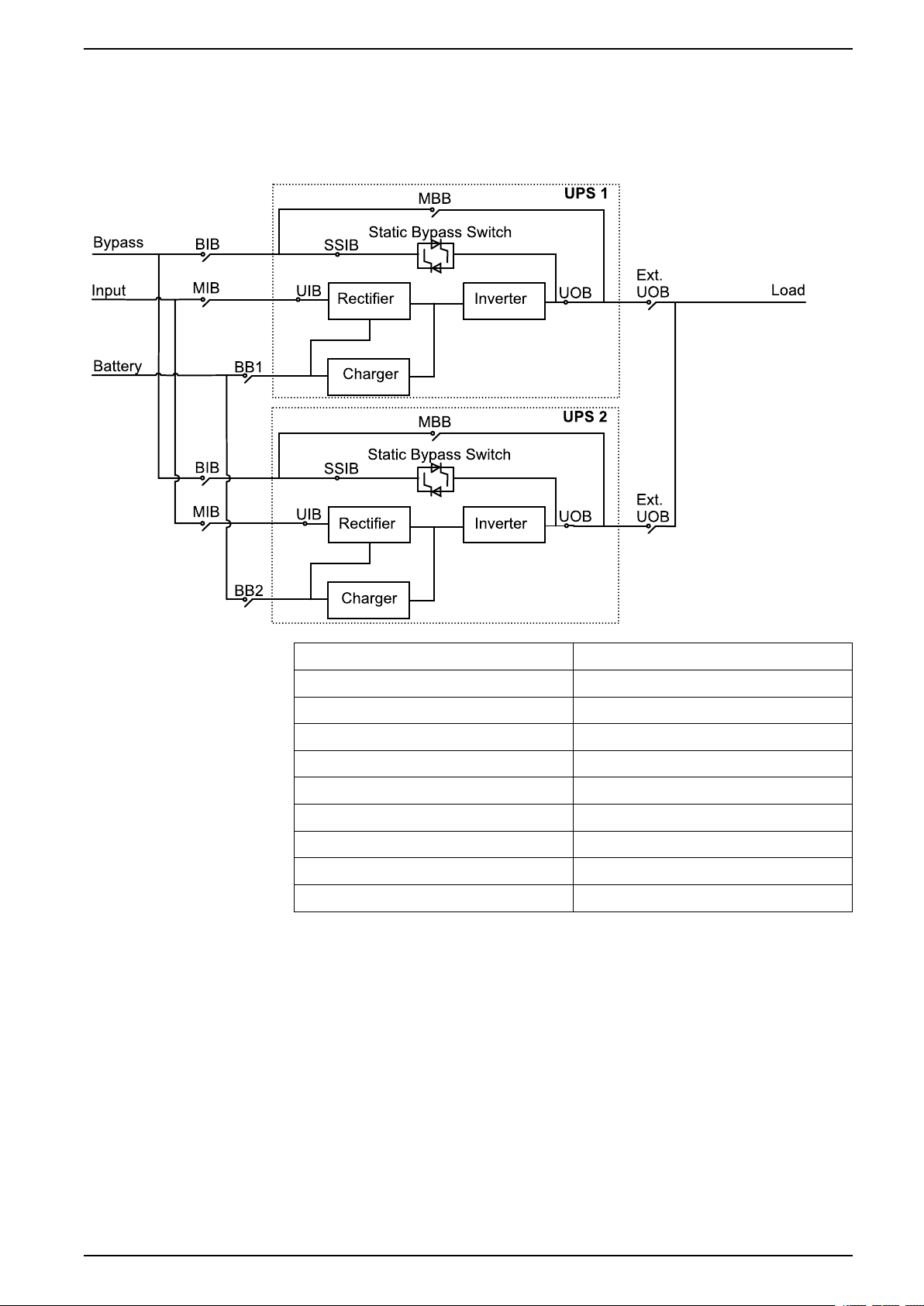
Overview of 1+1 Redundant Parallel System with Common Battery Bank
NOTE: Common battery banks are not supported in systems with internal
batteries.
MIB Mains input breaker
BIB Bypass input breaker
UIB Unit input switch
SSIB Static switch input switch
UOB Unit output switch
Ext. UOB External unit output breaker
MBB Maintenance bypass switch
Ext. MBB External maintenance bypass breaker
BB1 Battery breaker 1
BB2 Battery breaker 2
990-5998D-001 15
For Internal and External Batteries System Overview
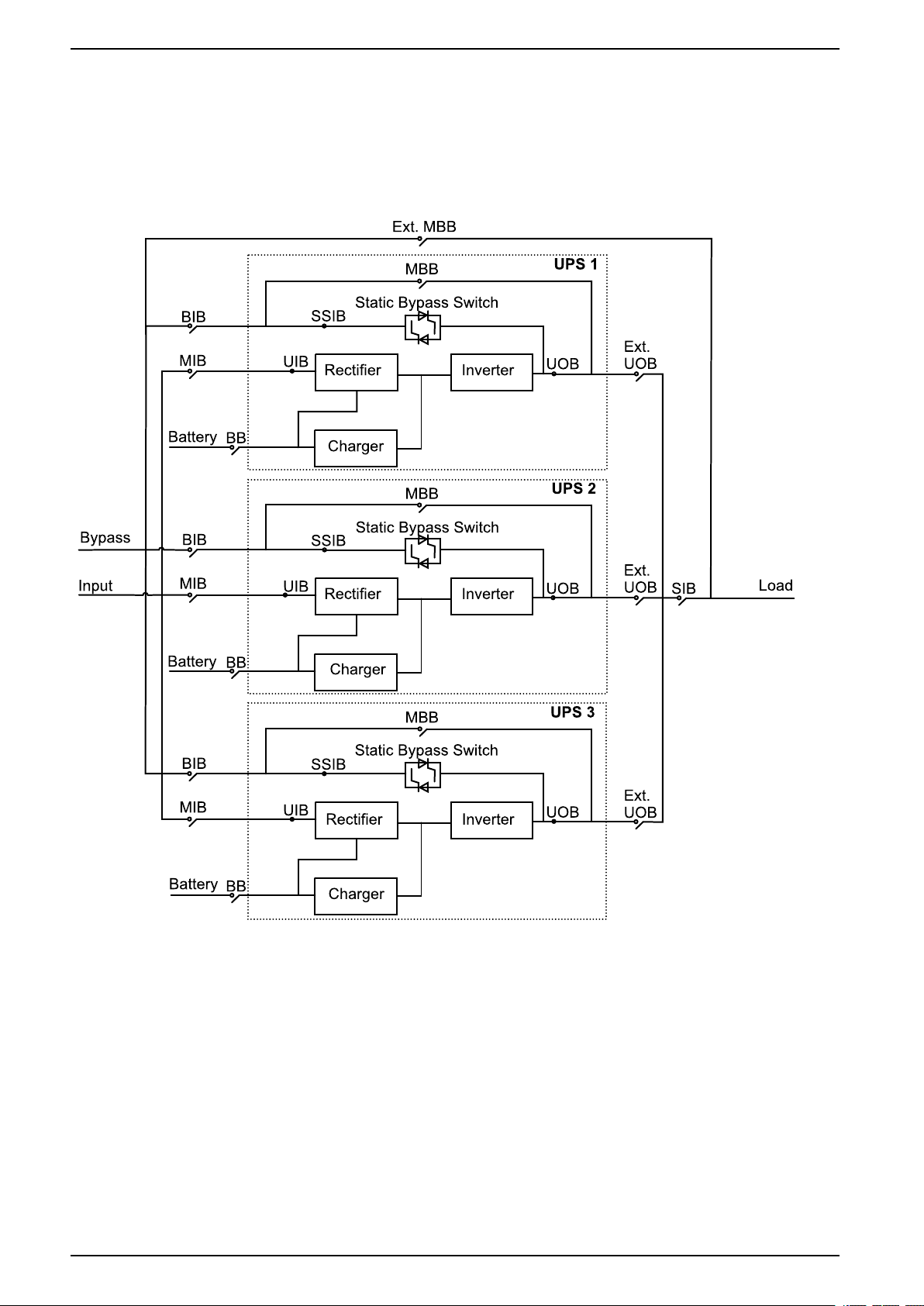
Overview of Parallel System
NOTE: In parallel systems with an external maintenance bypass breaker Ext.
MBB, the maintenance bypass breakers MBB must be padlocked in the open
position.
UPSs for External Batteries
16 990-5998D-001
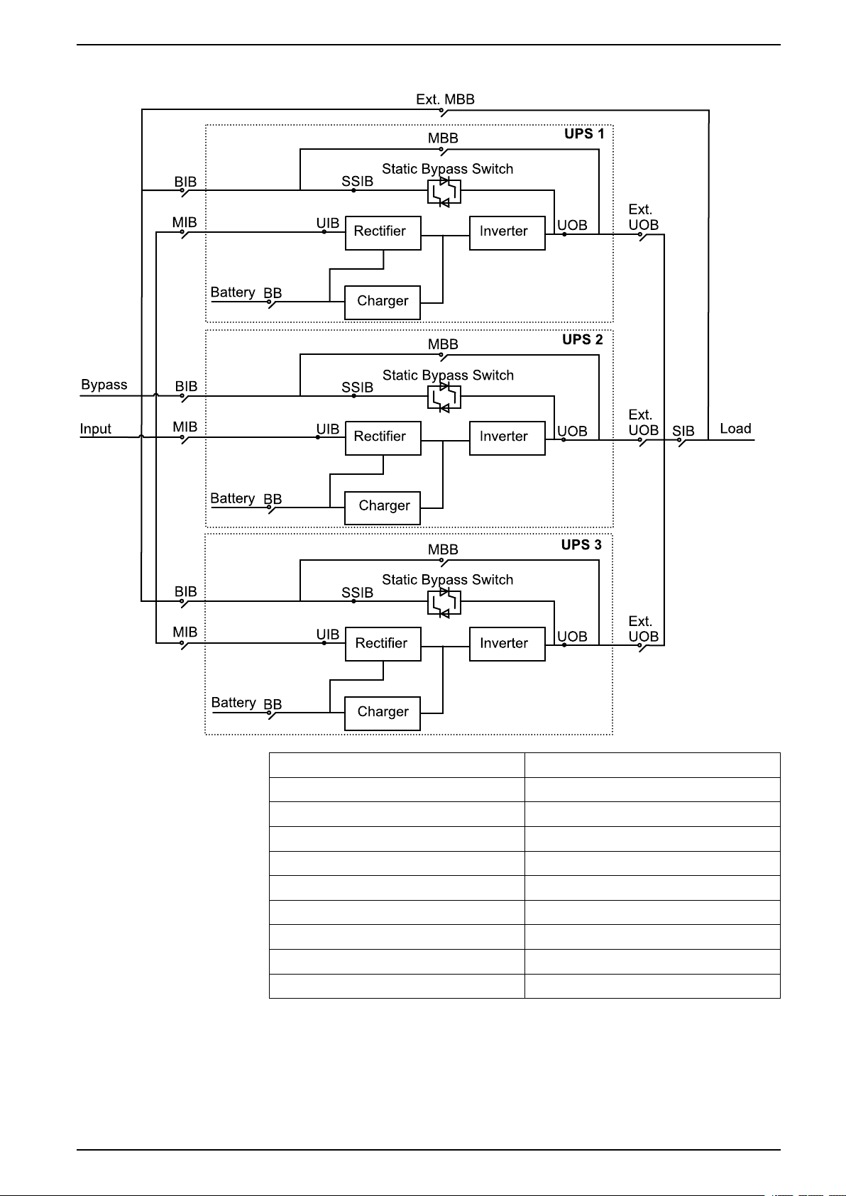
System Overview For Internal and External Batteries
UPSs for Internal Batteries
MIB Mains input breaker
BIB Bypass input breaker
UIB Unit input switch
SSIB Static switch input switch
UOB Unit output switch
Ext. UOB External unit output breaker
MBB Maintenance bypass switch
Ext. MBB External maintenance bypass breaker
SIB System isolation breaker
BB Battery breaker
990-5998D-001 17
For Internal and External Batteries Technical Data
Technical Data
Technical Data for 400 V Systems
Input Power Factor
The values are at a 400 V, 50 Hz linear load.
UPSs for Internal
Batteries
60 kVA 80 kVA 60 kVA 80 kVA 100 kVA 120 kVA 160 kVA 200 kVA
25% load 0.99 0.99 0.98 0.97 0.98 0.98 0.98 0.98
50% load 0.99 0.99 0.99 0.99 0.99 0.99 0.99 0.99
75% load 0.99 0.99 0.99 0.99 0.99 0.99 0.99 0.99
100% load 0.99 0.99 0.99 0.99 0.99 0.99 0.99 0.99
UPSs for External Batteries
Efficiency
Efficiency in Normal Mode
The values are at a 400 V, 50 Hz linear load.
UPSs for Internal
Batteries
60 kVA 80 kVA 60 kVA 80 kVA 100 kVA 120 kVA 160 kVA 200 kVA
25% load 95.3 94.8 95.5 94.7 95.3 95.3 95.6 95.5
50% load 95.6 95.5 95.8 95.5 95.6 95.6 95.8 95.6
75% load 95.3 95.3 95.4 95.3 95.2 95.2 95.2 95.1
100% load 94.8 94.9 94.8 94.9 94.8 94.6 94.5 94.5
UPSs for External Batteries
Efficiency in ECO Mode
UPSs for Internal
Batteries
60 kVA 80 kVA 60 kVA 80 kVA 100 kVA 120 kVA 160 kVA 200 kVA
25% load 98.9 98.8 98.9 98.8 99.0 99.0 99.0 99.0
50% load 99.1 98.9 99.1 99.0 99.2 99.2 99.1 99.1
75% load 99.0 98.9 99.0 98.9 99.0 99.0 99.0 99.0
100% load 99.1 99.0 99.1 99.0 99.1 99.0 99.0 99.0
UPSs for External Batteries
Efficiency in Battery Operation
UPSs for Internal
Batteries
60 kVA 80 kVA 60 kVA 80 kVA 100 kVA 120 kVA 160 kVA 200 kVA
25% load 95.0 94.5 94.9 95.0 95.1 94.8 95.1 94.7
50% load 95.8 95.3 95.7 95.4 95.7 95.5 95.5 95.2
75% load 95.7 95.3 95.4 95.2 95.4 95.3 95.1 94.9
100% load 95.3 95.1 95.1 94.8 94.9 95.0 94.7 94.4
UPSs for External Batteries
18 990-5998D-001
Technical Data For Internal and External Batteries
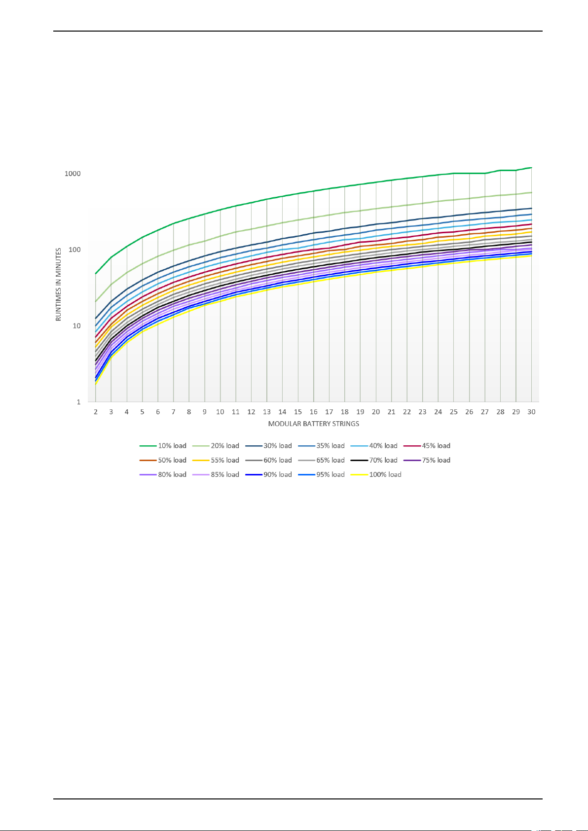
Battery Runtimes
Battery Runtimes for UPSs with Internal Batteries and Modular Battery Cabinets
60 kVA UPS
Battery runtimes are listed in minutes at various load percentages and are
estimated values based on battery manufacturer data for operation at 25 °C.
990-5998D-001 19

For Internal and External Batteries Technical Data
10% load (6 kVA)
20% load (12 kVA)
30% load (18 kVA)
35% load (21 kVA)
40% load (24 kVA)
45% load (27 kVA)
50% load (30 kVA)
55% load (33 kVA)
60% load (36 kVA)
65% load (39 kVA)
70% load (42 kVA)
75% load (45 kVA)
80% load (48 kVA)
85% load (51 kVA)
90% load (54 kVA)
95% load (57 kVA)
Number of modular
battery strings
2 48.5 21 12.5 10 8.4 7.1 6.1 5.3
3 79.5 35 21 17.5 14.5 12.5 10.5 9.6 8.4 7.5 6.7 6.1 5.5 5.0
4 110 50 30.5 25 21 18 16 14 12.5 11 10 9.2 8.4 7.7 7.1 6.5 6
5 145 65.5 40 33.5 28 24 21 18.5 16.5 15 13.5 12.5 11.5 10.5 9.7 9 8.4
6 180 82 50.5 42 35.5 30.5 26.5 23.5 21 19 17.5 16 14.5 13.5 12.5 11.5 10.5
7 220 98.5 61 50.5 43 37 32.5 29 26 23.5 21 19.5 18 16.5 15 14 13
8 255 115 71.5 59.5 50.5 43.5 38.5 34 30.5 27.5 25 23 21 19.5 19 17 15.5
9 295 130 82.5 68.5 58.5 50.5 44.5 39.5 35.5 32 29 26.5 24.5 22.5 21 19.5 18.5
10 335 150 94 78 66.5 57.5 50.5 45 40.5 36.5 33.5 30.5 28 26 24 22.5 21
11 375 170 105 87.5 74.5 64.5 57 50.5 45.5 41 37.5 34.5 31.5 29.5 27.5 25.5 24
12 415 185 115 97.5 83 72 63 56.5 50.5 46 42 38.5 35.5 32.5 30.5 28.5 26.5
13 460 205 125 105 91.5 79 69.5 62 56 50.5 46 42.5 39 36 33.5 31.5 29.5
14 500 225 140 115 100 86.5 76.5 68 61 55.5 50.5 46.5 43 39.5 37 34.5 32.5
15 545 245 150 125 105 94 83 74 66.5 60.5 55 50.5 46.5 43 40 37.5 35
16 590 265 165 135 115 100 89.5 80 72 65.5 59.5 54.5 50.5 47 43.5 40.5 38
17 630 285 175 145 125 105 96.5 86 77.5 70.5 64 59 54.5 50.5 47 44 41
18 675 305 190 155 135 115 100 92.5 83 75.5 68.5 63 58.5 54 50.5 47 44
19 720 325 200 165 140 125 110 98.5 88.5 80.5 73.5 67.5 62.5 58 54 50.5 47
20 765 345 215 180 150 130 115 105 94 85.5 78 72 66.5 61.5 57.5 53.5 50.5
21 815 365 225 190 160 140 120 110 100 91 83 76.5 70.5 65.5 61 57 53.5
22 860 385 240 200 170 145 130 115 105 96 87.5 80.5 74.5 69 64.5 60 56.5
23 905 405 255 210 180 155 135 120 110 100 92.5 85 78.5 73 68 63.5 59.5
24 955 430 265 220 190 165 145 130 115 105 97.5 89.5 83 77 71.5 67 63
25 1000 450 280 235 200 170 150 135 120 110 100 94 87 81 75.5 70.5 66
26 1000 470 295 245 210 180 160 140 125 115 105 99 91.5 84.5 79 74 69.5
27 1000 495 305 255 220 190 165 150 135 120 110 100 95.5 88.5 82.5 77.5 72.5
28 1100 515 320 265 230 195 175 155 140 125 115 105 100 92.5 86.5 81 76
29 1100 535 335 280 235 205 180 160 145 130 120 110 100 96.5 90 84.5 79
30 1200 560 350 290 245 215 190 170 150 135 125 115 105 100 94 88 82.5
100% load (60 kVA)
20 990-5998D-001
Technical Data For Internal and External Batteries
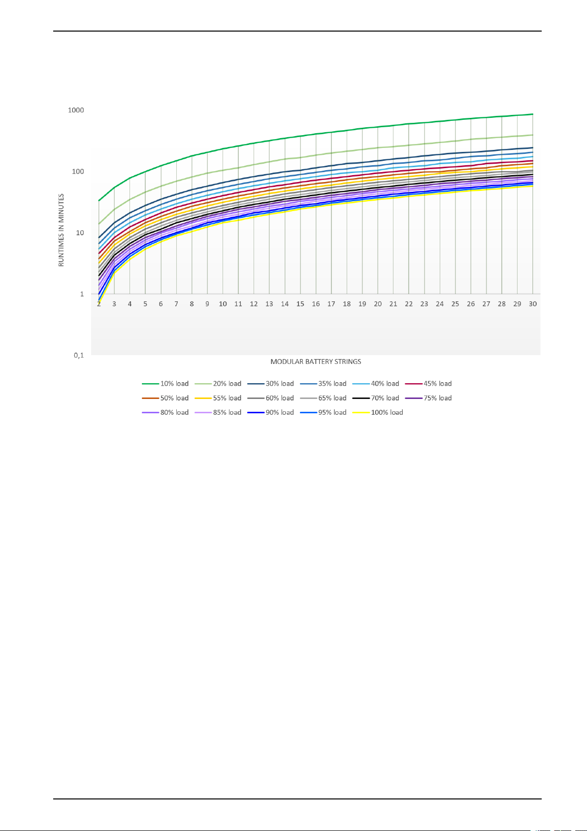
80 kVA UPS
Battery runtimes are listed in minutes at various load percentages and are
estimated values based on battery manufacturer data for operation at 25 °C.
990-5998D-001 21

For Internal and External Batteries Technical Data
10% load (8 kVA)
20% load (16 kVA)
30% load (24 kVA)
35% load (28 kVA)
40% load (32 kVA)
45% load (36 kVA)
50% load (40 kVA)
55% load (44 kVA)
60% load (48 kVA)
65% load (52 kVA)
70% load (56 kVA)
75% load (60 kVA)
80% load (64 kVA)
85% load (68 kVA)
90% load (72 kVA)
95% load (76 kVA)
Number of modular
battery strings
2 33.5 14 8.4 6.7 5.5
3 55 24 14.5 12 10 8.4 7.3 6.3 5.5
4 78 35 21 17.5 14.5 12.5 10.5 9.6 8.4 7.5 6.7 6 5.4
5 100 46 28 23 19.5 16.5 14.5 13 11.5 10 9.3 8.4 7.6 7 6.4 5.9 5.4
6 125 57.5 35.5 29 24.5 21 18.5 16.5 14.5 13 11.5 10.5 9.9 9.1 8.3 7.7 7.1
7 150 69.5 42.5 35.5 30 26 22.5 20 18 16 14.5 13 12 11 10 9.6 8.9
8 180 81.5 50.5 42 35.5 30.5 27 23.5 21 19 17 15.5 14.5 13 12 11.5 10.5
9 205 94 58 48.5 41 35.5 31 27.5 24.5 22 20 18.5 17 15.5 14.5 13.5 12.5
10 235 105 66 55 46.5 40.5 35.5 31.5 28 25.5 23 21 19.5 18 16.5 15.5 14.5
11 260 115 74.5 62 52.5 45.5 40 35.5 31.5 28.5 26 24 22 20 18.5 17.5 16
12 290 130 82.5 69 58.5 50.5 44.5 39.5 35.5 32 29 26.5 24.5 22.5 21 19.5 18
13 320 145 91 76 64.5 56 49 43.5 39 35.5 32 29.5 27 25 23 21.5 20
14 350 160 99.5 83 70.5 61 54 48 43 39 35.5 32.5 29.5 27.5 25.5 23.5 22
15 380 170 105 90 76.5 66.5 58.5 52 46.5 42 38.5 35 32.5 30 28 26 24.5
16 410 185 115 97.5 83 72 63.5 56.5 50.5 45.5 41.5 38 35 32.5 30 28 26.5
17 440 200 125 105 89 77.5 68 60.5 54.5 49.5 45 41 38 35 32.5 30.5 28.5
18 470 215 135 110 95.5 83 73 65 58.5 53 48 44 40.5 37.5 35 32.5 30.5
19 505 230 140 120 100 88.5 78 69.5 62.5 56.5 51.5 47 43.5 40.5 37.5 35 32.5
20 535 245 150 125 105 94 83 74 66.5 60 55 50.5 46.5 43 40 37.5 35
21 565 255 160 135 115 100 88 78.5 70.5 64 58 53.5 49 45.5 42.5 39.5 37
22 600 270 170 140 120 105 93.5 83 74.5 67.5 61.5 56.5 52 48.5 45 42 39.5
23 630 285 180 150 125 110 98.5 87.5 78.5 71.5 65 59.5 55 51 47.5 44.5 41.5
24 665 300 190 155 135 115 100 92.5 83 75 68.5 63 58 54 50 46.5 44
25 695 315 200 165 140 120 105 97 87 79 72 66 61 56.5 52.5 49 46
26 730 335 205 175 145 125 110 100 91.5 83 75.5 69.5 64 59.5 55 51.5 48.5
27 765 350 215 180 155 135 115 105 95.5 86.5 79 72.5 67 62 58 54 50.5
28 800 365 225 190 160 140 125 110 100 90.5 82.5 76 70 65 60.5 56.5 53
29 830 380 235 195 165 145 130 115 100 94.5 86 79 73 68 63 59 55.5
30 865 395 245 205 175 150 135 120 105 98.5 90 82.5 76 70.5 66 61.5 57.5
100% load (80 kVA)
22 990-5998D-001

Technical Data For Internal and External Batteries
Battery Runtimes for UPSs for External Batteries and Classic Battery Cabinets
Battery runtimes are listed in minutes and are estimated values based on battery
manufacturer data for operation at 25 °C.
Battery Runtimes for 60 and 80 kVA UPSs and Classic Battery Cabinets
60 kVA UPS 80 kVA UPS
Battery Solution 25% Load 50% Load 75% Load 100% Load 25% Load 50% Load 75% Load 100% Load
E3MCBC7A 49 19 10 5.9 33.5 12.5 5.9
E3MCBC7B 66.5 28 16.5 10.5 46.5 19 10.5 6.9
E3MCBC10A 88 39 23.5 16 63 27.5 16 10.5
E3MCBC10B 125 56 33.5 22.5 90.5 39 22.5 14.5
E3MCBC10C 140 63.5 38 26 100 44.5 26 17
E3MCBC10D 190 89 55.5 39 140 63,5 39 27
E3MCBC10E 280 125 79 55.5 200 91.5 55.5 38
2xE3MCBC7A 115 49.5 29 19 82.5 34 19 12
2xE3MCBC7B 150 67 40.5 28 105 47 28 19
Battery Runtimes for 100 and 120 kVA UPSs and Classic Battery Cabinets
100 kVA UPS 120 kVA UPS
Battery Solution 25% Load 50% Load 75% Load 100% Load 25% Load 50% Load 75% Load 100% Load
E3MCBC7A 24.5 8.5 19 5.9
E3MCBC7B 35.5 14 7.8 28 10.5 5.7
E3MCBC10A 48.5 20.5 11.5 7.5 39 16 8.9 5.4
E3MCBC10B 69.5 29 16 10 55.5 22.5 12 7.3
E3MCBC10C 78.5 33.5 19 12 63 26 14.5 8.9
E3MCBC10D 105 49 29.5 20.5 88 39 23.5 16
E3MCBC10E 155 70 42 28.5 125 55.5 33 22.5
2xE3MCBC7A 62.5 25 13.5 8.4 49 19 10 5.9
2xE3MCBC7B 83 35.5 21 14 66.5 28 16.5 10.5
2xE3MCBC10A 88 39 23.5 16
2xE3MCBC10B 125 55.5 33 22.5
2xE3MCBC10C 140 63.5 38 26
2xE3MCBC10D 190 88.5 55 39
2xE3MCBC10E 280 125 79 55.5
E3MCBC10A+
E3MCBC10D
E3MCBC10B+
E3MCBC10E
140 63.5 39 27
200 91 55.5 38.5
Battery Runtimes for 160 and 200 kVA UPSs and Classic Battery Cabinets
160 kVA UPS 200 kVA UPS
Battery Solution 25% Load 50% Load 75% Load 100% Load 25% Load 50% Load 75% Load 100% Load
E3MCBC7A 12 8.4
E3MCBC7B 19 7 14
E3MCBC10A 27 10.5 5.4 20.5 7.5
E3MCBC10B 38.5 14.5 7.4 28.5 10
E3MCBC10C 44 17.5 9 33 12 5.7
990-5998D-001 23

For Internal and External Batteries Technical Data
Battery Runtimes for 160 and 200 kVA UPSs and Classic Battery Cabinets (Continued)
160 kVA UPS 200 kVA UPS
Battery Solution 25% Load 50% Load 75% Load 100% Load 25% Load 50% Load 75% Load 100% Load
E3MCBC10D 63.5 27.5 16 10.5 48.5 20.5 11.5 7.4
E3MCBC10E 91 39 22.5 14.5 69 29 16 10
2xE3MCBC7A 33.5 12 5.9 24.5 8.5
2xE3MCBC7B 47 19 10.5 6.9 35 14 7.7
2xE3MCBC10A 63.5 27.5 16 10.5 48.5 20.5 11.5 7.4
2xE3MCBC10B 91 39 22.5 14.5 69 29 16 10
2xE3MCBC10C 100 44.5 26 17 78.5 33 19 12
2xE3MCBC10D 140 63.5 39 27 105 48.5 29.5 20
2xE3MCBC10E 200 91.5 55.5 38.5 155 69.5 42 28.5
E3MCBC10A+
E3MCBC10D
E3MCBC10B+
E3MCBC10E
100 45 27 18.5 78 34.5 20.5 13.5
145 64.5 38.5 26 110 49 28.5 19
Battery Gassing Rates for Modular Battery Cabinets and UPSs with Internal Batteries
The battery gassing rates are calculated based on:
• Gassing Rate at 2.4 V/cell (ft3 /hr) assuming 97% recombination efficiency
• Six cells per battery module
• Ten batteries per cartridge
Commercial Reference Description Typical cm³/hr (ml/hr)
E3SBTHU High performance battery module 12.67 (12.67)
E3SBTH4 High performance battery string 50.68 (50.68)
Electrolyte Values for Modular Battery Cabinet and UPSs with Internal Batteries
Commercial Reference Description Electrolyte Volume L (gal) Electrolyte Weight kg (lbs)
E3SBT4 Standard battery string 15.120 (4) 20 (44.4)
E3SBTH4 High performance battery string 13.320 (3.6) 17.6 (39.2)
24 990-5998D-001

Technical Data For Internal and External Batteries
Technical Data for 208 V Systems
Input Power Factor
The values are at a 208 V, 60 Hz linear load.
UPSs for External Batteries
50 kVA 60 kVA 80 kVA 100 kVA
25% load 0.99 0.99 0.99 0.99
50% load 0.99 0.99 0.99 0.99
75% load 0.99 0.99 0.99 0.99
100% load 0.99 0.99 0.99 0.99
Efficiency
Efficiency in Normal Mode
The values are at a 208 V, 60 Hz linear load.
UPSs for External Batteries
50 kVA 60 kVA 80 kVA 100 kVA
25% load 93.6 93.3 93.6 93.0
50% load 93.5 93.1 93.3 92.9
75% load 92.6 92.1 92.1 91.9
100% load 91.5 90.8 90.9 90.8
Efficiency in ECO Mode
UPSs for External Batteries
50 kVA 60 kVA 80 kVA 100 kVA
25% load 97.8 97.9 97.9 97.9
50% load 98.3 98.2 98.3 98.3
75% load 98.0 97.9 98.0 97.9
100% load 98.2 98.0 98.1 98.0
Efficiency in Battery Operation
UPSs for External Batteries
50 kVA 60 kVA 80 kVA 100 kVA
25% load 93.2 93.1 93.7 93.2
50% load 94.0 94.0 94.0 93.9
75% load 93.7 93.7 93.5 93.4
100% load 93.4 93.4 93.3 93.1
Battery Runtimes
Battery Runtimes for UPSs for External Batteries and Classic Battery Cabinets
Battery runtimes are listed in minutes and are estimated values based on battery
manufacturer data for operation at 25 °C.
990-5998D-001 25

For Internal and External Batteries Technical Data
Battery Runtimes for 50 and 60 kVA UPSs and Classic Battery Cabinets
50 kVA UPS 60 kVA UPS
Battery Solution 25% Load 50% Load 75% Load 100% Load 25% Load 50% Load 75% Load 100% Load
E3MCBC7A 61 24.5 13 8.1 48 18.5 9.9 5.7
E3MCBC7B 81.5 35 20.5 13.5 65 27.5 16 10.5
E3MCBC10A 105 48 29 20 86 38.5 23 15.5
E3MCBC10B 150 68.5 41 28 120 54.5 32.5 22
E3MCBC10C 170 77.5 47 32 140 62.5 37.5 25
E3MCBC10D 230 105 67 47.5 190 87 54 38
E3MCBC10E 340 155 96.5 67.5 275 125 77.5 54
2xE3MCBC7A 140 61.5 36 24 115 48.5 28 18.5
2xE3MCBC7B 185 82 50 34.5 150 66 39.5 27.5
2xE3MCBC10A 190 87 54 38
2xE3MCBC10B 275 125 77.5 54
2xE3MCBC10C 310 140 88 61.5
2xE3MCBC10D 410 190 120 86.5
2xE3MCBC10E 610 280 175 120
E3MCBC10A+
E3MCBC10D
E3MCBC10B+
E3MCBC10E
300 135 87 62
440 200 125 88.5
Battery Runtimes for 80 and 100 kVA UPSs and Classic Battery Cabinets
80 kVA UPS 100 kVA UPS
Battery Solution 25% Load 50% Load 75% Load 100% Load 25% Load 50% Load 75% Load 100% Load
E3MCBC7A 33 12 5.7 2.7 24 8.2 3.3 1
E3MCBC7B 46 19 10.5 6.7 34.5 13.5 7.5 4.5
E3MCBC10A 62 27 15.5 10 47 20 11.5 7.2
E3MCBC10B 89 38 22 14 67.5 28 15.5 9.9
E3MCBC10C 100 43.5 25.5 16.5 76.5 32.5 18.5 11.5
E3MCBC10D 135 62 38 26.5 105 47.5 29 20
E3MCBC10E 200 89.5 54.5 37.5 150 68 41 28
2xE3MCBC7A 81 33 18.5 11.5 60.5 24.5 13 8.1
2xE3MCBC7B 105 46 27.5 18.5 81 34.5 20.5 13.5
2xE3MCBC10A 135 62 38 26.5 105 47.5 29 20
2xE3MCBC10B 200 89.5 54.5 37.5 150 68 41 28
2xE3MCBC10C 225 100 62 43 170 77.5 47 32
2xE3MCBC10D 300 135 87 61.5 230 105 67 47
2xE3MCBC10E 440 200 125 88.5 340 155 96 67.5
E3MCBC10A+
E3MCBC10D
E3MCBC10B+
E3MCBC10E
215 99.5 62 44 165 77 47.5 33
315 140 89 62.5 245 110 68 47.5
26 990-5998D-001

Technical Data For Internal and External Batteries
Derating Due to Load Power Factor
End of Discharge Voltage
Compliance
Safety IEC 62040-1: 2008-06, 1st edition Uninterruptible Power Systems (UPS) - Part 1: General and safety requirements
EMC/EMI/RFI IEC 62040-2: 2005-10, 2nd edition Uninterruptible Power Systems (UPS) - Part 2: Electromagnetic compatibility
Performance IEC 62040-3: 2011-03, 2nd edition Uninterruptible Power Systems (UPS) - Part 3: Method of specifying the
Environmental IEC 62040-4: 2013-04, 1st edition Uninterruptible Power Systems (UPS) - Part 4: Environmental aspects –
Markings CE, RCM, EAC, WEEE
Transportation ISTA 2B
990-5998D-001 27
for UPS
IEC 62040-1: 2013-01, 1st edition amendment 1
(EMC) requirements
performance and test requirements
Requirements and reporting

For Internal and External Batteries Technical Data
Communication and Management
• User interface with status LEDs and display
• RS485
• SNMP (options)
• Dry contacts
• USB
28 990-5998D-001

Facility Planning for 400 V Systems For Internal and External Batteries
Facility Planning for 400 V Systems
Facility Planning for 60-80 kVA UPSs for Internal Batteries
Input Specifications
60 kVA 80 kVA
Voltage (V) 380 400 415 380 400 415
Connections L1, L2, L3, N, PE
Input voltage range (V) 342–477 at full load
Frequency range (Hz) 40–70
Nominal input current (A) 96 91 88 128 122 117
Maximum input current (A) 109 104 100 154 146 141
Input current limitation (A) 155 206
Total harmonic distortion (THDI) <3% for linear loads
Input power factor > 0.99
1
Maximum short circuit rating 10 kA RMS
Protection Fuse
Ramp-in 7 seconds
Bypass Specifications
60 kVA 80 kVA
Voltage (V) 380 400 415 380 400 415
Connections L1, L2, L3, N, PE
Overload capacity 110% for 60 minutes
Minimum bypass voltage (V) 266 280 291 266 280 291
Maximum bypass voltage (V) 475 480 477 475 480 477
Frequency (Hz) 50 or 60
Frequency range (%) ±1, ±2, ±4, ±5, ±10. Default is ±10 (user
Nominal bypass current (A) 91 87 83 122 115 111
Maximum short circuit rating 10 kA RMS
130% for 10 minutes
130–150% for 1 minute
selectable).
1. 150–342 V with a linear derating of the load to 30%.
990-5998D-001 29

For Internal and External Batteries Facility Planning for 400 V Systems
Output Specifications
60 kVA 80 kVA
Voltage (V) 380 400 415 380 400 415
Connections L1, L2, L3, N, PE
Overload capacity
Output voltage regulation ± 1%
Dynamic load response 20 milliseconds
Output power factor 1.0
Nominal output current (A) 91 87 83 122 115 111
2
110% for 60 minutes
125% for 10 minutes
150% for 1 minute
Total harmonic distortion (THDU) <3% at 100% linear load
Output frequency (Hz) 50 or 60
Slew rate (Hz/sec) Programmable: 0.5 to 2.0. Default is 0.5
Output performance classification (according to IEC/ EN62040-3) VFI-SS–111
Load power factor 0.5 leading to 0.5 lagging without
<5% at 100% non-linear load
derating
Battery Specifications
60 kVA 80 kVA
Charging power in % of output power 1–16% 1–24%
Maximum charging power (kW) 9600 19200
Nominal battery voltage (40 blocks) (VDC) ± 240
Nominal float voltage (40 blocks) (VDC) ± 270
End of discharge voltage (40 blocks) (VDC) ± 192
Battery current at full load and nominal battery voltage (A) 133 176
Battery current at full load and minimum battery voltage (A) 166 222
Temperature compensation (per cell) Programmable from 0–7 mV. Default is 0
Ripple current < 5% C10
mV
2. At 30 °C.
30 990-5998D-001

Facility Planning for 400 V Systems For Internal and External Batteries
Recommended Upstream Protection
NOTE: For local directives which require 4–pole circuit breakers: If neutral
conductor is expected to carry a high current, due to line-neutral non-linear
load, the circuit breaker must be rated according to expected neutral current.
60 kVA 80 kVA
Input Bypass Input Bypass
Breaker type Compact NSX160F
TM125D (LV430631)
In setting 125 100 160 160
Ir setting 125 100 160 144
Im setting 800 (fixed) 800 (fixed) 1250 (fixed) 1250 (fixed)
Compact NSX100F
TM100D (LV429630)
Compact NSX160F
TM160D (LV430630)
Compact NSX160F
TM160D (LV430630)
Recommended Cables Sizes
DANGER
HAZARD OF ELECTRIC SHOCK, EXPLOSION, OR ARC FLASH
All wiring must comply with all applicable national and/or electrical codes. The
maximum allowable cable size is 50 mm².
Failure to follow these instructions will result in death or serious injury.
Cable sizes in this manual are based on table B.52.5 of IEC 60364–5–52 with the
following assertions:
• 90 °C conductors
• An ambient temperature of 30 °C
• Use of copper conductors
• Installation method C
PE size is based on table 54.2 of IEC 60364–4–54.
If the ambient temperature is greater than 30 °C, larger conductors are to be used
in accordance with the correction factors of the IEC.
60 kVA UPS
Cable Size per Phase (AWG/
kcmil) (mm
Input 35 2x25 16
Bypass 25 16
Output 25 2x25 16
Battery 50 50 25
2
)
Neutral Cable Size (AWG/
kcmil) (mm2)
3
PE Cable Size (AWG/kcmil)
(mm
80 kVA UPS
Cable Size per Phase (AWG/
kcmil) (mm
Input 50 2x50 25
Bypass 50 25
2
)
Neutral Cable Size (AWG/
kcmil) (mm2)
3
PE Cable Size (AWG/kcmil)
(mm
2
)
2
)
3. Neutral conductor is sized to handle 1.73 times phase current in case of high harmonic content from non-linear loads. If non or less
harmonic currents are expected, neutral conductor can be sized accordingly but not less than the phase conductor.
990-5998D-001 31

For Internal and External Batteries Facility Planning for 400 V Systems
Cable Size per Phase (AWG/
kcmil) (mm
Output 50 2x50 25
Battery 2x50 2x50 50
2
)
Neutral Cable Size (AWG/
kcmil) (mm2)
4
Recommended Bolts and Cable Lugs
Cable Size (mm²) Bolt Size Cable Lug Type
16 M8 KST TLK16-8
25 M8 KST TLK25-8
35 M8 KST TLK35-8
50 M8 KST TLK50-8
Torque Specifications
Bolt Size Torque
M8 17.5 Nm
UPS Weights and Dimensions
PE Cable Size (AWG/kcmil)
2
(mm
)
UPS Weight kg (lbs) Height mm (in) Width mm (in) Depth mm (in)
60 kVA 311 1970 600 1000
80 kVA 339 1970 600 1000
UPS Shipping Weights and Dimensions
UPS Weight kg Height mm Width mm Depth mm
60 kVA 360 2102 750 1125
80 kVA 387 2102 750 1125
4. Neutral conductor is sized to handle 1.73 times phase current in case of high harmonic content from non-linear loads. If non or less
harmonic currents are expected, neutral conductor can be sized accordingly but not less than the phase conductor.
32 990-5998D-001

Facility Planning for 400 V Systems For Internal and External Batteries
Clearance
NOTE: Clearance dimensions are published for airflow and service access
only. Consult with the local safety codes and standards for additional
requirements in your local area.
Environmental
Operation Storage
Temperature 0 °C to 40 °C -15 °C to 40 °C for systems with batteries
Relative humidity 0–95% non-condensing
Elevation derating according to
IEC 62040–3
Audible noise <65 dBA at full load and an ambient
Protection class IP20 (dust filter as standard)
Color RAL 9003
Power derating factor:
0–1500 m: 1.000
1500–2000 m: 0.975
temperature of 30 °C
5
-25 °C to 55 °C for systems without batteries
< 15000 m above sea level (or in an
environment with equivalent air pressure)
Heat Dissipation
60 kVA 80 kVA
W BTU/hr W BTU/hr
Normal operation 3084 10523 4296 14659
Battery operation 2958 10093 4352 14850
ECO mode 540 1843 696 2375
5. According to ISO 3746.
990-5998D-001 33

For Internal and External Batteries Facility Planning for 400 V Systems
Facility Planning for 60-100 kVA UPSs for External Batteries
Input Specifications
60 kVA 80 kVA 100 kVA
Voltage (V) 380 400 415 380 400 415 380 400 415
Connections L1, L2, L3, N, PE
Input voltage range (V) 342–477 at full load
Frequency range (Hz) 40–70
Nominal input current (A) 96 91 88 128 122 117 160 152 146
Maximum input current (A) 109 104 100 154 146 141 186 177 170
Input current limitation (A) 155 206 258
Total harmonic distortion (THDI) <3% for linear loads
Input power factor > 0.99
Maximum short circuit rating 10 kA RMS
Protection Fuse
Ramp-in 7 seconds
6
Bypass Specifications
60 kVA 80 kVA 100 kVA
Voltage (V) 380 400 415 380 400 415 380 400 415
Connections L1, L2, L3, N, PE
Overload capacity 110% for 60 minutes
Minimum bypass voltage (V) 266 280 291 266 280 291 266 280 291
Maximum bypass voltage (V) 475 480 477 475 480 477 475 480 477
Frequency (Hz) 50 or 60
Frequency range (%) ±1, ±2, ±4, ±5, ±10. Default is ±10 (user selectable).
Nominal bypass current (A) 91 87 83 122 115 111 152 144 139
Maximum short circuit rating 10 kA RMS
130% for 10 minutes
130–150% for 1 minute
6. 150–342 V with a linear derating of the load to 30%.
34 990-5998D-001

Facility Planning for 400 V Systems For Internal and External Batteries
Output Specifications
60 kVA 80 kVA 100 kVA
Voltage (V) 380 400 415 380 400 415 380 400 415
Connections L1, L2, L3, N, PE
Overload capacity
Output voltage regulation ± 1%
Dynamic load response 20 milliseconds
Output power factor 1.0
Nominal output current (A) 91 87 83 122 115 111 152 144 139
7
110% for 60 minutes
125% for 10 minutes
150% for 1 minute
Total harmonic distortion (THDU) <3% at 100% linear load
Output frequency (Hz) 50 or 60
Slew rate (Hz/sec) Programmable: 0.5 to 2.0. Default is 0.5
Output performance classification (according to IEC/ EN62040-3) VFI-SS–111
Load power factor 0.5 leading to 0.5 lagging without derating
<5% at 100% non-linear load
Battery Specifications
60 kVA 80 kVA 100 kVA
Charging power in % of output power 1–20% 1–30% 1–24%
Maximum charging power (W) 12000 24000 24000
Nominal battery voltage (32–50 blocks
Nominal float voltage (32–50 blocks
End of discharge voltage (32–50 blocks) (VDC) ± 153.6 to ± 240
Battery current at full load and nominal battery voltage (36–50 blocks) (A) 147–105 196–140 245–175
Battery current at full load and minimum battery voltage (36–50 blocks)
(A)
Temperature compensation (per cell)
8
) (VDC) ± 192 to ± 300
8
) (VDC) ± 215.5 to ± 337.5
185–132 246–176 308–221
9
Programmable from 0–7 mV. Default is 0 mV
Ripple current < 5% C10
Recommended Upstream Protection
NOTE: For local directives which require 4–pole circuit breakers: If neutral
conductor is expected to carry a high current, due to line-neutral non-linear
load, the circuit breaker must be rated according to expected neutral current.
60 kW 80 kW 100 kW
Input Bypass Input Bypass Input Bypass
Breaker type Compact
NSX160F
TM125D
(LV430631)
In setting 125 100 160 160 200 160
7. At 30 °C.
8. 32–34 blocks are only possible when the load is <90%.
9. If the temperature is above 25 °C. If the temperature is below 25 °C, no compensation is needed.
990-5998D-001 35
Compact
NSX100F
TM100D
(LV429630)
Compact
NSX160F
TM160D
(LV430630)
Compact
NSX160F
TM160D
(LV430630)
Compact
NSX250F
TM200D
(LV431631)
Compact
NSX160F
TM160D
(LV430630)

For Internal and External Batteries Facility Planning for 400 V Systems
60 kW 80 kW 100 kW
Input Bypass Input Bypass Input Bypass
Ir setting 125 100 160 144 200 160
Im setting 800 (fixed) 800 (fixed) 1250 (fixed) 1250 (fixed) 1000 1250 (fixed)
Recommended Cable Sizes
DANGER
HAZARD OF ELECTRIC SHOCK, EXPLOSION, OR ARC FLASH
All wiring must comply with all applicable national and/or electrical codes. The
maximum allowable cable size is 70 mm².
Failure to follow these instructions will result in death or serious injury.
Cable sizes in this manual are based on table B.52.5 of IEC 60364–5–52 with the
following assertions:
• 90 °C conductors
• An ambient temperature of 30 °C
• Use of copper conductors
• Installation method C
PE size is based on table 54.2 of IEC 60364–4–54.
If the ambient temperature is greater than 30 °C, larger conductors are to be used
in accordance with the correction factors of the IEC.
60 kVA UPS
Cable Size per Phase (mm²) Neutral10Cable Size (mm²) PE Cable Size (mm²)
Input 35 2x25 16
Bypass 25 16
Output 25 2x25 16
Battery 50 50 25
80 kVA UPS
Cable Size per Phase (mm²) Neutral10Cable Size (mm²) PE Cable Size (mm²)
Input 50 2x50 25
Bypass 50 25
Output 50 2x50 25
Battery 2x50 2x50 50
100 kVA UPS
Cable Size per Phase (mm²) Neutral10Cable Size (mm²) PE Cable Size (mm²)
Input 70 2x70 35
Bypass 70 35
10. Neutral conductor is sized to handle 1.73 times phase current in case of high harmonic content from non-linear loads. If non or less
harmonic currents are expected, neutral conductor can be sized accordingly but not less than the phase conductor.
36 990-5998D-001

Facility Planning for 400 V Systems For Internal and External Batteries
Cable Size per Phase (mm²) Neutral11Cable Size (mm²) PE Cable Size (mm²)
Output 70 2x70 35
Battery 2x70 2x70 70
Recommended Bolts and Cable Lugs
Cable Size (mm²) Bolt Size Cable Lug Type
16 M8 KST TLK16-8
25 M8 KST TLK25-8
35 M8 KST TLK35-8
50 M8 KST TLK50-8
70 M8 KST TL70-8
UPS Weights and Dimensions
UPS Weight kg Height mm Width mm Depth mm
60 kVA 400 V 109 915 360 850
80 kVA 400 V 140 915 360 850
100 kVA 400 V/50 kVA
208 V
145 915 360 850
UPS Shipping Weights and Dimensions
UPS Weight kg Height mm Width mm Depth mm
60 kVA 400 V 133 1140 475 965
80 kVA 400 V 164 1140 475 965
100 kVA 400 V/50 kVA
208 V
169 1140 475 965
11. Neutral conductor is sized to handle 1.73 times phase current in case of high harmonic content from non-linear loads. If non or less
harmonic currents are expected, neutral conductor can be sized accordingly but not less than the phase conductor.
990-5998D-001 37

For Internal and External Batteries Facility Planning for 400 V Systems
Clearance
NOTE: Clearance dimensions are published for airflow and service access
only. Consult with the local safety codes and standards for additional
requirements in your local area.
Option A
Option B
NOTE: If the UPS is installed without side access,
the length of the cables connected to the UPS
must allow for rolling out the UPS.
Environmental
Operation Storage
Temperature 0 °C to 40 °C -15 °C to 40 °C for systems with batteries
Relative humidity 0–95% non-condensing
Elevation derating according to
IEC 62040–3
Audible noise <65 dBA at full load and an ambient
Protection class IP20 (dust filter as standard)
Color RAL 9003
Power derating factor:
0–1500 m: 1.000
1500–2000 m: 0.975
temperature of 30 °C
12
-25 °C to 55 °C for systems without batteries
< 15000 m above sea level (or in an
environment with equivalent air pressure)
12. According to ISO 3746.
38 990-5998D-001

Facility Planning for 400 V Systems For Internal and External Batteries
Heat Dissipation
60 kVA 80 kVA 100 kVA
W BTU/hr W BTU/hr W BTU/hr
Normal mode 3084 10523 4296 14659 5500 18767
Battery mode 2958 10093 4352 14850 5520 18835
ECO mode 540 1843 696 2375 1020 3480
990-5998D-001 39

For Internal and External Batteries Facility Planning for 400 V Systems
Facility Planning for 120-200 kVA UPSs for External Batteries
Input Specifications
120 kVA 160 kVA 200 kVA
Voltage (V) 380 400 415 380 400 415 380 400 415
Connections L1, L2, L3, N, PE
Input voltage range (V) 342-477 at full load
Frequency range (Hz) 40–70
Nominal input current (A) 192 182 176 256 243 234 320 304 293
Maximum input current (A) 218 207 200 262 262 262 336 336 336
Input current limitation (A) 309 412 515
Total harmonic distortion (THDI) <3% for linear loads
Input power factor > 0.99
Maximum short circuit rating 10 kA RMS
Protection Fuse
Ramp-in 7 seconds
13
Bypass Specifications
120 kVA 160 kVA 200 kVA
Voltage (V) 380 400 415 380 400 415 380 400 415
Connections L1, L2, L3, N, PE
Overload capacity 110% for 60 minutes
Minimum bypass voltage (V) 266 280 291 266 280 291 266 280 291
Maximum bypass voltage (V) 475 480 477 475 480 477 475 480 477
Frequency (Hz) 50 or 60
Frequency range (%) ±1, ±2, ±4, ±5, ±10. Default is ±10 (user selectable).
Nominal bypass current (A) 184 175 169 246 233 225 307 292 281
Maximum short circuit rating 10 kA RMS
130% for 10 minutes
130-150% for 1 minute
13. 150-342 V with a linear derating of the load to 30%.
40 990-5998D-001

Facility Planning for 400 V Systems For Internal and External Batteries
Output Specifications
120 kVA 160 kVA 200 kVA
Voltage (V) 380 400 415 380 400 415 380 400 415
Connections L1, L2, L3, N, PE
Overload capacity
Output voltage regulation ± 1%
Dynamic load response 20 milliseconds
Output power factor 1.0
Nominal output current (A) 182 173 167 243 231 223 304 289 278
14
110% for 60 minutes
125% for 10 minutes
150% for 1 minute
Total harmonic distortion (THDU) <3% at 100% linear load
Output frequency (Hz) 50 or 60
Slew rate (Hz/sec) Programmable: 0.5 to 2.0. Default is 0.5
Output performance classification (according to IEC/ EN62040-3) VFI-SS–111
Load power factor 0.5 leading to 0.5 lagging without derating
<5% at 100% non-linear load
Battery Specifications
120 kVA 160 kVA 200 kVA
Charging power in % of output power 1-20% 1-22.5% 1-24%
Maximum charging power (W) 24000 36000 48000
Nominal battery voltage (32-50 blocks
Nominal float voltage (32-50 blocks
End of discharge voltage (32-50 blocks) (VDC) ± 153.6 to ± 240
Battery current at full load and nominal battery voltage (36-50 blocks) (A) 294-211 392-281 490-351
Battery current at full load and minimum battery voltage (36-50 blocks)
(A)
Temperature compensation (per cell)
15
) (VDC) ± 192 to ± 300
15
) (VDC) ± 215.5 to ± 337.5
369-265 493-353 616-441
16
Programmable from 0-7 mV. Default is 0 mV
Ripple current < 5% C10
Recommended Upstream Protection
NOTE: For local directives which require 4-pole circuit breakers: If neutral
conductor is expected to carry a high current, due to line-neutral non-linear
load, the circuit breaker must be rated according to expected neutral current.
120 kVA 160 kVA 200 kVA
Input Bypass Input Bypass Input Bypass
Breaker type Compact
NSX250F
Micrologic 2.2
(LV431770)
In setting 250 250 360 320 400 400
14. At 30 °C.
15. 32-34 blocks are only possible when the load is <90%.
16. If the temperature is above 25 °C. If the temperature is below 25 °C, no compensation is needed.
990-5998D-001 41
Compact
NSX250F
Micrologic 2.2
(LV431770)
Compact
NSX400F
Micrologic 2.3
(LV432676)
Compact
NSX400F
Micrologic 2.3
(LV432676)
Compact
NSX400F
Micrologic 2.3
(LV432676)
Compact
NSX400F
Micrologic 2.3
(LV432676)

For Internal and External Batteries Facility Planning for 400 V Systems
120 kVA 160 kVA 200 kVA
Input Bypass Input Bypass Input Bypass
Ir setting 0.97 0.95 0.9 0.99 1 0.99
Im setting 1.5-10 1.5-10 1.5-10 1.5-10 1.5-10 1.5-10
Recommended Cable Sizes
DANGER
HAZARD OF ELECTRIC SHOCK, EXPLOSION, OR ARC FLASH
All wiring must comply with all applicable national and/or electrical codes. The
maximum allowable cable size is 150 mm².
Failure to follow these instructions will result in death or serious injury.
Cable sizes in this manual are based on table B.52.5 of IEC 60364–5–52 with the
following assertions:
• 90 °C conductors
• An ambient temperature of 30 °C
• Use of copper conductors
• Installation method C
PE size is based on table 54.2 of IEC 60364–4–54.
If the ambient temperature is greater than 30 °C, larger conductors are to be used
in accordance with the correction factors of the IEC.
120 kVA UPS
Cable Size per Phase (mm²) Neutral17Cable Size (mm²) PE Cable Size (mm²)
Input 95 120 50
Bypass 95 120 50
Output 95 120 50
Battery 2x70 2x70 70
160 kVA UPS
Cable Size per Phase (mm²) Neutral17Cable Size (mm²) PE Cable Size (mm²)
Input 120 120 70
Bypass 120 120 70
Output 120 120 70
Battery 2x95 2x95 95
200 kVA UPS
Cable Size per Phase (mm²) Neutral17Cable Size (mm²) PE Cable Size (mm²)
Input 150 150 95
Bypass 150 150 95
17. Neutral conductor is sized to handle 1.73 times phase current in case of high harmonic content from non-linear loads. If non or less
harmonic currents are expected, neutral conductor can be sized accordingly but not less than the phase conductor.
42 990-5998D-001

Facility Planning for 400 V Systems For Internal and External Batteries
Cable Size per Phase (mm²) Neutral18Cable Size (mm²) PE Cable Size (mm²)
Output 150 150 95
Battery 2x120 2x120 120
Recommended Bolts and Cable Lugs
Cable Size (mm²) Bolt Size Cable Lug Type
50 M8 KST TLK50-8
70 M10 KST TLK70-10
95 M10 KST TLK95–10
120 M10 KST TLK120–10
150 M10 KST TLK150–10
UPS Weights and Dimensions
UPS Weight kg Height mm Width mm Depth mm
120 kVA 400 V/60 kVA
208 V
160 kVA 400 V/80 kVA
208 V
200 kVA 400 V/100 kVA
208 V
193 1300 500 850
227 1300 500 850
304 1300 600 850
UPS Shipping Weights and Dimensions
UPS Weight kg Height mm Width mm Depth mm
120 kVA 400 V/60 kVA
208 V
160 kVA 400 V/80 kVA
208 V
200 kVA 400 V/100 kVA
208 V
223 1500 625 975
257 1500 625 975
338 1500 725 975
18. Neutral conductor is sized to handle 1.73 times phase current in case of high harmonic content from non-linear loads. If non or less
harmonic currents are expected, neutral conductor can be sized accordingly but not less than the phase conductor.
990-5998D-001 43

For Internal and External Batteries Facility Planning for 400 V Systems
Clearance
NOTE: Clearance dimensions are published for airflow and service access
only. Consult with the local safety codes and standards for additional
requirements in your local area.
Environmental
Operation Storage
Temperature 0 °C to 40 °C -15 °C to 40 °C for systems with batteries
Relative humidity 0–95% non-condensing
Elevation derating according to
IEC 62040-3
Audible noise <70 dBA at full load and an ambient
Protection class IP20 (air filter as standard)
Color RAL 9003
Power derating factor:
0-1500 m: 1.000
1500-2000 m: 0.975
temperature of 30 °C
19
-25 °C to 55 °C for systems without batteries
< 15000 m above sea level (or in an
environment with equivalent air pressure)
Heat Dissipation
120 kVA 160 kVA 200 kVA
W BTU/hr W BTU/hr W BTU/hr
Normal mode 6000 20473 8000 27297 10000 34121
Battery mode 6000 20473 8000 27297 10000 34121
ECO mode 1020 3480 1600 5459 2000 6824
19. According to ISO 3746.
44 990-5998D-001

Facility Planning for 208 V Systems For Internal and External Batteries
Facility Planning for 208 V Systems
Facility Planning for 50 kVA UPSs
Input Specifications
50 kVA
Voltage (V) 200 208 220
Connections L1, L2, L3, N, PE
Input voltage range (V) 180–272 at full load
Frequency range (Hz) 40–70
Nominal input current (A) 159 152 143
Maximum input current (A) 170 163 154
Input current limitation (A) 254
Total harmonic distortion (THDI) <3% for linear loads
Input power factor > 0.99
20
Maximum short circuit rating 10 kA RMS
Protection Fuse
Ramp-in 12 seconds
Bypass Specifications
50 kVA
Voltage (V) 200 208 220
Connections L1, L2, L3, N, PE
Overload capacity 110% for 60 minutes
Minimum bypass voltage (V) 140 146 154
Maximum bypass voltage (V) 250 260 275
Frequency (Hz) 50 or 60
Frequency range (%) ±1, ±2, ±4, ±5, ±10. Default is ±10 (user selectable).
Nominal bypass current (A) 147 141 133
Maximum short circuit rating 10 kA RMS
130% for 10 minutes
130–150% for 1 minute
Output Specifications
50 kVA
Voltage (V) 200 208 220
Connections L1, L2, L3, N, PE
Overload capacity
Output voltage regulation ± 1%
Dynamic load response 20 milliseconds
20. 126–180 V with a linear derating of the load to 30%.
21. At 30 °C.
990-5998D-001 45
21
110% for 60 minutes
125% for 10 minutes
150% for 1 minute

For Internal and External Batteries Facility Planning for 208 V Systems
50 kVA
Voltage (V) 200 208 220
Output power factor 1.0
Nominal output current (A) 144 139 131
Total harmonic distortion
(THDU)
Output frequency (Hz) 50 or 60
Slew rate (Hz/sec) Programmable: 0.5 to 2.0. Default is 0.5
Output performance
classification (according to IEC/
EN62040-3)
Load power factor 0.5 leading to 0.5 lagging without derating
<3% at 100% linear load
<5% at 100% non-linear load
VFI-SS–111
Battery Specifications
50 kVA
Charging power in % of output power 1-38.4%
Maximum charging power (W) 19200
Nominal battery voltage (32-40 blocks) (VDC) ± 192 to ± 240
Nominal float voltage (32-40 blocks) (VDC) ± 215.5 to ± 270
End of discharge voltage (32-40 blocks) (VDC) ± 153.6 to ± 192
Battery current at full load and nominal battery voltage (32-40
blocks) (A)
Battery current at full load and minimum battery voltage (32-40
blocks) (A)
Temperature compensation (per cell)
22
140-112
175-140
Programmable from 0-7 mV. Default is 0 mV
Ripple current < 5% C10
22. If the temperature is above 25 °C. If the temperature is below 25 °C, no compensation is needed.
46 990-5998D-001

Facility Planning for 208 V Systems For Internal and External Batteries
Recommended Upstream Protection
NOTE: For local directives which require 4–pole circuit breakers: If neutral
conductor is expected to carry a high current, due to line-neutral non-linear
load, the circuit breaker must be rated according to expected neutral current.
50 kW
Input Bypass
Breaker type Compact NSX250F TM200D (LV431631) Compact NSX160F TM160D (LV430630)
In setting 200 160
Ir setting 200 160
Im setting 1000 1250 (fixed)
Recommended Cable Sizes
DANGER
HAZARD OF ELECTRIC SHOCK, EXPLOSION, OR ARC FLASH
All wiring must comply with all applicable national and/or electrical codes. The
maximum allowable cable size is 70 mm².
Failure to follow these instructions will result in death or serious injury.
Cable sizes in this manual are based on table B.52.5 of IEC 60364–5–52 with the
following assertions:
• 90 °C conductors
• An ambient temperature of 30 °C
• Use of copper conductors
• Installation method C
PE size is based on table 54.2 of IEC 60364–4–54.
If the ambient temperature is greater than 30 °C, larger conductors are to be used
in accordance with the correction factors of the IEC.
50 kVA UPS
Cable Size per Phase (mm²) Neutral23Cable Size (mm²) PE Cable Size (mm²)
Input 70 2x70 35
Bypass 70 35
Output 70 2x70 35
Battery 70 70 35
UPS Weights and Dimensions
UPS Weight kg Height mm Width mm Depth mm
60 kVA 400 V 109 915 360 850
80 kVA 400 V 140 915 360 850
100 kVA 400 V/50 kVA
208 V
23. Neutral conductor is sized to handle 1.73 times phase current in case of high harmonic content from non-linear loads. If non or less
harmonic currents are expected, neutral conductor can be sized accordingly but not less than the phase conductor.
990-5998D-001 47
145 915 360 850

For Internal and External Batteries Facility Planning for 208 V Systems
UPS Shipping Weights and Dimensions
UPS Weight kg Height mm Width mm Depth mm
60 kVA 400 V 133 1140 475 965
80 kVA 400 V 164 1140 475 965
100 kVA 400 V/50 kVA
208 V
169 1140 475 965
Clearance
NOTE: Clearance dimensions are published for airflow and service access
only. Consult with the local safety codes and standards for additional
requirements in your local area.
Option A
Option B
NOTE: If the UPS is installed without side access,
the length of the cables connected to the UPS
must allow for rolling out the UPS.
48 990-5998D-001

Facility Planning for 208 V Systems For Internal and External Batteries
Environmental
Operation Storage
Temperature 0 °C to 40 °C -15 °C to 40 °C for systems with batteries
Relative humidity 0–95% non-condensing
Elevation derating according to
IEC 62040–3
Audible noise <65 dBA at full load and an ambient
Protection class IP20 (dust filter as standard)
Color RAL 9003
Power derating factor:
0–1500 m: 1.000
1500–2000 m: 0.975
temperature of 30 °C
24
-25 °C to 55 °C for systems without batteries
< 15000 m above sea level (or in an
environment with equivalent air pressure)
Heat Dissipation
50 kVA
W BTU/hr
Normal mode 4648 15859
Battery mode 3528 12038
ECO mode 890 3037
24. According to ISO 3746.
990-5998D-001 49

For Internal and External Batteries Facility Planning for 208 V Systems
Facility Planning for 60-100 kVA UPSs
Input Specifications
60 kVA 80 kVA 100 kVA
Voltage (V) 200 208 220 200 208 220 200 208 220
Connections L1, L2, L3, N, PE
Input voltage range (V) 180-272 at full load
Frequency range (Hz) 40–70
Nominal input current (A) 192 184 172 255 244 229 321 306 287
Maximum input current (A) 203 195 183 260 249 234 325 310 291
Input current limitation (A) 307 408 514
Total harmonic distortion (THDI) <3% for linear loads
Input power factor > 0.99
Maximum short circuit rating 10 kA RMS
Protection Fuse
Ramp-in 12 seconds
25
Bypass Specifications
60 kVA 80 kVA 100 kVA
Voltage (V) 200 208 220 200 208 220 200 208 220
Connections L1, L2, L3, N, PE
Overload capacity 110% for 60 minutes
Minimum bypass voltage (V) 140 146 154 140 146 154 140 146 154
Maximum bypass voltage (V) 250 260 275 250 260 275 250 260 275
Frequency (Hz) 50 or 60
Frequency range (%) ±1, ±2, ±4, ±5, ±10. Default is ±10 (user selectable).
Nominal bypass current (A) 176 169 160 235 226 213 294 282 266
Maximum short circuit rating 10 kA RMS
130% for 10 minutes
130-150% for 1 minute
Output Specifications
60 kVA 80 kVA 100 kVA
Voltage (V) 200 208 220 200 208 220 200 208 220
Connections L1, L2, L3, N, PE
Overload capacity
Output voltage regulation ± 1%
Dynamic load response 20 milliseconds
Output power factor 1.0
Nominal output current (A) 173 167 157 231 222 210 289 278 262
25. 126-180 V with a linear derating of the load to 30%.
26. At 30 °C.
26
110% for 60 minutes
125% for 10 minutes
150% for 1 minute
50 990-5998D-001

Facility Planning for 208 V Systems For Internal and External Batteries
60 kVA 80 kVA 100 kVA
Voltage (V) 200 208 220 200 208 220 200 208 220
Total harmonic distortion (THDU) <3% at 100% linear load
Output frequency (Hz) 50 or 60
Slew rate (Hz/sec) Programmable: 0.5 to 2.0. Default is 0.5
Output performance classification (according to IEC/ EN62040-3) VFI-SS–111
Load power factor 0.5 leading to 0.5 lagging without derating
<5% at 100% non-linear load
Battery Specifications
60 kVA 80 kVA 100 kVA
Charging power in % of output power 1-32% 1-36% 1-38.4%
Maximum charging power (W) 19200 28800 48000
Nominal battery voltage (32-40 blocks) (VDC) ± 192 to ± 240
Nominal float voltage (32-40 blocks) (VDC) ± 215.5 to ± 270
End of discharge voltage (32-40 blocks) (VDC) ± 153.6 to ± 192
Battery current at full load and nominal battery voltage (32-40 blocks) (A) 168-134 223-179 280-224
Battery current at full load and minimum battery voltage (32-40 blocks)
(A)
Temperature compensation (per cell)
27
209-168 279-223 350-280
Programmable from 0-7 mV. Default is 0 mV
Ripple current < 5% C10
27. If the temperature is above 25 °C. If the temperature is below 25 °C, no compensation is needed.
990-5998D-001 51

For Internal and External Batteries Facility Planning for 208 V Systems
Recommended Upstream Protection
NOTE: For local directives which require 4-pole circuit breakers: If neutral
conductor is expected to carry a high current, due to line-neutral non-linear
load, the circuit breaker must be rated according to expected neutral current.
60 kVA 80 kVA 100 kVA
Input Bypass Input Bypass Input Bypass
Breaker type Compact
NSX250F
Micrologic 2.2
(LV431770)
In setting 250 250 360 320 400 400
Ir setting 0.97 0.95 0.9 0.99 1 0.99
Im setting 1.5-10 1.5-10 1.5-10 1.5-10 1.5-10 1.5-10
Compact
NSX250F
Micrologic 2.2
(LV431770)
Compact
NSX400F
Micrologic 2.3
(LV432676)
Compact
NSX400F
Micrologic 2.3
(LV432676)
Compact
NSX400F
Micrologic 2.3
(LV432676)
Compact
NSX400F
Micrologic 2.3
(LV432676)
Recommended Cable Sizes
DANGER
HAZARD OF ELECTRIC SHOCK, EXPLOSION, OR ARC FLASH
All wiring must comply with all applicable national and/or electrical codes. The
maximum allowable cable size is 150 mm².
Failure to follow these instructions will result in death or serious injury.
Cable sizes in this manual are based on table B.52.5 of IEC 60364–5–52 with the
following assertions:
• 90 °C conductors
• An ambient temperature of 30 °C
• Use of copper conductors
• Installation method C
PE size is based on table 54.2 of IEC 60364–4–54.
If the ambient temperature is greater than 30 °C, larger conductors are to be used
in accordance with the correction factors of the IEC.
60 kVA UPS
Cable Size per Phase (mm²) Neutral28Cable Size (mm²) PE Cable Size (mm²)
Input 95 120 50
Bypass 95 120 50
Output 95 120 50
Battery 70 70 70
80 kVA UPS
Cable Size per Phase (mm²) Neutral28Cable Size (mm²) PE Cable Size (mm²)
Input 120 120 70
Bypass 120 120 70
28. Neutral conductor is sized to handle 1.73 times phase current in case of high harmonic content from non-linear loads. If non or less
harmonic currents are expected, neutral conductor can be sized accordingly but not less than the phase conductor.
52 990-5998D-001

Facility Planning for 208 V Systems For Internal and External Batteries
Cable Size per Phase (mm²) Neutral29Cable Size (mm²) PE Cable Size (mm²)
Output 120 120 70
Battery 2x70 2x70 70
100 kVA UPS
Cable Size per Phase (mm²) Neutral29Cable Size (mm²) PE Cable Size (mm²)
Input 150 150 95
Bypass 150 150 95
Output 150 150 95
Battery 2x70 2x70 70
UPS Weights and Dimensions
UPS Weight kg Height mm Width mm Depth mm
120 kVA 400 V/60 kVA
208 V
160 kVA 400 V/80 kVA
208 V
200 kVA 400 V/100 kVA
208 V
193 1300 500 850
227 1300 500 850
304 1300 600 850
UPS Shipping Weights and Dimensions
UPS Weight kg Height mm Width mm Depth mm
120 kVA 400 V/60 kVA
208 V
160 kVA 400 V/80 kVA
208 V
200 kVA 400 V/100 kVA
208 V
223 1500 625 975
257 1500 625 975
338 1500 725 975
29. Neutral conductor is sized to handle 1.73 times phase current in case of high harmonic content from non-linear loads. If non or less
harmonic currents are expected, neutral conductor can be sized accordingly but not less than the phase conductor.
990-5998D-001 53

For Internal and External Batteries Facility Planning for 208 V Systems
Clearance
NOTE: Clearance dimensions are published for airflow and service access
only. Consult with the local safety codes and standards for additional
requirements in your local area.
Environmental
Operation Storage
Temperature 0 °C to 40 °C -15 °C to 40 °C for systems with batteries
Relative humidity 0–95% non-condensing
Elevation derating according to
IEC 62040-3
Audible noise <70 dBA at full load and an ambient
Protection class IP20 (air filter as standard)
Color RAL 9003
Power derating factor:
0-1500 m: 1.000
1500-2000 m: 0.975
temperature of 30 °C
30
-25 °C to 55 °C for systems without batteries
< 15000 m above sea level (or in an
environment with equivalent air pressure)
Heat Dissipation
60 kVA 80 kVA 100 kVA
W BTU/hr W BTU/hr W BTU/hr
Normal mode 5418 18486 7910 26989 10198 34796
Battery mode 4241 14470 5732 19558 7353 25087
ECO mode 1200 4094 1552 5295 1970 6722
30. According to ISO 3746.
54 990-5998D-001

Requirements for a Third Party Battery Solution For Internal and External Batteries
Requirements for a Third Party Battery Solution
Battery breaker boxes from Schneider Electric are recommended for the battery
interface. Please contact Schneider Electric for more information.
Third Party Battery Breaker Requirements
DANGER
HAZARD OF ELECTRIC SHOCK, EXPLOSION, OR ARC FLASH
All selected battery breakers must be equipped with instantaneous trip
functionality with an undervoltage release coil or a shunt trip release coil.
Failure to follow these instructions will result in death or serious injury.
NOTE: There are more factors to consider when selecting a battery breaker
than the requirements listed below. Please contact Schneider Electric for more
information.
Design Requirements for Battery Breaker
Battery breaker rated DC voltage > Normal battery
voltage
Battery breaker rated DC current > Rated discharge
battery current
DC landings Three DC landings (+, -, N) for DC cables are
AUX switches for monitoring One AUX switch must be installed in each battery
Short-circuit breaking capability
Minimum trip current The minimum short-circuit current to trip the battery
The normal voltage of the battery configuration is
defined as the highest nominal occurring battery
voltage. This can be equivalent to the float voltage
which may be defined as number of battery blocks x
number of cells x cell float voltage.
This current is controlled by the UPS and must include
maximum discharge current. This will typically be the
current at the end of discharge (minimum operation
DC voltage or in overload condition or a combination).
required.
breaker and connected to the UPS. The UPS can
monitor one battery breaker.
The short-circuit breaking capability must be higher
than the short-circuit DC current of the (largest)
battery configuration.
breaker must match the (smallest) battery
configuration, to make the breaker trip in case of a
short circuit, up to the end of its life time.
Guidance for Organizing Battery Cables
NOTE: For 3rd party batteries, use only high rate batteries for UPS
applications.
NOTE: When the battery bank is placed remotely, the organizing of the cables
is important to reduce voltage drop and inductance. The distance between the
battery bank and the UPS must not exceed 200 m (656 ft). Contact Schneider
Electric for installations with a longer distance.
NOTE: To minimize the risk of electromagnetic radiation, it is highly
recommended to follow the below guidance and to use grounded metallic tray
supports.
990-5998D-001 55

For Internal and External Batteries Requirements for a Third Party Battery Solution
Cable Length
<30 m Not recommended
31–75 m Not recommended Not recommended
76–150 m Not recommended Not recommended
Acceptable Recommended Recommended
Acceptable Recommended
Acceptable Recommended
151–200 m Not recommended Not recommended Not recommended Recommended
56 990-5998D-001

Weights and Dimensions For Internal and External Batteries
Weights and Dimensions
Parallel Maintenance Bypass Panel Weights and Dimensions
Commercial reference Weight kg (lbs) Height mm (in) Width mm (in) Depth mm (in)
E3MBPAR60K200H 62 1000 700 320
E3MBP60K400H 75 1050 750 350
Parallel Maintenance Bypass Panel Shipping Weights and Dimensions
Commercial reference Weight kg (lbs) Height mm (in) Width mm (in) Depth mm (in)
E3MBPAR60K200H 92 1200 800 570
E3MBP60K400H 110 1200 810 600
Classic Battery Cabinet Weights and Dimensions
Commercial reference Weight kg (lbs) Height mm (in) Width mm (in) Depth mm (in)
E3MCBC7A 736 1900 710 845
E3MCBC7B 909 1900 710 845
E3MCBC10A 1097 1900 1010 845
E3MCBC10B 1277 1900 1010 845
E3MCBC10C 1404 1900 1010 845
E3MCBC10D 1100 1900 1010 845
1082 1900 1010 845
E3MCBC10E 1280 1900 1010 845
1262 1900 1010 845
NOTE: E3MCBC10D and E3MCBC10E consist of two cabinets.
Classic Battery Cabinet Shipping Weights and Dimensions
Commercial reference Weight kg (lbs) Height mm (in) Width mm (in) Depth mm (in)
E3MCBC7A 756 1980 815 970
E3MCBC7B 929 1980 815 970
E3MCBC10A 1117 1980 1130 970
E3MCBC10B 1297 1980 1130 970
E3MCBC10C 1424 1980 1130 970
E3MCBC10D 1120 1980 1130 970
1102 1980 1130 970
E3MCBC10E 1300 1980 1130 970
1282 1980 1130 970
NOTE: E3MCBC10D and E3MCBC10E consist of two cabinets.
990-5998D-001 57

For Internal and External Batteries Weights and Dimensions
Battery Breaker Box Weight and Dimensions
Weight kg Height mm Width mm Depth mm
Battery breaker box
E3MBBB60K80H
Battery breaker box
E3MBBB100K200H
25 650 500 280
38 800 500 280
Battery Breaker Box Shipping Weight and Dimensions
Weight kg Height mm Width mm Depth mm
Battery breaker box
E3MBBB60K80H
Battery breaker box
E3MBBB100K200H
55 1200 825 530
65 1200 825 530
Battery Breaker Kit Weights and Dimensions
Weight kg Height mm Width mm Depth mm
Battery breaker kit
E3MBBK60K80H
Battery breaker kit
E3MBBK100K200H
7 415 288 190
13 530 320 230
Battery Breaker Kit Shipping Weights and Dimensions
Weight kg Height mm Width mm Depth mm
Battery breaker kit
E3MBBK60K80H
Battery breaker kit
E3MBBK100K200H
22 800 500 570
29 800 500 570
58 990-5998D-001

Drawings For Internal and External Batteries
Drawings
NOTE: A comprehensive set of drawings is available on www.se.com.
NOTE: These drawings are for reference ONLY – subject to change without
notice.
Easy UPS 3M UPS for External Batteries – Single Mains System
990-5998D-001 59

For Internal and External Batteries Drawings
Easy UPS 3M UPS for External Batteries – Dual Mains System
60 990-5998D-001

Drawings For Internal and External Batteries
Easy UPS 3M UPS for Internal Batteries – Single Mains System
990-5998D-001 61

For Internal and External Batteries Drawings
Easy UPS 3M UPS for Internal Batteries – Dual Mains System
62 990-5998D-001

Options For Internal and External Batteries
Options
Configuration Options
• Single or dual mains
• Up to six UPSs in parallel
• ECO mode
Default Settings
Setting Default Value Available Settings
UPS for External Batteries UPSs for Internal Batteries
Display brightness 63 63 1-63
Backlight timeout (sec) 60 60 10-255
Device ID 1 1 1-255
Baud rate 9600 9600 2400, 4800, 9600, 14400,
Password timeout (minutes) 3 3 0-120
19200
Date 2015-01-01 2015-01-01
Time 00:00:00 00:00:00
Operation mode Single mode Single mode Single mode, ECO mode,
Autostart Enable Enable Enable, Disable
Self-aging load rate (%) 60 60 18-100
Frequency converter mode Disable Disable Disable, Enable
LBS operation LBS disabled LBS disabled LBS disabled, LBS master,
Transfer delay (sec) 1 1 0- 20
Par. transfer delay (sec) 10 10 0 -200
EPO transfers to bypass Disable Disable Disable, Enable
Output frequency (Hz) 50 50 50, 60
Output voltage (V) 400 400 200, 208, 220, 380, 400, 415
Output volt. compensation
(%)
Min. bypass RMS voltage (V) -10 -10 -10, -15, -20, -30
Max. bypass RMS voltage (V) 10 10 10, 15, 20, 25
0.0 0.0 -5.0, -4.5, -4.0, -3.5, -3.0, -2.5,
Parallel mode, Parallel ECO
mode
LBS slave
-2.0, -1.5, -1.0, -0.5, 0.0, 0.5,
1.0, 1.5, 2.0, 2.5, 3.0, 3.5, 4.0,
4.5, 5.0
Bypass frequency range (%) 10 10 1, 2, 4, 5, 10
Output slew rate (Hz/sec) 0.5 0.5 0.5-2.0
Use bypass ON with
overheated SCR
Allowed transfers to bypass 10 10 3-10
Parallel ID 1 1 1-6
Number of parallel UPSs 2 2 2-6
Number of par. redundant
UPSs
Disable Disable Disable, Enable
0 0 0, 1, 2,3, 4, 5
990-5998D-001 63

For Internal and External Batteries Options
Setting Default Value Available Settings
UPS for External Batteries UPSs for Internal Batteries
Number of battery strings 1 3 1-32
Battery blocks per string 32 40 32, 34, 36, 38, 40, 42, 44, 46,
Battery block capacity (Ah)
Periodic boost charge (M) 0 0 0-24
Maximum charge current 0.1 0.1 0.05-0.15
Float voltage (V) 2.25 2.25 2.20-2.29
Boost voltage (V) 2.30 2.30 2.30-2.40
Boost charge duration
(minutes)
Float temp. compensation 0.000 0.000 0.000-0.007
Boost charge Disable Disable Enable, Disable
Alarm for no battery
connected
Common battery bank No No Yes, No
External batt. breaker status Enable Enable Disable, Enable
Battery breaker trip Enable Enable Disable, Enable
Backfeed on bypass Enable Enable Disable, Enable
External MBB status Disable Disable Disable, Enable
OUT 01 Disable Disable Disable, Common alarm, In
OUT 02 Disable Disable
OUT 03 Disable Disable
OUT 04 Disable Disable
IN 01 Disable Disable Disable, INV ON, INV OFF,
IN 02 Disable Disable
IN 03 Disable Disable
IN 04 Disable Disable
Self-test settings Disable auto self-test Disable auto self-test Disable auto self-test, self-
7 7 7-2000
240 240 0-999
Enable Enable Enable, Disable
48, 50
normal operation, On battery,
Static bypass, Maintenance
bypass, Output overload, Fan
inoperable, Battery
inoperable, Battery
disconnected, Battery voltage
low, Input out of tol., Bypass
out of tol., EPO active
Battery inoperable, Genset
on, Custom alarm 3, Custom
alarm 4, Disable ECO, Force
INV OFF
test every month, self-test
every day
Self-test every 0 Day 0 hour 0 minute 0 Day 0 hour 0 minute
Self-test type Customize Customize 10 seconds, 10 minutes, EOD,
Air filter check (months) 3 3 0, 3, 4, 5, 12
Air filter counter (days) 0 0
-10%, Customize
64 990-5998D-001

Limited Factory Warranty For Internal and External Batteries
Limited Factory Warranty
One-Year Factory Warranty
The limited warranty provided by Schneider Electric in this Statement of Limited
Factory Warranty applies only to products you purchase for your commercial or
industrial use in the ordinary course of your business.
Terms of Warranty
Schneider Electric warrants that the product shall be free from defects in materials
and workmanship for a period of one year from the date of product start-up when
start-up is performed by Schneider Electric-authorized service personnel and
occurs within six months of the Schneider Electric shipment date. This warranty
covers repairing or replacing any defective parts including on-site labor and travel.
In the event that the product fails to meet the foregoing warranty criteria, the
warranty covers repairing or replacing defective parts at the sole discretion of
Schneider Electric for a period of one year from the shipment date. For Schneider
Electric cooling solutions, this warranty does not cover circuit breaker resetting,
loss of refrigerant, consumables, or preventive maintenance items. Repair or
replacement of a defective product or part thereof does not extend the original
warranty period. Any parts furnished under this warranty may be new or factoryremanufactured.
Non-transferable Warranty
This warranty is extended to the first person, firm, association or corporation
(herein referred to by “You” or “Your”) for whom the Schneider Electric product
specified herein has been purchased. This warranty is not transferable or
assignable without the prior written permission of Schneider Electric.
Assignment of Warranties
Schneider Electric will assign you any warranties which are made by
manufacturers and suppliers of components of the Schneider Electric product and
which are assignable. Any such warranties are assigned “AS IS” and Schneider
Electric makes no representation as to the effectiveness or extent of such
warranties, assumes no responsibility for any matters which may be warranted by
such manufacturers or suppliers and extends no coverage under this Warranty to
such components.
Drawings, Descriptions
Schneider Electric warrants for the warranty period and on the terms of the
warranty set forth herein that the Schneider Electric product will substantially
conform to the descriptions contained in the Schneider Electric Official Published
Specifications or any of the drawings certified and agreed to by contract with
Schneider Electric if applicable thereto (“Specifications”). It is understood that the
Specifications are not warranties of performance and not warranties of fitness for
a particular purpose.
990-5998D-001 65

For Internal and External Batteries Limited Factory Warranty
Exclusions
Schneider Electric shall not be liable under the warranty if its testing and
examination disclose that the alleged defect in the product does not exist or was
caused by end user or any third person misuse, negligence, improper installation
or testing. Further, Schneider Electric shall not be liable under the warranty for
unauthorized attempts to repair or modify wrong or inadequate electrical voltage
or connection, inappropriate on-site operation conditions, corrosive atmosphere,
repair, installation, start-up by non-Schneider Electric designated personnel, a
change in location or operating use, exposure to the elements, Acts of God, fire,
theft, or installation contrary to Schneider Electric recommendations or
specifications or in any event if the Schneider Electric serial number has been
altered, defaced, or removed, or any other cause beyond the range of the
intended use.
THERE ARE NO WARRANTIES, EXPRESS OR IMPLIED, BY OPERATION OF
LAW OR OTHERWISE, OF PRODUCTS SOLD, SERVICED OR FURNISHED
UNDER THIS AGREEMENT OR IN CONNECTION HEREWITH. SCHNEIDER
ELECTRIC DISCLAIMS ALL IMPLIED WARRANTIES OF MERCHANTABILITY,
SATISFACTION AND FITNESS FOR A PARTICULAR PURPOSE. SCHNEIDER
ELECTRIC EXPRESS WARRANTIES WILL NOT BE ENLARGED, DIMINISHED,
OR AFFECTED BY AND NO OBLIGATION OR LIABILITY WILL ARISE OUT OF,
SCHNEIDER ELECTRIC RENDERING OF TECHNICAL OR OTHER ADVICE OR
SERVICE IN CONNECTION WITH THE PRODUCTS. THE FOREGOING
WARRANTIES AND REMEDIES ARE EXCLUSIVE AND IN LIEU OF ALL OTHER
WARRANTIES AND REMEDIES. THE WARRANTIES SET FORTH ABOVE
CONSTITUTE SCHNEIDER ELECTRIC SOLE LIABILITY AND PURCHASER’S
EXCLUSIVE REMEDY FOR ANY BREACH OF SUCH WARRANTIES.
SCHNEIDER ELECTRIC WARRANTIES RUN ONLY TO PURCHASER AND ARE
NOT EXTENDED TO ANY THIRD PARTIES.
Warranty Claims
IN NO EVENT SHALL SCHNEIDER ELECTRIC, ITS OFFICERS, DIRECTORS,
AFFILIATES OR EMPLOYEES BE LIABLE FOR ANY FORM OF INDIRECT,
SPECIAL, CONSEQUENTIAL OR PUNITIVE DAMAGES, ARISING OUT OF THE
USE, SERVICE OR INSTALLATION, OF THE PRODUCTS, WHETHER SUCH
DAMAGES ARISE IN CONTRACT OR TORT, IRRESPECTIVE OF FAULT,
NEGLIGENCE OR STRICT LIABILITY OR WHETHER SCHNEIDER ELECTRIC
HAS BEEN ADVISED IN ADVANCE OF THE POSSIBILITY OF SUCH
DAMAGES, SPECIFICALLY, SCHNEIDER ELECTRIC IS NOT LIABLE FOR ANY
COSTS, SUCH AS LOST PROFITS OR REVENUE, LOSS OF EQUIPMENT,
LOSS OF USE OF EQUIPMENT, LOSS OF SOFTWARE, LOSS OF DATA,
COSTS OF SUBSTITUANTS, CLAIMS BY THIRD PARTIES, OR OTHERWISE.
NO SALESMAN, EMPLOYEE OR AGENT OF SCHNEIDER ELECTRIC IS
AUTHORIZED TO ADD TO OR VARY THE TERMS OF THIS WARRANTY.
WARRANTY TERMS MAY BE MODIFIED, IF AT ALL, ONLY IN WRITING
SIGNED BY AN SCHNEIDER ELECTRIC OFFICER AND LEGAL DEPARTMENT.
Customers with warranty claims issues may access the SCHNEIDER ELECTRIC
worldwide customer support network through the SCHNEIDER ELECTRIC web
site: http://www.schneider-electric.com. Select your country from the country
selection pull-down menu. Open the Support tab at the top of the web page to
obtain contact information for customer support in your region.
66 990-5998D-001


Schneider Electric
35 rue Joseph Monier
92500 Rueil Malmaison
France
+ 33 (0) 1 41 29 70 00
*990-5998D-001*
As standards, specifications, and design change from time to time,
please ask for confirmation of the information given in this publication.
© 2019 – 2021 Schneider Electric. All rights reserved.
990-5998D-001
 Loading...