

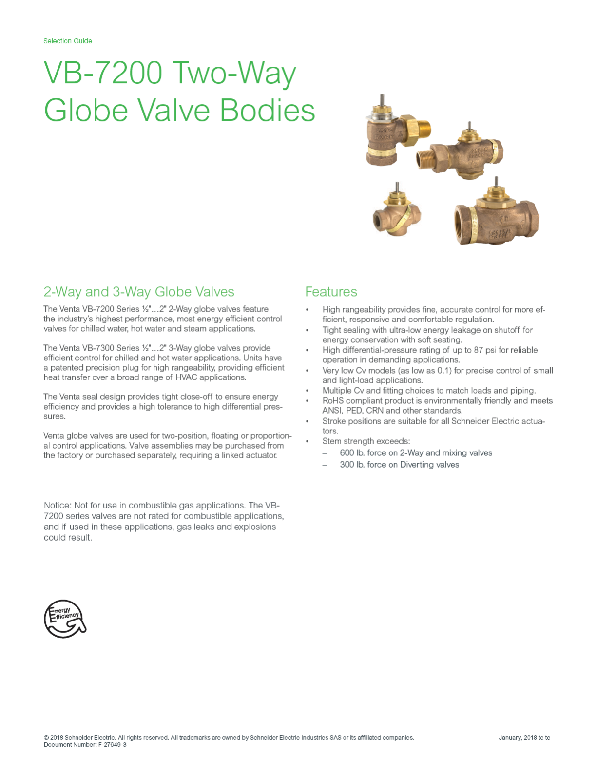
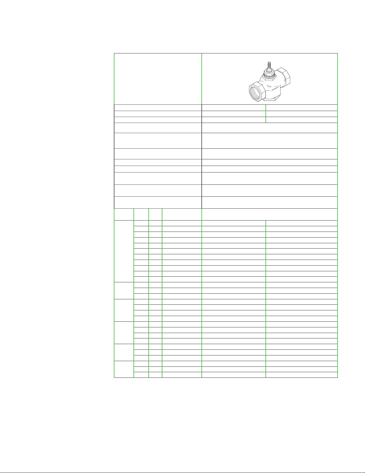
Product Selection: Brass Trim Threaded with Soft Seats
Selection Guide
Threaded NPT
Threaded NPT
2-Way Brass Trim Body Type
Series Part Number
Pipe Sizes
Stem Action
ANSI Pressure Class
ANSI Seat Leakage
b
Control Media and Temperature
Flow Curve
Allowable ΔP for Water
b
Max. inlet pressure, saturated steam
Max ΔP for sizing, saturated steam
Max ΔP at close-off, saturated steam
Designed to ANSI V with ANSI IV above 35 psi (241 kPa) close off. Long term seat leakage dependent on
20…281°F (-7 to 138°C) water (up to 60% glycol/water solution), low pressure, saturated, treated steam
b
b
80% of inlet pressure up to 15 psig and 42% of absolute (gage pressure plus 14.7) inlet pressure above 15
VB-7213-0-4- VB-7223-0-4-
½"…2"
Up Open Up Closed
250 psi (up to 400 psi below 150°F)
proper water conditioning maintenance of the system.
Modified Equal Percentage
87 psi (600 kPa) Max. for normal life
35 psi (240 kPa)
psig inlet
Inlet pressure (35 psi) (actuator must be rated to provide close-off pressure)
a
Size Cv Kvs Rangeability greater than Valve Body Par t Numbers
0.4 0.3 100:1 VB-7213-0-4-01 VB-7223-0-4-01
1.3 1.1 100:1 VB-7213-0-4-02 VB-7223-0-4-02
½”
2.2 1.9 100:1 VB-7213-0-4-03 VB-7223-0-4-03
4.4 3.8 100:1 VB-7213-0-4-04 VB-7223-0-4-04
5.5 4.8 100:1 VB-7213-0-4-05 VB-7223-0-4-05
¾”
7.5 6.5 100:1 VB-7213-0-4-06 VB-7223-0-4-06
10 8.7 100:1 VB-7213-0-4-07 VB-7223-0-4-07
1”
14 12.1 100:1 VB-7213-0-4-08 VB-7223-0-4-08
20 17.3 100:1 VB-7213-0-4-09 VB-7223-0-4-09
1¼”
28 24.2 100:1 VB-7213-0-4-10 VB-7223-0-4-10
1½”
40 34.6 100:1 VB-7213-0-4-11 VB-7223-0-4-11
2”
a To minimize noise, ensure the flow rate in the piping is less than 10 ft (3M) / Second and the differential pressure is less than 35 psi (241 kPa), operating
with differential pressures above 35 psi may result in additional noise but is acceptable up to 87 psi (600 kPa). Operating within the cavitation zone
may result in noise and internal valve damage.
b Maximum recommended differential pressure in open position. Do not exceed recommended differential pressure (pressure drop), as integrity of
parts may be affected.
c Refer to Seat Leakage Classes table.
Januar y, 2018 tc © 2018 Schneider Elect ric. All rights rese rved. A ll trademarks are ow ned by Schne ider Elect ric Indust ries SA S or its aff iliated co mpanies.
Document Number: F-27649- 3
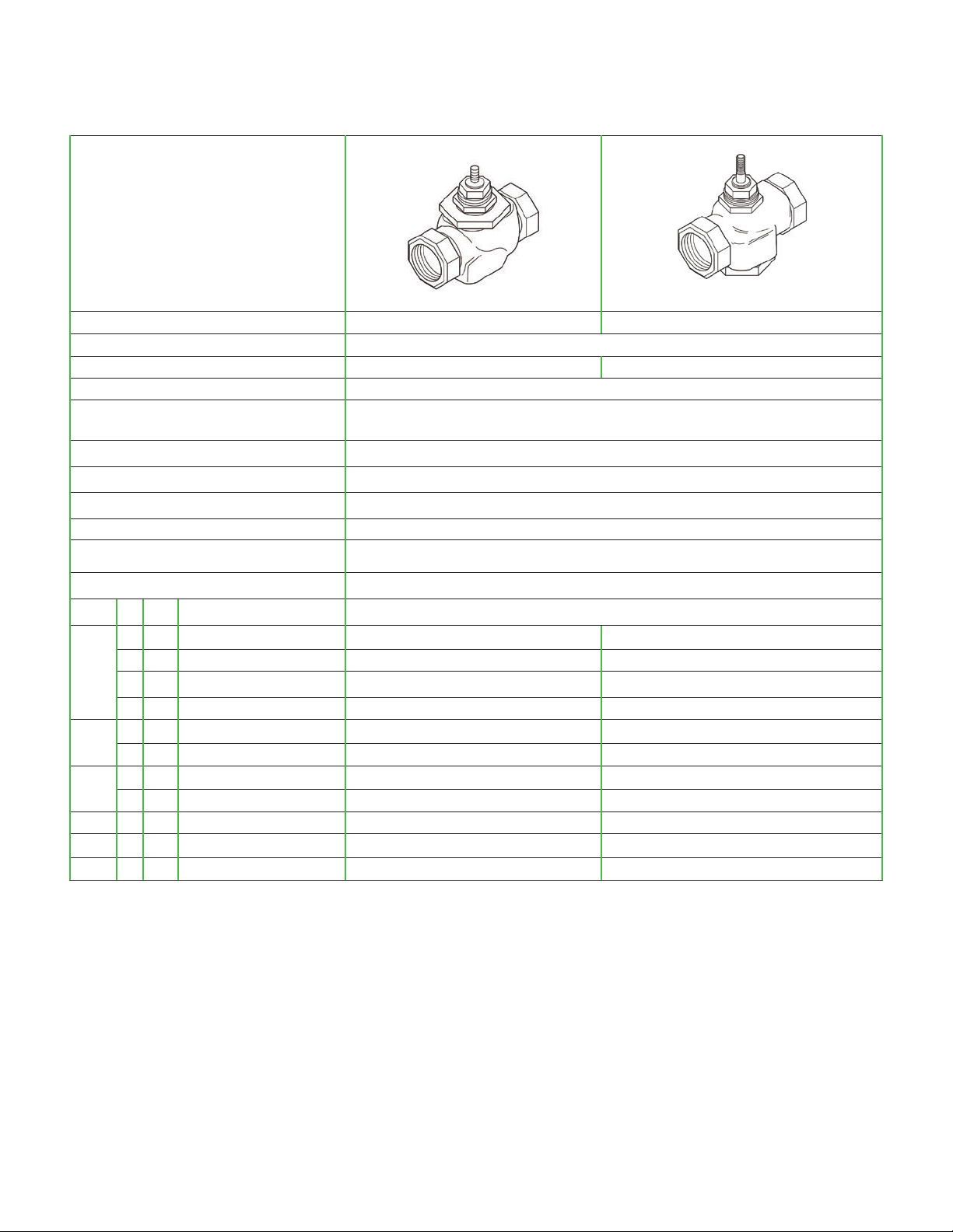
Selection Guide
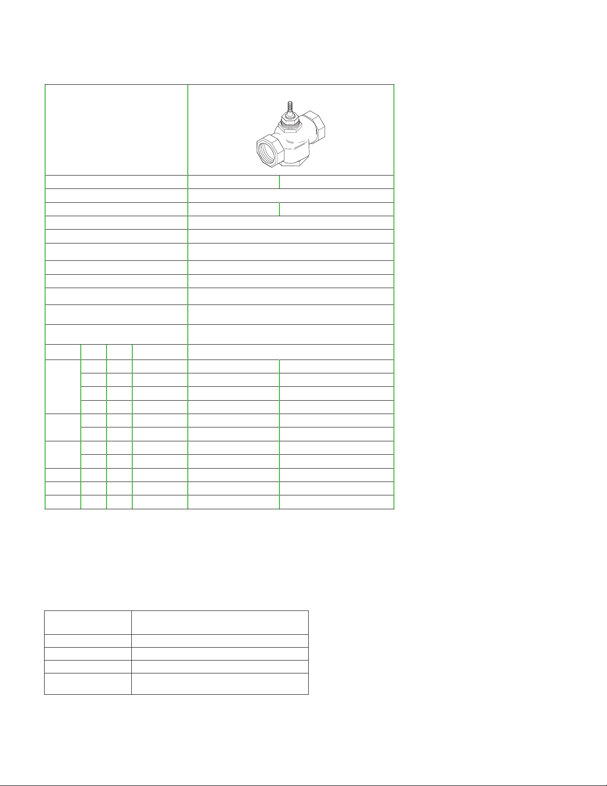
Product Selection: Brass Trim Copper Connection with Soft Seats
5/8” OD 45° SAE Flared Union Sweat
2-Way Brass Trim
Body Type
Series Part Number VB-7212-0-4- VB-7222-0-4- VB-7214-0-4- VB-7224-0-4Pipe Sizes
Stem Action
Up Open Up Closed Up Open Up Closed
ANSI Pressure Class
ANSI Seat Leakage
Control Media and
Temperature
e
20…281°F (-7 to 138°C) water (up to 60% glycol/water solution), low pressure, treated steam
Flow Curve
Allowable ΔP for Water
b
35 psi (241 kPa) Max. for normal lifea 87 psi (600 kPa) Max. for normal life
Max. inlet pressure, saturated
steam
Max ΔP for sizing, saturated steam
Max ΔP at close-off, saturated
b
steam
b
Size Cv Kvs Rangeabilityc Valve Body Par t Numbers
0.4 0.3 5:1 VB-7212-0-4-01 VB-7222-0-4-01 VB-7214-0-4-01
1.3 1.1 15:1 VB-7212-0-4-02 VB-7222-0-4-02 VB-7214-0-4-02
½”
2.2 1.9 25:1 VB-7212-0-4-03 VB-7222-0-4-03 VB-7214-0-4-03
4.4 3.8 40:1 VB-7212-0-4-04 VB-7222-0-4-04 VB-7214-0-4-04
5.5 4.8 50:1 – – VB-7214-0-4-05
¾”
7.5 6.5 60:1 – – VB-7214-0-4-06
10 8.7 60:1 – – VB-7214-0-4-07
1”
14 12.1 60:1 – – VB-7214-0-4-08
20 17.3 75:1 – – VB-7214-0-4-09
1¼”
28 24.2 75:1 – – VB-7214-0-4-10
1½”
40 34.6 75:1 – – VB-7214-0-4-11
2”
a,e To minimize noise, ensure the flow rate in the piping is less than 10 ft (3M) / Second and the differential pressure is less than 35 psi (241 kPa), operating with
differential pressures above 35 psi may result in additional noise but is acceptable up to 87 psi (600 kPa). Operating within the cavitation zone may result in noise
and internal valve damage.
b Maximum recommended differential pressure in open position. Do not exceed recommended differential pressure (pressure drop), as integrity of parts may be
affected. Exceeding maximum recommended differential pressure voids product warranty.
c The VB-7214-0-4- and VB-7224-0-4- ½"…2" series valves all have rangeabilities greater than 100:1.
d These part numbers do not have RoHs compliant nuts and tail pieces.
½” I.D. ½"…2"
250 psi (up to 400 psi below 150°F)
Designed to ANSI V with ANSI IV above 35 psi (241 kPa)
ANSI IV
close off with long term seat leakage dependent on proper
water conditioning
maintenance of the system.
Modified Equal Percentage
35 psi (240 kPa)
80% of inlet pressure up to 15 psig and 42% of absolute (gauge pressure plus 14.7)
inlet pressure above 15 psig inlet
Inlet pressure (actuator must be rated to provide close-off pressure)
c
c
c
c
c
c
cd
cd
cd
cd
cd
VB-7224-0-4-01
VB-7224-0-4-02
VB-7224-0-4-03
VB-7224-0-4-04
VB-7224-0-4-05
VB-7224-0-4-06
VB-7224-0-4-07
VB-7224-0-4-08
VB-7224-0-4-09
VB-7224-0-4-10
VB-7224-0-4-11
e
c
c
c
c
c
c
cd
cd
cd
cd
cd
Seat Leakage Classes
ANSI/FCI 70-2
Leakage Class
Class II 0.5% of rated Cv
Class III 0.1% of Rated Cv
Class IV 0.01% of Rated Cv
Class V 0.0005 ml per minute per inch of orifice diameter per psi differential
© 2018 Schneider Elect ric. All rights rese rved. A ll trademarks are ow ned by Schne ider Elect ric Indust ries SA S or its aff iliated co mpanies. Januar y, 2018 tc
Docume nt Number : F-27649 -3
Maximum Seat Leakage
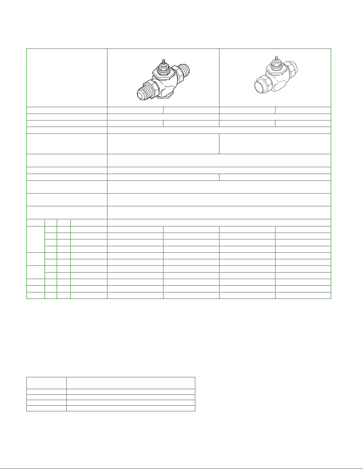
Selection Guide
Product Selection: Brass Trim Soft Seat Union for Radiators and Other Applications
Union Angle NPT Union Straight NPT Union Straight NPT
2-Way Brass Trim Body Type
Series Part Number
Pipe Sizes
Stem Action
ANSI Pressure Class
ANSI Seat Leakage
e
VB-7211-0-3- VB-7211-0-4- VB-7221-0-4-
½"…1¼”
Up Open Up Open Up Closed
250 psi (up to 400 psig below 150°F)
Designed to ANSI V with ANSI IV above 35 psi (241 kPa) close off with long term
Class IV
seat leakage dependent on proper water conditioning
maintenance of the system.
Control Media and
Temperature
Flow Curve
Allowable ΔP for Water
b
Max inlet pressure
for saturated steam
Max ΔP for sizing,
saturated steam
Max ΔP at close-off,
saturated steam
Size Cv Kvs
0.4 0.3 5:1 VB-7211-0-3-01 VB-7211-0-4-01
1.3 1.1 15:1 VB-7211-0-3-02 VB-7211-0-4-02
2.2 1.9 25:1 VB-7211-0-3-03 VB-7211-0-4-03
½”
4.4 3.8 40:1 – VB-7211-0-4-04
b
b
Rangeability
Greater Than
c
20…281°F (-7 to 138°C) water (up to 60% glycol/water solution), low pressure, treated steam
Modified Equal Percentage
35 psi (241 kPa)
Max. for normal lifea
87 psi (600 kPa) Max. for normal lifed
35 psi (240 kPa)
80% of inlet pressure up to 15 psig and 42% of absolute (gauge pressure plus 14.7)
inlet pressure above 15 psig inlet
Inlet pressure (35 psi) (actuator must be rated to provide close-off pressure)
Valve Body Par t Numbers
c
c
c
c
VB-7221-0-4-01
VB-7221-0-4-02
VB-7221-0-4-03
VB-7221-0-4-04
c
c
c
c
5.0 4.3 40:1 VB-7211-0-3-04 – –
5.5 4.8 50:1 VB-7211-0-3-05 VB-7211-0-4-05
7.5 6.5 60:1 – VB-7211-0-4-06
¾”
c
c
VB-7221-0-4-05
VB-7221-0-4-06
c
c
8.5 7.4 50:1 VB-7211-0-3-06 – –
10 8.7 60:1 – VB-7211-0-4-07
14 12.1 60:1 VB-7211-0-3-07 VB-7211-0-4-08
1”
c
c
VB-7221-0-4-07
VB-7221-0-4-08
c
c
16 13.8 75:1 VB-7211-0-3-08 – –
1¼”
20 17.3 75:1 – VB-7211-0-4-09
c
VB-7221-0-4-09
22 19 75:1 VB-7211-0-3-09 – –
c
a,d To minimize noise, ensure the flow rate in the piping is less than three meters (10ft)/second and the differential pressure is less than 35 psi (241 kPa). Operating
within the cavitation zone or an operating differential pressure above 35 psi (241 kPa) may result in noise and internal valve damage.
b Maximum recommended differential pressure in open position. Do not exceed recommended differential pressure (pressure drop), as integrity of
parts may be affected. Exceeding maximum recommended differential pressure voids product warranty.
c The VB-7211-0-4-xx and VB-7221-0-4-xx series valves all have rangeabilities greater than 100:1.
e Refer to Seat Leakage Classes table.
Januar y, 2018 tc © 2018 Schneider Elect ric. All rights rese rved. A ll trademarks are ow ned by Schne ider Elect ric Indust ries SA S or its aff iliated co mpanies.
Document Number: F-27649- 3
Selection Guide
Product Selection: Stainless Steel Trim Threaded with Soft Seats
Threaded NPT
2-Way Stainless Trim
(Soft Seal) Body Type
Series Part Number VB-7253-0-4- VB-7263-0-4Pipe Sizes
Stem Action
ANSI Pressure Class
Designed to ANSI V with ANSI IV above 35 psi (241 kPa) close off.
Seat Leakagec
Control Media and Temperature
Long term seat leakage dependent on proper water conditioning main-
20…340°F (-7 to 171°C) water (up to 60% glycol/water solution), low
Flow Curve
Allowable ΔP for Waterb
Max. inlet pressure,
saturated steam
Max ΔP for sizing,
80% of inlet pressure up to 15 psig and 42% of absolute (gauge pres-
saturated steamb
Max ΔP at close-off,
Inlet pressure (100 psi) (actuator must be rated to provide close-off
saturated steamb
Size Cv Kvs
0.1 0.09 13:1 - VB-7263-0-4-31
0.22 0.2 18:1 - VB-7263-0-4-33
0.4 0.3 100:1 VB-7253-0-4-01 VB-7263-0-4-01
0.75 0.6 100:1 - VB-7263-0-4-34
1.0 0.9 100:1 - VB-7263-0-4-36
1.3 1.1 100:1 VB-7253-0-4-02 VB-7263-0-4-02
½”
1.8 1.6 100:1 - VB-7263-0-4-28
2.2 1.9 100:1 VB-7253-0-4-03 VB-7263-0-4-03
2.9 2.5 100:1 - VB-7263-0-4-30
3.25 2.8 100:1 - VB-7263-0-4-39
4.4 3.8 100:1 VB-7253-0-4-04 VB-7263-0-4-04
5.5 4.8 100:1 VB-7253-0-4-05 VB-7263-0-4-05
6.3 5.4 100:1 - VB-7263-0-4-41
¾”
7.5 6.5 100:1 VB-7253-0-4-06 VB-7263-0-4-06
8.2 7.1 100:1 - VB-7263-0-4-51
9.0 7.8 100:1 - VB-7263-0-4-52
1”
10 8.7 100:1 VB-7253-0-4-07 VB-7263-0-4-07
12 10.4 100:1
14 12.1 100:1 - VB-7263-0-4-61
1¼”
1½”
a To minimize noise, ensure the flow rate in the piping is less than 10 ft (3M) / Second and the differential pressure is less than 35 psi (241 kPa), operating with
differential pressures above 35 psi may result in additional noise but is acceptable up to 87 psi (600 kPa). Operating within the cavitation zone may result in noise and
internal valve damage.
b Maximum recommended differential pressure in open position. Do not exceed recommended differential pressure (pressure drop), as integrity of parts may be
affected. Exceeding maximum recommended differential pressure voids product warranty.
c Refer to Seat Leakage Classes table.
16 13.8 100:1 - VB-7263-0-4-62
18 15.6 100:1 - VB-7263-0-4-63
20 17.3 100:1 VB-7253-0-4-09 VB-7263-0-4-09
22 19.0 100:1 - VB-7263-0-4-71
24 20.8 100:1 - VB-7263-0-4-72
28 24.2 100:1 VB-7253-0-4-10 VB-7263-0-4-10
31 26.8 100:1 - VB-7263-0-4-81
34 29.4 100:1 - VB-7263-0-4-82
2”
40 34.6 100:1 VB-7253-0-4-11 VB-7263-0-4-11
Rangeability
Greater Than
½"…2" ½"…2"
Up Open Up Closed
250 psi (up to 400 psi below 150°F)
tenance of the system.
pressure, treated steam
Modified Linear
87 psi (600 kPa) Max. for normal lifea
100 psi (690 kPa)
sure plus 14.7) inlet pressure above 15 psig inlet
pressure)
Valve Body Par t Numbers
VB-7253-0-4-08 VB-7263-0-4-08
© 2018 Schneider Elect ric. All rights rese rved. A ll trademarks are ow ned by Schne ider Elect ric Indust ries SA S or its aff iliated co mpanies. Januar y, 2018 tc
Docume nt Number : F-27649 -3
Product Selection: Stainless Steel Trim Threaded with Metal to Metal Seats
Threaded NPT
2-Way Stainless Trim (Metal to Metal)
Body Type
Series Part Number VB-7273-0-4- VB-7283-0-4-
Pipe Sizes
Stem Action
ANSI Pressure Class
Seat Leakage
c
Control Media and Temperature
Up Open Up Closed
250 psi (up to 400 psig below 150°F)
20…400°F (-7 to 204°C) water (up to 60% glycol/water solution),
low pressure, treated steam
Flow Curve
Allowable ΔP for Waterb
87 psi (600 kPa) Max. for normal life
Max Inlet Pressure, saturated steam
Max ΔP for sizing,
saturated steam
Max ΔP at close-off,
saturated steam
b
b
80% of inlet pressure up to 15 psig and 42% of absolute (gauge
pressure plus 14.7) inlet pressure above 15 psig inlet
Inlet pressure (150 psi) (actuator must be rated to provide close-
Size Cv Kvs Rangeability Valve Body Part Numbers
0.4 0.3 5:1 VB-7273-0-4-01 VB-7283-0-4-01
½”
¾”
1¼”
1½”
1.3 1.1 15:1 VB-7273-0-4-02 VB-7283-0-4-02
2.2 1.9 25:1 VB-7273-0-4-03 VB-7283-0-4-03
4.4 3.8 40:1 VB-7273-0-4-04 VB-7283-0-4-04
5.5 4.8 50:1 VB-7273-0-4-05 VB-7283-0-4-05
7.5 6.5 60:1 VB-7273-0-4-06 VB-7283-0-4-06
1”
2”
10 8.7 60:1 VB-7273-0-4-07 VB-7283-0-4-07
12 10.4 75:1 VB-7273-0-4-08 VB-7283-0-4-08
20 17.3 75:1 VB-7273-0-4-09 VB-7283-0-4-09
28 24.2 75:1 VB-7273-0-4-10 VB-7283-0-4-10
40 34.6 75:1 VB-7273-0-4-11 VB-7283-0-4-11
½"…2"
ANSI III
Modified Linear
a
150 psi (1034 kPa)
off pressure)
Selection Guide
a To minimize noise, ensure the flow rate in the piping is less than 10 ft (3M) / Second and the differential pressure is less than 35 psi (241 kPa), operating with
differential pressures above 35 psi may result in additional noise but is acceptable up to 87 psi (600 kPa). Operating within the cavitation zone may result in noise
and internal valve damage.
b Maximum recommended differential pressure in open position. Do not exceed recommended differential pressure (pressure drop), as integrity of parts may be
affected. Exceeding maximum recommended differential pressure voids product warranty.
c Refer to Seat Leakage Classes table below.
Seat Leakage Classes
ANSI/FCI 70-2
Leakage Class
Class II 0.5% of rated Cv
Class III 0.1% of Rated Cv
Class IV 0.01% of Rated Cv
Class V 0.0005 ml per minute per inch of orifice diameter per
Januar y, 2018 tc © 2018 Schneider Elect ric. All rights rese rved. A ll trademarks are ow ned by Schne ider Elect ric Indust ries SA S or its aff iliated co mpanies.
Document Number: F-27649- 3
Maximum Seat Leakage
psi differential

Selection Guide
Flow Characteristics
Two-way valves with brass plugs have modified equal percentage flow curves and valves with stainless steel plugs have
modified linear flow curves. With modified equal percentage flow curves, for equal increments of valve stem stroke,
the change in flow rate with respect to valve stroke may be
expressed as a constant percent of the flow rate at the time
of the change. The change of flow rate with respect to valve
stroke is relatively small when the valve plug is near the valve
seat and relatively high when the valve plug is nearly wide
open. With modified linear flow curves, the flow is directly proportional to the valve stem position.
100%
90%
80%
70%
60%
50%
Flow
40%
30%
20%
10%
0%
Closed OpenStroke
316 Stainless Trim
Modified Linear
0%
10%
20%
30%
Brass Trim
40%
50%
Modified
Equal
Percentage
60%
70%
80%
90%
100%
Temperature Pressure Ratings
Consult the appropriate valve linkage general instruction
sheet for the effect of valve body ambient temperatures on
specific actuators. Ratings conform with published values and
disclaimer.
VB-72xx-0-4-P (Cast Bronze Body)
Standards: Pressure to ANSI B16.15 Class 250 with 400 psig
up to 150° F decreasing to 321 psig at 281° F, ASTM B584
321
(2218)
Limits for
VB-727X, -728X
Limits for
VB-725X, -726X
Limits for
VB-721X, -722X
400 (204)
340 (171)
281 (138)
200 (93)
150 (65)
Temperature – F (C)
100 (38)
50 (10)
0 50 100 150 200 250 300 350 400 psig
(345) (380) (1084) (1379) (1724) (2068) (2458) (2758) kPa
Pressure – psig (kPa)
1 kPa = .01 bar
270
(1865)
286
(1973)
Caution: Do not use valves beyond rating of piping system and
components.Consult ANSI B16.22 for ratings of solder joint
pressure fittings.
VB-7200 Two-Way Globe Valves Material Specifications
VB-7200 Valve
Series
Body
Seat
Stem
Plug
Packing
1/2” and 3/4” PTFE
Seal
1” to 2” EPDM
Packing and Seal materials: Polytetrafluoroethylene (PTFE), ethylene propylene diene monomer (EPDM)
VB-7211-0-4
(1/2” to 1-1/4”),
VB-7213, VB-7221-0-4
(1/2” to 1-1/4”),
VB-7211-0-3
(1/2” to 1-1/4”),
VB-7212 (1/2”),
VB-7222 (1/2”)
VB-7251-0-3
(1/2” to 1-1/4”),
VB-7251-0-4
(1/2” to 1-1/4”)
VB-7253, VB-7255,
VB-7263, VB-7265
VB-7223, VB-7214,
VB-7224, VB-7215,
VB-7225
Bronze, ASTM B584
Bronze, ASTM B584 316 Stainless Steel
316 Stainless Steel
Brass 316 Stainless Steel
Spring-Loaded PTFE/EPDM
EPDM PTFE
VB-7273, VB7275, VB-7283,
VB-7285
Metal to Metal 316
Stainless Steel
© 2018 Schneider Elect ric. All rights rese rved. A ll trademarks are ow ned by Schne ider Elect ric Indust ries SA S or its aff iliated co mpanies. Januar y, 2018 tc
Docume nt Number : F-27649 -3


Selection Guide
Cavitation Limitations on Valve Pressure Drop
A valve selected with too high a pressure drop can cause erosion of seals and/or wire drawing of the seat. In addition, cavitation can
cause noise, damage to the valve trim (and possibly the body), and choke the flow.
Do not exceed the maximum differential pressure (pressure drop) for the valve selected.
The following formula can be used on higher temperature water systems, where cavitation could be a problem, to estimate the
maximum allowable pressure drop across the valve:
Pm = 0.5 (P1 – Pv)
Where:
Pm = Maximum allowable pressure drop (psi)
P1 = Absolute inlet pressure (psia)
Pv = Absolute vapor pressure (psia)
Note: Add 14.7 psi to gauge supply pressure to obtain absolute pressure value. For example, if a valve is controlling 200°F water
at an inlet pressure of 18 psig, the maximum pressure drop allowable would be:
Pm = 0.5 [(18 + 14.7) – 11.53] = 10.6 psi
(Vapor pressure of 200°F water is 11.53 psia)
If the pressure drop for this valve is less than 10.6 psi, cavitation should not be a problem. Systems where cavitation is shown
to be a problem can sometimes be adjusted to provide higher downstream back pressures. Valves having harder seat materials
should be furnished if inlet velocities cannot be lowered.
Vapor Pressure Of Water Table
Temp
(°F)
40 0.12 90 0.70 140 2.89 190 9.34
50 0.18 100 0.95 150 3.72 200 11.53
60 0.26 110 1.28 160 4.74 210 14.12
70 0.36 120 1.69 170 5.99 220 17.19
80 0.51 130 2.22 180 7.51 230 20.78
Pressure
(psia)
Temp.
(°F)
Pressure
(psia)
Temp.
(°F)
Pressure
(psia)
Temp.
(°F)
Pressure
(psia)
Seat Leakage Classes
ANSI/FCI 70-2
Leakage Class
Class II 0.5% of rated Cv
Class III 0.1% of Rated Cv
Class IV 0.01% of Rated Cv
Class V 0.0005 ml per minute per inch of orifice diameter per psi differential
Maximum Seat Leakage
Water Capacity Graph Instructions
To Select the approproate valve Cv from the Graph:
1. Select the required flow from the “Flow in GPM” axis.
2. Select available pressure drop from the “Pressure Drop in psi” axis.
3. Select the appropriate line and follow to the Capacity Cv (Kv) listing to choose the closest valve Cv flow coefficient.
4. Confirm the selection by calculation from the water equations (optional).
© 2018 Schneider Elect ric. All rights rese rved. A ll trademarks are ow ned by Schne ider Elect ric Indust ries SA S or its aff iliated co mpanies. Januar y, 2018 tc
Docume nt Number : F-27649 -3

Water Capacity for 0.1 to 9.0 Cv Valves
Selection Guide
9 (7.8)
8.5 (7.4)
8.2 (7.1)
7.5 (6.5)
6.3 (5.4)
5.5 (4.8)
5 (4.3)
4.4 (3.8)
3.25 (2.8)
2.9 (2.5)
2.2 (1.9)
1.8 (1.6)
1.3 (1.1)
1 (.9)
.75 (.6)
.4 (.3)
100.0
50.0
10.0
5.0
.22 (.2)
.1 (0.9)
* Consult pages 2 - 6 for the Allowable ∆P for
Capacity Cv (Kv)
Water rating to verify what valve series can be
operated above a 35 psi pressure drop
35*5087 10 5 1
1 GPM = .06309 l/s = .22712 cubic m/h
Flow in GPM
1.0
0.5
0.1
Pressure Drop in psi
Januar y, 2018 tc © 2018 Schneider Elect ric. All rights rese rved. A ll trademarks are ow ned by Schne ider Elect ric Indust ries SA S or its aff iliated co mpanies.
Document Number: F-27649- 3

Selection Guide
Water Capacity for 10 to 40 Cv Valves
40 (34.6)
34 (29.4)
31 (26.8)
28 (24.2)
24 (20.8)
22 (19)
20 (17.3)
18 (15.6)
16 (13.8)
14 (12.1)
12 (10.4)
10 (8.7)
500
Flow in GPM
100
Capacity Cv (Kv)
* Consult pages 2 - 6 for the Allowable ∆P for
Water rating to verify what valve series can be
operated above a 35 psi pressure drop
1 GPM = .06309 l/s = .22712 cubic m/h
50
10
110 535*5087
Pressure Drop in psi
© 2018 Schneider Elect ric. All rights rese rved. A ll trademarks are ow ned by Schne ider Elect ric Indust ries SA S or its aff iliated co mpanies. Januar y, 2018 tc
Docume nt Number : F-27649 -3


Selection Guide
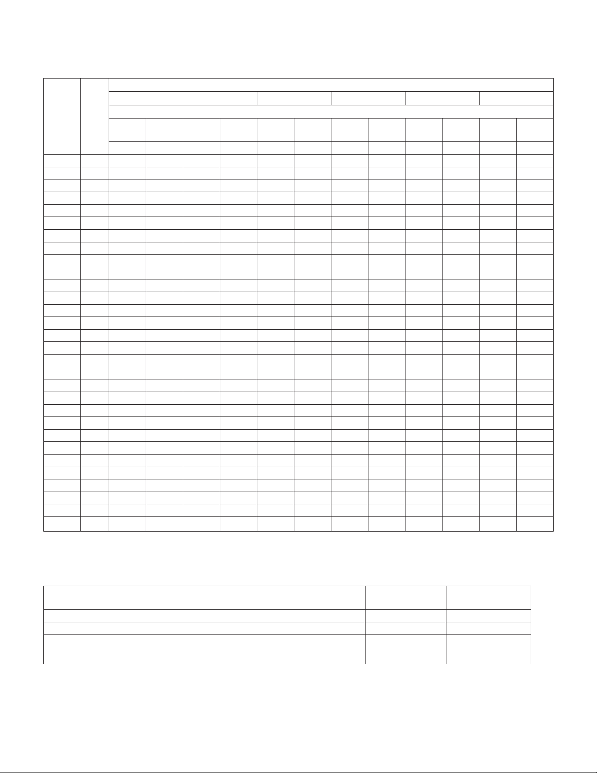
Steam Capacity in Pounds per Hour
Inlet Pressure (psig)
2 psig Inlet 5 psig Inlet 10 psig Inlet 15 psig Inlet 20 psig Inlet 25 psig Inlet
Cv Kv
0.1 0.09
0.22 0.2
0.4 0.3
0.75 0.6
1 0.9
1.3 1.1
1.8 1.6
2.2 1.9
2.9 2.5
3.25 2.8
4.4 3.8
5 4.3
5.5 4.8
6.3 5.4
7.5 6.5
8.2 7.1
8.5 7.4
9 7.8
10 8.7
12 10.4
14 12.1
16 13.8
18 15.6
20 17.3
22 19
24 20.8
28 24.2
31 26.8
34 29.4
40 34.6
a. Values are for saturated steam (K = 1). Left column under each inlet pressure is for two position control, and right column is for proportional control.
Differential Pressure (psi)
Two
Position
0.2 1.6 0.5 4 1 8 1.5 12 2 14 2.5 16
0.5 1.5 0.9 2.4 1.5 3.5 2.0 4.4 2.4 5.1 2.9 5.8
1.2 3.2 2.0 5.2 3.2 7.6 4.3 10 5.3 11 6.4 13
2.2 5.9 3.7 9.5 5.8 14 7.8 17 9.7 20 12 23
4.1 11 7.0 18 11 26 15 33 18 38 22 44
5.4 15 9.3 24 15 35 20 44 24 51 29 58
7.1 19 12 31 19 45 25 57 32 66 38 76
10 27 17 43 26 62 35 79 44 92 52 105
12 32 20 52 32 76 43 96 53 112 64 129
16 43 27 69 42 101 57 127 70 148 84 169
18 48 30 77 47 113 63 142 79 166 94 190
24 65 41 105 64 153 86 192 107 225 127 257
27 74 46 119 73 173 98 219 121 255 145 292
30 81 51 131 80 191 107 240 133 281 159 321
34 93 59 150 92 218 123 275 153 322 182 368
41 111 70 178 110 260 146 328 182 383 217 438
45 121 76 195 120 284 160 359 199 419 237 479
46 125 79 202 124 295 166 372 206 434 246 497
49 133 84 214 131 312 176 393 218 460 260 526
54 147 93 238 146 347 195 437 243 511 289 584
65 177 112 285 175 416 234 525 291 613 347 701
76 206 130 333 204 485 273 612 340 715 405 818
87 236 149 380 234 555 312 700 388 817 463 935
98 265 167 428 263 624 351 787 437 919 521 1052
109 295 186 475 292 694 390 874 485 1021 579 1168
120 324 204 523 321 763 429 962 534 1124 636 1285
131 354 223 571 351 832 468 1049 582 1226 694 1402
153 413 260 666 409 971 546 1224 679 1430 810 1636
169 457 288 737 453 1075 605 1355 752 1583 897 1811
185 501 316 808 497 1179 663 1487 825 1736 984 1986
218 590 372 951 584 1387 780 1749 970 2043 1157 2337
Prop.
a
a
Two
Position
Prop.
Two
Position
Prop.
Two
Position
Prop.
Two
Position
Prop.
Two
Position
Prop.
Always select the correct valve series for the inlet steam pressure as shown below:
Valve Series Max Inlet Pressure for
Saturated Steam
VB-7273-0-4-, VB-7283-0-4-, VB-7275-0-4-, VB-7285-0-4- 150 psi (1034 kPa) 20 to 400°F (-7 to 204°C)
VB-7253-0-4-, VB-7263-0-4-, VB-7255-0-4-, VB-7265-0-4- 100 psi (690 kPa) 20 to 340°F (-7 to 171°C)
VB-7213-0-4-, VB-7223-0-4-, VB-7215-0-4-, VB-7225-0-4-, VB-7212-0-4-, VB-7222-0-4-,
VB-7214-0-4-, VB-7224-0-4-, VB-7211-0-3-, VB-7211-0-4-, VB-7221-0-4-, VB-7251-0-3-,
VB-7211-0-4-
35 psi (240 kPa) 20 to 281°F (-7 to 138°C)
1 Pound per Hour = 0.45359 Kilogram Per Hour
© 2018 Schneider Elect ric. All rights rese rved. A ll trademarks are ow ned by Schne ider Elect ric Indust ries SA S or its aff iliated co mpanies. Januar y, 2018 tc
Docume nt Number : F-27649 -3
Maximum Media Temperature
Steam Capacity in Pounds per Hour (continued)
Cv Kv Inlet Pressure (psig)
30 psig Inlet 35 psig Inlet 40 psig Inlet 50 psig Inlet 75 psig Inlet 100 psig Inlet
Differential Pressure (psi)
Two
Position
3 18 3.5 20 4 22 5 27 7.5 37 10 48
0.1 0.09
0.22 0.2
0.4 0.3
0.75 0.6
1 0.9
1.3 1.1
1.8 1.6
2.2 1.9
2.9 2.5
3.25 2.8
4.4 3.8
5 4.3
5.5 4.8
6.3 5.4
7.5 6.5
8.2 7.1
8.5 7.4
9 7.8
10 8.7
12 10.4
14 12.1
16 13.8
18 15.6
20 17.3
22 19
24 20.8
28 24.2
31 26.8
34 29.4
40 34.6
a. Values are for saturated steam (K = 1). Left column under each inlet pressure is for two position control, and right column is for proportional control.
3.4 6.6 3.8 7.3 4.3 8.0 5.2 9.6 7.4 13 9.7 17
7.4 14 8.4 16 9.4 18 11 21 16 29 21 37
13 26 15 29 17 32 21 38 30 53 39 68
25 49 29 55 32 60 39 72 56 99 73 127
34 66 38 73 43 80 52 96 74 132 97 170
44 85 50 95 56 105 67 124 97 172 126 221
60 118 69 132 77 145 93 172 134 238 175 306
74 145 84 161 94 177 114 211 164 291 214 373
97 191 111 212 124 233 150 278 216 384 282 492
109 214 124 238 139 262 168 311 242 431 315 552
148 289 168 322 188 354 228 421 328 583 427 747
168 329 191 366 214 402 259 479 372 662 485 849
185 362 210 402 235 443 285 526 410 729 534 934
211 414 240 461 269 507 327 603 469 835 612 1069
252 493 286 548 320 603 389 718 559 994 728 1273
275 539 313 600 350 660 425 785 611 1086 796 1392
285 559 324 621 363 684 441 814 633 1126 825 1443
302 592 343 658 385 724 466 861 670 1192 874 1528
336 658 381 731 427 805 518 957 745 1325 971 1697
403 789 458 877 513 966 622 1149 894 1590 1165 2037
470 921 534 1024 598 1127 726 1340 1043 1855 1359 2376
537 1052 610 1170 684 1287 829 1531 1192 2120 1553 2716
604 1184 687 1316 769 1448 933 1723 1341 2385 1747 3055
671 1315 763 1462 854 1609 1037 1914 1490 2649 1941 3395
738 1447 839 1609 940 1770 1140 2106 1639 2914 2136 3734
805 1578 916 1755 1025 1931 1244 2297 1788 3179 2330 4074
940 1841 1068 2047 1196 2253 1451 2680 2086 3709 2718 4753
1040 2039 1183 2267 1324 2494 1607 2967 2309 4107 3009 5262
1141 2236 1297 2486 1453 2736 1762 3254 2533 4504 3300 5771
1342 2631 1526 2925 1709 3219 2073 3829 2980 5299 3883 6790
Prop.
a
a
Two
Position
Prop.
Two
Position
Prop.
Two
Position
Prop.
Two
Position
Prop.
Two
Position
Selection Guide
Prop.
Always select the correct valve series for the inlet steam pressure as shown below:
Valve Series Max Inlet Pressure
for Saturated Steam
VB-7273-0-4-, VB-7283-0-4-, VB-7275-0-4-, VB-7285-0-4- 150 psi (1034 kPa) 20 to 400°F (-7 to 204°C)
VB-7253-0-4-, VB-7263-0-4-, VB-7255-0-4-, VB-7265-0-4- 100 psi (690 kPa) 20 to 340°F (-7 to 171°C)
VB-7213-0-4-, VB-7223-0-4-, VB-7215-0-4-, VB-7225-0-4-, VB-7212-0-4-, VB-7222-0-4-,
VB-7214-0-4-, VB-7224-0-4-, VB-7211-0-3-, VB-7211-0-4-, VB-7221-0-4-, VB-7251-0-3-,
VB-7211-0-4-
1 Pound per Hour = 0.45359 Kilogram Per Hour
Januar y, 2018 tc © 2018 Schneider Elect ric. All rights rese rved. A ll trademarks are ow ned by Schne ider Elect ric Indust ries SA S or its aff iliated co mpanies.
Document Number: F-27649- 3
35 psi (240 kPa) 20 to 281°F (-7 to 138°C)
Maximum Media
Temperature


Dimensions for Stem Up Open Valves
Threaded NPT and Rp: VB-7213-0-4-P, VB-7215-0-4-P
Selection Guide
Valve Por t Code
(P)
01, 02, 03, 04
05, 06
07, 08
09
10
11
Valve
Size
1/2” 3-1/16 (78)
3/4” 3-5/8 (92)
1”
1-1/4” 1-3/8 (35)
1-1/2” 5-3/8 (137) 1-1/2 (38) 2-7/16 (57)
2” 6-1/8 (156) 1-5/8 (41) 2-3/4 (70)
Dimensions in Inches (mm)
A B C D*
4-5/8 (118) 2-3/8 (60)
* Stem down
Union Sweat: VB-7214-4-P
Valve Por t Code
(P)
01, 02, 03, 04
05, 06
07, 08
09
10
11
Valve
Size
1/2”
3/4”
1” 6-5/8 (168) 1-3/4 (45)
1-1/4”
1-1/2”
2”
Dimensions in Inches (mm)
A B C D*
4-3/16
(106)
5-7/16
(138)
6-13/16
(173)
8-5/16
(211)
9-3/16
(233)
1-1/4 (32)
1-1/4 (32)
1-3/8
(35)
1-1/2
(38)
1-5/8
(41)
1-11/16 (43)
1-11/16
(43)
2
(51)
2-1/8 (54)
2-3/16 (56)
3/4
(19)
3/4
(19)
E
Stroke
7-16
(11)
E
Stroke
7-16
(11)
E
D
C
B
A
E
D
C
B
A
* Stem down
Januar y, 2018 tc © 2018 Schneider Elect ric. All rights rese rved. A ll trademarks are ow ned by Schne ider Elect ric Indust ries SA S or its aff iliated co mpanies.
Document Number: F-27649- 3


 Loading...