

Page 1
Smart Sensor
Contents
Installation 2
Operation 6
Configuration & Programming 6
Reading the Keypad 8
Display Programming 9
Displaying a Numeric Value 11
Manually Displaying Message Icons
on the LCD Module 13
Troubleshooting 14
Program Examples 14
1
Installation & User’s Guide
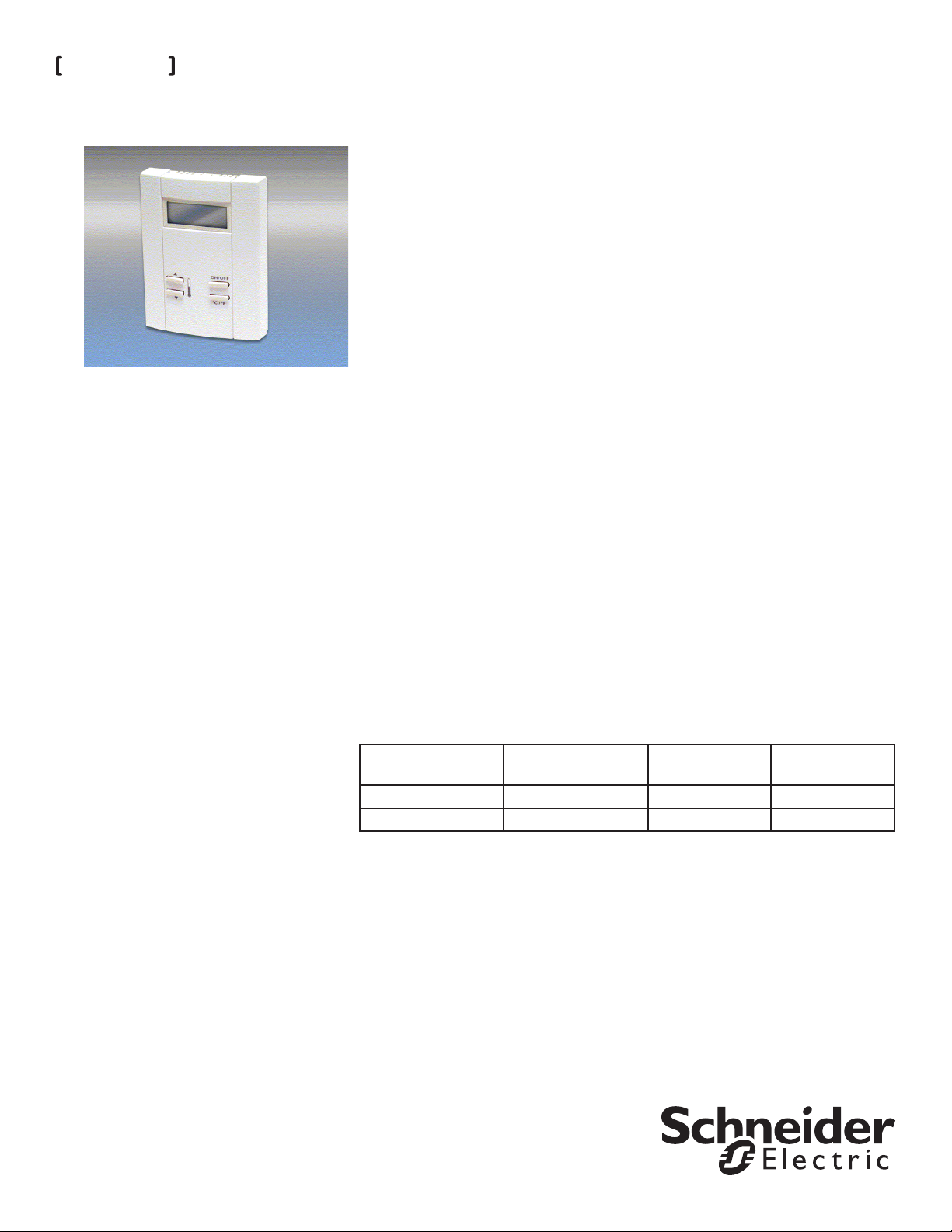
The Smart Sensor family of wall-mounted modules makes your building’s automation
system accessible to any tenant or operator in the facility, allowing them to quickly access
HVAC information and adjust personal comfort levels with little or no training.
Although it looks like a typical temperature sensor temperature sensor or thermostat,
the Smart Sensor, in addition, includes a display and a 6-button ergonomically designed
programmable keypad. With one touch of a finger, a user can scroll through building
parameters such as temperatures or pressures, view equipment status, change setpoints
and schedules, turn equipment on and off, or air balance VAV boxes.
The keys can be custom programmed to perform a wide variety of functions, including
switching a specific zone to occupied mode, signaling an alarm condition, adjusting the
amount of override time, arming or disarming a security system, and enforcing password
security. Programming the display and function keys is done with Andover’s Plain English
programming language.
The Smart Sensor module offers several built-in options to meet your particular building
needs, including the choice of either a 4-character LCD or 2-character LED display.
The Smart Sensor interfaces directly to Andover’s TCX 866 and TCX 867 controllers. The
Smart sensor can interface with Infinity controllers that contain EMX ports (e.g., TCX850, LCX-810, SCX-920) by using the TTS-SD-INFBUF interface board.
SMART SENSOR FAMILY CHARACTERISTICS
The following table lists the features included in the Smart Sensor family members:
Appendix A 15
LCD Operation & Control 15
LED Operation & Control 17
LED & LCD Keypad Operation 19
Model Temperature Sensor 4-Char LCD
Display
TTS-SD-LCD * *
TTS-SD-LED * *
After unpacking the unit, take care to not damage the packaging material, you must
reuse it if you ship the product back for repair.
PARTS INCLUDED WITH THE SMART SENSOR MODULE
Smart Sensor Module•
Hardware Reference Manual (this document)•
2-Char LED
Display
Page 2
Smart Sensor
Installation
MECHANICAL INSTALLATION
The sensor may be mounted directly on dry wall, or on any electrical outlet box with no
adapters required. This sensor is for indoor use only and is not suitable for use where
condensation may occur.
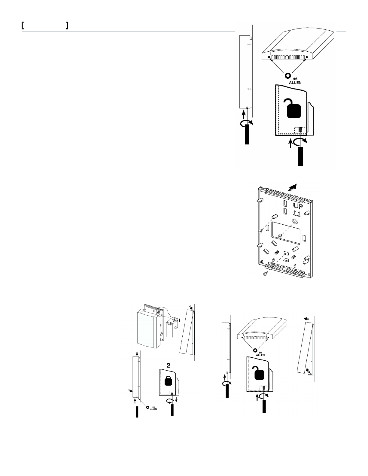
THE SENSOR COVER
The cover is fastened to the base using Allen screws.
The cover is removed by inserting a #6 Allen tool into the two Allen fasteners found in
the bottom of the case as shown, Figure 1.
Turn the screw clockwise (inward) until the case lifts easily.
Remove the cover by lifting the front bottom outward.
TO INSTALL THE BASE
Note: If you are mounting the sensor to an existing electrical box, skip steps 1, 2 and 3.
To prevent drafts from affecting the sensor reading, cover the openings in the back of
the case.
1. Place the case back on the surface of the wall area where the sensor is to be mounted
and mark the location of at least three mounting holes.
2. Drill the marked holes and insert wall anchors into the surface.
3. Mount the back using at least three screws as shown in
Figure 2.
4. Guide your facility wiring into the area of the case. Connect your wires to the probe
wires that are part of the cover assembly using wire nuts, (see electrical connection
section).
5. Collect any slack wire, fold and tuck into the case.
6. Fasten the cover to the mounted section. Hook the cover to the base as shown in
Figure 3.
7. Turn the Allen screws counterclockwise (outward) until the cover is locked in place.
2
FIGURE 1
AFTER MOUNTING: TO REMOVE THE COVER
Remove the cover from the case by inserting the tip of a small flat-head screwdriver
into the two tab release areas in the bottom of the case as shown. Remove the cover by
lifting the front bottom outward.
FIGURE 3
Schneider Electric
F- 2757 7-1 June 2010 dl
FIGURE 2
FIGURE 4
© 2010 Schneider Electric. All rights reserved.
Page 3
Smart Sensor
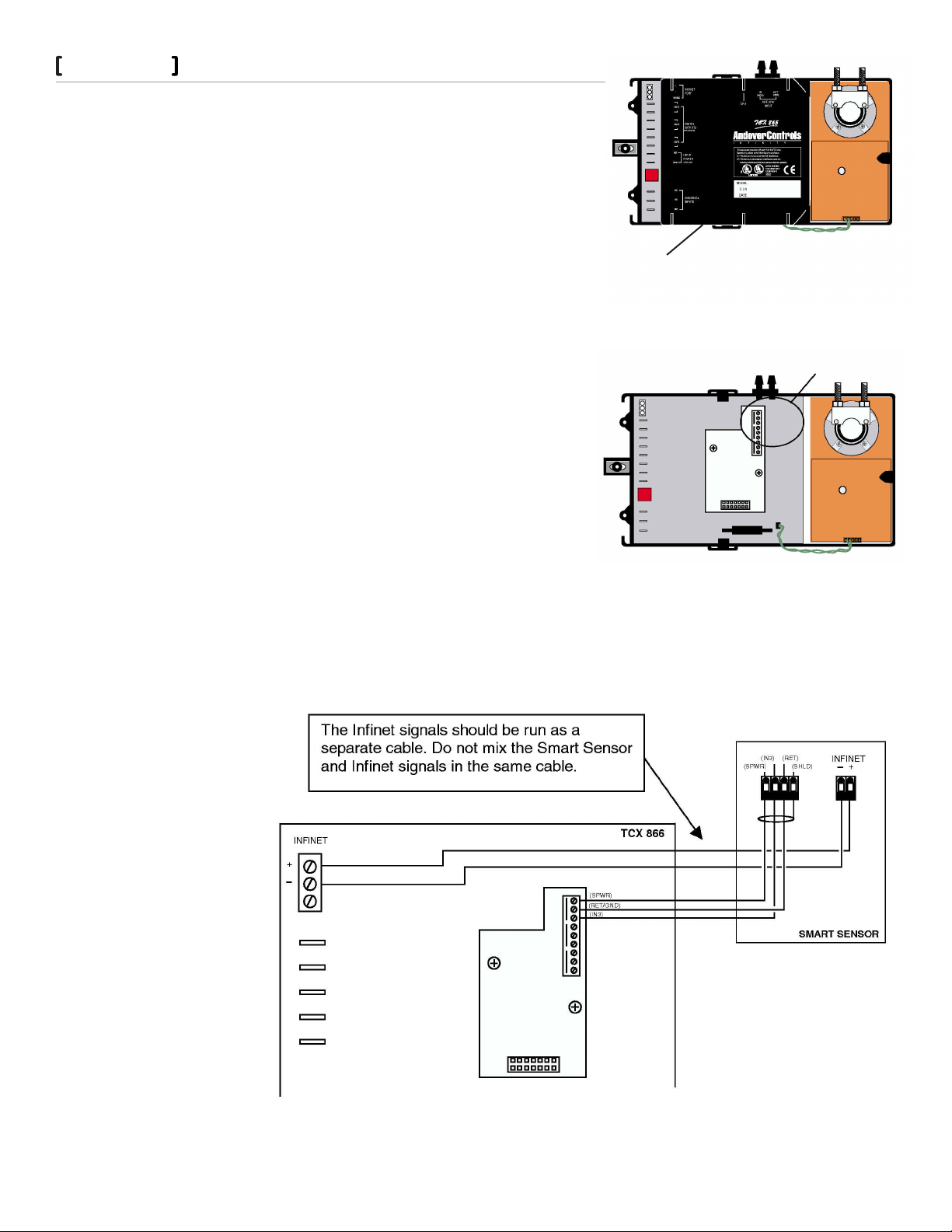
ELECTRICAL CONNECTION TO TCX 866
The Smart Sensor module is powered by and accessed through an
external TCX 866 VAV controller. The connection between the two
uses three wires. These wires attach to an internal terminal block
(Figure 7) located under the plastic cover of the TCX 866, Figure 6.
To access the terminal block and remove the cover, simply pull
outward on the two opposite tabs that lock the cover to the base
and pull upward.
CONNECT THE SMART SENSOR TO THE TCX 866 AS SHOWN IN
FIGURE 7.
The TCX 866 supplies power and communicates with the keypad
and the display of the Smart Sensor over a single wire (the SPWR
connection).
The RET line is the return for both the power supplied to the module
and the internal thermistor.
The IN3 signal is the active lead from the thermistor. It connects to
the IN3 Analog input to the TCX 866. Temperature readings from
the Smart Sensor are read as Input 3.
The (Infinet -) and (Infinet +) wires provide access to the Infinet for
the Lap-Top Service Tool connector on the bottom of the module.
3
Connection to the Smart Sensor is located
behind this plastic cover.
FIGURE 5
Connection to the Smart
Sensor is made here.
FIGURE 6
FIGURE 7
Schneider Electric
F- 2757 7-1 June 2010 dl
© 2010 Schneider Electric. All rights reserved.
Page 4
Smart Sensor
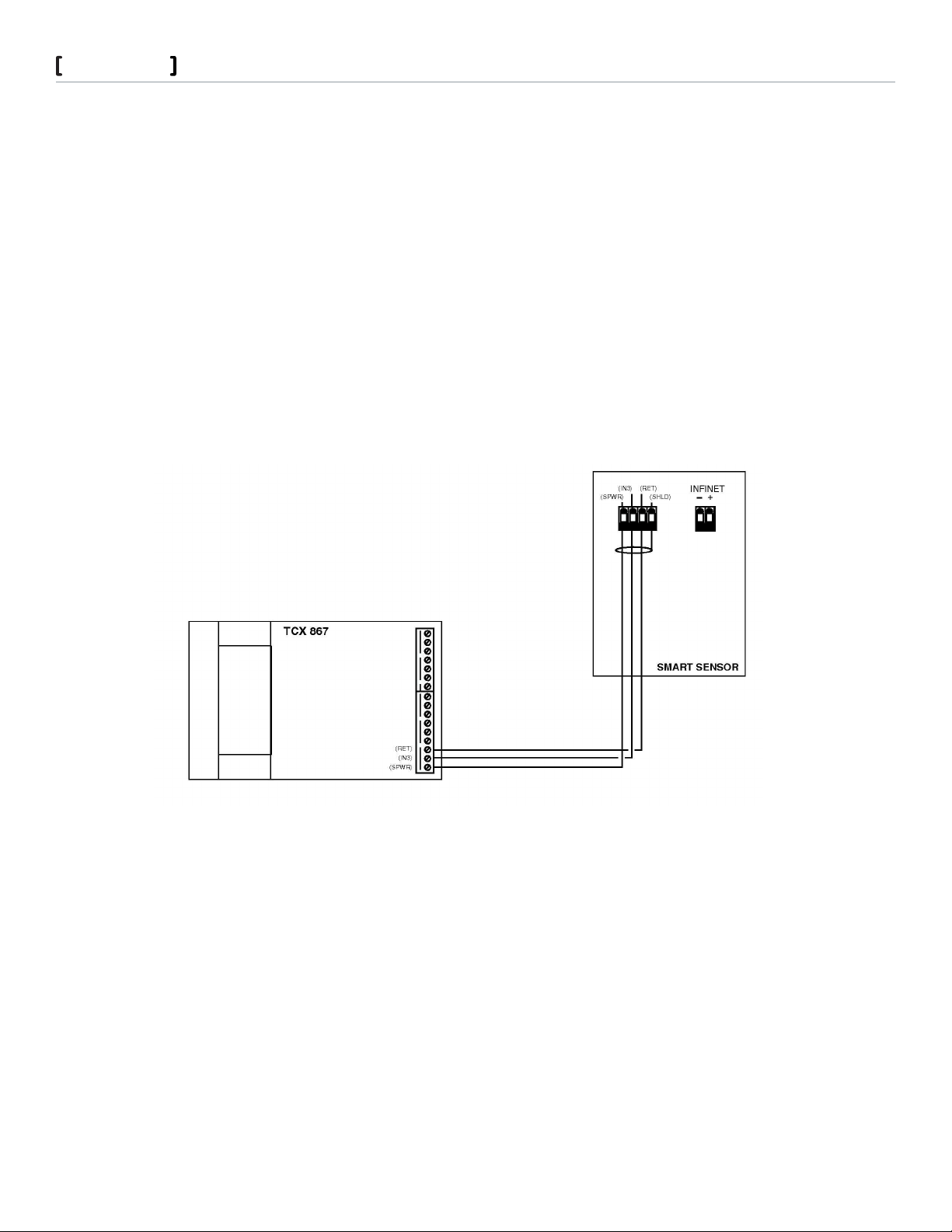
ELECTRICAL CONNECTION TO TCX 867
The interface between the TCX 867 and the Smart Sensor Bus consists of three wires connected to the following positions on
the sixteen-terminal output connector located on the right side of the Controller module:
14 RET
15 IN3
16 SPWR
The TEC 867 supplies power and communicates with the keypad and the display of the Smart Sensor device over a single wire
(the SPWR connection).
The RET line is the return for both the power supplied to the module and the internal thermistor.
The IN3 signal is the active lead from the Smart Sensor thermistor. It connects to the IN3 input to the TCX 867. Temperature
readings from the Smart Sensor are read as Input 3.
Figure 8 illustrates the connection between the two units.
Note: Input 3 is located on both the Input connector and on the 16-position Output connector. DO NOT USE the IN3
connection on the Input connector as a general temperature input when connecting the Smart Sensor.
4
FIGURE 8
Schneider Electric
F- 2757 7-1 June 2010 dl
© 2010 Schneider Electric. All rights reserved.
Page 5
Smart Sensor
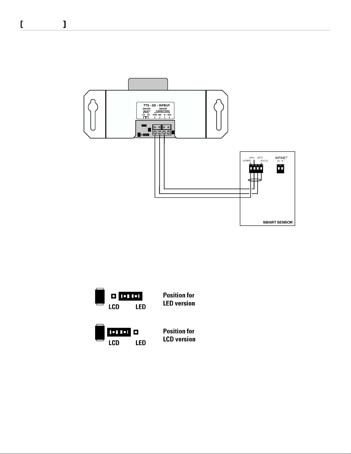
ELECTRICAL CONNECTION TO TTS-SD-INFBUF BOARD
1. Locate the interface wires from the Smart Sensor and route them to the Buffer Board.
2. Connect the wires as shown:
5
FIGURE 9
Position the Smart Sensor type jumper according to the version of sensor connected, Figure 10.
FIGURE 10
Schneider Electric
F- 2757 7-1 June 2010 dl
© 2010 Schneider Electric. All rights reserved.
Page 6
Smart Sensor
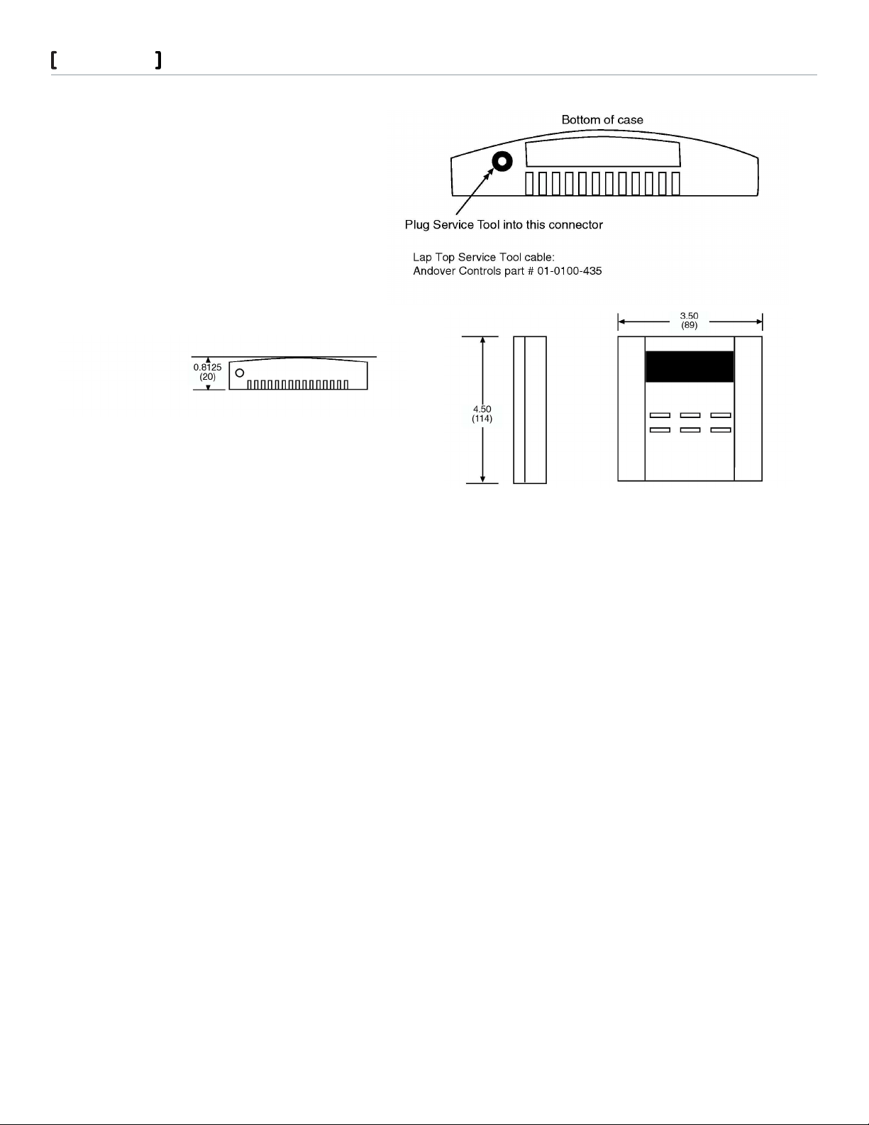
LAP TOP SERVICE TOOL/BALANCE TOOL CONNECTION
The Smart Sensor module includes an interface to the
Andover Controls Lap-Top Service Tool and the Balance Tool.
Tool connection to the Smart Sensor requires a special
adapter cable. This two wire shielded cable includes a special
connector.
6
To connect the module to the Tool, follow Figure 11.
FIGURE 11
Dimensions
The Smart Sensor modules are designed to be mounted flush with a
wall. The overall dimensions of the unit are as shown in Figure 12.
FIGURE 12
Operation
The Smart Sensor module requires connection to an external controller. After installation, the following tasks must be performed
before you can use the Smart Sensor:
1. Create a set of appropriately named points for the Smart Sensor using the information in the Configuration Table provided in this
section.
2. Connect the Smart Sensor module to the TCX 866, TCX 867 or to another Infinity controller using the TTS-SD-INFBUF interface.
3. Load and/or create Plain English programs in the controller to control and monitor the module. Information on reading from and
writing to the Smart Sensor is included in the Programming section of this manual.
TCX 866/867 Configuration & Programming
TTS-SD-INFBUF SMART SENSOR BUFFER BOARD NOTICE
If you are using the TTS-SD-INFBUF Smart Sensor Buffer Board, do not use the information provided here. Refer to Appendix A for
configuration information.
Configuration requires the creation of two types of points in your system.
CONFIGURING THE THERMISTOR
The thermistor is configured as any temperature device would be set up. Configure the TCX 866 or TCX 867 Input 3 (Analog Input) to
be of Electrical Type: ACC_DEG_F or ACC_DEG_C. This sets up the input for reading temperature in degrees Fahrenheit or Celsius.
Important: Input 3 MUST be configured as a temperature input, otherwise, any operation of the Smart sensor (temperature or
display) will not work!
Schneider Electric
F- 2757 7-1 June 2010 dl
© 2010 Schneider Electric. All rights reserved.
Page 7
Smart Sensor
Configuring the Keypad/Display
The keypad and display of the Smart Sensor are accessed by a single manual array. You configure their operation by creating a Numeric
point.
The array for the TTS-SD-LCD model is called ‘LCDDisplay ‘(not case sensitive).
The array for the TTS-SD-LED model is called ‘LEDDisplay ‘(not case sensitive).
This point must be set up as a manual array with 8 elements. The purpose of each element is listed below:
TTS-SD-LCD ARRAY ELEMENTS:
LCDDisplay[0] Keypad Data. This element contains a number representing which key is pressed on the keypad.
LCDDisplay[1] Data to be displayed in all formats except Segment.
LCDDisplay[2] Format for display data
LCDDisplay[3] Digit1 data in Segment mode.
LCDDisplay[4} Digit2 data in Segment mode.
LCDDisplay[5] Digit3 data in Segment mode.
LCDDisplay[6] Digit 4 data in Segment mode.
LCDDisplay[7} Control of display messages in all modes.
7
TTS-SD-LED ARRAY ELEMENTS:
LEDDisplay[0] Keypad Data. This element contains a number representing which key is pressed on the keypad.
LEDDisplay[1] Data to be displayed in all formats except Segment.
LEDDisplay[2] Format for display data.
LEDDisplay[3] Digit1 data in Segment mode.
LEDDisplay[4] Digit2 data in Segment mode.
LEDDisplay[5] Not used.
LEDDisplay[6] Not used.
LEDDisplay[7} Control of decimal points in Segment mode.
Once the temperature point and the array are configured you are free to enter values into the array to operate the Smart Sensor. Refer
to the next section for specific programming information.
TTS-SD-INFBUF Smart Sensor Buffer Board Notice
This section applies to a Smart Sensor directly connected to a TCX 866 or TCX 867. If you are using the TTS-SD-INFBUF Smart Sensor
Buffer Board with Infinity controllers that contain EMX ports (e.g., TCX-850, LCX-810, SCX-920), do not use the information provided
here. Refer to Appendix A for programming information.
Once the temperature input point and the 8-element display array have been configured it is a relatively simple task to program the
Smart Sensor for operation.
Reading temperature from the internal thermistor is a straightforward read of the input point.
Key presses on the six-button keypad are captured and placed into an array element automatically by the electronics within the
module.
To visually display a value on the Smart Sensor, place the value into the element of the array and the module automatically extracts this
data and formats it for display.
There are several display “modes” available. Set the display mode before presenting data for display.
The following pages present these operations in more detail.
Schneider Electric
F- 2757 7-1 June 2010 dl
© 2010 Schneider Electric. All rights reserved.
Page 8

Smart Sensor
Reading the Keypad
Both versions of the Smart Sensor include six push buttons on the front surface of the case. This section assumes that an 8-element
array has been configured.
LCDDisplay[0] Keypad Data
LEDDisplay[0] Keypad Data
This element (the Value attribute of the point) represents which keypad button was pressed since the last scan. A value of 0 (zero)
means “no key pressed”. Key data is latched for one scan only, meaning that a key that is pressed and held produces a numeric code
corresponding to the key pressed during the scan. Following the scan, the value reverts to zero. There is no auto-repeat feature to the
keypad. The following diagram illustrates the keypad and includes the numeric code (value in the circle) read for each:
For example, pressing the button labeled ‘Select’ returns a value of 3 in array
element LCDDisplay[0] or LEDDisplay[0}. A numeric code of ‘7’ can be produced
by simultaneously pressing the three keys 4, 2 and 6 (Display, Up Arrow and
Enter). This combination could be used as a special application access code.
8
FIGURE 12
Note: Although the keypad includes pre-printed nomenclature depicting higher order functions (i.e., Override, Display, etc.), none of
these actions are pre-programmed into the module. These labels are considered typical of the use of this module and are included for
your convenience only.
Two example programs (LCD and LED) that illustrate capturing and displaying
keypad data can be found on the Andover Controls Professional Library CD in the
Smart Sensor folder.
Schneider Electric
F- 2757 7-1 June 2010 dl
© 2010 Schneider Electric. All rights reserved.
Page 9

Smart Sensor
Display Programming
The Smart Sensor display consists of a two (LED) or four (LCD) digit readout. The LCD unit includes a colon and several message
words that can be illuminated and both units include decimal points. This section assumes that an 8 element numeric array has been
configured. The values presented (i.e., Value=1) represent entering that number into the array element. This is done by a simple
assignment statement:
LCDDisplay[2]=1 This sets the value of the array element to ‘1’.
SETTING THE DISPLAY FORMAT
The Smart Sensor display allows various modes of displaying data. These modes are defined by placing a value in the Display Format
element.
LCDDisplay[2] Display Format
LEDDisplay[2] Display Format
Value = 0 • OFF
Turn off all digits of the display (this does not power the display down).
9
Value = 1 • DATA NORMAL
Display the value of LCDDisplay[1] or LEDDisplay[1] in integer format
(no digits to the right of the decimal point).
i.e., 0000 - 9999 (LCD) 00 - 99 (LED)
This format also allows control over all message icons in the LCD display except the colon, decimal
points and the PM indicator. For information on this, see element LCDDisplay[7].
Value = 2 • TIME **Applicable for TTS-SD-LCD version only**
Display the value of array element 1 (LCDDisplay[1]) in time format. The value is interpreted as
24-hour military time, yet the displayed data will reflect 12-hour time with PM indication. The
current time is easily displayed by assigning array element [1] to the timeofday system variable.
LCDDisplay[1]=TOD
Value = 3 • Segment Format
Display the data contained in array elements 3 - 6. Ignore the value in array element 1.
This mode allows the display of the value of each array element in its own digit position. For specific information refer to the descriptions of array elements 3-6 on the following page.
Schneider Electric
F- 2757 7-1 June 2010 dl
© 2010 Schneider Electric. All rights reserved.
Page 10

Smart Sensor
Value = 11 • DATA DECIMAL 1
LCD:
Display the data contained in array element 1 (LCDDisplay[1]) in fixed point decimal notation with
one digit right of the decimal point.
LED:
Display the data contained in array element 1 (LEDDisplay[1]) in fixed point decimal notation with
one digit right of the decimal point.
Value = 12 • DATA DECIMAL 2
LCD:
Display the data contained in array element 1 (LCDDisplay[1]) in fixed point decimal notation with
two digits right of the decimal point.
LED:
Display the data contained in array element 1 (LEDDisplay[1]) in fixed point decimal notation with
one digit right of the decimal point.
DISPLAYING NUMBERS DIRECTLY IN ANY OF THE DISPLAY POSITIONS
10
In Segment Display Mode, array elements 3 through 6 allow you to directly place a character into any of the two (LED) or four (LCD)
display positions. Assigning a value to any of these elements results in the appropriate character being displayed.
To display numbers, the allowable values are 0 - 10. The values 0 - 9 are displayed as numbers, with 10 being interpreted as a blank.
The LED module (TTS-SD-LED) allows a series of special characters to be displayed using this element. The following table lists the
element value and the character it represents:
Note: These characters are only available in the LED module.
Value Character Value Character Value Character
16 A 24 I 32 T
17 B 25 J 33 U
18 C 26 L 34 Y
19 D 27 N 35 °(degrees)
20 E 28 O 36 -
21 F 29 P 37 (blank)
22 G 30 R
23 H 31 S
EXAMPLES
Display the value 123 on the LCD module:
LCDDisplay[2]=3 ‘Sets the display format to Segment mode
LCDDisplay[5]=1 ‘Display the number ‘1’ in the third (left hand) position
LCDDisplay[4]=2 ‘Display the number ‘2’ in the second (center) position
LCDDisplay[3]=3 ‘Display the number ‘3’ in the first (right hand) position
Display the word ON on the LED module:
LEDDisplay[2]=3 ‘Sets the display format to Segment mode
LEDDisplay[5]=28 ‘Display the character ‘O’ in the left hand position
Schneider Electric
F- 2757 7-1 June 2010 dl
© 2010 Schneider Electric. All rights reserved.
Page 11

Smart Sensor
LEDDisplay[4]=27 ‘Display the character ‘N’ in the right hand position
LCDDisplay[3] LCD DIGIT 1
LEDDisplay[3] LED DIGIT 1
When the module is in Segment format, the value of this element is displayed in position one (far right) of the display.
TTS-SD-LCD
TTS-SD-LED
LCDDisplay[4] LCD DIGIT 2
LEDDisplay[4] LED DIGIT 2
When the module is in Segment format, the value of this element is displayed in position two (second from right) of the display
TTS-SD-LCD
TTS-SD-LED
11
LCDDisplay[5] LCD DIGIT 3
When the module is in Segment format, the LCD module displays the value of this element in position three (third from right) of the
display.
Not applicable for TTS-SD-LED.
TTS-SD-LCD
LCDDisplay[6] LCD DIGIT 4
When the module is in Segment format, the LCD module displays the value of this element in position four (far left) of the display. Not
applicable for TTS-SD-LED.
TTS-SD-LCD
Displaying a Numeric Value
The following array elements allow you to enter a value into a single array element and have the value displayed in any of four
formats. The formats supported are:
Blank the display. Turn off the readouts but do not power-down the unit.•
Time (•
Raw Value (all digits with no decimal place)•
Value with one decimal place (•
Value with two decimal places (• LCD only)
Schneider Electric
F- 2757 7-1 June 2010 dl
LCD only)
LCD); ( LED)
© 2010 Schneider Electric. All rights reserved.
Page 12

Smart Sensor
SET THE FORMAT
Before displaying a value you must set the display format.
Follow the table below to set the desired format:
Format LCDDisplay[2] LEDDisplay[2}
Blank Display 0 0
Time 2 (not applicable)
Raw Value 1 1
One Decimal Place 11 11
Two Decimal 12 (not applicable)
SET THE VALUE
After the format is set, enter the value to be displayed into the first element as outlined below:
Note: To display Time on the LCD module, set the format to a value of ‘2’ and simply assign the system variable timeofday to
array element LCDDisplay[2]. The module automatically formats the display for 12-hour time with PM indicator. If the time is AM,
the PM indicator is not illuminated.
LCDDisplay[1] LCD Display Data
LEDDisplay[1] LED Display Data
12
This element represents the actual number to be displayed as a value on the display digits in all display formats except Segment
format. In segment format, this element is ignored. This number is limited to 4 digits (LCD); 2 digits (LED), all digits to the left of
the 4 or 2 least significant are discarded without comment.
MANUALLY DISPLAYING DECIMAL POINTS ON THE LED MODULE
The LED-based Smart Sensor module allows direct control of the decimal points while in Segment mode.
To illuminate a decimal point, make sure you have the display format set to Segment mode (LEDDisplay[2] = 3). After setting the
mode, enter the appropriate value into array element LEDDisplay[7] as indicated below:
LEDDisplay[7] LED Decimal Point Data
This element allows direct control over the illumination of the two LED decimal points in Segment format. A table listing the
decimal locations and their respective values is shown below. Displaying more than one decimal point simultaneously is simply a
matter of summing the codes of both decimal points and writing the sum to LEDDisplay[7].
Decimal Point Location Value to enter
128
32768
32896 (both values added together
Schneider Electric
F- 2757 7-1 June 2010 dl
© 2010 Schneider Electric. All rights reserved.
Page 13

Smart Sensor
EXAMPLE
Display the value 1.2 on the LED module:
LEDDisplay[2]=3 ‘Sets the display format to Segment mode
LEDDisplay[4]=1 ‘Display the number ‘1’ in the second (left hand) position
LEDDisplay[7]=128 ‘Display the decimal point between digits
LEDDisplay[3]=2 ‘Display the number ‘2’ in the first (right hand) position
Manually Displaying Message Icons on the LCD Module
The LCD-based Smart Sensor module includes a number of special message icons and other symbols as part of its display. You can
illuminate any or all of these entities through the LCDDisplay[7] array element.
Figure13 illustrates the message icons.
13
FIGURE 13
Note: You can illuminate any symbol or message in all display format modes, however, the decimal points (*DP1 & DP2, colon and
PM indicator are accessible only in Segment mode).
To illuminate a display message, enter the appropriate value into array element LCDDisplay[7] as indicated below. Displaying
more than one message or symbol simultaneously is simply a matter of adding the values of each entity and writing the sum to
LCDDisplay[7].
Display Entity Value to enter Display Entity Value to enter
FAN 1 % 512
OA 2 ° (degrees) 1024
SP 4 SETPOINT 2048
: (colon) 8* COOL 4096
DP 1 64* HEAT 8192
DP 2 128* CFM 16384
PM 256*
EXAMPLE
Display the room temperature along with its indicators on the LCD module:
LEDDisplay[2]=11 Sets the display format to Data Decimal 1 mode
LEDDisplay[4]=RoomTemp1 Display the value of the RoomTemp1 point
LEDDisplay[7]=8320 Display the degrees symbol and the HEAT icon (128 + 8192)
Schneider Electric
F- 2757 7-1 June 2010 dl
© 2010 Schneider Electric. All rights reserved.
Page 14

Smart Sensor
Troubleshooting
The following is a guide to follow should you decide the unit is not functioning properly:
NO DISPLAY
If there is no information displayed on the LCD after power-up, then the unit is not operating. This could be due to the loss of primary
power from the controller or other internal dysfunction.
Check the connections between the TCX 866, TCX 867 or the TTS-SD-INFBUF interface and the module.•
If the connections appear fine, try replacing the module with a known good one. This checks the wiring between the sensor and•
the controller and it checks the programming as well.
Three are no fuses or other user-servicable parts within the Smart Sensor module. Should a malfunctioning unit be detected, call•
your Andover Controls representative for a replacement.
UNIT APPEARS FUNCTIONAL BUT IS NOT RESPONDING TO THE CONTROLLER
If the unit is displaying normally chances are that the unit is operational. However, in that the Smart Sensor is a programmable unit, it is
possible that there is a programming problem. Try to determine the source of the problem.
14
Where to Find Program Examples
All complete program examples illustrating the operation of the Smart Sensor require more space than this document allows. Complete
.dmp files ready for loading can be obtained by calling your Technical Support representative and asking for the Smart Sensor example
files.
There are two examples (one for LED and one for LCD models) of reading the keypad and displaying the captured value. There is also
a comprehensive VAV application for each model.
Schneider Electric
F- 2757 7-1 June 2010 dl
© 2010 Schneider Electric. All rights reserved.
Page 15

Smart Sensor
Appendix A
Using the Smart Sensor with the TTS-SD-INFBUFF Interface
LCD Smart Sensor Operation
After connecting the LCD Smart Sensor to the Buffer Board and the board to the Expansion port, power up the controller and create a
temperature input point at the appropriate channel number (as if for the EMX-170).
TCX 850 channel #25
LCX 810 channel #25
SCX 920 channel #33
The temperature should immediately be displayed on the Smart Sensor display. Time can be displayed on the LCD version of the Smart
Sensor as it supports the colon character.
LCD Basic Display Control
The following Plain English commands using the EMX-170 built in attributes allow changing and modifying the basic display
information. These examples assume a temperature input point (as mentioned earlier) has been created called “emx”.
15
emx DisplaySelect = ShowSpaceTemp // Displays temperature
emx DisplayValue = Tod // updates DisplayValue with time of day (tod)
emx DisplaySelect = ShowTimeValue // Displays time, PM icon is controlled automatically
emx DisplayValue = set_point // Initializes the DisplayValue attribute to a numeric variable
emx DisplaySelect = ShowDisplayValue // Displays the numeric variable called “set_point”
emx DisplaySelect = ClearDisplay // Clears display, does not clear ICONS
Schneider Electric
F- 2757 7-1 June 2010 dl
© 2010 Schneider Electric. All rights reserved.
Page 16

Smart Sensor
LCD ICON CONTROL
The LCD Smart Sensor includes the following ICONS numbered as shown below:
ICON DESCRIPTION ICON NUMBER
PM Time of day PM indicator 1
% Percent symbol 2
° Degree symbol 3
SETPOINT Setpoint 4
COOL Cool 5
HEAT Heat 6
CFM Cubic feet per minute 7
Not Used - 8
FAN Fan 9
OA Outside Air 10
SP Special 11
:
Not Used - 13
Not Used - 14
Colon for time of day 12
(Decimal Point between digit 3 and 4) 15
(Decimal Point between digit 2 and 3) 16
16
The icons listed above may be turned on and off from the Plain English program using a text string as shown below.
emx DisplayMsg = “SET xx p”
emx DisplaySelect = ShowMessage
In the above example “xx” is the ICON number (1-16) and “p” is either 0 or 1. A 1 turns on the ICON and a 0 turns off the ICON.
Thus to turn on the SETPOINT ICON the following Plain English lines are required.
emx DisplayMsg - “SET 4 1” // Update Message text string
emx DisplaySelect = ShowMessage// Output to the TTS-SD-INFBUF
To turn the SETPOINT ICON off the following Plain English lines are required.
emx DisplayMsg = “SET 4 0” // Update Message text string
mex DsiplaySelect = ShowMessage// Output to the TTS-SD-INFBUF
A space character is required between each of the fields but no space character can be present after the first set of quotation mark or
before the last quotation marks. Also SET is case sensitive. It must always be upper case. If any of these requirements aren’t correct, the
TTS-SD-INFBUF will not be able to parse the string and no action is taken.
SETTING MULTIPLE ICONS
Do not set more than one icon on a single line of Plain English code. Set each icon using a separate line of code.
Schneider Electric
F- 2757 7-1 June 2010 dl
© 2010 Schneider Electric. All rights reserved.
Page 17

Smart Sensor
LED Smart Sensor Operation
After connecting the LED Smart Sensor to the Buffer Board and the board to the Expansion port, power up the controller and create a
temperature input point at the appropriate channel number (as if for the EMX-170).
TCX 850 channel #25
LCX 810 channel #25
SCX 920 channel #33
The temperature should immediately be displayed on the LED Smart Sensor display. Time cannot be displayed on the LED version since
it does not support the colon character and it only includes a two-digit display. If time of day display is attempted, only the first two
characters are displayed.
LED Basic Display Control
The following Plain English commands using the EMX-170 built in attributes allow changing and modifying the basic display
information of the LED 7 segment Smart Sensor. These examples assume a temperature input point (as mentioned earlier) has been
created called “emx”.
17
emx DisplaySelect = ShowSpace Temp // Displays temperature
emx DisplayValue = set_point // Initializes the DisplayValue attribute to a numeric variable
emx DisplaySelect = ShowDisplayValue// Displays the numeric variable called “set_point”
emx DisplaySelect = ClearDisplay // Clears display
LED TEXT DISPLAY
The LED Smart Sensor has the ability to display a subset of text characters. Due to the nature of the 7-segment displays used, upper or
lower case of some characters are the only option for display. A text string may be sent to the LED Smart Sensor. The text contained in
this string must be all upper case. If more than two characters are contained in the text string, only the first two are displayed and the
following characters are ignored. Text and numeric characters may be displayed simultaneously. The supported character set is listed on
the following page.
Schneider Electric
F- 2757 7-1 June 2010 dl
© 2010 Schneider Electric. All rights reserved.
Page 18

Smart Sensor
18
Character Sent in Text String Displayed Character
A A
B b
C C
D d
E E
F F
G g
H H
I I
J J
L L
N n
O o
P P
R r
S S
T t
U U
Y y
~ ° (degree symbol)
- - (minus sign)
# Blanks digit
A space character in the first digit of the text string does not blank the first digit of the display. The # character must be used to
blank the first digit. Space characters preceding the first valid text character are discarded.
Examples:
emx DisplayMsg = “SP // Displays S in first digit and P in second digit S and P in upper case
emx DisplayMsg = “AT” // Displays At, A upper case in first digit, T in lower case in second digit
emx DisplayMsg = “ AT” // Displays At, space character after first quotation mark ignored
emx DisplayMsg = “#AT” // Displays upper case A in second digit, first digit
emx DisplayMsg = “A#T” // Displays upper case A in first digit, second digit blanked, T ignored
emx DisplayMsg = “A T” // Displays AT, space character after “A” is ignored
Note: To display the text message on the Smart Sensor, the ShowMessage mode must be assigned to the DisplayMessage
attribute:
emx DisplaySelect = ShowMessage
Note: In cases where multiple messages are displayed (scrolling text), the DisplayMessage attribute must be set on separate lines
of code as indicated above.
Schneider Electric
F- 2757 7-1 June 2010 dl
© 2010 Schneider Electric. All rights reserved.
Page 19

Smart Sensor
LED DECIMAL POINT DISPLAY
The LED 7-segment Smart Sensor only supports two digits. Thus when displaying temperature the decimal point after the second digit
defaults to OFF. This is done for appearance purposes since if the temperature is “73.25” the appearance of “73” is more appropriate
than "73". It defaults to OFF even when a text string includes a decimal point in the second digit. For this reason the decimal point
after the second digit is user controllable. The Sensor defaults this decimal point to the OFF state but it can be displayed via a text
string command. The following Text string controls the appearance of the decimal point after the second digit.
emx DisplayMsg = “*DPx” // Where x is a 1 or a 0
When x is a 1, the decimal point is displayed when present in the temperature or text string and is not displayed when x is a 0.
Examples:
emx DisplayMsg = “*DP1” // Update Message text string
emx DisplaySelect = ShowMessage // Allow control of the second decimal point
emx DisplayMsg = “*DP0” // Update Message text string
emx DisplaySelect = ShowMessage // Do not control the second decimal point
LED & LCD Keypad Operation
Keypad operation is identical for both the LED and LCD versions of the Smart Sensor wall thermostats. The six keys of the keypad yield
the same values as the keys of the EMX-170. The keys are numbered from left to right with Button1 being the leftmost key of the top
row and Button6 the rightmost key of the bottom row. The Button attributes used for EMX-170 operation are also compatible with the
Buffer Board as listed below. These examples assume a temperature input point (as mentioned earlier) has been created called “emx”.
emx Button1
emx Button2
emx Button3
emx Button4
emx Button5
emx Button6
19
Example:
if emx Button3 then Goto 3 // where 3 is a program label
Note: The value read for each button pressed is valid (True = ON) for only one scan time.
Schneider Electric
F- 2757 7-1 June 2010 dl
© 2010 Schneider Electric. All rights reserved.
Page 20

Smart Sensor
Copyright 2010, Schneider Electric
All Rights Reserved
No part of this publication may be reproduced, read or stored in a retrieval system, or transmitted, in any form or by any means,
electronic, mechanical, photocopying, recording, or otherwise, without prior written permission of Andover Controls Corporation.
Produced in the United States of America.
Infinity is a trademark of Andover Controls Corporation. All other trademarks are property of their respective owners.
Smart Sensor Installation & User’s Guide, Version: September 2008
Schneider Electric Part Number F-27577-1
The information in this book is furnished for informational purposes only, is subject to change without notice, and should not be
construed as a commitment by Andover Controls Corporation. Andover Controls Corporation assumes no liability for any errors or
inaccuracies that may appear in this document.
Related Documents
TCX 865/866 VAV Controller Family Installation Manual, 30-3001-497.
TCX 867 VAV Controller Installation Guide, 30-3001-715
Smart Sensor Quick Installation Sheet, 30-3001-706.
TTS-SD-INFBUF Smart Sensor Buffer Board Installation Guide, 30-3001-744
20
Andover Controls Corporation
300 Brickstone Square
Andover, MA 01810
(978) 470-0555
(978) 470-0946 FAX
RADIO INTERFERENCE
This equipment has been tested and found to comply with the limits for a Class A digital device, pursuant to Part 15 of the FCC
Rules. These limits are designed to provide reasonable protection against harmful interference when the equipment is operated in
a commercial environment. This equipment generates, uses, and can radiate radio frequency energy and, if not installed and used
in accordance with the instructions in this manual, may cause harmful interference to radio communications. Operation of this
equipment in a residential area is likely to cause harmful interference in which case the user will be required to correct the interference
at his own expense.
Note
This digital apparatus does not exceed the Class A limits for radio noise emissions from digital apparatus set out in the Radio
Interference Regulations of the Canadian Department of Communications.
AVIS
Le présent appareil numérique n’émet pas de bruits radioélectriques dépassant les limites applicables aux appareils numériques de la
class A prescrites dans le Réglement sur le brouillage radioélectrique édicté par le ministére des Communications du Canada.
Schneider Electric
F- 2757 7-1 June 2010 dl
© 2010 Schneider Electric. All rights reserved.
Page 21

Smart Sensor
21
Schneider Electric
F- 2757 7-1 June 2010 dl
© 2010 Schneider Electric. All rights reserved.
Page 22

Smart Sensor
22
On October 1st, 2009, TAC became the Buildings business of its parent company Schneider Electric. This document reflects the visual identity of Schneider Electric,
however there remains references to TAC as a corporate brand in the body copy. As each document is updated, the body copy will be changed to reflect appropriate
corporate brand changes
Schneider Electric
F- 2757 7-1 June 2010 dl
.
© 2010 Schneider Electric. All rights reserved.
 Loading...