

Page 1
Installation Guide Smart-UPS
On-Line
SRT011/SRT012
Important Safety Information
Read the instructions carefully to become familiar with the equipment before trying to install, operate,
service or maintain it. The following special messages may appear throughout this manual or on the
equipment to warn of potential hazards or to call attention to information that clarifies or simplifies a
procedure.
The addition of this symbol to a Danger or Warning safety label indicate s that an el ectric al hazar d
exists which will result in person al injury if the instructions are not followed.
This is the safety alert symbol. It is used to alert you to potential personal injury hazar ds. Obe y
all safety messages that follow this symbol to avoid possible injury or death.
Safety and General Information
CAUTION
™
CAUTION indicates a pot ent ially hazar dous si tuati on which , if not avoi ded, can resu lt in minor or
moderate injury.
NOTICE
NOTICE used to address practices not rel ated to physical injury. The safety alert symbol is not
used with this signal word.
Inspect the package contents upon receipt. Notify the carrier and dealer if there is any
damage.
Adhere to all local and national electrical codes.
Recycle the packaging.
Deenergizing safety
The UPS contains internal batterie s and may present a shock hazard even when disconnected from the
branch circuit (mains). Before installing or servicing the equipment, check that the internal batteries are
removed, that external extended run batteries are disconnected and the branch circuit (mains) is
disconnected.
Page 2

Hardwire safety
• Verify that all branch circuit (mains) and lo w voltage ( contr ol) cir cuits a re deene rg ized, a nd locke d out
before installing c ables or making connections, whether in the juncti on box or to the UPS.
• Wiring by a qualified electrician is required.
• Adhere to all national and local codes.
• Select wire size and connectors according to national and local codes.
• Strain relie f is required for all hardwiring.
• All openings allowing access to UPS hardwiring terminals must be covered. Failure to do so may
result in personal injury or equipment damage.
Smart-UPS On-Line SRT011/SRT0122
Page 3
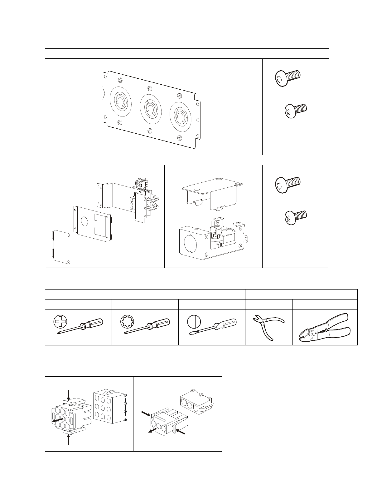
Package Contents
x4
suo1108a
x4
SRT011 - APC Smart-UPS SRT3000 VA PDU, 208 V (3) L6 - 30
PDU 4 Torx screws
1 ground screw
suo110 7a
SRT012 - APC Smart-UPS SRT 2200/3000 VA Output HW Kit
Output module Input module 4 Torx screws
1 ground screw
b
9
0
1
1
o
u
s
Required tools
All Mo d els SRT012
Philli ps screw driver T20 Torx screw d river Flat head screw driver Wir e cutter Wir e striper
Disconnect PDU Connectors
Smart-UPS On-Line SRT011/SRT012 3
Page 4

SRT011
The UPS and PDU models may vary in appearance from those depicted in the diagrams. The PDU
installation proc edure is similar for SR T011 models.
PDU UPS Models
SRT011 SRT3000XLT
SRT3000RMXLT
SRT3000RMXLT-NC
SRT3000XLW-IEC
SRT3000RMXLW-IEC
Remove standard PDU
b
0
1
1
1
o
u
s
x5
See “Disconnect PDU Connectors” on page 3.
a
1
1
1
1
o
u
s
Smart-UPS On-Line SRT011/SRT0124
Page 5

Install SRT011
a
2
1
1
1
o
u
s
b
3
1
1
1
o
u
s
x5
The SRT011 installation is comple te. See “Configure UPS for PDU Panel” on page 10.
Smart-UPS On-Line SRT011/SRT012 5
Page 6

SRT012
Thread
Wire range
The UPS and PDU models may vary in appearance from those depicted in the diagrams. The PDU
installation proc edure is similar for SR T012 models.
Wiring Specifications
CAUTION
DAMAGE TO EQUIPMENT OR PERSONNEL
• Adhere to all national and local electrical codes.
• Wiring must be performed by a qualified electrician.
• Use copper wire for hardwiring.
• Use snap in strain reliefs.
• The UPS must be wired into a branch cir cuit, equipped with a circui t bre aker rated as specified in the t ables below.
• Actual wire siz e must comply with required amp capaci ty and national and local electrical codes.
• Recommended input t erminal screw torque: 7 lbf-in (0. 8 Nm).
• Recommended output terminal screw torque: 10.6 lbf -i n (1.2 Nm).
• Recommended wire strip length: 7 mm - 8 mm
Failure to follow these instructions can result in equipment damage and minor or moderate injury
Recommended strain relief wire range and thread
Wire range Thread
10 ~ 14 mm (0.39” - 0.55“) PG16
Metric M25
SRT2200 and SRT3000 models
Input connectio ns Wire to L1, L2/ N ,
Output connections Wire to L1, L2/N,
Branch C i rcuit Overcurrent
Models
Rating / Building Circuit
Wire Size, typical
Breaker (CB ) Curren t Rating
SRT2200XLA/SRT2200RMXLA/SR T2200RMXLA-NC 20 A 12 AWG
SRT3000XLA/SRT3000RMXLA/SRT3000RMXLA-NC 30 A 10 AWG 4 mm
2.5 mm
2
SRT2200XLI/SRT2200RMXLI/SRT2200RMXLI-NC 16 A 12 AWG 2.5 mm
SRT3000XLI/SRT3000RMXLI/SRT3000RMXLI-NC 20 A 12 AWG 2.5 mm
SRT3000XLT/SRT3000RMXLT/SRT3000RMXLT-NC 20 A* / 2 pole 12 AWG 2.5 mm
SRT3000XLW-IEC/SRT3000RMXLW-IEC 20 A IEC; 20 A UL* / 2 pole 12 AWG 2.5 mm
CAUTION
RISK OF FIRE, RISK OF DAMAGE TO EQUIPMENT OR PERSONNEL
* Connect the UPS models only to a circuit provided with recommended maximu m b ranch circuit overcurrent protection in
accordance with the National Electrical Code, ANSI/NFPA 70 and the Canadian Electrical Code, Part I, C22.1.
Failure to follow these instructions can result in fire, equi pm ent damage and m inor or moderate injury.
2
2
2
2
2
Smart-UPS On-Line SRT011/SRT0126
Page 7

PDU UPS Models
u
o
1
1
1
4
a
SRT012 SRT2200XLI, SRT2200RMXLI, SRT2200RMXLI-NC, SRT2200XLA, SRT2200RMXLA,
SRT2200RMXLA-NC
SRT3000 XL T, SRT30 00RMXL T, SRT3000RMXLT -NC, SR T3 000XLI, SR T3000RMXL I, SR T3000RMXLI-NC,
SRT3000XLA, SRT3000RMXLA, SRT3000RMXLA-NC SRT 3000XLW-IE C, SRT3000RMXLW-IEC
Remove the screw securing the input and cut the wires from the input.
Note: Cut the wires farthest from the UPS.
XLI, XLW-IEC models
XLT, XLA models
s
a
5
1
1
1
o
u
s
Smart-UPS On-Line SRT011/SRT012 7
Page 8

Connect the UPS wires to the hardwire input box. Secure the hardwire input box to the UPS.
White/Blue
L1
L2/N
UPS
b
7
1
1
1
o
u
s
UPS
Black/Brown
Green/GreenYellow
Assemble hardwire input box.
b
6
1
1
1
o
u
s
Smart-UPS On-Line SRT011/SRT0128
Page 9

L1
L2/N
x2
o
1
1
2
0
b
x2
o
1
1
2
1
b
See “Disconnect PDU Connector s” on page 3.
a
8
1
1
1
o
u
s
a
9
1
1
1
o
u
s
Prepare SRT012
u
s
u
s
Smart-UPS On-Line SRT011/SRT012 9
Page 10

Install SRT012
x5
SRT012
PDU Model
SRT011
SRT012
Configure UPS for PDU Panel
Reconfigure the UPS, using the display interface, to work with the new PDU.
a
2
2
1
1
o
u
s
1. Reconnect internal RBC.
2. Reconnect the XLBP if installed.
3. Reconnect the UPS to utility power. Do not turn on the UPS output.
4. Configure the PDU once the display interface message is visible.
5. Navigate to the Menu Type. Change the Display Menu Type to Advanced.
Main Menu > Configuration > Display > Menu Type > Advanced.
6. Navigate to the PDU Model to configure the PDU.
Main Menu > Configuration > UPS > PDU Model
7. Select the appropriate PDU from the given options and press
Note: The Standar d PDU option is the factory default.
PDU options in SRT2200 UPS PDU option in SRT3000 UPS
PDU Model
Output Off
12
Output Off
12
OK button.
Customer support and warranty information is available at the A PC Web site, www.apc.com.
© 2016 APC by Schneider Electric. APC, the APC logo and Smart-UPS are owned by Schneid er
Electric Industries S.A.S. or their affiliated companies. All other trademarks are property of their
respec tive owners.
8. W ait for 10 seconds for the display interface to reboot.
9. Verify that PDU model is updated.
Display Navigation: Main Menu > Configuration > UPS > PDU Model
10.Turn on the UPS output.
EN 990-5648A
1/2016
 Loading...