

Page 1
Zelio Logic 2
Smart Relay
User Manual
SR2MAN01
11/2007
Page 2

Table of Contents
Safety Information . . . . . . . . . . . . . . . . . . . . . . . . . . . . . . . . . . . .7
About the Book . . . . . . . . . . . . . . . . . . . . . . . . . . . . . . . . . . . . . . . 9
Part I Initial Power up and Discovering . . . . . . . . . . . . . . . . . . 11
Chapter 1 Initial Power up and Discovering . . . . . . . . . . . . . . . . . . . . . . .13
Safety . . . . . . . . . . . . . . . . . . . . . . . . . . . . . . . . . . . . . . . . . . . . . . . . . . . . . . . . . 14
Presentation of the Smart Relay Front Panel . . . . . . . . . . . . . . . . . . . . . . . . . . . 17
Characteristics and Connections. . . . . . . . . . . . . . . . . . . . . . . . . . . . . . . . . . . . . 19
Control Keys on the Front Panel of the Smart Relay . . . . . . . . . . . . . . . . . . . . . 20
Examples. . . . . . . . . . . . . . . . . . . . . . . . . . . . . . . . . . . . . . . . . . . . . . . . . . . . . . . 23
Part II Functions Accessible from the Front Panel . . . . . . . . . 29
Chapter 2
Overview of the Functions Accessible from the Front Panel. . . . 31
Functions Accessible from the Front Panel of the Smart Relay . . . . . . . . . . . . . 31
Chapter 3 Input/Output Screen . . . . . . . . . . . . . . . . . . . . . . . . . . . . . . . . . .33
Inputs-Outputs Screen . . . . . . . . . . . . . . . . . . . . . . . . . . . . . . . . . . . . . . . . . . . . 34
TEXT and DISPLAY screen . . . . . . . . . . . . . . . . . . . . . . . . . . . . . . . . . . . . . . . . 36
Chapter 4 PROGRAMMING Menu . . . . . . . . . . . . . . . . . . . . . . . . . . . . . . . .39
Rules for Entering Ladder Diagrams . . . . . . . . . . . . . . . . . . . . . . . . . . . . . . . . . . 41
Method for Entering a Contact or Coil. . . . . . . . . . . . . . . . . . . . . . . . . . . . . . . . . 43
Entering a Link . . . . . . . . . . . . . . . . . . . . . . . . . . . . . . . . . . . . . . . . . . . . . . . . . . 45
Entry of Function Block Parameters . . . . . . . . . . . . . . . . . . . . . . . . . . . . . . . . . . 47
Deletion and Insertion of Diagram Lines . . . . . . . . . . . . . . . . . . . . . . . . . . . . . . . 49
Chapter 5 PARAMETERS Menu . . . . . . . . . . . . . . . . . . . . . . . . . . . . . . . . .51
PARAMETERS Menu . . . . . . . . . . . . . . . . . . . . . . . . . . . . . . . . . . . . . . . . . . . . . 51
Chapter 6 MONITORING Menu . . . . . . . . . . . . . . . . . . . . . . . . . . . . . . . . . .53
MONITORING Menu. . . . . . . . . . . . . . . . . . . . . . . . . . . . . . . . . . . . . . . . . . . . . . 53
Chapter 7 RUN/STOP Menu. . . . . . . . . . . . . . . . . . . . . . . . . . . . . . . . . . . . .55
RUN/STOP Menu . . . . . . . . . . . . . . . . . . . . . . . . . . . . . . . . . . . . . . . . . . . . . . . . 55
3
Page 3

Chapter 8 CONFIGURATION Menu . . . . . . . . . . . . . . . . . . . . . . . . . . . . . . 57
PASSWORD Menu . . . . . . . . . . . . . . . . . . . . . . . . . . . . . . . . . . . . . . . . . . . . . . . 58
FILTER Menu. . . . . . . . . . . . . . . . . . . . . . . . . . . . . . . . . . . . . . . . . . . . . . . . . . . . 61
Zx KEYS Menu . . . . . . . . . . . . . . . . . . . . . . . . . . . . . . . . . . . . . . . . . . . . . . . . . . 62
WATCHDOG CYCLE Menu. . . . . . . . . . . . . . . . . . . . . . . . . . . . . . . . . . . . . . . . . 63
Chapter 9 CLEAR PROGRAM Menu . . . . . . . . . . . . . . . . . . . . . . . . . . . . . 65
CLEAR PROG Menu. . . . . . . . . . . . . . . . . . . . . . . . . . . . . . . . . . . . . . . . . . . . . . 65
Chapter 10 TRANSFER Menu . . . . . . . . . . . . . . . . . . . . . . . . . . . . . . . . . . . . 67
TRANSFER Menu . . . . . . . . . . . . . . . . . . . . . . . . . . . . . . . . . . . . . . . . . . . . . . . . 67
Chapter 11 VERSION Menu . . . . . . . . . . . . . . . . . . . . . . . . . . . . . . . . . . . . . 73
VERSION Menu. . . . . . . . . . . . . . . . . . . . . . . . . . . . . . . . . . . . . . . . . . . . . . . . . . 73
Chapter 12 LANGUAGE Menu . . . . . . . . . . . . . . . . . . . . . . . . . . . . . . . . . . . 75
LANGUAGE Menu. . . . . . . . . . . . . . . . . . . . . . . . . . . . . . . . . . . . . . . . . . . . . . . . 75
Chapter 13 DEFAULT Menu . . . . . . . . . . . . . . . . . . . . . . . . . . . . . . . . . . . . . 77
FAULT Menu . . . . . . . . . . . . . . . . . . . . . . . . . . . . . . . . . . . . . . . . . . . . . . . . . . . . 77
Chapter 14 CHANGE DATE/TIME Menu. . . . . . . . . . . . . . . . . . . . . . . . . . . . 81
CHANGE DATE/TIME Menu . . . . . . . . . . . . . . . . . . . . . . . . . . . . . . . . . . . . . . . . 81
Chapter 15 CHANGE SUMMER/WINTER Menu. . . . . . . . . . . . . . . . . . . . . . 83
CHANGE SUMMER/WINTER Menu . . . . . . . . . . . . . . . . . . . . . . . . . . . . . . . . . . 83
Part III LD Language . . . . . . . . . . . . . . . . . . . . . . . . . . . . . . . . . . .85
Chapter 16 LD Language Elements . . . . . . . . . . . . . . . . . . . . . . . . . . . . . . . 87
Introduction . . . . . . . . . . . . . . . . . . . . . . . . . . . . . . . . . . . . . . . . . . . . . . . . . . . . . 88
Discrete Inputs. . . . . . . . . . . . . . . . . . . . . . . . . . . . . . . . . . . . . . . . . . . . . . . . . . . 89
Zx Keys . . . . . . . . . . . . . . . . . . . . . . . . . . . . . . . . . . . . . . . . . . . . . . . . . . . . . . . . 91
Auxiliary Relays . . . . . . . . . . . . . . . . . . . . . . . . . . . . . . . . . . . . . . . . . . . . . . . . . . 93
Discrete (DISCR) Outputs . . . . . . . . . . . . . . . . . . . . . . . . . . . . . . . . . . . . . . . . . . 98
Timers . . . . . . . . . . . . . . . . . . . . . . . . . . . . . . . . . . . . . . . . . . . . . . . . . . . . . . . . 101
Counters . . . . . . . . . . . . . . . . . . . . . . . . . . . . . . . . . . . . . . . . . . . . . . . . . . . . . . 111
Fast Counter . . . . . . . . . . . . . . . . . . . . . . . . . . . . . . . . . . . . . . . . . . . . . . . . . . . 118
Counter Comparators . . . . . . . . . . . . . . . . . . . . . . . . . . . . . . . . . . . . . . . . . . . . 128
Analog Comparators . . . . . . . . . . . . . . . . . . . . . . . . . . . . . . . . . . . . . . . . . . . . . 129
Clocks . . . . . . . . . . . . . . . . . . . . . . . . . . . . . . . . . . . . . . . . . . . . . . . . . . . . . . . . 134
Texts . . . . . . . . . . . . . . . . . . . . . . . . . . . . . . . . . . . . . . . . . . . . . . . . . . . . . . . . . 138
LCD Screen Backlighting. . . . . . . . . . . . . . . . . . . . . . . . . . . . . . . . . . . . . . . . . . 140
Change to Summer / Winter Time . . . . . . . . . . . . . . . . . . . . . . . . . . . . . . . . . . . 141
Modbus Inputs/Outputs . . . . . . . . . . . . . . . . . . . . . . . . . . . . . . . . . . . . . . . . . . . 143
Message . . . . . . . . . . . . . . . . . . . . . . . . . . . . . . . . . . . . . . . . . . . . . . . . . . . . . . 144
4
Page 4

Part IV Creating and Debugging an Application . . . . . . . . . . . 147
Presentation . . . . . . . . . . . . . . . . . . . . . . . . . . . . . . . . . . . . . . . . . . . . . . . . . . . 147
Chapter 17 Implementing a Basic Application . . . . . . . . . . . . . . . . . . . . .149
Presentation of Ladder Diagrams . . . . . . . . . . . . . . . . . . . . . . . . . . . . . . . . . . . 150
Using the Reverse Function . . . . . . . . . . . . . . . . . . . . . . . . . . . . . . . . . . . . . . . 152
Notation Used by the Smart Relay . . . . . . . . . . . . . . . . . . . . . . . . . . . . . . . . . . 155
Application: Implementing a Two-way Switch . . . . . . . . . . . . . . . . . . . . . . . . . . 157
Chapter 18 Debugging an Application . . . . . . . . . . . . . . . . . . . . . . . . . . . .165
Introduction . . . . . . . . . . . . . . . . . . . . . . . . . . . . . . . . . . . . . . . . . . . . . . . . . . . . 166
Dynamic Mode Ladder Diagrams . . . . . . . . . . . . . . . . . . . . . . . . . . . . . . . . . . . 168
Dynamic Mode Function Block Parameters . . . . . . . . . . . . . . . . . . . . . . . . . . . 170
Dynamic Mode Menus. . . . . . . . . . . . . . . . . . . . . . . . . . . . . . . . . . . . . . . . . . . . 171
Smart Relay Reaction to a Power Failure . . . . . . . . . . . . . . . . . . . . . . . . . . . . . 172
Chapter 19 Backup and Transfer of Ladder Diagrams" . . . . . . . . . . . . . .175
Saving and Transferring Ladder Diagrams . . . . . . . . . . . . . . . . . . . . . . . . . . . . 175
Chapter 20 Sample Application . . . . . . . . . . . . . . . . . . . . . . . . . . . . . . . . .177
Specifications . . . . . . . . . . . . . . . . . . . . . . . . . . . . . . . . . . . . . . . . . . . . . . . . . . 178
Specification Analysis . . . . . . . . . . . . . . . . . . . . . . . . . . . . . . . . . . . . . . . . . . . . 179
Implementing the Solution. . . . . . . . . . . . . . . . . . . . . . . . . . . . . . . . . . . . . . . . . 181
Part V Diagnostics . . . . . . . . . . . . . . . . . . . . . . . . . . . . . . . . . . . 185
Chapter 21 Diagnostics . . . . . . . . . . . . . . . . . . . . . . . . . . . . . . . . . . . . . . . .187
Smart Relay Messages . . . . . . . . . . . . . . . . . . . . . . . . . . . . . . . . . . . . . . . . . . . 188
Frequently Asked Questions . . . . . . . . . . . . . . . . . . . . . . . . . . . . . . . . . . . . . . . 189
Appendices . . . . . . . . . . . . . . . . . . . . . . . . . . . . . . . . . . . . . . . . . . . . . 191
Appendix A Compatibility . . . . . . . . . . . . . . . . . . . . . . . . . . . . . . . . . . . . . . . 193
Compatibility between the version of the programming software and the
version of the firmware on the smart relay . . . . . . . . . . . . . . . . . . . . . . . . . . . . 194
Compatibility between the memory cartridges and the version of the firmware
on the smart relay . . . . . . . . . . . . . . . . . . . . . . . . . . . . . . . . . . . . . . . . . . . . . . . 195
Index . . . . . . . . . . . . . . . . . . . . . . . . . . . . . . . . . . . . . . . . . . . . . 197
5
Page 5
Safety Information
Important Information
§
NOTICE
Read these instructions carefully, and look at the equipment to become familiar with the
device before trying to install, operate, or maintain it. The following special messages
may appear throughout this documentation or on the equipment to warn of potential
hazards or to call attention to information that clarifies or simplifies a procedure.
The addition of this symbol to a Danger or Warning safety label indicates
that an electrical hazard exists, which will result in personal injury if the
instructions are not followed.
This is the safety alert symbol. It is used to alert you to potential personal
injury hazards. Obey all safety messages that follow this symbol to avoid
possible injury or death.
DANGER
DANGER indicates an imminently hazardous situation, which, if not avoided, will
result in death or serious injury.
WARNING
WARNING indicates a potentially hazardous situation, which, if not avoided, can result
in death, serious injury, or equipment damage.
CAUTION
CAUTION indicates a potentially hazardous situation, which, if not avoided, can result
in injury or equipment damage.
SR2MAN01 11/2007 7
Page 6

Safety Information
PLEASE NOTE Electrical equipment should be installed, operated, serviced, and maintained only by
qualified personnel. No responsibility is assumed by Schneider Electric for any
consequences arising out of the use of this material.
© 2007 Schneider Electric. All Rights Reserved.
8
SR2MAN01 11/2007
Page 7
About the Book
At a Glance
Document Scope This manual describes the use of functions accessible from the front panel of the
smart relay.
This document is divided into 5 parts and addresses the following topics:
z Part I: Powering up and Discovering the Smart Relay
z General presentation of the smart relay
z Part II: Functions Accessible from the Front Panel
z Description of the interface and the menus of the smart relay
z Part III: LD Language
z Description of automation functions available for programming in LADDER
z Part IV: Creating, Debugging and Saving an Application
z Example of programming
z Presentation of tools for debugging and saving an application
z Part V: Diagnostics
z Help for finding solutions to operating problems
Validity Note The information in this manual applies only to smart relays of the Zelio 2 series.
User Comments We welcome your comments about this document. You can reach us by e-mail at
techpub@schneider-electric.com
SR2MAN01 11/2007 9
Page 8
Presentation
Initial Power up and Discovering
I
Subject of this
Section
What's in this
Part?
This section presents the operation and main characteristics of the smart relay.
This part contains the following chapters:
Chapter Chapter Name Page
1 Initial Power up and Discovering 13
SR2MAN01 11/2007 11
Page 9
Presentation
Initial Power up and Discovering
1
Subject of this
Chapter
What's in this
Chapter?
This chapter presents the operation and main characteristics of the smart relay.
This chapter contains the following topics:
Topic Page
Safety 14
Presentation of the Smart Relay Front Panel 17
Characteristics and Connections 19
Control Keys on the Front Panel of the Smart Relay 20
Examples 23
SR2MAN01 11/2007 13
Page 10

Initial Power up and Discovering
Safety
Preliminary
Advice
Preliminary advice and general safety precautions relating to installing smart relays:
z
Remember that only qualified personnel are authorized to implement the smart relay.
z Read this instruction sheet and the User Guide to learn the procedures prior to
installing, wiring, operating, maintaining of controlling the smart relay.
z The end user should keep this User Guide and the product instructions sheet.
z
Install the smart relay by following the instructions in the instruction bulletin and the User
Guide. Improper installation may result in failure or malfunction of the smart relay.
z Make the necessary ground and short circuit the connections.
z Check the operating conditions, as described in the User Guide. If you are unsure
of the technical characteristics, contact Schneider Electric.
z Fluctuations or variations in the power supply voltage should not exceed the
tolerance thresholds stated in the technical characteristics, as they may lead to
operating failures and potentially dangerous situations.
z Take any steps necessary to ensure that an application interrupted by a power
failure continues to operate correctly after restoring power and make sure also
that no dangerous situation whatsoever arises.
z Take any steps necessary to prevent involuntary activation of the relay.
z Automation and control devices must be installed in areas where they are
protected against any risk of involuntary activation.
z
Ensure that all connections to the control system meet applicable safety standards.
z
Ensure that you comply with all applicable standards for emergency stop systems in
order to avoid potentially dangerous situations. Ensure that releasing the emergency
stop system does not cause the automated system to suddenly restart.
z Install the smart relay only in environments described in the User Guide. Do not
use the smart relay in environments subject to excessive temperatures, elevated
relative humidity, condensation, corrosive gases, or excessive shocks.
z The smart relay should be used in "Pollution level 2" environments. This level
defines the effect of pollution on the insulation.
z Definition of level 2 Pollution: Only non-conductive pollution arises, except for
occasional temporary conductivity caused by condensation. Do not use smart
relays in environments lower than those specified in IEC Standard 60664-1.
z Use appropriate wires according to current and voltage requirements. Tighten the
screws of the terminal according to the specified torque.
z Use an IEC 60127 approved fuse, in conformity with the requirements for current
and voltage, to protect the power line and output circuits. This is not required
when a device including a smart relay is intended for Europe.
z Use an EU-approved switch. This is not required when a device including a smart
relay is intended for Europe.
14
SR2MAN01 11/2007
Page 11
Initial Power up and Discovering
DANGER
RISK OF ELECTRIC SHOCK, EXPLOSION OR ELECTRIC ARCING
Power off the smart relay prior to installing, removing, wiring, maintaining or
inspecting a smart relay system.
Failure to follow this instruction will result in death or serious injury.
WARNING
RISK OF EXPLOSION
Precautions:
z Compliant with standard CSA C22.2 No 213: This equipment is designed for
use in Class 1, Division 2, Groups A, B, C, D or in non-dangerous locations only.
Replacement of components may compromise the suitability to this specified
environment.
z Ensure that the power voltage and its tolerances are compatible with those of
the smart relay.
z Do not disconnect the equipment as long as the power supply has not been cut
off or the zone is not safe.
z This product contains a battery. Do not place the smart relay in fire.
Failure to follow this instruction can result in death, serious injury, or
equipment damage.
WARNING
RISK OF ELECTRIC SHOCK OR FIRE
Precautions:
z The smart relay is solely intended for installation in an enclosure. Do not install
the smart relay outside of an enclosure.
z Ensure that no metal fragment or wiring material falls into the enclosure of the
smart relay. Foreign bodies may lead to fire, material damage or malfunction.
Failure to follow this instruction can result in death, serious injury, or
equipment damage.
SR2MAN01 11/2007 15
Page 12
Initial Power up and Discovering
INVOLUNTARY OPERATION OF EQUIPMENT
Precautions:
z Power off the smart relay prior to installation, deinstallation, wiring, maintenance
or operation of the unit.
z The emergency stop and the locking circuits should be configured in the
software program of the smart relay.
z In the event of failure of the relays or transistors in the output modules of the
smart relay, the outputs should remain activated or deactivated. For output
signals that might lead to serious accidents, install a control circuit external to
the smart relay.
z Install the modules according to the environmental operation conditions
specified in the instruction bulletin.
z Do not attempt to dismantle, repair or modify the smart modules.
z Use an IEC 60127 approved fuse, in conformity with the requirements for
current and voltage, to protect the power line and output circuits.
Failure to follow this instruction can result in death, serious injury, or
equipment damage.
WARNING
16
WARNING
RISK OF UNEXPECTED OPERATION
Special case of the use of the SR2COM01 modem communication extension.
Sending commands may lead to modification of the status of smart relay outputs
or accidental enabling of controlled equipment.
It is important to:
z Know how the commands will affect the process or the controlled equipment,
z Take any preventive measures necessary to ensure safety when making
modifications.
Failure to follow this instruction can result in death, serious injury, or
equipment damage.
SR2MAN01 11/2007
Page 13
Initial Power up and Discovering
Presentation of the Smart Relay Front Panel
Introduction Smart relays are designed to simplify the electrical wiring of intelligent solutions. A
smart relay is very simple to implement. Its flexibility and its high performance allow
users to save significant amounts of time and money.
This User’s Guide is intended for people who do not have an in-depth knowledge of
automation systems and who would like to be able to implement smart relays.
Description of
the Smart Relay
Front Panel
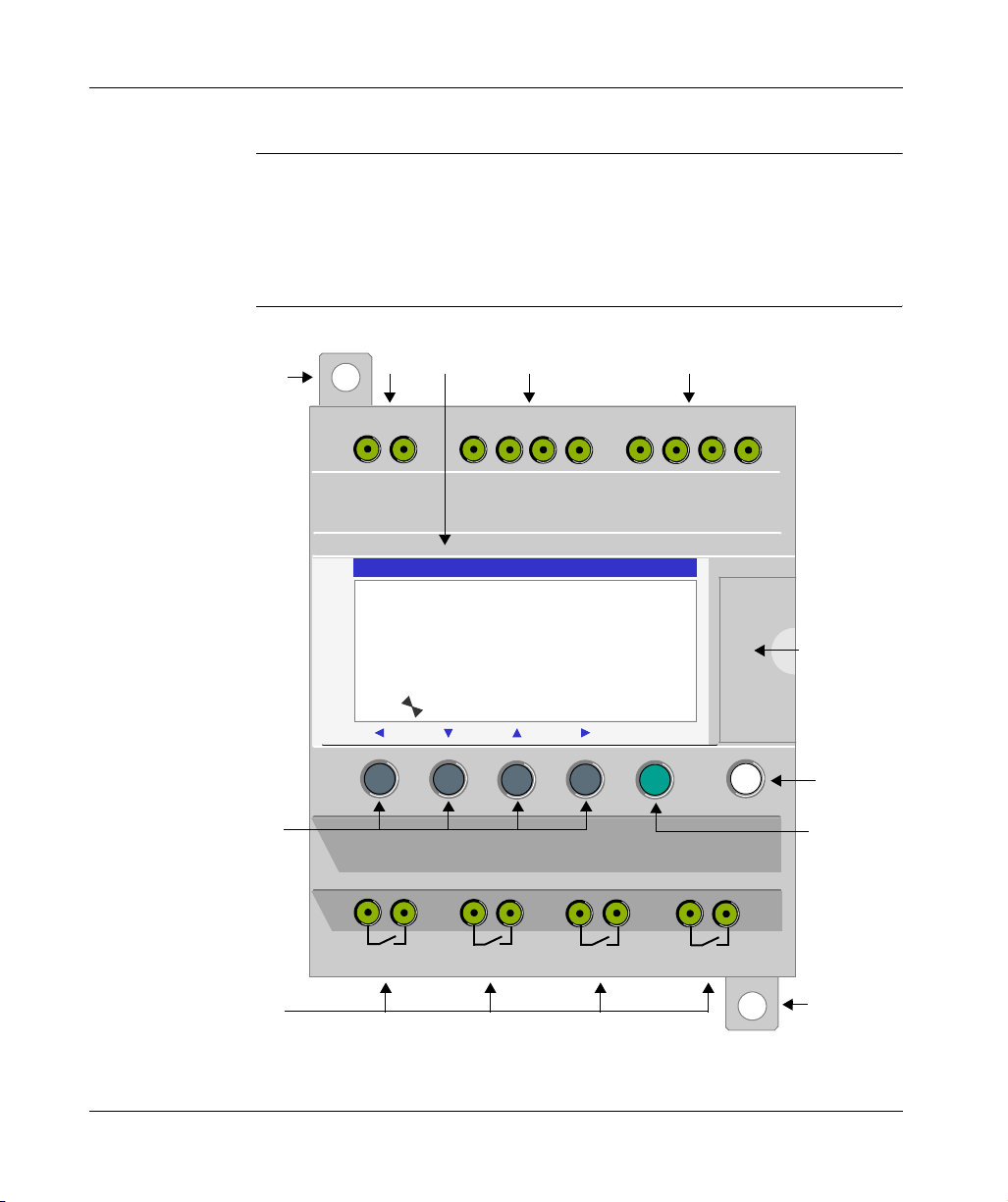
The illustration below presents the elements of the front panel of the smart relay:
1
23 4 5
+
24 VDC
-
I2I1 I4I3 ICIB
Inputs I1...I4
24 VDC
IEID
IB... IE
Analog or 24 VDC
SR2 B122BD
1 2 3 4 B C D E
S T O P L D
T H U 2 5 S E P 1 6 : 4 0
6
1 2 3 4
Menu / OK
7
10
Outputs
Q1 ... Q4: Relay 8A
8
2
1
Q1
9
SR2MAN01 11/2007 17
12
Q2
12
Q3
12
Q4
1
Page 14
Initial Power up and Discovering
Prompt Element
1 Retractable mounting feet.
2 Screw terminal block for the power supply.
3 LCD display, 4 lines, 18 characters.
4 Screw terminal block for discrete inputs.
5 Screw terminal block for analog inputs.
6 Slot for backup memory or PC connection cable.
7 Shift key (white).
8 Menu/OK key (green) for selection and confirmation.
9 Relay output screw terminal block.
10 Navigation keys (gray) or after configuring Z pushbuttons.
0-10 Volts, usable in discrete input mode depending on model.
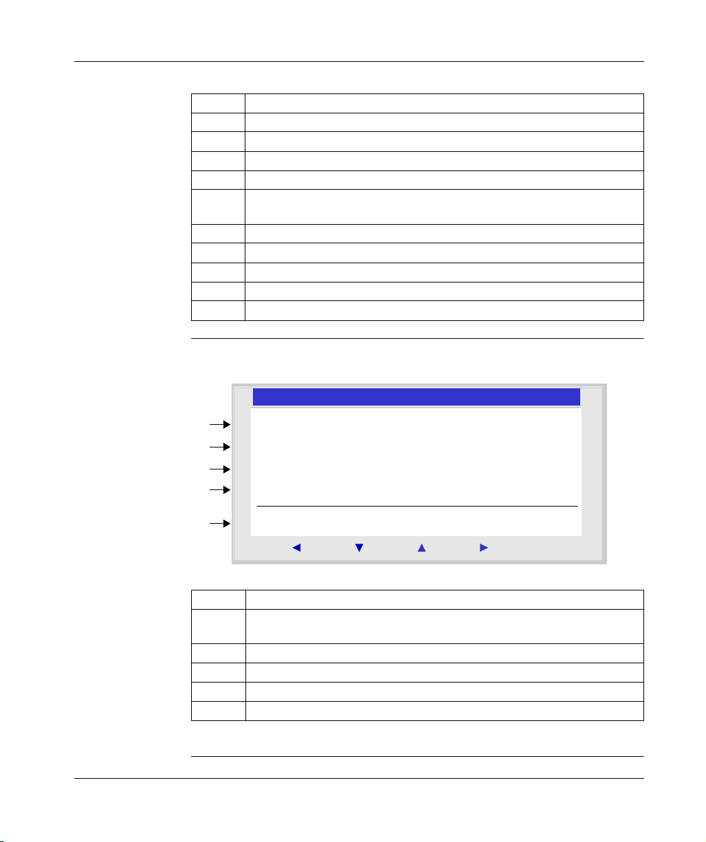
Description of
the LCD
The illustration below presents an example of LCD display elements when
displaying the INPUT-OUTPUT screen:
2
1
2
3
4
5
1 2 3 4 B C D E
S T O P L D
T H U 2 5 S E P 1 6 : 4 0
1 2 3 4
12 43
Menu / OK
Prompt Element
1 Input status* display (B...E represent the analog inputs, also may be used as
DISCR).
2 Display of the operating mode (RUN/STOP) and programming mode (LD/FBD).
3 Display of the date (day and time for products with clock).
4 Output status display.
5 Contextual menus / pushbuttons / icons indicating the operating modes.
* An ACTIVE input or output is displayed in reverse video.
18
SR2MAN01 11/2007
Page 15
Initial Power up and Discovering
Characteristics and Connections
Introduction Here is detailed information on the characteristics of DC smart relay connections.
Recommended
connection
Possible
Connection
Prohibited
Connection
It is recommended to connect the smart relay to a regulated DC power supply:
Regulated
220 V
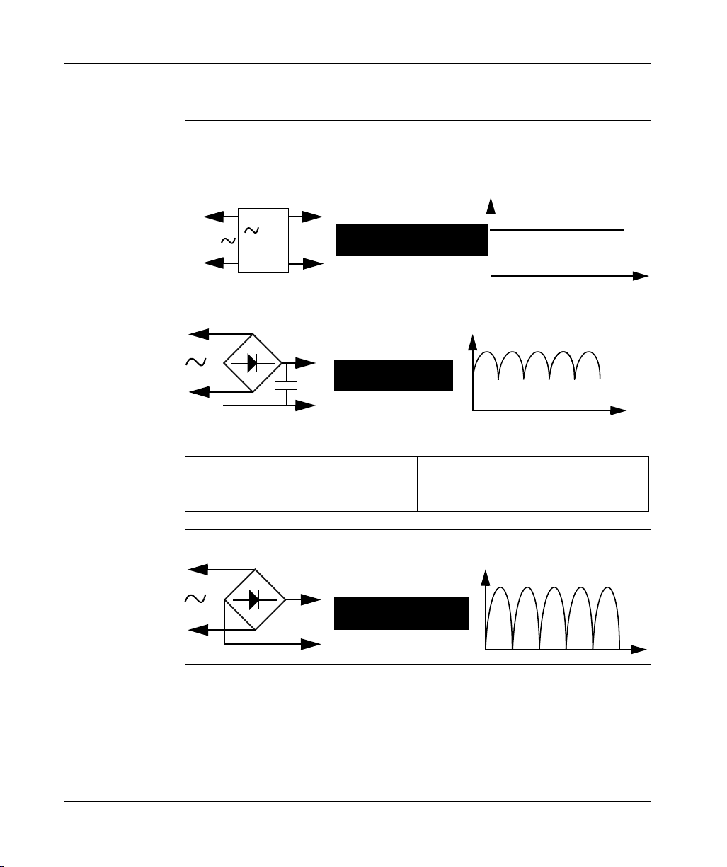
It is possible to connect the smart relay to a rectified filtered regulated power supply:
/=
ABL7R
24 V=
RECOMMENDED
Rectified and filtered
U max
POSSIBLE
Provided that it verify the following characteristics, according to the type of smart
relay:
SR2 ... BD SR2 ... JD
U max < 30 V
U min > 19.2 V
It is prohibited to connect the smart relay to a rectified non-filtered power supply:
U max < 14,4 V
U min > 10.4 V
U min
Rectified non filtered
PROHIBITED
SR2MAN01 11/2007 19
Page 16
Initial Power up and Discovering
Control Keys on the Front Panel of the Smart Relay
Description The keys located on the front panel of the smart relay are used to configure, program
and control the application and monitor the application's progress.
Illustration:
2
P R O G R A M M I N G
P A R A M E T E R S
R U N / S T O P
C O N F I G U R A T I O N
Menu / OK
Note: The LCD screen is lit for 30 seconds when the user presses any of the
buttons on the front panel.
Shift Key The Shift key is the white key located on the right side of the LCD screen.
When the Shift key is pressed, a contextual menu is displayed above the Z keys
(Ins, Del, Param, etc.).
Menu/OK Key The Menu/OK key is the green key located below the LCD screen on the right side.
This key is used for all confirmations: Menu, sub-menu, program, parameter, etc.
20
SR2MAN01 11/2007
Page 17

Initial Power up and Discovering
Zx Keys The Zx keys are the gray keys aligned from left (Z1) to right (Z4) and located under
the LCD. The arrows indicating the movement direction associated with navigation
are marked above the keys.
The navigation keys are used to move left or right, down or up.
The position on the screen appears as a flashing zone:
z Square for a position that corresponds to a contact (only in programming mode),
z Round for a link (only in programming mode).
Note: When the keys may be used for other actions apart from navigation, a
contextual menu bar is displayed (e.g.: 1, 2, 3 and 4 as Zx-type keys).
SR2MAN01 11/2007 21
Page 18
Initial Power up and Discovering
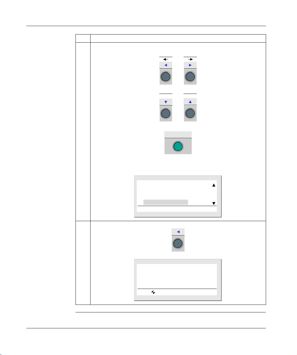
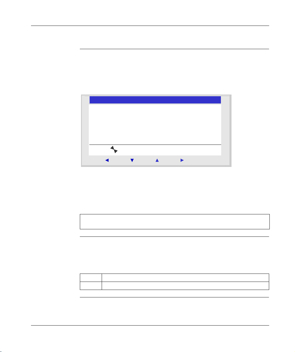
Contextual
Menus
When the cursor is placed on a modifiable parameter, if the Shift key is pressed, a
contextual menu appears.
Illustration:
ins. - Param+Del.
Menu / OK
Using the contextual menu functions:
z + / -: Used to scroll through the various possible values of the selected field (types
of inputs, outputs, automation functions, numbers, numerical values, etc),
z Ins.: Inserts a line,
z Del.: Deletes the selected element, or the entire line if it is empty,
z Param.: Displays the specific parameter screen for the automation function
(visible only if the automation function contains a parameter),
z ← ↑ ↓ →: Direction of the connection (visible only if the cursor is placed over a
link box),
z
1 2 3 4
: This line appears when the keys are used as Zx key-type inputs in a program.
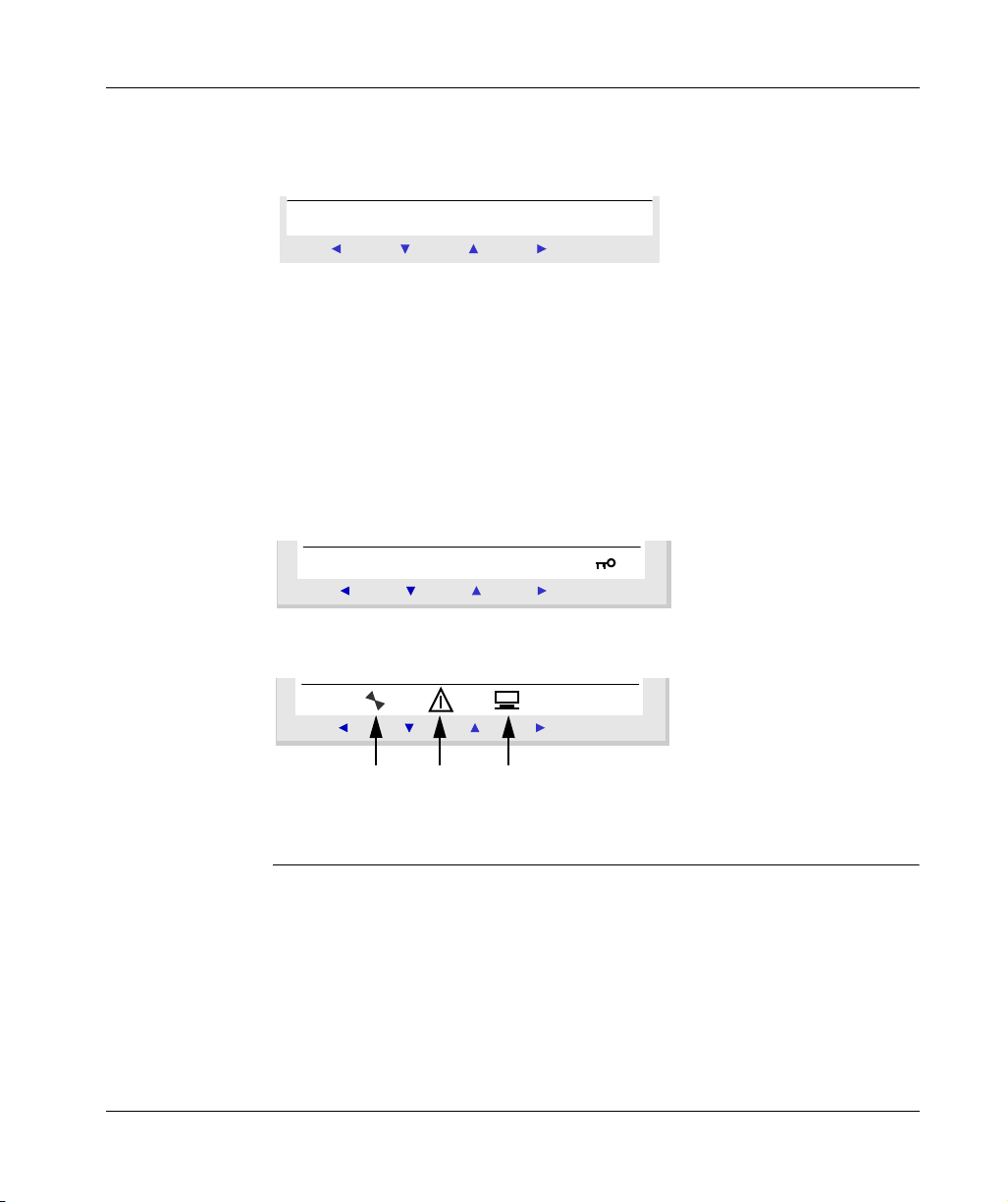
Illustration:
Menu / OK
The key indicates that the program is password-protected.
Illustration:
22
Menu / OK
1 2 3
1: Indicates the state of the smart relay. In RUN it is in motion, in STOP it is immobile.
2: Indicates that faults have appeared (see FAULT menu).
3: The smart relay is physically connected to the programming software.
SR2MAN01 11/2007
Page 19
Initial Power up and Discovering
Examples
Introduction We will now see two examples of how to use the smart relay’s keys.
Language
Selection
Example 1: Here are details on how to select the language of the smart relay:
Step Action
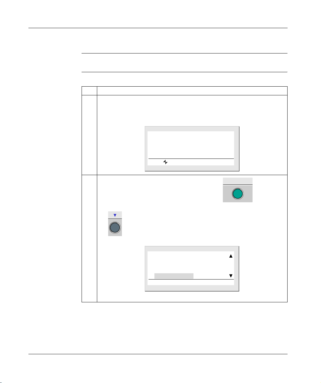
1 Powering up
On initial powering-up, the INPUT-OUTPUT screen is displayed (See: Inputs-Outputs
Screen, p. 34). By default, the selected language is English.
View:
1 2 3 4 B C D E
S T O P L D
F R I 2 5 N O V 1 6 : 4 0
1 2 3 4
2
From the INPUT-OUTPUT screen, enter the MAIN menu , then go to the
CONFIGURATION menu LANGUAGE, by pressing 7 times on the down navigation
key .
View:
C L E A R P R O G
T R A N S F E R
V E R S I O N
L A N G U A G E
Menu / OK
Note: the selected command flashes.
SR2MAN01 11/2007 23
Page 20
Initial Power up and Discovering
Step Action
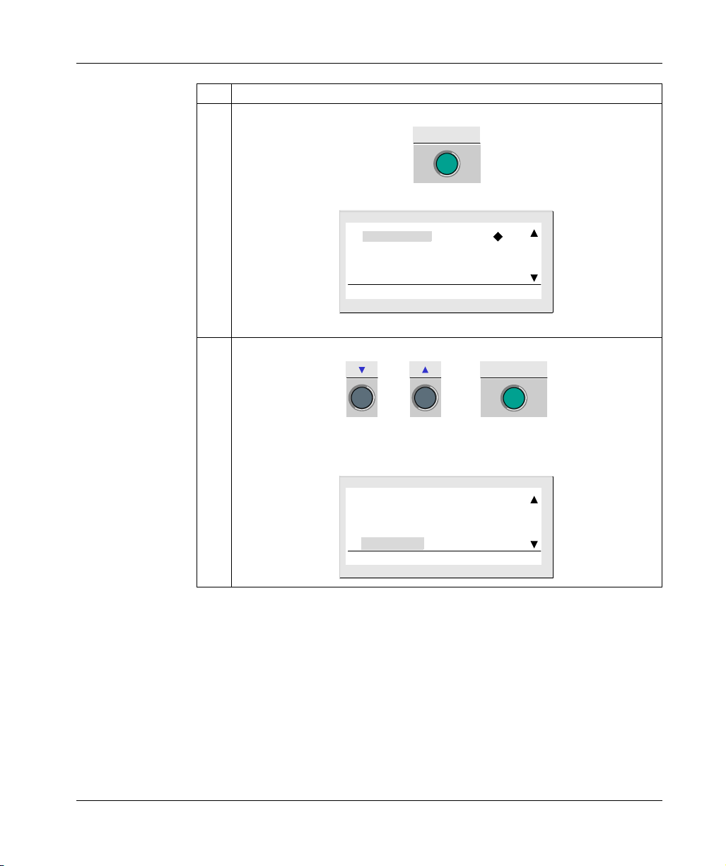
3 Enter in the language selection menu.
4 Select and confirm the language (the selection is shown in flashing text).
Menu / OK
View:
E N G L I S H
F R A N C A I S
D E U T S C H
I T A L I A N O
Note: The activated option flashes and it is also indicated by a black diamond.
Menu / OK
or then
The Menu/OK button is used to confirm the selection of the new language. The
display returns to the MAIN menu when the smart relay is in STOP mode.
View:
24
C L E A R P R O G
T R A N S F E R
V E R S I O N
L A N G U A G E
SR2MAN01 11/2007
Page 21
Initial Power up and Discovering
Step Action
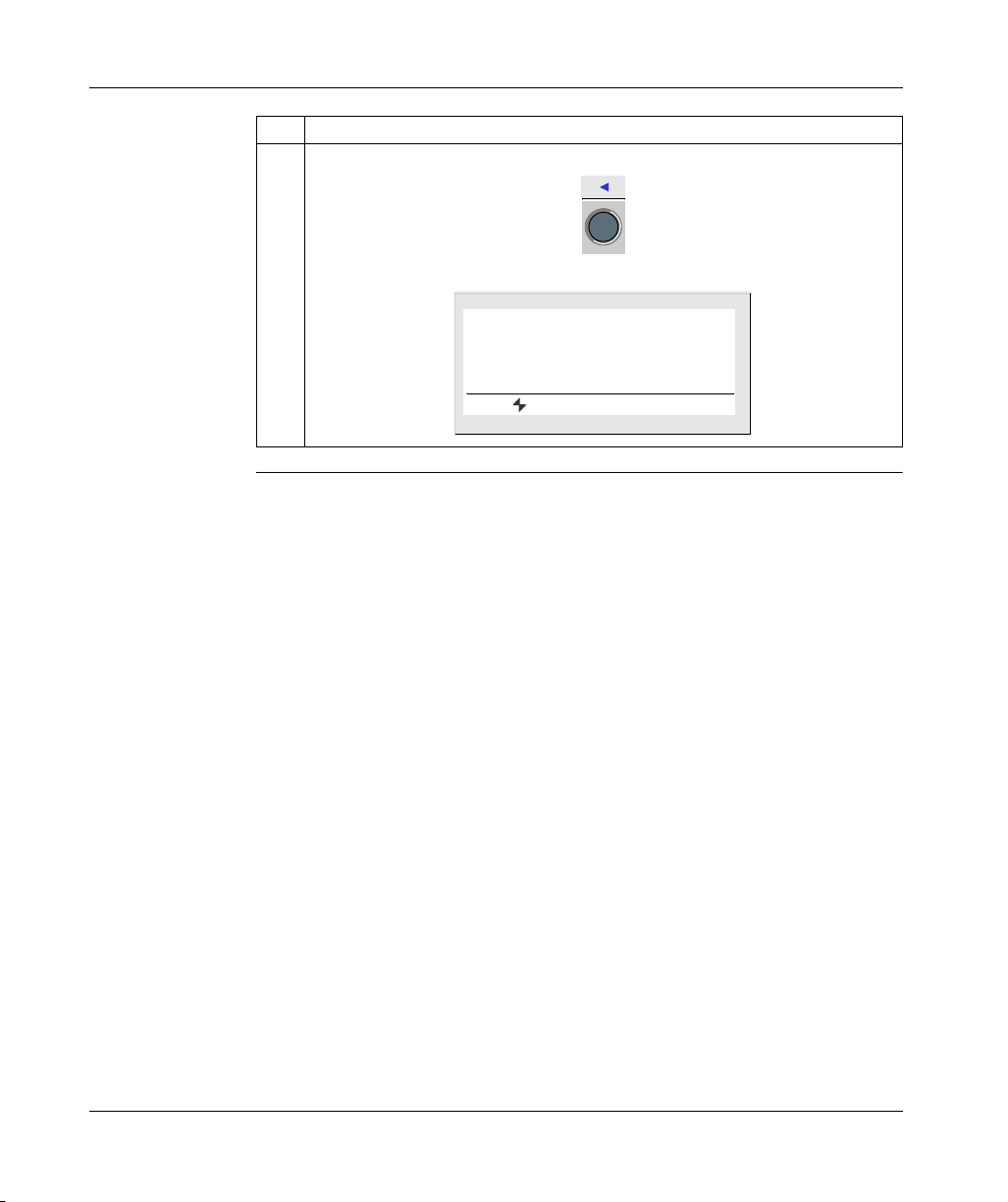
5 Return to the INPUT-OUTPUT screen using the left navigation key.
View:
1 2 3 4 B C D E
S T O P L D
F R I 2 5 N O V 1 6 : 4 0
1 2 3 4
SR2MAN01 11/2007 25
Page 22
Initial Power up and Discovering
Modification of
Date and Hour
Example 2: Here are details on procedure to follow to modify the date and time of
the initial power up or following a long lasting power failure.
Step Action
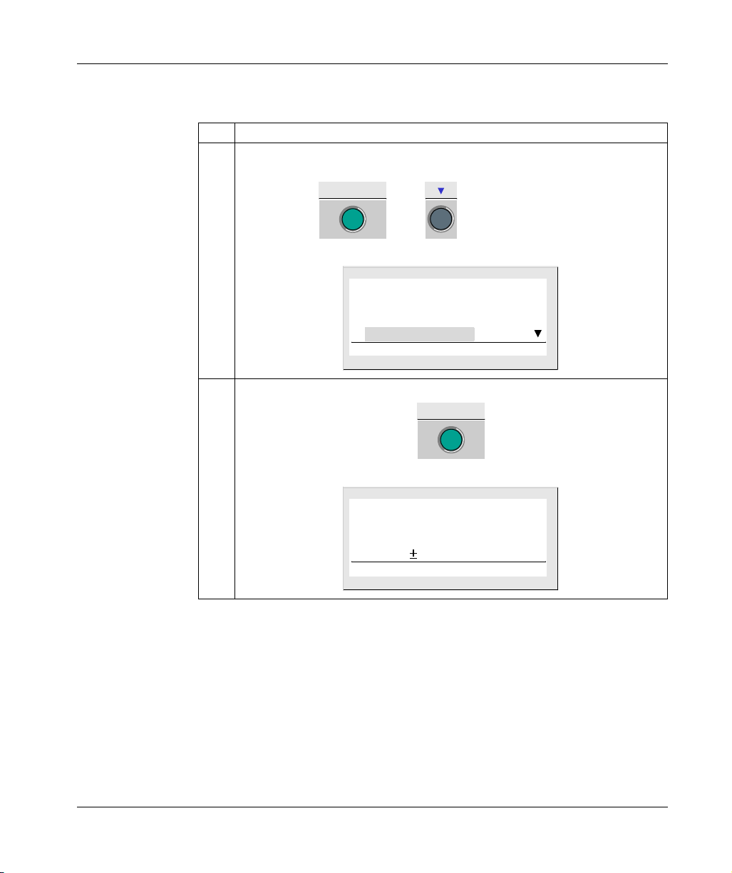
1 From the INPUT-OUTPUT screen, enter the MAIN menu, then go to the CHANGE D/
H menu:
Menu / OK
then
View:
V E R S I O N
L A N G U A G E
D E F A U L T
C H A N G E D / H
2 Enter the date and hour configuration menu:
9 times in LD mode
7 times in FBD mode
Menu / OK
View:
26
C H A N G E D / H
T H U 0 7 J U L 2 0 0 3
1 6 : 2 7 3 0 s
C A L 0 2 secs / WK
SR2MAN01 11/2007
Page 23
Initial Power up and Discovering
Step Action
3 Select the parameter to modify using the arrows (the selection is highlighted by the
blinking of the parameter):
or
Modify the parameter using the navigation keys:
-
+
or
Then confirm with the Menu/OK key:
Menu / OK
The Menu/OK button is used to confirm the modifications. The display returns to the
MAIN menu when the smart relay is in STOP mode).
View:
V E R S I O N
L A N G U A G E
D E F A U L T
C H A N G E D / H
4 Return to the INPUT-OUTPUT screen
View:
1 2 3 4 B C D E
S T O P L D
F R I 2 5 N O V 1 6 : 4 0
1 2 3 4
SR2MAN01 11/2007 27
Page 24
At a Glance
Functions Accessible from the Front Panel
II
Subject of this
Section
What's in this
Part?
This section describes the functions that can be accessed from the front panel of the
smart relay.
This part contains the following chapters:
Chapter Chapter Name Page
2 Overview of the Functions Accessible from the Front Panel 31
3 Input/Output Screen 33
4 PROGRAMMING Menu 39
5 PARAMETERS Menu 51
6 MONITORING Menu 53
7 RUN/STOP Menu 55
8 CONFIGURATION Menu 57
9 CLEAR PROGRAM Menu 65
10 TRANSFER Menu 67
11 VERSION Menu 73
12 LANGUAGE Menu 75
13 DEFAULT Menu 77
14 CHANGE DATE/TIME Menu 81
15 CHANGE SUMMER/WINTER Menu 83
SR2MAN01 11/2007 29
Page 25
Overview of the Functions Accessible from the Front Panel
Functions Accessible from the Front Panel of the Smart Relay
Description From the front panel of the smart relay, you may:
z Program (in LD mode),
z Configure,
z Control the application,
z Monitor the performance of the application.
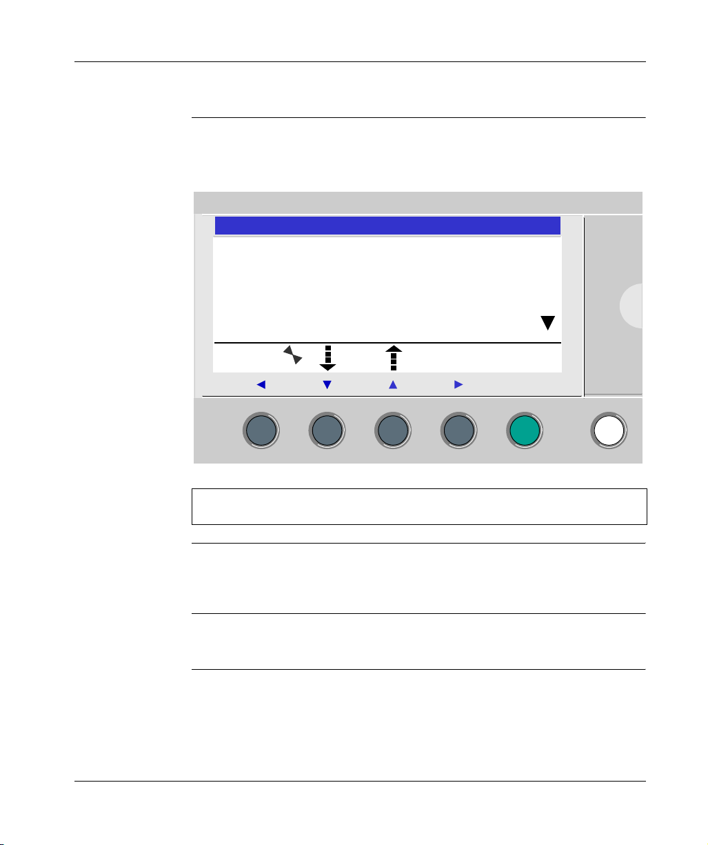
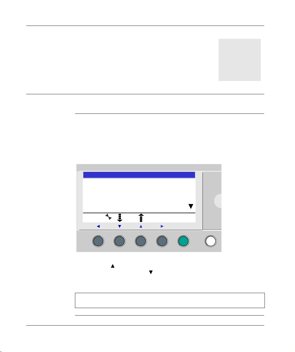
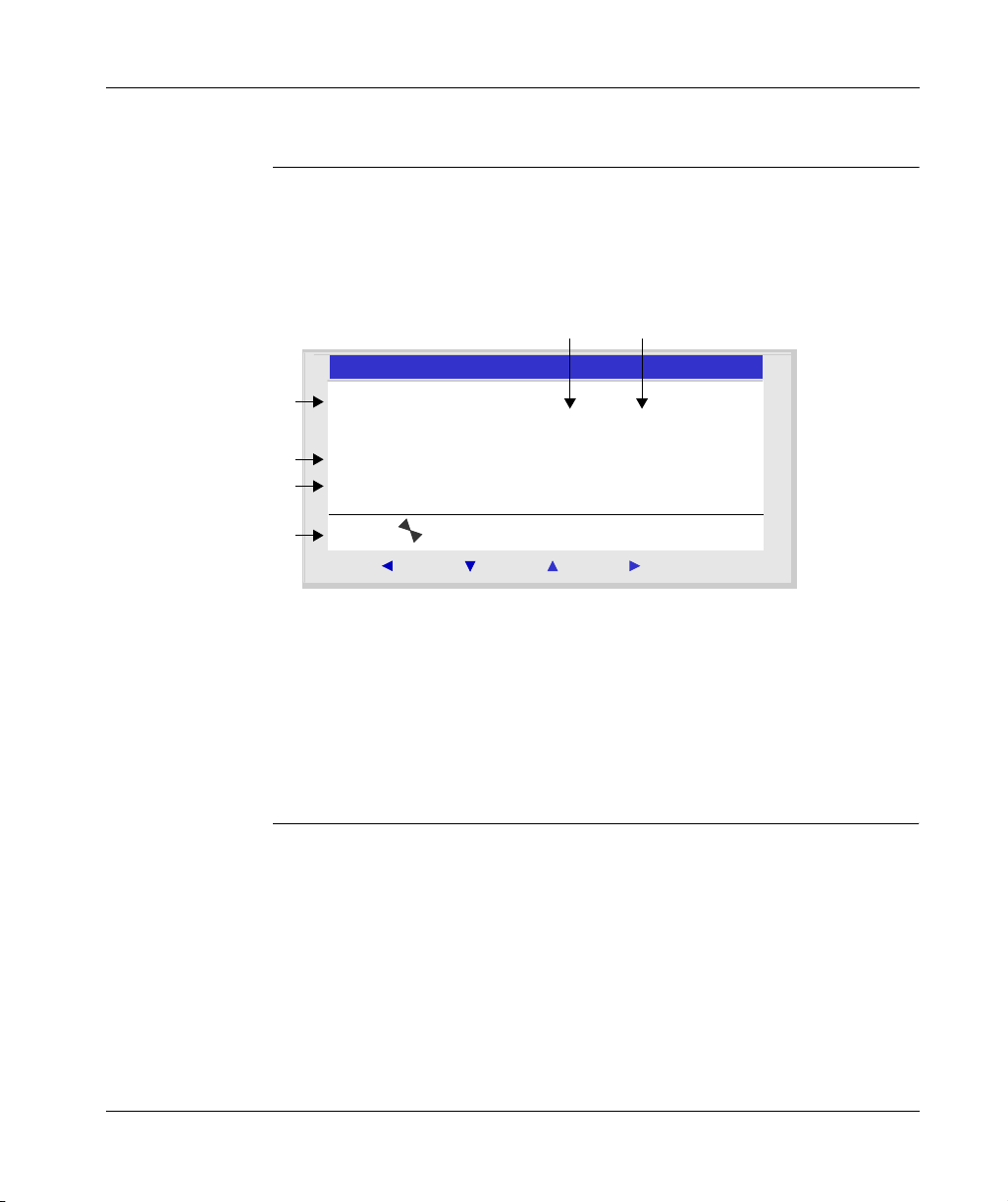
Illustration:
2
P R O G R A M M I N G
P A R A M E T E R S
R U N / S T O P
C O N F I G U R A T I O N
2
Menu / OK
The line flashes to indicate where you are positioned.
The up triangle on the right side of the LCD screen indicates that possible up
options exist. The down triangle indicates that possible down options exist.
To return to the previous menu, press left navigation key.
Note: The LCD screen is lit for 30 seconds when the user presses any of the
buttons on the front panel.
SR2MAN01 11/2007 31
Page 26
Overview of the Functions Accessible from the Front Panel
Managing Menus The inputs-outputs screen is displayed by default whether the mode be LD or FBD.
Pressing the Menu/OK key switches the display from the inputs-outputs screen to
the main menu.
The menu on the first row which is selected by default (flashing). The and
navigation keys can be used to place the cursor over the other menus.
Press the green Menu/OK key to display the screen corresponding to the selected
menu or to move onto the first sub-menu.
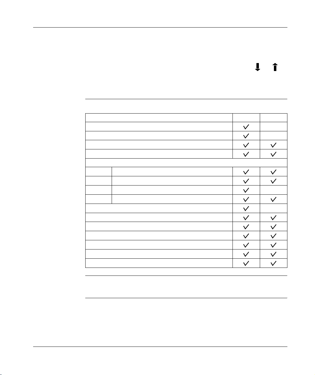
Differences
Between LD and
FBD Modes
Configuring
Extensions
Certain menus are specific to either LD or FBD mode.
Menu LD FBD
PROGRAMMING
MONITORING
PARAMETERS
RUN / STOP
CONFIGURATION
PASSWORD
FILTER
Zx KEYS
WATCHDOG CYCLE
CLEAR PROG.
TRANSFER
VERSION
LANGUAGE
FAULT
CHANGE D/T
CHANGE SUMM/WINT
Extensions added to the smart relay may only be configured from the programming
software. See on-line help of the programming software for more information.
32
SR2MAN01 11/2007
Page 27
At a Glance
Input/Output Screen
3
Subject of this
Chapter
What's in this
Chapter?
This chapter describes the characteristics of the input-output screen.
This chapter contains the following topics:
Topic Page
Inputs-Outputs Screen 34
TEXT and DISPLAY screen 36
SR2MAN01 11/2007 33
Page 28
Input/Output Screen
Inputs-Outputs Screen
Description The inputs-outputs screen is the highest-level interface. It is displayed by default,
when no (TEXT or DISPLAY) display function is active and regardless of:
z The programming type: LD or FBD,
z the mode: STOP or RUN.
Illustration:
2 3
2
1
1 2 3 4 5 6
S T O P L D
4
M O N 2 2 S E P 1 5 : 5 1
5
1 2 3 4
6
2
Menu / OK
The inputs-outputs screen can be used to view:
1. the state of the inputs: 1 to 9, A to P,
2. The mode used: LD/FBD,
3. The Operating mode: RUN / STOP,
4. The date and time for products with a clock,
5. the state of outputs: 1 to 9, A to G,
6. Z push buttons: 1 to 4.
In Simulation mode or Monitoring mode when the program is in RUN, the active
states of the inputs and outputs are indicated in reverse video.
34
SR2MAN01 11/2007
Page 29

Input/Output Screen
Access to the
Main Menu
Pressing the Menu/OK key switches the display from the inputs-outputs screen to
the main menu:
z PROGRAMMING (LD STOP mode),
z MONITORING (LD RUN mode),
z PARAMETERS,
z RUN / STOP,
z CONFIGURATION (STOP mode),
z CLEAR PROG. (LD STOP mode),
z TRANSFER (STOP mode),
z VERSION,
z LANGUAGE,
z FAULT,
z CHANGE D/T,
z CHANGE SUMM/WINT.
The display automatically returns to the inputs-outputs menu on exiting all other
menus and sub-menus.
SR2MAN01 11/2007 35
Page 30
Input/Output Screen
TEXT and DISPLAY screen
Description The display functions are used to display text or numerical values (current value,
preset value, etc.) on the LCD display instead of the INPUTS-OUTPUTS:
z In LD mode: A TEXT function is active,
z in FBD mode: A DISPLAY function is active.
Illustration:
2
V a l u e c o u n t e r 1
C 1 C = 0 0 0 0 1
D a t e
2 8 / 1 1 / 2 0 0 3
2
Menu / OK
If several display functions are active simultaneously:
z In LD mode: The highest block number is displayed. There are 16 TEXT-type
blocks numbered from 1 to 9 then from A to G,
z In FBD mode: The superposition of all of the FBD DISPLAY screens is displayed,
for up to 32 blocks. If more than 32 FBD DISPLAY blocks are active, the screens
of the 32 FBD DISPLAY blocks with the lowest numbers are superposed.
Switching
Between the
Screens
36
Note: The display functions are programmable only from the programming
software (see the on-line help for the programming software for more information).
Switching between the screens
It is however possible to go from the TEXT (LD) or DISPLAY (FBD) screen to the
INPUTS-OUTPUTS screen and vice-versa.
To do this, proceed as follows:
Step Step
Action Press and hold down the Shift key and press the Menu/OK key.
SR2MAN01 11/2007
Page 31

Input/Output Screen
Modify Displayed
Values
In RUN mode, when the TEXT / DISPLAY screen is displayed, it is possible to
modify, from the front panel, the displayed values whose modification was
authorized in the block function parameters window.
To do this, proceed as follows:
Step Step
Action Press the Shift key (white key) to display the contextual menu.
Result: Param is displayed at the bottom of the screen.
2
Press the key (without releasing the Shift key) to display the contextual menu.
Result: The parameter which can be modified flashes and the following contextual
menu is displayed:
-+
Menu / OK
3
Select the parameter to be modified using the navigation keys and from the
contextual menu (the value which are available for modification flash).
4
Modify the parameter value with the + ( ) and - ( ) keys from the contextual menu.
5 Confirm the changes by pressing the Menu/OK key.
Result: The display returns to the INPUTS-OUTPUTS screen or the TEXT /
DISPLAY screen.
SR2MAN01 11/2007 37
Page 32

Presentation
PROGRAMMING Menu
4
Subject of this
Chapter
This chapter describes the characteristics of the PROGRAMMING menu specific to
LD mode / smart relay in STOP mode.
This function lets the user enter the ladder diagrams that will work on the smart relay.
This program is written only using a ladder diagram LD.
Illustration:
2
I1 RT1
I2
I1 M3 T1 SM1
TT1
Menu / OK
Note: The smart relays to which have been added an Input/Output extension are
programmable only in FBD mode from the programming software.
See on-line help of the programming software for more information.
SR2MAN01 11/2007 39
Page 33

PROGRAMMING Menu
What's in this
Chapter?
This chapter contains the following topics:
Topic Page
Rules for Entering Ladder Diagrams 41
Method for Entering a Contact or Coil 43
Entering a Link 45
Entry of Function Block Parameters 47
Deletion and Insertion of Diagram Lines 49
40
SR2MAN01 11/2007
Page 34

Rules for Entering Ladder Diagrams
Description A smart relay allows you to enter 120 line Ladder diagrams.
The smart relay’s display screen is used to display these lines, 4 at a time, in the
following manner:
1
2
3
I1-H1-C1-M1-T2-CC1
I2
Z1 ---------- Z3
4
Prompt Element
1 Column reserved for contacts (conditions).
2 Column reserved for contacts (conditions) and for links.
3 Column reserved for coils (actions).
4 Column reserved for links.
PROGRAMMING Menu
Each line comprises 5 fields each with 2 characters reserved for contacts
(conditions). The 4 central columns can also accept links. The last three-character
column is reserved for coils (actions).
Links must be entered between the contact and coil columns.
A ladder diagram is entered into the smart relay using the front panel keys (see
Control Keys on the Front Panel of the Smart Relay, p. 20).
SR2MAN01 11/2007 41
Page 35

PROGRAMMING Menu
Data Entry Rules Make sure you respect the following rules when you enter a ladder diagram:
Rules Incorrect Correct
Each coil must only be
entered once in the right
hand column
I1-------------[Q1
I2-I3----------TT1
T1-------------[Q1
Z1
I1-------------[Q1
T1
I2-I3----------TT1
Z1
Elements used as
contacts may be entered
as many times as
necessary in the 5 left
hand columns.
Links must always run
from left to right.
I1-I2-I3
--
I1-------------TT1
T1-------------[Q1
I3-T1----------[M2
I1-M2----------[Q2
I1-I2-I3-------[M1
M1----I4-I5-I6-[Q1
I4-I5-I6-[Q1
If S coils (SET) are used in
a diagram, also use an R
(Reset) coil.
If no R (Reset) coils are used,
the corresponding coil will
always be set to 1.
An R (Reset) coil must be used
for reset purposes.
Note: Smart relays run programs from top to bottom and from left to right.
42
SR2MAN01 11/2007
Page 36

Method for Entering a Contact or Coil
Description
Note: Accessible only in LD mode / smart relay in STOP mode.
This section describes the procedures for performing the following operations:
z Entering an element,
z Modifying an element,
z Deleting an Element.
This is valid for : contact or coil elements, whether the parameters can be set or not.
PROGRAMMING Menu
Entering an
Element
When entering an element, the following rules must be observed:
z Contact: In any column except the last,
z Coil: Only in the last column.
The presence of a square, flashing cursor means an element can be inserted.
Entry procedure:
Step Action
1 Place the flashing cursor at the required location.
The navigation keys can be used move the cursor in the direction of the arrows on
the navigation keys .
Illustration:
2 Press the Shift key to display the contextual menu.
Illustration:
ins. - + Del.
Menu / OK
By simultaneously pressing Shift and one of the (- and +) keys, the first letter
of the element is inserted: I for a contact and Q for a coil, followed by the number 1.
3
Choose the type of element desired by pressing simultaneously on
makes the different types of elements scroll down cyclically, in the following order:
z For the contacts: I, i, Z, z, M, m, Q, q, T, t, C, c, K, k, V, v, A, a, H, h, W, w, S, s.
z For the coils: M, Q, T, C, K, X, L, S.
See the chapterLD Language Elements, p. 87.
Shift
and +or-. This
SR2MAN01 11/2007 43
Page 37

PROGRAMMING Menu
Step Action
4
Release the Shift key to have access to the navigation keys: .
Pressing the key places the cursor over the corresponding number 1.
5 Simultaneously hold down the Shift and + keys to increment the number of the
element (2, 3, 4,..., 9, A, etc.).
Note: The numbers for functional blocks are limited to the number of blocks of the
type available in the smart relay. In the case of extensible smart relays, the inputs and
outputs numbers are used to program the extension to maximum size.
In entering a contact, once this step is completed, the entry is terminated.
In entering a coil, you must additionally select the function of the coil.
6
Release the Shift key to have access to the navigation keys: .
7 Steps 7 to 9 are only necessary when entering a coil.
Position the cursor on the function of the coil by pressing twice on the key.
8 Select the desired function by pressing simultaneously on the Shift key and the +
or - key. This will scroll through the different coil functions available.
9
Release the Shift key to have access to the navigation keys: .
Note: Confirming some function block coils will bring-up a function block parameter
setting screen.
Modifying an
element,
To modify an existing control diagram element, simply:
z Position the pointer over the element to modify: Step 1 in the previous table,
z Select the desired new element: Steps 3 to 6.
Initialization Status of contacts on program initialization:
z A contact in normally-open mode (direct state) is inactive,
z A contact in normally-closed mode (reverse state) is active,
Deleting an
Element
To delete an element, simply:
z Place the cursor over the element to delete: Step 1,
z Simultaneously press the Shift and Menu/OK keys.
Two scenarios are possible, depending on the position of the cursor at the time of the deletion:
z Cursor over an element: the element is deleted,
z Cursor over an empty position of the line: the whole line is deleted.
Note: Generally, the deleted element must be replaced by a link.
44
SR2MAN01 11/2007
Page 38

Entering a Link
Description
Note: Accessible only in LD mode / smart relay in STOP mode.
This section describes the procedures for performing the following operations:
z Entering links between elements,
z Deleting links between elements,
z Replacing a link with a contact.
Entering a Link Links are entered exclusively using the round flashing cursor.
Entry procedure:
Step Action
1 Place the flashing cursor at the required location.
The navigation keys can be used move the cursor in the direction of the arrows on the
navigation keys .
Illustration:
PROGRAMMING Menu
2 Press the Shift key to display the contextual menu.
Illustration:
Del.
Menu / OK
3 Trace connections by simultaneously pressing the Shift key and the navigation keys:
←↑↓→.
Shift and → to trace a connection to the position of the next contact or to the coil at
the end of the line.
Shift and ↑↓ to trace perpendicular connections to the previous or next line.
4
Release the Shift key to have access to the navigation keys: .
5 Repeat the operation as many times as necessary to link the elements together
according to your requirements.
SR2MAN01 11/2007 45
Page 39

PROGRAMMING Menu
Modifying a Link To modify an existing link, simply:
z Place the cursor over the link to modify: step 1
z Modify the link: Steps 2 to 5.
Deleting a Link To delete a link, simply:
z Place the cursor over the element to delete: step 1.
z Simultaneously press the Shift and Menu/OK keys.
Two scenarios are possible, depending on the position of the cursor at the time of
the deletion:
z Cursor over a link: The link is deleted,
z Over an empty position of the line: The whole line is deleted.
Replacing a Link
with a Contact
To replace a link with a contact, simply:
z Place the cursor (flashing square) over the link to transform: step 1.
z Follow the element entry (see Method for Entering a Contact or Coil, p. 43)
procedure: Steps 3 to 6.
46
SR2MAN01 11/2007
Page 40

Entry of Function Block Parameters
Description
Note: Accessible only in LD mode / smart relay in STOP mode.
When entering a control diagram, the parameters of the configurable automation
functions must be completed.
The automation functions with parameters are the following:
z Auxiliary relays (see Auxiliary Relays, p. 93) (latching),
z Discrete Outputs (see Discrete (DISCR) Outputs, p. 98) (latching),
z Clocks (see Clocks, p. 134),
z Analog Comparators (see Analog Comparators, p. 129),
z Timers (see Timers, p. 101),
z Counters (see Counters, p. 111),
z Fast counters (see Fast Counter, p. 118).
PROGRAMMING Menu
Accessibility of
parameters
Function block parameter setting can be accessed:
z When entering the command diagram line,
z From the PARAMETERS menu if the block has not been padlocked.
SR2MAN01 11/2007 47
Page 41

PROGRAMMING Menu
Entering
Parameters on
Creation of the
Block
Modifying the
Parameters of
Existing Blocks
Parameters are entered in the same way, whatever the parameters screen:
Step Action
1 Enter the desired automation function: Step 1 of the element entry (see Method for
Entering a Contact or Coil, p. 43) procedure.
When the function has parameters, Param appears in the contextual menu (when the
Shift key is pressed).
Illustration:
ins. - Param+Del.
Menu / OK
2
Press and hold down the Shift key and press on Param (key ).
Result: The function’s parameter screen appears.
3
Use the navigation keys to move to the cursor over the modifiable parameters: .
4 Modify the value of the parameter using the + and - keys, holding down Shift.
5
Confirm the modifications by pressing
Confirm again by pressing the Menu/OK key to save.
Menu/OK
, which will open the confirmation window.
To modify the parameters of an existing element, simply:
Step Action
1 Use the navigation keys to move the cursor over the element to modify: step 1 of the
element entry (see Method for Entering a Contact or Coil, p. 43) procedure.
2
At the same time, hold down
3 Carry out steps 3 to 5 above.
Shift
and the
Param
key to open the parameter window.
48
SR2MAN01 11/2007
Page 42

Deletion and Insertion of Diagram Lines
Deletion
Note: Accessible only in LD mode / smart relay in STOP mode.
Diagram lines are deleted line-by line. The procedure is the following:
Step Action
1 Place the cursor over the line to delete.
2 Delete all the elements in the line (see Method for Entering a Contact or Coil, p. 43):
(Links, contacts and coils) to obtain an empty line.
3 Press the Shift key to display the contextual menu.
Illustration:
ins. - +Del.
Simultaneously pressing Shift and Del opens the confirmation window.
4 Confirm by pressing Menu/OK.
Note: It is possible to delete all diagram lines contained in the smart relay. In order
to do this, select the CLEAR PROG. option from the main menu, and confirm the
deletion of all the control diagram lines.
PROGRAMMING Menu
Menu / OK
Insertion The procedure is the following:
Step Action
1 Place the cursor over the line located immediately below the line to create.
2 Press the Shift key to display the contextual menu.
3 Press the Ins key (while holding down the Shift key) to create the line.
SR2MAN01 11/2007 49
Page 43

PARAMETERS Menu
5
PARAMETERS Menu
Description This menu is used to enter and modify the application parameters directly on the
screen using the smart relay keys. This function can be accessed in the two modes:
LD and FBD, but the contents will be specific to the mode used.
If there are non-locked parameters to display they are listed in the window;
otherwise a NO PARAMETER message appears.
LD mode Functions with parameters in LD mode:
z Auxiliary relays (see Auxiliary Relays, p. 93) (latching),
z Discrete Outputs (see Discrete (DISCR) Outputs, p. 98) (latching),
z Clocks (see Clocks, p. 134),
z Analog Comparators (see Analog Comparators, p. 129),
z Timers (see Timers, p. 101),
z Counters (see Counters, p. 111),
z Fast counter (see Fast Counter, p. 118).
Only those functions used in the program and with parameters are listed in the
PARAMETERS menu.
SR2MAN01 11/2007 51
Page 44

PARAMETERS Menu
FBD mode Functions with parameters in FBD mode:
z Numerical Constant-Type Inputs,
z Clocks,
z Gain,
z Timers: TIMER A/C, TIMER B/H, TIMER Li,
z Counters: PRESET COUNT,
z Fast counter,
z CAM block.
To access the parameters of the FBD blocks, you must know end enter the block
number. This number appears in the programming software on the wiring sheet at
the top right corner of the block.
Only those functions used in the program and with parameters are listed in the
PARAMETERS menu.
Parameter
Modification
Parameters in
RUN Mode
Parameter modification procedure:
Step Action
1 Place the cursor over the PARAMETERS menu in the main menu (PARAMETERS
flashing) and confirm by pressing the Menu/OK button.
Result: The parameters window opens to the first parameter.
2 Select the function to modify.
To access the required function, scroll through the function block numbers
(navigation keys and ) until you reach the right one.
3 Select the parameter to modify.
The and keys are used to place the cursor over the parameter to modify.
4
Modify the parameter using the + and - keys ( and ) of the contextual menu.
5 Confirm the modifications by pressing Menu/OK, which will open the confirmation
window.
6 Confirm again twice by pressing Menu/OK to save.
Result: The display returns to the INPUTS-OUTPUTS screen in RUN mode and to
the MAIN menu in STOP mode.
It is therefore possible to modify parameters in RUN mode dynamically as long as
they are not locked.
The modifications can be made:
z From the PARAMETERS (see PARAMETERS Menu, p. 51) menu,
z From the MONITORING (see MONITORING Menu, p. 53) (LD) menu: Move the
pointer over the function to be modified using the navigation keys and open the
parameters window from the contextual menu (Shift key).
52
SR2MAN01 11/2007
Page 45

MONITORING Menu
MONITORING Menu
6
Description
Note: Accessible only in LD mode / smart relay in RUN mode.
MONITORING mode can be used to obtain a dynamic view of the state of the smart
relay inputs/outputs.
In this mode the wiring diagram appears as it does in the PROGRAMMING (see
PROGRAMMING Menu, p. 39) menu (smart relay in STOP mode), but appear in
reverse video when inputs or outputs are activated (white on black background).
Illustration:
1 1
I -i2----------[Q
IB-------------TT1
T1-------------[Q2
H1-------------[M1
This mode is also used to dynamically modify the values of automation function
parameters if these are not locked.
SR2MAN01 11/2007 53
Page 46

MONITORING Menu
Parameter
Modification
To modify the parameters, proceed as follows:
Step Action
1 Use the navigation keys to move the cursor over the element to modify: Step 1 of the
element entry (see Method for Entering a Contact or Coil, p. 43) procedure.
2 At the same time, hold down Shift and the Param key to open the parameter window.
3
Use the navigation keys to move to the cursor over the modifiable parameters: .
4 Change the parameter value using the keys + and -.
5
Confirm the modifications by pressing
Confirm a second time by pressing Menu/OK to save.
6 Confirm again with Menu/OK.
Result: Return to the parameter screen.
7 Confirm again with Menu/OK.
Result: Return to the LD diagram screen.
Menu/OK
, which will open the confirmation window.
54
SR2MAN01 11/2007
Page 47

RUN/STOP Menu
7
RUN/STOP Menu
Description This function is used to start or stop the program in the smart relay:
z In STOP mode: The program is stopped and the outputs disabled,
z In RUN mode (with or without initialization of latching parameters): The program
is executed.
Startup In STOP mode, when accessing the RUN/STOP menu, the interface proposes the
following three choices for starting the program:
z WITH LATCHING INIT: All current values (counters, timers, etc.) are reset to
zero before the program starts (default selection),
z WITHOUT LATCHING INIT: Current values for which the Latching option has
been activated are kept,
z NO: The program has not been started.
Illustration:
2
R U N P R O G .
W I T H L A T C H I N G I N I T
W I T H O U T L A T C H I N G I N I T
N O
Menu / OK
The navigation keys are used to change the selection.
When the mode has been validated with the Menu/OK key, the display moves to the
INPUT-OUTPUT screen.
SR2MAN01 11/2007 55
Page 48

RUN/STOP Menu
Off In RUN mode, when accessing the RUN/STOP menu, the interface asks the user to
confirm the request to stop the program:
z YES: The program stops (selected by default),
z NO: The program does not stop.
Illustration:
2
S T O P P R O G .
Y E S
N O
Menu / OK
The navigation keys are used to change the selection.
When the mode has been confirmed with the Menu/OK key, the display moves to
the INPUT-OUTPUT screen.
Smart Relays
Without Screen
56
For smart modules without screen, a green LED located on the front panel of the
module is an indicator light:
z If the LED flashes slowly (3 Hz), the module is in RUN mode (even if there is non-
blocking fault).
z If the LED flashes rapidly (5 Hz), the module is in STOP mode with fault.
z If the LED stays lit, the module is powered-up and in STOP mode.
Note:
On power up, the smart relay is in RUN mode, unless there is a blocking fault.
Note: To release a blocking fault, power off the module, then power it up again.
SR2MAN01 11/2007
Page 49

Presentation
CONFIGURATION Menu
8
Subject of this
Chapter
What's in this
Chapter?
The CONFIGURATION menu provides access to the following 4 functions:
z PASSWORD,
z FILTER,
z Zx KEYS,
z WATCHDOG & CYCLE
This chapter describes the characteristics of these functions.
Note: Use the navigation key to return to the main menu .
Note:
If the program is password-protected, (key displayed in the contextual menu), the
user must enter the password before any action can take place in the sub-menus.
Note: The CONFIGURATION menu is only available in STOP mode.
This chapter contains the following topics:
Topic Page
PASSWORD Menu 58
FILTER Menu 61
Zx KEYS Menu 62
WATCHDOG CYCLE Menu 63
SR2MAN01 11/2007 57
Page 50

CONFIGURATION Menu
PASSWORD Menu
Description If the program is password-protected (key icon appears), the user must enter the
password to perform certain operations.
The password protects access to the following menus:
z PROGRAMMING (LD STOP mode),
z MONITORING (LD RUN mode),
z CONFIGURATION (STOP mode),
z CLEAR PROG. (LD STOP mode),
z MODULE TRANSFER > MEM (STOP mode).
z MEM TRANSFER > MODULE (LD STOP mode depending on the choice of the
programmer
(1)
Note:
menu in LD mode, .
Illustration:
P A S S W O R D
E N T E R 0 0 0 0
(1)
, FBD STOP mode).
The programmer can configure the application to protect access to this
2
58
-+
Menu / OK
Activating the password also involves usage limitations in the programming software:
z Modification of the program contained in the smart relay,
z Rereading of the program contained in the smart relay,
z Destruction by transferring another program.
z Monitoring,
Note: If you lose a password, the solution is to overwrite the program from the
programming software; see the on-line help of the programming software.
z Transferring/Clearing the program,
z Module/Update module Firmware, for more information about the compatibility
of the firmware, see Compatibility between the version of the programming
software and the version of the firmware on the smart relay, p. 234.
SR2MAN01 11/2007
Page 51

CONFIGURATION Menu
Note: It is possible to quit the screen without entering a password by using a
combination of the Shift key (white key) and the Menu/Ok key (green key).
Note: To return to the main menu from the CONFIGURATION menu, use the
navigation key .
Entering
Password
Removing
Password
Initially, the key is not displayed and each digit is set to 0.
The ENTER message appears in the window.
Entry procedure:
Step Action
1
Use the navigation keys to select the digit to enter: .
2 Select the value of the digit using the + and - keys of the contextual menu.
3 Confirm the password with the Menu/OK key, which opens the confirmation window.
4 Confirm again with the Menu/OK key.
Result: The display returns to the MAIN menu.
Note: Henceforth the key is displayed in the contextual menu line.
To cancel the password, follow the same procedure used to enter it.
2
P A S S W O R D
C L E A R 1 / 5 0 0 0 0
-+
Menu / OK
Initially, the key icon is displayed, meaning: Smart relay protected.
The message CLEAR and the number of attempts 1 / 5 appear in the window.
SR2MAN01 11/2007 59
Page 52

CONFIGURATION Menu
The following scenarios may arise:
z Password correct: The password is then inhibited, and the smart relay returns
to the PASSWORD menu,
z Password incorrect: The CLEAR counter is incremented.
Illustration:
2
P A S S W O R D
C L E A R 2 / 5 0 0 0 0
-+
Menu / OK
If an incorrect password is entered 5 times consecutively, the security function is
locked for 30 minutes.
During this period, if the power supply to the smart relay fails, the downcount will
start again on power up.
Illustration:
2
P A S S W O R D
C L E A R E R R O R
5 / 5 > > > 3 0 M I N U T E S
Modifying
Password
60
Menu / OK
To modify the password, simply cancel the old password and enter a new one.
SR2MAN01 11/2007
Page 53

CONFIGURATION Menu
FILTER Menu
Description This function is used to detect more quickly any changes in states of Discrete inputs.
Two choices are available:
z Fast,
z Slow.
Response time:
Filtering Commutation Response time
Slow ON → OFF 5 milliseconds
OFF → ON 3 milliseconds
Fast ON → OFF 0.5 milliseconds
OFF → ON 0.3 milliseconds
This selection can only be made when the smart relay is in STOP. By default, the
smart relays are configured in SLOW.
Note: This function is available on smart relays with a direct voltage power supply.
Note: to return to the main menu from the CONFIGURATION menu, use the
navigation key .
Filter-Type
Selection
SR2MAN01 11/2007 61
The current type is indicated by the selection symbol (black diamond).
Procedure for selection of filter type:
Step Action
1
Select the type of filtering using the keys (the selection will flash).
2 Confirm with Menu/OK.
Result: the display returns to the MAIN menu.
Page 54

CONFIGURATION Menu
Zx KEYS Menu
Description
Note: Only accessible in LD mode.
The Zx KEYS option is used to activate or deactivate the use of the navigation keys
as pushbuttons.
Different functions can be obtained depending on the state of this option:
z Inactive: The keys are only available for setting, configuring and programming
the smart relay.
z Active: they can also be used in a control diagram.
In this configuration, they operate as pushbuttons: Zx keys (see Zx Keys, p. 91),
without the need to use a terminal input contact.
Note: To return to the main menu from the CONFIGURATION menu, use the
navigation key .
Zx Keys in RUN
Mode
62
By default, the Zx keys are used as navigation keys.
In RUN mode, when the inputs-outputs screen, TEXT screen or DISPLAY screen is
active, the numbers of the Zx keys used in the program are displayed in the
contextual menu line.
To activate the key, simply select the required key .
Illustration:
2
1 2 3 4 5 6
S T O P L D
M O N 2 2 S E P 1 5 : 5 1
1 2 3 4
1 3
Menu / OK
Note: The function is inactive in Parameters mode, Monitoring and all the function
block parameter and configuration screens.
SR2MAN01 11/2007
Page 55

CONFIGURATION Menu
WATCHDOG CYCLE Menu
Description The duration of a program cycle depends on its length and complexity: In particular,
the type and number of inputs-outputs and the number of extensions.
The program is executed periodically at regular time intervals. This time interval is
called the cycle time.
The program will only execute completely if the cycle time is greater than the
program execution time.
The cycle period is configurable in the : CONFIGURATION → CYCLE
WATCHDOG menu. This period may be set from 6 to 90 milliseconds in 2millisecond steps.
The default value of the cycle period is 10 milliseconds.
Illustration:
2
C Y C L E = 0 5 x 0 2 m S
W A T C H D O G I N A C T I V E
-+
Menu / OK
Note: Make sure that:
z Input variations that are too rapid are not masked by cycle time that is too slow,
z The speed of output variations is compatibles with system commands.
If the duration of the execution cycle of the program and the embedded software
functions exceeds the cycle time value selected by the programmer, the
WATCHDOG can be used to operate a specific action.
Note: In certain dialog phases, the cycle times are increased by the
communication times between the PC and the smart relay. No guarantee can be
made concerning the real cycle times during this operating mode. The
WATCHDOG is always inhibited in this smart relay operating mode.
Note: To return to the main menu from the CONFIGURATION menu, use the
navigation key .
SR2MAN01 11/2007 63
Page 56

CONFIGURATION Menu
Actions The WATCHDOG can perform the following different actions:
z INACTIVE: normal operating mode,
z ALARM: A warning state is set and the warning number corresponding to Cycle
time overrun is accessible in the FAULT menu,
z ERROR: the program stops (STOP mode) and the error number corresponding
to: Cycle time overrun is accessible in the FAULT menu.
Cycle Time The cycle time may be set from 6 to 90 milliseconds in 2-millisecond steps.
To adjust this period, adjust the step multiplier factor by 2 milliseconds using the +
and - keys of the contextual menu. This factor is between 3 and 45.
C Y C L E = 0 x 0 2 m S0 5
The multiplier factor is adjusted depending on the shortest sampling period of the inputs.
WATCHDOG
Configuration
Procedure:
Step Action
1 Configure the CYCLE parameter using the + and - keys of the contextual menu.
2
Confirm the entry using one of the keys: or .
Result: The CYCLE parameter is confirmed and the WATCHDOG parameter is
selected (it flashes).
3
Configure the
4 Confirm your changes by pressing the Menu/OK key.
Result: The display returns to the MAIN menu.
WATCHDOG
parameter using the + and - keys of the contextual menu.
64
SR2MAN01 11/2007
Page 57

CLEAR PROGRAM Menu
CLEAR PROG Menu.
9
Description
Clearing the
Program
Note: Accessible only in LD mode.
This function is used to clear the entire program.
Note: If the program is protected (key displayed), the user must enter the password
(see PASSWORD Menu, p. 58) before being able to delete the program.
On opening, NO is selected by default.
Procedure:
Step Action
1
Select the YES choice using the navigation keys and .
2 Confirm the clear command by pressing the Menu/OK key.
Result: the display returns to the MAIN menu.
SR2MAN01 11/2007 65
Page 58

TRANSFER Menu
TRANSFER Menu
Description This function is used to:
z Load the firmware and the application contained in the smart relay into the
backup memory.
z load firmware and application from the backup memory to the smart relay.
This backup memory can then be used to load the firmware and the application into
another smart relay.
Illustration:
T R A N S F E R
Z E L I O > M E M O R Y
M E M O R Y > Z E L I O
10
2
Menu / OK
Note: The backup memory is provided as an option.
Note: Insertion and extraction of the backup memory may be performed even
when the smart relay is powered up.
For smart relays without screens, detection of the memory may only be performed
on power up of the smart relay, if the memory is inserted when the smart relay is
powered on, it will not be acknowledged.
Note: If the application is protected (key icon displayed), the user must enter the
password before being able to save the program.
SR2MAN01 11/2007 67
Page 59

TRANSFER Menu
Note: if an application is already present in the backup memory, it will be
overwritten by the new transfer (no test is performed to check the memory is free).
Note: It is not possible to directly transfer an application created with version V2 of
the programming software from the SR2 MEM01 memory to the smart relay if this
latter contains version V3 firmware.
In this case, see what action you should take in the section Program incompatible
with firmware of the module (see Application incompatible with firmware on the
smart relay, p. 70).
For more information about the compatibility of the memory cartridges, see
Compatibility between the memory cartridges and the version of the firmware on
the smart relay, p. 195.
Module →
Backup Memory
Transfer
Procedure for transferring the application, from the smart relay to the backup
memory:
Step Action
1 Insert the EEPROM cartridge (SR2 MEM02) into the slot provided.
2
Select the transfer type: MEMORY>ZELIO using the navigation keys .
3 Confirm the transfer command with the Menu/OK key.
(Enter the password if the program is password-protected).
4 Wait for the transfer to end.
Display: > > > MEMORY then TRANSFER. OK when it is complete.
5 Confirm again by pressing Menu/OK key to exit the menu.
Result: The display returns to the INPUTS-OUTPUTS screen in RUN mode and to
the MAIN menu in STOP mode.
68
SR2MAN01 11/2007
Page 60

TRANSFER Menu
Backup Memory
→ Module
Transfer
Procedure for transferring the application, from the backup memory to the smart
relay, for a smart relay with LCD and keyboard:
Step Action
1 Insert the EEPROM cartridge (SR2 MEM02) with the program to be transferred into
the slot provided.
2
Select the transfer type: MEMORY>ZELIO using the navigation keys .
3 Confirm the transfer command with the Menu/OK key.
4 Wait for the transfer to end.
Display: > > > MODULE then TRANSFER. OK when it is complete.
5 Confirm again by pressing Menu/OK to exit the menu.
Result: the display returns to the INPUTS-OUTPUTS screen in RUN mode and to the
MAIN menu in STOP mode.
Procedure for transferring the application, from the backup memory to the smart
relay, for a smart relay without LCD or keyboard:
Step Action
1 Since the smart relay is not powered-on, insert the EEPROM cartridge (SR2
MEM02) into the slot provided.
2 Power up the smart relay.
During the transfer, the LED display is off.
3 Wait for the transfer to end.
During the transfer, the LED display is off, then at the end of the transfer the LED flashes.
4 z If the flashing is slow (3 Hz), the transfer has been successful, the smart relay is in
RUN, remove the EEPROM cartridge (SR2 MEM02).
z
If the flashing is rapid (5Hz), the transfer has failed due to incompatibility between the
configuration necessary for the program to be transferred and that of the smart relay.
Note: When the smart relay is in STOP mode, the LED display is lit and does not
flash.
SR2MAN01 11/2007 69
Page 61

TRANSFER Menu
Possible Errors Below are the possible errors and, for each case, the messages that are displayed:
z Absence of backup memory
Error message:
TRANSFER ERROR: NO MEMORY
z Configurations of the hardware and program to transfer incompatible
Error message:
TRANSFER ERROR: CONFIG INCOMPAT (hardware or software reference
numbers).
Refer to the DEFAULT Menu, p. 77 chapter to consult the error number and clear it.
Note: The transfer of one module program to another via a memory card is only
possible between smart relays with the same reference. For example, it is
impossible to transfer a program from a module with a clock to a module that does
not have one.
Application
incompatible
with firmware on
the smart relay
If the application stored in backup memory SR2 MEM01 was created with a version
of the programming software that is incompatible (see Compatibility between the
memory cartridges and the version of the firmware on the smart relay, p. 195) with
the firmware of the target smart relay, proceed as follows:
Step Action
Load the application from the backup memory to a smart relay with compatible firmware.
1
Note: If no smart relay has firmware that is compatible with the application, use the
programming software version that was used to create the application to load
compatible firmware into the target smart relay:
2 Use the version of the programming software that was used to create the application
to load it from the smart relay toward the PC.
3 Save the application uploaded in step 2.
4 Launch the latest version of the programming software.
5 Open the application saved in step 3.
Result: The programming software converts the application.
6
Load the converted application and the associated firmware to the target smart relay.
70
SR2MAN01 11/2007
Page 62

TRANSFER Menu
Use of SR2
MEM01 and SR2
MEM02
On SR2 MEM01, only the program is loaded whereas on SR2 MEM02 the program
and the corresponding firmware is loaded.
Consequently:
z With the SR2 MEM01 memory cartridge, you can perform:
z A smart relay to memory transfer if the version of the firmware on this relay is
strictly lower than 3.09.
z A memory to smart relay transfer if the program contained in the SR2 MEM01
memory cartridge is loaded from a smart relay that has the same version of
firmware as the smart relay to which you want to load the cartridge.
z With the SR2 MEM02, memory cartridge, you can perform:
z A smart relay to memory transfer if the version of the firmware on this relay is
equal to or higher than 3.09.
z A memory to smart relay transfer if the version of the firmware on the relay to
which you want to load the cartridge is higher than 3.09.
For more information about the compatibility of the memory cartridges, see
Compatibility between the memory cartridges and the version of the firmware on the
smart relay, p. 195.
SR2MAN01 11/2007 71
Page 63

VERSION Menu
11
VERSION Menu
Description This function is used to precisely identify the version of each system component:
z Type of hardware,
z Firmware,
z LD functions,
z FBD functions.
Illustration:
2
M O D U L E S R 3 B 2 6 1 B D
H A R D W A R E 0 1 . 0 0
F I R M W A R E 0 1 . 0 0
L D F U N C. 0 1 . 0 0 . 0 0
-+
Menu / OK
SR2MAN01 11/2007 73
Page 64

VERSION Menu
This information is available for the smart relay, but also for the connected
extensions.
The symbol is present in the bottom right, indicating the existence of extensions
connected to the smart module.
Illustration:
2
E X T X T 1 4 1 B D
H A R D W A R E 0 1 . 0 0
F I R M W A R E 0 1 . 0 0
-+
Menu / OK
To quit, press the Menu/OK button, the display returns to the INPUTS-OUTPUTS
screen in RUN mode and to the MAIN menu in STOP mode.
74
SR2MAN01 11/2007
Page 65

LANGUAGE Menu
LANGUAGE Menu
Description This function is used to select the language used by the smart relay.
All messages may be viewed in 6 languages:
z English,
z French,
z German,
z Italian,
z Spanish,
z Portuguese.
Illustration:
2
E N G L I S H
F R A N C A I S
D E U T S C H
I T A L I A N O
12
Menu / OK
Language
Selection
SR2MAN01 11/2007 75
The current language is indicated by the selection symbol (black diamond).
Language selection procedure:
Step Action
1
Select the language using the navigation keys: and (the selection flashes).
2 Confirm with the Menu/OK key.
Result: The display returns to the INPUTS-OUTPUTS screen in RUN mode and to
the MAIN menu in STOP mode.
Page 66

DEFAULT Menu
FAULT Menu
Description This function is used to:
z Display on the LCD screen the type of fault detected by the firmware of the smart
relay (error or warning: Watchdog overrun, see WATCHDOG CYCLE Menu,
p. 63, cycle time too high, etc.),
z Reset the fault counter to zero.
Illustration:
D E F A U L T : 0 0 1
C L E A R
Y E S
N O
13
2
Menu / OK
Reset to Zero of
the Fault Counter
SR2MAN01 11/2007 77
To reset the fault counter to zero, proceed as follows:
Step Action
1
Select the YES choice using the navigation keys and .
2 Confirm the clear command by pressing the Menu/OK key.
Result: The display returns to the INPUTS-OUTPUTS screen in RUN mode and to
the MAIN menu in STOP mode.
Page 67

DEFAULT Menu
Fault Types Below, the description of possible faults:
Number Type of fault
000 No faults
001 Fault in writing to EEPROM
This fault defines the transfer problems between the memory cartridge and the smart relay. If this fault
occurs frequently, contact the after-sales service.
002 Clock write fault
If the fault occurs frequently, contact the after-sales service.
004 Overload on solid state relay outputs
Once a transistor output reaches a temperature of 170°C, the group of 4 outputs to which it belongs is deactivated.
To make this group of outputs operational, the cause of the over current (short-circuit, etc.) must first be
deleted, and then the fault cleared from the FAULT menu (see FAULT Menu, p. 77).
050 Smart relay firmware is damaged
Reload the firmware on the smart relay and the user application. If this problem persists, contact the aftersales service.
051 Watchdog overflow
Warning or error according to the selection made in the menu (smart relay display) or in the configuration
window (programming software).
The cycle time in the smart relay is too short compared with the application program execution time
programmed in the smart relay.
If the application requires cycle time or strict sampling of the smart relay inputs/outputs, lengthen the
application cycle time in the smart relay. To do this, either set the parameters in the CONFIGURATION
menu (smart relay display) or in the configuration window (programming software).
If the application does not require the cycle time, you must choose: No WATCHDOG Action, in the
CONFIGURATION menu.
052 The smart relay has executed an unknown operation
If the fault is permanent , reload the firmware on the smart relay and the user application. If this problem
persists, contact the after-sales service.
053 Link fault between smart relay and bus-type extension
Check operation of the extension (connection, power supply, fault).
054 Link fault between smart relay and input/output-type extension
Check operation of the extension (connection, power supply and fault).
A fault has been detected in the firmware (software specific to the smart relay) or on the smart relay hardware.
058
If the fault is permanent, reload the firmware on the smart relay and the user program. If this problem
persists, contact the after-sales service.
059 At the beginning of RUN on the smart relay application: The application cannot switch to RUN
because it is incompatible with the smart relay physically connected to the power supply.
If this problem occurs, contact the after-sales service.
060 At the beginning of RUN on the smart relay application: Program incompatible with the bus
extension physically connected to the power supply.
If this problem occurs, contact the after-sales service.
78
SR2MAN01 11/2007
Page 68

DEFAULT Menu
Number Type of fault
061 At the beginning of RUN on the smart relay application: Program incompatible with the Input/
Output extension physically connected to the power supply.
If this problem occurs, contact the after-sales service.
062 Version (or build number) incompatibility when loading a program from the backup memory
If this problem occurs, contact the after-sales service.
063 Hardware configuration incompatibility when loading a program from the backup memory
If this problem occurs, contact the after-sales service.
SR2MAN01 11/2007 79
Page 69

CHANGE DATE/TIME Menu
CHANGE DATE/TIME Menu
14
Description
This function is used to configure the date and time of the smart relays that have a clock.
Illustration:
2
C H A N G E D / H
T H U 0 7 J U L 2 0 0 3
1 6 : 2 7 3 0 s
C A L 0 2 secs / WK
-+
Menu / OK
The modifiable parameters are:
z Day / week / month / year,
z
Hour, minutes, seconds,
Values are recorded by pressing the
accurately, you should complete the entry of modifications with minutes and seconds.
z CAL: Calibration of the internal clock of the smart relay in seconds per week.
Menu/Ok
key; if you wish to specify the time more
SR2MAN01 11/2007 81
Page 70

CHANGE DATE/TIME Menu
Clock Calibration The quartz that controls the real-time clock of the smart relay has a variable monthly
drift depending on the environmental conditions of the smart relay.
The maximum value for this drift is approximately one minute per month.
To estimate this drift, proceed by observing the drift on the smart relay clock with
respect to a standard reference clock for a few weeks or more.
Example:
If you wish to compensate this drift, you can for example make a -15 second
correction per week to compensate for a + 60 second drift per month. This
compensation is executed on Sunday at one O'clock in the morning.
Note: This correction serves no purpose if the smart relay is subject to long power
interruptions or major variations in temperature.
Clock
Configuration
Procedure:
Steps Description
1
Select the parameter to modify using the navigation keys and .
Result: The selected parameter flashes.
(When you enter this mode, the day value is selected)
2 Modify the value of the parameter.
The + and - keys of the contextual menu can be used to change the current value.
3 Confirm the changes by pressing the Menu/OK key.
Result: The display returns to the MAIN menu.
Note: The smart relay contains a software module that determines the day of the
week when the user selects the day of the month in the year.
Note: You are not allowed to modify the hour by a product between 2:00 and 3:00
AM for the days of the change from summer to winter time (at 3:00 it is 2:00)
82
SR2MAN01 11/2007
Page 71

CHANGE SUMMER/WINTER Menu
15
CHANGE SUMMER/WINTER Menu
Description This function is used to change the time range automatically: Summer/winter, for
smart relays with a clock.
Illustration:
2
C H A N G E S U M / W I N
E U R O P E
S U M M : 0 3 D : 5
W I N T E R M : 1 0 D : 5
-+
Menu / OK
The following operating modes are possible:
z NO: no change,
z Automatic: The change takes place automatically, the dates are preset
according to the geographic zone:
z EUROPE: Europe,
z USA.
z OTHER ZONE: (MANUAL) the change takes place automatically, but you must
specify, for summer and winter:
z The month: M,
z The Sunday: D (1, 2, 3, 4 or 5) when the change takes place.
SR2MAN01 11/2007 83
Page 72

CHANGE SUMMER/WINTER Menu
Configuration of
the Time Change
To configure automatic time change, proceed as follows:
Step Action
1
Select the parameter to modify using the navigation keys and .
Result: The selected parameter flashes.
2 Modify the parameter value.
The + and - keys of the contextual menu are used to change the current value.
3 Confirm the changes by pressing the Menu/OK key.
Result: The display returns to the MAIN menu.
84
SR2MAN01 11/2007
Page 73

At a Glance
LD Language
III
Subject of this
Section
What's in this
Part?
This section describes the use of LD (Ladder Diagram) programming language for
the smart relay.
This part contains the following chapters:
Chapter Chapter Name Page
16 LD Language Elements 87
SR2MAN01 11/2007 85
Page 74

At a Glance
LD Language Elements
16
Subject of this
Chapter
What's in this
Chapter?
This chapter describes the different automation functions of the LD language.
This chapter contains the following topics:
Topic Page
Introduction 88
Discrete Inputs 89
Zx Keys 91
Auxiliary Relays 93
Discrete (DISCR) Outputs 98
Timers 101
Counters 111
Fast Counter 118
Counter Comparators 128
Analog Comparators 129
Clocks 134
Texts 138
LCD Screen Backlighting 140
Change to Summer / Winter Time 141
Modbus Inputs/Outputs 143
Message 144
SR2MAN01 11/2007 87
Page 75

LD Language Elements
Introduction
Description In LD programming mode, an application can be created from the interface of the
front panel of the smart relay.
Here is detailed information on all possible elements of a ladder diagram in LD mode
that are recognized and used by smart relays.
To better understand the functions performed by each element, where necessary a
directly usable example is included.
Composition of
Ladder Diagrams
Sample Ladder
Diagram
Smart relays accept 120-line diagrams.
z Each line is comprised of a maximum of 5 contacts.
z
Contacts must be attached to one coil, and the coil is not necessarily on the same line.
Note: When an application requires more than five contacts to activate an action,
the auxiliary relays may be used.
Below is an example of a ladder diagram, as it appears on the display of the front
panel of a smart relay:
2
I1 RT1
I2
I3 M3 Z1 SM1
TT1
Menu / OK
88
SR2MAN01 11/2007
Page 76

LD Language Elements
Discrete Inputs
Description The Discrete Inputs can be used exclusively as contacts in the program.
These contacts represent the status of the input for the smart relay connected to a
sensor (push button, switch, sensor, etc.).
The contact number corresponds to the number of terminals of the associated input:
1 to 9, then A to R (except for letters I, M and O) according to the smart relay and
the possible extension.
Use as a Contact This contact may use the direct state of the input (normally open mode) or its inverse
state (mode normally closed), see below.
Normally open mode:
Symbol of a normally open contact:
I -
A normally open contact corresponds to the use of the direct state of the input. If the
input is supplied, the contact is said to be conducting.
Example:
Using a pushbutton to switch a lamp on and off.
I1 Q1
If input 1 is supplied, contact I1 is closed, and coil Q1 is activated.
Normally closed mode:
Symbol of a normally closed contact:
i -
A normally closed contact corresponds to the use of the reverse state (logical
complement of the direct state) of the input. If the input is supplied, the contact is
said to be non-conducting.
Example:
Controlling a lamp using an input in reverse state.
i1 [Q1
If input 1 is supplied, contact i1 is open, and coil Q1 is non-activated.
SR2MAN01 11/2007 89
Page 77

LD Language Elements
Modification of
the state of a
contact
To modify a contact from the front panel of the smart relay (the programming window
is displayed on the screen), simply:
z Place the cursor over the letter of the contact,
z Proceed as indicated in the paragraph Modifying an element,, p. 44, to scroll
through the possible contact types (I for a normally open contact, i for a normally
closed contact).
Initialization Status of contacts on program initialization:
z The direct state is inactive,
z The reverse state is active.
90
SR2MAN01 11/2007
Page 78

LD Language Elements
Zx Keys
Description The navigation keys behave exactly like the I physical inputs (Discrete inputs). The
only difference is that they do not correspond to smart relay connection terminals,
but to the four gray buttons on the front panel.
They are used as pushbuttons, and can only be used as contacts.
Use as a Contact This contact may use the direct state of the key (normally open mode) or its inverse
state (mode normally closed), see below.
Normally open mode:
Symbol of the normally open contact, representing a key:
Z-
The normally open mode corresponds to the use of the direct state of the key. If the
key is pressed, the corresponding input is said to be conducting.
Normally closed mode:
Symbol of the normally closed contact, representing a key:
z-
The normally closed mode corresponds to the use of the reverse state (logical
complement of the direct state) of the key. If the key is pressed, the corresponding
input is said to be non-conducting.
Example Creating a switch operated by the Z1 key and Q1 output:
Z1 Q1
Each time the Z1 key is pressed, the Q1 output changes state.
SR2MAN01 11/2007 91
Page 79

LD Language Elements
Deactivation of
Zx Keys
By default the
z From the smart relay front panel: Using : CONFIGURATION → Zx KEYS menu,
Zx Keys
are active. They may be deactivated in one of the following ways:
see Zx KEYS Menu, p. 62
z From the programming software: See on-line help of the programming software
for more information.
Note: When the smart relay is in RUN mode, if the Zx Keys have been deactivated,
they cannot be used for inputs in the program, but can be only used for navigating
the menus.
Modification of
the State of a
Contact
To modify a contact from the front panel of the smart relay (the programming window
is displayed on the screen), simply:
z Place the mouse over the letter representing the contact,
z Proceed as indicated in the paragraph Modifying an element,, p. 44, to scroll
through the possible contact types (Z for a normally open contact, z for a normally
closed contact).
Initialization Status of contacts on program initialization:
z Normally open mode (direct state) is inactive,
z Normally closed mode (reverse state) is active.
92
SR2MAN01 11/2007
Page 80

LD Language Elements
Auxiliary Relays
Description Auxiliary relays marked M behave in exactly the same way as Q Discrete outputs
(see Discrete (DISCR) Outputs, p. 98), but do not have an electrical output contact.
They can be used as internal variables.
There are 31, numbered from 1 to 9 and from A to Y except for letters I, M, O.
All auxiliary relays can be used, in the program, indifferently either as a coil or
contact. They can be used to latch a state to be used in the form of the associated
contact.
SR2MAN01 11/2007 93
Page 81

LD Language Elements
Use as a Coil To use an auxiliary relay as a coil, 4 modes are available:
z Contactor mode,
z Impulse relay mode,
z Latch mode,
z Unlatch mode.
Contactor mode:
Symbol of an auxiliary relay, used as a coil in contactor mode:
[ M-
The relay is energized if the contacts to which it is connected are conducting.
Otherwise it is not energized.
Impulse relay mode:
Symbol of an auxiliary relay, used as a coil in impulse relay mode:
M-
Pulse energization, the coil changes state on each pulse it receives.
Latch mode:
Symbol of an auxiliary relay, used as a coil in latch mode:
SM-
94
The SET relay, also called the latch relay, is energized as soon as the contacts to
which it is connected are conducting, then stays set even if later the contacts are no
longer conducting.
This behavior is identical to that of an RS logic flip-flop.
Unlatch mode:
Symbol of an auxiliary relay, used as a coil in latch mode:
RM-
The RESET relay, also called the unlatch relay, is deactivated when the contacts to
which it is connected are conducting. It remains deactivated even if later the
contacts are no longer conducting.
Note: for reasons of increasing compatibility for programs operating with Zelio 1,
the four types of mode for any given Q output coil or M auxiliary relay can be used
in the same wiring diagram in Zelio 2.
SR2MAN01 11/2007
Page 82

LD Language Elements
Use as a Contact Auxiliary relays can be used as contacts as many times as necessary.
This contact may use the direct state of the relay (normally open mode) or its inverse
state (mode normally closed), see below.
Normally open mode:
Symbol of an auxiliary relay, used as a contact in normally open mode:
M-
A relay used as normally open contact corresponds to the use of the direct state
of the relay. If it is powered, the contact is said to be conducting.
Normally closed mode:
Symbol of an auxiliary relay, used as a contact in normally closed mode:
m-
An auxiliary relay used as a normally closed contact, corresponds to the use of
the reverse state (logical complement of the direct state) of the relay. If it is
powered, the contact is said to be non-conducting.
SR2MAN01 11/2007 95
Page 83

LD Language Elements
Example In the following example turning on and off a lamp is conditioned by the status of the
6 following inputs: I1, I2, I3, I4, I5 and IB.
The is on when:
z The I1, I4, I5 and IB inputs are set to the state 1,
and
z The I2, I3 are set to state 0.
Because the smart relay does not allow more than five contacts on a line, auxiliary
relays are used to control the lamp.
You choose to memorize the state of inputs I1, I4, I5 and IB using the auxiliary relay
M1 and memorize the state of inputs I2 and I3 using the auxiliary relay M2. The lamp
is controlled by relays M1 and M2, used respectively as normally open contact and
as normally closed contact.
Illustration:
I1 M1
I4 I5 IB
001
I2
I3
002
M1
m2
003
Modifying the
Mode of a Coil or
a Contact
To modify the operating mode of a coil or a contact from the front panel of the smart
relay (the programming window displayed on screen), simply:
z Position the cursor on the symbol representing the coil mode or on the letter of
the contact,
z Proceed as indicated in the paragraph Modifying an element,, p. 44, to scroll
through the possible modes for a coil or contact types possible (M for normally
open contact, m for a normally closed contact).
Initialization Status of contacts on program initialization:
z Normally open mode (direct state) is inactive,
z Normally closed mode (reverse state) is active.
M2
Q1
96
SR2MAN01 11/2007
Page 84

LD Language Elements
Latching By default, after a power failure, the relay is in the state that corresponds to program
initialization.
To restore the state of the output backed up during power loss, the latching must be
activated:
z From the front panel: From the PARAMETERS (see PARAMETERS Menu,
p. 51) window,
or
z In the programming software: Enable the Latching option in the parameters
window associated with the relay.
SR2MAN01 11/2007 97
Page 85

LD Language Elements
Discrete (DISCR) Outputs
Description Discrete Outputs correspond to the smart relay output relay coils (connected to the
actuators). These outputs are numbered from 1 to 9, then from A to G, according to
the smart relay and any extensions.
Any Discrete output can be used, in the program, indifferently either as a coil or a contact.
Use as a Coil To use a Discrete output as a coil, four modes are available:
z Contactor mode,
z Impulse relay mode,
z Latch mode,
z Unlatch mode.
Contactor mode:
Symbol of a Discrete output, used as a coil in contactor mode:
[ Q-
The coil is energized if the contacts to which it is connected are conducting.
Otherwise it is not energized.
Impulse relay mode:
Symbol of a Discrete output, used as a coil in impulse relay mode:
98
Q-
Pulse energization, the coil changes state on each pulse it receives.
Example:
Switching a lamp on and off with a pushbutton:
i1 Q1
A push button is connected to input I1 and a lamp to output Q1. Every time the button
is pressed, the lamp switches on or off.
SR2MAN01 11/2007
Page 86

LD Language Elements
Latch mode:
Symbol of a Discrete output, used as a coil in latch mode:
SQ-
The Set coil, also called the latch coil, is energized as soon as the contacts to which
it is connected are conducting, then stays set even if later the contacts are no longer
conducting.
This behavior is identical to that of an RS logic flip-flop.
Example:
Switching a lamp on and off with two pushbuttons: See Latching Mode
below.
Unlatch mode:
Symbol of a Discrete output, used as a coil in unlatch mode:
RQ-
The RESET coil, also called the unlatch coil, is deactivated when the contacts to
which it is connected are conducting. It remains inactive even if later the contacts
are no longer conducting.
Example:
Switching a lamp on and off with two pushbuttons: See Unlatch Mode
I1
I2
SQ1
RQ1
BPI1 is connected to input I1. BPI2 to input I2. The lamp is controlled by output Q1.
The lamp turns on when pushbutton BPI1 is pressed, and it turns off when
pushbutton BPI2 is pressed.
Note: Output use rule:
z An output may only be used at one single point in the program as a coil.
z If a SET coil is used for a Discrete output, it is advisable to provide a RESET coil
for this output. The RESET coil takes priority over the SET coil.
The use of a Set coil on its own is only justified for activating an alarm signal that
can be reset only by an INIT + ON action from the program.
Note: For reasons of upward compatibility for programs operating with Zelio 1
smart relays, the four types of modes for any given Q output coil or M auxiliary relay
can be used in the same wiring diagram in Zelio 2.
In this case, the operating mode is determined by the coil activated first.
SR2MAN01 11/2007 99
Page 87

LD Language Elements
Use as a Contact An output can be used as an auxiliary contact as many times as necessary.
This contact may use the direct state of the output (normally open mode) or its
inverse state (normally closed mode), see below.
Normally open mode:
Symbol of a Discrete output, used as a contact in normally open mode:
Q-
An output used as a normally open auxiliary contact corresponds to the use of the
direct state of the output. If it is powered, the contact is said to be conducting.
Normally closed mode:
Symbol of a Discrete output, used as a contact in normally closed mode:
q-
An output used as a normally closed auxiliary contact corresponds to the use of
the reverse state (logical complement of the direct state) of the output. If it is
powered, the contact is said to be non-conducting.
Modifying the
Mode of a Coil or
a Contact
To modify the operating mode of a coil or a contact from the front panel of the smart
relay (the programming window displayed on screen), simply:
z Position the mouse on the symbol representing the coil output mode or on the
letter of the contact representing the output,
z Proceed as indicated in the paragraph Modifying an element,, p. 44, to scroll
through the possible modes for coils or contact types possible (Q for normally
open contact, q for a normally closed contact).
Initialization Status of contacts on program initialization:
z Normally open mode (direct state) is inactive,
z Normally closed mode (reverse state) is active.
Latching By default, after a power failure, the relay is in the state that corresponds to program
initialization.
Activate latching to restore the state of the output backed up during power loss:
z From the front panel: from the PARAMETERS (see PARAMETERS Menu, p. 51)
window,
or
z In the programming software: Enable the Latching option in the parameters
window associated with the output.
100
SR2MAN01 11/2007
Page 88

LD Language Elements
Timers
Description Use the Timers function to delay, prolong and control actions over a predetermined
period. Durations can be set using one or two preset values, according to the type
of timer.
There are 11 types of timers:
z On delay (A),
z On delay, stop by reset (A),
z Off delay (C),
z On pulse one shot: Pulse calibrated on the command input (B) falling edge.
z Timing after pulse: calibrated on falling edge of the command input (W),
z Flasher unit, control held down synchronously (D),
z Flasher unit, Press to start/stop, Synchronous (D),
z Time on addition (T),
z A/C,
z Flasher unit, control held down asynchronously (L),
z Flasher unit, Press to start/stop, Asynchronous (I),
Refer to the Timing Diagrams paragraph for the description of different types of
timers.
The smart relay has 16 timer function blocks, numbered from 1 to 9 then from A to G.
Each block has a reset input, a command input and an output used to indicate timer
time-out.
SR2MAN01 11/2007 101
Page 89

LD Language Elements
Use of Coils Two coils are associated with each timer:
z Coil TT: Command Input,
z Coil RC: Reset Input,
The use of these coils is described below.
Command input:
Symbol of the Command input coil of a timer:
TT-
Each type involves a specific operation, which can be used to manage all possible
scenarios in an application.
Reset input:
Symbol of the Command input coil of a timer:
RT-
Energization of the coil causes a reset of the current timer value: contact T is
deactivated and the function is ready for a new timer cycle.
Note: this coil is only necessary for pulse start/stop type timers.
102
SR2MAN01 11/2007
Page 90

LD Language Elements
Use as a Contact The contact associated with the timer indicates whether the timer has stopped.
It may be used as many times as necessary in the program. It may be used
according to 2 modes: normally open or normally closed, described below.
Normally open mode:
Symbol of the normally open contact associated with a timer:
T-
A normally open contact corresponds to the use of the direct state of the output of
the Timer function block If this output is active, the contact is said to be
conducting.
Normally closed mode:
Symbol of the normally closed contact associated with a timer:
t-
A normally closed contact corresponds to the use of the reverse state (logical
complement of the direct state) of the output of the Timer function block. If this output
is active, the contact is said to be non-conducting.
Configuration
from Front Panel
The block's parameter settings can be accessed either when entering the command
line or from the PARAMETERS menu if the block has not been padlocked.
The parameters to enter are the following:
z Timer type,
z Preset value(s),
z Time unit,
z Parameter lock,
z Latching.
Type of timer:
This parameter allows you to choose the type of timer function from among the 11
types available. Each type is represented by a letter:
z A: Active, control held down,
z a: Active, Press to start/stop,
z C: Off delay
z A/C: Combination of A and C,
z B: On pulse one shot: Pulse calibrated on the command input rising edge,
z W: Timing after pulse: Pulse calibrated on the command input falling edge,
z D: Flasher unit, control held down synchronously,
z d: Flasher unit, Press to start/stop, Synchronous,
z L: Flasher unit, control held down asynchronously,
z l: Flasher unit; Press to start/stop, Asynchronous
z T: Time on addition.
SR2MAN01 11/2007 103
Page 91

LD Language Elements
Preset value:
Depending on the type of timer, there can be 1 or 2 preset values:
z 1 only preset value (types: A, a, C, B, W, D, d and T):
t
: on-delay or off-delay according to type.
z 2 only preset value (types: A/C, L and l):
A
: Timer on-delay in the case of A/C type; active state in the case of
flasher units L and l.
B
: Timer off-delay in the case of A/C type; inactive state in the case of
flasher units L and l.
Time unit:
This is the time unit for the preset value. There are five possibilities:
Unit Symbol Form Maximum value
1/100 of a second 00.00 s 00.00 s
1/10 of a second 000.0 s 00.00 s
Minutes : Seconds 00 : 00 99 : 99
Hour : Minute 00 : 00 99 : 99
Hours
Only for type T.
s
S
M:S
H:M
H
0 000 h 9,999 h
104
Parameter lock:
Symbol of the Parameter Lock parameter:
Verrouillé Non verrouillé
Locking prevents the modification of locked parameters from the front panel of the
smart relay via the PARAMETERS menu.
SR2MAN01 11/2007
Page 92

LD Language Elements
Latching:
By default, if a power break occurs while a timer function block is running, any
information on time already elapsed is lost. When the supply voltage returns, the
time function block is reinitialized and ready for a new operating cycle.
If the application requires it, the time elapsed before the power break can be
memorized using the Latching parameter.
Symbol of the Latching parameter:
Activé Non activé
This function is used to save the state of the timer's current values and memorize
the elapsed time in the event of a power break.
Illustration: Configuring a counter from the front panel of the smart relay:
89
2
1
2
33
4
T T 1
R T 1 M : S
T 1
a
b
A = 0 0 : 2 0 B = 0 0 : 4 5
A C
7
-+
Menu / OK
65
Description:
Number Parameter Description
1 Command input Command input timing diagram.
2 Reset input Reset input timing diagram.
3 Timer output Timer output timing diagram.
4 Parameter lock This parameter is used to lock the counter parameters. When
the block is locked, the preset value no longer appears in the
PARAMETERS menu.
5 Timer on-delay Timer on-delay of the A/C timer.
6 Timer off-delay Timer off-delay of the A/C timer.
7 Time unit Time unit for the preset value.
8 Latching Backup of state of the current counter value in the event of a
power cut.
9 Timer type Type of timer used.
SR2MAN01 11/2007 105
Page 93

LD Language Elements
Timing Diagrams Timing diagrams are provided here to illustrate the various behaviors of the Timer
function block, according to the type of timer chosen:
Active, control held down (type A):
The following diagram shows the operation of the type A timer:
TT
RT
T
tA
Active, Press to start/stop (type a):
The following diagram shows the operation of the type a timer:
TT
RT
T
tA
106
Note: each pulse on the TTx input resets the current timer value to 0.
Off delay (type C):
The following diagram shows the operation of the type C timer:
TT
RT
T
tA
tAt < tA
SR2MAN01 11/2007
Page 94

LD Language Elements
A/C: Combination of A and C,
The following diagram shows the operation of the type A/C timer:
TT
RT
T
tA tBtA t<tBt<tA
tB
On pulse one shot (type B):
The following diagram shows the operation of the type B timer:
TT
RT
T
tA
Timing after pulse (type W):
The following diagram shows the operation of the type W timer:
TT
RT
T
tA
SR2MAN01 11/2007 107
Page 95

LD Language Elements
Flasher unit, control held down synchronously (type D):
The following diagram shows the operation of the type D timer:
TT
RT
T
tA
tA
Flasher unit, Press to start/stop, Synchronous (type d):
The following diagram shows the operation of the type d timer:
TT
RT
T
tA
tA
Note: each pulse on the TTx input resets the current timer value to 0.
108
Flasher unit, control held down asynchronously (type L):
The following diagram shows the operation of the type L timer:
TT
RT
T
tA
tB
SR2MAN01 11/2007
Page 96

Flasher unit, Press to start/stop asynchronously (type l):
The following diagram shows the operation of the type l timer:
TT
RT
T
LD Language Elements
Modifying the
Mode of a Coil or
a Contact
t1
t2
Note: each pulse on the TTx input resets the current timer value to 0.
Time on addition (type T):
The following diagram shows the operation of the type T timer:
t1 t2 t3t
TT
RT
T
total activity time: t1 + t2 + t3 = t
With addition type, the preset value can be reached:
z In one step: t,
z In several steps: t1 + t2 + ... + tn.
To modify the operating mode of a coil or a contact from the front panel of the smart
relay (the programming window displayed on screen), simply:
z Position the cursor on the symbol representing the coil mode or on the letter of
the contact,
z proceed as described in the paragraph Modifying an element,, p. 44, to scroll
through the possible modes for a coil or contact types possible (T for normally
open contact, t for a normally closed contact).
Initialization State of the contacts and current values on initialization of the program:
z The normally open mode (direct state) is inactive,
z the normally closed mode (inverse state) is active,
z the current value(s) is (are) zero(s).
SR2MAN01 11/2007 109
Page 97

LD Language Elements
Example 1 Creating a timer device for a stairway.
The stairway light should remain on for two minutes and thirty seconds when one of
the push buttons is activated.
On each floor, the buttons are linked to the I1 input of the smart relay.
The stairway light is linked to the Q4 output of the smart relay.
You would write the following program:
------I1-------TT1
------I2-------RT1
------T1-------[Q4
To obtain the desired operation, you should use a type B timer (On pulse one shot),
and configure the duration of the timer for 2 minutes 30 seconds. To thus configure
the timer duration, choose the time units M:S and enter the value 02:30 for the
preset value t.
Illustration: Timer's configuration screen:
T T 1
R T 1
R T 1 M : S
T 1
t
t = 0 2 : 3 0
-+
2
B
Menu / OK
110
SR2MAN01 11/2007
Page 98

LD Language Elements
Counters
Description The Counters function is used to upcount or downcount pulses. The smart relay has
16 timers, numbered from 1 to 9 then from A to G.
The Counters function can be reset to zero or to the preset value (depending on the
chosen parameter) during use.
It may be used as a contact to find out whether:
z The preset value has been reached (upcounting mode TO),
z The counter has reached 0 (downcounting FROM).
Use of Coils Each timer has 3 associated coils:
z Coil CC: Counting Pulse Input,
z Coil RC: Reset Initial Counter State Input,
z Coil DC: Counting Direction input.
The use of these coils is described below.
Counting pulse input:
Symbol of the Counting Pulse Input coil of a timer:
CC-
When used as a coil in a control diagram, this element represents a counting input
for the function. Every time the coil is energized, the counter is incremented or
decremented by 1 according to the counting direction chosen.
Example:
Input counting pulses delivered by counter no. 1.
I1 CC1
Every time input I1 is energized, the counter no. 1 is incremented by 1.
SR2MAN01 11/2007 111
Page 99

LD Language Elements
Reset Initial Counter State input:
Symbol of the Reset Initial Counter State Input coil:
RC-
When used as a coil in a control diagram, this element represents an input that
resets the counting function to its initial state.
Energizing the coil has the following effect:
z Reset the current count value to zero if the count type is TO (up-counting from
the preset value),
z Reset the current value to the preset value if the count type is FROM (down-
counting from the preset value).
Example:
Counter no. 1 reset to zero by pressing Z1 key.
Z1 RC1
Every time key Z1 is pressed, the counter starts from 0.
Counting direction input:
Symbol of the Counting Direction Input coil of a timer:
DC-
This input determines the counting direction according to its status. It:
z Downcounts if the coil is energized,
z Upcounts if the coil is not energized.
112
Note: By default, if this input is not wired, the automation function counts.
Example: Up/downcounts, depending on the status of smart relay input I2.
I2 DC1
If the I2 input is active, the automation function downcounts.
SR2MAN01 11/2007
Page 100

LD Language Elements
Use as a Contact The contact associated with the counter indicates whether the preset value (TO
mode) or zero (FROM mode) has been reached.
It may be used as many times as necessary as many times as necessary in the
program. It may be used according to 2 modes: normally open or normally closed,
described below.
Normally open mode:
Symbol of the normally open contact associated with a counter:
C-
The contact is conducting when:
z The current counter value has reached the preset value, if the counter is in TO
mode (upcounting mode),
z The current counter value is equal to 0, if the counter is in FROM mode
(downcounting mode),
Normally closed mode:
Symbol of the normally closed contact associated with a counter:
c-
The contact is conducting as long as :
z The current counter value has not reached the preset value, if the counter is in
TO mode (upcounting mode).
z The current counter value is not equal to 0 if the counter is in FROM mode
(downcount mode).
Example:
Lighting a LED connected to counter no. 1 output (TO mode).
C1 [ Q1
When the preset value has been reached: The LED is lit; otherwise it is off.
SR2MAN01 11/2007 113
 Loading...