

Page 1
PowerLogic
Multi-Circuit Meters
Configuration Guide
TM
Series EM4800
Page 2
PowerLogic
DANGER
WARNING
01/2011
TM
EM4800 Series 930-112-01-B.00
Hazard Categories and Special
Symbols
Read these instructions carefully and look at the equipment to become
familiar with the device before trying to install, operate, service or maintain it.
The following special messages may appear throughout this bulletin or on
the equipment to warn of potential hazards or to call attention to information
that clarifies or simplifies a procedure.
The addition of either symbol to a “Danger” or “Warning” safety label
indicates that an electrical hazard exists which will result in personal injury if
the instructions are not followed.
This is the safety alert symbol. It is used to alert you to potential personal
injury hazards. Obey all safety messages that follow this symbol to avoid
possible injury or death.
DANGER indicates an imminently hazardous situation which, if not avoided, will result in death or serious injury.
WARNING indicates a potentially hazardous situation which, if not avoided, can result in death or serious injury.
CAUTION
CAUTION indicates a potentially hazardous situation which, if not avoided, can result in minor or moderate injury.
CAUTION
CAUTION, used without the safety alert symbol, indicates a potentially
hazardous situation which, if not avoided, can result in property damage.
NOTE: Provides additional information to clarify or simplify a
procedure.
PLEASE NOTE Electrical equipment should be installed, operated, serviced, and maintained
only by qualified personnel. No responsibility is assumed by Schneider
Electric for any consequences arising out of the use of this material.
© 2011 Schneider Electric All Rights Reserved
Page 3

930-112-01-B.00 PowerLogic
01/2011
TM
EM4800 Series
Copyright © 2011. Schneider Electric. All Rights Reserved.
Schneider Electric is the holder of all intellectual property rights, including
copyrights, in and to this software, except for specific software components
integrated herein which are used under license from Triacta Power Inc., and
Microsoft Corp.
This software is protected under copyright law and international treaties.
Unauthorized reproduction or distribution of this software, or any portion or
component thereof, in any form, is strictly prohibited and may be prosecuted
to the fullest extent permissible under the law resulting in severe civil and
criminal penalties.
© 2011 Schneider Electric All Rights Reserved
Page 4

PowerLogic
TM
EM4800 Series 930-112-01-B.00
01/2011
© 2011 Schneider Electric All Rights Reserved
Page 5

930-112-01-B.00 PowerLogic
01/2011 Table of Contents
TM
EM4800 Series
Table of Contents
POWERLOGIC CONFIGURATION TOOL..................................................1
System Set-up and Description ..................................................................1
Configuration and Programming ...........................................................1
Display Navigation .................................................................................4
Normal Mode .................. ... .............................................................. 4
Diagnostics Mode ............................................................................ 4
Communications Connections ...............................................................5
Network Connection Ethernet Requirements ..................................6
Configuring the Meters .................................................... ... .........................7
Login ......................................................................................................7
Connecting to a Meter ...........................................................................8
Unit Field Configuration Tab ................................................................10
Report Parameters ........................................ ... .............................12
Manufacturing Tab .............................................................................. 18
Meter Points (Circuits) Tab ........................................ ... .......................19
Meter Point Configuration ..............................................................19
Badge Numbering ..........................................................................20
Pulse Probes Tab ................................................................................22
Completing the Meter Configuration .................................................... 23
© 2011 Schneider Electric All Rights Reserved
i
Page 6

PowerLogic
TM
EM4800 Series 930-112-01-B.00
Table of Contents 01/2011
© 2011 Schneider Electric All Rights Reservedii
Page 7

930-112-01-B.00 PowerLogic
01/2011 PowerLogic configuration tool
TM
EM4800 Series
POWERLOGIC CONFIGURATION
TOOL
This document describes how to configure the PowerLogic EM4800 Series
meter (PowerLogic EM4833, EM4880 and EM4805 meters), using the
PowerLogic configuration tool. It includes the following configuration tool
information:
• “System Set-up and Description” on page 1
• “Configuration and Programming” on page 1
• “Display Navigation” on page 4
• “Communications Connections” on page 5
• “Configuring the Meters” on page 7
• “Login” on page 7
• “Connecting to a Meter” on page 8
• “Unit Field Configuration Tab” on page 10
• “Manufacturing Tab” on page 18
• “Meter Points (Circuits) Tab” on page 19
• “Pulse Probes Tab” on page 22
• “Completing the Meter Configuration” on page 23
This documentation is intended for those responsible for configuring the
PowerLogic EM4833, EM4880 and EM4805 meters.
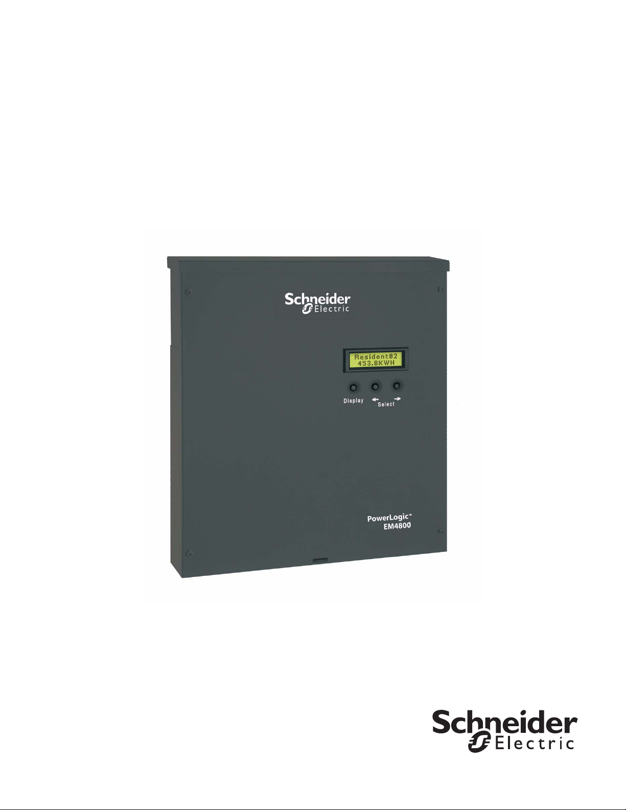
System Set-up and Description The configuration tool supports the PowerLogic EM4833, EM4880 and
EM4805 meters.
Depending on how the meters are installed and configured, they can meter
8, 12, or 24 individual meter points. The PowerLogic EM4833, EM4880 and
EM4805 meters are designed for residential, commercial, and industrial use
and display the power and consumption readings for each measurement
point.
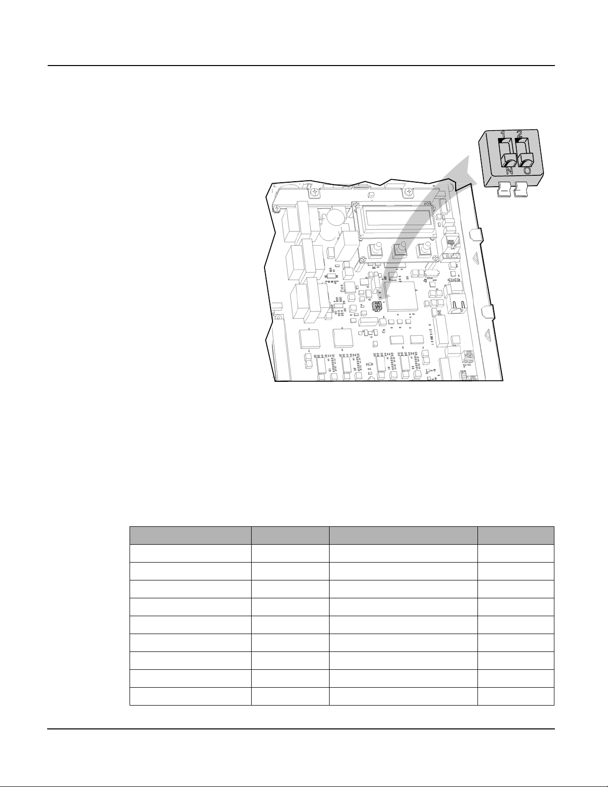
Configuration and Programming The configuration tool is used to set any of the programmable parameters of
the PowerLogic EM4800 Series meter. The combination of the configuration
tool and the state of the meter programming switches determine which
parameters can be set or changed. As shown in Figure 1, the programming
switches are two-position DIP switches labeled SW1, and are located inside
the meter cover below the Display button. To enable meter configuration,
both switches must be physically set to the ON (down) position (default).
© 2011 Schneider Electric All Rights Reserved
1
Page 8
PowerLogic
"SW1"
PowerLogic configuration tool 01/2011
TM
EM4800 Series 930-112-01-B.00
Figure 1: Programming Switch location
Table 1 lists the programming capabilities associated with each parameter in
combination with the programming switches. After the meter has been
programmed, the programming switches can be turned OFF to prevent
tampering with metering parameters.
Parameter Read access Write access Activation time
Meter name Configuration tool Configuration tool Immediate
Badge number Configuration tool Configuration tool Immediate
Phone number Configuration tool Configuration tool Immediate
Alternate phone number Configuration tool Configuration tool Immediate
AT string Configuration tool Configuration tool Immediate
Host upload directory Configuration tool Configuration tool Immediate
Host download directory Configuration tool Configuration tool Immediate
Host IP address Configuration tool Configuration tool Immediate
PPP user name Configuration tool Configuration tool Immediate
Table 1: Programming access to meter parameters
© 2011 Schneider Electric All Rights Reserved2
Page 9

930-112-01-B.00 PowerLogic
TM
EM4800 Series
01/2011 PowerLogic configuration tool
Parameter Read access Write access Activation time
PPP password Configuration tool Configuration tool Immediate
FTP user name Configuration tool Configuration tool Immediate
FTP password Configuration tool Configuration tool Immediate
Daily report interval start time Configuration tool Configuration tool Immediate
Daily report interval end time Configuration tool Configuration tool Immediate
Report period Configuration tool Configuration tool Immediate
Report interval in minutes Configuration tool Configuration tool Immediate
PT ratio Configuration tool Configuration tool + prog. switch ON Immediate
Default IP address Configuration tool Configuration tool Immediate
Default netmask Configuration tool Configuration tool Immediate
Default gateway Configuration tool Configuration tool Immediate
Reset dial readings No Access Configuration tool + prog. switch ON Immediate
Send PC time No Access Configuration tool Immediate
Programming switch state Configuration tool No Access Immediate
MAC address Configuration tool No Access Immediate
Report types Configuration tool Configuration tool Immediate
Manufacturing
Serial number Configuration tool No Access N/A
Part number Configuration tool No Access N/A
Model number Configuration tool Configuration tool + prog. switch ON After reset
Revision Configuration tool No Access
Firmware revision Configuration tool No Access N/A
Build number Configuration tool No Access
Meter and probe points
Name Configuration tool Configuration tool After reset
CT 1 current Configuration tool Configuration tool + prog. switch ON After reset
CT 2 current Configuration tool Configuration tool + prog. switch ON After reset
CT 3 current Configuration tool Configuration tool + prog. switch ON After reset
CT 1 phase Configuration tool Configuration tool + prog. switch ON After reset
CT 2 phase Configuration tool Configuration tool + prog. switch ON After reset
CT 3 phase Configuration tool Configuration tool + prog. switch ON After reset
© 2011 Schneider Electric All Rights Reserved
3
Page 10

PowerLogic
PowerLogic configuration tool 01/2011
TM
EM4800 Series 930-112-01-B.00
Display Navigation The display on the front of the meter provides status information for each
circuit, and general information for metering. The PowerLogic EM4800 meter
has three buttons for navigating: a Display button, and left and right arrow
buttons. The display has a normal and a diagnostics mode.
Normal Mode
In Normal mode, the Display button scrolls through the information for each
meter. The left and right arrow buttons select the previous or next meter
points respectively. The following information is available:
• Real Energy Delivered kWh D
• Real Energy Received kWh R
• Real Power Watts
• Reactive Energy Delivered KVarhD
• Reactive Energy Received KVarhR
• Reactive Power Var
In Normal mode, the right and left arrow buttons scroll the display from meter
points 1 to 8, 1 to 12, or 1 to 24, depending on your configuration.
Diagnostics Mode
Diagnostics mode is accessed by pressing and holding the Display button for
5 seconds. In Diagnostics mode, pressing the Display button will scroll
through the following additional information:
• Send data command
• CT Primary value and Real Power Watts per phase
• Voltage per phase
• Local IP address
• Reset factory default IP address command
• Date and time (UTC)
In Diagnostics mode, the right and left arrow buttons scroll the display from
meter 1 through N. When the local IP address is shown on the LCD, use the
right and left arrow buttons to scroll through the following information:
• Remote host server IP address
• Time server IP address
• Default IP address
• Default NetMask
• Default gateway
• PPP user name
• Phone number
• AT command string
• Alternate phone number
• Unit serial number
• Firmware build number
• Ethernet port MAC address
• Firmware revision
• Potential transformer ratio
© 2011 Schneider Electric All Rights Reserved4
Page 11

930-112-01-B.00 PowerLogic
DANGER
01/2011 PowerLogic configuration tool
TM
EM4800 Series
Communications Connections If you are configuring the meter at the installation site, see the PowerLogic
EM4800 Series Meter Installation Guide for instructions on connecting the
power. Power connections vary depending on whether the meter is
configured for single-phase or three-phase operation.
If you are pre-configuring the meter in the shop, only Phase A, Neutral, and
protective earth connections are required to power up the PowerLogic
EM4800 Series meter for configuring.
The PowerLogic EM4800 Series Configuration Tool communicates with the
PowerLogic meters through an Ethernet network connection. A network
connection can be accomplished in two ways: either Direct using an Ethernet
crossover cable, or by connecting to a LAN (Local Area Network).
NOTE: If you are attempting to use the list function, the PC being used
to configure the device MUST be on the same network segment as the
PowerLogic meters to be configured. The connect function will allow
the user to find the PowerLogic meters on or off the same segment,
however you must know the correct IP address of the unit being
modified.
Direct Connection Ethernet Requirements
HAZARD OF ELECTRIC SHOCK, EXPLOSION, OR ARC FLASH
• Apply appropriate personal protective equipment (PPE) and follow
safe electrical work practices. See NFPA 70E.
• This equipment must only be installed and serviced by qualified
electrical personnel.
• Turn off all power supplying this equipment before working on or
inside equipment.
• Always use a properly rated voltage sensing device to confirm
power is off.
• Replace all devices, doors and covers before turning on power to
this equipment.
• The meters must be connected to the sense voltage and control
voltage through a properly rated disconnect.
Failure to follow these instructions will result in death or serious
injury.
© 2011 Schneider Electric All Rights Reserved
To connect a PC directly to the PowerLogic EM4800 Series meter:
1. Disconnect power from the meter with the installed breaker or
disconnecting device. Use a properly rated voltage sensing device to
confirm power is off.
2. Remove the outer cover.
3. If you are changing parameters that require the programming switch to
be on, remove the inner cover and ensure the programming switches
are in the ON position.
4. Re-install the inner cover.
5. Remove the local LAN Ethernet cable if present and connect the CAT 5
Ethernet cross-over cable between the PC and the PowerLogic
EM4800 Series meter.
6. Restore power to the meter.
5
Page 12

PowerLogic
DANGER
PowerLogic configuration tool 01/2011
TM
EM4800 Series 930-112-01-B.00
7. Assign the PC a static IP address such that the first three segments are
the same as the default IP address, and the last segment is different
from the default IP address. For example, 169.254.0.xxx, where xxx
differs from the last segment of the default IP address.
8. Configure the meter. See “Configuring the Meters” on page 7 for
configuration instructions.
9. Remove power. Use a properly rated voltage sensing device to confirm
power is off.
10. If you wish to lock the configuration parameters, remove the inner cover
and move the programming switches (SW1) to the OFF (up) position.
11. Re-install the inner cover.
12. Connect the LAN Etherent cable if present.
13. Re-install the outer cover.
14. Restore power.
NOTE: All PowerLogic EM4800 Series meters have a default IP
address of 169.254.0.10 in the absence of a DHCP service.
Network Connection Ethernet Requirements
HAZARD OF ELECTRIC SHOCK, EXPLOSION, OR ARC FLASH
• Apply appropriate personal protective equipment (PPE) and follow
safe electrical work practices. See NFPA 70E.
• This equipment must only be installed and serviced by qualified
electrical personnel.
• Turn off all power supplying this equipment before working on or
inside equipment.
• Always use a properly rated voltage sensing device to confirm
power is off.
• Replace all devices, doors and covers before turning on power to
this equipment.
• The meters must be connected to the sense voltage and control
voltage through a properly rated disconnect.
Failure to follow these instructions will result in death or serious
injury.
To connect the PowerLogic EM4800 Series meter to the network:
1. Turn off power to the meter with the installed breaker or disconnecting
device. Use a properly rated voltage sensing device to confirm power
is off.
2. Remove the outer cover.
3. If you are changing parameters that require the programming switch to
be on, remove the inner cover and ensure the programming switches
are in the ON position.
4. Re-install the inner cover.
5. Using a CAT 5 Ethernet patch cable, connect the meter to a local
Ethernet switch.
6. Re-install the outer cover.
© 2011 Schneider Electric All Rights Reserved6
Page 13

930-112-01-B.00 PowerLogic
01/2011 PowerLogic configuration tool
TM
EM4800 Series
7. Restore power. When control power is restored, the meter will receive
an IP address from a local DHCP server. This IP address can be
viewed from the Diagnostics menu.
NOTE: To use a static IP address, have your local network
administrator assign the desired IP address to the MAC address of the
meter in the DHCP server configuration. To display the MAC address,
see “Display Navigation” on page 4.
Configuring the Meters The PowerLogic EM4800 Series configuration tool is available on the CD
shipped with each unit, and is used to configure all programmable
parameters listed in Table 1.
Login Use the following procedure to log in to the meter.
1. Establish an Ethernet network connection with the meter using one of
the methods descirbed in “Communications Connections” on page 5.
2. Ensure the programming switches are in the ON position. The
programming switches are two-position DIP switches labeled SW1, and
are located inside the meter cover below the Display button. To enable
meter configuration, both switches must be physically set to the ON
position. When both switches are in the OFF position, meter
configuration is disabled.
3. Start the configuration tool by entering “PowerLogic” as the User
Name, and “E4800” as the Password (see Figure 2). Click Ok.
Figure 2: Login screen
4. The main window displays as shown in Figure 3.
© 2011 Schneider Electric All Rights Reserved
7
Page 14

PowerLogic
PowerLogic configuration tool 01/2011
TM
EM4800 Series 930-112-01-B.00
Figure 3: Configuration tool main window
Connecting to a Meter The configuration tool automatically detects and lists the PowerLogic meters
on the same network segment as the PC. The configuration tool can also be
used with meters on a different network.
To connect to a meter on the same network:
1. Click Unit in the menu ba r, then se lect List from the drop-down menu.
The Discovered Units window appears, displaying a list of meters
available for configuration. See Figure 4.
© 2011 Schneider Electric All Rights Reserved8
Page 15

930-112-01-B.00 PowerLogic
01/2011 PowerLogic configuration tool
TM
EM4800 Series
Figure 4: Discovered Units dialog box
2. Select the Load Unit Configuration check box, then click Ok. The
main configuration tool window appears populated with the current
programming information for the selected meter. See Figure 5.
3. Proceed to “Unit Field Configuration Tab” on page 10.
To connect to a meter on a different networ k:
1. Click Unit in the menu bar, then select Connect from the drop-down
menu. The Connect to Unit window appears. See Figure 5.
Figure 5: Connect function window
2. Enter the IP address of the meter to be configured, then click Connect.
The configuration tool main window appears populated with the current
programming information for the selected meter. See Figure 6.
3. Proceed to “Unit Field Configuration Tab” on page 10.
© 2011 Schneider Electric All Rights Reserved
9
Page 16

PowerLogic
PowerLogic configuration tool 01/2011
TM
EM4800 Series 930-112-01-B.00
Figure 6: Main configuration window with configured parameters
Unit Field Configuration Tab Use Table 2 to set meter configuration parameters in the Unit Field
Configuration tab.
© 2011 Schneider Electric All Rights Reserved10
Page 17

930-112-01-B.00 PowerLogic
TM
EM4800 Series
01/2011 PowerLogic configuration tool
Table 2: Unit Field Configuration tab parameters
Field Parameter Description
Unit Field Configuration Current IP Address The current IP address for the unit .This parameter is read only and cannot
Mac Address The current MAC address for the unit. This parameter is read only and
be changed by the user.
cannot be changed by the user.
Revision The revision number of the unit.
Default IP Configuration IP Address The default IP address. This parameter is configured when DHCP has
been disabled, or DHCP services are not available on the network.
Netmask The default subnet mask. This parameter is configured when DHCP has
Gateway The default gateway. This parameter is configured when DHCP has been
been disabled, or DHCP services are not available on the network.
disabled, or DHCP services are not available on the network.
DNS Primary The primary domain name server. This parameter is configured when
DHCP has been disabled, or DHCP services are not available on the
network.
DNS Secondary The secondary domain ame server. This parameter is configured when
DHCP has been disabled, or DHCP services are not available on the
network.
DHCP Enabled If DHCP is not enabled, the meter uses the Default IP Configuration
parameters. If DHCP is enabled, the meter uses the IP configuration
parameters provided by the network DHCP service.
Report See “Report Parameters” on
page 12
Main Meter PT Ratio The main meter potential transformer ratio. This is an internal multiplier
used by the meter for external potential transformers. External PTs can be
used with a PT ratio of 1 if the billing system will apply the PT muliplier.
Use a PT Ratio of 1 with no external PTs.
Modem Phone # The phone number of your internet service provider’s PPP service.
Alternate Phone # An alternate phone number of your internet service provider’s PPP service.
AT String AT command string to customize modem operation. Default string is ATX3,
Wait for Dial Tone Do not enable this parameter if the line has a broken dial tone due to a
do not wait for dial tone.
message waiting feature.
Host Server IP Address The IP address or domain name of the FTP server for data storage.
Upload Directory The sub-directory used for data reporting within the root directory. The root
directory is determined by the FTP user name and the FTP server
configuration. The FTP account must have write access to this directory.
Download Directory The sub-directory used by the meter to retrieve configuration updates. The
FTP account must have read access to this directory..
FTP Login User Name The user name for the FTP account.
Password The password for the FTP account.
PPP Login User Name The user name for the PPP account. This is only required if using dial-up
Password The password for the PPP account. This is only required if using dial-up
reporting.
reporting.
NTP Host (Time Server) IP Address The IP address of the NTP server that provides timing to the meter.
© 2011 Schneider Electric All Rights Reserved
11
Page 18

PowerLogic
PowerLogic configuration tool 01/2011
TM
EM4800 Series 930-112-01-B.00
Report Parameters
The Report section in the main configuration window has three tabs:
• the Period tab allows the user to configure when the reports are
generated and the interval at which data is collected. Figure 7 shows
the Period tab, and Table 3 lists the configuration parameters within the
tab.
• the Types tab allows the user to configure the types of reports that are
generated, and to define the metering parameters that are to be logged
on an interval basis. Figure 8 shows the Types tab, and Table 4 lists the
configuration parameters within the tab.
• the Real Time Interval tab allows the user to configure real time
reporting daily, or at a specified regular interval in minutes. It allows the
user to define how often the meter is to send interval data to a server.
This setting works independently from the Period tab setting. Figure 9
shows the Real Time Interval tab, and Table 5 lists the configuration
parameters within the tab.
• the Power Factor tab allows the user to configure the type of power
factor calculation and the display format for leading vs. lagging power
factor. Figure 10 shows the Power Factor tab, and Table 6 lists the
configuration parameters within the tab.
• the BACnet tab allows the user to configure the BACnet Device ID.
Figure 11 shows the BACnet tab, and Table 7 lists the configuration
parameters within the tab.
© 2011 Schneider Electric All Rights Reserved12
Page 19

930-112-01-B.00 PowerLogic
01/2011 PowerLogic configuration tool
TM
EM4800 Series
Figure 7: Period tab in the Report section
© 2011 Schneider Electric All Rights Reserved
Table 3: Period tab configuration parameters
Parameter Description
Interval in Minutes The interval at which data is collected.
13
Page 20

PowerLogic
TM
EM4800 Series 930-112-01-B.00
PowerLogic configuration tool 01/2011
Figure 8: Types tab in the Report section
Table 4: Types tab configuration parameters
Parameter Description
Watt Hours Delivered Interval/Register
Watt Hours Received Interval/Register
VAR Hours Delivered Interval/Register
VAR Hours Received Interval/Register
VA Hours Interval/Register
Voltage
Pulses
These types of records can be enabled
by selecting the check box.
© 2011 Schneider Electric All Rights Reserved14
Page 21

930-112-01-B.00 PowerLogic
01/2011 PowerLogic configuration tool
TM
EM4800 Series
Figure 9: Real Time Interval tab in the Report section
© 2011 Schneider Electric All Rights Reserved
Table 5: Real Time Interval tab configuration parameters
Parameter Description
Daily Enables daily real time reporting by
Start Time When daily reporting is enabled, you
End Time When daily reporting is enabled, you
Minutes Enables real time reporting every x
selecting the radial button. The unit
defaults to daily reporting and sends
the data file at a randomly selected
time within the report window.
can set the reporting period start time.
can set the reporting period end time.
number of minutes by selecting the
radial button and entering the interval
in miuntes.
15
Page 22

PowerLogic
TM
EM4800 Series 930-112-01-B.00
PowerLogic configuration tool 01/2011
Figure 10: Power Factor tab in the Report section
Table 6: Power Factor tab configuration parameters
Parameter Description
Format
IEEE
IEC
Method of Calculation
You can set the display format to IEC
or IEEE by selecting the radial button.
This sign indicates leading (+) or
lagging (-) power. The direction of
active power is not indicated.
The sign (+ or -) indicates the direction
of active power and provides an
additional indicator for capacitive or
inductive (leading or lagging) power.
You can set the power factor method of
calculation to Arithmetic or Vector by
selecting the radial button.
© 2011 Schneider Electric All Rights Reserved16
Page 23

930-112-01-B.00 PowerLogic
TM
EM4800 Series
01/2011 PowerLogic configuration tool
Figure 11: BACnet tab in the Report section
© 2011 Schneider Electric All Rights Reserved
Table 7: BACnet tab configuration parameters
Parameter Description
BACnet Device ID
You can set the BACnet device ID by
entering a 4-digit numeric ID.
17
Page 24

PowerLogic
PowerLogic configuration tool 01/2011
TM
EM4800 Series 930-112-01-B.00
Manufacturing Tab The Manufacturing tab allows the user to define the metering configuration
for the PowerLogic meters.The meters support the configurations listed in
Table 8.
Table 8: List of supported metering configurations
PowerLogic EM4805 PowerLogic EM4833 PowerLogic EM4880
EM480510-1P-12 EM483310-1P-12 EM488010-1P-12
EM480510-1P-24 EM483310-1P-24 EM488010-1P-24
EM480510-2P-12 EM483310-2P-12 EM488010-2P-12
EM480510-2P-24 EM483310-2P-24 EM488010-2P-24
EM480510-3P-08 EM483310-3P-08 EM488010-3P-08
To view the manufacturing information for a specific meter, select a model
number from the Model # pull-down list shown in Figure 12. The part
number, revision number and serial number for the selected model will be
shown.
Figure 12: Manufacturing tab
© 2011 Schneider Electric All Rights Reserved18
Page 25

930-112-01-B.00 PowerLogic
01/2011 PowerLogic configuration tool
TM
EM4800 Series
Meter Points (Circuits) Tab The Meter Points (Circuits) tab contains the configuration information for
each of the metering points. It shows the number of elements used, the
phase, the current ratings, and the user-defined identification string for each
meter point. Default information is entered when the metering configuration
is selected in the Manufacturing Tab (see “Manufacturing Tab” on page 18).
Meter Point Configuration
The current rating and phase assignment for each meter point can be
configured individually, by meter, or all at once. The configuration in all three
cases does not take effect until the new settings have been sent to the meter
(see “Completing the Meter Configuration” on page 23).
To change the current rating and phase assignment for an individual meter
point:
1. Select one probe at a time from the Meter Points (Circuits) List. The
selected probe number will appear in the middle pane beside Probe,
and its assigned Current and Phase are shown beneath it. See Figure
13.
2. To change the Current, enter the required number. To change the
Phase, select the required phase type from the pull-down list.
Figure 13: Meter Points configuration screen
© 2011 Schneider Electric All Rights Reserved
19
Page 26

PowerLogic
PowerLogic configuration tool 01/2011
TM
EM4800 Series 930-112-01-B.00
To change the current rating for all meter points assigned to a meter:
1. Select a meter from the Meter Points (Circuits) List. The selected
meter will appear in the Name field of the middle pane. See Figure 13.
2. In the Alter Current for Probes pane, enter the desired value
referenced to the CT primary rating in the Current field, and click on
Change Probes in Selected Meter.
To change the current rating for all meter points assigned to all meters:
1. In the Alter Current for Probes pane, enter the desired value
referenced to the CT primary rating in the Current field, and click on
Change all Probes in all Meters. See Figure 13.
Badge Numbering
Each meter point can be configured with a name defined by the user. The
meter point name, known as the badge number, can be up to 13
alphanumeric characters in length. The Badge Numbering pane allows the
user to set two types of badge numbers:
• sequential, which assigns a badge number to each meter point after the
prefix (for example CORP-00000001 to CORP-00000012)
• grouped by meter, which uses a base prefix to designate the meter,
then assigns a sequential badge number suffix to each meter point
assigned to that meter (for example CORP-00001-01 to
CORP-00001-12)
The configuration tool provides examples before the badge number is
assigned to the meter. In the Badge Numbering pane shown in Figure 14,
the following fields and buttons are provided for assigning badge numbers:
• Prefix field - an alphanumeric field that prefixes the number field.
• Badge Number field - a numeric field that becomes part of the prefix
for meter points assigned to that meter, or the first number in the
sequence to be assigned to individual meter points.
• Badge Number Width field - a numeric field that defines the number of
digits in the badge number field. Zeroes (0) are automatically entered
at the beginning of the badge number field until the total number of
digits in the badge number field equals the number of digits defined in
the badge number width field.
• Incremental badge numbers button - selecting this button assigns a
sequential badge number for each meter point
• Single badge number button - selecting this button assigns one badge
number prefix followed by a numeric suffix for each meter point
assigned to that meter.
• Assign Badge Numbers button - selecting this button implements the
badge numbering defined by the user in the previous fields.
• Reset Dial Readings button - selecting this button resets all registers
for all energy types and pulse counts to zero. This function takes effect
immediately and does not require a send action.
• Send PC Time button - selecting this button configures the meter with
the current PC time and UTC. This function takes effect immediately
and does not require a send action. This function can be used when
access to the network time service is not available.
© 2011 Schneider Electric All Rights Reserved20
Page 27

930-112-01-B.00 PowerLogic
TM
EM4800 Series
01/2011 PowerLogic configuration tool
Figure 14: Badge Numbering pane
© 2011 Schneider Electric All Rights Reserved
21
Page 28

PowerLogic
PowerLogic configuration tool 01/2011
TM
EM4800 Series 930-112-01-B.00
Pulse Probes Tab The Pulse Probes tab contains the configuration information for each pulse
input. It shows the measurement type in units for each input, and the scale
factor applied to the collected pulse counts. Figure 15 shows the Pulse
Probes tab of the main configuration tool window.
To configure a pulse probe:
1. Select a pulse probe from the Probe List.
2. Select a measurement type from the Type pull-down list.
3. Enter a value in the Scale Factor field.
NOTE: The scale factor only changes the pulse values in the TR3
report.
Figure 15: Pulse Probes tab
© 2011 Schneider Electric All Rights Reserved22
Page 29

930-112-01-B.00 PowerLogic
01/2011 PowerLogic configuration tool
TM
EM4800 Series
Completing the Meter Configuration Once you have defined all of the configurable parameters, the PowerLogic
EM4800 Series meter is ready to be programmed.
To complete the meter configuration:
1. Click Unit in the menu bar, then select Save from the drop-down menu.
See Figure 16.
Figure 16: Saving the configuration settings
© 2011 Schneider Electric All Rights Reserved
23
Page 30

PowerLogic
PowerLogic configuration tool 01/2011
TM
EM4800 Series 930-112-01-B.00
2. Click Unit in the menu bar, then select Send from the drop-down menu
to transmit the configuration settings from your PC to the selected
PowerLogic EM4800 Series meter. The confirmation message File
loaded successfully! should appear in the bottom left corner of the
window. See Figure 17.
Figure 17: Sending the configured settings to the meter
© 2011 Schneider Electric All Rights Reserved24
Page 31

930-112-01-B.00 PowerLogic
TM
EM4800 Series
01/2011
© 2011 Schneider Electric All Rights Reserved
Page 32

PowerLogic
TM
EM4800 Series
Configuration Guide
Schneider Electric USA
Power Monitoring and Control
295 Tech Park Drive, Suite 100
Lavergne, TN 37086 USA
1-888-SquareD
(1-888-778-2733)
www.us.SquareD.com
Electrical equipment should be installed, operated, serviced, and maintained only by qualified
personnel. No responsibility is assumed by Schneider Electric for any consequences ari sing out of
the use of this material.
930-112-01-B.00 © 2011 Schneider Electric All Rights Reserved
01/2011
 Loading...