

Page 1
PowerLogic
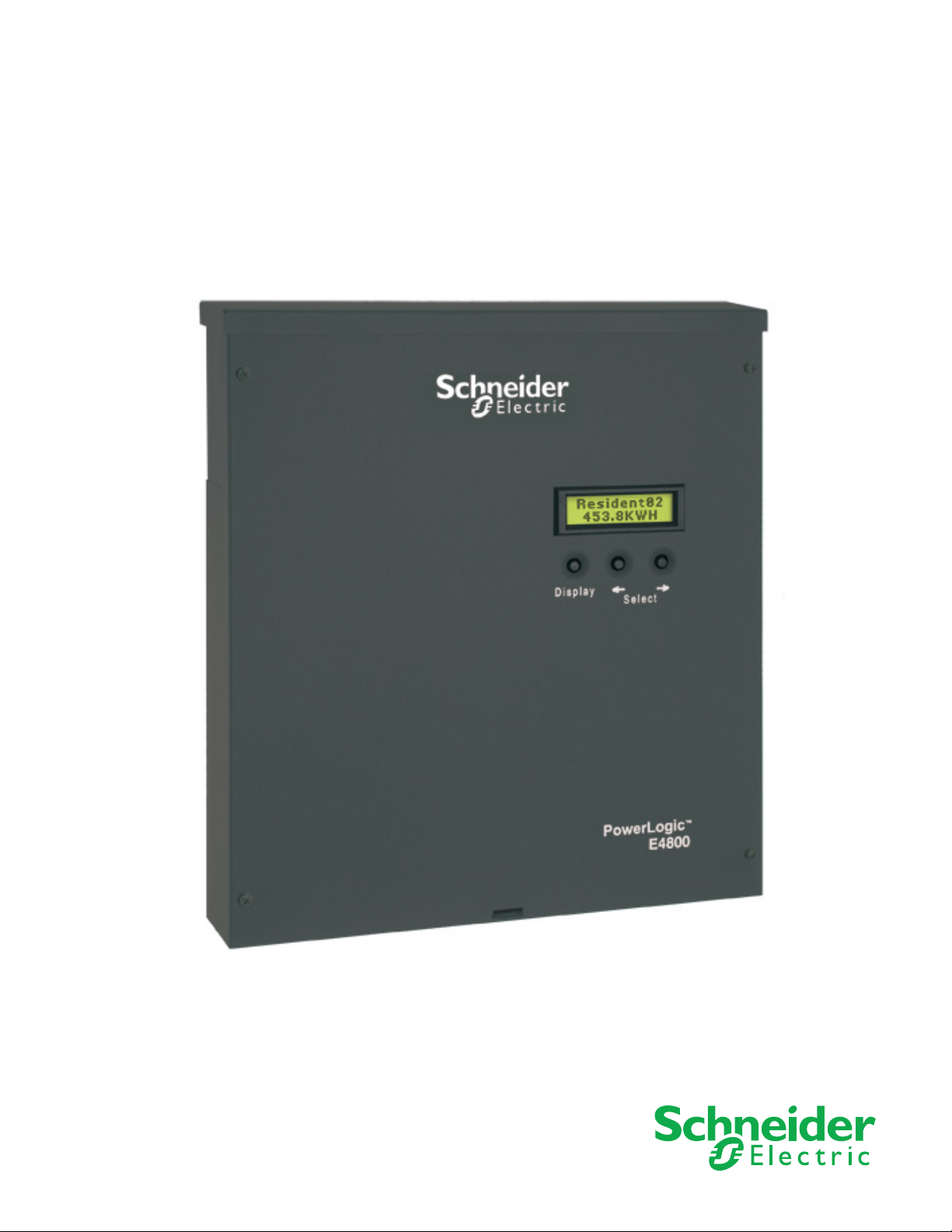
Multi-Circuit Meters
930-112-01-D.00
11/2013
TM
Series EM4000/EM4800
Page 2

Page 3
Safety Information
Important Information
Read these instructions carefully and look at the equipment to become
familiar with the device before trying to install, operate, service or maintain it.
The following special messages may appear throughout this manual or on
the equipment to warn of potential hazards or to call attention to information
that clarifies or simplifies a procedure.
The addition of either symbol to a “Danger” or “Warning” safety label indicates that
an electrical hazard exists which will result in personal injury if the instructions are
not followed.
This is the safety alert symbol. It is used to alert you to potential personal injury
hazards. Obey all safety messages that follow this symbol to avoid possible injury
or death.
DANGER indicates an imminently hazardous situation which, if not avoided, will
result in death or serious injury.
Please note
WARNING indicates a potentially hazardous situation which, if not avoided, can
result in death or serious injury.
CAUTION indicates a potentially hazardous situation which, if not avoided, can
result in minor or moderate injury.
NOTICE is used to address practices not related to physical injury. The safety
alert symbol shall not be used with this signal word.
Electrical equipment should be installed, operated, serviced and maintained only by
qualified personnel. No responsibility is assumed by Schneider Electric for any
consequences arising out of the use of this material.
A qualified person is one who has skills and knowledge related to the construction,
installation, and operation of electrical equipment and has received safety training
to recognize and avoid the hazards involved.
Page 4

Notices
FCC Part 15 Notice
This equipment has been tested and found to comply with the limits for a Class B
digital device, pursuant to part 15 of the FCC Rules. These limits are designed to
provide reasonable protection against harmful interference in a residential
installation. This equipment generates, uses, and can radiate radio frequency
energy and, if not installed and used in accordance with the instructions, may
cause harmful interference to radio communications. However, there is no
guarantee that interference will not occur in a particular installation. If this
equipment does cause harmful interference to radio or television reception, which
can be determined by turning the equipment off and on, the user is encouraged to
try to correct the interference by one or more of the following measures.
• Reorient or relocate the receiving antenna.
• Increase the separation between the equipment and receiver.
• Connect the equipment to an outlet on a circuit different from that to which the
receiver is connected.
• Consult the dealer or an experienced radio/TV technician for help.
This Class B digital apparatus complies with Canadian ICES-003.
FCC Part 68 Notice
This equipment complies with Part 68 of the FCC rules and the requirements
adopted by the Administrative Council for Terminal Attachments (ACTA). On the
side of this equipment is a label that contains, among other information, a product
identifier in the format US: AAAEQ##TXXXX. If requested, this number must be
provided to the telephone company.
This equipment uses the following Universal Service Order Codes (“USOC”) jacks:
RJ11.
A plug and jack used to connect this equipment to the premises wiring and
telephone network must comply with the applicable FCC Part 68 rules and
requirements adopted by the ACTA. A compliant telephone cord and modular plug
or compliant modular jack is provided with this product.
The REN is used to determine the number of devices that may be connected to a
telephone line. Excessive RENs on a telephone line may result in the devices not
ringing in response to an incoming call. In most but not all areas, the sum of RENs
should not exceed five (5.0). To be certain of the number of devices that may be
connected to a line, as determined by the total RENs, contact the local telephone
company. The REN for this product is part of the product identifier that has the
format US: AAAEQ##TXXXX. The digits represented by ## are the REN without a
decimal point (e.g., 03 is a REN of 0.3).
If this equipment, Digital Power Meter with Internal Modem, causes harm to the
telephone network, the telephone company will notify you in advance that service
may be temporarily discontinued. When advance notice is not practical, the
Page 5

telephone company will notify you as soon as possible. You will also be advised of
your right to file a complaint with the FCC if you believe it is necessary.
The telephone company may make changes in its facilities, equipment, operations
or procedures that could affect the operation of this equipment. If this happens, the
telephone company will provide advance notice in order for you to make necessary
modifications to maintain uninterrupted service.
If you experience trouble with this equipment, Digital Power Meter with Internal
Modem, please contact Schneider Electric at 615-287-3400. If this equipment is
causing harm to the telephone network, the telephone company may request that
you disconnect this equipment until the problem is resolved.
There are no user serviceable parts in this equipment.
Connection to party line service is subject to state tariffs. Contact the state public
utility commission, public service commission or corporation commission for
information.
If your premises has specially wired alarm equipment connected to the telephone
line, ensure that the installation of this Digital Power Meter with Internal Modem
does not disable your alarm equipment. If you have questions about what will
disable alarm equipment, consult your telephone company or a qualified installer.
Network Compatibility Notice for the Internal Modem
The internal modem in meters equipped with this option is compatible with the
telephone systems of most countries in the world, with the exception of Australia
and New Zealand. Use in some countries may require modification of the internal
modem’s initialization strings. If problems using the modem on your phone system
occur, please contact Schneider Electric Technical Support.
Page 6

Page 7

930-112-01-D.00 PowerLogic
11/2013 Table of Contents
TM
EM4000/EM4800 Series
Table of Contents
PowerLogic configuration tool ..................................................................... 1
System Set-up and Description ............................................................. 1
Configuration and Programming...................................................... 1
Display Navigation........................................................................... 3
Communications Connections ......................................................... 5
Configuring the Meters .......................................................................... 7
Login................................................................................................ 7
Connecting to a Meter ..................................................................... 8
Unit Field Configuration Tab.......................................................... 10
Manufacturing Tab......................................................................... 19
Meter Points (Circuits) Tab............................................................ 21
Pulse Probes Tab .......................................................................... 24
Completing the Meter Configuration .............................................. 26
User notes ................................................................................................. 29
©2013 Schneider Electric All Rights Reserved
i
Page 8

PowerLogic
TM
EM4000/EM4800 Series 930-112-01-D.00
Table of Contents 11/2013
©2013 Schneider Electric All Rights Reservedii
Page 9

930-112-01-D.00 PowerLogicTM Series EM4000/EM4800
11/2013
PowerLogic configuration tool
This document describes how to configure the PowerLogic EM4000/EM4800
Series meters, using the PowerLogic configuration tool. It includes the following
configuration tool information:
• “System Set-up and Description” on page 1
• “Configuration and Programming” on page 1
• “Display Navigation” on page 3
• “Communications Connections” on page 5
• “Configuring the Meters” on page 7
• “Login” on page 7
• “Connecting to a Meter” on page 8
• “Unit Field Configuration Tab” on page 10
• “Manufacturing Tab” on page 19
• “Meter Points (Circuits) Tab” on page 21
• “Pulse Probes Tab” on page 24
• “Completing the Meter Configuration” on page 26
This documentation is intended for those responsible for configuring the
PowerLogic meters.
System Set-up and Description
The configuration tool supports the following PowerLogic meters
• PowerLogic EM4000 Series: PowerLogic EM4033 and EM4080 meters
• PowerLogic EM4800 Series: PowerLogic EM4805, EM4833, and EM4880
meters
Depending on how the meters are installed and configured, they can meter 8, 12, or
24 individual meter points. The PowerLogic meters are designed for residential,
commercial, and industrial use and display the power and consumption readings
for each measurement point.
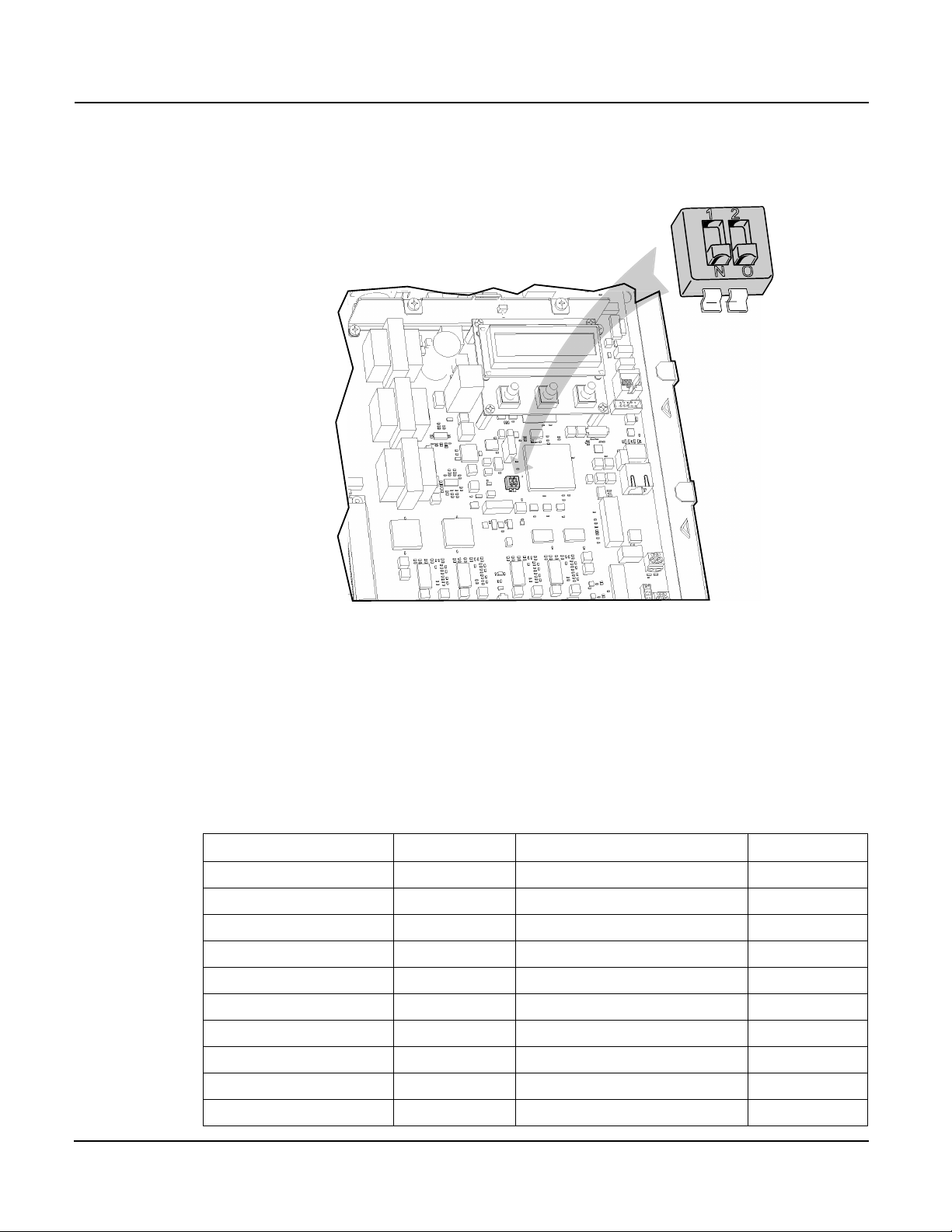
Configuration and Programming
The configuration tool is used to set any of the programmable parameters of the
PowerLogic EM4000/EM4800 Series meter. The combination of the configuration
tool and the state of the meter programming switches determine which parameters
can be set or changed. As shown in Figure 1, the programming switches are
two-position DIP switches labeled SW1, and are located inside the meter cover
below the Display button. To enable meter configuration, both switches must be
physically set to the ON (down) position (default).
©2013 Schneider Electric All Rights Reserved 1
Page 10
PowerLogicTM Series EM4000/EM4800 930-112-01-D.00
"SW1"
11/2013
Figure 1: Programming Switch location
Table 1 lists the programming capabilities associated with each parameter in
combination with the programming switches. After the meter has been
programmed, the programming switches can be turned OFF to prevent tampering
with metering parameters.
Table 1: Programming access to meter parameters
Parameter Read access Write access Activation time
Meter name Configuration tool Configuration tool Immediate
Badge number Configuration tool Configuration tool Immediate
Phone number Configuration tool Configuration tool Immediate
Alternate phone number Configuration tool Configuration tool Immediate
AT string Configuration tool Configuration tool Immediate
Host upload directory Configuration tool Configuration tool Immediate
Host download directory Configuration tool Configuration tool Immediate
Host IP address Configuration tool Configuration tool Immediate
PPP user name Configuration tool Configuration tool Immediate
PPP password Configuration tool Configuration tool Immediate
2 ©2013 Schneider Electric All Rights Reserved
Page 11

930-112-01-D.00 PowerLogicTM Series EM4000/EM4800
11/2013
Parameter Read access Write access Activation time
FTP user name Configuration tool Configuration tool Immediate
FTP password Configuration tool Configuration tool Immediate
Daily report interval start time Configuration tool Configuration tool Immediate
Daily report interval end time Configuration tool Configuration tool Immediate
Report period Configuration tool Configuration tool Immediate
Report interval in minutes Configuration tool Configuration tool Immediate
PT ratio Configuration tool Configuration tool + prog. switch ON Immediate
Default IP address Configuration tool Configuration tool Immediate
Default netmask Configuration tool Configuration tool Immediate
Default gateway Configuration tool Configuration tool Immediate
Reset dial readings No Access Configuration tool + prog. switch ON Immediate
Send PC time No Access Configuration tool Immediate
Programming switch state Configuration tool No Access Immediate
MAC address Configuration tool No Access Immediate
Report types Configuration tool Configuration tool Immediate
Manufacturing
Serial number Configuration tool No Access N/A
Part number Configuration tool No Access N/A
Model number Configuration tool Configuration tool + prog. switch ON After reset
Revision Configuration tool No Access
Firmware revision Configuration tool No Access N/A
Build number Configuration tool No Access
Meter and probe points
Name Configuration tool Configuration tool After reset
CT 1 current Configuration tool Configuration tool + prog. switch ON After reset
CT 2 current Configuration tool Configuration tool + prog. switch ON After reset
CT 3 current Configuration tool Configuration tool + prog. switch ON After reset
CT 1 phase Configuration tool Configuration tool + prog. switch ON After reset
CT 2 phase Configuration tool Configuration tool + prog. switch ON After reset
CT 3 phase Configuration tool Configuration tool + prog. switch ON After reset
Display Navigation
The display on the front of the meter provides status information for each circuit,
and general information for metering. The PowerLogic meter has three buttons for
navigating: a Display button, and left and right arrow buttons. The display has
a normal and a diagnostics mode.
©2013 Schneider Electric All Rights Reserved 3
Page 12

PowerLogicTM Series EM4000/EM4800 930-112-01-D.00
11/2013
Normal Mode
In Normal mode, the Display button scrolls through the information for each meter.
The left and right arrow buttons select the previous or next meter points
respectively. The following information is available:
• Real Energy Delivered kWh D
• Real Energy Received kWh R
• Real Power Watts
• Reactive Energy Delivered kVarhD
• Reactive Energy Received kVarhR
• Reactive Power Var
• Peak Demand PeakW (Watts)
In Normal mode, the right and left arrow buttons scroll the display from meter points
1 to 8, 1 to 12, or 1 to 24, depending on your configuration.
Diagnostics Mode
Diagnostics mode is accessed by pressing and holding the Display button for 5
seconds. In Diagnostics mode, pressing the Display button will scroll through the
following information in addition to the Normal mode data:
• Send data command
• CT Primary value and Real Power (Watts) per phase
• Current (Amps) per phase
• Power Factor (pf) per phase
• Phase angle (Degrees) per phase
• Voltage per phase
• Local IP address
• Reset factory default IP address command
•Verify
• Badge #
• Date and time (UTC)
In Diagnostics mode, the right and left arrow buttons scroll the display from meter 1
through N. When the local IP address is shown on the LCD, use the right and left
arrow buttons to scroll through the following information:
• Remote host server IP address
• Time server IP address
• Default IP address
• Default NetMask
• Default gateway
• PPP user name
• Phone number
• AT command string
• Alternate phone number
• Unit serial number
• Firmware build number
4 ©2013 Schneider Electric All Rights Reserved
Page 13

930-112-01-D.00 PowerLogicTM Series EM4000/EM4800
11/2013
• Ethernet port MAC address
• Firmware revision
• Potential transformer ratio
Communications Connections
If you are configuring the meter at an installation site, see the PowerLogic EM4000
Series Meter Installation Guide or the PowerLogic EM4800 Series Meter
Installation Guide for instructions on connecting the power. Power connections vary
depending on whether the meter is configured for single-phase or three-phase
operation.
If you are pre-configuring the meter in the shop, only Phase A, Neutral, and
protective earth connections are required to power up the meter for configuring.
The PowerLogic EM4000/EM4800 Series Configuration Tool runs on a Windows
PC and communicates with the PowerLogic meters through an Ethernet network
connection. A network connection can be accomplished in two ways: either Direct,
or by connecting to a LAN (Local Area Network).
Direct Connection Ethernet Requirements
HAZARD OF ELECTRIC SHOCK, EXPLOSION, OR ARC FLASH
• Apply appropriate personal protective equipment (PPE) and follow
safe electrical work practices. See NFPA 70E.
• This equipment must only be installed and serviced by qualified
electrical personnel.
• Turn off all power supplying this equipment before working on or
inside equipment.
• Always use a properly rated voltage sensing device to confirm
power is off.
• Replace all devices, doors and covers before turning on power to
this equipment.
• The meters must be connected to the sense voltage and control
voltage through a properly rated disconnect.
Failure to follow these instructions will result in death or serious
injury.
To connect a PC directly to the PowerLogic meter:
1. Disconnect power from the meter with the installed breaker or disconnecting
device. Use a properly rated voltage sensing device to confirm power is off.
2. Remove the outer cover.
3. If you are changing parameters that require the programming switch to be on,
remove the inner cover and ensure the programming switches are in the ON
position.
4. Re-install the inner cover.
5. Remove the local LAN Ethernet cable if present and connect the CAT 5
Ethernet cable between the PC and the PowerLogic meter. If the PC does not
have auto-crossover detection, an Ethernet crossover cable will be required.
6. Restore power to the meter.
©2013 Schneider Electric All Rights Reserved 5
Page 14

PowerLogicTM Series EM4000/EM4800 930-112-01-D.00
11/2013
7. Assign the PC a static IP address such that the first three segments are the
same as the default IP address, and the last segment is different from the
default IP address.
For example, 169.254.0.xxx, where xxx differs from the last segment of the
default IP address.
Enter 255.255.255.0 into the subnet mask field.
For Windows 7 users, you must enter the IP address of the meter into the
Default Gateway field.
8. Configure the meter. See “Configuring the Meters” on page 7 for configuration
instructions.
9. Remove power. Use a properly rated voltage sensing device to confirm power is
off.
10.If you wish to lock the configuration parameters, remove the inner cover and
move the programming switches (SW1) to the OFF (up) position.
11.Re-install the inner cover.
12.Connect the LAN Ethernet cable if present.
13.Re-install the outer cover.
14.Restore power.
NOTE: All PowerLogic meters have a default IP address of 169.254.0.10 in the
absence of a DHCP service.
Network Connection Ethernet Requirements
HAZARD OF ELECTRIC SHOCK, EXPLOSION, OR ARC FLASH
• Apply appropriate personal protective equipment (PPE) and follow
safe electrical work practices. See NFPA 70E.
• This equipment must only be installed and serviced by qualified
electrical personnel.
• Turn off all power supplying this equipment before working on or
inside equipment.
• Always use a properly rated voltage sensing device to confirm
power is off.
• Replace all devices, doors and covers before turning on power to
this equipment.
• The meters must be connected to the sense voltage and control
voltage through a properly rated disconnect.
Failure to follow these instructions will result in death or serious
injury.
To connect the PowerLogic meter to the network:
1. Turn off power to the meter with the installed breaker or disconnecting device.
Use a properly rated voltage sensing device to confirm power is off.
2. Remove the outer cover.
3. If you are changing parameters that require the programming switch to be on,
remove the inner cover and ensure the programming switches are in the ON
position.
6 ©2013 Schneider Electric All Rights Reserved
Page 15

930-112-01-D.00 PowerLogicTM Series EM4000/EM4800
11/2013
4. Re-install the inner cover.
5. Using a CAT 5 Ethernet patch cable, connect the meter and the PC to a local
Ethernet switch.
6. Re-install the outer cover.
7. Restore power. When control power is restored, the meter will receive an IP
address from a local DHCP server. This IP address can be viewed from the
Diagnostics menu.
NOTE: To use a static IP address, have your local network administrator assign
the desired IP address to the MAC address of the meter in the DHCP server
configuration. To display the MAC address, see “Display Navigation” on page 3.
Configuring the Meters
The PowerLogic EM4000/EM4800 Series configuration tool is available on the CD
shipped with each unit, and is used to configure all programmable parameters
listed in Table 1.
NOTE: Disable any firewall software on your PC before attempting to connect to
a meter using the configuration tool.
Login
Use the following procedure to log in to the meter.
1. Establish an Ethernet network connection with the meter using one of the
methods described in “Communications Connections” on page 5.
2. Ensure the programming switches are in the ON position. The programming
switches are two-position DIP switches labeled SW1, and are located inside the
meter cover below the Display button. To enable meter configuration, both
switches must be physically set to the ON position. When both switches are in
the OFF position, meter configuration is disabled.
3. Start the configuration tool by entering “PowerLogic” as the User Name, and
“E4800” as the Password (see Figure 2). Click Ok.
Figure 2: Login screen
4. The main window displays as shown in Figure 3.
©2013 Schneider Electric All Rights Reserved 7
Page 16

PowerLogicTM Series EM4000/EM4800 930-112-01-D.00
11/2013
Figure 3: Configuration tool main window
Connecting to a Meter
The configuration tool automatically detects and lists the PowerLogic meters on the
same network segment as the PC. The configuration tool can also be used with
meters on a different network.
8 ©2013 Schneider Electric All Rights Reserved
Page 17

930-112-01-D.00 PowerLogicTM Series EM4000/EM4800
11/2013
To connect to a meter on the same network:
1. Click Unit in the menu bar, then select List from the drop-down menu. The
Discovered Units window appears, displaying a list of meters available for
configuration. See Figure 4.
Figure 4: Discovered Units dialog box
2. Select the Load Unit Configuration check box, then click Ok. The main
configuration tool window appears populated with the current programming
information for the selected meter. See Figure 5.
3. Proceed to “Unit Field Configuration Tab” on page 10.
To connect to a meter on a different network:
1. Click Unit in the menu bar, then select Connect from the drop-down menu. The
Connect to Unit window appears. See Figure 5.
Figure 5: Connect function window
©2013 Schneider Electric All Rights Reserved 9
Page 18

PowerLogicTM Series EM4000/EM4800 930-112-01-D.00
11/2013
2. Enter the IP address of the meter to be configured, then click Connect. The
configuration tool main window appears populated with the current
programming information for the selected meter. See Figure 6.
3. Proceed to “Unit Field Configuration Tab” on page 10.
Figure 6: Main configuration window with configured parameters
Unit Field Configuration Tab
Use Table 2 to set meter configuration parameters in the Unit Field Configuration
tab.
10 ©2013 Schneider Electric All Rights Reserved
Page 19

930-112-01-D.00 PowerLogicTM Series EM4000/EM4800
11/2013
Table 2: Unit Field Configuration tab parameters
Field Parameter Description
Unit Field Configuration Current IP Address The current IP address for the unit .This parameter is read only and cannot be
Mac Address The current MAC address for the unit. This parameter is read only and cannot be
Revision The revision number of the unit.
Default IP Configuration IP Address The default IP address. This parameter is configured when DHCP has been disabled,
Netmask The default subnet mask. This parameter is configured when DHCP has been
Gateway The default gateway. This parameter is configured when DHCP has been disabled, or
DNS Primary The primary domain name server. This parameter is configured when DHCP has been
DNS Secondary The secondary domain name server. This parameter is configured when DHCP has
DHCP Enabled If DHCP is not enabled, the meter uses the Default IP Configuration parameters. If
Report See “Report Parameters” on page 12
Main Meter PT Ratio The main meter potential transformer ratio. This is an internal multiplier used by the
Modem Phone # The phone number of your internet service provider’s PPP service.
Alternate Phone # An alternate phone number of your internet service provider’s PPP service.
changed by the user.
changed by the user.
or DHCP services are not available on the network.
disabled, or DHCP services are not available on the network.
DHCP services are not available on the network.
disabled, or DHCP services are not available on the network.
been disabled, or DHCP services are not available on the network.
DHCP is enabled, the meter uses the IP configuration parameters provided by the
network DHCP service.
meter for external potential transformers. External PTs can be used with a PT ratio of
1 if the billing system will apply the PT multiplier.
Use a PT Ratio of 1 with no external PTs.
AT String AT command string to customize modem operation. Default string is ATX3, do not wait
Wait for Dial Tone Do not enable this parameter if the line has a broken dial tone due to a message
Host Server IP Address The IP address or domain name of the FTP server for data storage.
Upload Directory The sub-directory used for data reporting within the root directory. The root directory
Download Directory The sub-directory used by the meter to retrieve configuration updates. The FTP
FTP Login User Name The user name for the FTP account.
Password The password for the FTP account.
PPP Login User Name The user name for the PPP account. This is only required if using dial-up reporting.
Password The password for the PPP account. This is only required if using dial-up reporting.
NTP Host (Time Server) IP Address The IP address of the NTP server that provides timing to the meter.
for dial tone.
waiting feature.
is determined by the FTP user name and the FTP server configuration. The FTP
account must have write access to this directory.
account must have read access to this directory..
©2013 Schneider Electric All Rights Reserved 11
Page 20

PowerLogicTM Series EM4000/EM4800 930-112-01-D.00
11/2013
Report Parameters
The Report section in the main configuration window has six tabs:
• Intervals tab allows the user to configure the recording interval at which meter data is
collected, and the demand interval for which demand readings are calculated. Figure 7
shows the Intervals tab, and Table 3 lists the configuration parameters within the tab.
• Types tab allows the user to define the metering data parameters that are to be logged
on each recording interval, then reported per the Reporting Schedule. Figure 8 shows
the Types tab, and Table 4 lists the configuration parameters within the tab.
• Reporting Schedule tab allows the user to configure how often the meter is to send
recording interval data to a server. Figure 9 shows the Reporting Schedule tab, and
Table 5 lists the configuration parameters within the tab.
• Calculations & Format tab allows the user to configure the type of power factor
calculation and the display format for leading vs. lagging power factor. Figure 10 shows
the Calculations & Format tab, and Table 6 lists the configuration parameters within the
tab.
• BACnet tab allows the user to configure the BACnet Device interface. Figure 11 shows
the BACnet tab, and Table 7 lists the configuration parameters within the tab.
• Comms tab allows the user to configure the communications module and change the
Meter Utility Password. Figure 12 shows the Comms tab, and Table 8 lists the
configuration parameters within the tab.
Figure 7: Intervals tab in the Report section
Table 3: Intervals tab configuration parameters
Parameter Description
Recording Interval in Minutes The interval at which meter data is collected.
Demand Interval Setup
Block Demand Select Block Demand calculation for demand data.
Sliding Window Demand Select Sliding Window Demand calculation for demand data.
12 ©2013 Schneider Electric All Rights Reserved
Page 21

930-112-01-D.00 PowerLogicTM Series EM4000/EM4800
11/2013
Parameter Description
Demand Interval in Minutes The size of the block demand window in minutes (select from the
Number of Sub-intervals The number of recording sub-intervals that make up the sliding
pull-down menu).
demand interval (select from the pull-down menu).
Example: Selecting a Recording Interval of 5 minutes with Sliding Window
Demand enabled and 3 Sub-intervals, creates a demand calculation every
5 minutes based on the previous 15 minutes. This is the common demand
measurement used by North American utilities when billing for Demand.
NOTE: To activate the Demand Interval Setup settings, Peak Demand must be
enabled (
) in the Types tab (see Figure 8).
Figure 8: Types tab in the Report section
©2013 Schneider Electric All Rights Reserved 13
Page 22

PowerLogicTM Series EM4000/EM4800 930-112-01-D.00
11/2013
Table 4: Types tab configuration parameters
Parameter Description
Watt Hours Delivered Interval/Register These types of records can be enabled by
Watt Hours Received Interval/Register
VAR Hours Delivered Interval/Register
VAR Hours Received Interval/Register
VA Hours Interval/Register
Present Demand
Peak Demand
Peak Current
Voltage
Pulses
selecting () the check box.
NOTE: If parameters are grayed out, they are not available on the variant or
firmware revision of the meter being configured.
14 ©2013 Schneider Electric All Rights Reserved
Page 23

930-112-01-D.00 PowerLogicTM Series EM4000/EM4800
11/2013
Figure 9: Reporting Schedule tab in the Report section
Table 5: Reporting Schedule tab configuration parameters
Parameter Description
Daily (default) Enables daily real time reporting.
Start Time When daily reporting is enabled, select the reporting period start time.
End Time When daily reporting is enabled, select the reporting period end time.
Minutes Enables real time reporting every x number of minutes by selecting the
The unit sends the data file at a randomly selected time within the
report window specified by the start and end time .
radial button and entering the interval in minutes.
NOTE: When selecting a Daily report schedule, the Start Time must occur
before the End Time within the midnight to midnight 24-hour time period.
©2013 Schneider Electric All Rights Reserved 15
Page 24

PowerLogicTM Series EM4000/EM4800 930-112-01-D.00
11/2013
Figure 10: Calculations & Format tab in the Report section
Table 6: Calculations & Format tab configuration parameters
Parameter Description
Power Factor
Sign Format IEEE In the display, the sign (+ or -) indicates leading (+) or
IEC (default) In the display, the sign (+ or -) indicates the direction
Method of Calculation Arithmetic Selects the arithmetic method for calculating Power
Vector (default) Selects the vector method for calculating Power
lagging (-) power. The direction of active power is not
indicated.
of active power. Lead or lag indicates capacitive or
inductive power.
Factor.
Factor
16 ©2013 Schneider Electric All Rights Reserved
Page 25

930-112-01-D.00 PowerLogicTM Series EM4000/EM4800
11/2013
Figure 11: BACnet tab in the Report section
Table 7: BACnet tab configuration parameters
Parameter Description
Device ID Set the BACnet device ID by entering a a numeric ID between 0 and
Network Port The BACnet specific port number for this device (default is 47808).
BBMD Timeout Enter the amount of time (seconds) required for connection to a BACnet
BBMD Address Enter the address of the BBMD device that controls all devices in the
Description A user selectable description of the device (default is Power Meter)
Vendor ID BACnet Vendor Identification number (default is 10)
Vendor Name Schneider Electric (default)
Software Version The software version of the PowerLogic product (fixed).
UTC Offset Fixed at 0
Location A user selectable description of the physical location of the unit (default is
Object Name PowerHawk Meter (default)
4194303.
network.
BACnet network.
Unknown).
©2013 Schneider Electric All Rights Reserved 17
Page 26

PowerLogicTM Series EM4000/EM4800 930-112-01-D.00
11/2013
Figure 12: Comms tab in the Report section
18 ©2013 Schneider Electric All Rights Reserved
Page 27

930-112-01-D.00 PowerLogicTM Series EM4000/EM4800
11/2013
Table 8: Comms tab configuration parameters
Parameter Description
Parameters
Comms Option Modem Selecting Modem configures the communications
None Selecting None disables the communications
RTU Adapter Selecting RTU Adapter configures the
RTU comms config Enter the RTU serial port parameters as a string
Modbus base address Enter the Modbus RTU address for this device (1
Utility Password
Current Password The default meter Utility Password is listed here
Enter new password To change the password, enter the new password.
Enter new password again To confirm, re-enter the new password.
module as a dial-up modem for remote reporting
via a phone line.
module interface
communications module as a Modbus
RS422/RS485 serial interface.
with the following selections: baud rate (19200 or
9600), number of bits (8), number of start bits (1),
number of stop bits (1), parity type (e – even, n –
none
Example: 19200,8,1,e (default)
to 255)
whenever the Configuration Tool is started or
when a configuration is uploaded from a meter.
If the Utility Password for the meter is not the
default password, enter the Current Password
here to change metering specific parameters or to
change the password again.
NOTE: The Modbus and RTU Adapter Comms Option parameters are valid only
when a Modem module or an RTU adapter module is present.
The RTU Adapter parameters apply only to Modbus RTU communications.
There are no configuration options when Modbus over TCP/IP is used.
NOTE: : The meter Utility Password is used to control access to changing the
metering specific parameters in the PowerLogic meter. The following
parameters and functions cannot be changed or activated unless the correct
Utility Password is entered before sending the new config to the meter:
PT Ratio
CT Current and Phase
Reset Dial Readings
Model Number
Change Password
All other parameters and functions can be changed or accessed without
entering the correct Utility Password for the meter being configured.
Manufacturing Tab
The Manufacturing tab allows the user to define the metering configuration for the
PowerLogic meters. The meters support the configurations listed in Table 9.
©2013 Schneider Electric All Rights Reserved 19
Page 28

PowerLogicTM Series EM4000/EM4800 930-112-01-D.00
11/2013
Table 9: List of supported PowerLogic metering configurations
EM4033xx EM4080xx EM4805xx EM4833xx EM4880xx
EM4033xx-1P-12 EM4080xx-1P-12 EM4805xx-1P-12 EM4833xx-1P-12 EM4880xx-1P-12
EM4033xx-1P-24 EM4080xx-1P-24 EM4805xx-1P-24 EM4833xx-1P-24 EM4880xx-1P-24
EM4033xx-2P-12 EM4080xx-2P-12 EM4805xx-2P-12 EM4833xx-2P-12 EM4880xx-2P-12
EM4033xx-2P-24 EM4080xx-2P-24 EM4805xx-2P-24 EM4833xx-2P-24 EM4880xx-2P-24
EM4033xx-3P-08 EM4080xx-3P-08 EM4805xx-3P-08 EM4833xx-3P-08 EM4880xx-3P-08
To view the manufacturing information for a specific meter, select a model number
from the Model # pull-down list shown in Figure 13. The part number, revision
number and serial number for the selected model will be shown.
Figure 13: Manufacturing tab
20 ©2013 Schneider Electric All Rights Reserved
Page 29

930-112-01-D.00 PowerLogicTM Series EM4000/EM4800
11/2013
Meter Points (Circuits) Tab
The Meter Points (Circuits) tab contains the configuration information for each of
the metering points. It shows the number of elements used, the phase, the current
ratings, and the user-defined identification string for each meter point. Default
information is entered when the metering configuration is selected in the
Manufacturing Tab (see “Manufacturing Tab” on page 19).
Meter Point Configuration
The current rating and phase assignment for each meter point can be configured
individually, by meter, or all at once. The configuration in all three cases does not
take effect until the new settings have been sent to the meter (see “Completing the
Meter Configuration” on page 26).
To change the current rating and phase assignment for an individual meter point:
1. Select one probe at a time from the Meter Points (Circuits) List. The selected
probe number will appear in the middle pane beside Probe, and its assigned
Current and Phase are shown beneath it. See Figure 14.
2. To change the Current, enter the required number. To change the Phase,
select the required phase type from the pull-down list.
Figure 14: Meter Points configuration screen
©2013 Schneider Electric All Rights Reserved 21
Page 30

PowerLogicTM Series EM4000/EM4800 930-112-01-D.00
11/2013
To change the current rating for all probes assigned to a meter point:
1. Select a meter from the Meter Points (Circuits) List. The selected meter will
appear in the Name field of the middle pane. See Figure 14.
2. In the Alter Current for Probes pane, enter the desired value referenced to the
CT primary rating in the Current field, and click on Change Probes in Selected
Meter.
To change the current rating for all probes assigned to all meter points:
1. In the Alter Current for Probes pane, enter the desired value referenced to the
CT primary rating in the Current field, and click on Change all Probes in all
Meters. See Figure 14.
Badge Numbering
Each meter point can be configured with a name defined by the user. The meter
point name, known as the badge number, can be up to 13 alphanumeric characters
in length. The Badge Numbering pane allows the user to set two types of badge
numbers:
• sequential, which assigns a badge number to each meter point after the prefix
(for example CORP-00000001 to CORP-00000012)
• grouped by meter, which uses a base prefix to designate the meter, then
assigns a sequential badge number suffix to each meter point assigned to that
meter (for example CORP-00001-01 to CORP-00001-12)
The configuration tool provides examples before the badge number is assigned to
the meter. In the Badge Numbering pane shown in Figure 15, the following fields
and buttons are provided for assigning badge numbers:
• Prefix field - an alphanumeric field that prefixes the number field.
• Badge Number field - a numeric field that becomes part of the prefix for meter
points assigned to that meter, or the first number in the sequence to be
assigned to individual meter points.
• Badge Number Width field - a numeric field that defines the number of digits in
the badge number field. Zeroes (0) are automatically entered at the beginning of
the badge number field until the total number of digits in the badge number field
equals the number of digits defined in the badge number width field.
• Incremental badge numbers button - selecting this button assigns a sequential
badge number for each meter point
• Single badge number button - selecting this button assigns one badge number
prefix followed by a numeric suffix for each meter point assigned to that meter.
• Assign Badge Numbers button - selecting this button implements the badge
numbering defined by the user in the previous fields.
22 ©2013 Schneider Electric All Rights Reserved
Page 31

930-112-01-D.00 PowerLogicTM Series EM4000/EM4800
11/2013
Figure 15: Badge Numbering pane
Reset Buttons
• Reset Dial Readings button - selecting this button resets all registers for all
energy types and pulse counts to zero. This function takes effect immediately
and does not require a send action.
• Send PC Time button - selecting this button configures the meter with the
current PC UTC and local time. This function takes effect immediately and does
not require a send action. This function can be used when access to the network
time service is not available.
©2013 Schneider Electric All Rights Reserved 23
Page 32

PowerLogicTM Series EM4000/EM4800 930-112-01-D.00
11/2013
• Adjust Dial Reading button - selecting this button allows the operator to set all
of the following energy type registers to the same fixed initial value:
• Delivered Watt Hours
• Received Watt Hours
• Delivered VAR Hours
• Received VAR Hours
• VA Hours
This function takes effect immediately and does not require a send action.
• Reset Demand Reading button - selecting this button resets the Peak Demand
register for all meter points to zero. This function takes effect immediately and
does not require a send action.
Pulse Probes Tab
The Pulse Probes tab contains the configuration information for each pulse input.
It shows the measurement type in units for each input, and the scale factor applied
to the collected pulse counts. Figure 16 shows the Pulse Probes tab of the main
configuration tool window.
To configure a pulse probe:
1. Enable () Pulses in the Types tab of the Report section in the Unit Field
Configuration tab. See Figure 8 on page 13.
NOTE: The Pulse Probe settings are not active unless Pulses are enabled in
the Types tab.
2. Select a pulse probe from the Probe List.
3. Select a measurement type from the Type pull-down list.
4. Enter a value in the Scale Factor field.
NOTE: This scale factor only changes the pulse values in the TR3 report. The
pulse count in the device web page is not scaled.
24 ©2013 Schneider Electric All Rights Reserved
Page 33

930-112-01-D.00 PowerLogicTM Series EM4000/EM4800
11/2013
Figure 16: Pulse Probes tab
©2013 Schneider Electric All Rights Reserved 25
Page 34

PowerLogicTM Series EM4000/EM4800 930-112-01-D.00
11/2013
Completing the Meter Configuration
Once you have defined all of the configurable parameters, the PowerLogic meter is
ready to be programmed.
To complete the meter configuration:
1. Click Unit in the menu bar, then select Save from the drop-down menu. See
Figure 17.
Figure 17: Saving the configuration settings
26 ©2013 Schneider Electric All Rights Reserved
Page 35

930-112-01-D.00 PowerLogicTM Series EM4000/EM4800
11/2013
2. Click Unit in the menu bar, then select Send from the drop-down menu to
transmit the configuration settings from your PC to the selected PowerLogic
meter. The confirmation message File loaded successfully! should appear in
the bottom left corner of the window. See Figure 18.
Figure 18: Sending the configured settings to the meter
©2013 Schneider Electric All Rights Reserved 27
Page 36

PowerLogicTM Series EM4000/EM4800 930-112-01-D.00
11/2013
28 ©2013 Schneider Electric All Rights Reserved
Page 37

930-112-01-D.00 PowerLogicTM Series EM4000/EM4800
11/2013
User notes
©2013 Schneider Electric All Rights Reserved 29
Page 38

PowerLogicTM Series EM4000/EM4800 930-112-01-D.00
11/2013
30 ©2013 Schneider Electric All Rights Reserved
Page 39

Page 40

PowerLogicTM Series EM4000/EM4800
Multi-Circuit Meters
Schneider Electric
35 rue Joseph Monier
92500 Rueil-Malmaison, France
www.schneider-electric.com
PowerLogic is a trademark or registered trademark of Schneider Electric in France, the USA and
other countries. Other trademarks used are the property of their respective owners.
This product must be installed, connected and used in compliance with prevailing standards
and/or installation regulations. As standards, specifications and designs change from time to time,
always ask for confirmation of the information given in this publication.
930-112-01-D.00 11/2013
©2013 All Rights Reserved
 Loading...