

Page 1
Application
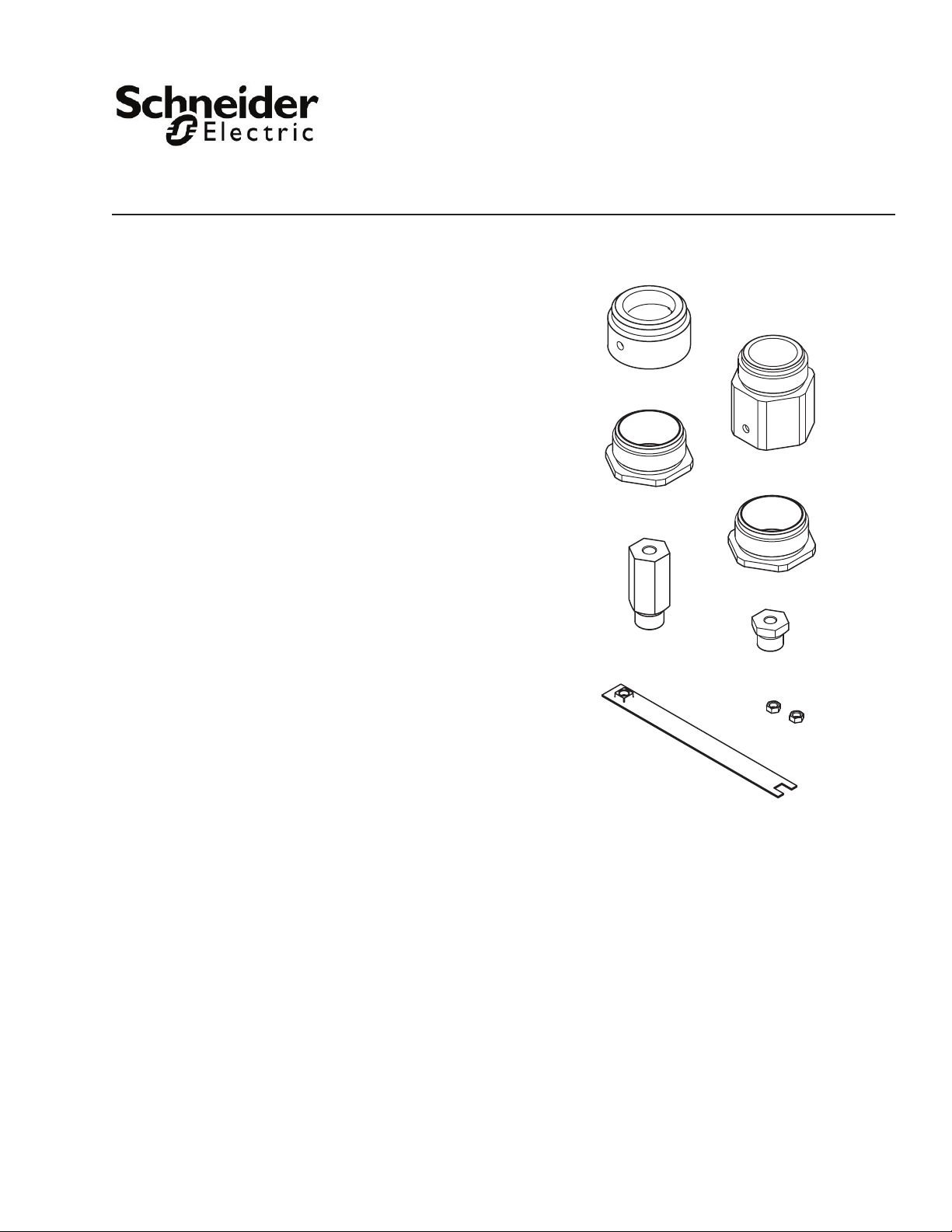
NYBA-182
ACME-258
ACME-220
NYBA-197-10
NYBA-197-20
YBA-519-1
TOOL-20-1
The AV-608 linkage adapter kit is designed to t the
Schneider Electric AV-607-1 linkage kit or the M400A,
M800A and M1500A Forta actuators to the
discontinued 1-1/2” and 2” VB-9XXX valves.
Features
• Compatible with Schneider Electric VB-9XXX 1-1/2”
and 2” valves and SmartX or M400A, M800A and
M1500A Forta actuators
• Kit contains necessary parts for either application
AV-608
Adapter for AV-607-1
Schneider Electric SmartX Linkage,
M400A, M800A and M1500A Forta Actuators, and
VB-9XXX 1-1/2” and 2” Valves
General Instructions
Schneider Electric
F-27234-5 October 2 014
Page 2

Applicable Literature
F-Number Description Audience Purpose
F-27599
F-26642
F-26644
F-26645
F-26742
F-26748
F-26749
F-27215
F-27082
F-26646
F-26752
F-11366 Valve Selection Chart Steam (two-way valves only)
F-11080 Valve Selection Chart Water
F-13755 CA-28 Control Valve Sizing
F-27234 AV-811 Forta to Globe valve adapter kit
F-26080 EN-205 Water System Guidelines
M400A (VB), M800A (VB) and M1500A (VB) Forta
Actuator General Instructions
MA40-704X, MA4X-707X, MA4X-715X Schneider
Electric Spring Return Two-Position SmartX Actuators
General Instructions
MF4X-7XX3 Schneider Electric Spring Return Floating
SmartX Actuator General Instructions
MS4X-7XX3 Schneider Electric Spring Return
Proportional SmartX Actuator General Instructions
MA40-717X Spring Return Direct Coupled SmartX
Actuator General Instructions
MS40-717X Schneider Spring Return Direct Coupled
SmartX Actuator General Instructions
MF40-7173 Schneider Electric Spring Return Direct
Coupled SmartX Actuator General Instructions
MF41-6153/MS41-6153 Series Non-spring return Rotary
Electronic Damper Actuators General Instructions
AV-607-1, AV-609-1 Schneider Electric SmartX Linkages
for 1-1/2” to 6” Globe Valves General Instructions
MX4X-7XXX, MX4X-6XXX Series Schneider Electric
SmartX Actuator Selection Guide
VX-7000 and VX-9000 Series Linked Globe Valve
Assemblies and MX4X-7XXX and MX4X-6XXX Series
Actuator/Linkage Assemblies with Schneider Electric
SmartX Actuators, Selection Guide
– Sales Personnel
– Application Engineers
– Installers
– Service Personnel
– Start-up Technicians
– Application Engineers
– Installers
– Service Personnel
– Start-up Technicians
Describes the actuator’s features,
specications, and possible applications.
Provides step-by-step mounting
instructions and wiring instructions for the
actuator/linkage assemblies.
Describes the linkages’ specications and
possible applications. Provides step-bystep mounting instructions for the actuator/
linkage assemblies.
Provides actuator specications and part
number cross referencing of phased out
actuators with the new Schneider Electric
direct-coupled actuators.
Provides features, specications,
mounting dimensions, and other criteria
useful to the selection of linked globe valve
assemblies and actuator/linkage
assemblies with Schneider Electric
SmartX actuators.
Provides charts, equations, and diagrams
to assist in the conguration of valve
system applications. TOOL-150, valve
sizing slide rule may be purchased
separately
Provides information on how to install the
adapter on globe valves up to 2”.
Describes Schneider Electric’
recommended water treatment practices.
2
Schneider Electric
F-27234-5 October 2 014
Page 3
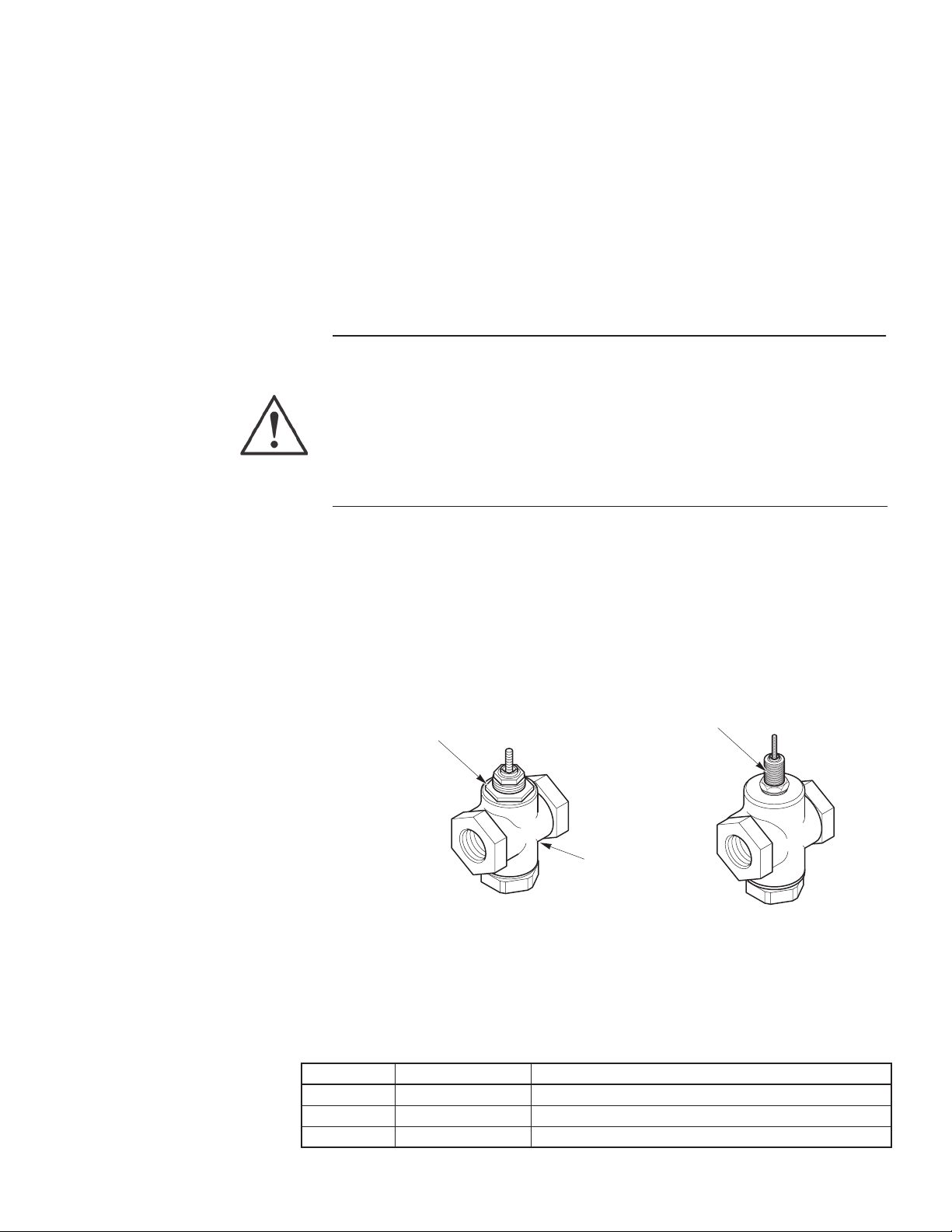
Style A VB-9XXX
1-1/2" and 2"
(40 and 50 mm)
valve body
Style B VB-9XXX
1-1/2" and 2"
(40 to 50 mm)
valve body
Valve Mounting Nut
Globe style
body
1-3/8" high, 1" diameter
threaded bonnet
INSTALLATION
3
Inspection
Requirements
General Installation
Inspect package for damage. If damaged, notify carrier immediately. If undamaged, open
the package and inspect for obvious damage. Return damaged products.
• Training: Installer must be a qualied, experienced technician.
• Tools (not provided):
– Measuring scale graduated in 1/16””increments
– Two 5/16” open-end wrenches or TOOL-20-1 for jam nuts
– 3/4 to 2” spanner wrench for linkage adapter
– 1-3/8” open-end wrench for valve adapter
– 1-5/8” open-end wrench for valve mounting nut
– Vise grip or pliers
– Appropriate power supply (see the applicable actuator General Instructions sheet
for power requirements)
Warning: Electrical shock hazard! Contact with live circuits can result in severe injury or
death.
• Disconnect the power supply (line power) at the breaker or fuse before and during
installation of an actuator to prevent electric shock and equipment damage.
• Make all connections in accordance with the wiring diagram and in accordance with
national and local electrical codes. Use copper conductors only.
Failure to observe these warnings can result in severe injury or death and can damage the
equipment.
The AV-608 kit contains parts for the AV-607 linkage and Schneider Electric jackscrew style
actuators. Save the unused parts and instructions for other applications.
Allow at least 5” (127 mm) above the actuator or actuator/linkage assembly for removal and
reattachment to the installed valve.
Valve Styles
Identify the valve body and follow the specic instructions on the following pages.
• Style A valve bodies were discontinued in August, 1997
• Some style B valve bodies were discontinued in 1994 (date code 9404)
Figure-1 Valve Body Identication.
Table-1 Model Chart – Valve Bodies
Model Type Description
VB-921X 2-Way stem up open Seat on bottom, closed when stem down
VB-922X 2-Way stem up closed Seat on top, closed when stem up
VB-931X 3-Way mixing Seat on top and bottom, one inlet closed when stem up or down
Schneider Electric
F-27234-5 October 2 014
Page 4

Mounting AV-607-1
Linkage to Valve Body
1 Install two YBA-519-1 jam
nuts on the valve stem,
3/16" from the top of the
valve stem and lock
together using TOOL-20-1
or 5/16" open-end
wrenches. The second
nut enables you to hold or
rotate the valve stem if
necessary.
AV-607-1 Linkage
To attach the linkage to the valve body, refer to the subsection that applies to the specic
valve body.
AV-607-1 Linkage and Style A Valve Bodies
1. Remove any previously installed actuator and linkage parts.
2. Assemble the linkage to the valve, according to Figure-2.
Note: If necessary for ease of assembly, remove the actuator from the linkage.
2 Raise the valve
stem to the full
up position.
3 Install the NYBA-197-10
Adapter into the rack end
and tighten with a 5/8"
open-end wrench.
4
5 Rotate the linkage, fully
engaging the stem until
the NYBA-197-10
contacts the jam nuts.
6 Lock the nuts securely
against the adapter using
TOOL-20-1 or 5/16"
open-end wrenches.
7 While holding the valve
mounting nut, rotate the
entire linkage, threading
the mounting nut onto the
NYBA-182 Adapter.
4 Install the NYBA-182
Adapter into the bottom of
the rack housing and
tighten with a 3/4 to 2"
spanner wrench.
8 Orient the linkage on the
valve as desired and then
using TOOL-37 or an
1-5/8" open-end wrench,
lock the assembly into
place.
9 Rotate the pinion shaft with pliers
in both directions, confirming the
seats are reached for close off. If
necessary, remove the linkage
cover with a Torx screwdriver and
observe the rack. The valve seats
should control the stroke, not the
linkage cover or rack teeth.
If stem up closed valves do not
seat, increase the stroke by
returning to Step 1 and lowering
the two jam nuts on the stem as
needed.
Figure-2 Assembling the AV-607-1 Linkage Onto a Style A Valve Body.
Schneider Electric
F-27234-5 October 2 014
Page 5

1 Install two YBA-519-1 jam
nuts on the valve stem,
3/16" from the top of the
valve stem and lock
together using TOOL-20-1
or 5/16" open-end
wrenches. The second
nut enables you to hold or
rotate the valve stem if
necessary.
2 Install one ACME-220
Adaptor with the hexagon
down onto the valve
bonnet as far as possible.
For stem up closed
valves, back the valve
adapter up three full
turns.
3 Raise the valve
stem to the full
up position.
4 Install the NYBA-197-20
Adapter into the rack end
and tighten with a 5/8"
open-end wrench.
5 Install the NYBA-182
Adapter into the bottom of
the rack housing.
6 Install one ACME-220
Adapter into the
NYBA-182 in the rack
housing and tighten with
an 1-3/8" open-end
wrench.
7 Rotate the linkage, fully
engaging the stem until
the NYBA-197-20
contacts the jam nuts.
If the valve stem rotates,
use a 5/16" open-end
wrench to turn the stem
into the adapter.
8 Lock the nuts securely
against the adapter using
TOOL-20-1 or 5/16"
open-end wrenches.
9 Rotate the entire linkage,
threading it onto the valve
bonnet, fully engaging the
bottom ACME-220
Adapter.
10 Orient the linkage on the
valve as desired and then
using an 1-3/8" open-end
wrench, lock the
assembly into place with
the bottom ACME-220
11 Rotate the pinion shaft with pliers
in both directions, confirming the
seats are reached for close off. If
necessary, remove the linkage
cover with a Torx screwdriver and
observe the rack. The valve seats
should control the stroke, not the
linkage cover or rack teeth.
If stem up closed valves do not
seat, increase the stroke by
backing the assembly up and
then back the bottom ACME-220
Adapter up additional turns as
shown in Step 2.
AV-607-1 Linkage and Style B Valve Bodies
5
1. Remove any previously installed actuator and linkage parts.
2. Assemble the linkage to the valve, according to Figure-3.
Note: If necessary for ease of assembly, remove the actuator from the linkage.
Schneider Electric
F-27234-5 October 2 014
Figure-3 Assembling the AV-607-1 Linkage Onto a Style B Valve Body.
Page 6

Mounting M400A,
M800A and M1500A
Forta Actuators to
Valve Body
Install one YBA-519-1 jam nut
1
to the bottom of stem thread.
M400A , M800A and M1500A Forta Style Actuators
To mount the actuator to the valve body, refer to the subsection that applies to the specic
valve body.
M400A, M800A and M1500A Forta and Style A Valve Bodies
1. Remove any previously installed actuator and linkage parts.
2. Assemble the new linkage to the valve, according to Figure-4.
Then install stem extension, from AV-811
2
kit, to bottom of thread on stem and
lock together using TOOL-20 or 5/16
open-end wrench.
Tighten
6
Install theAV-811 assembly (make sure
3
the mounting adapter bottoms out on
top of the valve bonnet) tighten the valve
actuator nut to the mounting adapter.
Tighten
4
Push valve stem to full down position
Mount Forta actuator to stem extension slot
5
and bolt the U-clamp to the mounting adapter.
Manual override may be required to align
U-clamp assembly. See AV-811 documentation
for further mounting detail.
Figure-4 Assembling the Forta Actuator Onto a Style A Valve Body.
Schneider Electric
F-27234-5 October 2 014
Page 7

M400A, M800A and M1500A Forta Actuators and Style B Valve Bodies
Mount Forta actuator to stem extension slot
and bolt the U-clamp to the mounting adapter.
U-clamp assembly. See AV-811 documentation
Tighten the ACME-220 to the mounting adapter.
1. Remove any previously installed actuator and linkage parts.
2. Assemble the new linkage to the valve, according to Figure-5.
Install one YBA-519-1 jam nut
1
to the bottom of stem thread.
Install one ACME-220 adapter with
3
hexagon down onto the valve bonnet
as far as possible without tightening.
Then install stem extension, from AV-811
2
kit, to bottom of thread on stem and
lock together using TOOL-20 or 5/16
open-end wrench.
Tighten
7
Install the AV-811 mounting adapter to the
4
ACME-220. Make sure the mounting adapter
bottoms out on the top of the valve bonnet.
Tighten
Push valve stem to full down position
5
6
Manual override may be required to align
for further mounting detail.
Figure-5 Assembling the Forta Actuator onto a Style B Valve Body.
Schneider Electric
F-27234-5 October 2 014
Page 8

Schneider Electric
F-27234-5 October 2 014
© 2014 Schneider Electric. All rights reserved.
 Loading...