

Page 1
Application
The A V-601 linkage extension is required for all heating
valves with MF-5X13, MP-541X, MP-551X,
MPR-561X, MPR-571X, and MPR-581X actuators. It is
recommended for cooling valves with MF-5X13,
MP-541X, MP-551X, MPR-561X, MPR-571X, and
MPR-581X actuators. It is also used for higher ambient
and fluid temperatures with MA-521X or MP-521X
actuators.
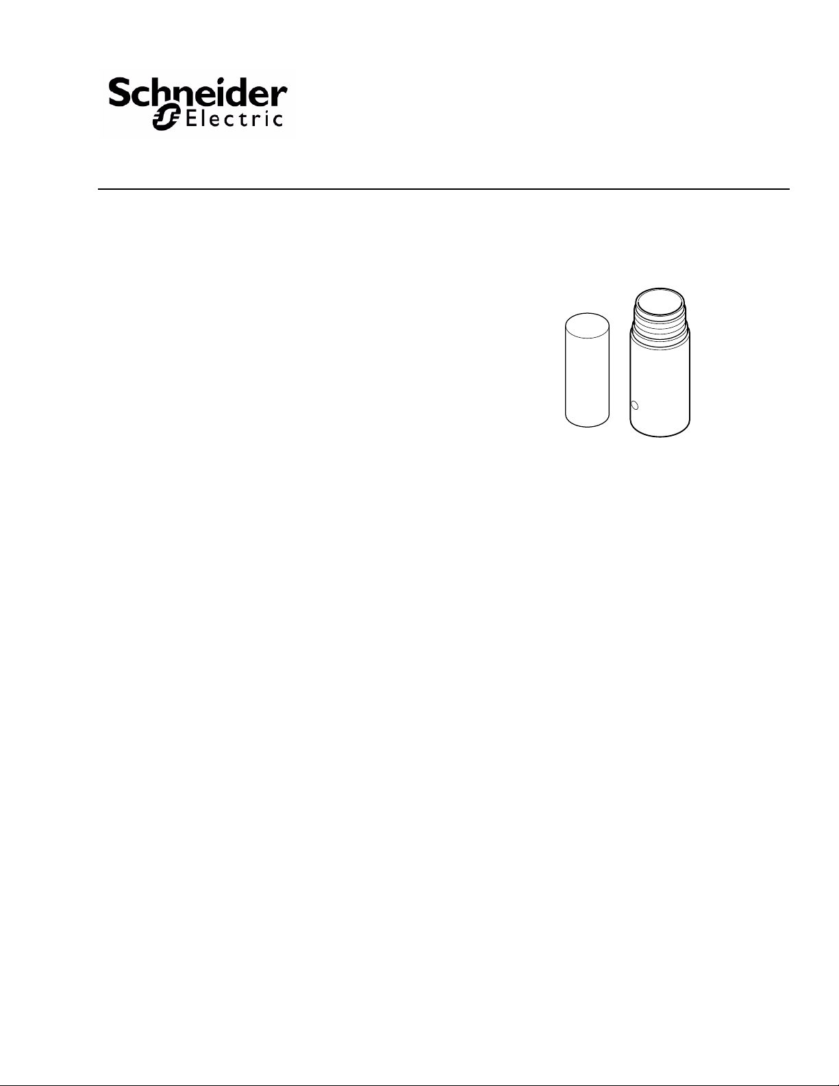
AV-601
Linkage Extension Kit
General Instructions
Features
• AV-601 provides thermal insulation between valve
and actuator.
Applicable Literature
• Environmental Controls Cross-Reference Guide, F-
23638
• Environmental Controls Reference Manual,
F-12683
• Environmental Controls Application Manual,
F-21335
• Pneumatic Products Catalog, F-27383
• Environmental Controls Valve Selection Guide, F-
26094
• EN-205 Water System Guidelines, F-26080
• AV-600 Hydraulic Actuator Valve Linkage Kit
General Instructions, F-26279
• AV-7600 Hydraulic Actuator Valve Linkage Kit,
F-26235
Printed in U.S.A. 4/10 © Copyright 2010 Schneider Electric All Rights Reserved. F-26280-3
Page 2
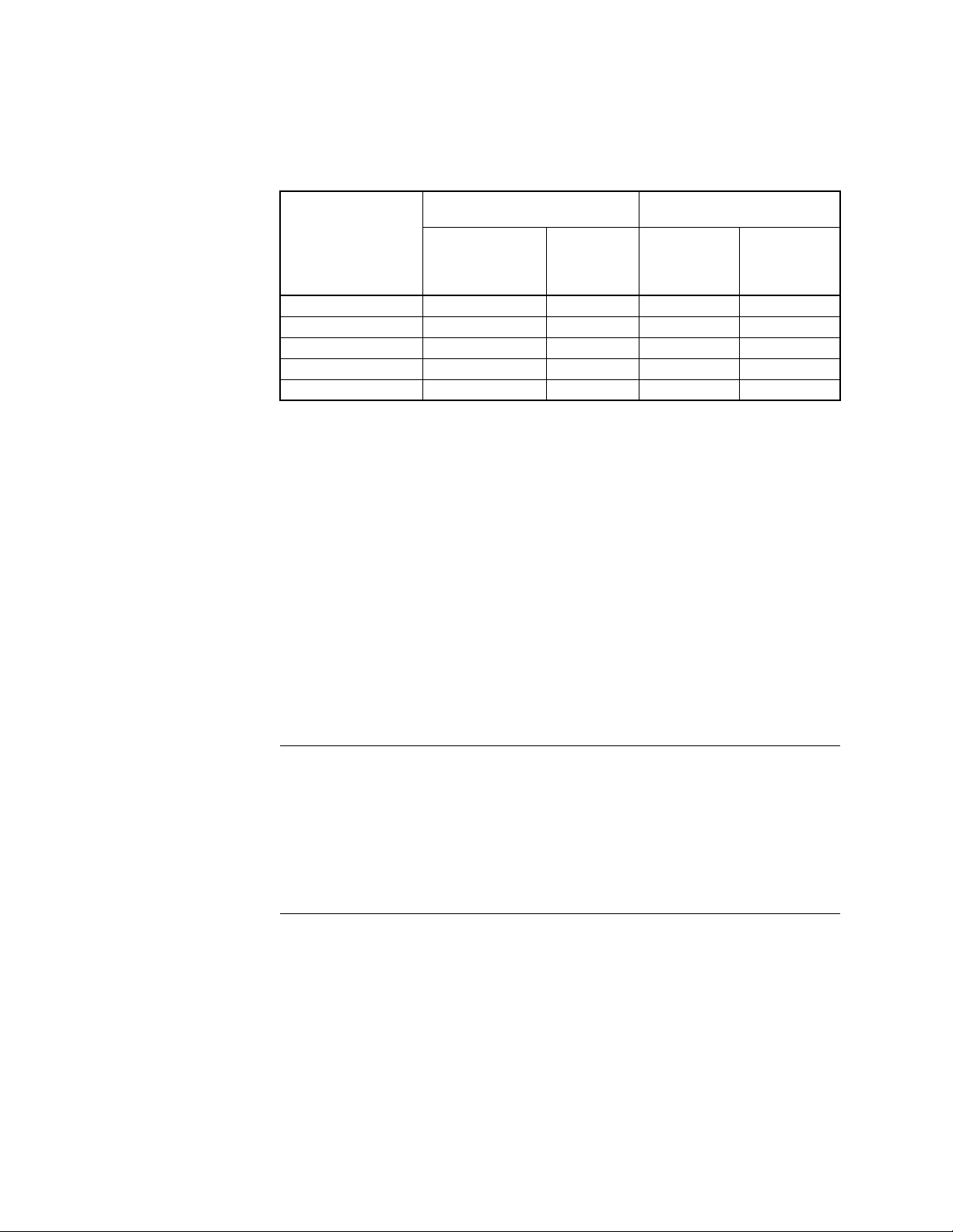
SPECIFICATIONS
Temperature Restrictions
Verify that temperature of the media in the valve versus the ambient temperature at the
actuator does not exceed the ratings shown in
Table-1 Restrictions on the Maximum Ambient Temperature for the Valve Actuator.
Table-1.
Maximum
Temperature of Media
in the Valve Body
(Check Ratings
of the Valve)
366°F (180°C) Do Not Use 88°F (31°C) 90°F (32°C) 90°F (32°C)
340°F (171°C) Do Not Use 93°F (34°C) 100°F (38°C) 100°F (38°C)
281°F (138°C) Do Not Use 103°F (39°C) 115°F (46°C) 140°F (60°C)
181°F (83°C) Do Not Use 120°F (48°C) 140°F (60°C)c140°F (60°C)
80°F (26°C) 140°F (60°C)
a
For detailed valve linkage installation instructions, refer to AV-600 Hydraulic Actuator Valve Linkage Kit
General Instructions, F-26279.
b
For detailed valve linkage installation instructions, refer to AV-7600 Hydraulic Actuator Valve Linkage Kit
General Instructions, F-26235.
c
Maximum allowable ambient temperature of the actuator.
Maximum Ambient Temperature of
MF-5X13, MP-541X, or MPR-5X1X
AV-600a or
AV-7600b Only for
Chilled Water
Applications Only
AV-600a or
AV-7600
& AV-601
c
140°F (60°C)c140°F (60°C)c140°F (60°C)
Maximum Ambient Temperature
of MA-521X or MP-521X
AV-600a or
b
AV-7600b Only
AV-600a or
AV-7600
& AV-601
b
INSTALLATION
Inspection Inspect the package for damage. If damaged, notify the appropriate carrier immediately.
If undamaged, open the package and inspect the device for obvious damage. Return
damaged products.
Requirements • Tools (not provided):
– Two (2) 3/8" wrenches
– TOOL-19, 1/8" diameter rod
– TOOL-20-1, Packing and linkage wrench
– TOOL-37, 1-5/8" open-ended wrench (optional)
– 6" or longer ruler
• Training: Installer must be a qualified, experienced technician.
c
c
c
Caution:
• Avoid locations where excessive moisture, corrosive fumes, or vibration is present.
• Install all two-way valves so that they close against the flow. An arrow on the valve body
or a tag indicates the proper flow direction.
• Always install three-way mixing valves with two inlets and one outlet.
• Always install three-way diverting valves with one inlet and two outlets.
• Do not install the actuator below the center line of the valve. For steam applications
mount the actuators above the valve body at 45° from vertical.
2 © Copyright 2010 Schneider Electric All Rights Reserved. F-26280-3
Page 3

Extension Installation
Spacer
Mounting
Bracket
Refer to Figure-1 when installing the AV-601 Linkage Extension.
Figure-1 Installation of AV-601.
1. If the actuator is installed on the valve body, it must be removed by unscrewing the mounting nut on the valve.
MAINTENANCE
Caution: Do not twist or exert any force on the actuator housing during installation. Either
turn the base of the actuator by hand or, if necessary, use a 1-5/8" open end wrench
(TOOL-37) on flats provided on the actuator base and valve body mounting nut.
2. Insert the AV-601 mounting bracket over the previously assembled AV -600 or AV-7600 valve linkage.
3. Screw the mounting bracket on to the valve body mounting nut.
4. Insert the spacer from the AV-601 into the mounting bracket.
5. The actuator is attached by screwing the mounting bracket into the base of the actuator. The actuator may be rotated as desired for ease in making wiring connections.
Note: The AV-601 linkage adds 2-1/32" (52 mm) to the height of the valve assembly.
In environments where condensate exists and the actuator is mounted at an angle from
vertical, position the weep hole of the AV-601 to obtain maximum drainage. Do not trap
moisture by insulating above mounting nut.
The Actuator Linkage requires no maintenance.
Regular maintenance of the total system is recommended to assure sustained, optimum
performance. Hard water leaves abrasive deposits and reduces component life. To
maximize valve life consult EN-205, Water System Guidelines, F-26080.
F-26280-3 © Copyright 2010 Schneider Electric All Rights Reserved. 3
Page 4

On October 1st, 2009, TAC became the Buildings business of its parent company Schneider Electric. This document reflects the visual identity of Schneider Electric,
however there r emains r eferences to T AC as a corporate brand in the body copy. As each document is updated, the bo dy co py will be change d to refl ect app ropriate
corporate brand changes.
Copyright 2010, Schneider Electric
All brand names, trademarks and registered
trademarks are the property of their respective
owners. Information contained within this
document is subject to change without notice.
F-26280-3
 Loading...