

Application
The AV-600 linkage is used to field assemble
MA-521x, MF-5x13, MP-521x, MP-541x, MPR-561x,
MPR-571x, and MPR-581x round hydraulic actuators
to 1/2" through 2" VB-7xxx and obsolete VB-9xxx twoway and three-way valve bodies.
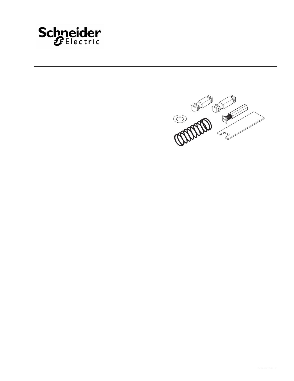
AV-600
Hydraulic Actuator Valve LInkage Kit
General Instructions
Features
• AV-600 provides direct couple interface between
MA, MF, MP, and MPR-5xxx actuators and 1/2" to
1-1/4" VB-7xxx valve bodies.
Applicable Literature
• Environmental Controls Cross-Reference Guide, F-
23638
• Environmental Controls Reference Manual,
F-21683
• Environmental Controls Application Manual,F-
21335
• Pneumatic Products Catalog, F-27383
• Environmental Controls Valve Selection Guide, F-
26094
• EN-205 Water System Guidelines, F-26080
• A V-601 Linkage Extension Kit General Instructions,
F-26280
Printed in U.S.A. 4/10 © Copyright 2010 Schneider Electric All Rights Reserved. F-26279-4
F-26279-4
SPECIFICATIONS
Temperature Restrictions
Verify that temperature of the media in the valve versus the ambient temperature at the
actuator does not exceed the ratings shown in
Table-1 Restrictions on the Maximum Ambient Temperature for the Valve Actuator.
Table-1.
Maximum
Temperature of Media
in the Valve Body
(Check Ratings
of the Valve)
366°F (180°C) Do Not Use 88°F (31°C) 90°F (32°C) 90°F (32°C)
340°F (171°C) Do Not Use 93°F (34°C) 100°F (38°C) 100°F (38°C)
281°F (138°C) Do Not Use 103°F (39°C) 115°F (46°C) 140°F (60°C)
181°F (83°C) Do Not Use 120°F (48°C) 140°F (60°C)b140°F (60°C)
80°F (26°C) 140°F (60°C)
a
For applications requiring AV-601 refer to AV-601, Linkage Extension Kit General Instructions, F-26280.
b
Maximum allowable ambient temperature of the actuator.
Maximum Ambient Temperature of
MF-5x13, MP-541x, or MPR-5x1x
AV-600 Only for
Chilled Water
Applications Only
b
AV-600
& AV-601
140°F (60°C)b140°F (60°C)b140°F (60°C)
Maximum Ambient Temperature
of MA-521x or MP-521x
AV-600 Only
a
& AV-601
AV-600
Close-off Pressure Rating
Close-off pressure ratings are listed in Table-2 and Table-3. For current valve bodies, make
sure the close-off pressure is adequate for the application.
Required Components
AM-602 Adaptor for current actuators to obsolete linkages. See Figure-7 through Figure-9.
AM-603 Adaptor for obsolete actuators to AV-600. See Figure-7 through Figure-9.
AV-601 Linkage Extension Kit
INSTALLATION
Inspection Inspect the package for damage. If damaged, notify the appropriate carrier immediately.
If undamaged, open the package and inspect the device for obvious damage. Return
damaged products.
a
b
b
b
Requirements • Tools (not provided):
– Two (2) 3/8" wrenches
– TOOL-19, 1/8" diameter rod
– TOOL-20-1, Packing and linkage wrench
– TOOL-37, 1-5/8" open-ended wrench (optional)
– 6" or longer ruler
• Linkage wrench (provided)
• Training: Installer must be a qualified, experienced technician.
Caution:
• Avoid locations where excessive moisture, corrosive fumes, or vibration is present.
• Install all two-way valves so that they close against the flow. An arrow on the valve body
or a tag indicates the proper flow direction.
• Always install three-way mixing valves with two inlets and one outlet.
• Always install three-way diverting valves with one inlet and two outlets.
• Do not install the actuator below the center line of the valve. For steam applications
mount the actuators above the valve body at 45° from vertical.
2 © Copyright 2010 Schneider Electric All Rights Reserved. F-26279-4
ASSEMBLY PROCEDURE
The AV-600 linkage kit contains parts for installation on both current 1/2" to 2" VB-7xxx
series valve bodies and on obsolete 1/2" to 1-1/4" VB-9xxx and older valve bodies.
AV-600 Valve Linkage Kit Used with VB-7xxx Series Valves
The AV-600 linkage kit used on VB-7xxx series valve bodies require no stem height setting.
Refer to Environmental Controls Valve Selection Guide, F-26094, for valves
accommodating the AV-60 0 linkage kit.
Caution:
• It is essential that the proper parts be used for the valve body on which the linkage is
being installed to ensure proper actuator operation and close off.
• Do not attempt to use the square stem extension with VB-7xxx valves. Parts or valves
may be damaged internally.
Linkage Installation
The linkage kit is assembled onto the VB-7xxx valve body with the stem in the up position.
1. Thread the hexagon coupler onto the valve stem all the way to the bottom of the stem thread, finger tight (Figure-1).
Spring
Compresion
Screw
Spring Retainer
Hexagon Coupler
1/16" Max.
(1.6 mm)
Figure-1 Installation of Hexagon Coupler and Spring Compression Screw.
Caution: The hexagon coupler must reach to within 1/16" (1.6 mm) of the smooth section
of the stem to assure proper seating. Do not use the Spring Compression Screw to run the
Hexagon Coupler down.
2. Start the spring compression screw one turn or more into the hexagon coupler. Pull the valve stem completely up.
3. Slip the spring over the coupler and screw.
4. Place the retainer over the screw. Twist the retainer 45° to lock it in place on the spring compression screw.
5. Insert the linkage wrench (supplied with kit, also included on TOOL-20-1) through the spring coils to hold hexagon coupler.
Valve Stem
F-26279-4 © Copyright 2010 Schneider Electric All Rights Reserved. 3
6. Tighten the spring compression screw. To establish proper linkage height, run the spring
Spring Retainer
(Turn 45 degrees to
lock in place)
Linkage Wrench
(Hold to prevent turning.)
Spring
Turn until Spring
Compression Screw
bottoms firmly on
valve stem
compression screw down until the screw end bottoms firmly on the stem top (Figure-2).
• On stem up closed valves (VB-722x) or 3-way valve (VB-73xx), you will feel the
screw bottom.
• On stem up open valve (VB-721x), the stem and hexagon coupler will begin to turn.
Figure-2 Completing Linkage Kit Assembly to Valve.
7. Confirm stem height setting: 2-5/16" (59 mm) maximum after installation on stem up open valves (VB-721x) 2-7/32" (56 mm) maximum on stem up closed (VB-722x) or 3-way (VB-73xx) valves.
8. Center the spring on top and bottom to assure smooth actuator operation. See Figure-3 for total assembly components required.
Actuator housing
Actuator base
Spring retainer
Spring
Spring
compression
screw
Hexagon coupler
4 © Copyright 2010 Schneider Electric All Rights Reserved. F-26279-4
Figure-3 Assembly of AV-600 Linkage Kit onto VB-7xxx Series Valve.
Packing nut
Mounting nut

AV-600 Linkage Used with VB-121, VB-324, and VB-9xxx Series Valves
Refer to the following tables to select compatible valves for the desired actuator using the
AV-600 linkage kit that require stem height settings. Refer to Table-2 for current valves.
Table-3 and Table-4 list the obsolete valve bodies using the AV-600 linkage kit. Follow the
assembly procedures on pages 8 through 10.
Use Table-1 to determine if AV-601 linkage extension kit is required for the application.
Consult Table-2, Table-3, and Table-4 to make sure the valve selected is compatible with
AV-600 valve linkage kit. Follow the assembly procedures on page 10.
For replacement of obsolete actuators and linkages, refer to Figure-7 through Figure-9 and
Table-3 or Table-4.
Table-2 Required Stem Height Settings for AV-600 with Current Valve Bodies.
Valve
Assembly Number
VA-1219
VP-1219
VA-3249
VP-3249
Valve Body
Part Number
VB-121-0-4-P
(P Code -1 to -3)
VB-324-0-5-4
Valve Body Type
(Normal Position)
2-Way
1/2" O.D. Flared Straightway
(Normal Open)
3-Way
1/2" O.D. Flared Mixing
Stem Height Setting for Dim. “x” in
inches (mm)
(Note: Use short stem extension 1-15/32".)
1-25/32 (45)
Stem Down
2-3/16 (56)
Stem Up
Table-3 Required Stem Height Settings for AV-600 with Obsolete Valve Bodies and Close-off Ratings for the
Combination of AV-600 Valve Body and Actuator Combination.
MA-521x
Series
Valve Linkages Required AV-600 AV-600 AV- 600 & AV-601
VALVE BODY INFORMATION
Valve Body
Part Number
VB-111-0-3-1
VB-111-0-3-2 1.3 1/2" 100 100 100
VB-111-0-3-3 2.2 1/2" 100 100 100
VB-111-0-3-4 3.8 1/2" 100 100 100
VB-111-0-3-5 5.5 3/4" 80 80 80
VB-111-0-3-6 7.5 3/4" 80 80 80
VB-111-0-3-7 8.5 1" 45 45 45
VB-111-0-3-8 10.5 1" 45 45 45
VB-111-0-3-9 15 1-1/4" 25 25 25
VB-9211-0-4-1
VB-9211-0-4-2 1.3 1/2" 180 190 190
VB-9211-0-4-3 2.2 1/2" 180 190 190
VB-9211-0-4-4 3.3 1/2" 180 190 190
VB-9211-0-4-5 5 3/4" 75 85 85
VB-9211-0-4-6 6.2 3/4" 75 85 85
VB-9211-0-4-7 8.2 1" 40 45 45
VB-9211-0-4-8 10.5 1" 40 45 45
VB-9211-0-4-9 15 1-1/4" 25 30 30
VB-9212-0-4-1
VB-9212-0-4-2 1.3 5/8" O.D. 180 190 190
VB-9212-0-4-3 2.2 5/8" O.D. 180 190 190
VB-9212-0-4-4 3.3 5/8" O.D. 180 190 190
VB-9213-0-4-1
VB-9213-0-4-2 1.3 1/2" 180 190 190
VB-9213-0-4-3 2.2 1/2" 180 190 190
VB-9213-0-4-4 3.6 1/2" 180 190 190
VB-9213-0-4-5 5 3/4" 75 85 85
VB-9213-0-4-6 6.2 3/4" 75 85 85
VB-9213-0-4-7 8.2 1" 40 45 45
VB-9213-0-4-8 11 1" 40 45 45
VB-9213-0-4-9 16 1-1/4" 25 30 30
Description Cv Size
0.4 1/2" 100 100 100
2-Way
Normally Open
Union End NPT
Angle Body
0.4 1/2" 180 190 190
2-Way
Normally Open
Union End NPT
Straightway Body
2-Way
Normally Open
SAE 45° Flared
Straightway Body
2-Way
Normally Open
FNPT
Straightway Body
0.4 5/8" O.D. 180 190 190
0.4 1/2" 180 190 190
ACTUATORS
MP-521x
Series
CLOSE-OFF PRESSURE (psi)
MF-5x13, MP-541x
& MPR-5xxx
Stem Height
Setting for
AV -600 Dimension
a
(Note: Use short
stem extension
1-15/32".)
1-13/16"
Stem Down
1-25/32"
Stem Down
1-25/32"
Stem Down
1-25/32"
Stem Down
“x”
F-26279-4 © Copyright 2010 Schneider Electric All Rights Reserved. 5

Table-3 Required Stem Height Settings for AV-600 with Obsolete Valve Bodies and Close-off Ratings for the
Combination of AV-600 Valve Body and Actuator Combination. (Continued)
ACTUATORS
MA-521x
Series
Valve Linkages Required AV-600 AV-600 AV-600 & AV-601
VALVE BODY INFORMATION
Valve Body
Part Number
VB-9214-0-4-1
VB-9214-0-4-2 1.3 1/2" 180 190 190
VB-9214-0-4-3 2.2 1/2" 180 190 190
VB-9214-0-4-4 3.6 1/2" 180 190 190
VB-9214-0-4-5 5 3/4" 75 85 85
VB-9214-0-4-6 6.2 3/4" 75 85 85
VB-9214-0-4-7 8.2 1" 40 45 45
VB-9214-0-4-8 11 1" 40 45 45
VB-9214-0-4-9 16 1-1/4" 25 30 30
VB-9221-0-4-1
VB-9221-0-4-2 1.3 1/2" 250 220 220
VB-9221-0-4-3 2.2 1/2" 250 220 220
VB-9221-0-4-4 3.3 1/2" 250 220 220
VB-9221-0-4-5 5 3/4" 140 90 90
VB-9221-0-4-6 6.2 3/4" 140 90 90
VB-9221-0-4-7 8.2 1" 75 50 50
VB-9221-0-4-8 10.5 1" 75 50 50
VB-9221-0-4-9 15 1-1/4" 45 30 30
VB-9222-0-4-1
VB-9222-0-4-2 1.3 5/8" O.D. 250 220 220
VB-9222-0-4-3 2.2 5/8" O.D. 250 220 220
VB-9222-0-4-4 3.3 5/8" O.D. 250 220 220
VB-9223-0-4-1
VB-9223-0-4-2 1.3 1/2" 250 220 220
VB-9223-0-4-3 2.2 1/2" 250 220 220
VB-9223-0-4-4 3.6 1/2" 250 220 220
VB-9223-0-4-5 5 3/4" 140 90 90
VB-9223-0-4-6 6.2 3/4" 140 90 90
VB-9223-0-4-7 8.2 1" 75 50 50
VB-9223-0-4-8 11 1" 75 50 50
VB-9223-0-4-9 16 1-1/4" 45 30 30
VB-9224-0-4-1
VB-9224-0-4-2 1.3 1/2" 250 220 220
VB-9224-0-4-3 2.2 1/2" 250 220 220
VB-9224-0-4-4 3.6 1/2" 250 220 220
VB-9224-0-4-5 5 3/4" 140 90 90
VB-9224-0-4-6 6.2 3/4" 140 90 90
VB-9224-0-4-7 8.2 1" 75 50 50
VB-9224-0-4-8 11 1" 75 50 50
VB-9224-0-4-9 16 1-1/4" 45 30 30
VB-9253-0-4-1
VB-9253-0-4-2 1.3 1/2" 180 190 190
VB-9253-0-4-3 2.2 1/2" 180 190 190
VB-9253-0-4-4 3.6 1/2" 180 190 190
VB-9253-0-4-5 5 3/4" 75 85 85
VB-9253-0-4-6 6.2 3/4" 75 85 85
VB-9253-0-4-7 8.2 1" 40 45 45
VB-9253-0-4-8 11 1" 40 45 45
VB-9253-0-4-9 16 1-1/4" 25 30 30
Description Cv Size
0.4 1/2" 180 190 190
2-Way
Normally Open
Union Sweat
Straightway Body
0.4 1/2" 250 220 220
2-Way
Normally Closed
Union End NPT
Straightway Body
2-Way
Normally Closed
SAE 45° Flared
Straightway Body
2-Way
Normally Closed
FNPT
Straightway Body
2-Way
Normally Closed
Union Sweat
Straightway Body
2-Way
Normally Open
FNPT
Straightway Body
Stainless Steel Trim
Teflon Disc
0.4 5/8" O.D. 250 220 220
0.4 1/2" 250 220 220
0.4 1/2" 250 220 220
0.4 1/2" 180 190 190
MP-521x
Series
CLOSE-OFF PRESSURE (psi)
MF-5x13, MP-541x
& MPR-5xxx
Stem Height
Setting for
AV -600 Dimension
a
(Note: Use short
stem extension
1-15/32".)
1-25/32"
Stem Down
Stem Up
Stem Up
Stem Up
Stem Up
1-25/32"
Stem Down
“x”
2-1/8"
2-1/8"
2-1/8"
2-1/8"
6 © Copyright 2010 Schneider Electric All Rights Reserved. F-26279-4

Table-3 Required Stem Height Settings for AV-600 with Obsolete Valve Bodies and Close-off Ratings for the
Combination of AV-600 Valve Body and Actuator Combination. (Continued)
ACTUATORS
MA-521x
Series
MP-521x
Series
MF-5x13, MP-541x
& MPR-5xxx
Valve Linkages Required AV-600 AV-600 AV-600 & AV-601
VALVE BODY INFORMATION
Valve Body
Part Number
VB-9263-0-4-1
Description Cv Size
0.4 1/2" 250 220 220
CLOSE-OFF PRESSURE (psi)
VB-9263-0-4-2 1.3 1/2" 250 220 220
VB-9263-0-4-3 2.2 1/2" 250 220 220
VB-9263-0-4-4 3.6 1/2" 250 220 220
VB-9263-0-4-5 5 3/4" 140 90 90
VB-9263-0-4-6 6.2 3/4" 140 90 90
VB-9263-0-4-7 8.2 1" 75 50 50
2-Way
Normally Closed
FNPT
Straightway Body
Stainless Steel Trim
Teflon Disc
VB-9263-0-4-8 11 1" 75 50 50
VB-9263-0-4-9 16 1-1/4" 45 30 30
VB-9273-0-4-1
0.4 1/2" 180 190 190
VB-9273-0-4-2 1.3 1/2" 180 190 190
VB-9273-0-4-3 2.2 1/2" 180 190 190
VB-9273-0-4-4 3.6 1/2" 180 190 190
VB-9273-0-4-5 5 3/4" 75 85 85
VB-9273-0-4-6 6.2 3/4" 75 85 85
VB-9273-0-4-7 8.2 1" 40 45 45
2-Way
Normally Open
FNPT
Straightway Body
Stainless Steel Trim
VB-9273-0-4-8 11 1" 40 45 45
VB-9273-0-4-9 16 1-1/4" 25 30 30
VB-9283-0-4-1
0.4 1/2" 250 220 220
VB-9283-0-4-2 1.3 1/2" 250 220 220
VB-9283-0-4-3 2.2 1/2" 250 220 220
VB-9283-0-4-4 3.6 1/2" 250 220 220
VB-9283-0-4-5 5 3/4" 140 90 90
VB-9283-0-4-6 6.2 3/4" 140 90 90
VB-9283-0-4-7 8.2 1" 75 50 50
2-Way
Normally Closed
FNPT
Straightway Body
Stainless Steel Trim
VB-9283-0-4-8 11 1" 75 50 50
VB-9283-0-4-9 16 1-1/4" 45 30 30
VB-9312-0-4-2
VB-9312-0-4-4 4 5/8" O.D. 100 100 100
3-Way Mixing
SAE 45° Flared
Normal Position
Flow B to AB
VB-9313-0-4-2
VB-9313-0-4-4 4 1/2" 100 100 100
VB-9313-0-4-6 6.8 3/4" 55 55 55
VB-9313-0-4-8 12 1" 35 35 35
3-Way Mixing
FNPT
Normal Position
Flow B to AB
2 5/8" O.D. 100 100 100
2 1/2" 100 100 100
VB-9313-0-4-9 16 1-1/4" 22 22 22
VB-9314-0-4-2
VB-9314-0-4-4 4 1/2" 100 100 100
VB-9314-0-4-6 6.8 3/4" 55 55 55
VB-9314-0-4-8 12 1" 35 35 35
3-Way Mixing
Union Sweat
Normal Position
Flow B to AB
2 1/2" 100 100 100
VB-9314-0-4-9 16 1-1/4" 22 22 22
VB-9323-0-4-4
VB-9323-0-4-6 8 3/4" 250 250 250
VB-9323-0-4-8 12 1" 250 250 250
VB-9323-0-4-9 16 1-1/4" 250 250 250
VB-9332-0-4-2
VB-9332-0-4-3
VB-9332-0-4-4 4 5/8" O.D. 35 35
a
For applications requiring AV-601 refer to AV-601, Linkage Extension Kit General Instructions, F-26280.
b
Depress stem to lower seat, release stem, and adjust height in this position.
3-Way Diverting
FNPT
Normal Position
Flow B to AB
3-Way Sequencing
45° SAE Flared
Normal Position
Flow B to AB
6 1/2" 250 250 250
1.7 5/8" O.D.
2.4 5/8" O.D. 35 35
Not Available
35 35
Stem Height
Setting for
AV -600 Dimension
a
(Note: Use short
stem extension
1-15/32".)
Stem Up
1-25/32"
Stem Down
Stem Up
Stem Up
Stem Up
Stem Up
Stem Up
1-15/16"
“x”
2-1/8"
2-1/8"
2-1/8"
2-1/8"
2-1/8"
2-1/8"
b
F-26279-4 © Copyright 2010 Schneider Electric All Rights Reserved. 7

Table-4 Required Stem Height Setting for AV-600 with Obsolete Valve Bodies
(Note: Use the long stem extension 1-21/32".)
Valve Body
Part Number
Series
VB-111-0-3-P VA-1102, VA-1112, VP-1112 2-Way, Normally Open, Union End, Angle 1-7/32"Stem Down 1-13/16"Stem Down
VB-111-0-4-P VA-1102, VA-1112, VP-1112 2-Way, Normally Open, Union End, Stwy 1-7/32"Stem Down 1-13/16"Stem Down
VB-121-0-3-P VA-1212, VP-1212 2-Way, N.O., 1/2" O.D. Flared, Angle 1-7/32"Stem Down 1-13/16"Stem Down
VB-121-0-4-P VA-1212, VP-1212 2-Way, N.O., 1/2" O.D. Flared, Straightway 1-7/32"Stem Down 1-13/16"Stem Down
VB-131-001-3-4 VA-1302, VP-1312 2-Way, N.O., 5/8" O.D. Flared, Angle 1-11/32"Stem Down 1-13/16"Stem Down
VB-131-001-3-7 VA-1302, VP-1312 2-Way, N.O., 7/8" O.D. Flared, Angle 1-9/32"Stem Down 1-13/16"Stem Down
VB-131-001-4-P VA-1302, VP-1312 2 -Way, Normally Open, Flared, Straightway 1-7/32"Stem Down 1-13/16"Stem Down
VB-131-002-3-4 VA-1302, VP-1312 2-Way, N.C., 5/8" O.D. Flared, Angle 1-11/32"Stem Down 2-1/8"Stem Up
VB-131-002-3-7 VA-1302, VP-1312 2-Way, N.C., 7/8" O.D. Flared, Angle 1-9/32"Stem Down 2-1/8"Stem Up
VB-131-002-4-P VA-1302, VP-1312 2-Way, Normally Closed, Flared, Straightway 1-9/16"Stem Up 2-1/8"Stem Up
VB-151-0-1-P VA-1512, VP-1512 2-Way, Normally Closed, FNPT, Straightway 1-17/32"Stem Up 2-1/8"Stem Up
OYBB-233-4 VA-2402, VP-2452 2-Way, Normally Closed, 1/2" FNPT, Stwy 1-9/32"Stem Down 2-1/8"Stem Up
OYBB-233-7 VA-2402, VP-2452 2-Way, Normally Closed, 3/4" FNPT, Stwy 1-5/32"Stem Down 2-1/8"Stem Up
VB-314-0-1-4 VA-3142, VP-3142 3-Way, Mixing, 1/2" FNPT 1-11/32"Stem Down 2-1/8"Stem Up
VB-314-0-1-7 VA-3142, VP-3142 3-Way, Mixing, 3/4" FNPT 1-9/32"Stem Down 2-1/8"Stem Up
VB-314-0-1-8 VA-3142, VP-3142 3-Way, Mixing, 1" FNPT 1-9/32"Stem Down 2-1/8"Stem Up
VB-324-0-5-4 VA-3242, VP-3242 3-Way, Mixing, 1/2" O.D., Flared 1-11/32"Stem Down 2-13/16"Stem Up
VB-334-0-5-4 VP-3342 3-Way, Sequencing, 1/2" O.D. Flared 2-3/8"
VB-354-0-5-4 VA-3542, VP-3542 3-Way, Mixing, 5/8" O.D. Flared 1-11/32"Stem Down 2-1/8"Stem Up
VB-354-0-5-7 VA-3542, VP-3542 3-Way, Mixing, 7/8" O.D. Flared 1-9/32"Stem Down 2-1/8"Stem Up
VB-701-0-5-P VP-7012 4-Pipe Valve 2-3/8"
VB-711-0-5-P VP-7112 5-Pipe Valve 2-3/8"
a
Use the locknut enclosed in the coin envelope. Do not break the locknut on the stem extension.
b
Depress stem to lower seat, release stem, and adjust height in this position.
Valve Assembly
Part Number Series
Description of Valve Body
Obsolete Linkage
Stem Height Setting
Dimension “x”
b
b
b
AV-600
Stem Height Setting
Dimension “x”
a
1-15/16"
1-15/16"
1-15/16"
b
a
b
b
Caution:
• It is essential that the proper parts be used for the valve body on which the linkage is
being installed to ensure proper actuator operation and close off.
• Do not attempt to use the hexagon coupler and spring compression screw with
VB-121, VB-324, or VB-9xxx valves. Stroke or close off maybe affected.
Linkage Installation
The AV-600 linkage includes of two (2) different lengths of combination square stem
extension and breakaway locknut, spring, spring retainer, and a locknut (used with certain
obsolete valve bodies only).
1. Select the correct square stem extension.
• The short square stem extension [1-15/32" (37.3 mm)] is used with the obsolete
VB-9xxx valves shown in Table-3.
• The long stem extension [1-21/32" (42 mm)] is used with current VB-121 and
VB-324 valves shown in Table-2 and obsolete VB-9xxx valve bodies shown in
Table-4.
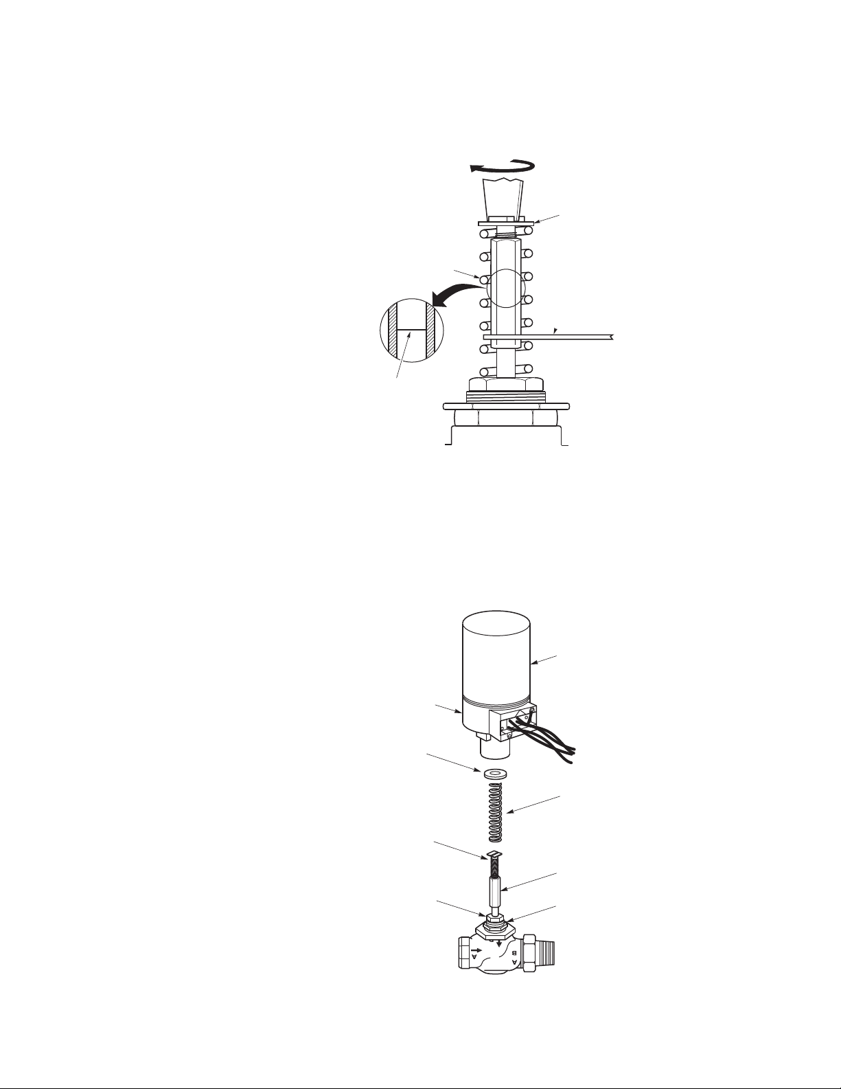
2. Thread the correct stem extension several threads on to the valve stem (Figure-4).
8 © Copyright 2010 Schneider Electric All Rights Reserved. F-26279-4

Figure-4 Installation of AV-600.
Actuator Base
Packing Nut
Actuator Housing
Spring Retainer
Spring
Combination Square Stem
Extension and Locknut
Mounting Nut
g
3. Position the valve stem as indicated for the appropriate valve body shown in Table-3 or Table-4, stem up or stem down.
Caution: Do not twist or exert any force on the actuator housing during installation
(Figure-4). Either turn the base of the actuator by hand or, if necessary, use a 1-5/8" open
end wrench (TOOL-37) on flats provided on the actuator base and valve body mounting nut
(Figure-4).
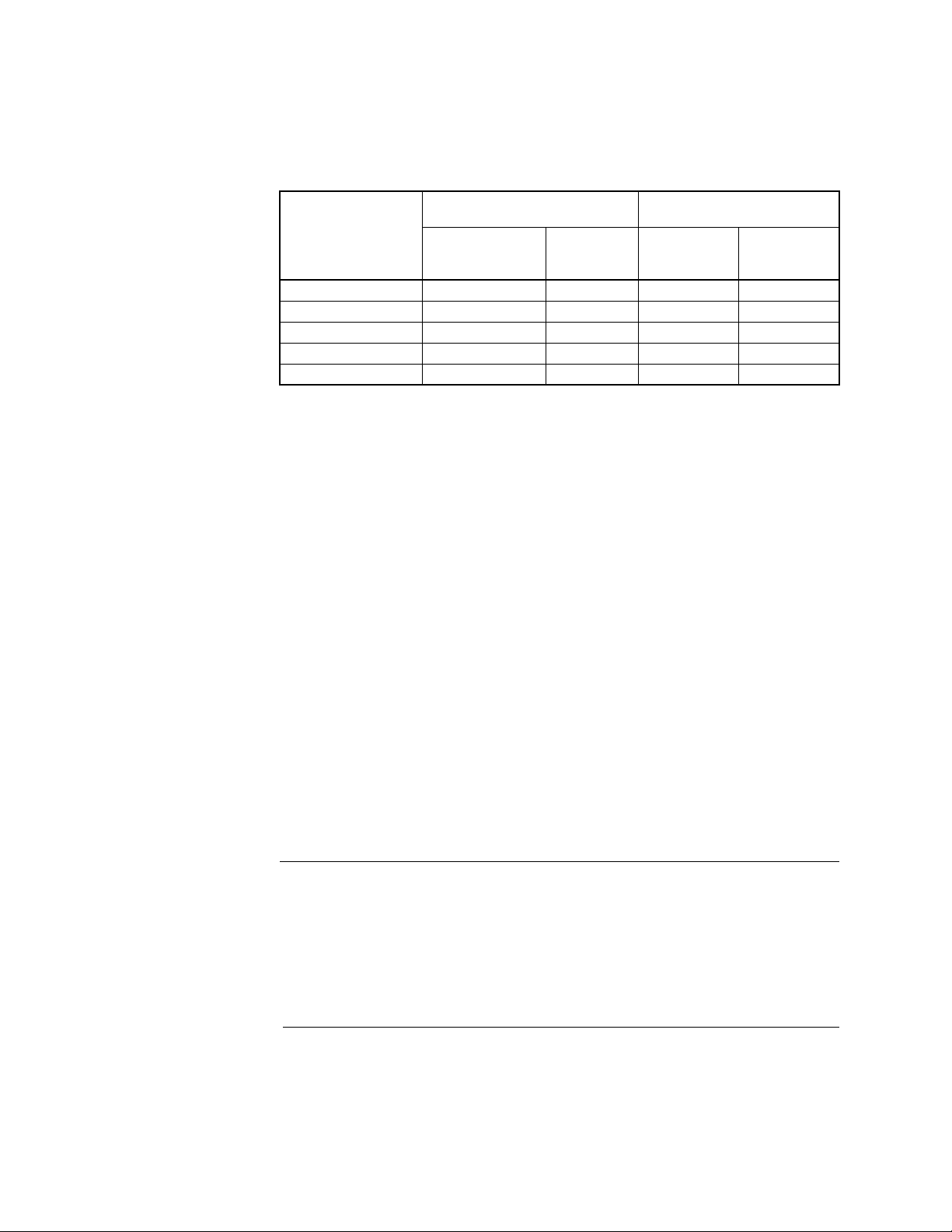
4. Adjust the height of the stem extension to the “x” dimension shown in Table-3 or Table-4 for the appropriate valve body. The “x” dimension is from the top of the stem extension to the top of the valve packing nut (Figure-5).
Stem Extension
Point A
Top Surface of
Stem Extension
Top Surface of
Packin
Nut
Figure-5 Height Adjustment of Combination Stem Extension and Locknut.
X
Point B
Packing Nut
Valve
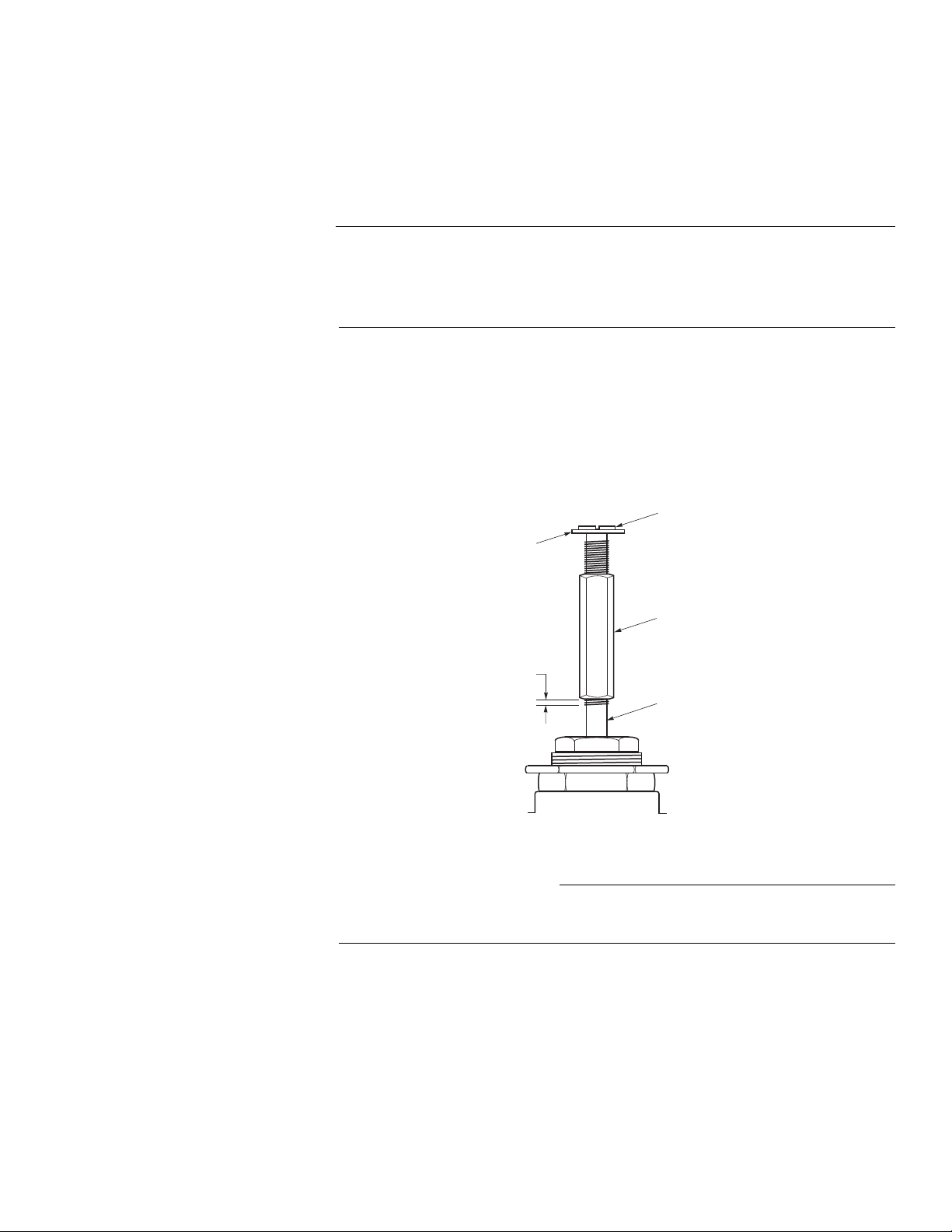
5. Using one 3/8" wrench on the square stem extension and one on the locknut, hold the
wrench stationary at the stem extension while turning the wrench at the locknut
clockwise. The locknut should separate from the stem extension. Next, while still
holding the wrench stationary at the stem extension, turn the wrench at the locknut
counterclockwise to jam the locknut against the stem extension, securing it in position.
F-26279-4 © Copyright 2010 Schneider Electric All Rights Reserved. 9

6. With the valve stem in the up position, place the spring over the valve stem
Tool-19 or 1/8" (3 mm) Dia. Rod
CW
Move Spring Up
to Lock Retainer
in Place
CCW
Move Spring Down
to Install or Remove
Retainer
Current
MA-521x-xxx-0-2
MF-5x13
MP-521x-xxx-0-2
MP-541x
MPR-581x
MPR-591x
Note: When replacing MP-521x-xxx with MP-5x1x-0-2, consult EN-111, System 8000 Electronic Control, F-15264.
Obsolete
MA-521x-xxx
MP-521x-xxx
MP-521x-xxx-0-1
(Figure-4).
7. Insert TOOL-19, 1/8" (3 mm) diameter rod, through the spring coil and through the hole in the stem extension (Figure-6).
Figure-6 Installation of Spring and Spring Retainer.
8. Hold the spring to keep it from turning and “walk” the to ol up the spring by turning it counterclockwise. Pushing down on the tool reduces the torque required to turn the stem and plug into the seat.
9. Set the retainer over the stem extension when the boss on the stem extension projects above the top of the spring coil.
10. Turn the retainer 45° to lock it in place.
11. Turn the tool clockwise down the spring coil to release the tension. Remove the tool from the assembly.
12. If AV-601 linkage extension is required, refer to the AV-601 the installation instructions contained in AV-601, Linkage Extension Kit General Instructions, F-26280.
13. The actuator is attached by screwing the mounting nut of the valve into the base of the actuator. The actuator may be rotated as desired for ease in making wiring connections.
MAINTENANCE
3/4"
(19 mm)
The actuator linkage requires no maintenance.
Regular maintenance of the total system is recommended to assure sustained, optimum
performance. Hard water leaves abrasive deposits and reduces component life. To
maximize valve life consult EN-205, Water System Guidelines, F-26080.
1-5/16"
(33 mm)
Figure-7 Identification of Obsolete and Current Actuators.
10 © Copyright 2010 Schneider Electric All Rights Reserved. F-26279-4

1-5/8"
AM-603
To adapt AV-600 to
obsolete actuators.
(41mm approx.)
2-3/16"
(56mm approx.)
2-3/16"
(56mm approx.)
1-5/8"
(41mm approx.)
Obsolete Linkages
AV-315, AV-317, AV-319-10,
& AV-319-20
Square Stem
Extension
Hexagon Coupler
Current Linkage
AV-600
Figure-8 Identification of Obsolete Valve Linkages and Current AV-600.
Spacer
AM-602
To adapt current
actuators to
obsolete linkages.
Figure-9 Adaptors for Obsolete Linkages and Actuators.
F-26279-4 © Copyright 2010 Schneider Electric All Rights Reserved. 11

On October 1st, 2009, TAC became the Buildings business of its parent company Schneider Electric. This document reflects the visual identity of Schneider Electric,
however there remains references to TAC as a corporate brand in the body copy. As each document is updated, the body copy will be changed to refl e ct appropriate
corpo r at e br a nd ch a nges.
Copyright 2010, Schneider Electric
All brand names, trademarks and registered
trademarks are the property of their respective
owners. Information contained within this
document is subject to change without notice.
F-26279-4
 Loading...