

Page 1
Application
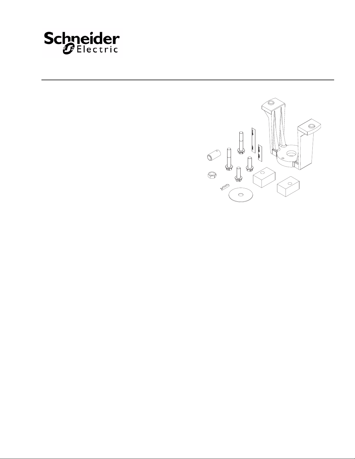
The AV-497 valve linkage kit is used to field assemble
MK-6811 actuators onto 2-1/2” to 5” VB-8xxx series
valves and MK-6911 actuators onto 6” VB-8xxx series
valves.
Features
• Die cast aluminum mounting bracket.
• Valve position indication provided as standard.
AV-497
Valve Linkage for MK-6811 and MK-6911
General Instructions
Printed in U.S.A. 6-10 Copyright 2010 Schneider Electric All Rights Reserved. F-27253-4
Page 2

Applicable Literature
F-Number Description Audience Purpose
Provides a comprehensive listing
of Schneider Electric component
F-27383 Pneumatic Products Catalog
F-27199 Vx-8xxx Series Selection Guide
F-27193 VB-8213 Flanged Valves General Instructions Describes the valve’s features,
F-27194 VB-8223 Flanged Valves General Instructions
F-27197 VB-8303 Flanged Valves General Instructions
F-13985
F-22909 AK-42309-500 Positive Positioner General Instructions
F-26080 EN-205 Water System Guidelines
MK-6600 Series, MK-6800 Series, MK-6911 Pneumatic
Actuators General Instructions
– Sales Personnel
– Application Engineers
– Installers
– Service Personnel
– Start-up Technicians
– Application Engineers
– Installers
– Service Personnel
– Start-up Technicians
products, describing their features
and specifications, and provides
other reference material useful to
their selection.
Provides features, specifications,
mounting dimensions, and other
criteria useful to the selection of
Vx-8xxx series valves.
specifications, and possible
applications. Provides
step-by-step mounting
instructions.
Describes the actuator’s features
and applications. Provides
step-by-step mounting
instructions.
Describes the positioner’s
features, specifications, and
possible applications. Provides
step-by-step mounting and
adjustment instructions.
Provides treatment guidelines for
water and steam systems.
2 Copyright 2010 Schneider Electric All Rights Reserved. F-27253-4
Page 3
SPECIFICATIONS
Refer to the VX-8XXX Selection Guide, F-27199, for information on close-off pressures,
temperature restrictions (ambient and fluid), and valve assembly dimensions.
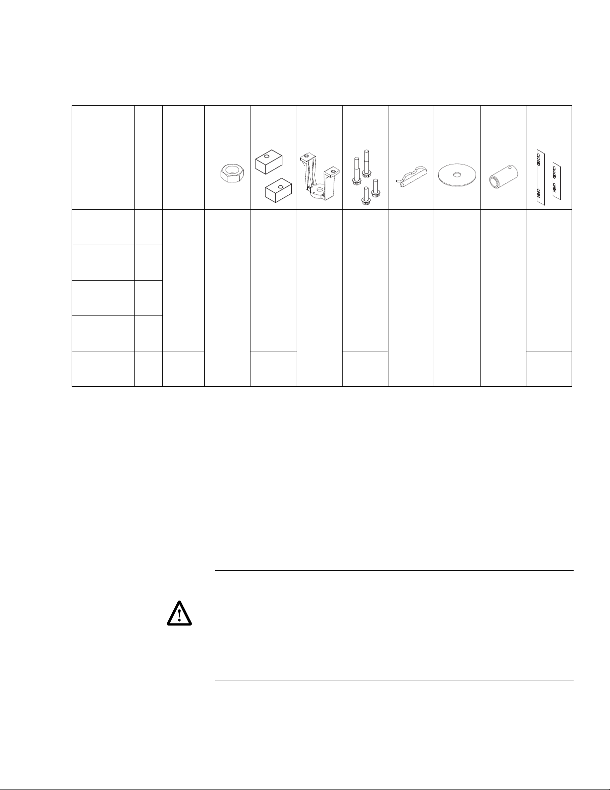
Table-1 AV-497 Valve Linkage Component Selection.
Valve
Valve Body
VB-8213-0-5-12
VB-8223-0-5-12
VB-8303-0-5-12
VB-8213-0-5-13
VB-8223-0-5-13
VB-8303-0-5-13
VB-8213-0-5-14
VB-8223-0-5-14
VB-8303-0-5-14
VB-8213-0-5-15
VB-8223-0-5-15
VB-8303-0-5-15
VB-8213-0-5-16
VB-8223-0-5-16
VB-8303-0-5-16
a
AK-42309-500 positive positioner optional.
b
AK-42309-500 positive positioner required.
Actuator
Size
2-1/2”
3”
MK-6811
4”
5”
6” MK-6911
Lock Nut
a
b
Stem
(1) 1/2”
Spacers
Not Used
(2)
Mounting
Bracket
(1)
Mounting
Bracket
Bolts
(2)
1-1/4”
Long
(2)
2-1/4”
Long
Connector
Pin
(1)
Indicating
Plate
(1) with
1/2” Hole
Stem
Extension
(1)
Scale
Length
1”
(25 mm)
2”
(51 mm)
INSTALLATION
Inspection Inspect the carton for possible damage. If damaged, notify the appropriate carrier
immediately. If undamaged, open the carton and inspect the kit for obvious damage. Return
any damaged products.
Requirements • Tools (not provided):
– Appropriate wrenches for stem extension, mounting bolts, and lock nuts.
• A source of pressurized air, suitable for applying air pressure to the actuator and
sufficient to fully stroke the piston.
• Training: Installer must be a qualified, experienced technician.
Location Caution:
• Avoid locations where excessive moisture, corrosive fumes, or vibration are present.
• Install all two-way valves so that they close against the flow. An arrow on the valve
indicates the proper direction of flow. Flow is from port A (inlet) to port AB (outlet).
• VB-8303 may be piped as a mixing valve (two inlets and one outlet) or a diverting valve
(one inlet and two outlets). Flow is from ports A and B to AB (mixing) and from AB to A
and B (diverting).
• Do not install the actuator below the center line of the valve. For steam applications,
mount the actuator on the valve body at 45 from vertical.
F-27253-4 Copyright 2010 Schneider Electric All Rights Reserved. 3
Page 4

Mounting Two-Way Normally Open 2-1/2” to 5” VB-8213 Valves
OPEN
CLOSED
OPEN
CLOSED
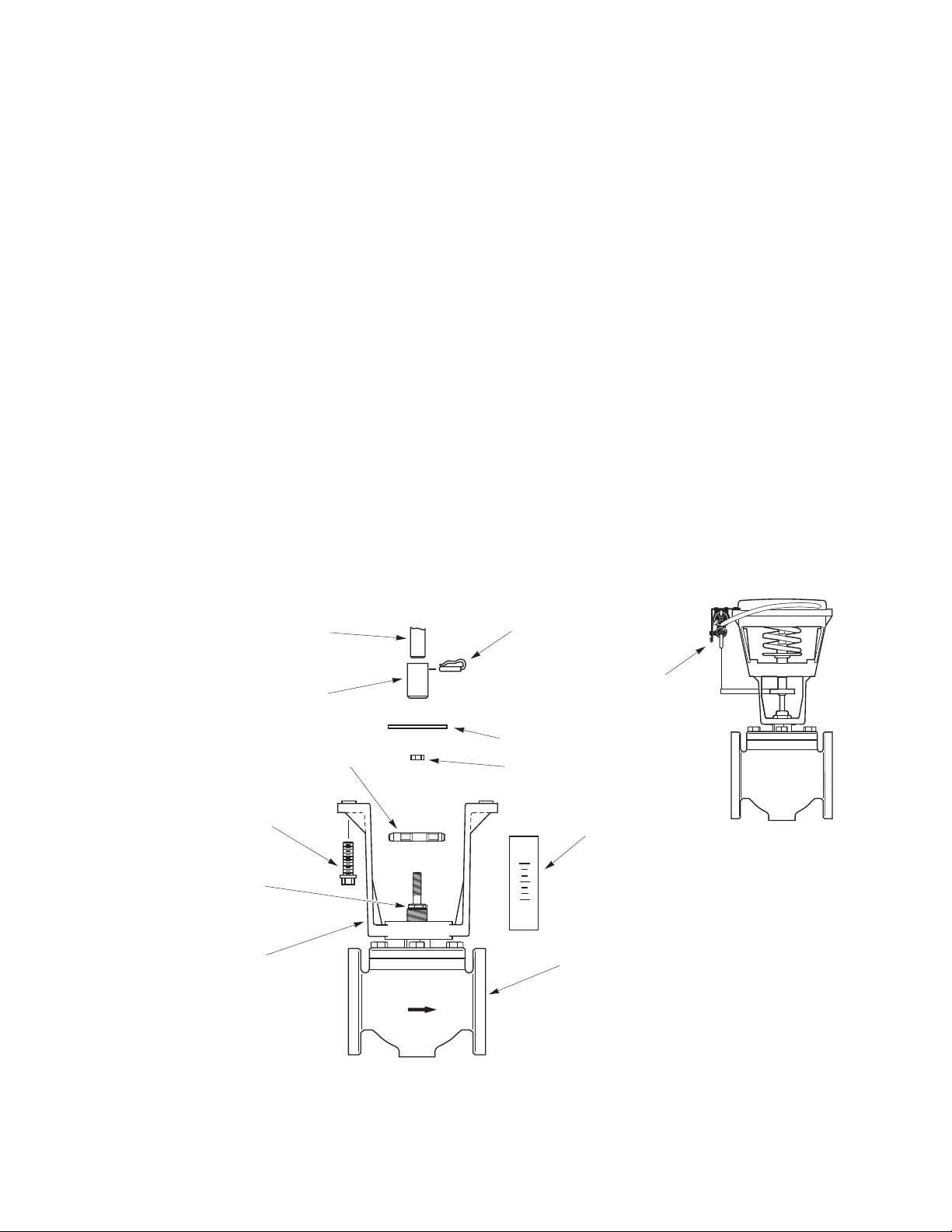
Connecting Pin
Indicator Plate
OPEN/CLOSED Decal
(Short)
Valve Body *
Mounting Bolt (2)
(1-1/4 long)
Bracket Nut *
Stem Locknut
Stem Extension
Actuator Piston Stem *
Mounting Bracket
Internal Packing Nut *
(Do not remove when
installing the linkage.)
Shown with
AK-42309-500
Positive Positioner
* Not included with AV-497
Linkage Kit
MK-6811 and AV-497
Assembled on
VB-8213 or VB-8303
(VB-8303 shown)
Figure-1 Valve Linkage Assembly for MK-6811 Actuator on 5” VB-8213 or VB-8303 Valve.
Refer to Figure-1.
1. Th e actuator should be in its fully retracted position (no air pressure).
2. Push the valve stem completely down so that the valve disc is seated against the valve
seat.
3. Moun t the bracket on the valve body by removing the bracket nut, placing the bracket
on the valve body, orienting the bracket in a convenient position for piping, and then
replacing and tightening the bracket nut.
4. Thread the 1/2” stem lock nut well down onto the valve stem. Next, place the indicator
plate (and the AK-42309-500 spring arm if positive positioner being used) on the valve
stem. Finally, thread the stem extension well down onto the valve stem. Consult the
AK-42309-500 Positive Positioner General Instructions, F-22909 for information on
mounting and calibrating the AK-42309-500 positive positioner.
5. Moun t the MK-6811 actuator to the mounting bracket, using the two 1-1/4” long bolts
provided.
6. Link the actuator to the valve stem extension as follows:
a. Apply air pressure to the actuator until it fully strokes (piston extended).
b. Turn the stem extension until the hole in the stem extension lines up with the hole
in the actuator piston.
c. Turn the stem extension two full turns up, toward the actuator piston.
d. Decrease air pressure in the actuator until the hole in the stem extension and the
hole in the actuator piston are aligned, and then insert the connecting pin.
7. Tighten the stem lock nut against the stem extension and indicator plate.
4 Copyright 2010 Schneider Electric All Rights Reserved. F-27253-4
Page 5
T wo-Way Normally Closed VB-8223 V alves and Three-W ay VB- 8303 2-1/2” to
OPEN
CLOSED
OPEN
CLOSED
Connecting Pin
Indicator Plate
OPEN/CLOSED Decal
(Short)
Valve Body *
Mounting Bolt (2)
(1-1/4 long)
Bracket Nut *
Stem Locknut
Stem Extension
Actuator Piston Stem *
Mounting Bracket
Internal Packing Nut *
(Do not remove when
installing the linkage.)
Flow
Shown with
AK-42309-500
Positive Positioner
* Not included with AV-497
Linkage Kit
MK-6811 and AV-497
Assembled on VB-8223
Figure-2 Valve Linkage Assembly for MK-6811 Actuator on 2-1/2” to 5” VB-8223 Valve.
5” Valves
Refer to Figure-1 for VB-8303 valves and Figure-2 for VB-8223 valves.
1. Th e actuator should be in its fully retracted position (no air pressure).
2. Pull the valve stem completely up so that the valve disc is seated against the upper
valve seat.
3. Moun t the bracket on the valve body by removing the bracket nut, placing the bracket
on the valve body, orienting the bracket in a convenient position for piping, and then
replacing and tightening the bracket nut.
4. Thread the 1/2” stem lock nut well down onto the valve stem. Next, place the indicator
plate (and the AK-42309-500 spring arm if positive positioner being used) on the valve
stem. Finally, thread the stem extension well down onto the valve stem. Consult the
AK-42309-500 Positive Positioner General Instructions, F-22909 for information on
mounting and calibrating the AK-42309-500 positive positioner.
5. Moun t the MK-6811 actuator to the mounting bracket using the two 1-1/4” long bolts
provided.
6. Lin k the actuator to th e valve ste m extensi on as follows:
a. Make sure the valve stem is still in the completely up position.
b. Turn the stem extension until the hole in the stem extension lines up with the hole
in the actuator piston.
c. Turn the stem extension two full turns down, away from the actuator piston.
d. Push the valve stem down.
e. Apply air pressure to the actuator until the hole in the stem extension and the hole
in the actuator piston are aligned, and then insert the connecting pin.
7. Ti ghten the stem lock nut ag ainst the stem extension and indicator plate.
F-27253-4 Copyright 2010 Schneider Electric All Rights Reserved. 5
Page 6

Two-Way Normally Open 6” VB-8213 Valves
OPEN
CLOSED
OPEN
CLOSED
Connecting Pin
Indicator Plate
OPEN/CLOSED Decal
(Long)
Valve Body *
Mounting Bolt (2)
(2-1/4 long)
Bracket Nut *
Stem Locknut
Stem Extension
Actuator Piston Stem *
Mounting Bracket
Internal Packing Nut *
(Do not remove when
installing the linkage.)
Spacers (2)
Shown with
AK-42309-500
Positive Positioner
MK-6911 and AV-497
Assembled on
VB-8213 or VB-8303
(VB-8303 shown)
* Not included with AV-497
Linkage Kit
Figure-3 Valve Linkage Assembly for MK-6911 Actuator on 6” VB-8213 or VB-8303 Valve.
Refer to Figure-3.
1. Th e actuator should be in its fully retracted position (no air pressure).
2. Pull the valve stem completely up.
3. Moun t the bracket on the valve body by removing the bracket nut, placing the bracket
on the valve body, orienting the bracket in a convenient position for piping, and then
replacing and tightening the bracket nut.
4. Thread the 1/2” stem lock nut well down onto the valve stem. Next, place the indicator
plate (and the AK-42309-500 spring arm if positive positioner being used) on the valve
stem. Finally, thread the stem extension well down onto the valve stem. Consult the
AK-42309-500 Positive Positioner General Instructions, F-22909 for information on
mounting and calibrating the AK-42309-500 positive positioner.
5. Mount the MK-6911 actuator to the mounting bracket, placing the two spacers between
the actuator and the bracket. Secure the actuator to the bracket, using the two 2-1/4”
long bolts provided.
6. Link the actuator to the valve stem extension as follows:
a. Turn the stem extension until the hole in the stem extension lines up with the hole
in the actuator piston.
b. Push the valve stem down.
c. Apply air pressure to the actuator until the hole in the stem extension and the hole
in the actuator piston are aligned, and then insert the connecting pin.
7. Ti ghten the stem lock nut against the stem extension and indicator plate.
6 Copyright 2010 Schneider Electric All Rights Reserved. F-27253-4
Page 7

Two-Way Normally Closed 6” VB-8223 Valves and Three-Way 6” VB-8303
OPEN
CLOSED
OPEN
CLOSED
Connecting Pin
Indicator Plate
OPEN/CLOSED Decal
(Long)
Valve Body *
Mounting Bolt (2)
(2-1/4 long)
Bracket Nut *
Stem Locknut
Stem Extension
Actuator Piston Stem *
Mounting Bracket
Internal Packing Nut *
(Do not remove when
installing the linkage.)
Flow
Spacers (2)
Shown with
AK-42309-500
Positive Positioner
MK-6911 and AV-497
Assembled on VB-8223
* Not included with AV-497
Linkage Kit
Figure-4 Valve Linkage Assembly for MK-6911 Actuator on 6” VB-8223 Valve.
Valves
Refer to Figure-3 for VB-8303 valves and Figure-4 for VB-8223 valves.
1. Th e actuator should be in its fully retracted position (no air pressure).
2. Pull the valve stem completely up so that the valve disc is seated against the upper
valve seat.
3. Moun t the bracket on the valve body by removing the bracket nut, placing the bracket
on the valve body, orienting the bracket in a convenient position for piping, and then
replacing and tightening the bracket nut.
4. Thread the 1/2” stem lock nut well down onto the valve stem. Next, place the indicator
plate (and the AK-42309-500 spring arm if positive positioner being used) on the valve
stem. Finally, thread the stem extension well down onto the valve stem. Consult the
AK-42309-500 Positive Positioner General Instructions, F-22909 for information on
mounting and calibrating the AK-42309-500 positive positioner.
5. Mount the MK-6911 actuator to the mounting bracket, placing the two spacers between
the actuator and the bracket. Secure the actuator to the bracket, using the two 2-1/4”
long bolts provided.
6. Lin k the actuator to th e valve ste m extensi on as follows:
a. Make sure the valve stem is still in the completely up position.
b. Turn the stem extension until the hole in the stem extension lines up with the hole
in the actuator piston.
c. Turn the stem extension two full turns down, away from the actuator piston.
d. Push the valve stem down.
e. Apply air pressure to the actuator until the hole in the stem extension and the hole
in the actuator piston are aligned, and then insert the connecting pin.
7. Tighten the stem lock nut against the stem extension and indica tor plate.
F-27253-4 Copyright 2010 Schneider Electric All Rights Reserved. 7
Page 8

On
October 1st, 2009, TAC became the Buildings business of its parent company Schneider Electric. This document reflects the visual identity of Schneider Electric,
however there remains references to TAC as a corporate brand in the body copy. As each document is updated, the body copy will be changed to reflect appropriate
corporate brand changes.
Copyright 2010, Schneider Electric
All brand names, trademarks and registered
trademarks are the property of their respective
owners. Information contained within this
document is subject to change without notice.
F-27253-4
 Loading...