

Application
The AV-400 valve linkage kit is used to field-install
MK-4800 series pneumatic actuators to 1-1/2" and 2"
VB-9XXX valve bodies.
Features
• Provides interface between MK-48X1 pneumatic
actuator
and 1-1/2" and 2" VB-9XXX valve bodies
Applicable Literature
AV - 4 2 0
Pneumatic Actuator Valve Linkage Kit
General Instructions
• Environmental Controls Cross-Reference Guide,
F-
23638
• Environmental Controls Reference Manual,
F-
21683
• Environmental Controls Application Manual,
F-
21335
• Pneumatic Product Catalog, F-27383
• General Instructions Sheet, F-23326, for Pneumatic
V
alve Actuator MK-4800 Series
Printed in U.S.A. 6-10 © Copyright 2010 Schneider Electric All Rights Reserved. F-23325-5

SPECIFICATIONS
T
C A U T I O N
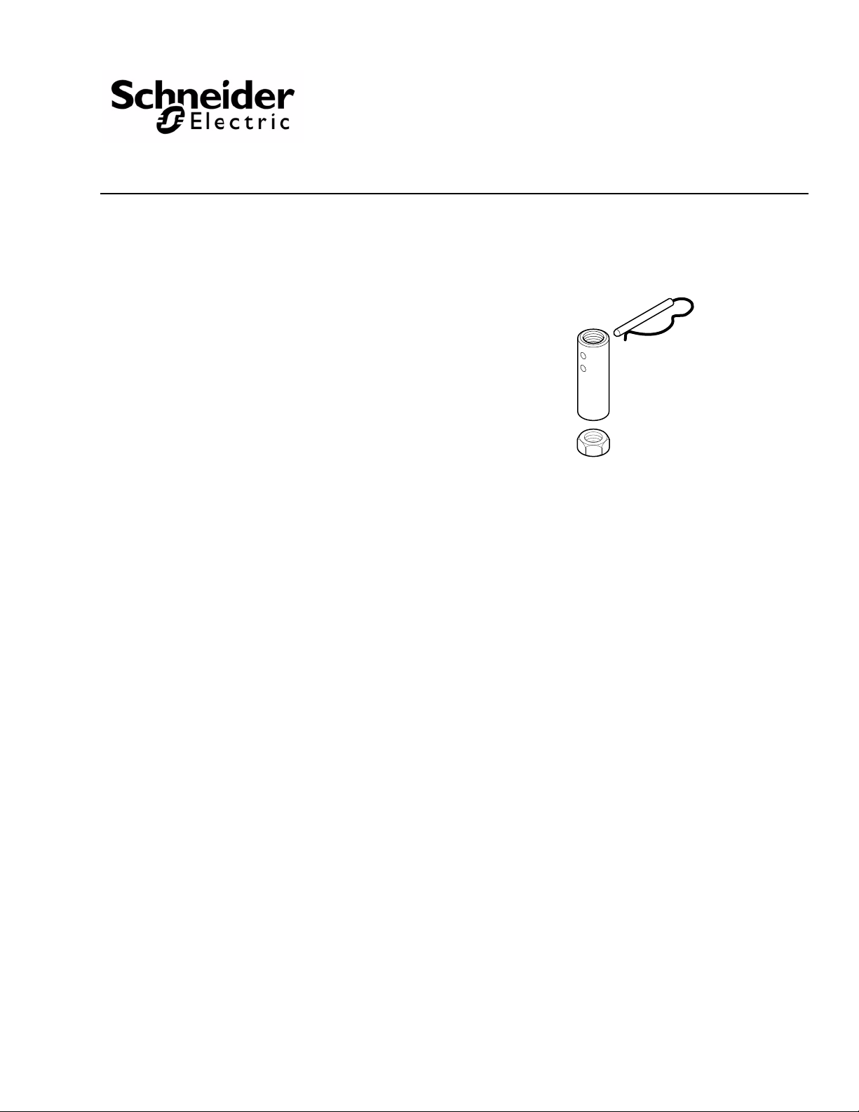
Required Components
INSTALLATION
Inspection
Requirements
Location: NEMA Type 1.
Actuator Mounting: In any upright position with actuator above the centerline of the valve
body.
The actuators and the valves must be purchased separately.
Inspect the package for damage. If damaged, notify the appropriate carrier immediately. If undamaged, open the package and inspect the device for obvious damage. Return any damaged products.
• Tools (not provided):
Appropriate wrenches for stem extensions, locknuts, and mounting bolts
• Training:
Installer must be a qualified, experienced technician
• Disconnect the air supply before installation, to prevent equipment damage.
• Make all connections in accordance with the piping diagram, and national and local
codes.
• Do not exceed the ratings of the device(s).
• Do not install the actuator below the center line of the valve. For steam applications only,
mount the actuator above the valve body at 45° from vertical.
• Avoid locations where excessive moisture, corrosive fumes, or vibration is present.
Mounting
When mounting an actuator onto a valve, using the AV-420 linkage, be sure the installation conforms to the following, as applicable:
1. Install all two-way valves so that they close against the flow. An arrow on the valve body or tag indicates proper flow direction.
2. Always install three-way mixing valves with two inlets and one outlet.
3. Always install three-way diverting valves with one inlet and two outlets.
4. Allow sufficient room above the actuator valve assembly for removal and reattachment of the actuator to the installed valve.
5. When selecting a location, allow sufficient room for accessories and for service of the product.
6. The valve actuator is generally mounted in an upright position, above the center line of the valve body. Do not mount the valve actuator below the center line of the valve.
7. The actuator may be swiveled, on a valve, to align the air conne ction with the control piping.
8. The actuator can be removed from the valve without disturbing the spring setting.
9. For steam applications only, position the valve body so the valve stem and actuator are at least at 45° from the vertical.
10. Maintain proper flow direction when installing all globe and radiator-type valves. Flow direction is indicated by an arrow on the valve body or by information on the attached tag.
11. Actuators can be mounted in any upright position above the centerline of a valve body.
2 © Copyright 2010 Schneider Electric All Rights Reserved. F-23325-5
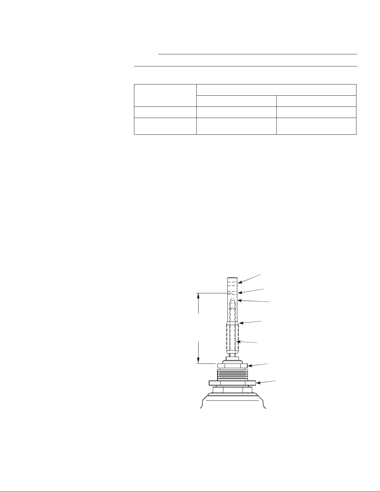
Assembly Instructions
N O T E
"X"
Stem Height
Dimension
(See Table-1)
Upper Hole
Lower Hole
Stem Extension
Locknut
Valve Stem
(Full Threads)
Valve Mounting Nut
Style A Valve Body
Packing Nut
The AV -420 linkage is required to assemble all MK-4800 series actuators to VB-9XXX series valve bodies. To install these parts, proceed as follows:
Refer to Table-1 to maintain the proper stem height during assembly.
Table-1 Valve Stem Height Dimensions.
Valve Assembly
2-Way Normally Open 2-5/8" (67 mm) Stem Down 3-3/4" (95 mm) Stem Down
2-Way Normally Closed
and 3-Way
Style A Valve Bodies Style B Valve Bodies
3-9/16" (91 mm) Stem Up 4-11/16" (119 mm) Stem Up
Stem Height Dimension ("X")
2-Way Normally Open Valves (Stem Down to Close)
Refer to Figure-1, Figure-2, Figure-3, Figure-4, Figure-5.
1. Push the valve stem down until the plug is seated.
2. Thread the locknut onto the valve stem.
3. See Figure-1 and Figure-2 to identify the valve as a Style A or Style B valve body , then proceed as follows:
a. On Style A valves, thread the stem extension onto the valve stem so that the height
of the center of the stem extension’s lower pin hole is 2-5/8" (67 mm) from the top of
the packing nut.
b. On Style B valves, thread the stem extension onto the valve stem so that the height
of the center of the stem extension’s upper pin hole is 3-3/4" (95 mm) from the top
of the machined bonnet ledge.
4. Lock the stem extension in position with the locknut.
5. On Style B valves only, thread the valve bonnet nut to the bottom of the valve bonnet.
F-23325-5 © Copyright 2010 Schneider Electric All Rights Reserved. 3
Figure-1 Adjust Stem Extension for Style A Valve Bodies.

"X"
Stem Height
Dimension
(See Table-1)
Upper Hole
Lower Hole
Stem Extension
Locknut
Valve Stem
(Full Threads)
Valve Bonnet Nut
Style B Valve Body
Valve Bonnet
Stem Extension
Piston Connector Hole
Stem Extension
Connector Hole
1/16" (1.5 mm)
Approximate Offset
Figure-2 Adjust Stem Extension for Style B Valve Bodies.
6. See Figure-1 and Figure-2 to identify the valve as a Style A or Style B valve body, then proceed as follows:
a. On Style A valves, thread the actuator onto the valve mounting nut. Rotate the actu-
ator, as necessary , so that the air connection fitting is in the desired position. Tighten
the valve mounting nut to secure the actuator in position.
b. On Style B valves, thread the actuator onto the valve bonnet until it bottoms. Back
off the actuator from the valve body at least one turn, counterclockwise, so that the
air connection fitting is in the desired position. Tighten the bonnet nut against the
actuator, to secure the actuator in position.
7. Rotate the stem extension, as necessary, to align the stem extension connector hole and the actuator piston connector hole (see Figure-4).
8. Pressurize the actuator to 20 psig (138 kPa ) and check the relative positions of the connector holes in the actuator piston and stem extension.The actuator piston connector
hole should be 1/16" to 1/8" (1.5 to 3 mm) below the stem extension connector hole, to
assure proper close-off (see
Figure-3). If the connector hole offset is not met, adjust the
position of the stem extension as follows:
a. Remove the ac tuator.
b. Loosen the locknut.
c. Adjust the stem extension to the desired position.
d. Re-tighten the locknut.
9. Reduce the pressure to the actuator until the connector holes in the actuator piston and
stem extension are aligned (see
Figure-4).
10. Insert the connector pin into the aligned connector holes.
4 © Copyright 2010 Schneider Electric All Rights Reserved. F-23325-5
Figure-3 Piston/Extension Hole Alignment for Normally Open 2-Way Valves with 20 psig

(138 kPa) Applied.
Stem Extension
Piston Shaft
Connecting Pin
(Use appropriate tool)
Figure-4 Installing the Connector Pin.
2-Way Normally Closed Valves (Stem Up to Close) and 3-Way Valves
1. Pull the valve stem up until the plug is seated.
2. Thread the locknut onto the valve stem.
3. See Figure-1 and Figure-2 to identify the valve as a Style A or Style B valve body , then proceed as follows:
a. On Style A valves, thread the stem extension onto the valve stem so that the height
of the center of the stem extension’s lower pin hole is 3-9/16" (91 mm) from the top
of the packing nut.
b. On Style B valves, thread the stem extension onto the valve stem so that the height
of the center of the stem extension’s upper pin hole is 4-11/16" (119 mm) from the
top of the machined bonnet ledge.
4. Lock the stem extension in position with the locknut.
5. On Style B valves only, thread the valve bonnet nut to the bottom of the valve bonnet.
6. See Figure-1 and Figure-2 to identify the valve as a Style A or Style B valve body , then proceed as follows:
a. On Style A valves, thread the actuator onto the valve mounting nut. Rotate the actu-
ator, as necessary , so that the air connection fitting is in the desired position. Tighten
the valve mounting nut to secure the actuator in position.
b. On Style B valves, thread the actuator onto the valve bonnet until the connector
holes in the actuator piston and stem extension are aligned. Be sure that the valve
stem is still up and the plug is seated. Back off the actuator from the valve body at
least one turn, counterclockwise, so that the air connection fitting is in the desired
position. Tighten the bonnet nut against the actuator, to secure the actuator in posi
tion.
-
F-23325-5 © Copyright 2010 Schneider Electric All Rights Reserved. 5

Figure-5 Typical Pneumatic Valve Assemblies Using MK-4800 Series Valve Actuator.
N O T E
Valve Assembly with Style A V alve Body Valve Assembly with Style B V alve Body
Stem Extension
Piston Connector Hole
Stem Extension
Connector Hole
1/16" (1.5 mm)
Approximate Offset
7. Rotate the stem extension, as necessary, to align the connector holes in the stem extension and actuator piston (see Figure-4).
8. The actuator piston connector hole should be 1/16" to 1/8" (1.5 to 3 mm) above the
stem extension connector hole, to assure proper close-off (see Figure-6). If the connector hole offset is not met, adjust the position of the stem extension as follows:
a. Remove the ac tuator.
b. Loosen the locknut.
c. Adjust the stem extension to the desired position.
d. Re-tighten the locknut.
Figure-6 Piston/Extension Hole Alignment for 3-Way Valves and Normally Closed 2-Way
Valves.
9. Apply sufficient air pressure to the actuator so that the connector holes in the actuator
piston and stem extension are aligned (see
Figure-4).
10. Insert the connector pin into the aligned connector holes.
Disassembly Instructions
6 © Copyright 2010 Schneider Electric All Rights Reserved. F-23325-5
Actuator Removal from Valve Body
1. Remove the connecting pin to release the valve stem linkage from the actuator piston.
T o remove the connector pin, it may be necessary to relieve any binding by stroking the actuator slightly with partial pressure.

MAINTENANCE
FIELD REPAIR
2. Disconnect the control air line from the actuat or.
3. For Style A valve bodies only, loosen the valve mounting nut (see Figure-1).
4. For Style B valve bodies only, loosen the valve bonnet nut (see Figure-2).
5. Lift the actuator until it clears the valve stem linkage.
The actuator linkage requires no maintenance.
Regular maintenance of the total system is recommended to assure sustained, optimum
performance.
Individual parts of the actuator linkage are not repairable. Replace an inoperative actuator linkage with a functional unit.
F-23325-5 © Copyright 2010 Schneider Electric All Rights Reserved. 7

On October 1st, 2009, TAC became the Buildings business of its parent company Schneider Electric. This document reflects the visual identity of Schneider Electric,
however there remains references to TAC as a corporate brand in the body copy. As each document is updated, the body copy will be changed to reflect approp riate
corpo r at e br a nd ch a nges.
Copyright 2010, Schneider Electric
All brand names, trademarks and registered
trademarks are the property of their respective
owners. Information contained within this
document is subject to change without notice.
F-23325-5
 Loading...