

Page 1

Advantys STB
INTERBUS Basic
Network Interface Module
Applications Guide
890USE19600 Version 1.0
31005789 00
31005789 00
Page 2

2
Page 3

Table of Contents
Safety Information . . . . . . . . . . . . . . . . . . . . . . . . . . . . . . . . . . . .5
About the Book. . . . . . . . . . . . . . . . . . . . . . . . . . . . . . . . . . . . . . .7
Chapter 1 Introduction. . . . . . . . . . . . . . . . . . . . . . . . . . . . . . . . . . . . . . . . . .9
What Is Advantys STB? . . . . . . . . . . . . . . . . . . . . . . . . . . . . . . . . . . . . . . . . . . . 10
What Is a Network Interface Module?. . . . . . . . . . . . . . . . . . . . . . . . . . . . . . . . . 11
About INTERBUS . . . . . . . . . . . . . . . . . . . . . . . . . . . . . . . . . . . . . . . . . . . . . . . . 13
Chapter 2 The STB NIB 1010 Basic NIM Module . . . . . . . . . . . . . . . . . . . .17
External Features of the STB NIB 1010 NIM . . . . . . . . . . . . . . . . . . . . . . . . . . . 18
STB NIB 1010 Fieldbus Interface . . . . . . . . . . . . . . . . . . . . . . . . . . . . . . . . . . . . 20
LED Physical Description . . . . . . . . . . . . . . . . . . . . . . . . . . . . . . . . . . . . . . . . . . 22
Power Supply Interface. . . . . . . . . . . . . . . . . . . . . . . . . . . . . . . . . . . . . . . . . . . . 24
Logic Power. . . . . . . . . . . . . . . . . . . . . . . . . . . . . . . . . . . . . . . . . . . . . . . . . . . . . 26
Selecting a Source Power Supply for the Island’s Logic Power Bus. . . . . . . . . . 27
STB NIB 1010 Module Specifications. . . . . . . . . . . . . . . . . . . . . . . . . . . . . . . . . 28
Chapter 3 Configuring the Island Bus . . . . . . . . . . . . . . . . . . . . . . . . . . . .29
Auto-Addressing . . . . . . . . . . . . . . . . . . . . . . . . . . . . . . . . . . . . . . . . . . . . . . . . . 30
Auto-Configuration . . . . . . . . . . . . . . . . . . . . . . . . . . . . . . . . . . . . . . . . . . . . . . . 32
The RST Button. . . . . . . . . . . . . . . . . . . . . . . . . . . . . . . . . . . . . . . . . . . . . . . . . . 33
Island Fallback Scenarios. . . . . . . . . . . . . . . . . . . . . . . . . . . . . . . . . . . . . . . . . . 34
Chapter 4 Fieldbus Communications Support . . . . . . . . . . . . . . . . . . . . .35
The INTERBUS ID Code. . . . . . . . . . . . . . . . . . . . . . . . . . . . . . . . . . . . . . . . . . . 36
Data Exchange . . . . . . . . . . . . . . . . . . . . . . . . . . . . . . . . . . . . . . . . . . . . . . . . . . 38
3
Page 4

Chapter 5 Application Example . . . . . . . . . . . . . . . . . . . . . . . . . . . . . . . . . 41
Sample Island Assembly . . . . . . . . . . . . . . . . . . . . . . . . . . . . . . . . . . . . . . . . . . . 42
Network Configuration Considerations . . . . . . . . . . . . . . . . . . . . . . . . . . . . . . . . 44
Using SyCon to Configure an STB Island on INTERBUS . . . . . . . . . . . . . . . . . . 46
Using CMD to Configure an STB Island on INTERBUS . . . . . . . . . . . . . . . . . . . 50
Glossary . . . . . . . . . . . . . . . . . . . . . . . . . . . . . . . . . . . . . . . . . . . . . . .53
Index . . . . . . . . . . . . . . . . . . . . . . . . . . . . . . . . . . . . . . . . . . . . . . .69
4
Page 5
Safety Information
§
Important Information
NOTICE Read these instructi ons carefully , and look a t the equipm ent to become fa miliar wi th
the device before trying to install, operate, or maintain it. The following special
messages may appear th roug hout thi s docu menta tion or on the equi pment to warn
of potential hazards or to call attention to information that clarifies or simplifies a
procedure.
The addition of this symb ol to a Da nger or Warning safety label ind icat es
that an electrical hazard exists, which will result in personal injury if the
instructions are not foll owed.
This is the safety alert symbol. It is used to alert you to potential personal
injury hazards. Obey all safety messages that follow this symbol to avoid
possible injury or death.
DANGER
DANGER indicates an imminently hazardous situation, which, if not avoided, will
result in death, serious in ju ry , or equipment damage.
WARNING
WARNING indicates a potentially hazardous situation, which, if not avoided, can result
in death, serious injury , or equipment damage.
CAUTION
CAUTION indicates a potentially hazardous situation, which, if not avoided, can result
in injury or equipment d am age.
890USE19600 April 2004 5
Page 6

Safety Information
PLEASE NOTE Electrical equipment should be serviced only by qualified personnel.
No responsibility is assumed by Sch neider Electric for any consequence s arising out
of the use of this material. This document is not intended as an instruction manual
for untrained persons.
© 2004 Schneider Electric. All Rights Reserved.
6
890USE19600 April 2004
Page 7

About the Book
At a Glance
Document Scope This guide describes the specific functionality of the STB NIB1010, the Advantys
STB basic network interface module to an INTERBUS network. To assist you with
setting up your Advantys STB island on an INTERBUS network, extensive, realworld INTERBUS a pplication exampl es are included . These instruc tions assume the
reader has a working familiarity with the INTERBUS fieldbus protocol.
This guide includes the following information about the STB NIB 1010:
l
role in an INTERBUS network
l
role as the gateway to Advantys STB island
l
external and internal interfaces
l
flash memory
l
integrated power supply
l
auto-configuration
l
island bus scanner functionality
l
data exchange between the island and the master
l
diagnostic messages
l
specifications
Validity Note The data and illustratio ns found in th is book are no t binding. We reserve the rig ht to
modify our products in l ine with ou r policy of continuous prod uct dev el opm en t. The
information in this document is subject to change without notice and should not be
construed as a commitment by Schneider Electric.
Related
Documents
890USE19600 April 2004 7
Title of Documentation Reference Number
The Advantys STB System Planning and Installation Guide 890USE17100
The Advantys STB Hardware Components Reference Guide 890USE17200
Page 8

About the Book
Product Related
Warnings
Schneider Electric assumes no res po ns ibi lit y for an y errors that may appear in this
document. If you have any suggestions for improvements or amendments or have
found errors in this publication, please notify us.
No part of this document may be reproduced in any form or by any means, electron ic
or mechanical, including photocopying, without express written permission of
Schneider Electric.
All pertinent state, regional, and local safety regulations must be observed when
installing and using this product. For reasons of safety and to assure compliance
with documented system data, only the manufacturer should perform repairs to
components.
When controllers are used for applications with technical safety requirements,
please follow the relevant instructions.
Failure to use Schneider Electric software or approved software with our hard ware
products may result in improper operating results.
Failure to observe this product related warning can result in injury or equipment
damage.
User Comments We welcome your comments about this document. You can reach us by e-mail at
TECHCOMM@modicon.com
8
890USE19600 April 2004
Page 9

Introduction
1
At a Glance
Summary This chapter describes the Advantys STBNIB 1010 basic INTERBUS network
interface module and its role in making the island a node on an INTERBUS open
fieldbus network.
What’s in this
Chapter?
This chapter contains the following topics:
Topic Page
What Is Advantys STB? 10
What Is a Network Interface Module? 11
About INTERBUS 13
890USE19600 April 2004 9
Page 10

Introduction
What Is Advantys STB?
Introduction Advantys STB is an assembly of distributed I/O, power, and other modules that
function together as an island node on an open fieldbus network. Advantys STB
delivers a highly modular and versatile slice I/O solution for the manufacturing
industry, with a migration path to the process industry.
Island Bus I/O A basic Advantys STB i sland c an s upport u p to 12 Ad vantys STB I/O modules. The
only I/O devices that may be used in the basic segm ent are Advantys STB modul es;
preferred modules, standard CANopen devices and Advantys STB extension
modules are not supported.
The Basic
Segment
STB I/O modules may be interconnected in a group called the basic segment. The
basic NIM is the first module in this segment. The basic segment must contain at
least one AdvantysSTB I/O module and can support as many as 12 addressable
Advantys STB modules, drawing a current load of up to 1.2 A. The segment must
also contain one or mo re PDMs, which d istribute field pow er to the I/O module s. The
basic segment must be terminated by a 120Ω termination plate, which ships with
the NIM.
10
890USE19600 April 2004
Page 11

Introduction
What Is a Network Interface Module?
Purpose An island of STB I/O modules requires a network interface module (NIM) in the
leftmost location of the basic island. Physically , the NIM is the first (leftmost) mod ule
on the island bus. Functionally, it is the gateway to the island bus—all
communications to and from the island bus pass through the N IM. The NIM also h as
an integrated power supply that provides logic power to the island modules.
The Fieldbus
Network
An island bus is a node of dis tribute d I/O o n an op en f ieldbu s netwo rk, a nd the NIM
is the island’s interface to that network. The NIM supports data transfers over the
fieldbus network between the islan d and the fie ldbus master.
The physical design of the NIM makes it compatible with both an Advantys STB
island and your specific fieldbus master. Whereas the fieldbus connector on each
NIM type may differ, the loc ation on the module front panel is essen tially the same .
Other NIM conne ctors, such as the pow er s up ply i nte rfac e, a re identical for all N IM
types.
Communications
Roles The NIM manages the exchange of input and output data between the island and
the fieldbus master. Input data, st ore d i n nat ive i sl and bus format, is co nv erte d to a
fieldbus-specific format that can be read by the fiel dbus mas ter. Outpu t data writt en
to the NIM by the m aster is sent acro ss the i sland bu s to upd ate the ou tput modu les
and is automatically reformatted.
Integrated Power
Supply
The NIM’s built-in 24-to-5 VDC power supply provides logic power to the I/O
modules on the basic segment of the island bus. The power supply requires a
24 VDC external power source. It converts the 24 VDC to 5 V of logic power,
providing 1.2 A of current to the island. Individual STB I/O modules in an island
segment generally draw a current load of between 50 and 90 mA. (Consult the
Advantys STB Hardware Components Reference Guide [890 USE 172] for a
particular module’s specifications.)
A basic NIM supports up to 12 Advantys STB I/O modules.
890USE19600 April 2004 11
Page 12
Introduction
Structural
Overview
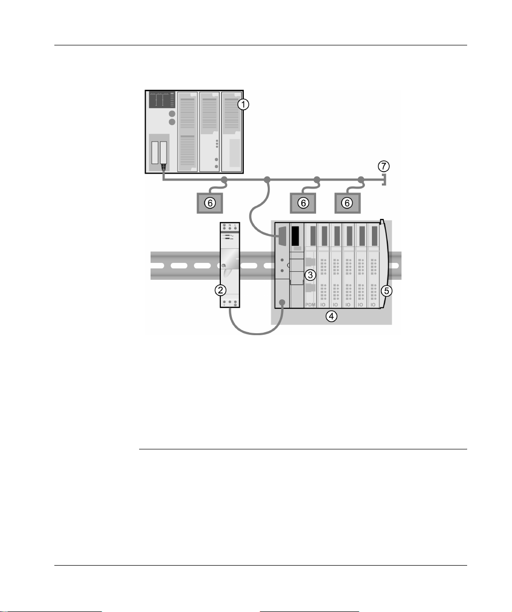
The following figure illustrates the multiple roles of the NIM. The figure provides a
network view and a physical representation of the island bus:
1 fieldbus master
2 external 24 VDC power supply, the source for logic power on the island
3 power distribution module (PDM)
4 island node
5 island bus terminator plate
6 other nodes on the fieldbus network
7 fieldbus network terminator (if required)
12
890USE19600 April 2004
Page 13
Introduction
About INTERBUS
Introduction IN TERBUS imple ments a maste r/slave net work model. It c an communic ate with up
to 512 nodes over a dist anc e o f 12.8 km , an d ca n read 1024 inputs and wri t e 10 24
outputs in 4 ms.
Each network slave has an in connector for receiving data a nd an out connector for
transmitting data on the ring. The last device automatically closes and terminates
the network ring; sometimes this last device has no out connector.
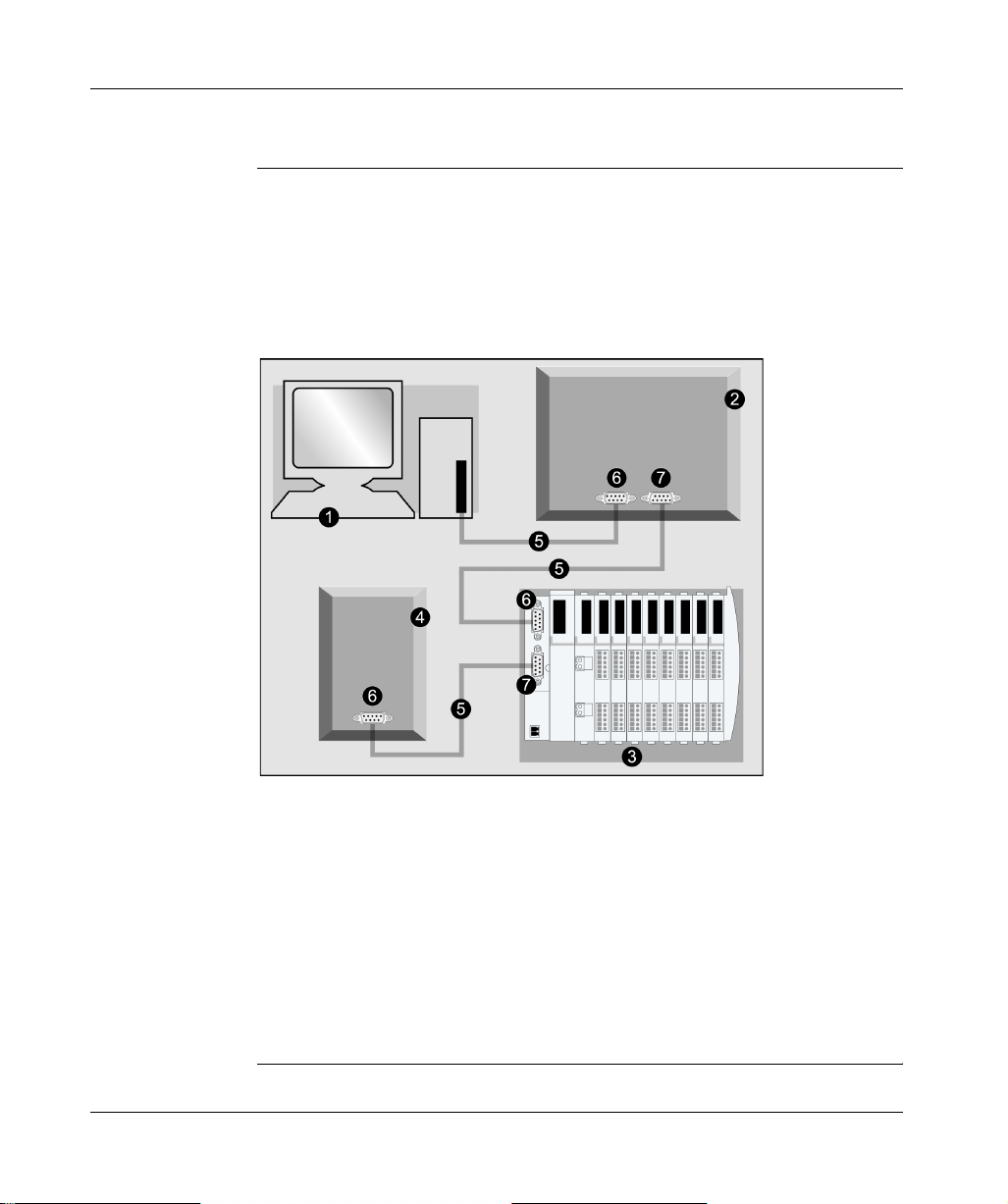
Components of a simplified INTERBUS network are shown below:
1 PC/PLC
2 slave device
3 Advantys STB island with INTERBUS NIM at the head
4 slave device
5 INTERBUS network cable
6 in connection (receive)
7 out connection (transmit)
INTERBUS Club is the supporting trade association that creates specifications for
INTERBUS networks and devices. For more on INTERBUS specifications and
mechanisms, refer to www.interbusclub .co m.
890USE19600 April 2004 13
Page 14

Introduction
Physical Layer The physical layer contains a single twisted pair of shielded wires. The
STB NIB 1010 INTERBUS implements the SUPI 3 (serial universal peripheral
interface) ASIC from Phoenix Contact.
Network
Topology
Transmission
Media
The INTERBUS network observes a master/slave model with active ring topology,
having all device s integrated in a closed tran smission path. There are thre e types of
bus structures in the ring:
l
remote bus—The AdvantysSTB island (with an STB NIB 1010 INTER BU S NIM
at the head) connects to this section. Remote bus characteristics include:
l
12.8 km (maximum) network length
l
512 possible connections
l
400 m (maximum) between dev ic es
l
256 devices (maximum)
l
local bus (not supported)—The local bus ring is used to conne ct I/O d evic es in a
remote substation enclosure. Local bus characteristics include:
l
8 devices (maximum)
l
1.5 m (maximum) between de vices
l
10 m (maximum) network length
l
800 mA (maximum) current
l
sensor loop—The sensor loop is connected directly to sensors and actuators
without the use of bridge routers. Sensor loop characteristics include:
l
1 unshielded pair (+24 V)
l
32 devices (maximum)
l
10 m (maximum) network length
Note: An Adv antys STB islan d with an INTERBUS NIM head can be implemente d
only as a remote bus node.
While it is possible to connect INTERBUS devices with a variety of media (fiber
optics, SMG, etc.), the STB NIB 1010 NIM only supports networks that are
connected with twisted pair copper wiring (RS-485). Network connectors (in and out)
are 9-pin SUB-D types. The TDMA transmission method is implemented for
transmission rates of 500 kbits/s.
14
890USE19600 April 2004
Page 15

Introduction
Node
Addressing
The INTERBUS master device is self-configuring because INTERBUS slave
devices are auto-addressed according to their sequence in a serial ring structure.
The master identif ies read/write da ta in terms of a node’s relati ve position i n the ring,
not by a fixed addres s. The sequ ential locat ion of slav es corresponds to the order of
input and output data in the master's buffer.
The ring structure uses a distributed shift register. In a single bus cycle, data from
the master to the slaves (and from the sla ves to the master) is transferred. The cy cle
ends when the loo p back word is returned to the master. Ea ch no de is a c omponen t
on the shift register ring on which data is circulated.
The NIM’s EDS For a particular device to be recog nized on you r netwo rk, a corres pondi ng EDS file
must be exported to your master device. Thi s ASCII file contains informat ion abo ut
a device’s:
l
identity—the node’s cl assificati on is prese nted in term s of the manu facturer co de
l
data size—the master’s input buffer must account for the amount of data
expected from the device
NIM Limitations The STB NIB 1010 INTERBUS basic NIM supports up to 16 words of INTERBUS
cyclic data. It does not support the parameter communication protocol (PCP).
890USE19600 April 2004 15
Page 16

Introduction
16
890USE19600 April 2004
Page 17

The STB NIB 1010 Basic NIM Module
2
At a Glance
Introduction Thi s chapter des cribes the external featu res, conne ctions, p ower requirem ents and
product specifications of the basic INTERBUS NIM.
What’s in this
Chapter?
This chapter contains the following topics:
Topic Page
External Features of the STB NIB 1010 NIM 18
STB NIB 1010 Fieldbus Interface 20
LED Physical Description 22
Power Supply Interface 24
Logic Power 26
Selecting a Source Power Supply for the Island’s Logic Power Bus 27
STB NIB 1010 Module Specifications 28
890USE19600 April 2004 17
Page 18
The STB NIB 1010 Basic NIM Module
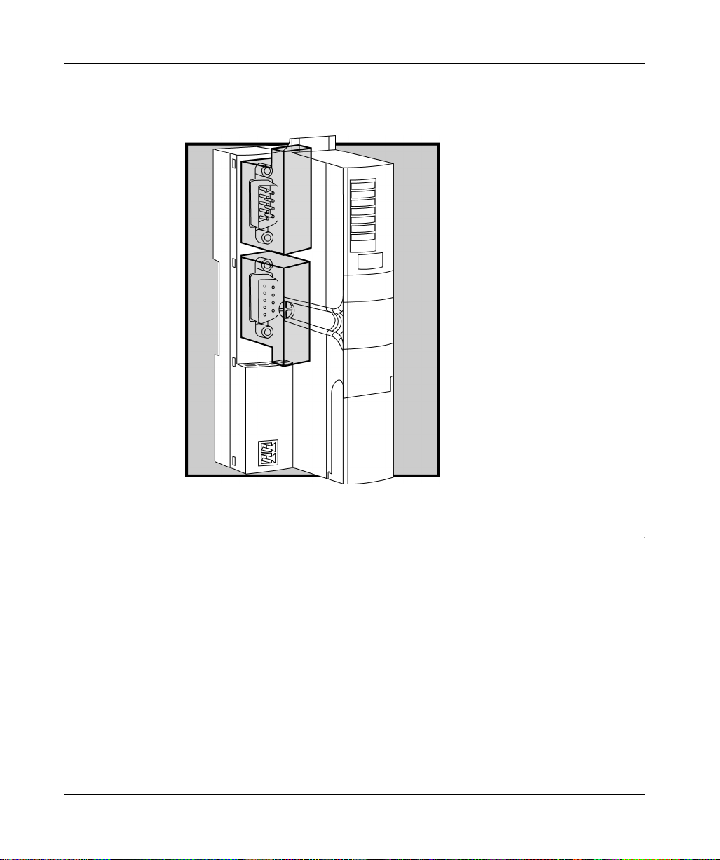
External Features of the STB NIB 1010 NIM
Hardware
Features
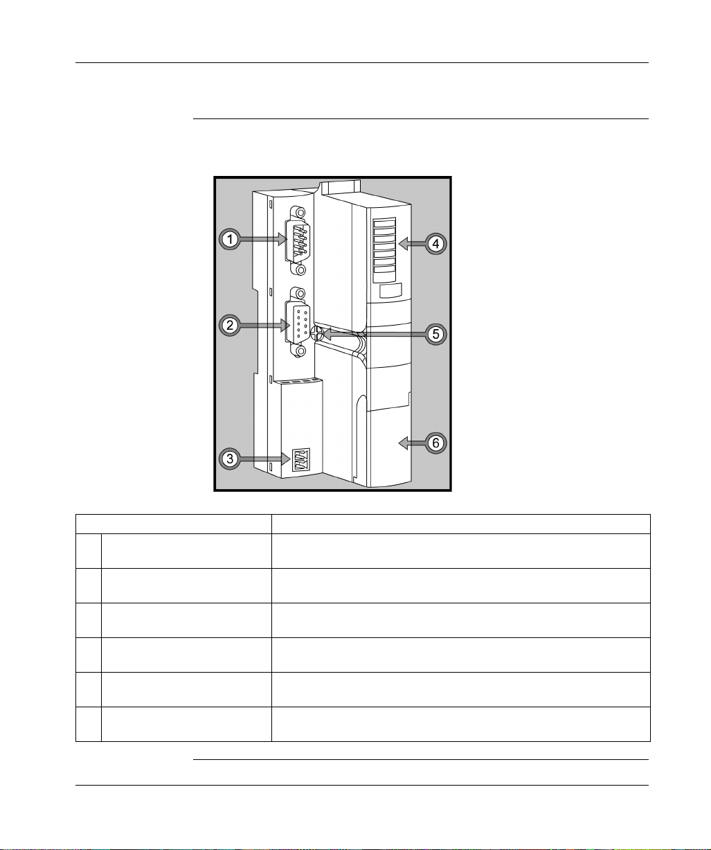
The physical features critical to STB NIB 1010 INTERBUS NIM operations are
called out in the illustration below:
Feature Function
1 fieldbus interface (in) Nine-pin SUB-D (male) connector used for the incoming INTERBUS fieldbus
network cable.
2 fieldbus interface (out) Nine-pin SUB-D (female) connector used for the outgoing INTERBUS
fieldbus network cable.
3 power supply interface A two-receptacle connector for connecting an external 24 VDC power supply
to the NIM.
4 LED array Colored LEDs that use various patterns to visually indicate the operational
status of the island bus.
5 release screw A mechanism used to remove the NIM from the DIN rail. (See the Advantys
STB System Planning and Installation Guide for details.)
6 CFG port cover A hinged flap on the NIM’s front panel that covers the CFG interface and the
RST button. The CFG port is for firmware upgrades only.
18
890USE19600 April 2004
Page 19
The STB NIB 1010 Basic NIM Module
Housing Shape The L-shaped external housing of the NIM is designed to accommodate the
attachment of the in and out INTERBUS network connectors without raising the
depth profile of the island:
1 space reserved for the network connectors
2 NIM housing
890USE19600 April 2004 19
Page 20
The STB NIB 1010 Basic NIM Module
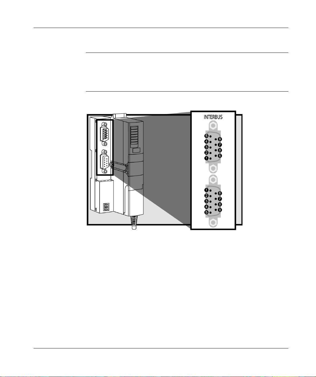
STB NIB 1010 Fieldbus Interface
Summary The fieldbus interface on the STB NIB 1010 is the point of connection between an
Advantys STB island bus a nd the INTERBUS netw ork. Like every IN TERBUS node,
the NIM has two nine-pin SUB-D connectors for data reception (in) and transmission
(out). The connectors are located on the face of the NIM.
Fieldbus Port
Connections
The in and out fieldbus interfa ces are lo cated on the front of the INTERBU S NIM at
the top:
It is recommended th at you use 9 -pin SUB-D connec tors compliant with INTERBUS
Club or corresponding international standard.
The in connector is optically isolated. The signal level is according to EIA RS-485.
20
890USE19600 April 2004
Page 21

The pin-out for both the in (upper) and out (lower) connectors should be according
to the table below (pin numbers correspond to callouts in the figure above):
Pin Signal (in) Signal (out)
1DO1 DO2
2DI1 DI2
3 GND1 GND
4 unused unused
5 unused +5 V
6/DO1 /DO2
7/DI1 /DI2
8 unused unused
9 unused RBST (see note below)
Note: The RBST pin detect s the presen ce of a sub sequent node on the ring. In the
absence of this detection (or if the node has no out connector at all), the network
ring is closed.
The STB NIB 1010 Basic NIM Module
INTERBUS
Networking
Cable and
Connectors
The drop cable from the fie ldbus to the Adv antys STB INTE RBUS NIM (and t he one
from the NIM to th e nex t IN TERB US nod e) mu st have connectors t hat ob serve this
pin assignment scheme. INTERBUS networking cables are shielded, twisted-pair
electrical cables, compliant with INTERBUS standard DR-303-1. There should not
be an interruption to any wire in bus cables. Th is allows for a future specific ation for
use of reserved pins.
890USE19600 April 2004 21
Page 22
The STB NIB 1010 Basic NIM Module
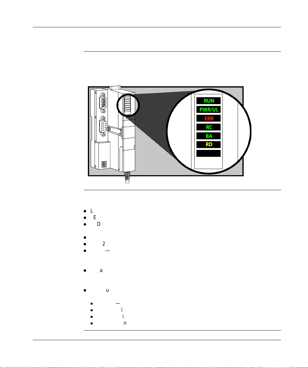
LED Physical Description
Overview The six LEDs implemented in the STB NIB 1010 INTERBUS NIM are visual
indications of the operat ing sta tus of th e isla nd bus o n an IN TERBUS net work . The
LED array is located at the top of the NIM front bezel.
General
Indications
22
The bottom three LEDs indicate the status of data exchange between the
INTERBUS fieldbus master and the Advantys island bus:
l
LED 4—RC (remote bus check)
l
LED 5—BA (bus active)
l
LED 6—RD (remote bus disa bled)
The top three LEDs indicate activity or events on the NIM:
l
LED 1—RUN
l
LED 2—PWR/UL
l
LED 3—ERR
The following tables describe the LED behavior in more detail. When you refer to
these tables, keep in mind:
l
It is assumed that th e PWR/UL LED is on co ntinuous ly, indic ating that the NIM i s
receiving adequ ate power. If the PWR/UL LED is off, l ogic power to t he NIM is off
or insufficient.
l
Individual blinks are approximately 200 m s. There is a 1-second i nterval between
blink sequences. For ex ample:
l
blinking—blinks steadily, alternating between 200 ms on and 200 ms off
l
blink 1—blinks once (200 ms), then 1 second off
l
blink 2—blinks twice (200 ms on, 200 ms off, 200 ms on), then 1 second off
l
blink n—blinks n (some number) times, then 1 second off
890USE19600 April 2004
Page 23

The STB NIB 1010 Basic NIM Module
INTERBUS Data
Exchange LEDs
The following table describes the indicated condition(s) and the colors and blink
patterns that the RC, BA and RD LEDs use to show normal operations and error
conditions for the NIM on an INTERBUS fieldbus.
Label Pattern Meaning
BA (green) on The module is transmitting data messages on the network.
off The module is not transmitting data messages on the network.
RC (green) on The island’s incoming bus is correctly connected, and the bus master device is not
off The island’s incoming bus is not correc tly conne cted, or the bus maste r devic e is sendin g
RD (yellow) on The island’s outgoing bus is disabled .
off The island’s outgoing bus is enabled.
NIM Activity
LEDs
RUN (green) ERR (red) Meaning
blink 2 blink 2 The island is powering up (self te st in pr o gr e s s) .
off off The island is initializing—it is not started.
blink 1 off The island has been put in the pre-oper ational state by the RST button—i t is
blinking (steady) off The NIM is auto-configuring the island bus—the bus is not started.
blink 3 off Initialization is complete, the island bus is configur ed, the configuration
off blink 6 The NIM detects no STB I/O modules on the island bus.
off blink 2 Assignment error—the NIM has detected a module assignment error; the
off blinking
on off The island bus is operational.
on blink 3 At least one module does not match—the island bus is operational with a
blink 4 off The island bus is stoppe d—no further communications with the island are
off on Fatal error—internal fai l ure.
The table that follows describes the island bus condition(s) communicated by the
LEDs, and the colors and blink patterns used to indicate each condition.
sending a bus reset signal.
a bus reset signal.
not started.
matches, and the bus is not started.
island bus is not started.
blink 5 Internal triggering protocol error.
(steady)
Fatal error. Because of the severity of the error, no further communications
with the island bus are possible an d th e NIM sto ps th e island . The f ollo wing
are fatal errors :
l
significant internal error
l
module-ID error
l
auto-addressing failur e
l
process image error
l
auto-configuration error
l
island bus management error
l
receive/transmit queue software overrun error
configuration mismatch.
possible.
890USE19600 April 2004 23
Page 24

The STB NIB 1010 Basic NIM Module
Power Supply Interface
Introduction The NIM’s built-in power supply requires 24 VDC from an external SELV-rated
power source. The con nection between the 24 VDC source and the Advantys STB
island is the two-receptacle connector illustrated below.
Physical
Description
Power from the external 24 VDC supply comes in to the NIM through a tworeceptacle connector located at the bottom left of the module:
1 receptacle 1—24 VDC
2 receptacle 2—common
24
890USE19600 April 2004
Page 25

Connectors Use either:
l
a screw type power connector, available in a kit of 10 (model STB XTS 1120)
l
a spring clamp power connector, available in a kit of 10 (model STB XTS 2120)
The following illustrati ons show two view s of each power con nector type. A fron t and
back view of the STBXTS 1120 screw type connector is shown on the left, and a
front and back view of the STB XTS 2120 spring clamp connector is shown on the
right:
1 STBXTS 1120 screw-type power connector
2 STBXTS 2120 spring clamp power connector
3 wire entry slot
4 screw clamp access
5 spring clamp actuation button
The STB NIB 1010 Basic NIM Module
Each entry slot accepts a wire in the range 0.14 to1.5 mm2 (28 to 16 AWG). Each
connector has a 3.8mm (0.15 in) pitch between the receptacles.
We recommend that you strip at least 9mm from the wire’s jacket to make the
connection.
890USE19600 April 2004 25
Page 26

The STB NIB 1010 Basic NIM Module
Logic Power
Introduction Log ic power is a 5VDC power signal on the island bus th at the I/O modu les require
for internal processing. The NIM has a built-in power supply that provides logic
power. The NIM sends the 5 V logic power signal across the island bus to support
the modules in the basic segment.
External Source
Power
Logic Power
Flow
Input from an external 24VDC power supply is needed as the sou rce power for the
NIM’s built-in power s upply. The NIM’s built-i n p ow er s up ply c onv erts the incoming
24 V to 5 V of logic power. The external supply must be rated safety extra low
voltage (SELV-rated).
CAUTION
IMPROPER GALVANIC ISOLATION
The power component s are not galvanical ly isolated. They a re intended
for use only in systems desig ned to provide SELV isolation betwee n the
supply inputs or outpu ts and the load devic es or system power bus . You
must use SELV-rated supplies to provide 24 VDC source power to the
island.
Failure to follow this precaution can result in injury or equipment
damage.
The figure below shows how the NIM’s integrated power supply generates logic
power and sends it across the basic segment:
5V
26
24 V
24 VDC
890USE19600 April 2004
Page 27

The STB NIB 1010 Basic NIM Module
Selecting a Source Power Supply for the Island’s Logic Power Bus
Logic Power
Requirements
Characteristics
of the External
Power Supply
Calculating the
Wattage
Requirement
An external 24 VDC power supply is needed as the source for logic power to the
island bus. The external power supply connects to the island’s NIM. This external
supply provides the 24 V input to the built-in 5 V power supply in the NIM.
The external power s upply needs to deliver 24VDC source power to the island . The
supply that you s elect c an have a low range limit of 19.2 VDC and a high range limit
of 30 VDC. The external suppl y must be rated safety extra l ow voltage (SELV-rated).
The SELV-rating means tha t SELV isolation is provided between the power suppl y’s
inputs and outputs, the power bus, and the devices connected to the island bus.
Under normal or single-fault conditions the voltage between any two accessible
parts, or between an acce ssible part and the protective earth (PE) termin al for Class
1 equipment, will not exceed a safe value (60 VDC max.).
CAUTION
IMPROPER GALVANIC ISOLATION
The power componen ts are not ga lvanica lly isol ated. They are intende d for use onl y
in systems designed to provide S ELV isol ation betwee n the supp ly inputs or outputs
and the load devices or system power bus. You must use SELV-rated supplies to
provide 24 VDC source power to the island.
Failure to follow this precaution can result in injury or equipment damage.
The external supply needs to provide 13W of power to the NIM.
Suggested
Devices
The external power supp ly is gen erally enclosed in the sa me c ab inet as the island.
Usually the external power supply is a DIN rail-mountable unit.
For installations that requi re 72 W or less from a 24 VDC source power supply, we
recommend a device such as the ABL7RE2403 Phaseo power supply from
Telemecanique, distri buted in the United Stat es by Square D. This s upply is DIN railmountable and has a form factor similar to that of the island modules.
If you have room in your c abi ne t and your 24 VDC power req uire ments are greater
than 72 W, summable power supply options such as Schneider’s Premium
TSX SUP 1011 (26 W), TSX SUP 1021 (53 W), TSX SUP 1051 (120 W), or
TSX SUP 1101 (2 40 W ) can be considere d. These modules a re als o availabl e from
Telemecanique and, in the United States, from Square D.
890USE19600 April 2004 27
Page 28

The STB NIB 1010 Basic NIM Module
STB NIB 1010 Module Specifications
Table of
Technical
Specifications
dimensions width 40.5 mm (1.59 in)
height 130 mm (5.12 in)
depth 70 mm (3.15 in)
interface connectors from INTERB US networ k nine-pin SUB-D connector (male)
to INTERBUS network nine-pin SUB-D connector (female)
RS-232 port for
configuration software or
HMI panel
to external 24 VDC power
supply
built-in power supply input voltage 24 VDC nominal
input power range 19.2 ... 30 VDC
input current 400 mA @ 24 VDC
output voltage to island
bus
output current rating 5 VDC @ 1.2 A
isolation no internal isolation (isolation must be provided by a SELV-rated
noise immunity (EMC) IEC 1131-2
addressable I/O modules supported 12 maximum
segments supported one
hot swapping no
standards INTERBUS conformance INTERB US Club (www.interbusc lub.com)
MTBF 200,000 hours GB (ground benign)
8-receptacle HE-13
2-receptacle
5 VDC @ 1.2 A
2% variation due to temperature drift, intolerance, or line
regulation
1% load regulation
<
50 mΩ output impedance up to 100 kHz
external 24 VDC source power supply)
28
890USE19600 April 2004
Page 29

Configuring the Island Bus
3
At a Glance
Introduction The information in this chapter describes the auto-addressing and auto-
configuration processes. This data is saved to Flash memory automatically.
What’s in this
Chapter?
This chapter contains the following topics:
Topic Page
Auto-Addressing 30
Auto-Configuration 32
The RST Button 33
Island Fallback Scenarios 34
890USE19600 April 2004 29
Page 30

Configuring the Island Bus
Auto-Addressing
Introduction Each time that the island is powered up or reset, the NIM automatically assigns a
unique island bus address to each module on the island that will engage in data
exchange. All Advantys STB I/O modules engage in data exchange.
About the Island
Bus Address
Addressable
Modules
An island bus address is a unique integer value in the range 0 through 127 that
identifies the physical location of each addressable module on the island. Address
127 is always the NIM’s address. Addresses 1 through 12 are available for
addressable Advantys STB modules. The remaining addresses are not used in a
basic island configuration.
During initialization, the NIM detects the order in which modules are installed and
addresses them sequentially from left to right, starting with the first addressable
module after the NIM. No user action is required.
Only the Advantys STB I/O modules in the basic segment require island bus
addresses.
Because they do not exchange data on the island bus, the following are not
addressed:
l
PDMs
l
empty bases
l
terminati on plate
30
890USE19600 April 2004
Page 31

Configuring the Island Bus
An Example For example, if you have an island bus with eight I/O modules:
1 NIM
2 STB PDT 3100 24 VDC power distribution module
3 STB DDI 3230 24 VDC two-channel digital input module
4 STB DDO 3200 24 VDC two-channel digital output module
5 STB DDI 3425 24 VDC four-channel digital input module
6 STB DDO 3415 24 VDC four-channel digital output module
7 STB DDI 3615 24 VDC six-channel digital input module
8 STB DDO 3605 24 VDC six-channel digital output module
9 STB AVI 1275 +/-10 VDC two-channel analog input module
10 STB AVO 1255 0 ... 10 VDC two-channel analog output module
11 STB XMP 1100 island bus termination plate
The NIM would auto-address it as follows. Note that the PDM and the termination
plate do not consume island bus addresses:
Module Physical Location Island Bus Address
NIM 1 127
STB PDT 3100 PDM 2 not addressed— does not exc hange data
STB DDI 3230 input 3 1
STB DDO 3200 output 4 2
STB DDI 3425 input 5 3
STB DDO 3415 output 6 4
STB DDI 3615 input 7 5
STB DDO 3605 output 8 6
STB AVI 1275 input 9 7
STB AVO 1255 output 10 8
890USE19600 April 2004 31
Page 32

Configuring the Island Bus
Auto-Configuration
Introduction All AdvantysSTB I/O modules are shipped with a set of predefine d paramete rs that
allow an island to be operational as soon as it is initialized. This ability of island
modules to operate with default parameters is known as auto-configuration. Once
an island bus has been installed, you can begin using it as a node on that network.
About AutoConfiguration
Auto-configuration occurs when:
l
You power up an island for the first time.
l
You push the RST button.
As part of the auto-configuration process, the NIM checks each module and
confirms that it has been properly connected to the island bus. The NIM stores the
default operating parameters for each module in Flash memory.
32
890USE19600 April 2004
Page 33

Configuring the Island Bus
The RST Button
Summary Use the RST function to reconfigure your island after you have added a new I/O
module to a previously auto-configured island. If a new I/O module is added to the
island, pressing the RS T button forces th e auto-configurat ion process. T he updated
island configurati on data is autom atically saved . RST works on ly after the isl and has
been successfully configured at least once.
Physical
Description
Engaging the
RST Button
The RST button is located immediately above the CFG port, and behind the same
hinged cover:
RST button
Holding down the RST button for two seconds or longer causes the island to auto
configure and the Flash memory to be overwritten.
To engage the RST button, use a small screwdriver with a flat blade no wider than
2.5 mm (.10 in). Do not use a sharp object that might damage the RST button or a
soft item such as a pencil that might break off and jam the button.
When you push the RST button for at least two seconds, the NIM reconfigures the
island bus as follows:
Stage Description
1 The NIM auto-addresses the I/O modules on the island and derives their
factory-default configuration values.
2 The NIM overwrites the current configuration in Flash memory with
configuration data that uses the factory-default values for the I/O modules.
3 It re-initializes the island bus and brings it into operational mode.
Note: Netw ork settin gs such as the fiel dbus bau d and the fi eldbus no de ID remain
unaffected.
890USE19600 April 2004 33
Page 34

Configuring the Island Bus
Island Fallback Scenarios
Introduction In the even t of a c ommuni cations failure o n the is land or between the is land and the
fieldbus, output data is put into a predefined fallback state so that the module’s
values are known when the system recov ers from the failure.
When you use a basic NIM, you cannot change the fallback parameters of any
modules in the segment. All output channels on the modules go to a predefined
fallback value of 0.
Fallback
Scenarios
Heartbeat
Message
There are several scenarios in which Advantys STB output modules go into their
fallback states:
l
loss of fieldbus communications—Communications with the fieldbus master are
lost.
l
loss of island bus communications—There is an internal island bus
communications error, ind icated by a mis sing h eartbeat message from e ither the
NIM or a module.
l
change of operating state—The NIM may command the island I/O modules to
switch from a running to a non-running (stopped or reset) state.
In all of these fallback scenarios, the NIM disables the heartbeat message.
Note: If a module fails, it needs to be replaced. The module may not go to its
fallback state.
The Advantys STB system relies on a heartbeat messag e to ensure the inte grity and
continuity of commun icati ons betwee n the NIM and the isla nd modu les. The health
of island modules and the overall integrity of the AdvantysSTB system are
monitored through the transmission and reception of these periodic island bus
messages.
Because island I/O modules are configured to monitor the NIM’s heartbeat
message, output modules will go into their fallback states if they do not receive a
heartbeat message from the NIM within the defined interval.
34
890USE19600 April 2004
Page 35

Fieldbus Communications Support
4
At a Glance
Introduction Thi s chapter desc ribes how t he INTERBUS mas ter sets up com munications w ith an
Advantys STB island and the network parameterization, configuration and
diagnostics services performed to configure the island as an INTERBUS node.
To communicate wi th an Advanty s STB isla nd, the INTER BUS maste r sends outp ut
data across its network to the STB NIB 1010 basic NIM. The NIM transfers this
output data across the island bus to the destination output modules. The NIM
collects input data from the island’s input modules and sends the data back to the
fieldbus master in a bi t-packed format.
What’s in this
Chapter?
890USE19600 April 2004 35
This chapter contains the following topics:
Topic Page
The INTERBUS ID Code 36
Data Exchange 38
Page 36

Fieldbus Communications Support
The INTERBUS ID Code
Introduction The ID cycle is part of the INTERBUS network’s initialization process. After
determining the length of its own data during network initialization, every network
device reports its functionality and byte length in the two-byte ID code. The
INTERBUS ID code is a 16-bit word that describes the data type, data length and
module type (digital/analog, input/output/mixed) of network devices.
The Low and
High Bytes
Data type is transmitted in the ID code’s low byte; data length and message
information are reported in the high byte:
1 data type (03h, 33h)
2 data length (0 to 16 words)
3 messages (for management functions)
Data Type The INTERBUS NIM recognizes one of two possible data types:
Data Type Signal Direction Signal Type
03h input/output digital
33h input/output analog or mixed
36
890USE19600 April 2004
Page 37

Fieldbus Communications Support
Data Length The following table shows the relationship between the actual data length of the
island and the length of the code on INTERBUS. The ac tu al da ta length (anywhere
from 0 to 16 words) represents the greater of the input or output data length.
Actual Length of Island Data INTERBUS Data Length Data Length Code (Hex)
up to 1 word* 1 word 1
2 words 2 words 2
3 words 3 words 3
4 words 4 words 4
5 words 5 words 5
6 words 6 words E
7 words 7 words F
8 words 8 words 6
9 words 9 words 7
10 words 10 words 15
11 to 12 words 12 words 16
13 to 14 words 14 words 17
15 to 16 words 16 words 12
17 to 24 words** 24 words 13
25 to 26 words** 26 words 11
* The status word is included in the data length, so the minimum allowable data length for an Advantys island is 2
words (data word + status word).
** The STB NIB 1010 INTERBUS NIM supports only up to 16 words in each direction (input/output).
890USE19600 April 2004 37
Page 38

Fieldbus Communications Support
Data Exchange
Introduction Process image data is exchanged between the STB NIB 1010 NIM and an
INTERBUS fieldbus master in a bit-packed format.
Note: In t his discussi on, data and words des cribed as input and output are defined
relative to the master. For example, the master receives input data and transmits
output data.
Data and Status
Objects
Data exchange between th e island a nd the INTERBU S master in volves three types
of objects:
l
data objects—operating values the INTERBUS master either reads from the input
modules or writes to the output modules
l
status objects—module health records sent by I/O modules and read by the
INTERBUS master
l
echo output data objects—sent by digital object modules to the INTERBUS
master; these obje cts are usual ly a copy of the data objec ts, but they ca n contain
useful informati on when a digital o utput poin t is con figured to handle th e result of
a reflex action
Standard Advantys STB I/O modules support all three of the above objects. Basic
Advantys STB I/O modules support only data objects, not status or echo objects.
The following table shows the relationship between different object types and
different module types. It also shows the size of the different objects:
Module Type Objects in the Input Data Image Objects in the Output Data Image
Objects Size Objects Size
digital input data 1 byte or less does not apply
1
status
digital output echo output data 1 byte or less data 1 byte or less
1
status
analog input channel 1 data 2 bytes does not apply
2
status
channel2 data 2 bytes does not ap ply
2
status
analog output channel 1
channel 2
1
Echo and status information is not available for every module. For example, basic I/O modules do not report this information. Refer
to The Advantys STB Hardware Components Reference Guide (890 USE 172 00) for details.
2
Status information is not available for every analog module. For example, basic analog modules do not report status. Refer to The
Advantys STB Hardware Components Reference Guide (890 USE 172 00) for details.
status
status
2
2
1 byte or less does not apply
1 byte or less does not apply
1 byte does not apply
1 byte does not apply
1 byte data 2 bytes
1 byte data 2 bytes
38
890USE19600 April 2004
Page 39

Fieldbus Communications Support
The Internal
Process Image
Word
Boundaries and
Bit Packing
Bit Packing
Rules
The STB NIB 1010’s process image contains memory areas (buffers) for the
temporary storage of input and output d ata. The internal process image is part of the
NIM’s island bus scanner area.
The island bus manages data exchange in both directions:
l
input data from the island bus—The island bus scanner operates continuously,
gathering data as well as status and confirmation bits and putting them into the
process image’s input buffer.
l
output data to the island bus—The island bus scanner handles output data and
places it in the process image’s out put buff er.
Input data and output data a re assembled in the order of the isl and bus I/O mo dules
(from left to right).
Every entry in the process image is in a multiple-word format. If modules on t he
island bus have input or output data entries that are not multiple words, the
corresponding word in the process image is moved to the next word boundary.
For example, a module with one bit of output data starts on a word bou nda ry in the
process image’s outp ut data buffer. Th e next process image entry starts on the ne xt
word boundary, thereby transmitting 15 unused bits of the module’s first word,
resulting in latency during data transmission on the fieldbus.
Bit packing allows bi ts of data on the fi eldbus from d ifferent digita l I/O modules to be
put together in a single byte, resulting in optimized bandwidth.
The STB NIB 1010 NIM observes the following rules for the bit packing of the
external process image:
l
The input and output process image sizes are limited to 16 words each.
l
The first word of the input process image contains NIM status information. The
first word of the output process image contains the NIM control word.
l
Bit packing follows the addressing order of the island bus I/O modules, from left
to right in the basic segment.
l
When the data object (or echo output data object) for a specific module is
available, it precedes the status object for that module.
l
Status objects and data objects for the same or different I/O module may be
packed in the same word if the size of the combined objects is 16 bits or less.
l
If the combination of objects requir es more than 16 bi ts, the objects wil l be placed
in separate contiguous bytes. A single object cannot be split over two
word boundaries.
l
For standard analog input modules, channel 1 data is followed immediately by
channel 1 status, then channel 2 data and channel 2 status.
890USE19600 April 2004 39
Page 40

Fieldbus Communications Support
Input and Output
Data Exchange
The application of the INTERBUS bit packing rules to the sample island assembly
results in four words of output data and five words of input data. The tables that
follow show how dig ital data is bit pac ked for optimiza tion, and how d ata, status, and
echo output data (from outputs) appear in the PLC as the same data type (digital
input data). In these tables, N refers to the island node number. That is, N1
represents the first addressable node (module) on the sample island bus, N2 the
second, and so forth.
Output Data
Exchange
Bit Number
Word 15 14 13 12 11 10 9 8 7 6 5 4 3 2 1 0
1 NIM control word
2 empty (set to 0) N6 output data N4 output data N2 output
3 N8 (channel 1) analog output data
4 N8 (channel 2) analog output data
Input Data
Exchange
The following table s hows ho w the four words in the sample i sland as sembly output
data process image are organized after applying the bit packing rules:
data
The following tabl e sho ws how the fi ve word s of the sam ple i sland asse mbly outpu t
data process image are org anized after applyin g the bit packing ru les. The first word
contains the NIM status.
Bit Number
Word 15 14 13 12 11 10 9 8 7 6 5 4 3 2 1 0
1 NIM status
2 empty (set to 0) N3 input data N2 output
status
3 empty (set to 0) N5 input data
4 N7 (channel 1) analog input data
5 N7 (channel 2) analog input data
N2 output
echo
N1 input
status
N1 input
data
40
890USE19600 April 2004
Page 41

Application Example
5
At a Glance
Introduction Thi s chap ter prese nts two ex amples fo r config uring th e Advant ysSTB island on an
INTERBUS network. Each ex am ple im ple me nts the s am e sam ple island assembly
with an Advantys STBNIB 1010 basic NIM.
What’s in this
Chapter?
This chapter contains the following topics:
Topic Page
Sample Island Assembly 42
Network Configuration Considerations 44
Using SyCon to Configure an STB Island on INTERBUS 46
Using CMD to Configure an STB Island on INTERBUS 50
890USE19600 April 2004 41
Page 42

Application Example
Sample Island Assembly
Introduction The configuration example(s) in this chapter use a particular Advantys STB island
assembly, described below. Your island assembly is independent of the network’s
master scanner because the island is represented by the NIM as a single node on
the fieldbus network.
Sample Island
Assembly
The sample I/O sy st em used in this chapt er’s ap pli ca tion example(s) imple me nts a
variety of analog and digital modules.
1 STB NIB 1010 INTERBUS NIM
2 STB PDT 3100 24 VDC PDM
3 STB DDI 3230 two-channel 24 VDC digital input module (2 bits of data, 2 bits of status)
4 STB DDO 3200 two-channel 24 VDC digital output module (2 bits of data, 2 bits of echo
output data, 2 bits of status)
5 STB DDI 3425 four-channel 24 VDC digital input module (4 bits of data, 4 bits of status)
6 STB DDO 3415 four-channel 24 VDC digital output module (4 bits of data, 4 bits of echo
output data, 4 bits of status)
7 STB DDI 3615 six-channel 24 VDC digital input module (6 bits of data, 6 bits of status)
8 STB DDO 3605 six-channel 24 VDC digital output module (6 bits of data, 6 bits of echo
output data, 6 bits of status)
9 STB AVI 1275 two-channel +/-10 VDC analog input module (16 bits of data [channel 1], 16
bits of data [channel 2], 8 bits of status [channel 1], 8 bits of status [channel 2])
10 STB AVO 1255 two-channel 0 ... 10 VDC analog output module (8 bits of status [channel
1], 8 bits of status [channel 2], 16 bits of data [channel 1], 16 bits of data [channel 2])
11 STB XMP 1100 termination plate
42
890USE19600 April 2004
Page 43

The I/O modules have the following island bus addresses:
I/O Model Module Type Island Bus Address
STB DDI 3230 two-channel digital input 1
STB DDO 3200 two-channel digital output 2
STB DDI 3425 four-channel digital input 3
STB DDO 3415 four-channel digital output 4
STB DDI 3615 six-channel digital input 5
STB DDO 3605 six-channel digital output 6
STB AVI 1275 two-channel analog input 7
STB AVO 1255 two-channel analog output 8
The NIM, the PDM, and the te rmination plate do not consume isl and bus addresses,
and they do not exchange data with the fieldbus master.
Application Example
890USE19600 April 2004 43
Page 44

Application Example
Network Configuration Considerations
Introduction This topic covers items to consider before you configure your INTERBUS network
for use with an AdvantysSTB island.
Connection
Figure
The following figure shows the connections between a master device and its slave
devices on an INTERBUS network:
1 PC/PLC
2 INTERBUS network cable (not supplied)
3 network node
4 Advantys STB sample island assembly
5 slave device (terminating)
44
Note: An Advantys STB island with an INTERBUS NIM can be implemented only
as a remote bus node.
890USE19600 April 2004
Page 45

Application Example
Before You
Begin
SyCon
Considerations
CMD
Considerations
Before attempting to use the application examples in this chapter, make sure:
l
your Advantys STB modules are assembled, ins talled, and pow ered accordin g to
your particular system, application, and network requirements
l
you know the inp ut and output p rocess data leng ths for your specifi c configuration
(the sample island assembly’s input length is 80 bits and the output length is 64
bits)
You should have a working fam iliarity with both the INTER BUS fieldbus protocol and
your configuration software, either SyCon or CMD.
Note: For specific information about your configuration software, consult the
manufacturer’s documentation included with the Hilscher (SyCon) or Phoenix
Contact (CMD) product.
You should have the EDS file an d corresponding bitmap fi les that were supplied w ith
the STB NIB 10 10 INTERBUS NIM (also available at www.schneiderauto-
mation.com), or you have created an EDS that is specific to the sample island
assembly with the Advantys or SyCon configuration software.
You should have t he Sch neide r devi ce da tabase , Schn eid er_Devi ce_D B, ava ilabl e
at www.schneiderautomation.com. It includes the Advantys STB catalog entry. If
you don’t have this database, you can create a configuration-specific device by
following the instructions for CMD configuration.
The sample islan d assembly’s input leng th is 80 bit s and the ou tput length i s 64 bits.
If you do not account for the entire data length of your island, process data will be
truncated or connection to the network will be impossible.
890USE19600 April 2004 45
Page 46

Application Example
Using SyCon to Configure an STB Island on INTERBUS
Introduction To add any master device and an Advantys STB island slave to your configuration
with SyCon:
Stage Description
1 Add a master to your network configuration.
2 A dd the NIM to your network configuration.
3 Create an EDS for the Advantys STB island.
4 S ave and download the configuration
Add a Master Use the following procedure to add an INTERBUS master to your configuration. In
this case, the Hilscher CIF3 0 PCMC IA c ard is use d. Th e ste ps are the s am e for all
master devices.
Step Action Comment
1 From SyCon’s Insert menu, select
Master.
2 Select CIF30-IBM from the Available
devices list and click Add.
3 Press OK. The CIF30-IBM appears in the SyCon
A list of INTERBUS masters appears in
the Insert Master dialogue box.
The CIF30-IBM appears in the Selected
devices list.
workspace.
46
890USE19600 April 2004
Page 47

Application Example
Add the NIM You mus t import the NIM’s EDS be fore you configure the island as a network devic e.
To add the NIM to the netw ork configuration:
Step Action Comment
1 From SyCon’s Insert menu, select
Remote Bus Device or the insert
remote device icon.
2 Decide where you want to insert the
NIM device.
3 Click in the appropriate blue circle. The Insert Remote Bus Device dialogue box
4 Select the NIM’s EDS from the
Available devices list and click Add.
5 Press OK. The island appears in the SyCon
The Advantys STB island can only be used
as a remote node on INTERBUS.
Blue circles in the workspace indicate
possible insertion points.
appears.
The EDS appears in the Selected devices
list. If not, follow the directions at Create an
EDS.
workspace.
Configuring in
the SyCon
Workspace
After you use the Add a Master and Add the NIM instructions to add the CIF30
master and INTERBUS NIM slave to your network configuration, a SyCon
workspace similar to this appears:
890USE19600 April 2004 47
Page 48

Application Example
Create an EDS You can create an EDS using SyCon's EDS Generator by following these
instructions:
Step Action Comment
1 From SyCon’s Tools menu, select
EDS Generator.
2 In the Created by text field, enter
the creator’s name.
3 In the Device text field, enter the
device name and manufacturer.
4 From SyCon’s Type pull-down
menu, select Remote Bus Device.
5 Specify the Process data direction
by selecting input/output.
6 Specify the analog Device class. The selection of analog supports the mixture of digital
7 Specify the Process data length by
selecting an input length of 10
octets, and an output length of 8
octets.
8 An Ident code should appear
under Device identification.
9 In the Configuration (Bitmap) text
field, select the desired .bmp file or
accept the defaults.
The EDS Generator dialogue box appears.
Use your own name.
The device will use the name you enter here when it
appears in the configuration workspace.
The Advantys STB island can only be used as a remote
node on INTERBUS.
The selection of input/output supports the mixture of
input and output modules in the sample island.
and analog modules in the sample island. PCP
capability is not supported by the INTERBUS NIM.
Bit packing for the sample island indicates 5 words of
input and 4 words of output. (An octet represents onehalf of a data word.)
The above selection of analog (Device class) will put 51
(33h) in the Ident code, although other values are
available in the Ident code pull-down menu.
The .bmp file graphically represents the node in the
SyCon workspace. Accepting default bitmaps or
importing others will not affect system performance.
48
890USE19600 April 2004
Page 49

Application Example
After you customize the SyCon EDS Generator screen, it will resemble this:
Saving and
Downloading the
Configuration
890USE19600 April 2004 49
You can save your configuration with the standard Windows commands in the File
menu. The Online menu provides options for downloading and debugging your
configuration.
Page 50

Application Example
Using CMD to Configure an STB Island on INTERBUS
Introduction Use these directions to add an Advantys STB island slave to your INTERBUS
network using Phoenix Contact’s CMD software. The employed master device is a
controller board that you select. In this example, we will use a PC with an IBS/4K
controller board. The stages of this process are described in the following table:
Stage Description
1 A dd the controller board
2 A dd the island slave
3 S ave and download the configuration
The CMD
Workspace
In this configuration example, you will add a master device and an Advantys STB
island slave to your configuration using CMD.
The CMD workspace should resemble the following figure after you’ve added the
controller board and INTERBUS NIM slave to your network configuration with the
following instructions:
50
890USE19600 April 2004
Page 51

Application Example
Add the
Controller Board
Step Action Comment
1 To create a new project, choose New from the
File menu.
2 In the project window, select (left-click) the
Controller Board icon.
3 Right-click on the Controller Board icon, scroll down,
and left-click Type.
4 From the Available Types list, select your
controller board.
Adding the
Island Slave
Use the following instru ctions to add a master device (the se lected control ler board)
to your configuration project.
A new project window appears. Default project
components are already in the project view.
A selection box appears around the Controller Board
icon.
The Select Controller Board dialogue box appears.
In this case, select the IBS/4 K.
If you have Schneider’ s device data base (Schneider_D evice_DB), yo u can import it
into CMD. The following instructions are for manually creating a new configurationspecific device when a configured one is not available:
Step Action Comment
1 In your configuration, right-click on the Controller
Board icon, scroll down, and left-click Insert ID Code.
2 In the ID Code field, enter the ID code for your island. Use 51 (33h) for the ID code data type of the sample
3 In the Process Data Channel field, enter your island’s
process data length.
4 At Device Type, select Remote Bus Device. The Advantys island is always configured as a remote
5 In the Station Name field, enter a station name for
your island node.
6 In the Device Name field, enter a name for your
island node.
7 In the Manufacturer Name field, enter a name for
your island node.
8 In the Device Type field, enter a name for your
island node.
The Insert Device Description dialogue box appears.
island.
The sample island assembly’s input data length is 80
bits and the output data length is 64 bits (including the
control and status words).
bus device.
Choose your own station name for the Advantys
island.
Choose your own device name for the Advantys
island.
Enter Schneider for the manufacturer name.
Enter a device type that you feel describes the nature
of the Advantys island. I/O will suffice.
Saving and
Downloading the
Configuration
890USE19600 April 2004 51
You can save your configuration with the standard Windows commands in the
File menu. The Online menu provides options for downloading and debugging
your configuration.
Page 52

Application Example
52
890USE19600 April 2004
Page 53

Glossary
!
10Base-T An adaptation of the IEEE 802.3 (Ethernet) standard, the 10Base-T standard uses
twisted-pair wiring with a maxim um segment length of 100 m (328 ft) and terminates
with an RJ-45 connector. A 10Base-T network is a baseband network capable of
transmitting data at a maximum speed of 10 Mbit/s.
802.3 frame A frame format, specified in the IEEE 802.3 (Ethe rnet) standard, in which the heade r
specifies the data packet length.
A
agent 1. SNMP—the SNMP application that runs on a network device. 2. Fipio—a slave
device on a network.
analog input A module that conta ins circuits that convert analog DC in put sign als to digit al values
that can be manipulated by the processor. By implication, these analog inputs are
usually direct—i.e., a data table value directly reflects the analog signal value.
analog output A module that contains circuits that transmit an analog DC signal proportional to a
digital value input to the module from the processor. By implication, these analog
outputs are usually dire ct—i.e., a data ta ble value dire ctly controls th e analog sign al
value.
application
object
890USE19600 April 2004 53
In CAN-based networks , ap plicatio n ob jects rep res ent devic e-spec ific functi onalit y,
such as the state of input or output data.
Page 54

Glossary
ARP address resolution protocol . The IP netw ork layer protoco l, which uses ARP to map
an IP address to a MAC (hardware) address.
auto baud The automatic assignment and detection of a common baud rate as well as the
ability of a device on a network to adapt to that rate.
auto-addressing The assignment of an address to each island bu s I/O module and preferred devic e.
autoconfiguration
The ability of island modules to operate with predefined default parameters. A
configuration of the island bus based completely on the actual assembly of I/O
modules.
B
basic I/O Low-cost Advantys STB input/output modules that use a fixed set of operating
parameters. A basic I/O module cannot be reconfigured with the Advantys
configuration software and cannot be used in reflex actions.
basic network
interface
basic power
distribution
module
BootP bootstrap protocol. A UDP/IP protocol that allows an internet node to obtain its IP
BOS beginning of segment. When more than one segment of I/O modules is used in an
A low-cost Advantys STB network interface module that support s a sin gle se gment
of up to 12 Advantys STB I/O m odules . A bas ic NIM does not su pport th e Adva ntys
configuration soft ware, refl ex ac ti ons , i sl and bu s ex ten sio ns , n or the use of an HMI
panel.
A low-cost Advantys STB PDM that distributes sensor power and actuator power
over a single field power bus on the island. The bus provides a maximum of 4 A total
power. A basic PDM requires one 5 A fuse to protect the I/O.
parameters based on its MAC address.
island, an STB XBE 1200 BOS module is installed in the first position in each
extension segment. Its job is to carr y island bus communications to and generate
logic power for the modules in the extension segment.
bus arbitrator A master on a Fipio network.
54
890USE19600 April 2004
Page 55

Glossary
C
CAN controller area network. The CAN protocol (ISO 11898) for serial bus networks is
designed for the interconnection of smart devices (from multiple manufacturers) in
smart systems for real-time industrial applications. CAN multi-master systems
ensure high data in teg rity th roug h th e implementation of broa dc as t m ess ag ing an d
advanced error mechanisms. Originally developed for use in automobiles, CAN is
now used in a variety of industrial automation control environments.
CANopen
protocol
An open ind ustry standard protocol used on the internal comm unication bus. The
protocol allows the connection of any standard CANopen device to the island bus.
CI command interface.
CiA CAN in Automation. CiA is a non-pro fit group of man ufacturers and us ers dedica ted
to developing and supporting CAN-based higher layer protocols.
COB communication object. A communication object is a unit of transportation (a
message) in a CAN-based network. Communication objects indicate a particular
functionality in a dev ic e. Th ey are s pec if ied in th e C AN ope n co mm un ic ati on profile.
COMS island bus scanner.
configuration The arrangement an d interconnectio n of hardware compo nents within a sy stem and
the hardware and software selections that determin e the operating characte ristics of
the system.
CRC cycl ic r edun dan cy c heck . M essages that i mplemen t th is e rror ch eckin g me chani sm
have a CRC field that is calculated by the transmitter according to the message’s
content. Receiving nodes recalculate the field. Disagreement in the two codes
indicates a difference between the transmitted message and the one received.
890USE19600 April 2004 55
Page 56

Glossary
D
DeviceNet
protocol
DeviceNet is a low-level, connection-based network that is based on CAN, a serial
bus system without a defi ned application laye r. DeviceNet, therefore, de fines a layer
for the industrial application of CAN.
DHCP dynamic host configuration protocol. A TCP/IP protocol that allows a server to
assign an IP address based on a role name (host name) to a network node.
differential input A type of input desi gn w here two wires (+ and -) a re ru n from e ach s ign al so urc e to
the data acquisition interface. The voltage between the input and the interface
ground are measured by two high-impedance amplifiers, and the outputs from the
two amplifiers are subtract ed by a third ampli fier to yield the diffe rence betw een the
+ and - inputs. Volta ge common to both wires is thereby removed. Differential desi gn
solves the problem of groun d dif ference s found in single -end ed conne ction s, and it
also reduces the cross-channel noise problem.
digital I/O An input or output that has an individual circuit connection at the module
corresponding directly to a data table bit or word that stores the value of the signal
at that I/O circuit. It allows the contro l logic to have disc rete access to the I/O va lues.
DIN Deutsche industrial norms . A German agency that sets engineering and
dimensional standards and now has worldwide recognition.
E
economy
segment
A special type of STB I/O segment created when an STB NCO 1113 economy
CANopen NIM is used in the fi rst locatio n. In this imp lementation , the NIM act s as a
simple gateway between the I/O modules in the segment and a CANopen master.
Each I/O module in an economy segment acts as a independent node on the
CANopen network. An economy segment cannot be extended to other STB I/O
segments, preferred modules or standard CANopen devices.
EDS electronic data sheet. The EDS is a standardized ASCII file that c ontains information
about a network devic e’s communica tions functiona lity and the conte nts of its object
dictionary. The EDS also defi nes device-s pecific and manufac turer-speci fic objects.
EIA Electronic Industries Association. An organization that establishes electrical/
electronic and data communication standards.
56
890USE19600 April 2004
Page 57

Glossary
EMC electromagnetic compatibility. Devices that meet EMC requirements can operate
within a system’s expected electromagnetic limits without error.
EMI electromagnetic interference. EMI can cause an interruption, malfunction, or
disturbance in the performance of electronic equipment. It occurs when a source
electronically transmits a signal that interferes with other equipment.
EOS end of segment. Whe n more tha n one segm ent of I /O mo dules is us ed in an is land,
an STB XBE 1000 EOS modu le is installed in the last position in every seg ment that
has an extension fol lowing it. T he EOS module e xtends isla nd bus c ommunicati ons
to the next segment.
Ethernet A LAN cabling and signaling specifi ca tion used to connec t d ev ic es with in a defined
area, e.g., a building. Ethernet uses a bus or a star topology to connect different
nodes on a network.0
Ethernet II A frame format in which the header specifies the packet type, Ethernet II is the
default frame format for STB NIP 2212 communications.
F
fallback state A safe state to which an AdvantysSTB I/O module can return in the event that its
communication connection fails.
fallback value The value that a device assumes during fallback. Typically, the fallback value is
either configurable or the last stored value for the device.
FED_P Fipio extended device profile. On a Fipio network, the standard device profile type
for agents whose data length is more than eight words and equal to or less than
thirty-two words.
Fipio Fieldbus Interface Protocol (FIP). An open fieldbus standard and protocol that
conforms to the FIP/World FIP standard. Fipio is designed to provide low-level
configuration, parameterization, data exchange, and diagnostic services.
Flash memory Flash memory is non volatile memory th at can be overwritten . It is stored on a speci al
EEPROM that can be erased and reprogrammed.
FRD_P Fipio reduce d device profile. On a Fipi o network, the stand ard device pr ofile type f or
agents whose data length is two words or less.
890USE19600 April 2004 57
Page 58

Glossary
FSD_P Fipio standard device profile. On a Fipio network, the standard device profile type
for agents whose data len gth is more t han two w ords and equal to or le ss than eight
words.
full scale The maximum le vel in a spe cific range—e.g ., in an analo g input circuit th e maximum
allowable voltage o r current level is at full scale w hen any increa se beyond that l evel
is over-range.
function block A function block performs a specific automation function, such as speed control. A
function block comprises configuration data and a set of operating parameters.
function code A function code is an instruction set commanding one or more slave devices at a
specified address(es) to perform a type of action, e.g., read a set of data registers
and respond with the content.
G
gateway A program or /hardware that passes data between networks.
global_ID global_identifier. A 16-bit integer that uniquely identifies a device’s location on a
network. A global_ID is a symbolic address that is uni versally recognized by all other
devices on the network.
GSD generic slave data (file). A device description file, supplied by the device’s
manufacturer, that defines a device’s functionality on a Profibus DP network.
H
HMI human-machine interface An operator interface, usually graphical, for industrial
HMI human-machine interface An operator interface, usually graphical, for industrial
hot swapping Replacing a component with a like component while the system remains
HTTP hypertext transfer p rotoco l. The prot ocol that a w eb server and a c lient browse r use
58
equipment.
equipment.
operational. When the replacement component is installed, it begins to function
automatically.
to communicate with one another.
890USE19600 April 2004
Page 59

Glossary
I
I/O base A mounting device, desig ned to seat an Adva ntys STB I/O module, hang it on a DIN
rail, and connect it to the island bus. It provides the connection point where the
module can receive either 24 VDC or 115/230 VAC from the input or output power
bus distributed by a PDM.
I/O module In a programmable controller system, an I/O module interfaces directly to the
sensors and actuators of the machine/process. This module is the component that
mounts in an I/O base and provides electrical connections between the controller
and the field devices. Normal I/O modul e capacities are offered in a varie ty of signal
levels and capacities.
I/O scanning The continuous polling of the Advantys STB I/O modules performed by the COMS
to collect data bits, status, error, and diagnostics information.
IEC International Electrotechnical Commission Carrier. Founded in 1884 to focus on
advancing the theory and practice of electrical, electronics, and computer
engineering, and computer science. IEC 1131 is the specification that deals with
industrial automation equipment.
IEC type 1 input Type 1 digital inputs support sensor sig nals from mechanical switching devices such
as relay contacts and push buttons operating in normal environmental conditions.
IEC type 2 input Type 2 digital inputs support sensor signa ls from sol id s tate dev ic es or mechanical
contact switching dev ic es suc h as rela y c onta ct s, pu sh butto ns (in no rmal or harsh
environmental conditions), and two- or three-wire proximity switches.
IEC type 3 input Type 3 digital inputs support sensor sig nals from mechanical switching devices such
as relay contacts, push buttons (in normal-to-moderate environmental conditions),
three-wire proximity switches and two-wire proximity switches that have:
l
a voltage drop of no more than 8 V
l
a minimum operating current capability less than or equal to 2.5 mA
l
a maximum off-state current less than or equal to 1.5 mA
IEEE Institute of Electrical and Electronics Engineers, Inc. The international standards
and conformity assessment body for all fields of electrotechnology, including
electricity and electronics .
890USE19600 April 2004 59
Page 60

Glossary
industrial I/O An Advantys STB I/O module designed at a moderate cost for typical continuous,
high-duty-cycle applications. Modules of this type often feature standard IEC
threshold ratings, usually providing user-configurable parameter options, on-board
protection, good resolution, and field wiring options. They are designed to operate
in moderate-to-high temperature ranges.
input filtering The amount of time that a sensor must hold its signal on or off before the input
module detects the change of state.
input polarity An input channel’s polarity determ in es wh en the i np ut m odu le s en ds a 1 a nd w h en
it sends a 0 to the master controller. If the polarity is normal, an input channel will
send a 1 to the con troller when its fiel d sens or turns on. If the po larity is reverse, an
input channel will send a 0 to the controller when its field sensor turns on.
input response
time
INTERBUS
protocol
The time it takes for an input channel to receive a signal from the field sensor and
put it on the island bus.
The INTERBUS fieldbus protocol observes a master/slave network model with an
active ring topology, having all devices integrated in a closed transmission path.
IP internet protocol. That part of the TCP/IP protocol family that tracks the internet
addresses of nodes, routes outgoing messages, and recognizes incoming
messages.
L
LAN local area network. A short-distance data communications network.
light industrial
I/O
linearity A measure of how closely a characteristic follows a straight-line function.
LSB least significant bit, least signific ant byte. Th e part of a number, addre ss, or field that
An Advantys STB I/O module designed at a low cost for less rigorous (e.g.,
intermittent, low-duty- cycle) operating enviro nments. Modules of this type operate in
lower temperature ranges with lower qualification and agency requ irem en ts and
limited on-board protection; they usually have limited or no user-configuration
options.
is written as the rightmost single value in conventional hexadecimal or binary
notation.
60
890USE19600 April 2004
Page 61

Glossary
M
MAC address media access control address. A 48-bit number, unique on a network, that is
programmed into each network card or device when it is manufactured.
mandatory
module
When an Advantys STB I/O module is configured to be mandatory, it must be
present and healthy in the island configuration for the island to be operational. If a
mandatory module fai ls or is remo ved from its loc ation on the isl and bus , the isl and
will go into a pre-operational state. By default, all I/O modules are not mandatory.
You must use the Advantys configuration software to set this parameter.
master/slave
model
The direction of cont rol in a network that implements the master/slave model is
always from the master to the slave devices.
Modbus Modbus is an application layer messaging protocol. Modbus provides client and
server communications between devices connected on different types of buses or
networks. Modbus offers many services specified by function codes.
MOV metal oxide varistor . A two-electrode semiconductor device with a voltage-
dependant nonlinear resistance that drops markedly as the applied voltage is
increased. It is used to suppress transient voltage surges.
MSB most significant bit, most significant byte. The part of a number, address , or field that
is written as the leftmost sing le value in co nventional hex adecimal or b inary notation.
N
N.C. contact normal ly cl osed con tact. A rel ay co ntact p air that is close d when th e re lay coil is de-
energized and open when the coil is energized.
N.O. contact normally open. contact. A relay contact pair that is open when the relay coil is de-
energized and closed when the coil is energized.
NEMA National Electrical Manufacturer s Association .
network cycle
time
890USE19600 April 2004 61
The time that a master requires to complete a single scan of all of the configured I/
O modules on a network device; typically expressed in microseconds.
Page 62

Glossary
NIM network interface module. This module is the interface between an island bus and
the fieldbus network of which the island is a part. A NIM enables all the I/O on the
island to be treated as a single node on the fieldbus. The NIM also provides 5 V of
logic power to the Advantys STB I/O modules in the same segment as the NIM.
NMT network management. NMT protocols provide services for network initialization,
error control, and device status control.
O
object dictionary (aka objec t directory) Part o f the CANopen device m odel that pro vides a map to the
internal structure of CANopen devices (according to CANopen profile DS-401). A
device’s object dictionary is a lookup table that describes the data types,
communications objects, and application objects the device uses. By accessing a
particular device’s o bje ct dictionary through the CANopen fi el dbu s, you can predict
its network behavior and build a distributed application.
open industrial
communication
network
A distributed communication network for industrial environments based on open
standards (EN 50235, EN50254, and EN50170, and others) that allows the
exchange of data between devices from different manufacturers.
output filtering The amount that it takes an output channel to send change-of-state information to
an actuator after the output module has received updated data from the NIM.
output polarity An output channel’s polarity determines when the output module turns its field
actuator on and when it turns the actuator off. If the polarity is normal, an output
channel will turn i ts actuator o n when the ma ster controller s ends it a 1. If t he polarity
is reverse, an output channel will turn its actuator on when the master controller
sends it a 0.
output response
time
The time it takes for an output module to take an output signal from the island bus
and send it to its field actuator.
62
890USE19600 April 2004
Page 63

Glossary
P
parameterize To supply the required value for an attribute of a device at run-time.
PDM power distribution module. A module that distributes either AC or DC field power to
a cluster of I/O modules directly to its right on the island bus. A PDM delivers field
power to the input modules and the output modules. It is important that all the I/O
clustered directly to the right of a PDM be in the same voltage group—either
24 VDC, 115 VAC, or 230 VAC.
PDO proces s data object. In C AN-based network s, PDOs are tran smitted as un confirmed
broadcast messages or sent from a producer device to a consumer device. The
transmit PDO from the produc er devi ce has a s pecif ic iden tifier tha t corresp onds to
the receive PDO of the consumer devices.
PE protective earth. A return line across the bus for fault cu rrents generate d at a sens or
or actuator device in the control system.
peer-to-peer
communications
In peer-to-peer communications, there is no master/slave or client/server
relationship. Messages are exchanged between entities of comparable or
equivalent levels of functionality, without having to go through a third party (like a
master device).
PLC programmable logic controller. The PLC is the brain of an industrial manufacturing
process. It automates a process as opposed to relay control systems. PLCs are
computers suited to survive the harsh conditions of the industrial environment.
preferred module An I/O module that functions as an auto-addressable node on an Advantys STB
island but is not in the sam e form factor as a standa rd Advantys STB I/O m odule and
therefore does not fit in an I/O base. A preferred device connects to the island bus
via an STB XBE 1000 EOS module and a length of STB XCA 100x bus extension
cable. It can be extended to another p referred mod ule or back into a s tandard isl and
segment. If it is the last device on the island, it must be terminated with a 120Ω
terminator.
premium
network
interface
An Advantys STB network interface module designed at a relatively high cost to
support high module de ns iti es, high transport data capacit y (e. g., fo r we b se rve r s),
and more diagnostics on the island bus.
prioritization An optional feature on a standard NIM that allows you to selectively identify digital
input modules to be scanned more frequently during a the NIM’s logic scan.
890USE19600 April 2004 63
Page 64

Glossary
process I/O An Advantys STB I/O module designed for operation at extended temperature
ranges in conformance with IEC type 2 thresh olds. Modules of this type often feature
high levels of on-board diagnostics, high resolution, user-configurable parameter
options, and higher levels of agency approval.
process image A part of the NIM firmware tha t serves as a real-time d ata area for the data exc hange
process. The proces s ima ge in clude s an input buff er that conta ins c urrent d ata an d
status information from the isla nd bus and an output buffer that con tains the c urrent
outputs for the island bus, from the fieldbus master.
producer/
consumer model
In networks that observe th e producer/con sumer mod el, data pac kets are ide ntified
according to their data c ontent rather than by their phys ical location. All nodes listen
on the network and consume those data packets that have appropriate identifiers.
Profibus DP Profibus Decentralized Peripheral. An open bus system that uses an electrical
network based on a shielded two-wire line or an optical network based on a fiberoptic cable. DP transmis sion allows for high-speed, cyclic exchange of data between
the controller CPU and the distributed I/O devices.
R
reflex action A simple, logica l com mand functi on co nfigure d loc ally on an islan d bus I/O modul e.
Reflex actions are executed by island bus modules on data from various island
locations, like input and output modules or the NIM. Examples of reflex actions
include compare and copy operations.
repeater An interconnection device that extends the permissible length of a bus.
reverse polarity
protection
rms root mean square. The effec tive value of an alternatin g current, corresponding to the
Use of a diode in a circuit to protec t against dam age and unintended operation in th e
event that the polarity of the applied power is accidentally reversed.
DC value that produc es the same heatin g effec t. The rm s val ue is c omput ed as the
square root of the average of the squares of the instantaneous amplitude for one
complete cycle. For a sine wave, the rms value is 0.707 times the peak value.
role name A customer-driven, unique logical personal identifier for an Ethernet Modbus TCP/
IP NIM. A role name is created either as a combination of a numeric rotary switch
setting and the STBNIP 2212 part number or by modifying text on the Configure
Role Name web page. After the STB NIP 2212 is configured with a valid role na me,
the DHCP server will use it to identify the island at power up.
64
890USE19600 April 2004
Page 65

Glossary
RTD resistive temperature detect. An RTD device i s a temperature tran sducer compos ed
of conductive wire elements typically made of platinum, nickel, copper, or nickeliron. An RTD device provides a va ria ble resi stance across a specified temp era ture
range.
Rx reception. For exam ple, in a CAN-based network, a PDO is de scribed as an RxPDO
of the device that receives it.
S
SAP service access point. The point at whic h the servic es of one c ommu nicati ons layer,
as defined by the ISO OSI reference model, is made available to the next layer.
SCADA supervisory control and data acquisition. Typically accomplished in industrial
settings by means of m icrocomputers.
SDO servic e data ob ject . In CAN-based networks, SDO messages are used by the
fieldbus master to access (read/write) the object directories of network nodes.
segment A group of interc onnected I/O a nd pow er m odules on a n isl and bu s. An islan d must
have at least one segment and, depending on the type of NIM used, may have as
many as seven segmen ts. The first (leftmo st) module in a segmen t needs to provide
logic power and island bus communications to the I/O modules on its right. In the
primary or basic s egm en t, t hat function is fil led by a NIM. In an ex ten si on se gm ent ,
that function is filled by an STB XBE 1200 BOS module. (An island running with a
basic NIM does not support extension segments.)
SELV safety extra low voltage. A secondary circuit designed and protected so that the
voltage between any t w o a cc es sible parts (or between on e acc es si bl e p art and th e
PE terminal for Class 1 equip ment) does not exceed a speci fied value un der normal
conditions or under single-fault conditions.
SIM subscriber identification module. Originally intended for authenticating users of
mobile communications, SIMs now have multiple applications. In AdvantysSTB,
configuration data cre ated or modifie d with the Advanty s configurati on software can
be stored on a SIM and then written to the NIM’s Flash memory.
single-ended
inputs
An analog input design technique whereby a wire from each signal source is
connected to the data acquisition interface, and the difference between the signal
and ground is measu red. Two conditio ns are imperative to the success of thi s design
technique—the signal source must be grounded, and the signal ground and data
acquisition interface ground (the PDM lead) must have the same potential.
890USE19600 April 2004 65
Page 66

Glossary
sink load An output that, when turned on, receives DC current from its load.
size 1 base A mounting device, designed to seat an STB module, hang it on a DIN rail, and
connect it to the island bus. It is 13.9mm wide and 128.25 mm high.
size 2 base A mounting device, designed to seat an STB module, hang it on a DIN rail, and
connect it to the island bus. It is 18.4mm wide and 128.25 mm high.
size 3 base A mounting device, designed to seat an STB module, hang it on a DIN rail, and
connect it to the island bus. It is 28.1mm wide and 128.25 mm high.
slice I/O An I/O module design that combines a sma ll nu mb er of c han nel s (usually between
two and six) in a s mall package . The idea is to allow a system de veloper to p urchase
just the right amount of I/O and to be able to distribute it around the machine in an
efficient, mechatronics way.
SM_MPS state management_message p eriodic services. The applications and network
management services used for process control, da ta exchange, error repo rting, and
device status notification on a Fipio network.
SNMP simple network management protocol. The UDP/IP standard protocol used to
manage nodes on an IP network.
snubber A circuit generally used to suppress inductive loads—it consists of a resistor in
series with a capa citor (in the case of an RC s nubber) and/or a met al-oxi de va ristor
placed across the AC load.
source load A load with a current directed into its input; must be driven by a current source.
standard I/O Any of a subset of Advantys STB input/ output modul es designe d at a modera te cost
to operate with user-configurable parameters. A standard I/O module may be
reconfigured with the Advantys configuration software and, in most cases, may be
used in reflex actions.
standard
network
interface
An Advantys STB network interface module designed at moderate cost to support
the configuration capabilities, multi-segment design and throughput capacity
suitable for most standard applications on the island bus. An island run by a
standard NIM can support u p to 32 addre ssable Adva ntys STB and /or preferred I /O
modules, up to six of which may be standard CANopen devices.
standard power
distribution
module
An Advantys STB module that distributes sensor power to the input modules and
actuator power to the output modules over two separate p ower bus es on the island.
The bus provides a maximum of 4 A to the input modules and 8 A to the output
modules. A standard PDM requires a 5 A fuse to protect the input modules and an
8 A fuse to protect the outputs.
66
890USE19600 April 2004
Page 67

Glossary
STD_P standard profil e. On a Fipio network, a standard pr ofile is a fixed set of configu ration
and operating paramete rs for an agent device, bas ed on the number of modules that
the device contains and the device’s total data length. Three types of standard
profiles are availab le—Fipio red uced dev ice profile (FR D_P), Fip io standar d device
profile (FSD_P), and the Fipio extended device profile (FED_P).
stepper motor A specialized DC motor that allows discr ete positioning without feedback .
subnet A part of a network that shares a network address with the other part s of a network.
A subnet may be physicall y an d/o r logi ca lly ind epe ndent of the rest of the network.
A part of an internet addres s called a s ubnet num ber, which i s ignored i n IP routing,
distinguishes the subnet.
surge
suppression
The process of abs orbing and c lippi ng v oltage transien ts on an incomi ng AC lin e or
control circuit. Metal-oxide varistors and specially designed RC networks are
frequently used as surge suppression mechanisms.
T
TC thermocouple. A TC device is a bimetallic temperature transducer that provides a
temperature value by measuring the voltage differential caused by joining together
two different metals at different temperatures.
TCP transmission control protocol. A connection-oriented transport layer protocol that
provides reliable full-duplex data transmission. TCP is part of the TCP/IP suite of
protocols.
telegram A data packet used in serial communication.
TFE transparent factory Ethernet. Schneider Electric’s open automation framework
based on TCP/IP.
Tx transmission. For example, in a CAN-based network, a PDO is described as a
TxPDO of the device that transmits it.
890USE19600 April 2004 67
Page 68

Glossary
U
UDP user datagram protocol. A connectionless mode protocol in which messages are
delivered in a datagram to a destination computer. The UDP protocol is typically
bundled with the Internet Protocol (UPD/IP).
V
varistor A two-electrode semiconductor device with a voltage-dependant nonlinear
resistance that drops markedly as the applied voltage is increased. It is used to
suppress transient voltage surges.
voltage group A grouping of Advantys STB I/O modules, all with the same voltage requirement,
installed directly to the right of the appropriat e power distrib ution modul e (PDM) and
separated from modules with different voltage requirements. Never mix modules
with different voltage requirements in the same voltage group.
W
watchdog timer A timer that monitors a cyclical process and is cleared at the conclusion of each
cycle. If the watchdog runs past its programmed time period, it generates a fault.
68
890USE19600 April 2004
Page 69

C
B
A
Index
A
ABL7 RE2403 Telefast 24 VDC power
supply, 27
addressabl e module, 30, 31
agency approvals, 28
auto-addressing, 30, 33
auto-configuration, 32
and reset, 32, 33
initial configuration, 32
B
basic segment, 10, 11, 26, 27
baud
CFG port, 33
fieldbus interface, 33
bit packing, 39
C
configuration
INTERBUS master, 46, 50
D
data exchange, 11, 23, 30, 38
data length, 37
data type, 36
ID code, 36
data length, 37
data objects, 38
data type, 36
E
edit mode, 33
EDS, 15
external features, 18
F
factory default settings, 32
fallback state, 34
fallback value, 34
fieldbus communications support, 35
fieldbus interface, 20
pin-out, 20, 21
fieldbus master
LED, 23
Flash memory
saving configuration data, 32
69
Page 70

Index
H
heartbeat message, 34
housing, 19
I
ID code, 36
INTERBUS
bit packing, 39
cables, 21
connectors, 21
data exchange, 38
fieldbus interface, 20, 21
ID code, 36
inputs, 13
last device, 13, 21
network components, 13
network interface, 18
network length, 13
NIM limitations on, 15
node addressing, 15
nodes (maximum), 13
outputs, 13
physical layer, 14
ring, 13, 21
ring topology, 14
standards, 28
transmission media, 14
island bus
communications, 11
fallback, 34
LEDs, 23
operational mode, 23, 33
overview, 10, 12
termination, 12
island bus example, 31
island bus sample assembly, 42
L
LED
physical description, 22
LEDs
and COMS states, 23
and reset, 23
BA, 23
ERR, 23
island bus, 23
PWR/UL, 22
RC, 23
RUN, 23
TEST, 23
logic power
considerations, 11, 26, 27
integrated power supply, 11, 26, 27
signal, 26
source power supply, 11, 27
N
network connection, 20
network considerations, 11
network interface, 13
NIM
external features, 19
housing, 19
P
parameterization, 32
PDM, 26, 30, 31
physical features, 18
R
RST button
and auto-configuration, 33
caution, 33
functionality, 32, 33
LED indications, 23
physical description, 33
70
Page 71

S
sample island assembl y, 42
source power supply
considerations, 27
logic power, 11, 27
recommendations, 27
SELV-rated, 24, 26, 27
two-receptacle wiring connector, 24
specifications, 28
STB NIB 1010, 28
status objects, 38
STB XTS 1120 screw type power
connector, 25
STB XTS 2120 spring clamp field wiring
connector, 25
storing configuration data
in Flash memory, 32
T
termination plate, 12, 31
test mode, 23
troubleshooting
LEDs, 23
using the Advantys LEDs, 23
TSX SUP 1011 Premium 24 VDC power
supply, 27
TSX SUP 1021 Premium 24 VDC power
supply, 27
TSX SUP 1051 Premium 24 VDC power
supply, 27
TSX SUP 1101 Premium 24 VDC power
supply, 27
Index
71
 Loading...