

Page 1

Quantum Hot Standby
Planning and Installation Guide
840 USE 106 00 Version 4.0
31002766 02
Page 2

2
Page 3

Table of Contents
Safety Information . . . . . . . . . . . . . . . . . . . . . . . . . . . . . . . . . . . .9
About the Book. . . . . . . . . . . . . . . . . . . . . . . . . . . . . . . . . . . . . .11
Chapter 1 Overview of Quantum Hot Standby . . . . . . . . . . . . . . . . . . . . .13
At a Glance . . . . . . . . . . . . . . . . . . . . . . . . . . . . . . . . . . . . . . . . . . . . . . . . . . . . . 13
1.1 Control. . . . . . . . . . . . . . . . . . . . . . . . . . . . . . . . . . . . . . . . . . . . . . . . . . . . . . . . . 15
Introduction . . . . . . . . . . . . . . . . . . . . . . . . . . . . . . . . . . . . . . . . . . . . . . . . . . . . . 15
Primary and Standby Control . . . . . . . . . . . . . . . . . . . . . . . . . . . . . . . . . . . . . . . 16
Hardware Components in a Quantum Hot Standby System. . . . . . . . . . . . . . . . 17
The CHS 110 Hot Standby Module. . . . . . . . . . . . . . . . . . . . . . . . . . . . . . . . . . . 18
1.2 Operation. . . . . . . . . . . . . . . . . . . . . . . . . . . . . . . . . . . . . . . . . . . . . . . . . . . . . . . 21
Modes of Operation. . . . . . . . . . . . . . . . . . . . . . . . . . . . . . . . . . . . . . . . . . . . . . . 21
1.3 Cabling . . . . . . . . . . . . . . . . . . . . . . . . . . . . . . . . . . . . . . . . . . . . . . . . . . . . . . . . 23
Introduction . . . . . . . . . . . . . . . . . . . . . . . . . . . . . . . . . . . . . . . . . . . . . . . . . . . . . 23
Fiber Optic Cable . . . . . . . . . . . . . . . . . . . . . . . . . . . . . . . . . . . . . . . . . . . . . . . . 24
The CHS 210 Hot Standby Kit. . . . . . . . . . . . . . . . . . . . . . . . . . . . . . . . . . . . . . . 25
1.4 984 HSBY and IEC HSBY. . . . . . . . . . . . . . . . . . . . . . . . . . . . . . . . . . . . . . . . . . 26
Introduction . . . . . . . . . . . . . . . . . . . . . . . . . . . . . . . . . . . . . . . . . . . . . . . . . . . . . 26
984 HSBY . . . . . . . . . . . . . . . . . . . . . . . . . . . . . . . . . . . . . . . . . . . . . . . . . . . . . . 27
IEC HSBY . . . . . . . . . . . . . . . . . . . . . . . . . . . . . . . . . . . . . . . . . . . . . . . . . . . . . . 28
Chapter 2 Theory of 984 Ladder Logic HSBY Operation . . . . . . . . . . . . .31
At a Glance . . . . . . . . . . . . . . . . . . . . . . . . . . . . . . . . . . . . . . . . . . . . . . . . . . . . . 31
How a 984 HSBY System Works . . . . . . . . . . . . . . . . . . . . . . . . . . . . . . . . . . . . 32
System Scan Time . . . . . . . . . . . . . . . . . . . . . . . . . . . . . . . . . . . . . . . . . . . . . . . 33
The State RAM Transfer and Scan Time . . . . . . . . . . . . . . . . . . . . . . . . . . . . . . 36
Default Transfer Area . . . . . . . . . . . . . . . . . . . . . . . . . . . . . . . . . . . . . . . . . . . . . 38
Customizing Options. . . . . . . . . . . . . . . . . . . . . . . . . . . . . . . . . . . . . . . . . . . . . . 40
Custom Scans. . . . . . . . . . . . . . . . . . . . . . . . . . . . . . . . . . . . . . . . . . . . . . . . . . . 41
3
Page 4

Chapter 3 Theory of IEC HSBY Operation. . . . . . . . . . . . . . . . . . . . . . . . . 43
At a Glance . . . . . . . . . . . . . . . . . . . . . . . . . . . . . . . . . . . . . . . . . . . . . . . . . . . . . 43
IEC Hot Standby Definitions . . . . . . . . . . . . . . . . . . . . . . . . . . . . . . . . . . . . . . . . 44
How an IEC HSBY System Works. . . . . . . . . . . . . . . . . . . . . . . . . . . . . . . . . . . . 46
System Scan Time. . . . . . . . . . . . . . . . . . . . . . . . . . . . . . . . . . . . . . . . . . . . . . . . 47
State Ram Transfer and Scan Time . . . . . . . . . . . . . . . . . . . . . . . . . . . . . . . . . . 51
Layout of completely transferred state RAM in an IEC Hot Standby system. . . . 53
Chapter 4 Planning a Quantum Hot Standby System . . . . . . . . . . . . . . . 55
At a Glance . . . . . . . . . . . . . . . . . . . . . . . . . . . . . . . . . . . . . . . . . . . . . . . . . . . . . 55
Guidelines for Planning a Hot Standby System. . . . . . . . . . . . . . . . . . . . . . . . . . 56
Electrical Safety Precautions. . . . . . . . . . . . . . . . . . . . . . . . . . . . . . . . . . . . . . . . 57
Remote I/O Cable Topologies . . . . . . . . . . . . . . . . . . . . . . . . . . . . . . . . . . . . . . . 58
A Single Cable Configuration. . . . . . . . . . . . . . . . . . . . . . . . . . . . . . . . . . . . . . . . 59
A Dual Cable Configuration. . . . . . . . . . . . . . . . . . . . . . . . . . . . . . . . . . . . . . . . . 60
Chapter 5 Installation . . . . . . . . . . . . . . . . . . . . . . . . . . . . . . . . . . . . . . . . . 61
How to Install a Hot Standby System. . . . . . . . . . . . . . . . . . . . . . . . . . . . . . . . . . 61
Chapter 6 Using a Quantum 984 HSBY System . . . . . . . . . . . . . . . . . . . . 67
At a Glance . . . . . . . . . . . . . . . . . . . . . . . . . . . . . . . . . . . . . . . . . . . . . . . . . . . . . 67
6.1 Configuration . . . . . . . . . . . . . . . . . . . . . . . . . . . . . . . . . . . . . . . . . . . . . . . . . . . . 69
Introduction . . . . . . . . . . . . . . . . . . . . . . . . . . . . . . . . . . . . . . . . . . . . . . . . . . . . . 69
Configuring 984 HSBY. . . . . . . . . . . . . . . . . . . . . . . . . . . . . . . . . . . . . . . . . . . . . 70
Configuration Extension. . . . . . . . . . . . . . . . . . . . . . . . . . . . . . . . . . . . . . . . . . . . 72
CHS Instruction . . . . . . . . . . . . . . . . . . . . . . . . . . . . . . . . . . . . . . . . . . . . . . . . . . 73
6.2 Using the CHS Instruction Block . . . . . . . . . . . . . . . . . . . . . . . . . . . . . . . . . . . . . 74
Introduction . . . . . . . . . . . . . . . . . . . . . . . . . . . . . . . . . . . . . . . . . . . . . . . . . . . . . 74
Using CHS Instruction Block . . . . . . . . . . . . . . . . . . . . . . . . . . . . . . . . . . . . . . . . 75
Command Register . . . . . . . . . . . . . . . . . . . . . . . . . . . . . . . . . . . . . . . . . . . . . . . 76
Elements of the Nontransfer Area . . . . . . . . . . . . . . . . . . . . . . . . . . . . . . . . . . . . 78
Zoom screen of CHS Instruction . . . . . . . . . . . . . . . . . . . . . . . . . . . . . . . . . . . . . 80
The Hot Standby Status Register . . . . . . . . . . . . . . . . . . . . . . . . . . . . . . . . . . . . 81
The Reverse Transfer Registers . . . . . . . . . . . . . . . . . . . . . . . . . . . . . . . . . . . . . 82
Reverse Transfer Logic Example. . . . . . . . . . . . . . . . . . . . . . . . . . . . . . . . . . . . . 83
6.3 Using Configuration Extension. . . . . . . . . . . . . . . . . . . . . . . . . . . . . . . . . . . . . . . 85
Introduction . . . . . . . . . . . . . . . . . . . . . . . . . . . . . . . . . . . . . . . . . . . . . . . . . . . . . 85
Configuration Extension. . . . . . . . . . . . . . . . . . . . . . . . . . . . . . . . . . . . . . . . . . . . 86
Hot Standby Dialog . . . . . . . . . . . . . . . . . . . . . . . . . . . . . . . . . . . . . . . . . . . . . . . 87
Bits in the Hot Standby Command Register . . . . . . . . . . . . . . . . . . . . . . . . . . . . 88
Keyswitch Override and Run Mode . . . . . . . . . . . . . . . . . . . . . . . . . . . . . . . . . . . 90
A Software Control Example . . . . . . . . . . . . . . . . . . . . . . . . . . . . . . . . . . . . . . . . 91
Standby on Logic Mismatches. . . . . . . . . . . . . . . . . . . . . . . . . . . . . . . . . . . . . . . 92
Transfer All State RAM . . . . . . . . . . . . . . . . . . . . . . . . . . . . . . . . . . . . . . . . . . . . 94
Hot Standby Status Register for Configuration Extension. . . . . . . . . . . . . . . . . . 95
Advanced Options . . . . . . . . . . . . . . . . . . . . . . . . . . . . . . . . . . . . . . . . . . . . . . . . 96
4
Page 5

Defining the Transfer Area of State RAM . . . . . . . . . . . . . . . . . . . . . . . . . . . . . . 97
Transferring Additional State RAM Data. . . . . . . . . . . . . . . . . . . . . . . . . . . . . . 100
Scan Transfers . . . . . . . . . . . . . . . . . . . . . . . . . . . . . . . . . . . . . . . . . . . . . . . . . 102
6.4 Operation. . . . . . . . . . . . . . . . . . . . . . . . . . . . . . . . . . . . . . . . . . . . . . . . . . . . . . 103
Introduction . . . . . . . . . . . . . . . . . . . . . . . . . . . . . . . . . . . . . . . . . . . . . . . . . . . . 103
Starting Your Hot Standby System . . . . . . . . . . . . . . . . . . . . . . . . . . . . . . . . . . 104
Synchronizing Time-of-Day Clocks. . . . . . . . . . . . . . . . . . . . . . . . . . . . . . . . . . 106
While Your System Is Running . . . . . . . . . . . . . . . . . . . . . . . . . . . . . . . . . . . . . 108
Chapter 7 Using a Quantum IEC Hot Standby System . . . . . . . . . . . . .109
At a Glance . . . . . . . . . . . . . . . . . . . . . . . . . . . . . . . . . . . . . . . . . . . . . . . . . . . . 109
7.1 Configuration. . . . . . . . . . . . . . . . . . . . . . . . . . . . . . . . . . . . . . . . . . . . . . . . . . . 111
Introduction . . . . . . . . . . . . . . . . . . . . . . . . . . . . . . . . . . . . . . . . . . . . . . . . . . . . 111
Loading the Software . . . . . . . . . . . . . . . . . . . . . . . . . . . . . . . . . . . . . . . . . . . . 112
Controlling the Hot Standby System by Configuration Extension . . . . . . . . . . . 114
7.2 Hot Standby Dialog. . . . . . . . . . . . . . . . . . . . . . . . . . . . . . . . . . . . . . . . . . . . . . 116
Introduction . . . . . . . . . . . . . . . . . . . . . . . . . . . . . . . . . . . . . . . . . . . . . . . . . . . . 116
Hot Standby dialog . . . . . . . . . . . . . . . . . . . . . . . . . . . . . . . . . . . . . . . . . . . . . . 117
Specifying the Command Register . . . . . . . . . . . . . . . . . . . . . . . . . . . . . . . . . . 118
Hot Standby Command Register. . . . . . . . . . . . . . . . . . . . . . . . . . . . . . . . . . . . 119
Enable Keyswitch Override. . . . . . . . . . . . . . . . . . . . . . . . . . . . . . . . . . . . . . . . 120
Advanced Options Concept 2.5. . . . . . . . . . . . . . . . . . . . . . . . . . . . . . . . . . . . . 122
Standby on Logic Mismatch . . . . . . . . . . . . . . . . . . . . . . . . . . . . . . . . . . . . . . . 124
Swapping Addresses at Switchover . . . . . . . . . . . . . . . . . . . . . . . . . . . . . . . . . 127
7.3 State RAM. . . . . . . . . . . . . . . . . . . . . . . . . . . . . . . . . . . . . . . . . . . . . . . . . . . . . 129
Introduction . . . . . . . . . . . . . . . . . . . . . . . . . . . . . . . . . . . . . . . . . . . . . . . . . . . . 129
Nontransfer Area of State RAM. . . . . . . . . . . . . . . . . . . . . . . . . . . . . . . . . . . . . 130
Hot Standby Status Register . . . . . . . . . . . . . . . . . . . . . . . . . . . . . . . . . . . . . . 132
Memory Partition. . . . . . . . . . . . . . . . . . . . . . . . . . . . . . . . . . . . . . . . . . . . . . . . 133
State RAM Size . . . . . . . . . . . . . . . . . . . . . . . . . . . . . . . . . . . . . . . . . . . . . . . . . 134
7.4 Section Transfer Control. . . . . . . . . . . . . . . . . . . . . . . . . . . . . . . . . . . . . . . . . . 135
Section Transfer Control. . . . . . . . . . . . . . . . . . . . . . . . . . . . . . . . . . . . . . . . . . 135
7.5 Operation. . . . . . . . . . . . . . . . . . . . . . . . . . . . . . . . . . . . . . . . . . . . . . . . . . . . . . 138
Starting Your Hot Standby System . . . . . . . . . . . . . . . . . . . . . . . . . . . . . . . . . . 138
7.6 Normal Operation . . . . . . . . . . . . . . . . . . . . . . . . . . . . . . . . . . . . . . . . . . . . . . . 140
Introduction . . . . . . . . . . . . . . . . . . . . . . . . . . . . . . . . . . . . . . . . . . . . . . . . . . . . 140
Memory/Scantime optimization. . . . . . . . . . . . . . . . . . . . . . . . . . . . . . . . . . . . . 141
Synchronizing Time of Day Clocks . . . . . . . . . . . . . . . . . . . . . . . . . . . . . . . . . . 145
While Your System Is Running . . . . . . . . . . . . . . . . . . . . . . . . . . . . . . . . . . . . . 146
Chapter 8 Additional Guidelines for IEC Hot Standby . . . . . . . . . . . . . .147
At a Glance . . . . . . . . . . . . . . . . . . . . . . . . . . . . . . . . . . . . . . . . . . . . . . . . . . . . 147
8.1 General Application Requirements . . . . . . . . . . . . . . . . . . . . . . . . . . . . . . . . . . 149
Introduction . . . . . . . . . . . . . . . . . . . . . . . . . . . . . . . . . . . . . . . . . . . . . . . . . . . . 149
Memory Savings . . . . . . . . . . . . . . . . . . . . . . . . . . . . . . . . . . . . . . . . . . . . . . . . 150
Memory Statistics . . . . . . . . . . . . . . . . . . . . . . . . . . . . . . . . . . . . . . . . . . . . . . . 151
5
Page 6

Memory Partition . . . . . . . . . . . . . . . . . . . . . . . . . . . . . . . . . . . . . . . . . . . . . . . . 153
8.2 State RAM . . . . . . . . . . . . . . . . . . . . . . . . . . . . . . . . . . . . . . . . . . . . . . . . . . . . . 155
Efficient Use of State RAM . . . . . . . . . . . . . . . . . . . . . . . . . . . . . . . . . . . . . . . . 155
8.3 Efficiency Tips . . . . . . . . . . . . . . . . . . . . . . . . . . . . . . . . . . . . . . . . . . . . . . . . . . 157
Introduction . . . . . . . . . . . . . . . . . . . . . . . . . . . . . . . . . . . . . . . . . . . . . . . . . . . . 157
Use Constants Instead of Equal Literals . . . . . . . . . . . . . . . . . . . . . . . . . . . . . . 158
Use Constants Instead of Open Inputs . . . . . . . . . . . . . . . . . . . . . . . . . . . . . . . 159
Programmed Logic. . . . . . . . . . . . . . . . . . . . . . . . . . . . . . . . . . . . . . . . . . . . . . . 161
Reduce the Use Of Complex Data Structures. . . . . . . . . . . . . . . . . . . . . . . . . . 162
Chapter 9 Ethernet Hot Standby Solution. . . . . . . . . . . . . . . . . . . . . . . . 163
At a Glance . . . . . . . . . . . . . . . . . . . . . . . . . . . . . . . . . . . . . . . . . . . . . . . . . . . . 163
Overview of Hot Standby Solution for NOEs. . . . . . . . . . . . . . . . . . . . . . . . . . . 164
Hot Standby Topology. . . . . . . . . . . . . . . . . . . . . . . . . . . . . . . . . . . . . . . . . . . . 166
NOE Configuration and Hot Standby. . . . . . . . . . . . . . . . . . . . . . . . . . . . . . . . . 167
IP Address Assignment . . . . . . . . . . . . . . . . . . . . . . . . . . . . . . . . . . . . . . . . . . . 168
NOE Operating Modes and Hot Standby. . . . . . . . . . . . . . . . . . . . . . . . . . . . . . 169
Address Swap Times. . . . . . . . . . . . . . . . . . . . . . . . . . . . . . . . . . . . . . . . . . . . . 173
Network Effects of Hot Standby Solution. . . . . . . . . . . . . . . . . . . . . . . . . . . . . . 174
Chapter 10 Maintenance. . . . . . . . . . . . . . . . . . . . . . . . . . . . . . . . . . . . . . . 177
At a Glance . . . . . . . . . . . . . . . . . . . . . . . . . . . . . . . . . . . . . . . . . . . . . . . . . . . . 177
10.1 Health of a Hot Standby System . . . . . . . . . . . . . . . . . . . . . . . . . . . . . . . . . . . . 179
Introduction . . . . . . . . . . . . . . . . . . . . . . . . . . . . . . . . . . . . . . . . . . . . . . . . . . . . 179
Verifying Health of a Hot Standby System. . . . . . . . . . . . . . . . . . . . . . . . . . . . . 180
Additional Checks . . . . . . . . . . . . . . . . . . . . . . . . . . . . . . . . . . . . . . . . . . . . . . . 181
10.2 Errors. . . . . . . . . . . . . . . . . . . . . . . . . . . . . . . . . . . . . . . . . . . . . . . . . . . . . . . . . 183
Introduction . . . . . . . . . . . . . . . . . . . . . . . . . . . . . . . . . . . . . . . . . . . . . . . . . . . . 183
Startup Errors. . . . . . . . . . . . . . . . . . . . . . . . . . . . . . . . . . . . . . . . . . . . . . . . . . . 184
Communications Errors. . . . . . . . . . . . . . . . . . . . . . . . . . . . . . . . . . . . . . . . . . . 185
Board Level Errors. . . . . . . . . . . . . . . . . . . . . . . . . . . . . . . . . . . . . . . . . . . . . . . 186
10.3 Failures . . . . . . . . . . . . . . . . . . . . . . . . . . . . . . . . . . . . . . . . . . . . . . . . . . . . . . . 187
Introduction . . . . . . . . . . . . . . . . . . . . . . . . . . . . . . . . . . . . . . . . . . . . . . . . . . . . 187
Detecting Failures in a Hot Standby System. . . . . . . . . . . . . . . . . . . . . . . . . . . 188
Detecting Failures in the Primary Backplane. . . . . . . . . . . . . . . . . . . . . . . . . . . 189
Detecting Failures in the Standby Backplane . . . . . . . . . . . . . . . . . . . . . . . . . . 190
Failure of Fiber Link from Primary Transmit to Standby Receiver. . . . . . . . . . . 191
10.4 Replacement . . . . . . . . . . . . . . . . . . . . . . . . . . . . . . . . . . . . . . . . . . . . . . . . . . . 192
Introduction . . . . . . . . . . . . . . . . . . . . . . . . . . . . . . . . . . . . . . . . . . . . . . . . . . . . 192
Replacing a Hot Standby Module . . . . . . . . . . . . . . . . . . . . . . . . . . . . . . . . . . . 193
Changing the Program and Performing a Program Update. . . . . . . . . . . . . . . . 194
Updating PLC System Executives in a 984 HSBY System . . . . . . . . . . . . . . . . 198
Updating PLC System Executives in an IEC HSBY System . . . . . . . . . . . . . . . 200
10.5 Testing. . . . . . . . . . . . . . . . . . . . . . . . . . . . . . . . . . . . . . . . . . . . . . . . . . . . . . . . 201
Forcing a Switchover. . . . . . . . . . . . . . . . . . . . . . . . . . . . . . . . . . . . . . . . . . . . . 201
6
Page 7

Chapter 11 Specifications for CHS 110 Hot Standby . . . . . . . . . . . . . . . .205
Specifications . . . . . . . . . . . . . . . . . . . . . . . . . . . . . . . . . . . . . . . . . . . . . . . . . . 205
Appendices . . . . . . . . . . . . . . . . . . . . . . . . . . . . . . . . . . . . . . . . . . . . . 207
Appendices for Quantum Hot Standby Planning and Installation Guide. . . . . . 207
Appendix A Com Act Error Patterns . . . . . . . . . . . . . . . . . . . . . . . . . . . . . .209
At a Glance . . . . . . . . . . . . . . . . . . . . . . . . . . . . . . . . . . . . . . . . . . . . . . . . . . . . 209
CHS 110 Hot Standby Module Error Patterns. . . . . . . . . . . . . . . . . . . . . . . . . . 210
CRP Remote I/O Head Processor Error Patterns. . . . . . . . . . . . . . . . . . . . . . . 211
Appendix B Fiber Optic Cable Guide. . . . . . . . . . . . . . . . . . . . . . . . . . . . . .213
At a Glance . . . . . . . . . . . . . . . . . . . . . . . . . . . . . . . . . . . . . . . . . . . . . . . . . . . . 213
Fiber Optic Cable . . . . . . . . . . . . . . . . . . . . . . . . . . . . . . . . . . . . . . . . . . . . . . . 214
Other Tools . . . . . . . . . . . . . . . . . . . . . . . . . . . . . . . . . . . . . . . . . . . . . . . . . . . . 216
Appendix C ProWORX Nxt Configuration. . . . . . . . . . . . . . . . . . . . . . . . . .217
ProWORX Nxt Hot Standby Configuration Extension. . . . . . . . . . . . . . . . . . . . 217
Index . . . . . . . . . . . . . . . . . . . . . . . . . . . . . . . . . . . . . . . . . . . . . 223
7
Page 8

8
Page 9

Safety Information
§
Important Information
NOTICE Read these instruction s carefully, an d look at th e equipment to become fami liar with
the device before trying to install, operate, or maintain it. The following special
messages may appear th rougho ut this d ocume ntatio n or on the e qui pment to warn
of potential hazards or to call attention to information that clarifies or simplifies a
procedure.
The addition of this symb ol to a Da nger or Warning safety labe l indicates
that an electrical hazard exists, which will result in personal injury if the
instructions are not follow ed.
This is the safety alert symbol. It is used to alert you to potential personal
injury hazards. Obey all safety messages that follow this symbol to avoid
possible injury or death.
DANGER
DANGER indicates an imminently hazardous situation, which, if not avoided, will
result in death, seri ous injury, or equipmen t da m age.
WARNING
WARNING indicates a potentially hazardous situation, which, if not avoided, can result
in death, serious injury , or equipment damage.
CAUTION
CAUTION indicates a potentially hazardous situation, which, if not avoided, can result
in injury or equipment d am age.
840 USE 106 00 January 2003 9
Page 10

Safety Information
PLEASE NOTE Electrical equipment should be serviced only by qualified personnel. No responsi-
bility is assumed by Schneid er Elect ric for an y cons equen ces ari sing o ut of the u se
of this material. Thi s document is not inte nded as an instructi on manual for untrain ed
persons.
© 2003 Schneider Electric All Rights Reserved
10
840 USE 106 00 January 2003
Page 11

About the Book
At a Glance
Document Scope This manual contains complete information about programmable controller Hot
Standby systems.
Validity Note This documentation applies to Concept.
Related
Documents
Title of Documentation Reference Number
Quantum Automation Series Hardware Reference Guide 840 USE 100 00
Remote I/O Cable System Planning and Installation Guide 890 USE 101 00
Ladder Logic Block Library User Guide 840 USE 101 00
Modbus Plus Network Planning and Installation Guide 890 USE 100 00
Concept V 2.5 User’s Manual 840 USE 493 00
Concept V 2.5 Installation Instructions 840 USE 492 00
Concept V 2.5 Block Library: IEC 840 USE 494 00
Concept V 2.5 Block Library: LL984 840 USE 496 00
Concept EFB User’s Manual 840 USE 495 00
Product Related
Warnings
Schneider Electric assumes no responsibility for any errors that may appear in this
document. If you have any suggestions for improvements or amendments or have
found errors in this publication, please notify us.
No part of this document may be reproduced in any form or means, electronic or
mechanical, including photocopying, without express written permission of the
Publisher, Schneider Electric.
840 USE 106 00 January 2003 11
Page 12

About the Book
User Comments We welcome your comments about this document. You can reach us by e-mail at
TECHCOMM@modicon.com
12
840 USE 106 00 January 2003
Page 13

Overview of Quantum Hot
Standby
1
At a Glance
Purpose This chapter presents a brief overview of the Hot Standby system, including a
description of Primary and Standby control, co mp one nts , the Ho t Stan db y m odu le,
LEDs and switches, modes of operation, 984 and IEC HSBY, and the application
size.
Throughout the rest of this boo k the Qu antum Ho t Standby sy stem is refe rred to as
HSBY.
An HSBY system is based on two identically configured programmable logic
controllers linked to each other and to the same remo te I/O network. If on e controller
fails, the other assumes control of the I/O system.
What’s in this
Chapter?
840 USE 106 00 January 2003 13
This chapter contains the following sections:
Section Topic Page
1.1 Control 15
1.2 Operation 21
1.3 Cabling 23
1.4 984 HSBY and IEC HSBY 26
Page 14

Overview of Quantum Hot Standby
14
840 USE 106 00 January 2003
Page 15

Overview of Quantum Hot Standby
1.1 Control
Introduction
Purpose This section describes Primary and Standby Control for a Quantum Hot Standby
system.
What’s in this
Section?
This section contains the following topics:
Topic Page
Primary and Standby Control 16
Hardware Components in a Quantum Hot Standby System 17
The CHS 110 Hot Standby Module 18
840 USE 106 00 January 2003 15
Page 16

Overview of Quantum Hot Standby
Primary and Standby Control
Description The Quantum Hot Standby system is designed for use where downtime cannot be
tolerated. The system delivers high availability through redundancy. Two
backplanes are configured with identical hardware and software.
One of the PLCs acts as the Primary controller. It runs the application by scanning
user logic and operating remote I/O.
The other PLC acts as the Standby controller. The Primary controller updates the
Standby controller after each scan. The Standby is ready to assume control within
one scan if the Primary fails.
Primary and Standby states are switchable. Either controller can be put into the
Primary state, but to do this, the ot her must be i n the Standby state. The remote I/O
network is always operated by the Primary controller.
Note: A Quantum Hot Standby system supports only remote I/O. It does not
support local I/O or distributed I/O (DIO).
Role of the CHS
110 Hot Standby
Module
16
Each controller is paired w ith a 140 C HS 110 00 Hot Standby module. The m odu le
monitors its own controller and communicates with the other Hot Standby module.
The system monitors itself continuously. If the Primary controller fails, the Hot
Standby module switch es control to the Standby, which th en be comes the Primary
controller.
If the Standby controller fails, the Primary continues to operate without a backup.
840 USE 106 00 January 2003
Page 17

Overview of Quantum Hot Standby
Hardware Components in a Quantum Hot Standby System
Components A Quantum Hot Standby system requires two backplanes, each with at least four
slots. The backplanes must be equipped with identical, compatible Quantum:
l
Programmable logic controller
l
Remote I/O head processor
l
CHS 110 Hot Standby module
l
Cables (See
l
Power supply
l
Other components, (Backplanes, I/O Modules, Splitters, as required)
The following illustration shows the hardware components in a Quantum Hot
Standby System.
PS PLC RIO CHS PS PLC RIO CHS
Fiber Optic Cable Guide, p. 213
Primary
Fiber Optic Link
)
Standby
Cable to the RIO Network
Note: The order of the modules in the backplanes must be the same.
840 USE 106 00 January 2003 17
Page 18

Overview of Quantum Hot Standby
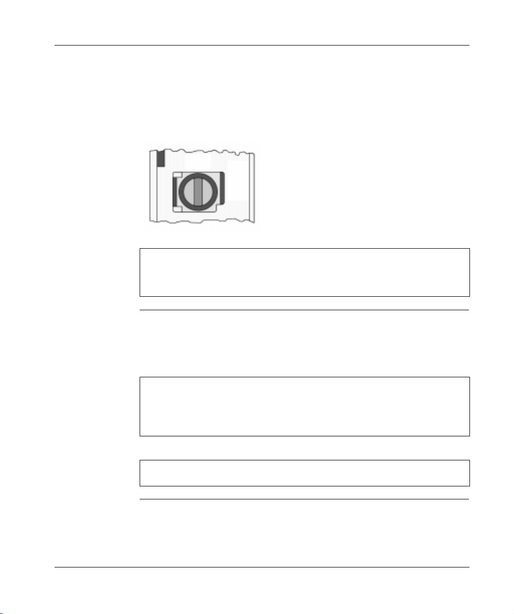
The CHS 110 Hot Standby Module
Topology The following diagram shows the module’s front panel, which consists of:
l
LED Display
l
Function Keyswitch
l
Designation slide switch
l
Update Button
l
Fiber optic cable ports
CHS 110 Front
Panel Controls
The follo wing figure s hows the module’s front panel.
Version Label
Model Number Module
Description Color Code
LED Display
Function Keyswitch
Designation Slide Switch
Update Button
Transmit Cable Connector
Receive Cable Connector
M0035300
Removable Door
18
840 USE 106 00 January 2003
Page 19

Overview of Quantum Hot Standby
140
CHS 110 00
HOT STANDBY
Active
Ready Fault
Run Bal Low
Pwr ok
Modbus Com Err
Modbus! Error A
Com Act Error B
Primary
Mem Prt Standby
LED Display The following illustration shows five status indicators on the face of each CHS 110
module.
The following table shows the five status indicators.
Indicator Color Message
Ready Green If steady, power is being supplied to the module and it has
passed initial internal diagnostic tests. If blinking, module is
trying to recover from an interface error.
Com Act Green If steady, CHS 110 modules are communicating. If blinking, an
error has been detected.
Primary Green Module is Primary controller.
Com Err Red Module is retrying CHS communications or CHS
communications failure has been detected.
Standby Amber If steady, module is Standby controller, and is ready to assume
Primary role if needed. If blinking, program update is in
progress.
Error messages are discussed in detail in
Com Act Error Patterns, p. 209
840 USE 106 00 January 2003 19
.
Page 20
Overview of Quantum Hot Standby
Function
Keyswitch
Designation
Slide Switch and
Update Button
Beneath the LED display on the face of each CHS 110 control panel is a function
keyswitch. It has three positions : Off Line, Xfer (transfer) and Run . You may use this
switch to force transfer of control functions or to copy the full program from the
Primary controller to the Standby.
The following illustration shows a function keyswitch with three positions: Off LIne,
Xfer and Run.
Off
Line
Xfer
Run
Note: For security or convenience, you can disable the function keyswitch with a
software override. Once the keyswitch is disabled, you can set the module to run
or offline mode with software. This can be especially helpful when the module is
not easily accessible.
A slide switch located below and to the right of the keyswitch is used to designate
the controller as A or B. One unit must be designated as A and the other as B.
Use the Standby Update Button to initiate the Primary to Standby prog ram transfer.
You must have the keyswitch in transfer mode.
20
Note: If the controllers are given identical designations, the system refuses to
acknowledge them both. The first unit to power up will be recognized as the
Primary controller. It is designated A or B according to its switch position. The
second unit remains offline and the ComAct indicator flashes, indicating a startup
error.
Note: Once the syst em is running , Primary cont rol may be ex changed betwee n the
units regardless of which is designated as A or B.
840 USE 106 00 January 2003
Page 21

1.2 Operation
Modes of Operation
Overview of Quantum Hot Standby
HSBY Modes of
Operation
Off Line Mode This mode is used to take a controller out of service without stopping it or
Transfer Mode This mode is used to requ est a progra m update of th e Standby cont roller from the
HSBY has three Modes of Operation:
1. Off Line Mode
2. Transfer Mode
3. Run Mode
These modes are described below.
disconnecting power. If you turn the key on the Primary unit to Off Line, control
switches to the Standby. If the Standby controller is taken offline, the Primary
continues to operate without a backup.
Primary controller. For a step-by-step description of the procedure refer to
Replacement, p. 192
The Primary controller is able to update the Standby without any interruption in its
other functions. If the Primary unit is in Run mode and you hold down the update
button on the Standby unit, the Hot Standby modules prepare to copy the full
program of the Primary controller to the Standby unit. The program includes the
configuration table, I/O map, configuration extensions, segment scheduler, user
logic, all .EXE loadables, ASCII messages and the entire state RAM.
To complete the transfer, while continuing to press the update button, turn the key
on the Standby to transfer. The Com Act LED extinguishes. Turn the key to the
mode you want the Standby to assume after the update, Run or Off Line. The
Standby indicator flashes. Release the update button.
.
The Standby indicator continues to flash during the update and while the Standby
unit processes the update. If the unit is set to run mode, the Standby indicator
returns to a steady amber. If the unit is set to offline mode, the Standby indicator
extinguishes. Remove the key.
840 USE 106 00 January 2003 21
Page 22

Overview of Quantum Hot Standby
Note: If you turn the key on the Primary unit to transfer, the Hot Standby system
ignores your action.
Run Mode When the keyswitch is in this position, the controller is active and is either serving
as the Primary controller or is capable of taking over the Primary role, if needed.
The keyswitch on both Hot Standby modules should be in the Run position at all
times. When the Standby con trol ler is in Run mode and the st andby indica tor is on ,
it is actively monitoring the status of the system and is ready to take control if the
Primary unit fails.
22
840 USE 106 00 January 2003
Page 23

Overview of Quantum Hot Standby
1.3 Cabling
Introduction
Purpose This section describes cabling for CHS 110 Hot Standby modules.
What’s in this
Section?
This section contains the following topics:
Topic Page
Fiber Optic Cable 24
The CHS 210 Hot Standby Kit 25
840 USE 106 00 January 2003 23
Page 24

Overview of Quantum Hot Standby
Fiber Optic Cable
Cable
Connections
The CHS 110 Hot Stan dby module s are c onnected by a fiber op tic cable . The cab le
has two identical strands. Each strand transmits a signal in only one direction. For
this reason, each strand must be connected between the upper (transmit) port on
one module and the lower (receive) port on the other.
If the cable is not connected properly, the Hot Standby modules are not able to
communicate and t he Hot Standby syst em does not functi on. The Primary con troller
operates without a backup. The Standby unit remains offline.
A 3 meter fiber op tic c ab le is p r ov ide d in the 140 CHS 210 00 Hot Standby kit. One
strand of that cable is marked wit h the manu facturer’s name. This is the onl y way to
distinguish the two strands.
This illustration shows CHS 110 Hot Standby modules connected by a fiber optic
cable.
Transmit
Receive
Transmit
Receive
24
840 USE 106 00 January 2003
Page 25

Overview of Quantum Hot Standby
The CHS 210 Hot Standby Kit
Contents of Kit Each 140 CHS 210 00 Hot Standby kit contains the following parts. Part numbers
are listed in parentheses.
l
Two CHS 110 Hot Standby modules with four fiber cable clasps (140 CHS 110
00)
l
A 3 meter duplex fiber optic cable (990 XCA 656 09)
l
Two coaxial splitters together with two tap terminators and four self-term inating F
adapters (140 CHS 320 00)
l
A 3 1/2 in. diskette with the CHS loadable (140 SHS 945 00)
l
Quantum Hot Standby Planning and Installation Guide,
840 USE 106 00 Version 2
840 USE 106 00 January 2003 25
Page 26

Overview of Quantum Hot Standby
1.4 984 HSBY and IEC HSBY
Introduction
Purpose This section describes 984 HSBY and IEC HSBY.
What’s in this
Section?
This section contains the following topics:
Topic Page
984 HSBY 27
IEC HSBY 28
26
840 USE 106 00 January 2003
Page 27

Overview of Quantum Hot Standby
984 HSBY
984HSBY In a 984 HSBY system, the user application is written in 984 ladder logic.
HSBY mode can be activated by implementation of a CHS loadable function block
into logic, like the earl ier PLC systems used the "HSBY" l oadable function bloc k. 984
HSBY may also be activated as a configuration extension that allows additional
features to be configured. F or detail s refer to
.
p. 67
Architecture Quantum 984 Hot Standby involves:
l
Concept Version 2.1 or greater, Modso ft Version 2.3 or greater, Proworx Version
1.5 or greater
l
All Quantum Controllers
l
The existing CHS Modules and Execs (CHS 110 00)
Changes to the running application are possible only by download changes to the
Primary controller, whereby the Standby goes offline until it gets updated again by
using the UPDATE push button (refer to
Using a Quantum 984 HSBY System,
Replacement, p. 192
).
System
Compatibility
840 USE 106 00 January 2003 27
Minimum Module Versions to Support 984 HSBY
Module Version PV / SV
140 CPU x13 0x 2.1 All
140 CPU 424 02 2.1 All
140 CPU x34 1x All All
140 CRP 93x 00 2.1 All
140 NOM 2xx 00 2.1 All
Page 28

Overview of Quantum Hot Standby
IEC HSBY
IEC HSBY
Architecture
IEC Hot Standby means: Pro gram m ing an application with the c ho ice of 5 different
IEC compliant languages; FBD, LD, SFC, IL and ST.
1. The IEC HSBY system uses the same hardware architectures as 984 HSBY
system for its basic operations. For example, state RAM data transfer and
switchover contro l are the same, b ut there are some differe nces compa red to the
984 HSBY system.
2. PLC firmware upgrade is allowed without shutting down the system with Concept
2.5 or higher. Earlier versions of Concept require shutting down the sys tem to
upgrade PLC firmware.
3. RIO is serviced differently.
4. With Concept 2.5 or higher, it is now possible to download the same appli ca tio n
to Primary and to the Standby controller. The result is that the Hot Standby
system will be fully setup (equalized) with identical applications in both
controllers. Earlier versions of Concept require you to use the UPDATE bush
button (refer to
Using a Quantum IEC Hot Standby Sys tem , p. 109
) on the CHS
module in the Standby rack to equalize both controllers. Therefore, the same
application including the configuration will be running in both controllers.
5. There’s no CHS function block used in IEC.
28
840 USE 106 00 January 2003
Page 29

Overview of Quantum Hot Standby
Architecture As shown below, Quantum IEC Hot Standby involves:
l
Concept Version 2.1 or greater
l
Two High End Quantum Controllers (CPU 434 12 or CPU 534 14)
l
The existing CHS Modules and Execs (CHS 110 00). The existing RIO Heads
with version 2.0 Execs or greater (CRP 93x).
l
All five IEC 1131 languages can be used, however 984 Ladder Logic cannot be
used.
The follow ing diagram shows the Quantum IEC Hot Standby Architect ure
Quantum IEC Hot Standby Architecture
&RQFHSW9RUKLJKHU
1R/DGGHU/RJLF
4XDQWXP&RQWUROOHUV
&38
&38
([LVWLQJ&+6PRGXOH
KDUGZDUHDQG([HFV
([LVWLQJ5HPRWH,2
PRGXOHVDQG([HFV
&(PDUNHG9HUVLRQ
RUJUHDWHU
PRIMARY SECONDARY
FIBER OPTIC CHS LINK
REMOTE I/O
0RGEXV3OXV
With Concept 2.1/2.2 , changes to the running application are possible only by
download changes to the Primary controller, whereby the Standby controller goes
offline until it gets updated again by using the UPDATE push button (refer to
Updating PLC System Executives in an IEC HSBY System, p. 200
). Concept 2.5
supports the Logic Mismatch option on the Hot Standby Configuration Extension
which allows the Standby controller to remain online with a different program than
the Primary controller.
Note: Unlike Concept 2.1, with Concept 2.2/2.5 it is possible to make changes to
the IEC logic offline and downlo ad them as online changes later. I t is not necessary
to be connected to the controller at the time of editing the IEC logic.
840 USE 106 00 January 2003 29
Page 30

Overview of Quantum Hot Standby
Application size For basic mechanisms (data and program transfer), the IEC HSBY and the 984
HSBY system operate in the same manner. The data transfer during normal
operation, accomp lished by copyi ng the state RAM from the Primary to the Standby,
causes differences in te rms of application si ze. In IEC HSBY, a part of the state RAM
is used to transport the IEC application data from the Primary to the Standby.
Therefore the size of IEC appli catio n data c annot ex ceed the con figured size o f the
state RAM itself. The absolute maximum for IEC application data is 128K (64K
words of state RAM). For the size of an IEC application’s executable code there is
also a limit of 568K under Concept 2.1/2.2. The IEC application’s executable code
limit was increased to 1 Megabyte for Concept 2.5.
Quantum IEC Hot
Standby
Overview
l
IEC Language programs only, no 984 Ladder Logic permitted
l
To bring a Standby on-li ne
l
Primary and Standby controller executives must be equal.
l
Primary and Standby IEC Projects must have the same name and the
applications must be equal.
l
On-line changes to the Primary are permitted
l
With Concept 2.1/2.2, the Standby controller is taken off-line as soon as the
first Primary on-line change is made. The Primary program must be
transferred to the Standby before it can be brought back on-line.
l
Concept 2.5 supports Logic Mismatch in the Hot Standby configuration
extension. This option allows the Standby controller to remain online with a
different program than the primary controller.
l
Primary controller on-line changes may include
l
Addition of sections
l
Addition of DFBs allows pre-qualification of user changes in an office
environment
l
Logic Mismatch
l
With Concept 2.1/2.2, it is not possible to load a new version of the application
on Standby, bring it on-line, and transfer control to make it the new Primary.
l
Under Concept 2.5, with Logic Mismatch enabled, a new version of the
application can be downloaded to the Standby controller and brought online.
Control can then be transferred to the Standby controller to make it the new
Primary controller.
l
To upgrade the controller Execs
l
With Concept 2.1/2.2, the process must be stopped. Then Primary and
Standby controllers must be stopped and downloaded individually.
l
Under Concept 2.5, the controller executives can be upgraded while the
process continues to run.
30
840 USE 106 00 January 2003
Page 31

Theory of 984 Ladder Logic HSBY
Operation
At a Glance
Purpose This chapter covers the 984 Hot Standby and its theory of operation.
2
What’s in this
Chapter?
This chapter contains the following topics:
Topic Page
How a 984 HSBY System Works 32
System Scan Time 33
The State RAM Transfer and Scan Time 36
Default Transfer Area 38
Customizing Options 40
Custom Scans 41
840 USE 106 00 January 2003 31
Page 32

Theory of 984 HSBY Operation
How a 984 HSBY System Works
984 Theory Both the Primary and the Standby backplanes contain a CHS 110 Hot Standby
module. The modules moni tor their own controll er CPU and communica te with each
other via fiber link. The Primary contro ller keeps th e Standby info rmed of the current
state of the application by transferring state RAM values to the Standby controller
during every logic scan. RIO head communications are also verified.
Stages of State
RAM Transfer
State RAM
Transfer
A Hot Standby system transfers state RAM data from the Primary to the Standby
controller while the Primary co ntrolle r scans and so lves the ladder log ic appli catio n
program. There are three steps in this transfer process:
1 Primary controller-to-Primary CHS 110 state RAM transfer.
2 Primary CHS 110-to-Standby CHS 110 state RAM transfer.
3 Standby CHS 110-to-Standby controller state RAM transfer.
The Primary CHS 110 Hot Standby module initiates the state RAM transfer
operation. The module requests specified state RAM information from the Primary
controller.
At the beginning of ea ch scan, the Primary controller transfer s the current state RAM
data to the CHS 110 Hot Standby module.
As soon as the transfer (controller-to-CHS 110) finishes, the Primary controller
resumes scanning user logic and servicing I/O. The state RAM data is
simultaneously tra ns ferre d from the Prim ary C HS 11 0 mo dul e to th e Standby CHS
110 module over the fiber optic link at a rate of 10 megabaud. In turn, the Standby
CHS 110 module transfers the state RAM data to the Standby controller.
Note: Schneider Elect ric defi ne s Sta te RAM as RA M m em ory that is used to hold
register and discrete inputs and outputs and internal data storage. State RAM is
allocated to the four different reference types: 0xxxx, 1xxxx, 3xxxx, and 4xxxx.
32
840 USE 106 00 January 2003
Page 33

System Scan Time
Theory of 984 HSBY Operation
Effect on System
Scan Time
Primary Rack
PLC
Transfer (over the Q uantum Backplane)
CHS 110
Standby Rack
CHS 110
PLC
When the ladder logic program being executed by the primary controller is longer
than the CHS 110-to-CHS 110 transfe r, the transfer does not incre ase total sy stem
scan time. However, if the ladder logic program is relatively short, the scan finishes
before the CHS 110-t o-CH S 1 10 data transfer and the d ata tra ns fer inc rea ses total
system scan time.
The following timing diagram shows how the transfer takes place.
1 Scan
Solve All Segments
PLC-to-CHS 110 State RAM
CHS 110-to-CHS 110 State RAM
Transfer (Over Fiber O ptic HSBY Link)
CHS 110-to-PLC State RAM Transfer
Solve Segment 1 Solve Segment 1
1 Scan
The effect on system sc an time of any Hot Standby s ys tem dep en ds v ery mu ch on
how much state RAM is going to be transferred from Primary to Standby. A Hot
Standby system always has a higher scan time than a comparable standalone
system because of the required PLC to CHS data transfer time.
Since the data transfer depends on the PLC type in the system, the following
provides information that allows you to forecast a Hot Standby system‘s scan time:
l
Calculation of ov era ll scan time for a n orm al Hot Standby baseline co nfi gura tion
containing minimum logic as a reference
l
Calculation of a PLC specific constant that expresses the increase of overall scan
time related to an increase of state RAM memory to be transferred
840 USE 106 00 January 2003 33
Page 34

Theory of 984 HSBY Operation
The normal Hot Standby configuration contains:
l
In the local rack: power supply (CPS), PLC (CPU), RIO Head (CRP 93x), Hot
Standby module (CHS)
l
In one remote IO drop equipped with 8 I/O modules, power supply (CPS) and
remote adapter (CRA)
l
Only the logic for the scan time evaluation
PLC Scan Times The scan time increase with different PLCs, after adding HSBY, is outlined in the
Scan Time Increase tabl e belo w .
CPU - HSBY Baseline
Configuration
CPU x13 0x0x: 1536, 1x: 512, 3x:
3000, 4x: 1872
CPU 424 020x: 1536, 1x: 512, 3x:
1212, 4x: 1872
CPU 434 12 / CPU 534 140x:
1536, 1x: 512, 3x: 512, 4x: 1872
Scantime Increase
because of HSBY
~ 25 ms 984 Ladder Logic only
~ 40 ms 984 Ladder Logic only
~ 40 ms 984 Ladder Logic only
Languages Supported
PLC to CHS Data
Transfer Rate
The investigation of the PLC specific data transfer rate in a Hot Standby system
leads to th e following results.
CPU x13 0x 1.6 ms / byte
CPU 424 02 2.0 ms / byte
CPU 434 12 /
CPU 534 14
1.9 ms / byte
State RAM The following table lists the nu mb er of b yt es required for reference st orag e in state
RAM.
Coil (0x) 3 bit
Discrete (1x) 3 bit
Input Register (3x) 2 bytes
Holding Register (4x) 2 bytes plus 2 bit
Based on the data shown in the tables above you ma y forecast the ove rall scan time
of a Hot Standby system once you know how much state RAM is going to be
transferred and the tim e re qui red for a particular logic ap pli cat io n to be ex ec ute d i n
a standalone system.
34
840 USE 106 00 January 2003
Page 35

Theory of 984 HSBY Operation
Example This example shows th e effect of a co nfiguratio n change fro m baselin e as show n in
the Scan Time Increase Table in
PLC Scan Times, p. 34
.
A particular HSBY applic ation ha s a standa lone scan time o f 36 ms i n a PLC o f type
CPU 424 02. The state RAM to be transferred consists of 3000 coils (0x), 2500
discrete inputs (1x), 2500 input registers (3x) and 8000 holding registers (4x).
The state RAM difference to the reference configuration is shown in the Effects of
a Configuration Change from Baseline table below:
0x3000 - 1563 =
1464
1x2500 - 512 =
1988
3x2500 - 1212 =
1288
4x8000 - 1872 =
6128
Total: 17659 bytes = scan time offset = 17659 * 1.6ms ~ 28ms
1464*3/8 =549 Bytes
1988*3/8 = 746 Bytes
1288*2 = 2576 Bytes
6128*2 + (6128*2/8) = 13788 Bytes
This application therefore would have an overall scan time in Hot Standby:
40 ms (reference with CPU 424 02 0x) added by HSBY
+ 36 ms (standalone scan time)
+ 28 ms (offset through configuration increase)
=104 ms
Note: No matter how long your transfer takes, it does not cause a watchdog
timeout.
840 USE 106 00 January 2003 35
Page 36

Theory of 984 HSBY Operation
The State RAM Transfer and Scan Time
Reduce Scan
Time
This section describes manipulating the state RAM transfer to reduce scan time
Note: The state RAM transfer area contains all the state RAM values that are
passed between th e Primary a nd Standby controllers. The size of the transfer area
may be as large as the total size of your controller’s state RAM or a portion
containing critical I/O reference data types.
As the simplified block diagram below shows, all 0x references in the state RAM
transfer area are transferred first, then all 1x references, followed by all the 3x
references, and finally all the 4x references:
Total number of discrete
outputs transferred
0nnnnn
Total number of discrete
inputs transferred
1nnnnn
Total number of register
inputs transferred
Where nnnnn is a
multiple of 16
36
3nnnnn
Total number of register
outputs transferred
4nnnnn
840 USE 106 00 January 2003
Page 37

Theory of 984 HSBY Operation
1. Reduce the reference configuration to minimum requirements (0x, 1x, 3x, 4x).
Minimizing the state RAM area is one way to reduce scan time.
2. Another way is to define regis ters in a non-trans fer area, an area contained withi n
the state RAM transfer area but ignored d uring the actual state RAM transfer.
3. Use the HSBY configuration extension to define transfer amounts.
Note: If you are customizing the size of your state RAM transfer area, you must
specify the number of each reference data type (0x, 1x, 3x, and 4x) as either 0 or
a multiple of 16. In the case of the 4x registers, there must always be at least 16
registers allotted.
840 USE 106 00 January 2003 37
Page 38

Theory of 984 HSBY Operation
Default Transfer Area
Automatic
Transfer
By default, the Hot Standby system automatically transfers the following from the
Primary to the Standby controller on every scan:
l
The first 8192 points of 0x output reference data
l
The first 8192 points of 1x input reference data
l
A total of 10K registers, of which 1K is allotted for 3x registers and 9K is allotted
for 4x registers.
In any case, the number of 4x registers transferred is a multiple of 16 unless all 4x
registers have been included. The number of 4x registers may slightly exceed the
allotment in order to r each the next highest multiple of 16.
Any state RAM values above the limits shown in the following diagram are not
included in the state RAM transfer area and therefore are not shared with the
Standby controller. The state RAM values in the range above these limits must not
contain the command register or control critical I/O.
38
840 USE 106 00 January 2003
Page 39

Theory of 984 HSBY Operation
The diagram below shows examples of the data transfer area for different
configurations of 3x and 4x regist ers .
Example 1
If you have 3200 3x and 9600 4x registers, then the
full allotment of 1000 3x registers will be transferred.
The acutual number of 4x registers transferred will be
9008; that is, the full allotment of 9000 registers plus
8 more to reach the next highest multiple of 16.
Transfer Area
Example 2
If you have 3200 3x and 7000 4x registers, then all
the 4x registers will be transferred. The full allotment
of 1000 3x registers will be transferred, plus an
additional 2000 3x registers to bring the total number
of registers transferred to 10,000. So a total of 3000
3x registers will be transferred.
Example 3
If you have 700 3x and 9600 4x registers, then all the
3x registers will be transferred. The full allotment of
9000 4x registers will be transferred, plus an
additional 300 registers to bring the total to 10,000,
plus an additional 12 registers to reach the next
highest multiple of 16. In all, 9312 4x registers will be
transferred.
840 USE 106 00 January 2003 39
Page 40

Theory of 984 HSBY Operation
Customizing Options
Custom State
RAM Transfer
Area
If you want to set up a custom state RAM transfer area, you can control your
transferred amounts u sing a Hot Standby c onfiguration exte nsion (refer to
Guidelines for IEC Hot Standby , p.147
). The configuration extensio n provides three
Additional
alternatives to the default transfer area:
l
You can define the number of 0x, 1x, 3x, and 4x reference data types that you
want transferred in each scan.
l
You can define a certain amount of reference data types to be transferred on
each scan with additional data to be transferred in groups over multiple scans,
beginning with 0x registers and proceeding in turn with 1x, 3x, and 4x registers.
l
You can transfer all the configured reference data types in your system’s state
RAM on every scan.
These options allow you to design a transfer area that is as small as 16 4x output
registers or large enough to enc ompass all of your controll ers’ state RAM (10K, 32K,
or 64K, depending on the type of Quantum controllers you are using in your Hot
Standby system).
The reference data of each type (0x, 1x, 3x, and 4x) is placed in the state RAM
transfer area, starting at the lowest reference number (000001 for coils, 100001 for
discrete inputs, 300001 for register inputs, and 400001 for register outputs). It is
accumulated conti guously up to the amo unt of each data ty pe you specify . The total
number of each refe rence t ype in the st ate RAM transfe r are a mus t be a multip le of
16.
For example, if you indicate that the number of coils in the transfer area is 96, coils
000001... 000096 are tra nsferred from the Primary to th e Standby co ntroller. Any 0 x
references beyond 000096 used in state RAM are not transferred.
40
The additional stat e R AM dat a to be sent over multiple sc ans c an a ls o be of any or
all of the four reference data types, and must also be specified in multiples of 16.
The additional referen ce data region for eac h data type starts a t the lowest availa ble
reference number. For example, if 2048 coils are transferred on every scan
(000001... 002048), an d you schedule 1024 ad ditional coils for tra nsfer over multiple
scans, references 002049... 003072 are used for the additional transfer data.
The additional transfer is hand led by specifyin g the number of scans over wh ich you
want to send the additional data. For example, if you specify two scans in which to
transfer coils 002049... 003072, then coils 002049... 002560 are sent with coils
000001... 002048 on o ne scan and coil s 002561.. . 003072 are tran sferred with coi ls
000001... 002048 on the next scan.
840 USE 106 00 January 2003
Page 41

Custom Scans
Theory of 984 HSBY Operation
Setting up
Custom Scans
The following block diagram shows how the state RAM transfer area might be set
up using multiple scans to transfer all the data.
Total number of discrete
outputs transferred
0nnnnn
Total number of discrete
inputs transferred
1nnnnn
Total number of register
inputs transferred
3nnnnn
Total number of register
outputs transferred
Critical outputs transferred on
every scan
Additional outputs transferred
in chunks on multiple scans
Critical inputs transferred on
every scan
Additional inputs transferred
in chunks on multiple scans
Critical inputs transferred on
every scan
Additional inputs transferred
in chunks on multiple scans
Critical outputs transferred on
every scan
Additional outputs transferred
4nnnnn
840 USE 106 00 January 2003 41
in chunks on multiple scans
Page 42

Theory of 984 HSBY Operation
42
840 USE 106 00 January 2003
Page 43

Theory of IEC HSBY Operation
3
At a Glance
Purpose This chapter presents the Theory of Operation for the IEC Hot Standby system.
What’s in this
Chapter?
This chapter contains the following topics:
Topic Page
IEC Hot Standby Definitions 44
How an IEC HSBY System Works 46
System Scan Time 47
State Ram Transfer and Scan Time 51
Layout of completely transferred state RAM in an IEC Hot Standby system 53
840 USE 106 00 January 2003 43
Page 44

Theory of IEC HSBY Operation
IEC Hot Standby Definitions
Definitions The following are IEC Hot Standby definitions.
Exec: Quantum controller operating system with integrated IEC language support
(IEC runtime system)
Program Data: A continuous memory block containing all program variables,
including:
l
Non-located IEC variables and constants declared in variable editor
l
Links in FBD and LD sections
l
Stack (loop) variables in IL and ST
l
SFC states
l
Literals
l
Pointer lists
l
Internal states of EFBs
DFB Instance Data: Multiple memory blocks containing:
l
Internal data of each DFB instance
l
Process diagnostics buffer
l
Mirror buffer: 1 Byte per configu red 0x/1x ref erence (only Conc ept 2.1 an d older)
l
Used references list: 1 Bit per configured 0x/1x reference
44
IEC Heap: One continuous memory block containing:
l
Program data
l
DFB instance data
Maximum IEC Heap Size: 128 KByte together with state RAM. If 10K Words (20
KByte) of state RAM are used already for I/O references the max. IEC heap size
would be 128 KByte – 20 KByte = 108 KByte
Currently used IEC Heap Size: DFB instance data plus (configured) program data
area size
State Table: Also called state RAM, controller refere nces for both real world I/O and
internal referenced (located) variables
Project: Concept prog ram fi le containing control le r co nfi gura t io n a nd IEC l ang uag e
control code
Application: Downloaded IEC language control code and data
840 USE 106 00 January 2003
Page 45

Theory of IEC HSBY Operation
IEC Heap The m ost importan t new t erms to und erstand i n IEC Hot Standby are the IEC Heap,
the Currently used IEC Heap Size and the Maximum IEC Heap Size.
Program Data
Area
The program data area has a default size of 16 KByte whenever a new Concept
project is created. Its size may be adjusted to the amount of memory that’s really
needed for a particul ar application. This can be do ne in the Memory Statistics Dia log
while Concept is not connected to the PLC. This dialog can be activated through
Online --> Memory Statistics.
Configure size of p rogra m dat a area at the Memo ry Stat ist ics dial og in of fline mod e.
Note: Ch anging the c onfigured size of the program data area results in a complete
download of the application, no download changes are possible.
The maximum size of the IEC heap is the maximum amount of memory available for
data in any particula r IEC application. What this means in terms of IEC H SBY is
shown in the diagram in
All State RAM transferred, p. 52
.
840 USE 106 00 January 2003 45
Page 46

Theory of IEC HSBY Operation
How an IEC HSBY System Works
IEC Theory Both the Primary and the Standby backplanes contain a CHS 110 Hot Standby
module. The modules moni tor their own controll er CPU and communica te with each
other via fiber link. The Primary contro ller keeps th e Standby info rmed of the current
state of the application by transferring state RAM values to the Standby controller
during every logic scan. RIO head communications are also verified.
State RAM
Transfer
State RAM
Defined
State RAM
Transfer Initiated
A Hot Standby system transfers state RAM data from the Primary to the Standby
controller while the Primary controller scans and solves the IEC logic application
program. There are three steps in the transfer process:
Stage Description
1 Primary controller-to-Primary CHS 110 state RAM transfer.
2 Primary CHS 110-to-Standby CHS 110 state RAM transfer.
3 Standby CHS 110-to-Standby controller state RAM transfer.
Note: Schneider El ect ric defi ne s Sta te R AM as RAM m em ory that is use d to hol d
register and discrete inputs and outputs and internal data storage. State RAM is
allocated to the four different reference types: 0xxxx, 1xxxx, 3xxxx, and 4xxxx.
The state RAM transfer operation is initiated by the Primary CHS 110 Hot Standby
module. The module requests specified state RAM information from the Primary
controller.
At the beginning of ea ch scan, the Primary controller transfer s the current state RAM
data to the CHS 110 Hot Standby module.
As soon as the controller-to-CHS 110 transfer finishes, the Primary controller
resumes scanning user logic and servicing I/O. The state RAM data is
simultaneously tra ns ferre d from the Prim ary C HS 11 0 mo dul e to th e Standby CHS
110 module over the fiber optic link at a rate of 10 megabaud. In turn, the Standby
CHS 110 module transfers the state RAM data to the Standby controller.
46
840 USE 106 00 January 2003
Page 47

System Scan Time
Theory of IEC HSBY Operation
Effect on System
Scan Time
The effect on system scan time of any Hot Standby system depends on how much
state RAM is going t o be transferred from Prim ary to Standby. A Hot Sta ndby system
always has a higher scan time than a comparable standalone system.
The following has be en done to provide i nformation th at allows y ou to forecas t a Hot
Standby system’s scan time:
l
Calculation of ov era ll scan time for a n orm al Hot Standby baseline co nfi gura tion
containing minimum logic as a reference
l
Calculation of a PLC specific constant that expresses the increase of overall scan
time related to an increase of memory to be transferred
The normal Hot Standby configuration state RAM contains:
l
In the local rack: power supply (CPS), PLC (CPU), RIO Head (CRP 93x), Hot
Standby module (CHS)
l
In one remote IO drop equipped with 8 I/O modules, power supply (CPS) and
remote adapter (CRA)
l
Only the logic for the scan time evaluation
840 USE 106 00 January 2003 47
Page 48

Theory of IEC HSBY Operation
Transfer diagram The following shows a transfer diagram:
Primary Rack
1 Scan
CPU
State RAM & IEC
Heap download
128K
bytes
CHS
Standby Rack
CHS
Diag Diag DiagCommComm
CPU
Comm DiagIEC Logic Solve Comm DiagIEC Logic Solve IEC Logic Solve Diag
State RAM & IEC
Heap download (Over the
Fiber Optic HSBY link)
128K
bytes
1 Scan
128K
bytes
128K
bytes
State RAM & IEC
Heap download
128K
bytes
128K
bytes
Note: The size of 128K bytes state RAM memory in the timing diagram being
transferred with each scan is not a fixe d valu e. It ex press es the maximu m am ount
of data handled by the CHS module during a data transfer. This is a hardware
limitation. Therefore , the maximum State RAM li mit ati on fo r the IEC user is 128 K
bytes. Unlike a 984 HSBY system, the Stand by cont roll er doesn’t solve any logic.
With the new exec s delivered with Concept 2.5, the Standby Controller solv es logic
in Section 1.
48
840 USE 106 00 January 2003
Page 49

Theory of IEC HSBY Operation
Overall PLC Scan
Time
PLC to CHS Data
Transfer Rate
The overall scan time for the IEC HSBY supporting PLC type is outlined in the IEC
Scan Time Increase Table below.
IEC Scan Time Increase
CPU - HSBY Baseline Configuration Scantime Increase because of HSBY
CPU 434 12 / CPU 534 14
0x: 1536, 1x: 512, 3x: 512, 4x: 1872
IEC-HSBY registers (3x): 700
~ 40 ms
Calculating the PLC specific d ata transfe r rate in a Hot Standb y syste m leads to the
following result.
CPU 434 12 / 534 14 1.9 ms / byte
State RAM The following table lists the number of bytes required for reference storage
Coil (0x) 3 bits
Discrete (1x) 3 bits
Input Register (3x) 2 bytes
Holding Register (4x) 2 bytes plus 2 bits
IEC HSBY Register (3x) 2 bytes
840 USE 106 00 January 2003 49
Page 50

Theory of IEC HSBY Operation
Example This example shows the eff ect of a c onfiguratio n change fro m baselin e as shown in
the IEC Scan Time Increase Table (See
Overall PLC Scan Time, p. 49
).
A particular applicati on h as a sta nda lo ne s ca n tim e of 25 ms in a PLC of type CPU
434 12. The state RAM to be transferred consists of 200 coils (0x), 300 discrete
inputs (1x), 150 input re gisters (3x), 400 ho lding registers (4x) and 14000 IEC HSBY
registers (3x).
The state RA M difference to the ref erence configuration is:
Effects of a Configuration Change from Baseline
0x
200 - 1536 = - 1336 -1336*3/8 = - 501 Bytes
1x
300 - 512 = - 212 - 213*3/8 = - 80 Bytes
3x
150 - 512 = - 362 - 362*2 = - 724 Bytes
4x
400 - 1872 = - 1472 -1472*2 + ( - 1472*2/8)| = - 3312 Bytes
IEC Hot Standby regs 14000(3x) = 14000*2 = 28000 bytes Total = 28000 - 501 - 80 - 724
- 3312 = 23383 bytes Scan time offset = 23383*1.9ms ~ 44ms
This application therefore would have an overall scan time in Hot Standby:
40 ms (reference with CPU 434 12/ 534 14)
+ 25 ms (logic solve)
+ 44 ms (offset through memory increase)
= 109 ms
50
840 USE 106 00 January 2003
Page 51

State Ram Transfer and Scan Time
Theory of IEC HSBY Operation
Reduce Scan
Time
The state RAM transfer area contains all the state RAM values that are passed
between the Primary and Standby controllers. The size of the transfer area is as
large as the total size of your controller’s state RAM.
As the simplified block diagram below shows, all 0x references in the state RAM
transfer area are transferred first, then all 1x references, followed by all the 3x
references, and finally all the 4x references.
In the Quantum HSBY system, IEC HSBY does not allow customizing the transfer
area. This means the whole state RAM is transferred in IEC HSBY, except for the
nontransfer area, an area contained within the transfer area but ignored during the
actual state RAM transfer. Placing registers in the nontransfer area is one way to
reduce scan time because the Primary controller to CHS transfer time is shorter.
With Concept 2.5, a new function called Section Transfer Control has been added
which can be used to reduce scan time. See
Section Transfer Control, p. 135
for
further information on this feature.
Note: No matter how long your transfer takes, it does not cause a watchdog
timeout.
840 USE 106 00 January 2003 51
Page 52

Theory of IEC HSBY Operation
All State RAM
transferred
The following diagram shows the state RAM transfer area.
Total number of discrete
outputs transferred
0nnnnn
Total number of discrete
inputs transferred
1nnnnn
Total number of register
inputs transferred
3nnnnn
Total number of register
outputs transferred
4nnnnn
Where nnnnn is a
multiple of 16
Note: No 3x registers
configured for IEC HSBY
52
840 USE 106 00 January 2003
Page 53

Theory of IEC HSBY Operation
Layout of completely transferred state RAM in an IEC Hot Standby system
Layout of
transferred RAM
State RAM
(Compl. xferred)
Total 0x
Total 1xTotal 3x
The diagram below illustrates that a significant piece of the controller’s state RAM is
taken as a transfer buffer for co pying the IE C he ap from t he Primary t o the Standby
controller. The transfer header is located at the very top of the transfer buffer. The
transfer header contains information about the Primary’s exec version, time
synchronization information and the IEC application’s version. This information
allows the Standby control ler, once it rec eived the trans fer buffer, to decide whether
to remain online or go offline. When online, the Standby controller copies the
Primary’s IEC heap out of the transfer buffer into its internal memory, which ensures
the Standby’s IEC data consistency.
Header
(Exec Vers.,
Timing Info, ..,)
Program Data
Used
Prog. Data
Configured
Program Data
Unused
Safety Buffer
for Future
changes/additions
DFB Instance
Data
No. 3x regs
Configured
for IEC HSBY
Transfer Buffer for IEC Heap
Total 4x
840 USE 106 00 January 2003 53
Space as big as IEC heap
Free Memory
for addtl DFB
Instance Data
Page 54

Theory of IEC HSBY Operation
54
840 USE 106 00 January 2003
Page 55

Planning a Quantum Hot Standby
System
At a Glance
Purpose This chapter describes how to plan a Quantum Hot Standby System.
4
What’s in this
Chapter?
This chapter contains the following topics:
Topic Page
Guidelines for Planning a Hot Standby System 56
Electrical Safety Precautions 57
Remote I/O Cable Topologies 58
A Single Cable Configuration 59
A Dual Cable Configuration 60
840 USE 106 00 January 2003 55
Page 56

Planning a Quantum Hot Standby System
Guidelines for Planning a Hot Standby System
Primary and
Standby
Controllers
Both the primary and the standby contr oller in your Hot Standby system must be
ready to perform as a stand-alone controller in the event that its counterpart fails.
Therefore, you should ins tall them with equal ca re, according to Modi con’s standard
planning and installation guidelines. Refer to the
Hardware Reference Guide,
Planning and Installation Guide,
840 USE 100 00, and the
890 USE 101 00, for details.
Quantum Automation Series
Remote I/O Cable System
Design your system for safety first, then for economy. Be sure that you understand
all the cautions a nd warni ngs in this manua l befo re you begin to ins tall y our sy stem.
For the Hot Standby system to function, your component modules must meet the
version requirements in
Overview of Quantum Hot Standby, p. 13
.
You must use identical modules in the primary and standby racks. If you have
different models or diffe rent ver sions of the sam e mode l or diff erent fl ash ex ecutive
software, the Hot Standby system will not function properly.
Note: The order of the modules in the backplanes must be the same.
While the controllers and RIO heads must be Quantum models, the remote drops
may use Quantum, 800 serie s, 500 series or 200 serie s I/O with correspondi ng drop
processors.
Positioning The CHS 110 Hot Standby modules are connected by fiber optic cable. A 3 meter
cable is supplied w ith the ki t. However, th e primary an d standby b ackplanes may be
placed as much as 1 km apart. If you will be placing the modules more th an 3 m
apart, use 62.5/125 micro meter cable with ST-styl e connectors. Ref er to
Cable Guide, p.213
for details.
Fiber Optic
56
If you intend to place the units more than 3 meters apart, you must consider the
effect on the RIO network and any Modbus Plus network.
The controllers are linked to the RIO network by coaxial cable. The longer the
distance between the controllers, the higher the grade of trunk cable required to
maintain signal integrity. Refer to Chapter 3 of the
Planning and Installati on Guide
, 890 USE 101 00, for details regarding cable grades,
Remote I/O Cable System
distances and signal integrity. If no coaxial cable will be sufficient to maintain signal
integrity throughout the RIO network , fiber optic repeat ers may be used to boos t the
signal. Refer to t he
100 00,
for details on extending a Modbus Plus network.
Modbus Plus Network Pla nning and Installat ion Guide,
840 USE 106 00 January 2003
890 USE
Page 57

Electrical Safety Precautions
Safety
Precautions
WARNING
To protect yourself and others against electric shock, obey your
national electrical code and all applicable local codes and laws.
When you plan the installation of the electrical cabinets which enclose
the system’s elect ronic components, be sure each cabinet is con nected
separately to earth ground and that each backplane is connected to
solid ground within its cabinet.
Failure to follow this precaution can result in death, serious inju ry,
or equipment damage.
Planning a Quantum Hot Standby System
840 USE 106 00 January 2003 57
Page 58

Planning a Quantum Hot Standby System
Remote I/O Cable Topologies
Cable
Connections
In each configuration:
l
The cables connecting the RIO head processors to the RIO network must be
fitted with self-terminating F adapters.
l
An MA-0186-100 coaxial splitter must be installed between the RIO head
processors and the RIO network.
l
The remote drops must be connecte d to the trunk ca ble via an M A-0185-100 tap
and a 97-5750-000 (RG-6) drop cable.
l
The last tap on a trunk cable must be terminated with a 52-0422-000 trunk
terminator. Remote drops must not be connected directly to the trunk cable.
Refer to the
Remote I/O Cable System Planning and Installation Guide,
890 USE 1001 00, for details.
Note: If you a re using a HSBY for data log ging, the RIO heads must be c onfigured
and connected with coaxi al ca ble .
l
If you are using 984, you must configure 2 or more segments.
l
If you are using IEC, you must configure 2 or more RIO drops.
Note: For ill ustrations of both single c able and dou ble cable c onfigurati ons, please
A Single Cable Configuration, p. 59
see
and
A Dual Cable Configuration, p. 60
.
58
840 USE 106 00 January 2003
Page 59

A Single Cable Configuration
Planning a Quantum Hot Standby System
Diagram of a
Single Cable
Configuration
The following diagram shows a single cable configuration for the Quantum Hot
Standby system.
Primary PLC
Self-terminating
F adapter**
#52-0411-000
RIO Drop #2
Drop Cable*
(RG-6) #97-5750-000
RIO Drop #4
Coaxial Cable
Trunk
Tap #MA-0185-100
Fiber Optic Cable
Splitter
#MA-0186-100
Trunk Cable
(RG-11) #97-5951-000
Tap #MA-0185-100
Drop Cable*
(RG-6) #97-5750-000
Standby PLC
Self-terminating
F adapter**
#52-0411-000
RIO Drop #3
Last RIO Drop
Tap #MA-0185-100
Drop Cable*
(RG-6) #97-5750-000
Trunk Terminator
#52-0422-000
*Premade RG-6 Drop Cable
50’ (14m) AS-MBII-003
140’ (43m) AS-MBII-004
840 USE 106 00 January 2003 59
Tap #MA-0185-100
Drop Cable*
(RG-6) #97-5750-000
**140 CHS 320 00 kit includes:
2 Splitters
4 F Adapters
2 Terminators
See CHS 210 Hot Standby Kit for entire
HSBY kit contents (140 CHS 210 00).
Page 60

Planning a Quantum Hot Standby System
S
C
A Dual Cable Configuration
Diagram of a
Dual Cable
Configuration
The follo wing diagram shows a dual cable configuration for the Quantum Hot
Standby system.
Primary PLC
Self-terminating
F Adapters**
#52-0411-000
RIO Drop #2
RIO Drop #4
Coaxial Cable
Coaxial Cable Splitter #MA-0186-100
Splitter
#MA-0186-100
Drop Cable*
(RG-6) #97-5750-000
Trunk
Line
A
Tap
Fiber Optic Cable
(Trunk Cable (RG-11) #97-5951-000)
Trunk
Line
B
Tap
#MA-0185-100
Drop Cable*
(RG-6) #97-5750-000
tandby PL
Self-terminating
F Adapters**
#52-0411-000
RIO Drop #3
60
Drop Cable*
(RG-6) #97-5750-000
Trunk Terminator
#52-0422-000
Trunk Terminator
*Premade RG-6 Drop Cable
50’ (14m) AS-MBII-003
140’ (43m) AS-MBII-004
Last RIO Drop
Tap
#MA-0185-000
Drop Cable*
(RG-6) #97-5750-000
**140 CHS 320 00 kit includes:
2 Splitters
4 F Adapters
2 Terminators
See CHS 210 Hot Standby Kit for entire
HSBY kit contents (140 CHS 210 00).
840 USE 106 00 January 2003
Page 61

Installation
5
How to Install a Hot Standby System
Procedure This section discusses the procedure for installing a new Hot Standby system. For
more detailed instructions, refer to the
Reference Guide
Installation Guide
, 840 USE 100 00 or the
, 890 USE 101 00.
Quantum Automation Series Hardware
Remote I/O Cable System Planning and
Installing a Hot
Standby System
l
Install the power supplies, controllers, RIO head processors, hot standby
modules and any option modules in the primary and standby backplanes. Be
sure:
l
The modules meet the version requirements listed in
Standby, p. 13
l
The modules in the prima ry backplane are identical to those in the standby
backplane.
Note: The order of the modules in the backplanes must be the same.
l
The rotary address switches on the back of each controller are set. The
controllers may have different addresses. It is strongly recommended that the
rotary address switches be set to the same address to eliminate any network
address conflicts. The same advice applies to the NOM. For details on setting
the switches, see the
or the
.
Quantum Automation Series Ha rdware Refe renc e Guide
Remote I/O Cable System Planning and Installation Guide
Overview of Quantum Hot
.
840 USE 106 00 January 2003 61
Page 62

Installation
The following diagram illustrates installation of a Hot Standby System.
Setting
Designation
The designation s lide swit ch on on e Hot Sta ndby mod ule is set to A an d the oth er is
set to B.
Slide Switches
CAUTION
HAZARD
Before installing any contro ller in yo ur Hot Stan dby syste m, be sure it s
battery has been disconnected for at least five minutes.
Failure to follow this precaution can result in injury or equipment
damage.
Note: Be sure your sy ste m m ee ts the p ow er and grounding guidel in es o utl ined in
Appendix D of the Quantum Automation Series Hardware Reference Guide, 840
USE 100 00.
Connect Network The following diagram shows how to connect the network.
Step Action
1 Install a splitter and a self-terminating F adapter between the primary RIO head
processor and the RIO network.
2 Connect the coaxial cable link.
3 Connect the cable between the splitter, another self-terminating F adapter and
the standby RIO head processor
62
840 USE 106 00 January 2003
Page 63

Installation
Network
Connections
Installing Coaxial
Cable Link
The following diagram illustrates the network connections.
Connect the fiber link between the Hot Standby modules, making sure the cable is
properly crossed, so that the transmit cable connector of each module is linked to
the receive cable connector of the other. Follow these instructions:
Remove th e protective plastic coverings from the cable ports and the tips of the
cable. Snap one of the fibe r cable clasps o nto the cable, carefull y pressing the cab le
through the slot so that the wider end of the clasp is closest to the boot.
The following diagram shows the installation of a coaxial cable link.
840 USE 106 00 January 2003 63
Page 64

Installation
Attaching the
Fiber Cable
Clasp to the
Cable
Aligning the Key
and Locking
Ring
The key to installing the cable is to align the barrel, the locking ring and the
connector, as shown in the diagram below.
The table below shows how to align the key and locking ring.
Step Action
1 Turn the locking ring to align an arrow with the key.
2 Then align the key with the keyway. As a result, the locking tab, groove and lock
should also be aligned.
3 Slide the clasp up to the locking ring.
4 Gripping the cable with the clasp, plug the cable into the lower (receive) cable
connector. If it does not connect easily, realign the key with the arrow and try
again.
64
840 USE 106 00 January 2003
Page 65

Installation
Diagram of
Aligning Key and
Locking Ring
Attaching the
Cable
The diagram below illustrates the alignment of the key and locking ring.
Turn the cable to the right, so that the tab locks securely. You may leave the fiber
cable clasp on the cable for future use, but slide it off the boot of the cable to allow
the module door to close.
Repeat this process with the remaining strand of cable and the upper (transmit)
cable connector.
Note: Remember that each strand of cable must be connected to the upper
(transmit) cable connector on one Hot Standby module and the lower (receive)
cable connector on the other. If the cable is not properly connected, the modules
will not be able to communicate and the Standby will remain offline.
Note: One strand of the ca ble provided i n the CHS 21 0 Hot Standby ki t is marked—
for instance, with the manufacturer's name. This is the only way to distinguish the
two strands.
840 USE 106 00 January 2003 65
Page 66

Installation
Adding Hot
Standby
Capability to an
Existing System
Converting to
Hot Standby
System
To add Hot Standby capability to an existing Quantum system, you must install a
second backplane with modules identical to those in the original backplane. Keep
the following requirements in mind:
You must remove any local I/O and distributed I/O networks from the original
backplane, because they will not be supported at switchover.
The diagram below shows that local I/O must be removed.
You need backplanes with at least four slots.
The components in both backplanes must meet the version requirements listed.
You must install a s plitter an d a self-ter minating F adapter be tween the original RIO
head processor and the RIO network. A second cable runs from the splitter to the
Standby RIO head processor, through a second self-terminating F adapter.
In general, you ma y foll ow t he ins t al la tion di rec t io ns in thi s C hap ter. H owev er, as a
precaution, you should fi rst stop the controller and di sc onn ec t pow e r t o the sy ste m.
66
840 USE 106 00 January 2003
Page 67

Using a Quantum 984 HSBY
System
6
At a Glance
Purpose This chapter reviews the procedures for operating a Quantum 984 HSBY System.
What’s in this
Chapter?
This chapter contains the following sections:
Section Topic Page
6.1 Configuration 69
6.2 Using the CHS Instruction Block 74
6.3 Using Configuration Extension 85
6.4 Operation 103
840 USE 106 00 January 2003 67
Page 68

Using a Quantum 984 HSBY System
68
840 USE 106 00 January 2003
Page 69

6.1 Configuration
Introduction
Purpose This section describes Hot Standby configuration.
Note: To ensure correct ope rati on o f the HSBY syste m, the u ser mu st I/ O map at
least 1 RIO drop and 1 I/O module. This will ensure the proper diagnostic
information is transfered between Primary and Standby CRPs.
Using a Quantum 984 HSBY System
What’s in this
Section?
This section contains the following topics:
Topic Page
Configuring 984 HSBY 70
Configuration Extension 72
CHS Instruction 73
840 USE 106 00 January 2003 69
Page 70

Using a Quantum 984 HSBY System
Configuring 984 HSBY
CHS software To configure a 984 HSBY system, you must load the CHS software into the
controllers. The so ftware is included on a di sk ett e in the Hot Standby kit. Once you
have loaded the software, you can choose how to proceed. You may control your
Hot Standby system through ladder logic or you can use a configuration extension.
The CHS
Loadable
Installing the
CHS loadable
into the 984
Environment
The logic in the CHS loadable is the engine that drive s the Hot Standby ca pability in
a Quantum control system. The CHS loadable gives you the ability to:
l
specify the Hot Standby command reg ister, which is us ed to configure a nd control
Hot Standby system parameters
l
define a Hot Standby status register, which can be used to monitor the real
machine status of the system
l
implement a CHS instruction in ladder logic
Unlike HSBY (a comparable loadable used for Hot Standby configurations in 984
controllers), the CHS instruction does not have to be placed in a ladder logic
program. However, the CHS software must be loaded into the Quantum controller
in order for a Hot Standby system to be supported.
The following steps are only necessary if the CHS loadable is not already part of
your 984 installation. The CHS loadable is provided on a 3 1/2 diskette
(140 SHS 945 00) as part of y our 140 CHS 210 0 0 Hot Standby kit. The file is named
QCHSVxxx.DAT, where xxx is the three-digit version number of the software.
Step Action
1 Insert the diskette in the disk drive.
2 Either create a new Concept project or open an existing one and have a PLC
selected
3 With the menu command Project Configurator, open the configurator.
4 With Configure Loadables, open the dialog box Loadables.
5 Press the command button Unpack to open the standard Windows dialog box,
Unpack Loadable File. Select the loadable file, click the button OK and it is
inserted into the list box Available.
Modsoft If you are using Modsoft, refer to the
Planning and Installation Guide
70
, 840 USE 106 00 Version 1, Paragraph 5.1.1.
Modicon Quantum Hot Standby System
840 USE 106 00 January 2003
Page 71

Using a Quantum 984 HSBY System
Controlling the
Hot Standby
System by CHS
instruction
If you are upgrading from a 984 H ot Standby system to a Quantu m system, you may
port your ladder logic program by first de let ing the HSBY blo ck , the n rel ocatin g the
program, and then insert ing a CHS instructio n. This requires the CHS loadable to b e
installed into your application.
nnnn
nnnn
HSBY CHS
nnnn
nnnn
nnnn
nnnn
840 USE 106 00 January 2003 71
Page 72

Using a Quantum 984 HSBY System
Configuration Extension
Controlling the
Hot Standby
System by
Configuration
Extension
Ladder Logic in a
Hot Standby
System
With the Hot Standby configuration extension screens:
You can specify the parameters in the Hot Standby command register and
customize the state RAM data transfer between the Primary and Standby units to
help reduce scan time.
If you decide to contro l you r sys tem us ing th e conf igur ation e xtens ion, y ou sti ll ma y
want to program a CHS instruction in ladder logic. The CHS instruction allows you
to use Zoom screens, w hich allows y ou to access and modify th e command regis ter
while the system is running.
Note: If both a configuration extension and the CHS instruction are used, the
configuration exte nsi on co ntrols the Hot Standby sy ste m. The only function of th e
CHS instruction is to provide Zoom screens. The parameters in the configuration
screens are applied by the controlle rs at startup. O nce the con trollers are run ning,
the Zoom screens may be us ed to a cces s an d m odi fy the c omm and regi ster. The
changes are implemented during runtime, and can be seen in the status register.
However, if the Hot Standby system is later stopped and then restarted, the
parameters specified in the configuration extension screens go back into effect.
All ladder logic for Hot Standby functions should be in segment 1. Network 1 of
segment 1 is reserved exclusively for the CHS instruction block and ladder logic
directly associated with it.
l
program all ladder logic specific to Hot Standby func tions in seg ment 1When th e
Hot Standby system is runnin g, the Primary con troller sc ans all segment s, while
the Standby controller scans only segment 1 of the configured ladder logic
program. This has very important implications with respect to the way you
configure system logic:
l
do not program I/O control logic in segment 1
l
do not schedule any I/O drops in segment 1
l
the Standby controller in a Hot Standby system must never execute I/O logic.
72
840 USE 106 00 January 2003
Page 73

CHS Instruction
Using CHS
Instruction
Using a Quantum 984 HSBY System
CAUTION
Reschedule Segment Hazard
To help protect against damage to application I/O devices through
unexpected system actions, do not reschedule segment 1 via the
segment scheduler.
Failure to follow this precaution can result in injury or equipment
damage.
Segment 1 may contain the ladder logic for diagnostics and optional Hot Standby
functions, such as time-of-day clock updates.
Using the CHS
Instruction to
Control Your Hot
Standby System
If you choose to use the CHS instruction in ladder logic to control the Hot Standby
configuration, the instruction must be placed in network 1, segment 1 of the ladder
logic program. The top node must be connected directly to the power rail by a
horizontal short. No control logic, such as contacts, should be placed between the
rail and the input to the to p node . Howev er, oth er logi c may be place d in netw ork 1.
Remember, the ladder logic in the Primary and Standby controllers must be
identical.
The three nodes in the CHS instruction define the command register, the first
register in the nontransfer area, and the length of the nontransfer area.
Execute HSBY
Unconditionally
Enable
Registe
Enable
Nontransfer Area
Command
r
command
register
nontransfer
area
CHS
length
HSBY System ACTIVE
PLC cannot communicate
with its CHS module
Configuration extension
screens are defining the
HSBY configuration
The bottom output node of the CHS instruction indicates whether the configuration
extension screens have been activated and allows the pa rameters in the scree ns to
override those in the CHS instruction at startup.
A detailed description of the CHS instruction is provided in the
Library User Guide
.
Ladder Logic Block
840 USE 106 00 January 2003 73
Page 74

Using a Quantum 984 HSBY System
6.2 Using the CHS Instruction Block
Introduction
Purpose This section describes using the CHS Instruction Block.
What’s in this
Section?
This section contains the following topics:
Topic Page
Using CHS Instruction Block 75
Command Register 76
Elements of the Nontransfer Area 78
Zoom screen of CHS Instruction 80
The Hot Standby Status Register 81
The Reverse Transfer Registers 82
Reverse Transfer Logic Example 83
74
840 USE 106 00 January 2003
Page 75

Using CHS Instruction Block
Using a Quantum 984 HSBY System
CHS Instruction
Block
The command register is defined in the top node of the CHS instruction block. The
bits in this register are used to c onf igu r e and cont rol various para me ters of the Hot
Standby system.
The command register must be a 4x register in the portio n of the state RAM transfer
area that is transferred from the Pri mary to the Standby controlle r on e ve ry s ca n. It
also must be outside of the nontransfer area.
Disables keyswitch override = 0
Sets Controller A to OFFLINE mode = 0
Sets Controller B to OFFLINE mode = 0
Sets Controller B to RUN mode=1
Forces standby offline if there is a logic mismatch = 0
Does not force standby offline if there is a logic mismatch = 1
Allows exec upgrade only after application stops = 0
Allows exec upgrade without stopping application = 1
13579111315
2 4 6 8 10 12 14 16
Enables keyswitch override = 1
Sets Controller A to RUN mode = 1
0 = Swaps Modbus port 1 address during switchover
1= Does not swap Modbus port 1 address during switchover
0 = Swaps Modbus port 2 address during switchover
1 = Does not swap Modbus port 2 address during switchover
0 = Swaps Modbus port 3 address during switchover
1 = Does not swap Modbus port 3 address during switchover
CAUTION
Hot Standby Command Register Hazard
Take precautions to be sure the re gister you selec t as the Hot Standb y
command register is reserved for this purpose and not used for other
purposes in ladder logic.
Failure to follow this precaution can result in injury or equipment
damage.
The values set for the bits in this register determine the system parameters at
startup. The register ca n be access ed while the system is runni ng using a refe rence
data editor (RDE) or a Zoom screen on the CHS instruction in ladder logic.
840 USE 106 00 January 2003 75
Page 76

Using a Quantum 984 HSBY System
Command Register
Command
Register
CAUTION
Command Register Hazard
If you use the command register to enable the keyswit ch override while
the Hot Standby system is running, the Primary controller immediately
reads bits 14 and 15 to determine its own state and the state of the
Standby.
If both bits are set to 0, a switchover occurs and the former Primary
CPU goes offline. The new Primary CPU continues to operate.
Failure to follow this precaution can result in injury or equipment
damage.
The State RAM
Transfer Area
Nontransfer Area
Within the State
RAM Transfer
Area
The command regist er must be contai ned within the range of 4x registers in the state
RAM transfer area.
A fixed block of up to 12K words in state RAM is specified as the transfer area. It
consists of the following:
l
All the 0x disc rete outp uts in st ate RAM u p to a m aximum of 8192, includi ng their
associated histories
l
All the 1x discrete inputs in state RAM up to a maximum of 8192, including their
associated histories
l
If the total number of registers (3x and 4x combined) implemented in state RAM
is 10,000 or less, then all the registers plus the up/down counter history table
l
If the total number of registers (3x and 4x combined) implemented in state RAM
is greater than 10,000, then a total of 10,000 is transferred, in accordance with
the previously described formula. See
Default Transfer Area, p. 38
.
You also must define a nontransfer area in the middle node of the the CHS
instruction block. A nontransfer area:
l
is a tool to reduce scan time
l
is located entirely w ith in t he range of 4x registers in the state RAM transfer area
which are transferred on every scan
l
consists of a block of four or more 4x registers
l
allows the user to monitor the status of the Hot Standby syst em (third reg ister of
non-transfer area)
76
840 USE 106 00 January 2003
Page 77

Using a Quantum 984 HSBY System
Only 4x reference data can be placed in the nontransfer area. These designated
registers are not tra nsferred to the Standby controlle r, thus red ucing scan time. Th e
following block diagram shows how the nontransfer area exists with respect to the
rest of the state RAM transfer area.
Nontransfer Area
Within the State
RAM Transfer
Area
Total number of
register outputs
transferred
State RAM Transfer Area
Critical outputs transferred
on every scan
Note: The command register
must be outside the
nontransfer block
Additional outputs transferred
in chunks on multiple scans
840 USE 106 00 January 2003 77
Page 78

Using a Quantum 984 HSBY System
Elements of the Nontransfer Area
Nontransfer Area The most important part of the nontransfer area is the Hot Standby status register.
Once the system has been configured and is running, the status register becomes
a valuable tool for monitoring the machine states of the two controllers. If you use
software to change values in the command register, being able to see the result of
those changes in the status register is very helpful.
The nontransfer area is defined in the middle and bottom nodes of the instruction
block. The middle node specifies the first register in the nontransfer area. The
bottom node specifies the length of the nontransfer area.
Status Register
This PLC in OFFLINE mode = 0 1
This PLC running in primary mode =1 0
This PLC running in standby mode = 1 1
The other PLC in OFFLINE mode = 0 1
The other PLC running in primary mode =1 0
The other PLC running in standby mode = 1 1
PLCs have matching logic = 0
PLCs do not have matching logic = 1
78
This PLC’s switch set to A = 0
This PLC’s switch set to B = 1
12 34 56 7 8 9 10111213141516
The nontransfer area must be at least four registers long. The first two registers in
the nontransfer area are reserved fo r reverse tra nsfer functions. The third re gister in
the nontransfer area is the Hot Standby status register.
The fourth register and all other c ontiguous 4x reg isters specified for nontransfe r are
ignored when the state RAM values of the Primary controller are transferred to the
Standby controller.
840 USE 106 00 January 2003
Page 79

Using a Quantum 984 HSBY System
Example of a
Nontransfer Area
In the example, the nontransfer area begins at register 40010, as defined in the
middle node. The length is 30 registers, as defined in the bottom node. Thus, the
last register in the nontransfer area is 40039.
Execute HSBY Unconditionally
Enable
Enable
Enable
Enable
Command Register
Command Register
Command Register
Nontransfer Area
CHS
HSBY System ACTIVE
PLC cannot communicate with its
CHS module
Configuration extension screens
are defining the HSBY
configuration
840 USE 106 00 January 2003 79
Page 80

Using a Quantum 984 HSBY System
Zoom screen of CHS Instruction
Zoom Screen When both a CHS instruction and the H ot Standby configura tion extension are us ed,
the parameters you set for the nontransfer area in the configuration extension
screens must be identical to those in the CHS block.
80
840 USE 106 00 January 2003
Page 81

The Hot Standby Status Register
Using a Quantum 984 HSBY System
Hot Standby
Status Register
Bits in the Hot
Standby Status
Register
The status register is register 40012, the third register in the nontransfer area. The
command register, which is defined in the top node, has been placed outside the
nontransfer area, as required.
The third register in the nontransfer area is the status register. Use this register to
monitor the current machine status of the Primary and Standby controllers.
In the example, the status register is 40012.
This PLC in OFFLINE mode = 0 1
This PLC running in primary mode =1 0
This PLC running in standby mode = 1 1
The other PLC in OFFLINE mode = 0 1
The other PLC running in primary mode =1 0
The other PLC running in standby mode = 1 1
PLCs have matching logic = 0
PLCs do not have have matching logic = 1
This PLC’s switch set to A = 0
This PLC’s switch set to B = 1
12 34 56 7 8 9 10111213141516
840 USE 106 00 January 2003 81
Page 82

Using a Quantum 984 HSBY System
The Reverse Transfer Registers
Reverse Transfer You can use the reverse transfer registers to transmit diagnostic data from the
Standby controller to the Primary controller. When you choose to define a
nontransfer area, registers 4x and 4x + 1 in the nontransfer block are copied from
the Standby to the Prima ry controlle r. This is op posite from the normal forward state
table transfer from the Primary to the Standby.
If you choose not to use the reverse transfer registers, do not connect the CHS
bottom input to the rail in your l adder l ogic program , so th e inpu ts to t hese re giste rs
are not enabled.
82
840 USE 106 00 January 2003
Page 83

Reverse Transfer Logic Example
Using a Quantum 984 HSBY System
A Reverse
Transfer Logic
Example
The following example shows I/O ladder logic for a Primary controller that monitors
two fault lamps and the reverse transfer logic that sends status data from the
Standby controller to the Primary. One fault lamp turns ON if the Standby memory
protect is OFF; the other lamp turns ON if the memory backup battery fails in the
Standby.
Network 1 of Segment 1
400005
400100
CHS
30
Network 2 of Segment 1
400103
000801
BLKM transfers the status of the
Hot Standby status register
(40103) to internal coils (00801)
BLKM
#001
ST AT sends one register W o rd f rom
the standby to a reverse transfer
register (400101 in the primary.
000815
(Bit 15)
000816
(Bit 16)
400101
ST AT
#001
(Enables STAT if this
PLC is the Standby
840 USE 106 00 January 2003 83
Page 84

Using a Quantum 984 HSBY System
Reverse Transfer Register to
Standby MEMORY PROTECT OFF Lamp
Standby BATTERY FAULT
Reverse Transf er
Logic
The logic in network 2 of segment 1 contains a BLKM instruction and a STAT
instruction. The Sta ndby ena bles the STAT. Bits 00 0815 a nd 000816 are contro lled
by bits 15 and 16 in the Hot Standby status registe r. The STAT instruction sends one
status register word to 400101; this word initiates a reverse transfer to the Primary
controller.
Remote I/O Logic Internal coil bit 000715 (status bit 11) controls the STANDBY MEM ORY PROTECT
OFF lamp. Internal coil bit 000716 (sta tus bit 12) control s the STANDBY BATTERY
FAULT lamp.
Segment 2
400101
000813
(Bit 13)
000715
(Bit 11)
000716
(Bit 12)
000814
(Bit 14)
000813
(Bit 13)
000813
(Bit 13)
000705
BLKM
#001
BLKM Transfers the Status of
Internal Coils
Output Coil
000208
Output Coil
000209
84
840 USE 106 00 January 2003
Page 85

Using a Quantum 984 HSBY System
6.3 Using Configuration Extension
Introduction
Purpose This section describes using the HSBY Configuration Extension.
What’s in this
Section?
This section contains the following topics:
Topic Page
Configuration Extension 86
Hot Standby Dialog 87
Bits in the Hot Standby Command Register 88
Keyswitch Override and Run Mode 90
A Software Control Example 91
Standby on Logic Mismatches 92
Transfer All State RAM 94
Hot Standby Status Register for Configuration Extension 95
Advanced Options 96
Defining the Transfer Area of State RAM 97
Transferring Additional State RAM Data 100
Scan Transfers 102
840 USE 106 00 January 2003 85
Page 86

Using a Quantum 984 HSBY System
Configuration Extension
Hot Standby
Dialog
The configuration of th e 9 84 H ot Stan dby ca n be done with the Hot Standby dialog
and/or with the CHS instruction of the LL984 instruction library.
Concept shown
86
840 USE 106 00 January 2003
Page 87

Hot Standby Dialog
Using a Quantum 984 HSBY System
Hot Standby
Dialog in
Concept
The Hot Standby dialog is shown below, it can be activated through Configure Hot
Standby.
Concept shown
840 USE 106 00 January 2003 87
Page 88

Using a Quantum 984 HSBY System
Bits in the Hot Standby Command Register
Specifying the
Command
Register
Command
Register
Does not force standby offline if there is a logic mismatch = 1
The command register is used to control various parameters of the Hot Standby
system.
The command register is specified in the first entry field of the Hot Standby dialog.
By default, the command register is set to 400001. If register 400001 is used
elsewhere, enter another number greater than 0. The number you enter becomes
the 4x command register. For example, if you enter 14, the hot Standby command
register is 400014.
Disables keyswitch override = 0
Enables keyswitch override = 1
Sets Controller A to OFFLINE mode = 0
Sets Controller A to RUN mode = 1
Sets Controller B to OFFLINE mode = 0
Sets Controller B to RUN mode = 1
Forces standby offline if there is a logic mismatch = 0
Allows exec upgrade only after application stops =0
Allows exec upgrade without stopping application =1
88
0 = Swaps Modbus port 1 address during switchover
1 = Does not swap Modbus port 1 address during switchover
0 = Swaps Modbus port 2 address during switchover
1 = Does not swap Modbus port 2 address during switchover
0 = Swaps Modbus port 3 address during switchover
1 = Does not swap Modbus port 3 address during switchover
You may enter any number in the range 1... n, where n is the last configured 4x
register. However:
l
The command register mus t be part of the area of state RAM that gets transferred
from the Primary to the Standby controller on every scan.
840 USE 106 00 January 2003
Page 89

Using a Quantum 984 HSBY System
l
Therefore, the num ber you specif y for the comman d register mus t be in the r ange
of 4x registers you speci fy in the State RA M area i n St ate RA M dia log. If you a re
using the 12K option, the command register must be one of the first 9000 4x
registers.
l
The command register must not be within the range of the nontransfer area,
which you specify in the nontransfer area of the Hot Standby dialog.
CAUTION
Hot Standby Command Register Hazard
Be sure the registe r you selec t as the H ot Standby c ommand regist er is
reserved for this purpose and not us ed for other purposes el sewhere in
user logic.
Failure to follow this precaution can result in injury or equipment
damage.
CAUTION
Hot Standby Dialog Hazard
If you intend to use the Hot Standby dialog to configure the command
register and the CHS instructi on to modify the command reg ister during
runtime, make sure that you specify the same regi ster as the com mand
register in Hot S tandby dialo g and the to p node of th e CHS block . If you
use different numbers for the command register, the changes that you
make via the Zoom screen are not applied to the real Hot Standby
command register.
Failure to follow this precaution can result in injury or equipment
damage.
840 USE 106 00 January 2003 89
Page 90

Using a Quantum 984 HSBY System
Keyswitch Override and Run Mode
Keyswitch and
Run
Keyswitch
Override
You may choose to override the keyswitch on the front panel of the CHS 110
modules for security or convenience. If you override the keyswitch, the command
register becomes the means for taking the CHS 110 modules on or offline.
By default, the keyswitc h override is disabl ed. The Hot Standb y dialog allow s you to
enable it.
If you enable the keyswitch override, the Offline/Running operating mode of the
controllers at startup is determined by the values you set to bits 14 and 15 of the
command register. These bi ts are represented as the Run Mod e for controller A and
B (depends on designation slide switch). Remember, that when the keyswitch
override is enabled you ca n not initiate a prog ram update (program x fer) at the CHS
110 module in the Standby rack.
As long as the key swi tch o verride is disab led, th e se ttings for th e Ru n Mod e can be
ignored.
CAUTION
Keyswitch Override Hazard
If you use the Zoom screen or RDE to enable the keyswitch override
while the Hot Standby system is running, the Primary controller
immediately reads bits 14 and 15 to determine its own state and the
state of the Standby.
Failure to follow this precaution can result in injury or equipment
damage.
90
If both bits are set to 0, a switchover occurs and the former Primary CPU goes
offline. The new Primary CPU continues to operate.
840 USE 106 00 January 2003
Page 91

A Software Control Example
Using a Quantum 984 HSBY System
Using Software
Control
For example: you enabled the keyswitch override and set the operating mode of
controller B to Offline. Now the system is powered up and you want to put controller
B in RUN mode.
The keyswitch does not work, so you must rely on user logic.
There are three ways you can proceed:
Option 1 C hange the setting on the Hot Standby dialog. To do this, you must shut
down the system and make the necessary change in the dialog, then
power up the system again. Download the new configuration.
Option 2 Connect Concept to your Primary controller. Call up the reference data editor
(RDE). Place the Hot Standby command register and the Hot Standby status
register in the RDE. The operating mode of controller B is determined by the
state of bit 14 of the command register. If controller B is offline, bit 14 is set to
0. To put the controller in RUN mode, change the state of bit 14 to 1. Controller
B immediately goes into RUN mode if all other HSBY requirements are healthy.
Option 3 If you have programmed a CHS instruction into the ladder logic: Connect
Concept to your Primary controller. In the editor, place the cursor on the top
node of the CHS instruction and invoke the Zoom screen (CTRL+D). Check the
Run Mode checkbox for parameter Contoller B in Run Mode and controller B
immediately goes into RUN mode.The advantage of options 2 and 3 is that the
Hot Standby system does not have to be shut down in order to change its
status. If you find the use of the Zoom screen more comfortable than the RDE,
consider programming a CHS instruction into ladder logic for purposes such as
this.
840 USE 106 00 January 2003 91
Page 92

Using a Quantum 984 HSBY System
Standby on Logic Mismatches
Logic Program To function properly, the Primary and the Standby controller in a Hot Standby
system must be solving an identical logic program, which is updated on every scan
by a state RAM data transfer between the two controllers.
By default, the Standby controller is set to go offline if a mismatch is detected
between its user logic and that of the Primary controller. Switchover cannot occur
while the Standby controller is Offline.
The radio buttons provide y ou with the option to overrid e this defau lt. If you change
the parameter in this field from Offline to Running, the Standby controller remains
online if a logic mismatch is detected between its logic program and that of the
Primary controller.
CAUTION
Mismatch Hazard
A mismatch in the I/O map or configuration is not allowed under any
circumstances.
Failure to follow this precaution can result in injury or equipment
damage.
92
CAUTION
Switchover Hazard
If switchover occurs when the radio button is set to Running and there
is a logic mi smatch bet ween the two cont rollers , the Standby cont roller
will assume Primary responsibilities and will start solving a different
logic program from the previous Primary controller.
Failure to follow this precaution can result in injury or equipment
damage.
840 USE 106 00 January 2003
Page 93

Using a Quantum 984 HSBY System
Swap Address at
Switchover
Modbus Plus
Port Address
Swapping at
Switchover
In a Hot Standby system, the Modbus ports on the Primary controller may have
MEM addresses in the ran ge of 1 to 119. T his allows an offs et of 128 for compa rable
ports on the Standby controller, with 247 the maximum number of addresses.
For example, if controller A is the Primary controller and its two Modbus ports have
addresses 1 and 2, then th e default address es for the compar able ports on Sta ndby
controller B are 129 and 130. By default, this offset is maintained between port
addresses in the event of switchover. For example, if controller B becomes the
Primary controller as the result of switchover, its Modbus ports assume the
addresses of 1 and 2, and th e comp arable ports on control ler A ass ume ad dresses
129 and 130.
The check boxes allow you to change this default condition on any or all of the
Modbus ports on the two controllers in your Hot Standby system.
Modbus ports on the two contro llers in your Hot Standby system. For example: if you
deselect the parameter Modbus Port 1, then no offset is maintained at switchover
and after switchover the two ports have the sam e address. Thu s if control ler A is the
Primary controller and i ts Modbus port 1 address is 1, then th at port address rema ins
1 after a switchover occurs . Likewise, if controller B becomes the Pri mary con troller
as a result of switchover, its Modbus port 1 address is also 1.
Note: If you change the selections, the port addresses are not affected until a
switchover occurs.
In a Quantum Hot Standby sy stem, the Modbus Plus port addresses on the Stand by
controller are offset by 32 from the co mp arab le p orts on the P rim ary con trol ler . For
example, if controller A is the Primary controller and its Modbus Plus port has
address 1, then the address for th e corresponding p ort on Standby controlle r B is 33.
The numerical range for addresses for both ports is 1 through 64. Thus, if the port
on the Primary controller has address 50, then the address for the corresponding
port on the Standby cannot be 82, so it is 18 (that is, 50 minus 32).
These addresses are automatically swapped at switchover; you do not have the
option to change the offset or prevent the addresses from being swapped.
Note: The Quantum Hot Stand by sy ste m sw ap s Mo dbus Plus addresses almost
instantaneously at switchover. This means that host devices polling the Quantum
controller can be assured tha t they are always talki ng to the Primary control ler and
that the network experiences no downtime during switchover.
840 USE 106 00 January 2003 93
Page 94

Using a Quantum 984 HSBY System
Transfer All State RAM
"Transfer All
State RAM"
It is not possibl e to d efine a spe cial State RAM or add itiona l St ate RAM ran ge to b e
transferred if this check box is activated.
check box
Nontransfer Area The nontransfer area contains the Hot Standby status register, which is used to
monitor the states of both c ont roll ers . It als o contains a pair of registers which may
be used for reverse transfer operations. You may include other 4x registers in the
nontransfer area to reduce scan time.
The Start: field is used to specify the first 4x register in the nontransfer area. The
Length: field is used to defin e the number of con tiguous reg isters in the no ntransfer
block. If you choose to define a nontransfer area, the range of legal values for this
entry field is 4 ... n, where n is the number of configu red 4x register s. However, whe n
defining the nontransfer area, you must meet these requirements:
l
The nontransfer area must be located entirely within the area of 4x registers
scheduled for transfer on every scan. The transfer area is defined in the State
RAM dialog.
l
The command register (first entry of th e Hot Stand by dialog) mu st be outs ide the
nontransfer area.
Note: If you are also programmi ng a CHS instructio n in LL984, the param eters you
set for the nontransfer a rea in the Hot Stand by dia log m ust be id entica l to th ose in
the CHS block.
Hot Standby
Status Register
94
l
The third register in t he n ontransfer area is the Hot Standby status regist er. U s e
this register to monitor the current machine status of the Primary and Standby
controllers.
840 USE 106 00 January 2003
Page 95

Using a Quantum 984 HSBY System
Hot Standby Status Register for Configuration Extension
Status Register
for Configuration
extension
Note: Bits 1 and 2 are used only in conjunction with a configuration extension.
This PLC in OFFLINE mode = 0 1
This PLC running in primary mode = 1 0
This PLC running in standby mode = 1 1
The other PLC in OFFLINE mode = 0 1
The other PLC running in primary mode = 1 0
The other PLC running in standby mode = 1 1
PLCs do not have matching logic = 1
This PLC’s switch sat to A = 0
This PLC’s switch sat to B = 1
An interface error has been detected = 1
Hot standby capab ility has not been activated = 0
PLCs have matching logic = 0
The CHS interface is healthy = 0
Hot standby is active = 1
840 USE 106 00 January 2003 95
Page 96

Using a Quantum 984 HSBY System
Advanced Options
Advanced
Options button
When pressing the Advanced O ptions but ton in the Hot Stan dby dialo g, you get the
opportunity to allow different firmware versions on the Primary and Standby
controller while running in full Hot Standby mode.
Concept shown
This lets you upgrade the contro llers ste p by step to a new firmw are version without
having to shutdown the system. Since this is only necessary in rare situations, it is
recommended that you disable this mode by configuration and to enable it by the
reference data editor or Zoom screen w hen needed. By default, the c ontrollers must
have the same versions of firmware. This means the Standby controller would not
go online while having a newer or older firmw are version than the one on the Primary
controller.
96
840 USE 106 00 January 2003
Page 97

Using a Quantum 984 HSBY System
Defining the Transfer Area of State RAM
Additional RAM With 984 Hot Standby, you may define additional state RAM (0x, 1x, 3x, and 4x
registers) that are transferred in groups over multiple logic scans.
State RAM dialog To open the State RAM dialog, deacti vate Transfer All State R AM and then use the
Options button.State RA M assoc iated with al l critic al I/O also shou ld be tran sferred
in every scan. Additional state RAM can be grouped and transferred over multiple
scans.
Concept shown
State RAM
State RAM
Transfer: User Defined
Number of References to Transfer
Coils (0xxxx):
Discrete Inputs (1xxxx):
Additional State RAM
Transfer Additional State RAM Extra Transfer Time (1-255): 1
Number of References to Transfer
Coils (0xxxx): 0
Discrete Inputs (1xxxx):
0
0
0
Input Regs (3xxxx):
Output Regs (4xxxx):
Input Regs (3xxxx):
Output Regs (4xxxx):
0
0
0
0
OK Cancel Help
If you use the CHS instructio n to configure the Hot Standb y system, you are unable
to transfer any more than 12K words, even though the total amount of state RAM
could be as much as 64K words. You can limit the number of 4x registers being
transferred by selecti ng a block o f regi sters a s part of the nontran sfer area , but you
cannot limit the number of 0x, 1x, or 3x registers in the transfer area.
Note: The command register must be located in the area of state RAM which is
transferred in every scan.
840 USE 106 00 January 2003 97
Page 98

Using a Quantum 984 HSBY System
Hot Standby
Dialog
Using the Hot Standby dialog, you have a great deal more flexibility in determining
how much or how little State RAM gets trans ferred. You also can manage how muc h
gets transferred in all sc an s a nd how much gets transferred in pieces over multiple
scans.
The parameter you select in the Transfer field of the State RAM determines the
flexibility you have in defining your state RAM transfer area. You may choose from
two options:
l
12K
l
User Defined
Note: The remaining en try field s of the dialog ma y or may not be used depe nding
on which one of these two parameters you choose.
Note: No matter which option you choose, remember that the command register
must be included in the block of registers transferred on every scan.
12K Option The 12K option mimics the CHS instruction. It gives you a predefined state RAM
transfer area with a predetermined maximum of each reference data type to be
transferred. The predefined transfer area consists of the following:
l
All the 0x disc rete outp uts in st ate RAM u p to a m aximum of 8192, includi ng their
associated histories.
l
All the 1x discrete inputs in state RAM up to a maximum of 8192, including their
associated histories.
l
If the total number of registers (3x and 4x combined) implemented in state RAM
is 10 000 or less, then all the registers plus the up/down counter hist ory table.
l
If the total number of registers (3x and 4x combined) implemented in state RAM
is greater than 10 000, then 10 000 registers transfer in accordance with the
formula described in
System Scan Time, p.33
.
98
If you choose the 12K option, the State RAM and Additional State RAM area
become irrelevant. You can not customize the transfer area or transfer additional
data in groups over multiple scans. Any entries in these fields are ignored.
840 USE 106 00 January 2003
Page 99

Using a Quantum 984 HSBY System
User Defined
Option
The User Defined option lets you specify the amount of each reference data type
that you want to be transferred on each scan. If the Transfer Additi onal State RAM
check box is activated, it allows you to transfer additional data.
000001
000002
000003
0nnnnn
100001
100002
100003
1nnnnn
300001
300002
300003
3nnnnn
400001
400002
400003
400004
400005
400006
4nnnnn
Outputs transferred
on every scan
Remaining outputs
not transferred
Inputs transferred
on every scan
Remaining inputs
not transferred
Inputs transferred
on every scan
Remaining inputs
not transferred
Outputs transferred
on every scan
Remaining outputs
not transferred
User Defined
State RAM
Transfer
Use the State RAM area to defin e the size of the data range . All of the reference data
that you specify in this area is tra nsferred from the Prima ry to the Standby co ntroller
on every scan (except the defi ne d no ntra ns fer a rea). All reference data items must
be 0 or specified in multiples of 16. A minimum of 16 4x registers is required. The
maximum amount o f s tate RA M to b e t ransferr ed on every sca n can be a s mu ch as
the total amount of available state RAM (10K, 32K, or 64K, depending on the type
of Quantum controller).
840 USE 106 00 January 2003 99
Page 100

Using a Quantum 984 HSBY System
Transferring Additional State RAM Data
Additional Data If the Transfer Additional State RAM check box is activated, additional State RAM
could be transferred.
In the Additional State RAM area, enter the number of 0x, 1x, 3x, and 4x data
references that you want to be transferred as additional state RAM. All reference
data items must be specified in multiples of 16. You must enter a value of 16 or
greater for at least one of the four reference data types.
CAUTION
Transfer Additional State RAM Hazard
If you choose Transfer Additional State RAM, you must specify
additional data to be transferred or the controller will not start.
Failure to follow this precaution can result in injury or equipment
damage.
Use the Extra Transfer Time entry field to specify the number of scans over which
you want the additional data to be transferred. In general, the system divides the
number of reference data eleme nts specifie d in the fifth entry fiel d by the number of
scans specified in the sixth entry field. Accordingly, it divides the data into groups
that are transferred c ontiguous ly over the speci fied num ber of sca ns. These g roups
of data are transferre d with the reg ular s tate RAM data that ha s bee n sc hedule d on
every scan.
100
840 USE 106 00 January 2003
 Loading...