

Page 1
Altivar 61
User’s Manual
Retain for future use
Communication parameters
Software V1.6
Page 2

Page 3

Contents
Contents____________________________________________________________________________________________________ 3
Document structure and directions for use__________________________________________________________________________ 5
Presentation _________________________________________________________________________________________________ 6
Software enhancements ________________________________________________________________________________________ 8
Enhancements made to version V1.2 in comparison to V1.1 _____________________________________________________ 8
Enhancements made to version V1.4 in comparison to V1.2 _____________________________________________________ 8
Enhancements made to version V1.5 in comparison to V1.4 _____________________________________________________ 9
Enhancements made to version V1.6 in comparison to V1.5 _____________________________________________________ 9
Notations___________________________________________________________________________________________________ 10
Description of parameters _______________________________________________________________________________ 10
Drive terminal displays __________________________________________________________________________________ 10
Profiles ____________________________________________________________________________________________________ 11
What is a profile? ______________________________________________________________________________________ 11
Functional profiles supported by Altivar 61 drives _____________________________________________________________ 12
I/O profile __________________________________________________________________________________________________ 13
Definition ____________________________________________________________________________________________ 13
Control word - run on state [2 wire] (2C) ____________________________________________________________________ 15
Control word - run on edge [3 wire] (3C) ____________________________________________________________________ 16
Status word (ETA) _____________________________________________________________________________________ 17
CiA402 profile_______________________________________________________________________________________________ 18
Functional description __________________________________________________________________________________ 18
CiA402 state chart _____________________________________________________________________________________ 19
Description of states ___________________________________________________________________________________ 20
Control word (CMD) ____________________________________________________________________________________ 22
Status word (ETA) _____________________________________________________________________________________ 24
Starting sequence _____________________________________________________________________________________ 25
Sequence for a drive powered by the power section line supply __________________________________________________ 26
Sequence for a drive with separate control section ____________________________________________________________ 28
Sequence for a drive with line contactor control ______________________________________________________________ 31
Command/reference switching__________________________________________________________________________________ 34
Channels ____________________________________________________________________________________________ 34
Not separate mode ____________________________________________________________________________________ 35
Separate mode _______________________________________________________________________________________ 35
Switching in not separate mode ___________________________________________________________________________ 36
Switching in separate mode ____________________________________ __________________________________________ 36
Channel switching _____________________________________________________________________________________ 37
Reference switching principle ____________________________________________________________________________ 39
Command switching principle _______________________________________________________________ _____________ 40
Assigning control word bits ______________________________________________________________________________ 41
Copy on switching _____________________________________________________________________________________ 44
Forced local mode ___________________________________________________________________________________________ 45
Definition ____________________________________________________________________________________________ 45
Forced local mode and reference switching _________________________________________________________________ 46
Forced local mode and command switching _________________________________________________________________ 47
Priority stops________________________________________________________________________________________________ 49
Priority stops on the graphic display terminal ________________________________________________________________ 49
Priority stops via the terminals or the network ________________________________________________________________ 49
Communication monitoring_____________________________________________________________________________________ 51
Principle _____________________________________________________________________________________________ 51
Network monitoring criteria ______________________________________________________________________________ 51
Behavior in the event of a network fault _____________________________________________________________________ 52
Detailed operation _____________________________________________________________________________________ 53
Assignment of references from a network _________________________________________________________________________ 55
Reference parameters __________________________________________________________________________________ 55
Without PID regulator __________________________________________________________________________________ 56
With PID regulator ___________________________________________________ __________________________________ 57
Configuration saving and switching ______________________________________________________________________________ 58
Saving the configuration ________________________________________________________________________________ 58
Restore configuration ___________________________________________________________________________________ 60
Configuration switching via control word ____________________________________________________________________ 61
Configuration switching by selection _______________________________________________________________________ 65
Parameter set switching_______________________________________________________________________________________ 67
Loading drive parameters______________________________________________________________________________________ 72
Requirement _________________________________________________________________________________________ 72
Procedure ___________________________________________________________________________________________ 72
Command parameters ________________________________________________________________________________________ 74
Setpoint parameters__________________________________________________________________________________________ 77
Status parameters ___________________________________________________________________________________________ 79
3
Page 4

Contents
Output value parameters ______________________________________________________________________________________ 87
Output values (speed) __________________________________________________________________________________ 87
Output values (torque) ________________________________________ __________________________________________ 88
Output values (motor) __________________________________________________________________________________ 89
Reference parameters ________________________________________________________________________________________ 90
References (speed) ____________________________________________________________________________________ 90
References (regulator) _____________________________________________________________ _____________________ 91
Measurement parameters______________________________________________________________________________________ 92
Input measurements ___________________________________________________________________________________ 92
Thermal states ________________________________________________________________________________________ 93
Time ________________________________________________________________________________________________ 94
I/O parameters ______________________________________________________________________________________________ 96
Logic I/O ____________________________________________________________________________________________ 96
Analog inputs _________________________________________________________________________________________ 97
Analog outputs ________________________________________________________________________________________ 98
Encoder _____________________________________________________________________________________________ 99
Fault parameters____________________________________________________________________________________________ 100
Log parameters_____________________________________________________________________________________________ 107
Description of last fault log ________________________ ___________________________________________________ ___ 107
Log of the following faults ______________________________________________________________________________ 111
Identification parameters _____________________________________________________________________________________ 115
CiA402 standard configuration and adjustment parameters_______________________________________________ ____________ 118
ODVA standard configuration and adjustment parameters ___________________________________________________________ 122
Index of parameter codes_____________________________________________________________________________________ 123
4
Page 5

Document structure and directions for use
Installation Manual
This manual describes:
• Assembly
• How to connect the drive
Programming manual
This manual describes:
• Functions
• Parameters
• Use of the drive terminal (integrated display terminal and graphic display terminal)
Communication Parameters Manual
This manual describes:
• The operating modes specific to communication (state chart)
• The interaction between communication and local control
• The control, reference and monitoring parameters with specific information for use via a bus or communication network
It does not include the drive adjustment and configuration parameters, which are contained in the Excel file supplied as an
appendix.
All the parameters are grouped together in an Excel file supplied as an appendix, with the following data:
-Code
-Name
- Addresses: logical, CANopen, INTERBUS, DeviceNet
- Category
- Read/write access
- Type: signed numerical, unsigned numerical, etc.
-Unit
- Factory setting
- Minimum value
- Maximum value
- Display on graphic display terminal and 7-segment integrated display terminal
- Menu concerned
This file offers the option of sorting and arranging the data according to any criterion chosen by the user.
Data relating to operation, interdependences and limits of use are described in the Programming Manual.
The various documents are to be used as follows:
1. Design and programming of the drive with the Programming Manual
2. Design and programming of the communication with the Parameters Manual
3. Definition of addresses and any values of the adjustment and configuration parameters to be modified by communication with the
parameter files
The section entitled "Loading drive parameters" on page 72 describes the recommended procedure for loading parameters
through communication.
Modbus, CANopen, Ethernet, Profibus, INTERBUS, Uni-Telway, FIPIO, Modbus Plus and DeviceNet,
etc., manuals
These manuals describe:
• Assembly
• Connection to the bus or network
• Diagnostics
• Configuration of parameters specific to communication via the i ntegrated display terminal or the graphic display terminal
They describe the protocol communication services in detail.
ATV 38/ATV 61 Migration Manual
This manual describes the differences between the Altivar 61 and the Altivar 38 and explains how to replace an Altivar 38, including how
to replace drives communicating on a bus or a network.
5
Page 6

Presentation
Magelis XBT Premium
FTM FTM
ATV 31
ATV 61
Sensors Sensors
Example of configuration on the CANopen bus
The Altivar 61 drive has been designed to meet all the configuration requirements
encountered within the context of industrial communication installations.
It includes Modbus and CANopen communication protocols as standard.
Two integrated communication ports enable direct access to the Modbus protocol :
• One RJ45 Modbus connector port , located on the drive front panel, which is
2
used to connect:
• The remote graphic display terminal
• A Magelis industrial HMI terminal
• The PowerSuite software workshop
• One RJ45 Modbus network port , located on the drive’s control terminals,
1
which is dedicated to control and signaling by a PLC or other type of controller.
It can also be used to connect a display terminal or the PowerSuite software
workshop.
The CANopen protocol can be accessed from the Modbus network port via the
CANopen adapter
3
(1).
The Altivar 61 can also be connected to other networks and industrial communication
buses by using one of the communication option cards:
• Ethernet TCP/IP
• Modbus/Uni-Telway. This card provides access to additional functions, which
complement those of the integrated ports (Modbus ASCII and 4-wire RS 485)
•Fipio
• Modbus Plus
•Profibus DP
• DeviceNet
•INTERBUS
• etc. (Please refer to the catalog)
The control section can be powered separately, thus allowing communication
2
(monitoring, diagnostics) to be maintained even if the power supply section fails.
The main communication functions of Altivar 38 drives are compatible with the Altivar
1
61 (2):
3
- Connection
- Communication services
- Drive behavior (profile)
- Control and monitoring parameters
- Basic adjustment parameters
The PowerSuite software workshop supports the transfer of configurati ons f rom Al ti var
38 drives to Altivar 61.
(1) If the CANopen adapter is installed, Modbus will not be available on the network port .
(2) Please refer to the ATV 38/ATV 61 Migration Manual supplied on the documentation CD-ROM.
1
6
Page 7

Presentation
All the drive functions are accessible via the network:
• Control
• Monitoring
• Adjustment
• Configuration
If the "Controller Inside" programmable card is installe d on the drive , it s variables (%MW, etc.) can be acce ssed via the integ rated Modb us
ports or the Ethernet option card.
The speed/torque control and reference can come from different sources:
• The I/O terminals
• The communication ne twork
• The "Controller Inside" programmable card
• The remote graphic display terminal
• The PowerSuite software workshop (for commissioning and maintenance)
The Altivar 61 drive's advanced functions can be used to manage switching of these control and reference sources according to the
application requirements.
The periodic communication variables can be selected via:
• The network configuration software (Sycon, etc.): CANopen, DeviceNet
• The Altivar 61 drive's communication scanner function: Profibus DP, Fipio, Modbus Plus
• The network's IO Scanner function: Ethernet TCP/IP
With the exception of DeviceNet, regardless of n etwork type, the Altivar 61 can be controlled:
• In accordance with the Drivecom profile (CANopen CiA DSP 402)
• In accordance with the I/O profile, whereby control is as straightforward and flexible as control via the I/O terminals
The DeviceNet card supports the ODVA standard profile.
Communication is monitored according to criteria specific to each protocol. Regardless of protocol type, the reaction of the drive to a
communication fault can be configured:
• Drive fault involving: Freewheel stop, stop on ramp, fast stop or braked stop
• Stop without drive fault
• Maintain the last command received
• Fallback position at a predefined speed
• Ignore the fault
A command from the CANopen bus is handled with the same priority as an input from the drive termi nals. This enables very good response
times to be achieved on the network port via the CANopen adapter.
7
Page 8

Software enhancements
Since the Altivar ATV 61 was first launched, it has benefited from the addition of several new functions. The software version has been
updated to version V1.6. The old versions can be replaced by this new one without any modifications.
Although this documentation relates t o version V1.6, it can still be used wit h earlier versions, as the updates merely involve the addition of
new values and parameters and none of the previous version parameters have been modified or removed.
The software version is indicated on the nameplate attached to the body of the drive.
Enhancements made to version V1.2 in comparison to V1.1
New parameters and functions
Option of operating with a BACnet communication card
[1.8 FAULT MANAGEMENT] (FLt) menu
• The external fault [EXTERNAL FAULT] (EtF-) can now be configured in positive or negative logic via [External fault config.] (LEt).
Enhancements made to version V1.4 in comparison to V1.2
Factory setting
Note: In versions V1.1 and V1.2, analog output AO1 was assigned to the motor frequency. In the new version, this output is not
assigned.
With the exception of this parameter, the factory settings of versi ons V1.1 and V1.2 remai n the same in the new versi on. The new
functions are inactive in the factory setting.
New parameters and functions
[1.2 MONITORING] (SUP-) menu
Addition of states and internal values relating to the new fun ctions described below.
[1.3 SETTINGS] (SEt-) menu
• [High torque thd.] (ttH)
• [Low torque thd.] (ttL)
• [Pulse warning thd.] (FqL)
• [Freewheel stop Thd] (FFt)
[1.4 MOTOR CONTROL] (drC-) menu
• Extension of the following configuratio ns to all drive ratings (p reviously limited t o 45 kW (60 HP) for ATV61pppM3X and to 75 kW (100
HP) for ATV61
braking balance [Braking balance] (bbA).
[1.5 INPUTS / OUTPUTS CFG] (I-O-) menu
• [AI net. channel] (AIC1)
• New options for assigning relays and logic outputs: torque greater than high threshold, torque lower than low threshold, motor in
forward rotation, motor in reverse rotation, measured speed threshold attained.
• Analog output AO1 can now be used as a logic output and assigned to relay functions and logic outputs.
• New option of modifying the scaling of analog outputs using t he parameters [Scaling AOx mi n] (ASLx) and [Scaling AOx max] (ASHx).
• New options for assigning analog outputs: signed motor torque and measured motor speed.
• New options for assigning alarm groups: torque greater than high threshold, torque less than low threshold, measured speed
threshold attained.
pppN4): synchronous motor [Sync. mot.] (SYn), sinus filter [Sinus fi lter] (OFI), noise reduction [Noise reduction] (nrd),
[1.7 APPLICATION FUNCT.] (Fun-) menu
• The summing, subtraction and multiplication reference functions can now be assigned to virtual input [Network AI] (AIU1).
• New parameter [Freewheel stop Thd] (FFt) used to adjust a threshold for switching to freewheel at the end of a stop on ramp or fast stop.
• The torque limitation [TORQUE LIMITATION] (tOL-) can now be configured in whole % or in 0.1% increments using [Torque
increment] (IntP) and assigned to virtual input [Network AI] (AIU1).
• New Damper control function using the [DAMPERMANAGEMENT] (dAM-) menu.
• Parameter switchi ng [PARAM. SET SWITCHING] (MLP-) can now be assigned to attained frequency thresholds [Freq. Th. attain.]
(FtA) and [Freq. Th. 2 attain.] (F2A).
8
Page 9

Software enhancements
[1.8 FAULT MANAGEMENT] (FLt-) menu
• Option to reinitialize the drive without turning it off, via [Product reset] (rP).
• Option to reinitialize the drive via a logic input without turning it off, using [Product reset assig.] (rPA).
• The option to configure the "output phase loss" f ault [Out put Phase Loss] (OPL) to [Output cut] (OAC) has been extended to al l drive
ratings (previously limited to 45 kW (60 HP) for ATV61
• New monitoring function based on speed measurement using "Pulse input" input, via the [FREQUENCY METER] (FqF-) menu.
• The braking unit short-circuit fault can now be configured using [Brake res. f ault Mgt] bUb).
•The [Damper stuck] (Fd1) fault in the Damper control function can be configured via [DAMPER FAULT MGT.] (FdL-).
Enhancements made to version V1.5 in comparison to V1.4
Extension of the range with addition of the drives ATV61pppY for network 500 to 690 V.
The ranges of adjustment and factory settings of some parameters are adapted to the new voltage.
[1.5 INPUTS / OUTPUTS CFG] (I-O-) menu
Increase in adjustment range of delay parameters for relays and logic outputs : 0 to 600 00 ms instead of 0 to 9999 ms.
[1.7 APPLICATION FUNCT.] (Fun-) menu
• New parameter [Conf. sensor flow] (LnS) allowi ng to adjust the sensor of null flow in positive or negative logic.
pppM3X and 75 kW (100 HP) for ATV61pppN4).
Enhancements made to version V1.6 in comparison to V1.5
The communication card APOGEE FLN P1 (VW3 A3 314) is fully supported with the version V1.6 and above of the Altivar 61 software.
9
Page 10

Notations
Description of parameters
Identification
A parameter is defined by means of various character strings:
• Code: 4 charac
brt, tLIG
• Name: Description in plain text (used by the PowerSuite software workshop)
• Terminal name: Character string in square brackets for the graphic display terminal [Gen. torque lim]
Addresses
There are 4 formats for specifying parameter addresses:
• Logic address: Address for Modbus messaging (RS485 and Ethernet TCI /IP) and the PKW indexed periodic v ariables (Fipio, Profibus
DP), in decimal and hexadecimal (preceded by 16#) format.
To optimize Modbus messaging performance, two addresses are given for the control word and the status word. The addresses
annotated "speed" are for use in rpm; the addresses annotated "frequency" are for use in Hz.
• CANopen index: CANopen index/subindex in hexadecimal, to be used f or PDO and SDO messaging variable assignment.
• INTERBUS index: Index/subindex in hexadecimal for PCP messaging.
• DeviceNet path: Class/instance/attribute i n hexadecimal.
Read/write
• R: Read only
• R/W: Read and write
• R/WS: Read and write, but write only possible when motor is at standstill
ters max. The code makes it possible to identify the parameter on the integrated 7-segment display terminal (Examples:
)
Type
• WORD (bit register): Word where each bit represents an item of command, monitoring or configuration information
• WORD (listing): Word where each value represents a possible choice for a configuration or state
• INT: Signed integer
• UINT: Unsigned integer
• DINT: Signed double integer
• UDINT: Unsigned double integer
Format
Hexadecimal values are written as follows: 16#pppp
Drive terminal displays
The menus that appear on the graphic display terminal are shown in square brackets.
Example: [1.9 COMMUNICATION]
The menus that appear on the integrated 7-segment display terminal always end with a dash and appear between round brackets.
Example: (COM-)
Parameter names are displayed on the remote graphic display terminal in square brackets.
Example: [Fallback speed]
The parameter codes displayed on the integrated 7-segment display terminal are shown in round brackets.
Example: (LFF)
10
Page 11

Profiles
What is a profile?
There are three types of profile:
• Communication profiles
• Functional profiles
• Application profiles
Communication profiles
A communication profile describes the characteristics of the bus or network:
• Cables
• Connectors
• Electrical characteristics
• Access protocol
• Addressing system
• Periodic exchange service
• Messaging service
•etc.
A communication profile is unique to a type of network (Fipio, Profibus DP, etc.) and is used by various different types of device.
Functional profiles
A functional profile describes the behavior of a type of device. It defines:
• Functions
• The parameters (name, format, unit, type, etc.)
• The periodic I/O variables
• State chart(s)
•etc.
A functional profile is common to all members of a device family (variable speed drives, encoders, I/O modules, displays, etc.).
Ideally, functional profiles should be network-independent, but in reality they are not. They can feature common or similar parts. The
standardized (IEC 61800-7) functional profiles of variable speed drives are:
• CiA402
• PROFIDRIVE
•CIP
DRIVECOM has been available since 1991.
CiA402 "Device profile for drives and motion control" represents the next stage of this standard’s development and is maintained by Can
In Automation.
Some protocols also support the ODVA (Open DeviceNet Vendor Association) profile.
Application profiles
Application profiles define in their entirety the servi ces to be provided by the de vices on a machine. E.g. prof ile for elevators "CiA DSP 4172 V 1.01 part 2: CANopen application profile for lift control syst ems - virtual device definitions".
Interchangeability
The aim of communication and functional profiles is to achieve interchangeability of the devices connected via the network.
Although this aim is not always achieved, the profiles facilitate free competition.
11
Page 12

Profiles
Functional profiles supported by Altivar 61 drives
I/O profile
Using the I/O profile simplifies PLC programming.
When controlling via the terminals or the display terminal, the I/O profile is used without knowing it.
With an Altivar 61, the I/O profile can also be used when controlling via a network.
The drive starts up as soon as the run command is sent.
The 16 bits of the control word can be assigned to a function or a terminal input.
This profile can be developed for simultaneous control of the drive via:
• The terminals
• The Modbus control word
• The CANopen control word
• The network card control word
• The "Controller Inside" control word
The I/O profile is supported by the drive itself and therefore in turn by all the communication ports (integrated Modbus, CANopen and the
Ethernet, Fipio, ModbusPlus, Modbus, Uni-Telway, Profibus DP, DeviceNet, and INTERBUS communication cards).
CiA402 profile
The drive only starts up following a command sequence.
The control word is standardized.
5 bits of the control word (bits 11 to 15) can be assigned to a function or a terminal input.
The CiA402 profile is supported by the drive itself and therefore in turn by all the communication ports (integrated Modbus, CANopen and
the Ethernet, Fipio, ModbusPlus, Modbus, Uni-Telway, Profibus DP, DeviceNet, and INTERBUS communication cards).
The Altivar 61 supports the CiA402 profile’s "Velocity mode".
In the CiA402 profile, there are two modes that are specific to the Altivar 61 and characterize command and reference management (see
section
“Command/reference switching”, page 34):
• Separate mode [Separate] (SEP)
• Not separate mode [Not separ.] (SIM)
ODVA profile
The drive starts up as soon as the run command is sent.
The control word is standardized.
The ODVA profile is supported by the DeviceNet communication card.
12
Page 13

I/O profile
Definition
The behavior of the drive is identical whether via the network or via the terminals.
The I/O profile is achieved via the following configuration:
Menu Parameter Value
[1.6 - COMMAND] (CtL-) [Profile] (CHCF) [I/O profile] (IO)
As well as to logic inputs of the terminals, drive functio n s can be assigned to control word bits.
A function input can be assigned to:
• A terminal input (LI2 to LI14)
• A Modbus control word bit (C101 to C115)
• A CANopen control word bit (C201 to C215)
• A network card control word bit (C301 to C315)
• A Controller Inside control word bit (C401 to C415)
• A switched bit (Cd00 to Cd15): See "Command/reference switching" section.
Schematic diagrams:
Fixed assignment on CANopen:
CANopen control word
bit 9
bit 8
bit 11
bit 13
bit 15
bit 14
Fixed assignment to terminals and on CANopen:
bit 12
bit 10
bit 7
CANopen control word
bit 9
bit 8
bit 11
bit 13
bit 15
bit 14
bit 12
bit 10
bit 7
bit 6
bit 6
bit 5
bit 5
bit 4
bit 4
bit 3
bit 3
bit 2
bit 2
bit 2
bit 2
bit 1
bit 1
bit 1
bit 1
bit 0
bit 0
bit 0
bit 0
C201
C202
C201
C202
Function
A
B
Function
A
B
Terminals
LI10
LI9
LI8
LI7
LI6
LI5
LI4
LI3
LI2
LI12
LI14
LI13
LI11
LI1
LI2
C
13
Page 14
I/O profile
Fixed assignment to terminals, on CANopen and on "Controller Inside" card:
CANopen control word
bit 9
bit 8
bit 7
bit 6
bit 5
bit 4
bit 3
bit 2
bit 11
bit 13
bit 15
bit 14
bit 12
bit 10
bit 2
bit 1
bit 1
bit 0
bit 0
Function
Terminals
LI10
LI9
LI8
LI7
LI6
LI5
LI4
LI12
LI14
LI13
LI11
LI3
"Controller Inside" control word
bit 9
bit 8
bit 7
bit 6
bit 5
bit 4
bit 3
bit 2
bit 11
bit 13
bit 15
bit 14
Fixed assignment to terminals and on CANopen with command switching:
bit 12
bit 10
bit 2
CANopen control word
LI2
bit 1
bit 1
LI1
bit 0
bit 0
C201
C202
LI2
C401
A
B
C
Fast stop
Stop
bit 9
bit 8
bit 7
bit 6
bit 5
bit 4
bit 3
bit 2
bit 1
bit 1
bit 0
bit 0
C201
Cd02
Function
A
B
bit 11
bit 13
bit 15
bit 14
bit 12
bit 10
bit 2
Command
switching CCS
CANopen
Terminals
Terminals
LI2
LI10
LI9
LI8
LI7
LI6
LI5
LI4
LI3
LI2
LI12
LI14
LI13
LI11
LI1
LI5
C
14
Page 15

I/O profile
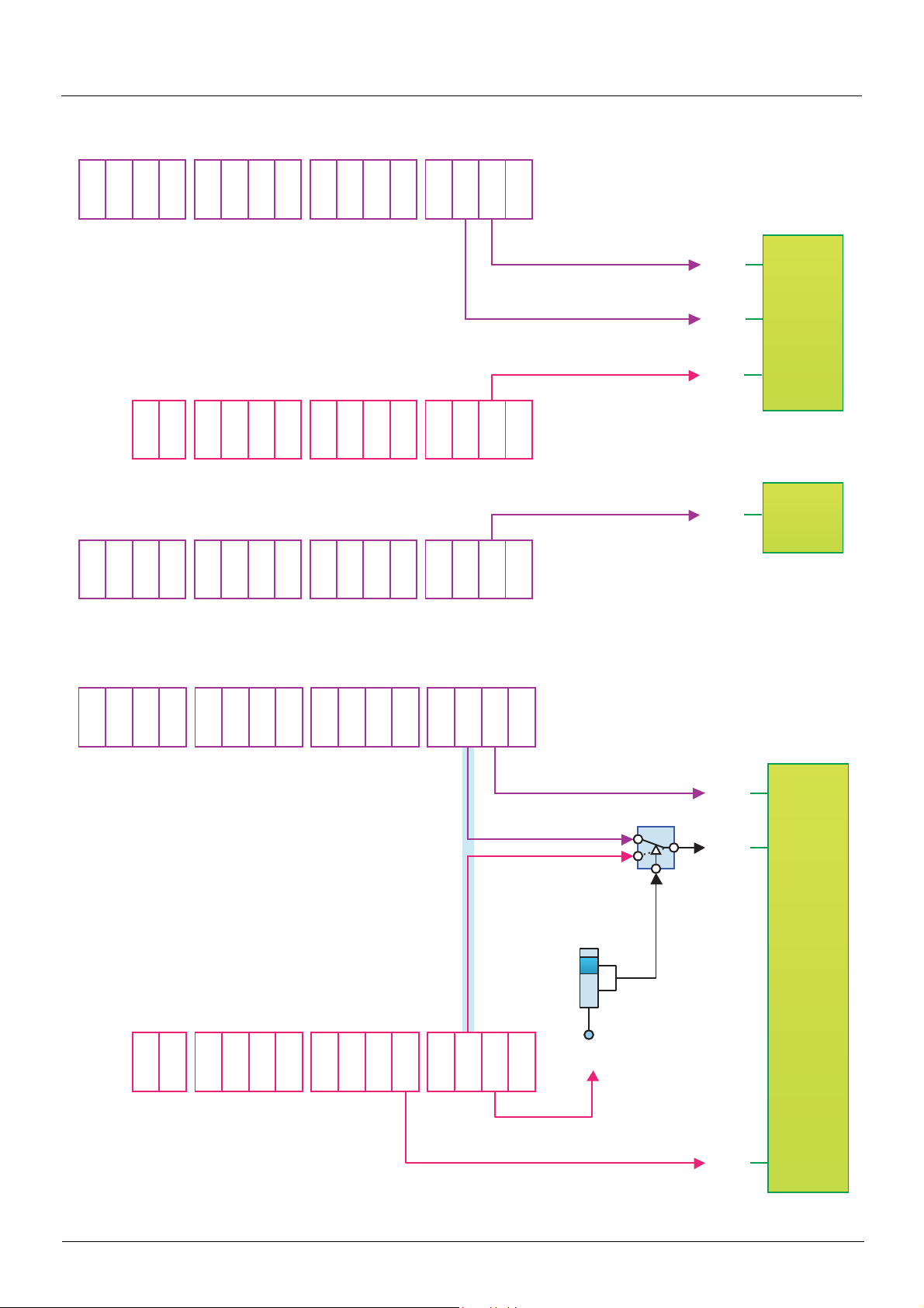
Control word - run on state [2 wire] (2C)
Please refer to the [1.5 INPUTS / OUTPUTS CFG] (I-O-) section of the Programming Manual.
The forward run command is automatically assigned to input LI1 and to bit 0 of the various control words.
This assignment cannot be modified.
The run command is active on state 1:
• Of input LI1, if the terminals are active
• Of bit 0 of the control word, if the network is active
Bits 1 to 15 of the control words can be assigned to drive functions.
bit 7 bit 6 bit 5 bit 4 bit 3 bit 2 bit 1 bit 0
Configurable Configurable Configurable Configurable Configurable Configurable Configurable Forward
bit 15 bit 14 bit 13 bit 12 bit 11 bit 10 bit 9 bit 8
Configurable Configurable Configurable Configurable Configurable Configurable Configurable Configurable
In the case of a [2 wire] (2C) run on state command and I/O profile, fixed assignment of a function input is possible using the following
codes:
Fixed assignments
Bit
Drive terminals Logic I/O card
bit 0 Forward
bit 1 LI2 - - C101 C201 C301 C401
bit 2 LI3 - - C102 C202 C302 C402
bit 3 LI4 - - C103 C203 C303 C403
bit 4 LI5 - - C104 C204 C304 C404
bit 5 LI6 - - C105 C205 C305 C405
bit 6 - LI7 - C106 C206 C306 C406
bit 7 - LI8 - C107 C207 C307 C407
bit 8 - LI9 - C108 C208 C308 C408
bit 9 - LI10 - C109 C209 C309 C409
bit10 - - LI11 C110 C210 C310 C410
bit11 - - LI12 C111 C211 C311 C411
bit12 - - LI13 C112 C212 C312 C412
bit13 - - LI14 C113 C213 C313 C413
bit14 - - - C114 C214 C314 C414
bit15 - - - C115 C215 C315 C415
Extended I/O
card
Modbus CANopen Network card
"Controller Inside"
card
For example, to assign the operating direction command to bit 1 of CANopen, simply conf igure the [Reverse ass ign.] (rrS) parameter with
the value [C201] (C201).
15
Page 16

I/O profile
Control word - run on edge [3 wire] (3C)
Please refer to the [1.5 INPUTS / OUTPUTS CFG] (I-O-) section of the Programming Manual.
The stop command is automatically assigned to input LI1 and to bit 0 of the control words.
This assignment cannot be modified.
This command enables running on state 1:
• Of input LI1, if the terminals are active
• Of bit 0 of the control word, if the network is active
The forward run command is automatically assigned to input LI2 and to bit 1 of the control words.
This assignment cannot be modified.
The forward run command is active if the stop command is at 1 and on a rising edge (0 V 1):
• Of input LI2, if the terminals are active
• Of bit 1 of the control word, if the network is active
Bits 2 to 15 of the control words can be assigned to drive functions.
bit 7 bit 6 bit 5 bit 4 bit 3 bit 2 bit 1 bit 0
Configurable Configurable Configurable Configurable Configurable Configurable Forward Stop
bit 15 bit 14 bit 13 bit 12 bit 11 bit 10 bit 9 bit 8
Configurable Configurable Configurable Configurable Configurable Configurable Configurable Configurable
In the case of a [3 wire] (3C) run on state command and I/O profile, fixed assignment of a function input is possible using the following
codes:
Fixed assignments
Bit
Drive terminals Logic I/O card
bit 0 Authorization to run (Stop)
bit 1 Forward
bit 2 LI3 - - C102 C202 C302 C402
bit 3 LI4 - - C103 C203 C303 C403
bit 4 LI5 - - C104 C204 C304 C404
bit 5 LI6 - - C105 C205 C305 C405
bit 6 - LI7 - C106 C206 C306 C406
bit 7 - LI8 - C107 C207 C307 C407
bit 8 - LI9 - C108 C208 C308 C408
bit 9 - LI10 - C109 C209 C309 C409
bit10 - - LI11 C110 C210 C310 C410
bit11 - - LI12 C111 C211 C311 C411
bit12 - - LI13 C112 C212 C312 C412
bit13 - - LI14 C113 C213 C313 C413
bit14 - - - C114 C214 C314 C414
bit15 - - - C115 C215 C315 C415
Extended I/O
card
Modbus CANopen Network card
"Controller Inside"
card
For example, to assign the operating direction command to bit 2 of CANopen, simply conf igure the [Reverse ass ign.] (rrS) parameter with
the value [C202] (C202).
16
Page 17

I/O profile
Status word (ETA)
bit 7 bit 6 bit 5 bit 4 bit 3 bit 2 bit 1 bit 0
Alarm
bit 15 bit 14 bit 13 bit 12 bit 11 bit 10 bit 9 bit 8
Direction of
rotation
The status word is identical in the I/O profile and the CiA402 profile. For more detailed information, refer to section “CiA402 profile”, page 18.
Reserved
(= 0 or 1)
Stop via STOP
key
Reserved (= 1)
Reserved (= 0) Reserved (= 0)
Power section
line supply
present
Fault Running Ready
Reference
outside limits
Reference
reached
Command or
reference via
network
Reserved
(= 0 or 1)
Reserved (= 0)
17
Page 18

CiA402 profile
Functional description
b The operation of the drive can be summarized by 2 main functions, described by the foll owing 2 diagrams (the values i n brackets are the
CANopen addresses of the parameters):
• Control diagram:
controlword
(6040)
State machine
statusword
(6041)
• Simplified diagram of the speed control in "Velocity" mode:
vl_target_velocity
(6042)
Limit Ramp
vl_velocity_demand
(6043)
Power
device
3
M
vl_velocity_min_max amount (6046)
b The main parameters are shown with their CiA402 name and their CiA402/Drivecom index (the values in brackets are the parameter
codes).
These diagrams translate as follows for the Altivar system:
vl_velocity_acceleration (6048)
vl_velocity_acceleration (6049)
vl_control_effort
(6044)
• Control diagram:
Control word
(CMD)
State machine
Status word
(ETA)
• Simplified diagram of the speed regulation in "Velocity" mode:
Speed reference
(LFRD)
Reference limit Ramp
Acceleration - Speed delta (SPAL)
Minimum speed (SMIL)
Maximum speed (SMAL)
Acceleration - Time delta (SPAT)
Deceleration - Speed delta (SPDL)
Deceleration - Time delta (SPDT)
Speed reference
after ramp
(FRHD)
Power
module
3
Output speed
(RFRD)
M
18
Page 19

CiA402 profile
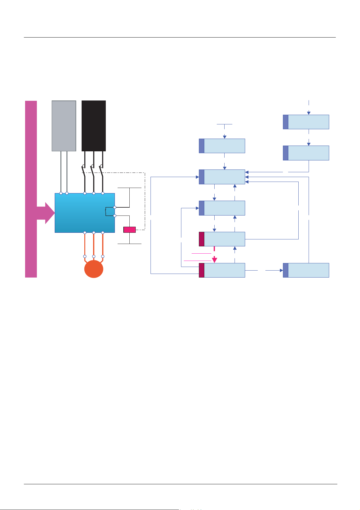
CiA402 state chart
Power section line supply present or absent
Entry into
state chart
Not ready to switch on
Switch on disabled
or
Disable voltage
CMD=16#0000
or
STOP key
or
freewheel stop at
the terminals
or
Power Removal
Shutdown
CMD=16#0006
Ready to switch on
or
Disable
voltage
CMD=16#0000
or
Quick stop
CMD=16#0002
or
STOP key
Fault disappeared
and faults reset
CMD=16#0080
Disable
voltage
CMD=16#0000
or
Quick stop
CMD=16#0002
or
STOP key
or
freewheel stop
at the terminals
or
modification
of a configuration
parameter
Fault
From all states
Fault
Fault reaction active
Fault
If Quick stop option code
= 2:
transition after stop.
If Quick stop option code
= 6:
Disable voltage
CMD=16#0000
or
STOP key
or
freewheel stop at
the terminals
Shutdown
CMD=16#0006
Switch on
CMD=16#xxxF
Key:
Switch on
CMD=16#0007
Shutdown
CMD=16#0006
Switched on
Disable
Enable
operation
CMD=16#xxxF
operation
CMD=16#0007
or
fast stop
Operation enabled
Examples:
ETA=16#0637: Stop or forward, speed reached
ETA=16#8637: Stop or reverse, speed reached
ETA=16#0237: For w ar d, acce le ra ti ng or dece le r ati n g
ETA=16#8237: Reverse, accelerating or decelerating
Power section line supply present
State
Switched on
Value of
status word
Quick stop
CMD=16#0002
Quick stop active
AC power
absent
CMD=16#xxxF
Transition condition
with example of command
Enable
operation
State display on
graphic display terminal
AC power
present
AC power absent
or present
19
Page 20

CiA402 profile
Description of states
Each state represents an internal reaction by the drive.
This chart will change depending on whether the control word is sent (CMD) or an event occurs (a fault, for example).
The drive state can be identified by the value of the status word (ETA).
1 - Not ready to switch on
Initialization starts. This is a transient state invisible to the communication network.
2 - Switch on disabled
The drive is inactive.
The drive is locked, no power is supplied to the motor.
For a separate control section, it is not necessary to supply AC power to the power section.
For a separate control section with line contactor, the contac tor is not controlled.
The configuration and adjustment parameters can be modified.
3 - Ready to switch on
Awaiting power section line supply.
For a separate control section, it is not ne cessa ry to s uppl y AC power to the p ower sec tion, b ut the sy ste m wil l expe ct it i n o rder to chan ge
to state "4
For a separate control section with line contactor, the contac tor is not controlled.
- Switch on".
The drive is locked, no power is supplied to the motor.
The configuration and adjustment parameters can be modified.
4 - Switched on
The drive is supplied with AC power but is stationary.
For a separate control section, the power section line supply must be present.
For a separate control section with line contactor, the contac tor is controlled.
The drive is locked, no power is supplied to the motor.
The power stage of the drive is ready to operate, but voltage has not yet been applied to the output.
The adjustment parameters can be modified.
Modification of a configuration parameter returns the drive to state "2 - Switch on disabled".
5 - Operation enabled
The drive is running.
For a separate control section, the power section line supply must be present.
For a separate control section with line contactor, the contac tor is controlled.
The drive is unlocked, power is supplied to the motor.
The drive functions are activated and voltage is applied to the motor terminals.
However, in the case of an open-loop drive, if the reference is zero or the "Halt" command i s applied, no power is suppli ed to the motor and
no torque is applied.
Auto-tuning (tUn) requires an injection of current into the motor. The drive must therefore be in state "5 - Operation enabled" for this
command.
The adjustment parameters can be modified.
The configuration parameters cannot be modified.
Note: The "4 - Enable operation" command must be taken into consideration only when the channel is valid (see Communication
monitoring page 51). In particular, if the channel is involved in the command and the reference, transiti on 4 will take place only after
the reference has been received for the first time.
The reaction of the drive to a "Disable operation" command depends on the value of the "Disable operation opti on code" (DOTD) parameter:
• If the "Disable operation option code" parameter has the value 0, the drive goes to "4 - Switched on" and stops in freewheel stop
• If the "Disable operation option code" parameter has the value 1, the drive stop s on ramp and then goes to "4 - Switched on"
20
Page 21

CiA402 profile
6 - Quick stop active
Emergency stop
The drive performs a fast stop, after which restarting will only be possible once the drive has changed to the "Switch on disabled" state.
During fast stop, the drive is unlocked and power is supplied to the motor.
The configuration parameters cannot be modified.
The condition for transition 12 to the state "2 - Switc h on disabled" depends on the value of the parameter "Quick st op option code" (QSTD):
• If the "Quick stop option code" parameter has the value 2, the dri ve stops according to t he fast stop ramp and then goes into the stat e
"2 - Switch on disabled".
• If the "Quick stop option code" parameter has the value 6, the drive stops according to the fast stop ramp and then remains in the
state "6 - Quick stop active" until:
- A "Disable voltage" command is received
- Or the STOP key is pressed
- Or there is a freewheel stop command via the terminals
7 - Fault reaction active
Transient state during which the drive performs an action appropriate to the type of fault.
The drive function is activated or deactivated according t o the type of reaction configured in the fault management parameters.
8 - Fault
Drive faulty.
The drive is locked, no power is supplied to the motor.
Summary
State
1 - Not ready to switch on Not required No Yes
2 - Switch on disabled Not required No Yes
3 - Ready to switch on Not required No Yes
4 - Switched on Required No
5 - Operation enabled Required
6 - Quick stop active Required Yes, during fast stop No
7 - Fault reaction active
8 - Fault Not required No Yes
Power section line supply for
separate control section
Depends on fault management
configuration
Power supplied to motor
Yes, apart from an open-loop
drive with a zero reference or in
the event of a "Halt" command
for an open-loop drive.
Depends on fault management
configuration
Modification of configuration
Yes, return to "2 - Switch on
disabled" state
parameters
No
-
21
Page 22

CiA402 profile
Control word (CMD)
bit 7 bit 6 bit 5 bit 4 bit 3 bit 2 bit 1 bit 0
Fault reset
Reserved (= 0)Reserved (= 0)Reserved (=
Ack. fault
Assignable Assignable Assignable Assignable
bit 15 bit 14 bit 13 bit 12 bit 11 bit 10 bit 9 bit 8
0)
Enable operation
Run command
By default,
direction of
rotation
command.
Quick stop Enable voltage
Emergency
stop
Reserved (= 0) Reserved (= 0)
Authorization
to supply AC
power
Switch on
Contactor
control
Halt
Halt
Command
Shutdown 2, 6, 8
Switch on 3 4 - Switched on x x 1 1 1 16#0007
Enable
operation
Disable
operation
Disable voltage 7, 9, 10, 12
Quick stop
Fault reset 15
x: Value is of no significance for this command.
0 V 1: Command on rising edge
Transition
address
4
5 4 - Swit c h ed on x 0 1 1 1 16#0007
11
7, 10
Final state
3 - Ready to
switch on
5 - Operation
enabled
2 - Switch on
disabled
6 - Quick stop
active
2 - Switch on
disabled
2 - Switch on
disabled
bit 7 bit 3 bit 2 bit 1 bit 0
Fault
reset
x x 1 1 0 16#0006
x 1 1 1 1 16#000F
x x x 0 x 16#0000
x x 0 1 x 16#0002
0 V 1 x x x x 16#0080
Enable
operation
Quick
stop
Enable
voltage
Switch on
Example value
22
Page 23

CiA402 profile
Stop commands:
The "Halt" command enables movement to be int errupted wi t hout ha vin g t o leave t he "5 - Operat ion ena bl ed" stat e. The st op is performed
in accordance with the [Type of stop] (Stt) parameter.
In the case of an open-loop drive, if the "Halt" command is active, no power is supplied to the motor and no torque is applied.
In the case of a closed-loop drive, if the "Halt" command is active , power c ontinues t o be supplie d to the motor and t orque is appl ied during
stopping.
Regardless of the assignment of the [Type of stop] (Stt) parameter ([Fast stop] (FSt), [Ramp stop] (rMP), [Freewheel] (nSt), [DC injection]
(dCI)), the drive remains in the "5 - Operation enabled" state.
A Fast Stop command at the terminals or using a bit of the control word assigned to Fast Stop causes a change to the "4 - Switched on"
state. A "Halt" command does not cause this transition.
A Freewheel Stop command at the terminals or using a bit of the control word assigned to Freewheel Stop causes a change to the "2 Switch on disabled" state.
WARNING
RISK OF EQUIPMENT DAMAGE
When the braking loop is configured, it is necessary to use the "Halt" command (bit 8 of CMD command word) to stop.
Failure to follow these instructions can result in death, serious injury or equipme nt damage.
Assigning control word bits
In the CiA402 profile, fixed assignment of a function input is po ssible using the following codes:
Bit Integrated Modbus CANopen Network card "Controller Inside" card
bit 11 C111 C211 C311 C411
bit 12 C112 C212 C312 C412
bit 13 C113 C213 C313 C413
bit 14 C114 C214 C314 C414
bit 15 C115 C215 C315 C415
For example, to assign the DC injection braking to bit 13 of CANopen, simply configure the [DC injection assign.] (dCI) parameter with
the [C213] (C213) value.
Bit 11 is assigned by default to the operating direction command [Reverse assign.] (rrS).
23
Page 24

CiA402 profile
Status word (ETA)
bit 7 bit 6 bit 5 bit 4 bit 3 bit 2 bit 1 bit 0
Warning
Alarm
bit 15 bit 14 bit 13 bit 12 bit 11 bit 10 bit 9 bit 8
Direction of
rotation
Switch on
disabled
Power section
line supply
disabled
Stop via
STOP key
Quick stop
Emergency
stop
Reserved (= 0)Reserved (=
Voltage
enabled
Power section
line supply
present
0)
Fault
Fault
Internal limit
active
Reference
outside limits
Operation
enabled
Running Ready
Target
reached
Reference
reached
Switched on
Remote
Command or
reference via
network
Ready to
switch on
Awaiting
power section
line supply
Reserved (= 0)
bit 6 bit 5 bit 4 bit 3 bit 2 bit 1 bit 0
Status
1 -Not ready to
switch on
2 -Switch on
disabled
3 -Ready to
switch on
4 -Switched on 0 1 1 0 0 1 1 16#0023
5 -Operation
enabled
6 -Quick stop
active
7 - Fault reaction
active
8 -Fault 0 x x 1 0 0 0
x: In this state, the value of the bit can be 0 or 1.
(1)
This mask can be used by the PLC program to test the chart state.
Switch on
disabled
0 x x 0 0 0 0 -
1 x x 0 0 0 0 16#0040
0 1 x 0 0 0 1 16#0021
0 1 1 0 1 1 1 16#0027
0 0 1 0 1 1 1 16#0007
0 x x 1 1 1 1 -
Quick
stop
Voltage
enabled
Fault
Operation
enabled
Switched onReady to
switch on
ETA
masked by
16#006F
16#0008
or 16#0028
(1)
(2)
(2)
Fault following state "6 - Quick stop active".
24
Page 25

CiA402 profile
Starting sequence
The command sequence in the state chart depends on how power is being supplied to the drive.
There are three possible s cen a r io s :
Power section
line supply
Control section
power supply
line supply
Power section
power supply
Control section
line supply
Power section
power supply
Control section
DRIVE DRIVE DRIVE
M MM M
Line contactor
Direct
Not separate
(1)
Direct
Separate
line supply
Power section
controlled
by the drive
Separate
(1)
The power section supplies the control section.
25
Page 26

CiA402 profile
Sequence for a drive powered by the power section line supply
Both the power and control sections are powered by the power section line supply.
If power is supplied to the control section, it has to be supplied to the power section as well.
The following sequence must be applied:
b Step 1
• Send the "2 - Shutdown" command
From all states
13
Bus or network
DRIVE
Power section
M
line supply
Disable
9
voltage
Shutdown
Entry into state chart
1
2
Shutdown
3
Switch on
8
4
Enable
operation
5 6
0
Not ready to
switch on
1
Switch on
disabled
2
Ready to
switch on
3
Switched on
4
Operation
enabled
7
6
5
Disable voltage
or Quick stop
Disable voltage
or Quick stop
Shutdown
Disable
operation
11
Quick stop
Fault reaction
7
8
15
active
Fault
10
Quick stop
active
14
12
26
Page 27
CiA402 profile
b Step 2
• Check that the drive is in the "3 - Ready to switch on" state.
• Then send the "4 - Enable operation" command.
• The motor can be controlled (send a reference not equal to zero).
From all states
13
Bus or network
DRIVE
line supply
Power section
M
Disable
9
voltage
Shutdown
1
2
Switch on
3
Switch on
8
4
Enable
operation
5
Entry into state chart
0
Not ready to
switch on
1
Switch on
disabled
2
Ready to
switch on
3
Switched on
4
Operation
enabled
Disable voltage
7
or Quick stop
6
Shutdown
Disable
5
operation
Disable voltage
or Quick stop
11
Quick stop
Fault reaction
7
8
15
6
active
10
Quick stop
active
14
Fault
12
Note: It is possible, but not necessary, to send the "3 - Switch on" command and then the "4 - Enable Operation" command to go
successively into the states "3
The "4 - Enable operation" command is sufficient.
- Ready to Switch on", "4 - Switched on" and then "5 - Operation Enabled".
27
Page 28

CiA402 profile
Sequence for a drive with separate control section
Power is supplied separately to the power and control sections.
If power is supplied to the control section, it does not have to be supplied to the power section as well.
The following sequence must be applied:
b Step 1
• The power section line supply is not necessarily present.
• Send the "2 - Shutdown" command.
From all states
13
power supply
Control section
Bus or network
DRIVE
Power section
M
line supply
Disable
9
voltage
Shutdown
1
2
Shutdown
3
Switch on
8
4
Enable
operation
5 6
Entry into state chart
0
Not ready to
switch on
1
Switch on
disabled
2
Ready to
switch on
3
Switched on
4
Operation
enabled
Disable voltage
7
or Quick stop
Shutdown
6
Disable
5
operation
Disable voltage
or Quick stop
11
Quick stop
Fault reaction
7
8
15
10
Quick stop
active
14
Fault
12
active
28
Page 29

CiA402 profile
b Step 2
• Check that the drive is in the "3 - Ready to switch on" state.
• Check that the power section line supply is present ("Voltage enabled" of the status word).
Power section line supply Terminal display Status word
Absent nLP 16#pp21
Present rdY 16#pp31
• Send the "3 - Switch on" command.
From all states
13
power supply
Control section
Bus or network
DRIVE
Power section
M
line supply
Disable
9
voltage
Shutdown
Entry into state chart
0
Not ready to
1
switch on
1
Switch on
2
disabled
Shutdown Disable voltage
Switch on
8
Enable
operation
2
Ready to
3
switch on
3
Switched on
4
4
Operation
5 6
enabled
7
or Quick stop
6
Shutdown
Disable
5
operation
Disable voltage
or Quick stop
11
Quick stop
Fault reaction
7
8
15
active
10
Quick stop
active
14
Fault
12
29
Page 30
CiA402 profile
b Step 3
• Check that the drive is in the "4 - Switched on" state.
• Then send the "4 - Enable operation" command.
• The motor can be controlled (send a reference not equal to zero).
• If the power section line supply is still not pre sent in the "4 - Switched on" st ate after a t ime delay [Mains V. time out] (LCt), the drive
will switch to fault mode (LCF).
From all states
13
Bus or network
Control section
power supply
DRIVE
Power section
M
line supply
Disable
9
voltage
Shutdown
Entry into state chart
0
Not ready to
1
switch on
1
Switch on
2
disabled
Shutdown Disable voltage
Switch on
8
Enable
operation
2
Ready to
3
switch on
3
Switched on
4
4
Operation
5 6
enabled
7
or Quick stop
6
Shutdown
Disable
5
operation
Quick stop
7
8
15
Disable voltage
or Quick stop
11
Fault reaction
active
14
Fault
10
12
Quick stop
active
30
Page 31

CiA402 profile
Sequence for a drive with line contactor control
Power is supplied separately to the power and control sections.
If power is supplied to the control section, it does not have to be supplied to the power secti on as well. The drive controls the line contactor.
The following sequence must be applied:
b Step 1
• The power section line supply is not present as the line contactor is not being controlled.
• Send the "2 - Shutdown" command.
From all states
13
power supply
Control section
DRIVE
Bus or network
Power section
M
line supply
Disable
9
voltage
Shutdown
Entry into state chart
1
2
Shutdown
3
Switch on
8
4
Enable
operation
5 6
0
Not ready to
switch on
1
Switch on
disabled
2
7
Ready to
switch on
3
6
Switched on
4
5
Operation
enabled
Disable voltage
or Quick stop
Disable voltage
or Quick stop
Shutdown
Disable
operation
11
Quick stop
Fault reaction
7
active
8
15
Fault
10
Quick stop
active
14
12
31
Page 32

CiA402 profile
b Step 2
• Check that the drive is in the "3 - Ready to switch on" state.
• Send the "3 - Switch on" command, which will close the line contactor and switch on the power section line supply.
From all states
13
Bus or network
power supply
Control section
DRIVE
line supply
Power section
M
Disable
9
voltage
Shutdown
Entry into state chart
Not ready to
1
switch on
Switch on
2
Shutdown
3
switch on
Switch on
Switched on
8
4
Enable
operation
Operation
5 6
0
1
disabled
2
Ready to
3
4
enabled
Disable voltage
7
or Quick stop
Disable voltage
6
Shutdown
Disable
5
operation
11
Quick stop
7
8
15
or Quick stop
Fault reaction
active
14
Fault
10
12
Quick stop
active
32
Page 33
CiA402 profile
b Step 3
• Check that the drive is in the "4 - Switched on" state.
• Then send the "4 - Enable operation" command.
• The motor can be controlled (send a reference not equal to zero).
• If the power section line supply is still not present in the "4 - Switched on" state after a time delay[Mains V. time out] (LCt), the drive
will switch to fault mode (LCF).
From all states
13
Bus or network
power supply
Control section
DRIVE
Power section
M
Entry into state chart
0
line supply
Shutdown
Disable
9
voltage
Shutdown
Switch on
8
operation
Not ready to
1
switch on
1
Switch on
2
disabled
2
Ready to
3
switch on
3
4
Switched on
Enable
4
Operation
5 6
enabled
Disable voltage
7
or Quick stop
Disable voltage
Shutdown
6
Disable
5
operation
11
Quick stop
or Quick stop
Fault reaction
7
active
Fault
8
15
10
Quick stop
active
14
12
33
Page 34

Command/reference switching
Channels
A channel is the name given to the source of a command or reference.
The six Altivar 61 channels are:
• The terminals
• The graphic display terminal
• The integrated Modbus ports
• The integrated CANopen port
• A network card
• The "Controller Inside" card
The Altivar 61 has two integrated Modbus ports. The se two ports are physical ly independent of one another but together constit ute a singl e
logic channel.
The drive does not distinguish between commands and references that come from the Modb us network port and tho se that come from the
Modbus HMI port.
With the Altivar 61 drive, it is possible to select the active command channel and the active reference channel:
• Via configuration
• Via switching at the terminals or via a communication network
Channel commands and references
All the drive’s command and reference parameters are managed on a channel-by-channel basis.
Only the control word (CMd), speed reference (LFrd) and frequency reference (LFr) are switched.
It is possible to identify the last value written for each channel and each command or reference parameter:
Parameter name Parameter code
Taken into
account by the
drive
Control word CMd CMd1 CMd2 CMd3 CMd4
Extended control word CMI CMI1 CMI2 CMI3 CMI4
Speed reference (rpm) LFrd LFd1 LFd2 LFd3 LFd4
Frequency reference (0.1 Hz) LFr LFr1 LFr2 LFr3 LFr4
PID regulator reference PISP PIr1 PIr2 PIr3 PIr4
Analog multiplier reference MFr MFr1 MFr2 MFr3 MFr4
Modbus CANopen
Communication
card
Controller Inside
34
Page 35
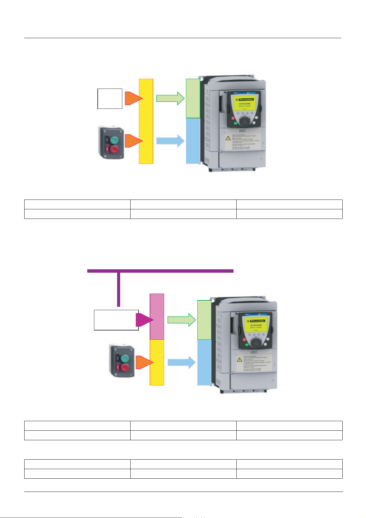
Command/reference switching
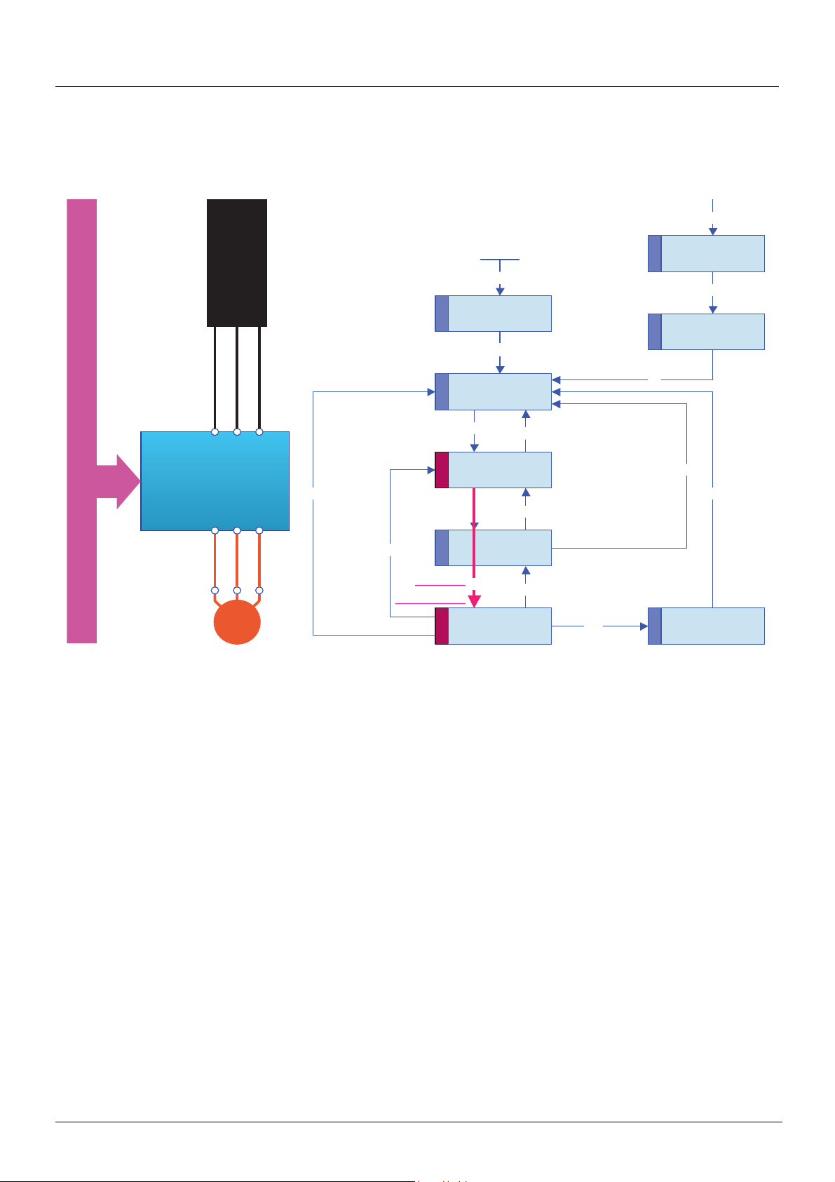
Not separate mode
Command and reference come from the same channel.
-10V
+10V
TERMINALS
In CiA402 profile, the not separate mode is configured via the terminal:
ReferenceCommand
Menu Parameter Value
[1.6 - COMMAND] (CtL-) [Profile] (CHCF) [Not separ.] (SIM)
Separate mode
Command and reference may come from different channels.
CANopen
Digital
reference
CANopen
ReferenceCommand
TERMINALS
In CiA402 profile, the separate mode is achieved via configuration with the terminal:
Menu Parameter Value
[1.6 - COMMAND] (CtL-) [Profile] (CHCF) [Separate] (SEP)
In I/O profile, the drive is automatically in separate mode.
Menu Parameter Value
[1.6 - COMMAND] (CtL-) [Profile] (CHCF) [I/O profile] (IO)
35
Page 36

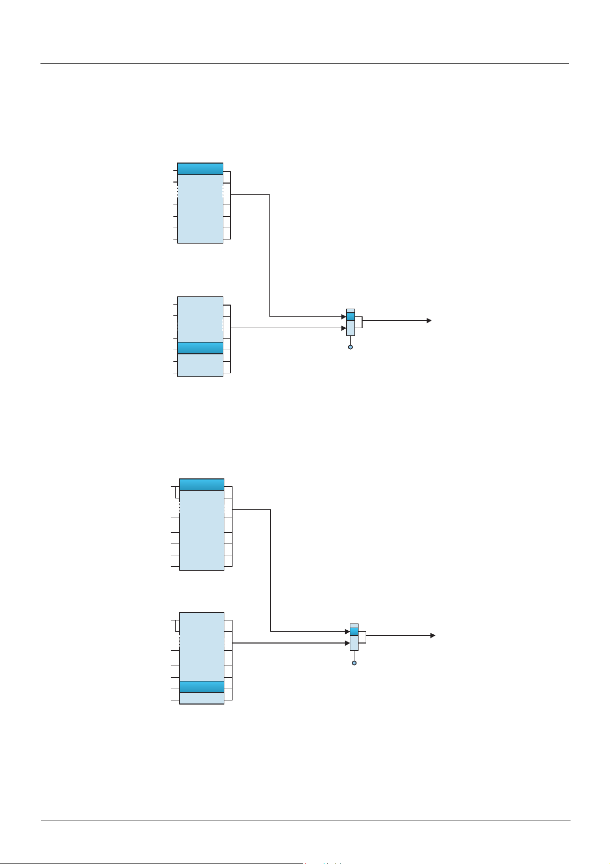
Command/reference switching
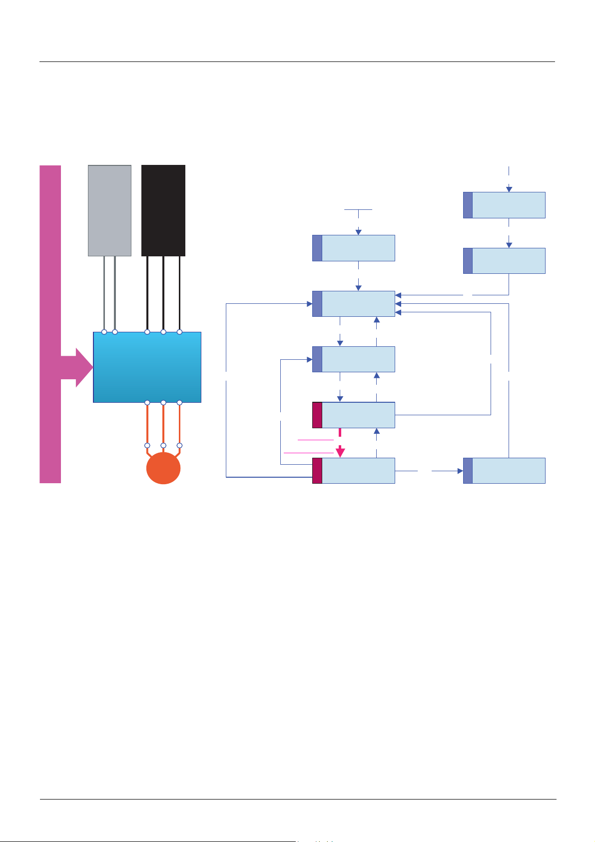
Switching in not separate mode
Switching takes place between 2 channels simultaneously for both reference and command.
CANopen
Control register
Digital reference
CANopen
-10V
+10v
ReferenceCommand
TERMINALS
In this example, the command and reference come either from CANopen or from the terminals.
Switching in separate mode
Switching can take place between 2 channels independently for the reference and command.
-10V
+10V
CANopen
Digital reference
CANopen
ReferenceCommand
TERMINALS
In this example, the command always comes from the terminals; the reference can come either from CANopen or from the terminals.
36
Page 37

Command/reference switching
Channel switching
Reference channel configuration
Reference channel configuration enables reference sources to be predefined, which can be modified or switched subsequently via a
command.
There are 3 predefined reference channels:
• Reference channel 1
• Reference channel 1B
• Reference channel 2
Reference channels 1 and 1B are used for drive application functions.
Reference channel 2 is connected directly to the reference limiting function, bypassing the application functions.
The predefined reference channels are assigned via the [Ref.1 channel] (Fr1), [Ref.1B channel] (Fr1b) and [Ref.2 channel] (Fr2)
configuration parameters, which can have the following values:
• [No] (nO): Not assigned
• [AI1] (AI1): Analog input AI1
• [AI2] (AI2): Analog input AI2
• [AI3] (AI3): Analog input AI3 (if extension card present)
• [AI4] (AI4): Analog input AI4 (if extension card inserted)
• [HMI] (LCC): Graphic display terminal
• [Modbus] (Mdb): Integrated Modbus
• [CANopen] (CAn): Integrated CANopen
• [Com. card] (nEt): Communication card (if inserted)
• [C.Insid. card] (APP): Controller Inside card (if inserted)
• [RP] (PI): Frequency input (if card inserted)
• [Encoder] (PG): Encoder input (if card inserted)
Note: The "+speed/-speed" function is on reference channel 2. See the Programming Manual for more information.
Command channel configuration
Command channel configuration enables command sources to be predefined, which can be modified or switched subsequently via a
command.
There are 2 predefined reference channels:
• Command channel 1
• Command channel 2
The predefined command channels are assigned via the [Cmd channel 1] (Cd1) and [Cmd channel 2] (Cd2) configuration parameters,
which can have the following values:
• [Terminals] (tEr): Terminals
• [HMI] (LCC): Graphic display terminal
• [Modbus] (Mdb): Integrated Modbus
• [CANopen] (CAn): Integrated CANopen
• [Com. card] (nEt): Communication card (if inserted)
• [C.Insid. card] (APP): Controller Inside card (if inserted)
37
Page 38

Command/reference switching
Switches
A channel switch is used to select predefined channels.
It can be:
• Defined via configuration
• Activated either via an input (terminals) or a control word bit (network)
• Written via a network during operation (modification of a configuration parameter)
The possible switch values are:
Function reference
switching
[Ref 1B switching] (rCb)
Channel 1 Fr1 Fr1 Cd1
Channel 1B Fr1b
Channel 2 - Fr2 Cd2
Drive input LI1 ... LI6
Logic I/O card input LI7 ... LI10
Extended I/O card input LI11 ... LI14
Modbus command bit bit 0 = C100 ... bit 15 = C115
CANopen command bit bit 0 = C200 ... bit 15 = C215
Network command bit bit 0 = C300 ... bit 15 = C315
Controller Inside command bit bit 0 = C400 ... bit 15 = C415
The values Fr1, Fr1b, Fr2, Cd1 and Cd2 are either configured or written via the network during operation.
In I/O and CiA402 profiles (separate), independent switching is possible:
Type Channel 1 Channel 2 Switching
Reference
Command
Function reference 1
[Ref.1 channel] (Fr1)
Function reference 1 or 1B
[Ref.1 channel] (Fr1)
[Ref.1B channel] (Fr1b)
Command 1
[Cmd channel 1] (Cd1)
Function reference 1B
V
V
[Ref.1B channel] (Fr1b)
Direct reference 2
V
V
[Ref.2 channel] (Fr2)
Command 2
V
V
[Cmd channel 2] (Cd2)
Direct reference switching
[Ref. 2 switching] (rFC)
- -
Function reference switching
[Ref 1B switching] (rCb)
Direct reference switching
[Ref. 2 switching] (rFC)
Command switching
[Cmd switching] (CCS)
Command switching
[Cmd switching] (CCS)
In CiA402 profile (not separate), switching is simultaneous:
Type Channel 1 Channel 2 Switching
Reference
and
Command
38
Function reference 1 or 1B
[Ref.1 channel] (Fr1)
[Ref.1B channel] (Fr1b)
Command 1
[Cmd channel 1] (Cd1)
Direct reference 2
V
V
[Ref.2 channel] (Fr2)
Command 2
V
V
[Cmd channel 2] (Cd2)
Direct reference switching
[Ref. 2 switching] (rFC)
Page 39

Command/reference switching
A
A
A
A
A
A
A
A
Reference switching principle
A detailed description is given in the Programming Manual.
This diagram shows reference switching as applicable to all the following modes:
• I/O profile
• CiA402 profile and separate mode
• CiA402 profile and not separate mode
Reference channel 1
Fr1
Fr1
AI1
I1C
I1C
I2C
I2C AI2
LFr
LFr1
LFr2
LFr3
LFr4
I1C
I2C
LFr
LFr1
LFr2
LFr3
LFr4
I1C
I2C
LFr
LFr1
LFr2
LFr3
LFr4
AI1
AI2
Display terminal
TerminalLFr
Modbus
Modbus
CANopen
CANopen
Network
RØseau
Controller
Controller
Reference channel 1B
Fr1b
AI1
AI2
Display terminal
Modbus
CANopen
Network
Controller
Reference channel 2
Fr2
AI1
AI2
Display terminal
Modbus
CANopen
Network
Controller
Function
reference
switching
rCb
Fr1
Fr1b
LIpp
C1pp
C2pp
C3pp
C4pp
Function
Application
function
output
reference
Direct
reference 2
Direct
reference
switching
rFC
Fr1
Fr2
LIpp
C1pp
C2pp
C3pp
C4pp
Reference
limit
Ramp
39
Page 40
Command/reference switching
Command switching principle
A detailed description is given in the Programming Manual.
I/O profile or CiA402 profile (separate mode)
Command channel 1
Cd1
Terminals
LIx
RUN/STOP
FWD/REV
CMD1
CMD2
CMD3
Display
Terminal
terminal
Modbus
Modbus
CANopen
CANopen
RØseau
Network
ControllerCMD4
Command channel 2
Cd2
Terminals
LIx
Bornier
Display
RUN/STOP
FWD/REV
CMD1
CMD2
CMD3
Terminal
terminal
Modbus
CANopen
Network
ControllerCMD4
CiA402 profile (not separate mode)
Reference channel 1
Fr1
LIx
LIx
RUN/STOP
FWD/REV
CMD1
CMD2
CMD3
CMD4
AI1
AI2
Display
terminal
Modbus
CANopen
Network
Command
switching
CCS
Cd1
Cd2
LIpp
C1pp
C2pp
C3pp
C4pp
(1)
Run
Stop
Forward
Reverse
Direct
reference
switching
rFC
Fr1
Fr2
LIpp
C111 ... C115
C211 ... C215
C311 ... C315
C411 ... C415
(1)
Run
Stop
Forward
Reverse
LIx
RUN/STOP
FWD/REV
CMD1
CMD2
CMD3
CMD4
Reference channel 2
Fr2
AI1
AI2
Display
terminal
Modbus
CANopen
Network
(1)
(1)In not separate mode, command switching follows reference switching. It is therefore reference switching that switches the command.
40
Page 41

Command/reference switching
Assigning control word bits
I/O profile
The I/O profile is extremely flexible in terms of assigning and switching the 16 control word bits.
To switch a control word bit using:
• An input from the terminals
• Or a control word bit from another communication channel
simply configure a switched assignment for the function input (CDpp), instead of a fixed assignment (Cppp).
Inputs and bits of the same order are switched.
Inputs LI1 to LI6 of the drive terminals can be used to switch control word bits 0 to 5.
With a logic I/O card using inputs LI7 to LI10, control word bits 6 to 9 can also be switc hed.
With an extended I/O card using inputs LI11 to LI14, control word bits 10 to 13 can al so be switched.
Once a bit has been assigned to a switchable assignment, it can no longer be assigned to a fixed assignment, and vice versa.
Example: Once a function input has been assigned to CD04, it can not be assigned to LI5, C104, C204, C304 or C404.
Example
Function input A is always controlled by bit 1 of the CANopen control word.
Function input B is always controlled by input LI5 on the terminals.
Depending on the value of LI2, function input C is controlled:
• Either by input LI3 on the terminals
• Or by bit 2 of the CANopen control word
CANopen control word
bit 9
bit 8
bit 7
bit 6
bit 5
bit 4
bit 3
bit 2
bit 1
bit 1
bit 0
bit 0
C201
Cd02
Function
A
C
bit 11
bit 13
bit 15
bit 14
bit 12
bit 10
bit 2
Command
switching
CCS
CANopen
Terminals
Terminals
LI2
LI10
LI9
LI8
LI7
LI6
LI5
LI4
LI3
LI2
LI12
LI14
LI13
LI11
LI1
LI5
B
41
Page 42

Command/reference switching
The tables below show assignments on the basis of input or bit.
Run on state command [2 wire] (2C):
Fixed assignments
Switched
assignmen
Bit
t
bit 0 Forward
bit 1 Cd01 LI2 - - C101 C201 C301 C401
bit 2 Cd02 LI3 - - C102 C202 C302 C402
bit 3 Cd03 LI4 - - C103 C203 C303 C403
bit 4 Cd04 LI5 - - C104 C204 C304 C404
bit 5 Cd05 LI6 - - C105 C205 C305 C405
bit 6 Cd06 - LI7 - C106 C206 C306 C406
bit 7 Cd07 - LI8 - C107 C207 C307 C407
bit 8 Cd08 - LI9 - C108 C208 C308 C408
bit 9 Cd09 - LI10 - C109 C209 C309 C409
bit10 Cd10 - - LI11 C110 C210 C310 C410
bit11 Cd11 - - LI12 C111 C211 C311 C411
bit12 Cd12 - - LI13 C112 C212 C312 C412
bit13 Cd13 - - LI14 C113 C213 C313 C413
bit14 Cd14 - - - C114 C214 C314 C414
bit15 Cd15 - - - C115 C215 C315 C415
Drive
terminals
Logic I/O card
Extended I/O
card
Integrated
Modbus
CANopen Network card
"Controller
Inside"
card
Run on edge command [3 wire] (3C):
Fixed assignments
Switched
assignmen
Bit
t
bit 0 Run authorization
bit 1 Forward
bit 2 Cd02 LI3 - - C102 C202 C302 C402
bit 3 Cd03 LI4 - - C103 C203 C303 C403
bit 4 Cd04 LI5 - - C104 C204 C304 C404
bit 5 Cd05 LI6 - - C105 C205 C305 C405
bit 6 Cd06 - LI7 - C106 C206 C306 C406
bit 7 Cd07 - LI8 - C107 C207 C307 C407
bit 8 Cd08 - LI9 - C108 C208 C308 C408
bit 9 Cd09 - LI10 - C109 C209 C309 C409
bit10 Cd10 - - LI11 C110 C210 C310 C410
bit11 Cd11 - - LI12 C111 C211 C311 C411
bit12 Cd12 - - LI13 C112 C212 C312 C412
bit13 Cd13 - - LI14 C113 C213 C313 C413
bit14 Cd14 - - - C114 C214 C314 C414
bit15 Cd15 - - - C115 C215 C315 C415
Drive
terminals
Logic I/O card
Extended I/O
card
Integrated
Modbus
CANopen Network card
"Controller
Inside"
card
42
Page 43

Command/reference switching
CiA402 profile
Control word bits of the same order are switched if the function inputs are assigned to swi tchable bits.
Switching may be poss ible using LI12, LI13 or LI14 on an extended I/O card.
Once a bit has been assigned to a switchable assignment, it can no longer be assigned to a fixed assignment, and vice versa.
Example: Once a function input has been assigned to Cd04, it c annot be assigned to LI5, C104, C204, C304 or C404.
The table below shows assignments on the basis of input or bit.
Fixed assignments
Switched
assignmen
Bit
t
bit 0 - LI1 - - - - - bit 1 - LI2 - - - - - bit 2 - LI3 - - - - - bit 3 - LI4 - - - - - bit 4 - LI5 - - - - - bit 5 - LI6 - - - - - bit 6 - - LI7 - - - - bit 7 - - LI8 - - - - bit 8 - - LI9 - - - - bit 9 - - LI10 - - - - bit10 - - - LI11 - - - bit11 Cd11 - - LI12 C111 C211 C311 C411
bit12 Cd12 - - LI13 C112 C212 C312 C412
bit13 Cd13 - - LI14 C113 C213 C313 C413
bit14 Cd14 - - - C114 C214 C314 C414
bit15 Cd15 - - - C115 C215 C315 C415
Drive
terminals
Logic I/O card
Extended I/O
card
Integrated
Modbus
CANopen Network card
"Controller
Inside"
card
43
Page 44

Command/reference switching
Copy on switching
When switching channels, it is possible to copy the re ference or command from function channel 1 to direct channel 2.
Menu Submenu
[1.6 COMMAND] (CtL-)
Parameter Possible values
[Copy channel 1 --> 2] No copy.
[No] (nO)
Copy reference
[Reference] (SP)
Copy command
[Command] (Cd)
Copy command and reference
[Cmd + ref.] (ALL)
If a copy is not made, the drive stops according to the configured stop type [Type of stop] (Stt) until the first command and reference are
received.
The reference before ramp (FrH) is copied unless the direct channel 2 reference is via +/- speed.
If the direct channel 2 reference is via +/- speed, the after ramp (rFr) reference is copied.
If the direct channel 2 command is via the terminals, the function channel 1 command is not copied even in pulse control (3-wire) [3 wire]
(3C).
If the direct channel 2 reference is via AI1, AI2, AI3, AI4, the encoder input or frequency input, the function channel 1 reference is not copied.
44
Page 45

Forced local mode
Definition
Forced local mode supports switching to the terminals or display terminal.
This function complements channel switching and makes it possible to make use of an existing function from the Altivar 58 range.
Forced local mode is only available in CiA402 profile, not in I/O profile.
All other communication takes priority over forced local mode.
Forced local mode can be configured via the display terminal:
Menu Submenu
[1.9 COMMUNICATION] (COM-) [FORCED LOCAL] (LCF-)
Parameter Possible values
Forced local switch
[Forced local assign.] (FLO)
Forced local channel
[Forced local Ref.] (FLOC)
Function inactive:
[No] (nO)
Assignment to a logic input LI1 ... LI14:
[LI1] (LI1) ... [LI14] (LI14)
Forced local mode is active when the input is at state 1.
Forced local on stop.
[No] (nO)
Assignment of the command to the terminals an d of the refe rence to one of th e analog inputs AI1
... AI4
[AI2 ref.] (AI2), [AI3 ref.] (AI3), [AI4 ref.] (AI4)
Assignment of the command to the terminals and of the reference to the frequenc y inpu t (if card
present)
[Pulse Input] (PI)
Assignment of the reference [HMI Frequency ref.] (LFr) and of the command
(RUN/STOP/FWD/REV buttons) to the graphic display terminal
[HMI] (LCC)
In "forced local" state:
• Any attempts to write the parameter via one of these channels is rejected (applies to command, reference and adjustment
parameters).
• However, the parameters can be read.
• The drive does not register a communication fault.
On exiting "forced local" mode:
• The drive copies the run commands, the direction and the forced local reference to the active channel (maintained).
• Monitoring of the active command and reference channels resumes followi ng a time delay [Time-out forc. local] (FLOt).
• Drive control only takes effect once the drive has received the reference and the command.
The time delay [Time-out forc. local] (FLOt) (default value = 10 s) can be configured via the remote graphic display terminal:
Menu Submenu Parameter
[1.9 COMMUNICATION] (COM-) [FORCED LOCAL] (LCF-) [Time-out forc. local] (FLOt)
45
Page 46

Forced local mode
Forced local mode and reference switching
A detailed description is given in the Programming Manual.
This diagram shows reference switching as applicable to the following modes:
• CiA402 profile and separate mode
• CiA402 profile and not separate mode
Reference channel 1
Fr1
AI1
AI1C
AI2C
LFr
LFr1
LFr2
LFr3
LFr4
AI1C
AI2C
LFr
LFr1
LFr2
LFr3
LFr4
AI1C
AI2C
LFr
LFr1
LFr2
LFr3
LFr4
AI1
AI2
AI2
Display terminal
Modbus
CANopen
Network
Controller
Reference channel 1B
Fr1B
AI1
AI2
Display terminal
Modbus
CANopen
Network
Controller
Reference channel 2
Fr2
AI1
AI2
Display terminal
Modbus
CANopen
Network
Controller
Function
reference
switching
rCB
Fr1
Fr1b
C111 ... C115
C211 ... C215
C311 ... C315
C411 ... C415
LIpp
Function
AI1C
AI2C
AI3C
AI4C
LFr
Application
function output
reference
Direct
reference 2
Forced local channel
C111 ... C115
C211 ... C215
C311 ... C315
C411 ... C415
FLOC
AI1
AI1
AI2
AI2
AI3
AI3
AI4
AI4
Display terminal
Direct reference
switching
rFC
Fr1
Fr2
LIpp
Forced local
switching FLO
LI1
...
LI14
Reference
limit
Ramp
46
Page 47

Forced local mode
Forced local mode and command switching
A detailed description is given in the Programming Manual.
CiA402 profile (separate mode)
Command channel 1
Cd1
LIx
RUN/STOP
FWD/REV
CMD1
CMD2
CMD3
CMD4
Terminals
Display terminal
Modbus
CANopen
Network
Controller
RUN/STOP
FWD/REV
Forced local channel
FLOC
LIx
AI1
AI2
AI3
AI4
Display terminal
LIx
RUN/STOP
FWD/REV
CMD1
CMD2
CMD3
CMD4
Command channel 2
Cd2
Terminals
Display terminal
Modbus
CANopen
Network
Controller
Command
switching
CCS
Cd1
Cd2
LIpp
C111 ... C115
C211 ... C215
C311 ... C315
C411 ... C415
Forced local
switching FLO
Run
Stop
Forward
Reverse
LI1 ... LI14
47
Page 48
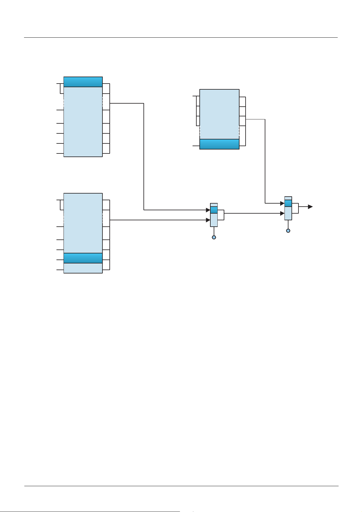
Forced local mode
CiA402 profile (not separate mode)
Reference channel 1 (1)
Fr1
LIx
LIx
RUN/STOP
FWD/REV
CMD1
CMD2
CMD3
CMD4
Reference channel 2 (1)
LIx
RUN/STOP
FWD/REV
CMD1
CMD2
CMD3
CMD4
AI1
AI2
Display terminal
Modbus
CANopen
Network
Controller
Fr2
AI1
AI2
Display terminal
Modbus
CANopen
Network
Controller
LIx
RUN/STOP
FWD/REV
C111 ... C115
C211 ... C215
C311 ... C315
C411 ... C415
Forced local channel
FLOC
AI1
AI2
AI3
AI4
Display terminal
Direct reference
switching
rFC
Fr1
Fr2
LIpp
Forced local
switching FLO
LI1
...
LI14
Run
Stop
Forward
Reverse
(1)In not separate mode, command switching follows reference switching. It is therefore reference switching that switches the command.
48
Page 49

Priority stops
Priority stops on the graphic display terminal
If the graphic display terminal is not the active command channel, pressing the STOP key on the graphic display terminal causes a
freewheel stop if:
• The
[Stop Key priority]
If the graphic display terminal is the active command channel, the STOP key causes a stop according to the type of stop configured in the
[Type of stop] (Stt) parameter, regardless of the value of the [Stop Key priority] (PSt) parameter.
The effect of the graphic display terminal does not depend on the profile.
Priority stops via the terminals or the network
I/O profile
In the I/O profile:
Stop and fault commands, configured as fixed assignments (LIpp, C1pp, C2pp, C3pp, C4pp), on terminal inputs or control word bits,
have priority even if the channel is not active.
Commands, configured as switched assignments (Cd00 ... Cd15), are active if and only if the channel is active.
(PSt) parameter in the
[1.6 - COMMAND]
(CtL-) menu is configured to
[Yes]
(YES) (factory setting).
Fixed assignments are configured by the following values:
Channel
Drive terminals LI2 ... LI6 LI3 ... LI6
Logic I/O card LI7 ... LI10
Extended I/O card LI11 ... LI14
Integrated Modbus C101 ... C115 C102 ... C115
CANopen C201 ... C215 C202 ... C215
Communication card C301 ... C315 C302 ... C315
"Controller Inside" card C401 ... C415 C402 ... C415
Command Configuration = 0 = 1 Value for starting
Freewheel stop [Freewheel stop ass.] (nSt) Stop No stop 1
Fast stop [Fast stop assign.] (FSt) Stop No stop 1
DC injection braking [DC injection assign.] (dCI) No braking Braking 0
External fault [External fault ass.] (EtF) No fault Fault 0
(1)
If the assignment is fixed, the value necessary for starting, even if another channel is active.
In run on edge command, configured by [3 wire] (3C):
The stop command (run enable) is assigned by construction to switched order 0 (equivalent to Cd00):
• It is active at the terminals (LI1) only if the terminals are active
• It is active via the network (bit 0) only if the network is active
Run on state command
[2 wire] (2C)
Run on edge command
[3 wire] (3C)
(1)
49
Page 50

Priority stops
CiA402 profile
In the CiA402 profile, separate or not separate mode:
External stop and fault commands, configured as fixed assig nments (LIpp, C1pp, C2pp, C3pp, C4pp), on terminal inputs or control word
bits, have priority even if the channel is not active.
Commands, configured as switched assignments (Cd11 ... Cd15), are active if and only if the channel is active.
Fixed assignments are configured by the following values:
Channel
Drive terminals LI2 ... LI6 LI3 ... LI6
Logic I/O card LI7 ... LI10
Extended I/O card LI11 ... LI14
Integrated Modbus C111 ... C115
CANopen C211 ... C215
Communication card C311 ... C315
"Controller Inside" card C411 ... C415
Cp11 is assigned by default to the reverse direction command [Reverse assign.] (rrS).
Run on state command
[2 wire] (2C)
Run on edge command
[3 wire] (3C)
At the terminals:
Command Configuration = 0 = 1
Freewheel stop
Fast stop [Fast stop assign.] (FSt) Stop No stop 1 4-Switched on
DC injection braking
External fault [External fault ass.] (EtF) No fault Fault 0 8-Fault
(1)
If the assignment is fixed, the value necessary for starting, even if another channel is active.
In run on edge command, configured by [3 wire] (3C), the stop command (run enable) is assigned by construction to LI1. This command
is active even if the terminals are not the active channel.
Via the network:
Command Configuration = 0 = 1
Fast stop [Fast stop assign.] (FSt) No stop Stop 0 4-Switched on
DC injection braking
External fault [External fault ass.] (EtF) No fault Fault 0 8-Fault
(1)
If the assignment is fixed, the value necessary for starting, even if another channel is active.
[Freewheel stop ass.]
(nSt)
[DC injection assign.]
(dCI)
[DC injection assign.]
(dCI)
Stop No stop 1 2-Switch on disabled
No braking Braking 0 5-Operation enabled
No braking Braking 0 5-Operation enabled
Value for
starting
Value for
starting
State reached from
(1)
5-Operation enabled
State reached from
(1)
5-Operation enabled
In the CiA402 profile, the freewheel stop comma nd [Freewheel stop ass.] (nSt) cannot be assigned to the control word. Freewheel stop is
obtained via the "5-Disable operation" or "Halt" command with the Type of Stop [Type of stop] (Stt) parameter configured t o [Freewheel]
(nSt).
50
Page 51

Communication monitoring
The Altivar 61 drive incorporates communication monitoring mechanisms.
Principle
Following initialization (power-up), the drive waits until at least one command or reference parameter has been written for the first time by
the network.
Then, the network is monitored and if a network fault occurs, the drive reacts according to the con figuration (ignore fault, stop on drive f ault,
speed maintenance, fallback speed, or stop without fault).
The drive can start only once all the command and reference parameters of the active network have been written.
Network monitoring criteria
The network is monitored in accordance with protocol-specific criteria, which are summarized in the table below and specified in the
corresponding protocol manual.
Protocol Network problem Related drive fault (1)
Integrated Modbus ports • Adjustable time-out for received requests destined for the drive [Modbus com.] (SLF1)
•Bus Off
• Life Guarding
Integrated CANopen port
Modbus TCP/IP Ethernet
card
Fipio card
Modbus Plus card
Modbus card
Uni-Telway card • Fixed time-out (10 s) for master polling
Profibus DP card
INTERBUS card
DeviceNet card
• CANoverrun
• Heartbeat
• NMT state machine transition
Network management fault:
• FDR fault
• IP address duplication fault
Communication fault:
• Adjustable time-out for received control word (I/O scanning or
messaging)
• Network overload
• Non-adjustable time-out for received periodic variables dest ined for
the drive
• Adjustable time-out:
• Either for received periodic variables (Peer cop) desti ned for the
drive
• Or for Modbus messages destined for the drive, if no periodic
variables (Peer cop) configured
• Fixed time-out (10 s) for received requests destined for the drive
• Adjustable time-out (via the network configuration software) for
received periodic variables (PZD and PKW) destined for the drive
• Time-out for received periodic variables destined for the drive
Communication fault:
• Adjustable time-out:
• Either for received periodic variables (Polling and COS)
destined for the drive
• Or for network activity, if no periodic variables configured
Configuration fault:
• The drive configuration is incompatible with the selected ass embl y
devices
[CANopen com.] (COF)
[External fault com.]
[Com. network] (CnF)
[External fault com.]
(EPF2)
(EPF2)
(1) If the drive is configured to trip on a fault in the event of a network fault.
If an anomaly is detected, the port or network card indicates a network fault.
51
Page 52

Communication monitoring
Behavior in the event of a network fault
In the event of a network fault (on a monitored channel), the drive reacts as specified in the
MANAGEMENT]
•
[Modbus fault mgt]
•
[CANopen fault mgt]
•
[Network fault mgt]
The Modbus TCP/IP Ethernet card can also trigger an external fault (in the event of an FDR fault or IP address duplication fault), to which
the drive reacts as specified in the
mgt]
(EPL) parameter.
The drive can react in five possible ways:
1. Drive fault
[Freewheel] (YES): Freewheel stop (factory setting)
[Ramp stop] (rMP):Stop on ramp
[Fast stop] (FSt): Fast stop
[DC injection] (dCI): DC injection stop
The fault displayed will depend on the source of the communication fault.
•
[Modbus com.]
•
[CANopen com.]
•
[Com. network]
•
[External fault com.]
The CiA402 state chart changes to "7 - Fault reaction active" and then to "8 - fault".
2. Stop without fault
(CLL-) submenu) by the following parameters:
(SLL) for integrated Modbus
(COL) for CANopen
(CLL) for a network card
[1.8 - FAULT MANAGEMENT]
(SLF1) for integrated Modbus
(COF) for CANopen
(CnF) for a network card
(EPF2) for Ethernet card FDR and IP faults
(FLt-) menu (
[1.8 - FAULT MANAGEMENT]
[EXTERNAL FAULT]
(EtF-) submenu) by the
(FLt-) menu (
[COM. FAULT
[External fault
[Per STT] (Stt): Stop according to configuration of [Type of stop] (Stt).
There is no drive fault.
If the CiA402 state chart is in "5 - Operation enabled", it changes to "4 - Switched on" after stopping.
3. Ignore fault
[Ignore] (nO): Fault ignored
4. Speed maintenance
[Spd maint.] (rLS): The drive maintains the speed at the time the fa ult occurred, as long as the fault persists and the run command has
not been removed.
There is no drive fault.
If the CiA402 state chart is in "5 - Operation enabled", it remains there.
5. Fallback speed
[Fallback spd] (LFF): Change to fallback speed, maintained as long as the fault persists and the run command has not been removed.
There is no drive fault.
If the CiA402 state chart is in "5 - Operation enabled", it remains there.
The fallback speed can be configured in the [1.8 - FAULT MANAGEMENT] (FLt-) menu using the [Fallback speed] (LFF) parameter.
Note: The drive will not start up immediately at the fallback speed. If there is a l oss of co mmuni cat ion, th e dri ve wi ll o nly run at th e f al lba ck
speed if the run command was present when the communication fault occurred.
In the event of a control system being used to ensure switchover to an act ive safe state if there is a loss of communicati on, drives that ha ve
been stopped must always be left in the run state (5 - Operation enabled) with zero reference to ensure that they change to the fallback
speed.
52
Page 53

Communication monitoring
Detailed operation
Monitoring of communication channels
• The drive monitors all its communication channels.
• Communication problems are indicated on the LEDs on the card or drive or on the graphic display te rminal. However, a problem d oes
not always trigger a network fault or a drive fault.
- Example:
If a drive is controlled via the I/O and only monito red via an Ethernet network, an Ethernet commun ication problem does not cause
a fault.
• As soon as a command or reference parameter has been written for the first time on a communication cha nnel, this channel is said
to be connected.
• A channel is said to be participant if it tran smits a command or referenc e parameter nece ssary for controlling th e drive (see list in the
table below).
If the channel is the active
command channel
If the channel is the active
reference channel
Whatever the channel state
Channel state Parameter Assignment
Control word (CMd)
Frequency reference (LFr) or Speed reference (LFrd)
Control word (CMd) containing a command or reference switch
Frequency reference (LFr) or Speed reference (LFrd), either
summing or subtracting
PID regulator reference (PISP) [Ref.1 channel] (Fr1)
Network analog input [Network AI] (AIU1)
Reference multiplication coefficient (MFr)
[Cmd channel 1] (Cd1)
or [Cmd channel 2] (Cd2)
[Ref.1 channel] (Fr1)
or [Ref.1B channel] (Fr1b)
or [Ref.2 channel] (Fr2)
[Cmd switching]
or
[Ref 1B switching]
or
[Ref. 2 switching]
[Summing ref. 2] (SA2)
or [Summing ref. 3] (SA3)
or [Subtract ref. 2] (dA2)
or [Subtract ref. 3] (dA3)
[PID feedback ass.] (PIF)
or [AI net. channel] (AIC1)
[Multiplier ref. 2] (MA2)
or [Multiplier ref. 3] (MA3)
(CCS)
(rFC)
(rCb)
- Example:
If the operation on reference function [REF. OPERATIONS] (OAI-) is active and a summing reference [Summing ref. 2] (SA2)
has been assigned to [Modbus] (Mdb), the Modbus reference plays a part in control.
• If a communication problem occurs on a connected participant channel, then the dri ve triggers a network fault.
The drive reacts according to the network fault configuration (drive fault, stop without fault, ignore fault, maintai n speed or fallback
speed).
• If a communication problem occurs on a non-participant or disco nnected channel, the dri ve does not trigger a netwo rk fault or a drive
fault. This in particular avoids the occurrence of spurious faults when installations are powered up.
- Example:
A drive is controlled via CANopen and is powered-up.
The PLC is powered up but is not in RUN mode. The network is operational but no parameter has been sent to the drive yet. If
the drive is disconnected from the CANopen network, a communication prob lem occurs, but no fault.
• The channel disconnects in the event of a communication problem.
Note: A control word (CMd) of a channel other than the active channel with fixed bit assignments, other than channel switches (fast stop,
preset speeds, etc.) is not considered to be participant. A communicati on problem will not cause a network fault.
- Example:
A drive is equipped with a "Controller Inside" card and an Ethernet card.
The "Controller Inside" card controls the drive (command and reference).
One bit of the Ethernet control word is assigned to "fast stop".
If the drive is disconnected from the Ethernet ne twork, th e drive can no longer be stopped via Ethernet (however, a drive fault is
not triggered).
53
Page 54
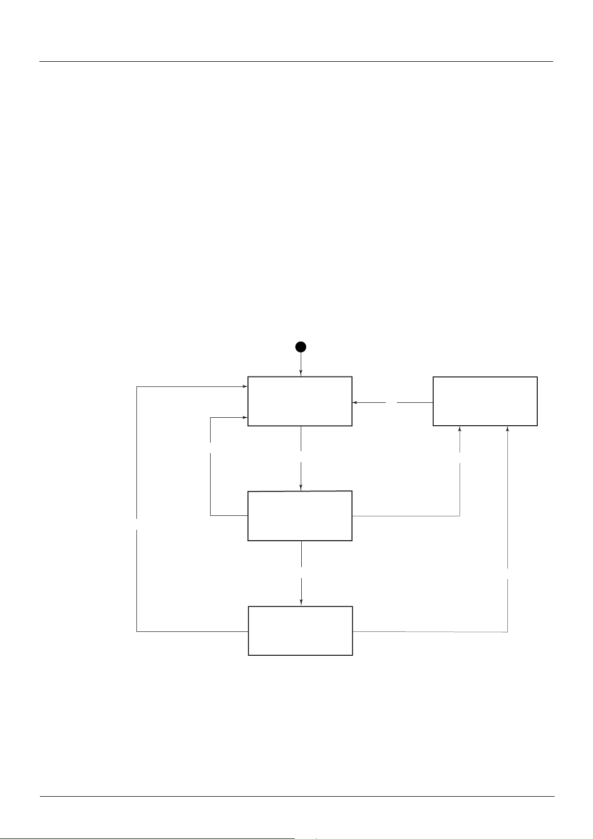
Communication monitoring
Enabling of communication channels
• A communication channel is enabled if all its parameters assigned to drive functions have been received.
- Example:
A drive is in I/O profile with speed control. Modbus constitutes both the command and reference channel.
The Modbus channel will be enabled as soon as the control word and speed reference have been received.
• The drive is only able to start if all participant channels are enabled.
- Example 1:
A drive in CiA402 profile is connected to Modbus, which is the active channel.
Unless the reference has been written at least once, it will n ot be possible to p roceed to "5 - Operati on enabled" state, even if the
"4 - Enable operation" command is sent.
- Example 2:
A drive is connected to Modbus.
The terminals are both the reference and command channel.
The operation on reference function [REF. OPERATIONS] (OAI-) is active and summing input 2 is assi gned to Modbus.
The drive will not start until the reference has been supplied by Modbus.
- Example 3:
A drive is configured for switching between the terminals and CANopen.
If the command switch is assigned to the Ethernet card, start-up is only possible once the Ethernet channel is enabled.
• A communication problem disables a communication channel.
• When switching from an enabled channel to a disabled channel, th e drive immediately triggers a network fault.
Communication
problem and
non-participant
channel
Communication
problem and
non-participant
channel
4
3
Command or
reference
parameter
received
All parameters
assigned to drive
functions have been
Channel
disconnected
1
Connected
channel
2
Channel
enabled
=1
7
Communication
problem and
participant
channel
Network fault
5
Communication
problem and
participant
channel
6
Special case involving Modbus TCP/IP Ethernet card
• The Ethernet card can generate 2 types of network fault: Network management fault and communication fault.
• If a network management fault (IP address dupli cation or FDR faul t) occurs, a drive fault i s generated reg ardless of the s tate (active,
participant, etc.) of this channel.
54
Page 55

Assignment of references from a network
Reference parameters
The Altivar 61 supports a number of reference parameters, which must be selected according to the functions used in the drive.
Function used Input to be assigned Value Reference to be sent via the network
Speed reference
(rpm)
Frequency reference
(0.1 Hz or high
resolution)
Sum [Summing ref. 2] (SA2)
Subtraction [Subtract. ref. 2] (dA2)
Multiplication [Mul tip li er ref. 2] (MA 2)
PID regulator [Ref.1 channel] (Fr1)
[Ref.1 channel] (Fr1)
[Ref.2 channel] (Fr2)
[Ref.1B channel] (Fr1b)
[Ref.1 channel] (Fr1)
[Ref.2 channel] (Fr2)
[Ref.1B channel] (Fr1b)
[Summing ref. 3] (SA3)
[Subtract. ref. 3] (dA3)
[Multiplier ref. 3] (MA3)
[Ref.1B channel] (Fr1b)
[PID feedback ass.] (PIF) [Network AI] (AIU1) PID regulator feedback (AIU1)
[AI net. channel] (AIC1) [Modbus] (Mdb) or
[Modbus] (Mdb) or
[CANopen] (CAn) or
[Com. card] (nEt)
[Modbus] (Mdb) or
[CANopen] (CAn) or
[Com. card] (nEt)
[Modbus] (Mdb) or
[CANopen] (CAn) or
[Com. card] (nEt) or
[Network AI] (AIU1)
[Modbus] (Mdb) or
[CANopen] (CAn) or
[Com. card] (nEt) or
[Network AI] (AIU1)
[Modbus] (Mdb) or
[CANopen] (CAn) or
[Com. card] (nEt) or
[Network AI] (AIU1)
[Modbus] (Mdb) or
[CANopen] (CAn) or
[Com. card] (nEt)
[CANopen] (CAn) or
[Com. card] (nEt)
Speed reference (LFRD)
Frequency reference (LFR)
Speed reference (LFRD) or Frequency reference (LFR)
Speed reference (LFRD) or Frequency reference (LFR)
[Multiplying coeff.] (MFr)
PID regulator reference (PISP)
Example 1:
The drive is to be controlled by sending the speed reference to the PID regulator via CANopen. No application fu nction is used.
The following must be assigned: [Ref.1 channel] (Fr1) = [CANopen] (CAn)
The following must be sent: Speed reference (LFRD)
Example 2:
The drive is to be controlled by sending the PID regulator reference via Modbus.
The following must be assigned: [Ref.1 channel] (Fr1) = [Modbus] (Mdb)
The following must be sent: PID regulator reference (PISP)
Example 3:
The drive is to be controlled by sending the PID regulator reference and the feedback via the Ethernet card.
The following must be assigned:
- [Ref.1 channel] (Fr1) = [Com. card] (nEt)
- [PID feedback ass.] (PIF) = [Network AI] (AIU1)
- [AI net. channel] (AIC1) = [Com. card] (nEt)
The following must be sent:
- PID regulator reference (PISP)
- PID regulator feedback (AIU1)
55
Page 56
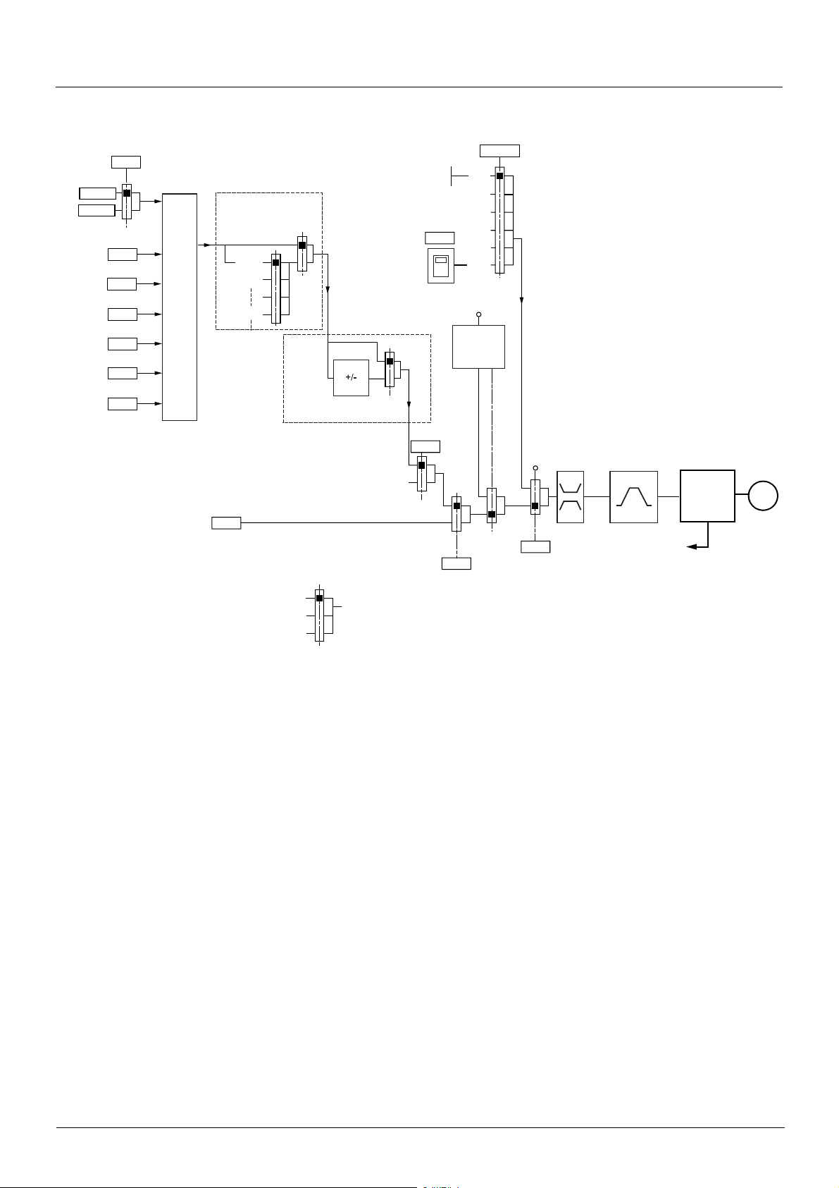
Assignment of references from a network
Without PID regulator
[Ref 1B switching]
H/>
[Ref.1 channel]
2H$
2H$>
[Ref.1B channel]
[Summing ref. 2]
FRA
;-%
[Summing ref. 3]
;-&
[Subtract. ref. 2]
@-%
[Subtract. ref. 3]
@-&
[Multiplier ref. 2]
8-%
[Multiplier ref. 3]
8-&
Network references
Fr1, Fr1b, Fr2:
• LFr or LFrd
SA2, SA3, dA2, dA3:
• LFr, LFrd, or AIU1
MA2, MA3:
•MFr or AIU1
(FRA + SA2 + SA3 - dA2 - dA3) x MA2 x MA3
[Ref.2 channel]
Preset speeds
(SP1)
SP2
SP16
2H%
nO
[PID REGULATOR]
Key:
Graphic
display
+/- speed around a
reference
PID not assigned
Parameter:
The black square represents the
factory setting assignment
nO
0V
72H
nO
:52
Channel 2
H2/
[Ref. 2 switching]
nO
AI1
AI2
AI3
AI4
LCC
LI
Jog
operation
Channel 1
nO
279/
Note: Forced local is not active in [I/O
profile].
[High
LI
speed]
HSP
LSP
FrH
FrHd
nO
[Low speed]
279
Forced local
Ramps
ACC DEC
AC2 DE2
FrO
FrOd
Power stage
M
rFr
rFrd
56
Page 57

Assignment of references from a network
With PID regulator
[Ref 1B switching]
H/>
[Ref.1 channel]
2H$
2H$>
[Ref.1B channel]
[Summing ref. 2]
;-%
[Summing ref. 3]
;-&
[Subtract. ref. 2]
@-%
[Subtract. ref. 3]
@-&
PIP1
PIP2
FRA + SA2 + SA3 - dA2 - dA3
0V
72H
Graphic
display
nO
AI1
AI2
AI3
AI4
LCC
279/
Note: Forced local is not active in [I/O
profile].
Network references
Fr1, Fr1b:
•PISP
SA2, SA3, dA2, dA3:
• LFr, LFrd or AIU1
Fr2, FPI:
• LFr or LFrd
Network feedback
•AIU1
A
PII
nO
Internal
reference
[Encoder] (PG)
rPI
nO
AI1
.....
AI4
[RP] (PI)
[Network AI]
YES
PIF
Preset PID references
PID
feedbac
k
[Ref.2 channel]
2H%
LI
Pr2
Pr4
rP2
rP3
rP4
Manual
reference
PIN
PID
A
See the table
below
Ramp
nO
PrP
Scaling
PIF1 / PIF2
PIP1 / PIP2
Preset manual references
SP2
rPF
nO
B
+
rPC
-
Channel 1
Channel 2
Error
inversion
PIC
rPE
[Ref. 2 switching]
nO
x(-1)
YES
Predictive
speed
reference
FPI
H2/
nO
279
Forced local
Restart (wake-
up) feedback or
error threshold
tLS
rSL
UPP
0
x PSr
LI
[Low speed]
Gains
Key:
[High
speed]
HSP
LSP
rdG
rPG
rIG
Ramps (1)
ACC DEC
FrH
FrHd
AC2 DE2
POH
POL
Ramps
ACC DEC
AC2
(1)
FrO
FrOd
rPO
+
Power stage
rFrd
+
M
rFr
B
Auto/
Manual
PAU
(manu)
SP16
(1)The ramp AC2 is active only at startup of the PID function and during PID "wake-ups".
Parameter:
The black square
represents the factory
setting assignment
57
Page 58

Configuration saving and switching
Saving the configuration
When a parameter is modified via the drive’s integrated display terminal or graphic display terminal, this parameter is automatically saved
to the EEPROM non-volatile memory.
Display
terminal
Current
configuration
(RAM)
Configuration 0
(EEPROM)
When a parameter is modified using a PLC or an HMI terminal via a network (Modbus, CANopen or a network card), this parameter is written
to the current configuration in the RAM volatile memory. It is not saved to the EEPROM non-volatile memory. If the drive control voltage is
disconnected, when it is reconnected, the parameter reverts to the initial value and the setting is lost.
Display
terminal
Current
configuration
(RAM)
Configuration 1
(EEPROM)
No
Configuration 2
(EEPROM)
Modbus
CANopen
Network
Factory settings
Industrial
HMI
terminal
PLC
Configuration 0
(EEPROM)
58
Configuration 1
(EEPROM)
Configuration 2
(EEPROM)
Factory settings
Page 59

Configuration saving and switching
To save the parameter, a save command must be executed using bit 1 of the extended control word (CMI).
Display
terminal
Current
configuration
(RAM)
Extended control word:
Save (CMI,1)
Configuration 0
(EEPROM)
The save command is only active if the drive is stopped, and not in "5-Operati on enabled" state.
Configuration 1
(EEPROM)
Modbus
CANopen
Set to 1
Network
Configuration 2
(EEPROM)
Industrial
HMI
terminal
PLC
Factory settings
59
Page 60

Configuration saving and switching
Restore configuration
The restore configuration command is executed using bit 2 of the extended cont rol word (CMI).
Display
terminal
Current
configuration
(RAM)
Extended control word:
Restore configuration (CMI,2)
Configuration 0
(EEPROM)
The return to factory settings command is executed usi ng bit 0 o f the extend ed control word (CMI). The type of setting is determined by the
active macro configuration parameter [Macro configuration] (CFG) and by the [PARAMETER GROUP LIST] (FrY) parameter which
defines the parameter groups concerned.
Configuration 1
(EEPROM)
Modbus
CANopen
Set to 1
Network
Configuration 2
(EEPROM)
Industrial
HMI
terminal
PLC
Factory settings
Display
terminal
Current
configuration
(RAM)
Extended control word:
Factory setting (CMI,0)
Configuration 0
(EEPROM)
The restore command is only active if the drive is stopped, and not in "5-Operation enabled" state.
Configuration 1
(EEPROM)
Modbus
CANopen
Network
Set to 1
Configuration 2
(EEPROM)
[Macro configuration]
(CFG)
Industrial
HMI
terminal
PLC
Factory settings
60
Page 61

Configuration saving and switching
Configuration switching via control word
The configuration or motor switching function (see the Programming Manual) can be used via the network or via the terminals.
Display
terminal
Current
configuration
(RAM)
Configuration switching
Terminal
s
[2 Configurations](CnF1)
[3 Configurations](CnF2)
Active
configuration
(CNFS)
Configuration 0
To use this function via a network, simply assign one or two bits of the control word to the motor or configuration switching command via
the [2 Configurations] (CnF1) and [3 Configurations] (CnF2) parameters.
The active configuration can be read in the [Config. active] (CNFS) parameter.
00 01
(EEPROM)
Configuration 1
(EEPROM)
Configuration 2
Display
terminal
Current
configuration
(RAM)
Control word:
Configuration switching
[2 Configurations](CnF1)
[3 Configurations](CnF2)
Modbus
CANopen
Network
Set to 0/1
10
11
Factory settings
(EEPROM)
Industrial
HMI
terminal
PLC
Active
configuration
(CNFS)
Configuration 0
(EEPROM)
00 01
Configuration 1
(EEPROM)
10
11
Configuration 2
(EEPROM)
Factory settings
61
Page 62

Configuration saving and switching
When the configuration or motor switching function is configured on inputs or on control word bits, to save a configuration that is already
active, set bit 1 of the extended control word (CMI) to 1.
Display
terminal
Current
configuration
(RAM)
Extended control word:
Save configuration (CMI,1)
Active
configuration
(CNFS)
When the configuration or motor switching funct i on i s co nfigu re d on in puts o r on c ontro l wo rd bits, b it 2 of th e ext en ded contr ol wo rd (CMI)
must be set to 1.
1 2 3
Configuration 0
(EEPROM)
Configuration 1
(EEPROM)
Modbus
CANopen
Set to 1
Network
Configuration 2
(EEPROM)
Industrial
HMI
terminal
PLC
Factory settings
Display
terminal
Current
configuration
(RAM)
Extended control word:
Restore configuration (CMI,2)
Active
configuration
(CNFS)
The configuration switching commands are only active if the drive is st opped, and not in "5-Operation enabled" state.
1 2 3
Configuration 0
(EEPROM)
Configuration 1
(EEPROM)
Modbus
CANopen
Network
Set to 1
Configuration 2
(EEPROM)
Industrial
HMI
terminal
PLC
Factory settings
62
Page 63

Configuration saving and switching
Function parameters
Code Description
CNF1 Parameter name: Assignment for 2 configurations
Terminal display: [2 Configurations]
Logic address: 8021 = 16#1F55 Type: WORD (listing)
CANopen index: 2032/16 Read/write: R/WS
INTERBUS index: 5FBC/9C Factory setting : 0
DeviceNet path: 9C/01/9C
See next page.
CNF2 Parameter name: Assignment for 3 configurations
Terminal display: [3 Configurations]
Logic address: 8022 = 16#1F56 Type: WORD (listing)
CANopen index: 2032/17 Read/write: R/WS
INTERBUS index: 5FBC/9D Factory setting : 0
DeviceNet path: 9C/01/9D
See next page.
CNFS Parameter name: Active configuration
Terminal display: [Config. active]
Logic address: 8020 = 16#1F54 Type: WORD (listing)
CANopen index: 2032/15 Read/write: R
INTERBUS index: 5FB9/D1
DeviceNet path: 89/01/15
0 = The parameter set switching function is not configured
1 = (CNF0): Configuration no. 0 active
2 = (CNF1): Configuration no. 1 active
3 = (CNF2): Configuration no. 2 active
Value of the control bit assigned by [2 Configurat ions] (CnF1) 0 1 0 1
Value of the control bit assigned by [3 Configurat ions] (CnF2) 0 0 1 1
Value of [Config. active] (CnFS) 1 2 3 3
Active configuration 0 1 2 2
63
Page 64

Configuration saving and switching
Assignment of logic inputs and control bits for CNF1 and CNF2
Value Assignment Description/Condition
0 Not assigned
129
to
134
135
to
138
139
to
142
187
to
191
203
to
207
219
to
223
235
to
239
[LI1] (LI1)
to
[LI6] (LI6)
[LI7] (LI7)
to
[LI10] (LI10)
[LI11] (LI11)
to
[LI14] (LI14)
[C111] (C111)
to
[C115] (C115)
[C211] (C211)
to
[C215] (C215)
[C311] (C311)
to
[C315] (C315)
[C411] (C411)
to
[C415] (C415)
Logic inputs
Drive with or without option
Logic inputs
With VW3A3201 logic I/O card
Logic inputs
With VW3A3202 extended I/O card
Control bit
With integrated Modbus regardless of configuration
Control bit
With integrated CANopen regardless of configuration
Control bit
With a communication card regardless of configuration
Control bit
With Controller Inside card regardless of configuration
Note: In [I/O profi le] (IO) configuration, LI1 cannot be accessed and if [2/3 wire control] (tCC) = [3 wire] (3C); LI2 cannot be accessed
either.
64
Page 65

Configuration saving and switching
Configuration switching by selection
The current configuration can be saved in one of the 3 non-volatile configurations in EEPROM using the "Save configuration" (SCS)
parameter. In this case, it is not necessary to assign a function in the control word.
Display
terminal
Current
configuration
(RAM)
Save configuration (SCS)
Modbus
CANopen
Network
Write
Industrial
HMI
terminal
PLC
1 2 3
Configuration 0
(EEPROM)
One of the 3 non-volatile configurations in EEPROM can be restored to the current configuration using the "Restore configuration" (FCS)
parameter.
Note: Value 64 controls the return to factory settings.
Configuration 1
(EEPROM)
Configuration 2
(EEPROM)
Factory settings
Display
terminal
Current
configuration
(RAM)
Restore configuration
(FCS)
1 2 3 64
Configuration 0
(EEPROM)
Configuration 1
(EEPROM)
Modbus
CANopen
Network
Write
Configuration 2
(EEPROM)
Industrial
HMI
terminal
PLC
Factory settings
[Macro configuration]
(CFG)
The configuration switching commands are only active if the drive is st opped, and not in "5-Operation enabled" state.
65
Page 66

Configuration saving and switching
Function parameters
Code Description
SCS Parameter name: Save configuration
Logic address: 8001 = 16#1F41 Type: WORD (listing)
CANopen index: 2032/2 Read/write: R/WS
INTERBUS index: 5FBC/9A
DeviceNet path: 9C/01/9A
0 =No save
1 = Save to configuration no. 0
2 = Save to configuration no. 1
3 = Save to configuration no. 2
FCS Parameter name: Restore configuration
Logic address: 8002 = 16#1F42 Type: WORD (listing)
CANopen index: 2032/3 Read/write: R/WS
INTERBUS index: 5FBC/9B
DeviceNet path: 9C/01/9B
0 = No restore
1 = Restore configuration no. 0
2 = Restore configuration no. 1
3 = Restore configuration no. 2
64 = Factory setting
FrY Parameter name: Parameter groups
Terminal display: [PARAMETER GROUP LIST]
Logic address: 3022 = 16#OBCE Type: WORD (bit register)
CANopen index: 2000/17 Read/write: R/WS
INTERBUS index: 5FBC/06 Factory setting: 0
DeviceNet path: 70/01/17
Selection of menus to be loaded
bit 0: = 1: [All] (ALL): All parameters
bit 1: = 1: [Drive menu] (drM): The [1 DRIVE MENU] menu without [1.9 COMMUNICATION] and [1.14 CONTROL
INSIDE MENU]. In the [7 DISPLAY CONFIG.] menu, [Return std name] returns to [No]
bit 2: = 1: [Settings] (SEt): The [1.3 SETTINGS] menu without the [IR compensation] (UFr), [Slip compensation] (SLP)
and [Mot. therm. current] (ItH) parameters
bit 3: = 1: [Motor param] (MOt): Motor parameters:
[Rated motor power] (nPr) - [Rated motor volt.] (UnS) - [Rated mot. current] (nCr) - [Rated motor freq.] (FrS) -
[Rated motor speed] (nSP)
[F5] (F5) - [V. constant power] (UCP) - [Freq. Const Power] (FCP) - [Nominal I sync.] (nCrS) - [Nom motor
spdsync] (nSPS) - [Pole pairs] (PPnS) - [Syn. EMF constant] (PHS) - [Autotune L d-axis] (LdS) - [Autotune L qaxis] (LqS) - [Cust. stator R syn] (rSAS) - [IR compensation] (UFr) - [Slip compensation] (SLP) - the motor
parameters that can be accessed in [Expert] mode
The following options can only be accessed if [Config. Source] (FCSI) = [Macro-Conf] (InI):
bit 4: = 1: [Comm. menu] (COM): The [1.9 COMMUNICATION] menu without either [Scan. IN1 address] (nMA1) to
[Scan. IN8 address] (nMA8) or [Scan.Out1 address] (nCA1) to [Scan.Out8 address] (nCA8)
bit 5: = 1: [Control Inside menu] (PLC): The [1.14 CONTROL INSIDE MENU] menu
bit 6: = 1: [Monitor config.] (MOn): The [6 MONITORING CONFIG.] menu
bit 7: = 1: [Display config.] (dIS): The [7 DISPLAY CONFIG.] menu
bits 8 to 15: Reserved (= 0 or 1)
- [Auto tuning] (tUn) - [Auto tuning state] (tUS) - [U0] (U0) to [U5] (U5) - [F1] (F1) to
66
Page 67

Parameter set switching
The parameter set switching function (see the Programming Manual) can be used via the network or via the terminals.
To use this function via a network, simply assign one or two bits of the control word to para meter set switching via the [2 Parameter sets]
(CHA1) and [3 Parameter sets] (CHA2) parameters.
The active set can be read in the "Active parameter set" (CFPS) parameter.
The parameter sets can be written via a network.
The parameter sets can be switched with the motor running.
Function parameters
Code Description
CHA1 Parameter name: Assignment for 2 sets
Terminal display: [2 Parameter sets]
Logic address: 12902 = 16#3266 Type: WORD (listing)
CANopen index: 2063/3 Read/write: R/WS
INTERBUS index: 5FBD/3A Factory setting: 0
DeviceNet path: A1/01/67
See next page.
CHA2 Parameter name: Assignment for 3 sets
Terminal display: [3 Parameter sets]
Logic address: 12903 = 16#3267 Type: WORD (listing)
CANopen index: 2063/4 Read/write: R/WS
INTERBUS index: 5FBD/3B Factory setting: 0
DeviceNet path: A1/01/68
See next page.
CFPS Parameter name: Active parameter set
Logic address: 12900 = 16#3264 Type: WORD (listing)
CANopen index: 2063/1 Read/write: R
INTERBUS index: 5FB9/EB
DeviceNet path: A1/01/65
0 = The parameter set switching function is not configured
1 = [Set 1 active] (CFP1): Parameter set no. 1 active
2 = [Set 2 active] (CFP2): Parameter set no. 2 active
3 = [Set 3 active] (CFP3): Parameter set no. 3 active
Value of the control bit assigned by [2 Parameter sets] (CHA1) 0 1 0 1
Value of the control bit assigned by [3 Parameter sets] (CHA2) 0 0 1 1
Value of "Active parameter set" (CFPS) 1 2 3 3
Active parameter set 1 2 3 3
67
Page 68

Parameter set switching
CHA1 and CHA2 assignment values
Value Assignment Description/Condition
0 [No] (nO) Not assigned
4 [Freq. Th. attain.] (FtA) Switching via [Freq. threshold] (Ftd)
13 [FreqTh.att.2] (F2A) Switching via [Freq. threshold 2] (F2d)
129
to
134
135
to
138
139
to
142
160
to
170
171
to
175
177
to
186
187
to
191
193
to
202
203
to
207
209
to
218
219
to
223
225
to
234
235
to
239
[LI1] (LI1)
to
[LI6] (LI6)
[LI7] (LI7)
to
[LI10] (LI10)
[LI11] (LI11)
to
[LI14] (LI14)
[CD00] (Cd00)
to
[CD10] (Cd10)
[CD11] (Cd11)
to
[CD15] (Cd15)
[C101] (C101)
to
[C110] (C110)
[C111] (C111)
to
[C115] (C115)
[C201] (C201)
to
[C210] (C210)
[C211] (C211)
to
[C215] (C215)
[C301] (C301)
to
[C310] (C310)
[C311] (C311)
to
[C315] (C315)
[C401] (C401)
to
[C410] (C410)
[C411] (C411)
to
[C415] (C415)
Logic inputs
Drive with or without option
Logic inputs
With VW3A3201 logic I/O card
Logic inputs
With VW3A3202 extended I/O card
Switchable bit
In [I/O profile] (IO) configuration
Switchable bit
Regardless of configuration
Control bit
With integrated Modbus in [I/O profile] (IO) configuration
Control bit
With integrated Modbus regardless of configuration
Control bit
With integrated CANopen in [I/O profile] (IO) configuration
Control bit
With integrated CANopen regardless of configuration
Control bit
With a communication card in [I/O profile] (IO) configuration
Control bit
With a communication card regardless of configuration
Control bit
With Controller Inside card in [I/O profile] (IO) configuration
Control bit
With Controller Inside card regardless of configuration
Note: In [I/O profile] (IO) configurat ion, LI1 cannot be accessed and if [2/3 wire control] (tCC) = [3 wire] (3C), LI2, C101, C2 01, C301
and C401 cannot be accessed either.
68
Page 69

Parameter set switching
Parameter sets can be loaded via the following parameters:
Address table:
No. Code Logic address: CANopen index: INTERBUS index: DeviceNet path:
1 AD01 12911 = 16#326F 2063/C 5FBF/6A 9F/01/8C
2 AD02 12912 = 16#3270 2063/D 5FBF/6B 9F/01/8D
3 AD03 12913 = 16#3271 2063/E 5FBF/6C 9F/01/8E
4 AD04 12914 = 16#3272 2063/F 5FBF/6D 9F/01/8F
5 AD05 12915 = 16#3273 2063/10 5FBF/6E 9F/01/90
6 AD06 12916 = 16#3274 2063/11 5FBF/6F 9F/01/91
7 AD07 12917 = 16#3275 2063/12 5FBF/70 9F/01/92
8 AD08 12918 = 16#3276 2063/13 5FBF/71 9F/01/93
9 AD09 12919 = 16#3277 2063/14 5FBF/72 9F/01/94
10 AD10 12920 = 16#3278 2063/15 5FBF/73 9F/01/95
11 AD11 12921 = 16#3279 2063/16 5FBF/74 9F/01/96
12 AD12 12922 = 16#327A 2063/17 5FBF/75 9F/01/97
13 AD13 12923 = 16#327B 2063/18 5FBF/76 9F/01/98
14 AD14 12924 = 16#327C 2063/19 5FBF/77 9F/01/99
15 AD15 12925 = 16#327D 2063/1A 5FBF/78 9F/01/9A
Table of values for set no. 1:
No. Code Logic address: CANopen index: INTERBUS index: DeviceNet path:
1 S101 12931 = 16#3283 2063/20 5FBF/79 9F/01/9B
2 S102 12932 = 16#3284 2063/21 5FBF/7A 9F/01/9C
3 S103 12933 = 16#3285 2063/22 5FBF/7B 9F/01/9D
4 S104 12934 = 16#3286 2063/23 5FBF/7C 9F/01/9E
5 S105 12935 = 16#3287 2063/24 5FBF/7D 9F/01/9F
6 S106 12936 = 16#3288 2063/25 5FBF/7E 9F/01/A0
7 S107 12937 = 16#3289 2063/26 5FBF/7F 9F/01/A1
8 S108 12938 = 16#328A 2063/27 5FBF/80 9F/01/A2
9 S109 12939 = 16#328B 2063/28 5FBF/81 9F/01/A3
10 S110 12940 = 16#328C 2063/29 5FBF/82 9F/01/A4
11 S111 12941 = 16#328D 2063/2A 5FBF/83 9F/01/A5
12 S112 12942 = 16#328E 2063/2B 5FBF/84 9F/01/A6
13 S113 12943 = 16#328F 2063/2C 5FBF/85 9F/01/A7
14 S114 12944 = 16#3290 2063/2D 5FBF/86 9F/01/A8
15 S115 12945 = 16#3291 2063/2E 5FBF/87 9F/01/A9
69
Page 70

Parameter set switching
Table of values for parameter set no. 2:
No. Code Logic address: CANopen index: INTERBUS index: DeviceNet path:
1 S201 12951 = 16#3297 2063/34 5FBF/88 9F/01/AA
2 S202 12952 = 16#3298 2063/35 5FBF/89 9F/01/AB
3 S203 12953 = 16#3299 2063/36 5FBF/8A 9F/01/AC
4 S204 12954 = 16#329A 2063/37 5FBF/8B 9F/01/AD
5 S205 12955 = 16#329B 2063/38 5FBF/8C 9F/01/AE
6 S206 12956 = 16#329C 2063/39 5FBF/8D 9F/01/AF
7 S207 12957 = 16#329D 2063/3A 5FBF/8E 9F/01/B0
8 S208 12958 = 16#329E 2063/3B 5FBF/8F 9F/01/B1
9 S209 12959 = 16#329F 2063/3C 5FBF/90 9F/01/B2
10 S210 12960 = 16#32A0 2063/3D 5FBF/91 9F/01/B3
11 S211 12961 = 16#32A1 2063/3E 5FBF/92 9F/01/B4
12 S212 12962 = 16#32A2 2063/3F 5FBF/93 9F/01/B5
13 S213 12963 = 16#32A3 2063/40 5FBF/94 9F/01/B6
14 S214 12964 = 16#32A4 2063/41 5FBF/95 9F/01/B7
15 S215 12965 = 16#32A5 2063/42 5FBF/96 9F/01/B8
Table of values for set no. 3:
No. Code Logic address: CANopen index: INTERBUS index: DeviceNet path:
1 S301 12971 = 16#32AB 2063/48 5FBF/97 9F/01/B9
2 S302 12972 = 16#32AC 2063/49 5FBF/98 9F/01/BA
3 S303 12973 = 16#32AD 2063/4A 5FBF/99 9F/01/BB
4 S304 12974 = 16#32AE 2063/4B 5FBF/9A 9F/01/BC
5 S305 12975 = 16#32AF 2063/4C 5FBF/9B 9F/01/BD
6 S306 12976 = 16#32B0 2063/4D 5FBF/9C 9F/01/BE
7 S307 12977 = 16#32B1 2063/4E 5FBF/9D 9F/01/BF
8 S308 12978 = 16#32B2 2063/4F 5FBF/9E 9F/01/C0
9 S309 12979 = 16#32B3 2063/50 5FBF/9F 9F/01/C1
10 S310 12980 = 16#32B4 2063/51 5FBF/A0 9F/01/C2
11 S311 12981 = 16#32B5 2063/52 5FBF/A1 9F/01/C3
12 S312 12982 = 16#32B6 2063/53 5FBF/A2 9F/01/C4
13 S313 12983 = 16#32B7 2063/54 5FBF/A3 9F/01/C5
14 S314 12984 = 16#32B8 2063/55 5FBF/A4 9F/01/C6
15 S315 12985 = 16#32B9 2063/56 5FBF/A5 9F/01/C7
70
Page 71

Parameter set switching
Code Description
VAL Parameter name: Load parameter set command
Logic address: 12901 = 16#3265 Type: WORD (listing)
CANopen index: 2063/02 Read/write: R/W
INTERBUS index:
DeviceNet path: A1/01/66
0 = Function not used or a new set of parameters has been taken into account
1 = Request to write a new set of parameters
2 = A new set of parameters is being written
Procedure:
• Write the addresses and values of the sets.
• Set VAL to 1.
• Once the new sets have been taken into account, the drive resets (VAL) to 0.
71
Page 72

Loading drive parameters
Requirement
Certain applications require parameters to be downloaded:
• When the installation starts up
• When the manufacturing range is changed
• When a faulty device is replaced
Neither the integrated ports nor the network cards of the drive provide a parameter file loading procedure (ex cept for the "FDR" faulty device
replacement mechanism of the VW3 A3 310 Modbus Ethernet TCP/IP card).
Parameter loading is therefore based on write requests that have to be programmed in the controller (PLC, etc.).
If the controller is limited to writing para meters sequentially, the final configuration risks not being identical to the one desired.
The differences between the configuration to be loaded and the real configuration result from cons istency checking of the drive parame ters.
The drive checks relationships between the parameters, and if they are not correct:
• It automatically modifies a parameter which is offered for writing (pedestal, deadband) or
• Writing of the parameter is rejected
Examples illustrating this problem are given on page 73.
The controller must therefore follow a procedure that includes a phase of disabling the consistency check function.
Procedure
All the operations described below must be carried out with the motor stopped, with no run command to the drive.
Saving the reference configuration
1. Identify the parameters of the reference drive whic h are different from the factory sett ing. These parameters can be identified easily using
the PowerSuite software (parameter list display).
2. Reserve a parameter image ta ble in the controller (PLC, etc.). Th is image table is a series of addresses and val ues. The last parameter
to be loaded is identified by an address equal to -1.
3. Enter the addresses of the modified parameters into the controller's image table by copying the list given by the PowerSuite software.
4. Initialize the values in the image table. There are two possible methods:
- Enter the values manually.
- Program an automatic read function in the controller. Connect the controller to the reference drive. Save the reference
configuration in the image table.
Load the configuration
The program in the controller (PLC, etc.) must perform the following operations:
1. Command a drive factory setting:
Write the value 16#0001 to the extended control word (8504-CMI).
2. Disable the parameter consistency check function:
Write the value 16#8000 to the extended control word (8504-CMI).
3. Load the configuration:
Write the parameters one after another using the image table.
4. Enable the parameter consistency check function:
Write the value 16#0000 to the extended control word (8504-CMI).
5. Check the drive configuration:
Read and compare the parameters one after another against the image table.
72
Page 73

Loading drive parameters
Inconsistency examples
The 2 adjustment par am e t ers [Low speed] (3105-LSP) and [High speed] (3104-HSP) comply with the consistency rule:
0 y [Low speed] (3105-LSP) y [High speed] (3104-HSP) y 10000.
Example 1
Initial configuration V Configuration to be loaded:
[High speed] (3104-HSP) = 30 Hz V [High speed] (3104-HSP) = 60 Hz
[Low speed] (3105-LSP) = 20 Hz V [Low speed] (3105-LSP) = 40 Hz
• "Request n: Request writing of [Low speed] (3105-LSP) to 40 Hz
• "Consistency check: The consistency rule [Low speed] (3105-LSP) y [High speed] (3104-HSP) is not complied with:
-The [Low speed] (3105-LSP) parameter actually written into the drive is 30 Hz.
• "Request n+1: Request writing of [High speed] (3104-HSP) = 60 Hz
• "Consistency check: The consistency rules are complied with:
-The [High speed] (3104-HSP) parameter is correctly written to 60 Hz in the driv e.
The configuration loaded is different from the configuration to be loaded:
[Low speed] (3105-LSP) = 30 Hz instead of [Low speed] (3105-LSP) = 40 Hz
The drive can operate between 30 Hz and 40 Hz, which is not desired.
Example 2
Initial configuration V Configuration to be loaded:
[High speed] (3104-HSP) = 60 Hz V [High speed] (3104-HSP) = 30 Hz
[Low speed] (3105-LSP) = 40 Hz V [Low speed] (3105-LSP) = 0 Hz
• "Request n: Request writing of [High speed] (3104-HSP) to 30 Hz
• "Consistency check: The consistency rule [Low speed] (3105-LSP) y [High speed] (3104-HSP) is not complied with:
-The [High speed] (3104-HSP) parameter actually written into the drive is 40 Hz.
• "Request n+1: Request writing of [Low speed] (3105-LSP) = 0 Hz
• "Consistency check: The consistency rules are complied with :
-The [Low speed] (3104-HSP) parameter is correctly written to 0 Hz in the drive.
The configuration loaded is different from the configuration to be loaded:
[High speed] (3104-HSP) = 40 Hz instead of [High speed] (3104-HSP) = 30 Hz
The drive can operate between 30 Hz and 40 Hz, which is not desired.
73
Page 74

Command parameters
Code Description
CMd Parameter name: Control wo rd
Terminal display: [Cmd value]
CiA402 name: controlword
DRIVECOM name: Control word
Logic address: 8601 = 16#2199
or 8501 = 16#2135 (1)
CANopen index: 6040/0 Read/write: R/W
INTERBUS index: 5FB6/1B
DeviceNet path: B7/01/01
(1)Note: This parameter is available at 2 logic addresses to optimize exchanges via Modbus messaging (Modbus function
16 = 16#10 Write Multiple Registers):
- If the drive has to be controlled in terms of speed, it is preferable to use address 8601 since the speed reference
is at address 8602.
- If the drive has to be controlled in terms of frequency, it is preferable to use address 8501 since the frequency
reference is at address 8502.
Parameter conforming to the CiA402 profile
Possible values in the IO profile
On state command [2 wire] (2C)
bit 0: Forward (on state) command
= 0: No forward command
= 1: Forward command
The assignment of bit 0 cannot be mod ified. It corresp onds to
the assignment of the terminals. It can be switched. Bit 0
(Cd00) is only active if the channel of this control word is
active.
Type: WORD (bit register)
On edge command [3 wire] (3C)
bit 0: Stop (run authorization)
= 0: Stop
= 1: Run is authorized, on a forward or reverse
command
bit 1: Forward (on 0 V 1 rising edge) command
The assignment of bits 0 and 1 cannot be modified. It
corresponds to the assignment of the terminals. It can be
switched. Bits 0 (Cd00) and 1 (Cd01) are only active if the
channel of this control word is active.
Bits 1 to 15 can be assigned to commands. Bits 2 to 15 can be assigned to commands.
For example, to change the direction of operation using bit 2 of the control word of the active channel, simply configure the
[Reverse assign.] (rrS) parameter:
• To the value [C102] (C102) ... [C402] (C402) for a fixed assignment
• To the value [CD02] (Cd02) for a switched assignment
The stop commands:
• Freewheel stop [Freewheel stop ass.] (nSt)
• Fast stop [Fast stop assign.] (FSt) are active at value 0, in the same way as on the terminals.
= 0: Stop
= 1: No stop command
DC injection braking [DC injection assign.] (dCI) is active at value 1, in the same way as on the terminals.
= 0: No braking command
= 1: Braking
If a fixed assignment is made [C101] (C101) to [C115] (C115) ... [C401] (C401) to [C415] (C415), the freewheel stop, fast
stop and DC injection braking commands are always active, even if the channel is not active.If these commands are
configured as fixed assignments, the following settings must be made in order to start, even if another channel is active:
• Freewheel stop = 1
• Fast stop = 1
• DC injection braking = 0
If a switched assignment is made [CD00] (Cd00) to [Cd15] (Cd15), the freewheel stop, fast stop and DC injection braking
commands are only active if the channel is active.
74
Page 75

Command parameters
Code Description
Possible values in CiA402 profile, separate or not separate mode
bit 0: "Switch on"/Contactor command
bit 1: "Disable voltage"/Authorization to supply AC power
bit 2: "Quick stop"/Emergency stop
bit 3: "Enable operation"/Run command
bit 4: Reserved (set to 0)
bit 5: Reserved (set to 0)
bit 6: Reserved (set to 0)
bit 7: "Fault reset"/Fault acknowledgment active on 0 V 1 rising edge
bit 8: "Halt"/Halt. Stop according to the [Type of stop] (Stt) parameter without leaving the 5 - Operation enabled state.
bit 9: Reserved (set to 0)
bit 10: Reserved (set to 0)
bit 11: Direction of rotation command. Default assignment; this bit can be assigned to another command.
= 0: Forward rotation
= 1: Reverse rotation
bit 12: Can be assigned to a command
bit 13: Can be assigned to a command
bit 14: Can be assigned to a command
bit 15: Can be assigned to a command
For the description of bits 0, 1, 2, 3, 7 and 8, see the "CiA402 profile" section.
The CiA402 standard enables the drive manufacturer to use bits 11 to 15 in a specific way. On the Altivar 61, they can be
assigned to function commands. Bit 11 is assigne d by default t o control the di rection of rotation, al though it can be assigned
to another command. A new assignment deletes the assig nment to the di rection of ro tation co mmand. Bits 12 t o 15 have no
default assignment. For example, to control DC injection braking using bit 12 of the Modbus control word, simply set the [DC
injection assign.] (dCI)) parameter to value [C212] (C212).
The fast stop command configured by [Fast stop assign.] (FSt) is active at 1:
= 0: No stop command
= 1: Stop
The DC injection braking command configured by [DC injection assign.] (dCI) is active at 1:
= 0: No braking command
= 1: Braking
With a fixed assignment ([C1pp], [C2pp], [C3pp] or [C4pp]), the fast stop and DC injection braking commands are priority
stops, even if the channel is not active. If thes e commands are co nfigu red as fixe d assignment s, the f ollowing se ttin gs must
be made in order to start, even if another channel is active:
• Fast stop command = 0
• DC injection braking command = 0
With a switched assignment ([Cdpp]), the fast stop and DC injection braking commands are only operational if the channel
is active.
The freewheel stop [Freewheel stop ass.] (nSt) command cannot be assigned in CiA402 profile.
75
Page 76

Command parameters
Code Description
CMI Parameter name: Extended control word
Logic address: 8504 = 16#2138 Type: WORD (bit register)
CANopen index: 2037/5 Read/write: R/W
INTERBUS index: 5FB6/1E
DeviceNet path: 8B/01/69
bit 0: Command for a RAM factory setting according to the [PARAMETER GROUP LIST] (FrY) parameter (active at 1).
If it is also wished to make an EEPROM factory setting, bit 1 must also be set to 1 (the two commands can be
executed simultaneously).
bit 1: Save configuration to EEPROM non-volatile memory command (active at 1).
This bit automatically changes to 0 after the reque st is ta ken into accou nt. Th e command is only a ctive i f the dri ve
is stopped, and not in "5-Operation enabled" state.
Note: If CMI is a periodic network variable, the PLC program must write it to 0 after the first request is taken into
account. The life of the EEPROM memory is limited to 100,000 write operat ions.
Note: If the motor or configuration switching function is active, the configuration in the RAM is saved to the
EEPROM in the configuration designated by [Config. active] (CnFS).
bit 2: Restore configuration to EEPROM non-volatile memory command (active on 0 to 1 rising edge).
This bit automatically changes to 0 after the request is taken into account.
The command is only active if the drive is stopped, and not in "5-Operation enabled" state.
Note: If CMI is a periodic network variable, the PLC program must write it to 0 after the first request is taken into
account.
This does not adversely affect the life of the EEPROM memory, but permanently copies the configuration
in the memory to the current configuration.
Note: If the motor or configuration switching function is active, the configuration in the EEPROM designated by
[Config. active] (CnFS) is copied to the RAM.
bit 3: Reserved (= 0)
bit 4: Reserved (= 0)
bit 5: Reserved (= 0)
bit 6: Reserved (= 0)
bit 7: Reserved (= 0)
bit 8: Reserved (= 0)
bit 9: Definition of the frequency reference (LFr) and output frequency (rFr) unit:
= 0: 0.1 Hz
= 1: Standardized value 16 signed bits based on the maximum frequency. The value 32767 corresponds to [Max
frequency] (tFr). The default value of [Max frequency] (tFr) is 60 Hz, and the resolution is then approximately
0.0018 Hz.
This function has no effect on the speed reference (LFrd) or the output speed (rFrd).
bit 10: Fast stop command (active at 1)
bit 11: DC injection braking command (active at 1). This command must not be used if [Motor control type] (Ctt) =
[Sync.
mot.] (SYn).
bit 12: Direction of rotation command
= 0: Forward
= 1: Reverse
bit 13: Reserved (= 0)
bit 14: Reserved (= 0)
bit 15: Parameter consistency check
= 0: The check is activated. Each time a parameter is written, the drive checks the relationship between the written
parameter and the configuration in the drive. For example, the [High speed] (HSP) parameter must be less than
the [Max frequency] (tFr) parameter. If an attempt is made to write a val ue greater than the [Max frequency ] (tFr)
parameter to the [High speed] (HSP) parameter, the write operation is accepted, but the value i s limited to th at of
[Max frequency] (tFr).
= 1: The check is deactivated. The drive is locked in stop mode. In this drive state, the configuration can be written
parameter by parameter and the drive does not modify the values that are written.
1V0: The change from 1 to 0 triggers a calculation of the consistency of the configuration. Some parameters can be
modified automatically by the drive.
76
Page 77

Setpoint parameters
See section “Assignment of references from a network”, page 55
Code Description
LFRD Parameter name: Speed reference
CiA402 name: vl target velocity
DRIVECOM name: Speed-Setpoint
Logic address: 8602 = 16#219A Type: INT
CANopen index: 6042/0 Read/write: R/W
INTERBUS index: 6042/0 Unit: rpm
DeviceNet path: 2A/01/08 (1)
8C/01/03 (2)
Parameter conforming to CiA402 and ODVA profiles
Signed value. This parameter changes the direction of operation according to its si gn.
LFR Parameter name: Frequency reference
Terminal display: [Frequency ref.]
Logic address: 8502 = 16#2136 Type: INT
CANopen index: 2037/3 Read/write: R/W
INTERBUS index: 5FB6/1C Unit: 0.1 Hz or standardized 16
DeviceNet path: 8B/01/67
Signed value.
The unit depends on the value of bit 9 of the extended control word (CMI):
= 0: 0.1 Hz
= 1: High resolution: Standardized value at maximum frequency on 16 signed bits. The value 32767 = 16 # 7FFF
corresponds to [Max frequency] (tFr). The default value of [Max frequency] (tFr) is 60 Hz, and the resolution is
then approximately 0.0018 Hz.
(1) ODVA standard path. It can be used for explicit messaging. Do not use it for configuri ng an assembly.
(2) Altivar path. To ensure better interchangeability, avo id using it for expl icit messaging. This is the path that must be used for configuring
an assembly.
signed bits based on the
maximum frequency (TFR)
77
Page 78

Setpoint parameters
Code Description
PISP Parameter name: PID regulator reference
Logic address: 8503 = 16#2137 Type: INT
CANopen index: 2037/4 Read/write: R/W
INTERBUS index: 5FB6/1D Unit: 1
DeviceNet path: 8B/01/68
Signed value.
If the PID regulator is to be controlled via a network, this reference must be written, in accordance with the protocol:
• Either via messaging
• Or by assigning this parameter in the periodic variables
AIU1 Parameter name: Network analog input
Terminal display: [Network AI]
Logic address: 5281 = 16 #14A1 Type: INT
CANopen index: 2016/52 Read/write: R/W
INTERBUS index: 5FB9/43 Unit: 1
DeviceNet path: 7B/01/52
MFr Parameter name: Multiplying coefficient
Terminal display: [Multiplying coeff.]
Logic address: 11831 = 16#2E37 Type: UINT
CANopen index: 2058/20 Read/write: R/W
INTERBUS index: 5FB6/38 Unit: 1%
DeviceNet path: 9C/01/20
78
Page 79

Status parameters
Code Description
ETA Parameter name: Status word
CiA402 name: Statusword
DRIVECOM name: Statusword
Logic address: 8603 = 16#219B
or 3201 = 16#0C81 (1)
CANopen index: 6041/0 Read/write: R
INTERBUS index: 6041/0
DeviceNet path: 71/01/02
(1)Note: This parameter is available at 2 logic addresses to optimize exchanges via Modbus messaging (Modbus function
4 = 16#04 Read Input Registers):
- If the drive has to be monitored in terms of speed, it is preferable to use address 8603 since the output speed is
at address 8604.
- If the drive has to be monitored in terms of frequency, it is preferable to use address 3201 since the output
frequency is at address 3202.
Parameter conforming to CiA402 profile
Possible values in the IO profile
Note: The value is identical in the CiA402 profile and the I/O profile. In the I/O profile, the description of the values is
simplified and does not refer to the CiA402 (Drivecom) state chart.
bit 0: Reserved
bit 1: Ready
= 0: Not ready, = 1: Ready
bit 2: Running
= 0: The drive will not start if a reference other than zero is applied.
= 1: Running, if a reference other than zero is applied, the drive can start.
bit 3: Fault
= 0: No fault, = 1: Fault
Type: WORD (bit register)
bit 4: Power section line supply present
= 0: Power section line supply absent, = 1: Power section line supply present
bit 5: Reserved
bit 6: Reserved
bit 7: Alarm
= 0: No alarm, = 1: Alarm
bit 8: Reserved
bit 9: Command via a network
= 0: Command via the terminals or the graphic display terminal, = 1: Command via a network
Note: The network can be integrated Modbus, CANopen, a communication card or the Controller Inside card. This is not
necessarily the network via which the status word is read. Therefore if the command comes from CANopen (CANopen
command channel active) and the status word (ETA) is read via an Ethernet card, the data item "Command via a network"
= 1. This does not mean that control can be carried out v ia the Ethernet card. For more information, see the "Active command
channel" (CCC) and "Active reference channel" (CRC) parameters.
bit 10: Reference reached
= 0: The reference is not reached, = 1: The reference has been reached
bit 11: Reference outside limits
= 0: The reference is within the limits, = 1: The reference is not within t he limits
When the drive is in speed mode, the limits are defined by the "Low speed (LSP)" and "High speed (HSP)"
parameters. When the torque function is activated, refer to the description of this function (see the Programming
Manual).
bits 12 and 13: Reserved
bit 14: Stop via STOP key
= 0: STOP key not pressed, = 1: Stop triggered by the STOP key on the graphic display terminal
bit 15: Direction of rotation
= 0: Forward rotation at output, = 1: Reverse rotation at output
79
Page 80

Status parameters
Code Description
Possible values in CiA402 profile
bit 0: "Ready to switch on", awaiting power section line supply
bit 1: "Switched on", ready
bit 2: "Operation enabled", running
bit 3: "Fault"
= 0: No fault
= 1: Fault
bit 4: "Voltage enabled", power section line supply present
= 0: Power section line supply absent
= 1: Power section line supply present
When the drive is powered by the power section only, this bit is always at 1.
bit 5: "Quick stop"/Emergency stop
bit 6: "Switched on disabled", power section line supply locked
bit 7: "Warning", alarm
= 0: No alarm
= 1: Alarm
bit 8: Reserved
bit 9: "Remote", command or reference via the network
= 0: Command or reference via the terminals
= 1: Command or reference via the network
bit 10: "Target reached", reference reached
= 0: The reference is not reached
= 1: The reference has been reached
When the drive is in speed mode, this is the speed reference. When the torque function is activated, refer to the
description of this function (see the Programming Manual). Wh en the drive stops, the reference has been reached.
bit 11: "Internal limit active", reference outside limits
= 0: The reference is within the limits
= 1: The reference is not within the limits
When the drive is in speed mode, the limits are defined by the "Low speed (LSP)" and "High speed (HSP)"
parameters. When the torque function is activated, refer to the description of this function (see the Programming
Manual).
bit 12: Reserved
bit 13: Reserved
bit 14: "Stop key", STOP via stop key
= 0: STOP key not pressed
= 1: Stop triggered by the STOP key on the graphic display terminal
bit 15:"Direction", direction of rotation
= 0: Forward rotation at output
= 1: Reverse rotation at output
The combination of bits 0, 1, 2, 4, 5 and 6 defines the state in the DSP 402 state chart (see the CiA402 profile section).
80
Page 81

Status parameters
Code Description
ETI Parameter name: Extended status word
Logic address: 3206 = 16#0C86 Type: WORD (bit register)
CANopen index: 2002/7 Read/write: R
INTERBUS index: 5FB9/08
DeviceNet path: 71/01/07
bit 0: = 1: Access to the EEPROM non-volatile memory in progress
bit 1: = 0: No parameter consistency check
= 1: Parameter consistency check
bit 2: = 0: The drive is not in fault state or a fault is present
= 1: The drive is in fault state but the fault is no longer present (not acknowledged)
bit 3: Reserved
bit 4: = 1: Drive in speed regulation mode
bit 5: = 1: DC injection braking (identical to LSR4, bit 11)
bit 6: = 0: Drive in steady state
= 1: Drive in transient state
bit 7: = 1: Motor thermal state threshold reached for the active motor
bit 8: = 1: Overbraking (identical to LSR5, bit 1)
bit 9: = 1: Acceleration in progress (identical to LSR4, bit 13)
bit 10: = 1: Deceleration in progress (identical to LSR4, bit 14)
bit 11: = 1: Current or torque limiting in progress
bit 12: = 1: Fast stop in progress (identical to LSR4, bit 15)
bit 13: bit 13 = 0 and bit 14 = 0: Command via the terminals
bit 14: bit 13 = 1 and bit 14 = 0: Command via the graphic display terminal
bit 13 = 0 and bit 14 = 1: Command via Modbus
bit 13 = 1 and bit 14 = 1: Command via CANopen, the network card or the "Controller Inside" card
bit 15: = 0: Forward operation applied before the ramp
= 1: Reverse operation applied before the ramp
LRS1 Parameter name: Extended status word 1
Logic address: 3250 = 16#0CB2 Type: WORD (bit register)
CANopen index: 2002/33 Read/write: R
INTERBUS index: 5FB9/1E
DeviceNet path: 71/01/33
bit 0: Reserved
bit 1: = 1: The drive is in fault state
bit 2: = 0: The drive is locked, the motor is not powered
= 1: The drive is unlocked, power can be supplied to the motor (RUN state)
bit 3: = 1: The output contactor is controlled
bit 4: = 1: Frequency threshold (ftd) reached: [Freq. Th. attained] (FtA)
bit 5: = 1: High speed (HSP) reached: [HSP attained] (FLA)
bit 6: = 1: Current threshold (Ctd) reached: [Current Th. attained] (CtA)
bit 7: = 1: Frequency reference reached: [Frequency ref. att.] (SrA)
bit 8: = 1: Motor 1 thermal state threshold [Motor therm. level] (ttd) reached: [Motor th. state att.] (tSA)
bit 9: Reserved
bit 10: = 1: PID regulator error alarm: [PID error al] (PEE)
bit 11: = 1: PID regulator feedback alarm: [PID fdbk al.] (PFA)
bit 12: = 1: 4-20 mA alarm on analog input AI2: [AI2 4-20 mA loss] (LFF2)
bit 13: = 1: Second frequency threshold (ftd) reached: [Freq. Th. 2 attained] (FA2)
bit 14: = 1: Drive thermal state threshold [Drv therm. state al] (tHA) reached: [Th. drv. att.] (tAd)
bit 15: Reserved
81
Page 82

Status parameters
Code Description
LRS2 Parameter name: Extended status word 2
Logic address: 3251 = 16#0CB3 Type: WORD (bit register)
CANopen index: 2002/34 Read/write: R
INTERBUS index: 5FB9/1F
DeviceNet path: 71/01/34
bit 0: = 1: [High Ref.] (rtAH): Frequency reference is greater than the threshold [High Freq. Ref. Thr.] (rtd)
bit 1: = 1: [Low Ref.] (rtAL): Frequency reference is less than the threshold [Low Freq. Ref. Thr.] (rtdL)
bit 2: = 1: [Low F.Thd.] (FtAL): Frequency is less than the threshold [Low Freq.Threshold] (FtdL)
bit 3: = 1: [2Low F.Thld] (F2AL): Frequency is less than the threshold [2 Freq. Threshold] (F2dL)
bit 4: = 1: [Low I Thres. Attain.] (CtAL): Current is less than the threshold [Low I Threshold] (CtdL)
bit 5: = 1: [Pro.Undload] (ULA): Process underload alarm
bit 6: = 1: [Ovld.P.Alrm] (OLA): Process overload alarm
bit 7: = 1: [PID high Al.] (PFAH): PID feedback alarm greater than [Max fbk alarm] (PAH)
bit 8: = 1: [PID low Al.] (PFAL): PID feedback alarm less than [Min fbk alarm] (PAL)
bit 9: = 1: [Regul.Alarm] (PISH): PID regulator fault (cannot reach reference)
bit 10: = 1: [Emerg. Run] (Ern): The drive is in emergency run mode
bits 11 to 15: Reserved
LRS3 Parameter name: Extended status word 3
Logic address: 3252 = 16#0CB4 Type: WORD (bit register)
CANopen index: 2002/35 Read/write: R
INTERBUS index: 5FB9/20
DeviceNet path: 71/01/35
bit 0: = 0: Reference channel 1 (Fr1) or 1B (Fr1b) is active
= 1: Reference channel 2 (Fr2) is active
bit 1: = 0: Command channel 1 (Cd1) is active
= 1: Command channel 2 (Cd2) is active
bit 2: = 0: Ramp set 1 (ACC) and (dEC)
= 1: Ramp set 2 (AC2) and (dE2)
bit 3: = 0: Current limit 1 (CLI) is active
= 1: Current limit 2 (CL2) is active
bit 4: Reserved
bit 5: = 1: Motor 2 thermal state threshold [Motor2 therm. level] (ttd2) reached: [Th.mot2 att] (tS2)
bit 6: = 1: Motor 3 thermal state threshold [Motor3 therm. level] (ttd3) reached: [Th.mot3 att] (tS3)
bit 7: Reserved
bit 8: = 1: 24 VDC external power supply present
bit 9: = 1: Stop on low speed time limit function [Low speed time out] (tLS)
bit 10: = 1: The command and reference are given by the graphic display terminal
bit 11: Reserved
bit 12: Reserved
bit 13: Reserved
bit 14: Reserved
bit 15: = 0: The output torque is positive (forward)
= 1: The output torque is negative (reverse)
82
Page 83

Status parameters
Code Description
LRS4 Parameter name: Extended status word 4
Logic address: 3253 = 16#0CB5 Type: WORD (bit register)
CANopen index: 2002/36 Read/write: R
INTERBUS index: 5FB9/21
DeviceNet path: 71/01/36
bit 0: = 1: Configuration 0 is active
bit 1: = 1: Configuration 1 is active [Cnfg.1 act.] (CnF1)
bit 2: = 1: Configuration 2 is active [Cnfg.2 act.] (CnF2)
bit 3: Reserved
bit 4: = 1: Parameter set 1 is active: [Set 1 active] (CFP1)
bit 5: = 1: Parameter set 2 is active: [Set 2 active] (CFP2)
bit 6: = 1: Parameter set 3 is active: [Set 3 active] (CFP3)
bit 7: Reserved
bit 8: = 0: Power section line supply present
= 1: Power section line supply absent
bit 9: = 1: Motor "fluxing" in progress: [In motor fluxing] (FLX)
bit 10: = 1: The motor is "fluxed"
bit 11: = 1: DC injection braking (identical to ETI, bit 5)
bit 12: = 1: Current limiting in progress
bit 13: = 1: Acceleration in progress (identical to ETI, bit 9)
bit 14: = 1: Deceleration in progress (identi cal to ETI, bit 10)
bit 15: = 1: Fast stop in progress: [Fast stop in prog.] (FSt) (identical to ETI, bit 12)
LRS5 Parameter name: Extended status word 5
Logic address: 3254 = 16#0CB6 Type: WORD (bit register)
CANopen index: 2002/37 Read/write: R
INTERBUS index: 5FB9/22
DeviceNet path: 71/01/37
bit 0: = 1: Drive DC bus loading: [DC bus loading] (dbL)
bit 1: = 1: Drive braking [In braking] (brS)
bit 2: = 1: The "Power Removal" function is active
bit 3: = 1: Automatic restart attempts in progress: [Auto restart] (AUtO)
bit 4: = 1: "Auto-tuning" in progress: [Auto-tuning] (tUn)
bit 5: = 1: Controlled stop in progress following loss of power section line supp ly (CTL)
bit 6: = 1: The drive cannot follow the configured deceleration ramp, dece leration automatically adapted (OBR)
bit 7: = 1: Controlled output cut in progress (SOC)
bit 8: Reserved
bit 9: = 1: The line contactor is active
bit 10: Reserved
bit 11: Reserved
bit 12: Reserved
bit 13: = 1: Current present in the motor (MCP)
bit 14: Reserved
bit 15: Reserved
83
Page 84

Status parameters
Code Description
LRS6 Parameter name: Extended status word 6
Logic address: 3255 = 16#0CB7 Type: WORD (bit register)
CANopen index: 2002/38 Read/write: R
INTERBUS index: 5FB9/23
DeviceNet path: 71/01/38
bit 0: = 1: Alarm group 1 is active
bit 1: = 1: Alarm group 2 is active
bit 2: = 1: Alarm group 3 is active
bit 3: = 1: Probe 1 alarm: [PTC1 alarm] (PtC1)
bit 4: = 1: Probe 2 alarm: [PTC2 alarm] (PtC2)
bit 5: = 1: LI6 PTC probe alarm: [LI6=PTC alarm] (PtC3)
bit 6: Reserved
bit 7: = 1: External fault [External fault alarm] (EtF)
bit 8: = 1: Undervoltage alarm [Undervoltage] (USA)
bit 9: = 1: The power section line supply loss detection threshold for a controlled stop has been reached (undervoltage
warning)
bit 10: Reserved
bit 11: = 1: Drive overheat alarm (tHA)
bit 12: Reserved
bit 13: Reserved
bit 14: Reserved
bit 15: = 1: Current or torque limit alarm after time-out [Trq/I limit. time out] (StO)
LRS7 Parameter name: Extended status word 7
Logic address: 3256 = 16#0CB8 Type: WORD (bit register)
CANopen index: 2002/39 Read/write: R
INTERBUS index: 5FB9/24
DeviceNet path: 71/01/39
bit 0: = 1: Reference channel 1 (Fr1) or 1B (Fr1b) is active
bit 1: = 1: Reference channel 2 (Fr2) is active
bit 2: = 1: Command channel 1 (Cd1) is active
bit 3: = 1: Command channel 2 (Cd2) is active
bit 4: = 1: Reference channel 1B (Fr1b) is active
bit 5: Reserved
bit 6: Reserved
bit 7: Reserved
bit 8: = 1: IGBT thermal state alarm
bit 9: = 1: Braking resistor overload alarm
bit 10: = 1: Alarm sent by the "Controller Inside" card
bit 11: = 1: 4-20 mA alarm on analog input AI3: [AI3 4-20mA loss] (LFF3)
bit 12: = 1: 4-20 mA alarm on analog input AI4: [AI4 4-20mA loss] (LFF4)
bit 13: = 1: DC bus precharging contactor controlled (DC0)
bit 14: = 1: Flow limitation function active
bit 15: Reserved (= 0)
84
Page 85

Status parameters
Code Description
LRS8 Parameter name: Extended status word 8
Logic address: 3257 = 16#0CB9 Type: WORD (bit register)
CANopen index: 2002/3A Read/write: R
INTERBUS index: 5FB9/25
DeviceNet path: 71/01/3A
bit 0: Reserved (= 0)
bit 1: Reserved (= 0)
bit 2: Reserved (= 0)
bit 3: Reserved (= 0)
bit 4: Reserved (= 0)
bit 5: Reserved (= 0)
bit 6: Reserved (= 0)
bit 7: Reserved (= 0)
bit 8: Reserved (= 0)
bit 9: Reserved (= 0)
bit 10: Reserved (= 0)
bit 11: Reserved (= 0)
bit 12: Reserved (= 0)
bit 13: Reserved (= 0)
bit 14: Reserved (= 0)
bit 15: = 1: Drive ready (rdY)
CRC Parameter name: Active reference channel
Logic address: 8441 = 16#20F9 Type: WORD (bit register)
CANopen index: 2036/2A Read/write: R
INTERBUS index: 5FB9/D2
DeviceNet path: 8B/01/2A
bit 0: = 1: The terminals are the active reference channel via an analog input
bit 1: Reserved (= 0)
bit 2: = 1: The graphic display terminal is the active reference channel
bit 3: = 1: Modbus is the active reference channel
bit 4: Reserved (= 0)
bit 5: Reserved (= 0)
bit 6: = 1: CANopen is the active reference channel
bit 7: = 1: The terminals are the active reference channel in +/- speed
bit 8: = 1: The graphic display terminal is the active reference channel in +/- speed
bit 9: = 1: The network card is the active reference channel
bit 10: = 1: The "Controller Inside" card is the active reference channel
bit 11: Reserved (= 0)
bit 12: Reserved (= 0)
bit 13: Reserved (= 0)
bit 14: Reserved (= 0)
bit 15: = 1: The PowerSuite software workshop is the active reference channel
85
Page 86

Status parameters
Code Description
CCC Parameter name: Active command channel
Logic address: 8442 = 16#20FA Type: WORD (bit register)
CANopen index: 2036/2B Read/write: R
INTERBUS index: 5FB9/D3
DeviceNet path: 8B/01/2B
bit 0: = 1: The terminals are the active command channel
bit 1: Reserved (= 0)
bit 2: = 1: The graphic display terminal is the active command channel
bit 3: = 1: Modbus is the active command channel
bit 4: Reserved (= 0)
bit 5: Reserved (= 0)
bit 6: = 1: CANopen is the active command channel
bit 7: = 1: The terminals are the active command channel in +/- speed
bit 8: = 1: The graphic display terminal is the active command channel in +/ - speed
bit 10: = 1: The "Controller Inside" card is the active command channel
bit 11: Reserved (= 0)
bit 12: Reserved (= 0)
bit 13: Reserved (= 0)
bit 14: Reserved (= 0)
bit 15: = 1: The PowerSuite software workshop is the active command channel
CFPS Parameter name: Active parameter set
Logic address: 12900 = 16#3264 Type: WORD (listing)
CANopen index: 2063/01 Read/write: R
INTERBUS index: 5FB9/EB
DeviceNet path: A1/01/65
0 : The parameter set switching function is not configured
1 = [Set 1 active] (CFP1): Parameter set no. 1 active
2 = [Set 2 active] (CFP2): Parameter set no. 2 active
3 = [Set 3 active] (CFP3): Parameter set no. 3 active
CNFS Parameter name: Active configuration
Terminal display: [Config. Active]
Logic address: 8020 = 16#1F54 Type: WORD (listing)
CANopen index: 2032/15 Read/write: R
INTERBUS index: 5FB9/D1
DeviceNet path: 89/01/15
0 : The motor or configuration switching function is not configured
1 = (CNF0): Configuration no. 0 active
2 = (CNF1): Configuration no. 1 active
3 = (CNF2): Configuration no. 2 active
86
Page 87

Output value parameters
Output values (speed)
Code Description
rFrd Parameter name: Output speed
CiA402 name: vl control effort
DRIVECOM name: Speed-Actual-Value
Logic address: 8604 = 16#219C Type: INT
CANopen index: 6044/0 Read/write: R
INTERBUS index: 6044/0 Unit: rpm
DeviceNet path: 2A/01/07 (1)
8C/01/05 (2)
Parameter conforming to CiA402 and ODVA profiles
Signed value.
If the drive is in open-loop mode, the speed value is estimated.
If the drive is in closed-loop mode, the speed value is measured on the sensor.
This parameter is linked to the "Output frequency" (rFr) parameter for which the unit is 0.1 Hz.
rFr Parameter name: Output frequency
Terminal display: [Output frequency]
Logic address: 3202 = 16#C82 Type: INT
CANopen index: 2002/3 Read/write: R
INTERBUS index: 5FB9/04 Unit: 0.1 Hz or standardized 16
DeviceNet path: 71/01/03
Signed value.
The unit depends on the value of bit 9 of the extended control word:
= 0: 0.1 Hz
= 1: Standardized value on 16 signed bits at maximum frequency. The value 32767 corresponds to [Max frequency]
(TFR). The default value of [Max frequency] (TFR) is 60 Hz, and the resolution is then approximately 0.0018 Hz.
(1) ODVA standard path. It can be used for explicit messaging. Do not use it for configuri ng an assembly.
(2) Altivar path. To ensure better interchangeability, avo id using it for expl icit messaging. This is the path that must be used for configuring
an assembly.
signed bits based on the
maximum frequency (TFR)
87
Page 88

Output value parameters
Output values (torque)
Code Description
Otr Parameter name: Output torque
Terminal display: [Motor torque]
CiA402 name: Torque actual value
DRIVECOM name: Torque-Actual-Value
Logic address: 3205 = 16#0C85 Type: INT
CANopen index: 6077/0 Read/write: R
INTERBUS index: 5FB9/07 Unit:
DeviceNet path: 71/01/06
Parameter conforming to CiA402 profile
Signed value.
The "Nominal motor torque" is not accessible as a drive parameter. It is the result of other characteristics.
0.001 "Nominal motor torque"
88
Page 89

Output value parameters
Output values (motor)
Code Description
LCr Parameter name: Motor current
Terminal display: [Motor current]
Logic address: 3204 = 16#0C84 Type: UINT
CANopen index: 2002/5 Read/write: R
INTERBUS index: 5FB9/06 Unit: 0.1 A
DeviceNet path: 2A/01/09 (1)
71/01/05 (2)
Parameter conforming to ODVA profile
UOP Parameter name: Motor voltage
Terminal display: [Motor voltage]
Logic address: 3208 = 16#0C88 Type: UINT
CANopen index: 2002/9 Read/write: R
INTERBUS index: 5FB9/0A Unit: 1 V
DeviceNet path: 71/01/09
OPr Parameter name: Motor power
Terminal display: [Motor power]
Logic address: 3211 = 16#0C8B Type: INT
CANopen index: 2002/C Read/write: R
INTERBUS index: 5FB9/0C Unit: 1%
DeviceNet path: 71/01/0C
UNT Parameter name: Units of parameters APH, PTH, RTH and RTHI
Logic address: 3234 = 16#0CA2 Type: WORD (bit register)
CANopen index: 2002/23 Read/write: R
INTERBUS index: 5FB9/18
DeviceNet path: 71/01/23
The unit changes automatically when the value reaches the maximum format of the parameter.
bit 0 + bit 1 = unit of APH: 0 = Wh, 1 = kWh, 2 = MWh
bit 2 + bit 3 = unit of PTH: 0 = seconds, 1 = minutes, 2 = hours
bit 4 + bit 5 = unit of RTH: 0 = seconds, 1 = minutes, 2 = hours
bit 6 + bit 7 = unit of RTHI: 0 = seconds, 1 = minutes, 2 = hours
bit 8 + bit 9 = unit of IPHR: 0 = Wh, 1 = kWh, 2 = MWh
bit 10 + bit 11 = unit of IPH: 0 = Wh, 1 = kWh, 2 = MWh
bits 12 to 15: Reserved (= 0)
(1) ODVA standard path. It can be used for explicit messaging. Do not use it for configuri ng an assembly.
(2) Altivar path. To ensure better interchangeability, avo id using it for expl icit messaging. This is the path that must be used for configuring
an assembly.
89
Page 90

Reference parameters
References (speed)
Code Description
FrHd Parameter name: Speed reference before ramp
Logic address: 8605 = 16#219D Type: INT
CANopen index: 2038/6 Read/write: R
INTERBUS index: 6043/0 Unit: rpm
DeviceNet path: 8C/01/06
FrOd Parameter name: Speed reference after ramp
Terminal display:
CiA402 name: vl velocity demand
DRIVECOM name: Speed-Reference-Variable
Logic address: 8641 = 16#21C1 Type: INT
CANopen index: 6043/0 Read/write: R
INTERBUS index: 5FB9/DB Unit: rpm
DeviceNet path: 8C/01/2A
Parameter conforming to CiA402 profile
Signed value.
This parameter is linked to the "Frequency after ramp" (FRO) parameter for which the unit is 0.1 Hz.
FrH Parameter name: Frequency reference before ramp
Terminal display: [Frequency ref.]
Logic address: 3203 = 16#0C83 Type: INT
CANopen index: 2002/4 Read/write: R
INTERBUS index: 5FB9/05 Unit: 0.1 Hz
DeviceNet path: 71/01/04
FrO Parameter name: Frequency reference after ramp
Logic address: 9021 = 16#233D Type: INT
CANopen index: 203C/16 Read/write: R
INTERBUS index: 5FB9/DC Unit: 0.1 Hz
DeviceNet path: 8E/01/16
90
Page 91

Reference parameters
References (regulator)
See section “Assignment of references from a network”, page 55.
Code Description
rPC Parameter name: PID reference after ramp
Terminal display: [PID reference]
Logic address: 11982 = 16#2ECE Type: UINT
CANopen index: 2059/53 Read/write: R
INTERBUS index: 5FB9/E8 Unit: 1
DeviceNet path: 9C/01/B7
rPF Parameter name: PID regulator feedback reference
Terminal display: [PID feedback]
Logic address: 11981 = 16#2ECD Type: UINT
CANopen index: 2059/52 Read/write: R
INTERBUS index: 5FB9/E7 Unit: 1
DeviceNet path: 9C/01/B6
rPE Parameter name: PID regulator discrepancy
Terminal display: [PID error]
Logic address: 11980 = 16#2ECC Type: INT
CANopen index: 2059/51 Read/write: R
INTERBUS index: 5FB9/E6 Unit: 1
DeviceNet path: 9C/01/B5
rPO Parameter name: PID regulator limit output reference
Terminal display: [PID Output]
Logic address: 11983 = 16#2ECF Type: INT
CANopen index: 2059/54 Read/write: R
INTERBUS index: 5FB9/E9 Unit: 0.1 Hz
DeviceNet path: 9C/01/B8
91
Page 92

Measurement parameters
Input measurements
Code Description
ULn Parameter name: Power supply voltage
Terminal display: [Mains voltage]
Logic address: 3207 = 16#0C87 Type: UINT
CANopen index: 2002/8 Read/write: R
INTERBUS index: 5FB9/09 Unit: 0.1 V
DeviceNet path: 71/01/08
IPr Parameter name: Power consumed by the drive
Terminal display: [Input Power]
Logic address: 3218 = 16#0C92 Type: UINT
CANopen index: 2002/13 Read/write: R
INTERBUS index: 5FB9/11 Unit: 0.01 kW (drives y 75 kW)
1 kW (drives > 75 kW)
DeviceNet path: 113/01/19
IPHr Parameter name: Energy consumed by the drive
Terminal display: [Consumption]
Logic address: 3237 = 16#0CA5 Type: UINT
CANopen index: 2002/26 Read/write: R
INTERBUS index: 5FB9/1B Unit: According to UNT parame t er,
DeviceNet path: 71/01/26
page
89
92
Page 93

Measurement parameters
Thermal states
Code Description
tHd Parameter name: Drive thermal state
Terminal display: [Drv. thermal state]
Logic address: 3209 = 16#0C89 Type: UINT
CANopen index: 2002/A Read/write: R
INTERBUS index: 5FB9/0B Unit: 1%
DeviceNet path: 71/01/0A
tHr Parameter name: Motor thermal state
Terminal display: [Motor thermal state]
Logic address: 9630 = 16#259E Type: UINT
CANopen index: 2042/1F Read/write: R
INTERBUS index: 5FB9/DF Unit: 1%
DeviceNet path: 91/01/1F
tHb Parameter name: DBR thermal state
Terminal display: [DBR thermal state]
Logic address: 14114 = 16#3722 Type: UINT
CANopen index: 206F/F Read/write: R
INTERBUS index: 5FBD/63 Unit: 1%
DeviceNet path: A7/01/73
93
Page 94

Measurement parameters
Time
Code Description
rtH Parameter name: Total motor operating time
Terminal display: [Run time]
Logic address: 3231 = 16#0C9F Type: UINT
CANopen index: 2002/20 Read/write: R
INTERBUS index: 5FB9/15 Unit: According to UNT parameter,
DeviceNet path: 71/01/20
rtHI Parameter name: Internal motor operating time
Logic address: 3232 = 16#0CA0 Type: UINT
CANopen index: 2002/21 Read/write: R
INTERBUS index: 5FB9/16 Unit: According to UNT parameter,
DeviceNet path: 71/01/21
page
page
89
89
PtH Parameter name: Total drive operating time
Terminal display: [Power on time]
Logic address: 3233 = 16#0CA1 Type: UINT
CANopen index: 2002/22 Read/write: R
INTERBUS index: 5FB9/17 Unit: According to UNT parameter,
DeviceNet path: 71/01/22
tAC Parameter name: IGBT alarm time
Terminal display: [IGBT alarm counter]
Logic address: 3235 = 16#0CA3 Type: UINT
CANopen index: 2002/24 Read/write: R
INTERBUS index: 5FB9/19 Unit: 1 s
DeviceNet path: 71/01/24
dAY Parameter name: Date
Logic address: 7391 = 16#1CDF Type: UINT
CANopen index: 202B/5C Read/write: R
INTERBUS index: 5FB9/CE Unit: See page 95
DeviceNet path: 85/01/C0
page
89
tIME Parameter name: Time
Logic address: 7392 = 16#1CE0 Type: UINT
CANopen index: 202B/5D Read/write: R
INTERBUS index: 5FB9/CF Unit: See page 95
DeviceNet path: 85/01/C1
94
Page 95

Measurement parameters
Code Description
PEt Parameter name: Total process operating time
Terminal display: [Proc. Operat. Time]
Logic address: 3236 = 16#0CA4 Type: UINT
CANopen index: 2002/25 Read/write: R/W
INTERBUS index: 5FB9/1A Unit: According to UNT parame t er,
DeviceNet path: 71/01/25
Same parameter as [Run time] (rtH), but can be accessed in write mode by users.
Format of "Date" and "Time" parameters
Date and time are binary-coded using the corresponding word bits indicated in the table below.
Note: The value 0 for year corresponds to the year 2000 (2006 = 36, for example).
Bits 15 14 13 12 11 10 9 8 7 6 5 4 3 2 1 0
Year X X X X X X X
Date
Time
Month X X X X
Day X X X X X
Hours X X X X X X X X
Minutes X X X X X X X X
page
89
95
Page 96

I/O parameters
Logic I/O
Code Description
IL1r Parameter name: Logic input map
Logic address: 5202 = 16#1452 Type: WORD (bit register)
CANopen index: 2016/3 Read/write: R
INTERBUS index: 5FB9/2B Unit: DeviceNet path: 7B/01/03
bit 0: Value of LI1
bit 1: Value of LI2
bit 2: Value of LI3
bit 3: Value of LI4
bit 4: Value of LI5
bit 5: Value of LI6
bit 6: Value of LI7 If a logic I/O extension card is installed
bit 7: Value of LI8
bit 8: Value of LI9
bit 9: Value of LI10
bit 10: Value of LI11 If an extended I/O extension card is installed.
bit 11: Value of LI12
bit 12: Value of LI13
bit 13: Value of LI14
bit 14: Reserved (= 0)
bit 15: Reserved (= 0)
OL1r Parameter name: Logic output map
Logic address: 5212 = 16#145C Type: WORD (bit register)
CANopen index: 2016/D Read/write: R/W
INTERBUS index: 5FB6/4E (reading via PCP)
5FB9/2D (writing via PCP)
DeviceNet path: 7B/01/0D
bit 0: Value of R1
bit 1: Value of R2
bit 2: Value of R3, if a logic I/O extension card is installed
bit 3: Value of R4, if an extended I/O extensio n card is installed
bit 4: Reserved (= 0)
bit 5: Reserved (= 0)
bit 6: Reserved (= 0)
bit 7: Reserved (= 0)
Unit: -
bit 8: Value of LO1 If a logic I/O extension card is installed
bit 9: Value of LO2
bit 10: Value of LO3 If an extended I/O extension card is installed
bit 11: Value of LO4
bit 12: Reserved (= 0)
bit 13: Reserved (= 0)
bit 14: Reserved (= 0)
bit 15: Reserved (= 0)
The relay or logic outputs can be controlled via the network. Simply write this parameter. The outputs to be controlled must
not be assigned to a drive function, otherwise the write operation has no effect.
96
Page 97

I/O parameters
Analog inputs
Code Description
AI1C Parameter name: Physical image of analog input 1
Logic address: 5242 = 16#147A Type: INT
CANopen index: 2016/2B Read/write: R
INTERBUS index: 5FB9/36 Unit: 0.001 V
DeviceNet path: 7B/01/2B
AI1r Parameter name: Standardized image of analog input 1
Logic address: 5232 = 16#1470 Type: INT
CANopen index: 2016/21 Read/write: R
INTERBUS index: 5FB9/32 Unit: 1
DeviceNet path: 7B/01/21
AI2C Parameter name: Physical image of analog input 2
Logic address: 5243 = 16#147B Type: INT
CANopen index: 2016/2C Read/write: R
INTERBUS index: 5FB9/37 Unit: 0.001 V or 0.001 mA
DeviceNet path: 7B/01/2C
The unit is:
•0.001 V if parameter [AI2 Type] (AI2t) is configured as [Voltage] (10U)
•0.001 mA if parameter [AI2 Type] (AI2t) is configured as [Current] (0A)
AI2r Parameter name: Standardized image of analog input 2
Logic address: 5233 = 16#1471 Type: INT
CANopen index: 2016/22 Read/write: R
INTERBUS index: 5FB9/33 Unit: 1
DeviceNet path: 7B/01/22
AI3C Parameter name: Physical image of analog input 3
Logic address: 5244 = 16#147C Type: INT
CANopen index: 2016/2D Read/write: R
INTERBUS index: 5FB9/38 Unit: 0.001 mA
DeviceNet path: 7B/01/2D
AI3r Parameter name: Standardized image of analog input 3
Logic address: 5234 = 16#1472 Type: INT
CANopen index: 2016/23 Read/write: R
INTERBUS index: 5FB9/34 Unit: 1
DeviceNet path: 7B/01/23
97
Page 98

I/O parameters
Code Description
AI4C Parameter name: Physical image of analog input 4
Logic address: 5245 = 16#147D Type: INT
CANopen index: 2016/2E Read/write: R
INTERBUS index: 5FB9/39 Unit: 0.001 V or 0.001 mA
DeviceNet path: 7B/01/2E
The unit is:
•0.001 V if parameter [AI4 Type] (AI4t) is configured as [Voltage] (10U)
•0.001 mA if parameter [AI4 Type] (AI4t) is configured as [Current] (0A)
AI4r Parameter name: Standardized image of analog input 4
Logic address: 5235 = 16#1473 Type: INT
CANopen index: 2016/24 Read/write: R
INTERBUS index: 5FB9/35 Unit: 1
DeviceNet path: 7B/01/24
Analog outputs
The analog outputs can be controlled via the network. Simply write these parameters. The outputs to be controlled must not be assigned
to a drive function, otherwise the write operation has no effect.
Code Description
AO1C Parameter name: Physical image of analog output 1
Logic address: 5271 = 16#1497 Type: INT
CANopen index: 2016/48 Read/write: R/W
INTERBUS index: 5FB9/40 (reading via PCP)
5FB6/50 (writing via PCP)
DeviceNet path: 7B/01/48
The unit is:
•0.001 V if parameter [AO1 Type] (AO1t) is configured as [Voltage] (10U)
•0.001 mA if parameter [AO1 Type] (AO1t) is c on figured as [Current] (0A)
AO1r Parameter name: Standardized image of analog output 1
Logic address: 5261 = 16#148D Type: INT
CANopen index: 2016/3E Read/write: R/W
INTERBUS index: 5FB9/3D (reading via PCP)
5FB6/4F (writing via PCP)
DeviceNet path: 7B/01/3E
Unit: 0.001 mA or 0.001 V
Unit: 1
AO2C Parameter name: Physical image of analog output 2
Logic address: 5272 = 16#1498 Type: INT
CANopen index: 2016/49 Read/write: R/W
INTERBUS index: 5FB9/41 (reading via PCP)
5FB6/52 (writing via PCP)
DeviceNet path: 7B/01/49
The unit is:
•0.001 V if parameter [AO2 Type] (AO2t) is configured as [Voltage] (10U) or [Voltage +/-] (n10U)
•0.001 mA if parameter [AO2 Type] (AO2t) is c on figured as [Current] (0A)
98
Unit: 0.001 mA or 0.001 V
Page 99

I/O parameters
Code Description
AO2r Parameter name: Standardized image of analog output 2
Logic address: 5262 = 16#148E Type: INT
CANopen index: 2016/3F Read/write: R/W
INTERBUS index: 5FB9/3E (reading via PCP)
5FB6/51 (writing via PCP)
DeviceNet path: 7B/01/3F
AO3C Parameter name: Physical image of analog output 3
Logic address: 5273 = 16#1499 Type: INT
CANopen index: 2016/4A Read/write: R/W
INTERBUS index: 5FB9/42 (reading via PCP)
5FB6/54 (writing via PCP)
DeviceNet path: 7B/01/4A
The unit is:
•0.001 V if parameter [AO3 Type] (AO3t) is configured as [Voltage] (10U) or [Voltage +/-] (n10U)
•0.001 mA if parameter [AO3 Type] (AO3t) is c on figured as [Current] (0A)
AO3r Parameter name: Standardized image of analog output 3
Logic address: 5263 = 16#148F Type: INT
CANopen index: 2016/40 Read/write: R/W
INTERBUS index: 5FB9/3F (reading via PCP)
5FB6/53 (writing via PCP)
DeviceNet path: 7B/01/40
Unit: 1
Unit: 0.001 mA or 0.001 V
Unit: 1
Encoder
Code Description
PUC Parameter name: Pulse counter
Logic address: 5611 = 16#15EB Type: UINT
CANopen index: 201A/C Read/write: R
INTERBUS index: 5FB9/44 Unit: 1
DeviceNet path: 7D/01/0C
99
Page 100

Fault parameters
Code Description
Errd Parameter name: CiA402 fault code
CiA402 name: Error code
DRIVECOM name: Malfunction code
Logic address: 8606 = 16#219E Type: WORD (listing)
CANopen index: 603F/0 Read/write: R
INTERBUS index: 603F/0 Unit: DeviceNet path: 29/01/0D (1)
8C/01/07 (2)
(1) ODVA standard path. It can be used for explicit messaging. Do not use it for configuring an assembly.
(2) Altivar path. To ensure better interchangea bilit y, avoid us ing i t for expl ic it mes sagi ng. Thi s is t he path th at must be us ed
for configuring an assembly.
Parameter conforming to CiA402 profile
Last fault that occurred. This parameter retains its value after the fault has disappeared and been acknowledged.
16#0000: No fault written to memory (nOF)
16#1000: Pre-charge relay control fault or charging resistor damaged (CrF1)
or excessive motor current (OLF)
or motor overspeed fault (SOF)
or short-circuit output from braking unit (bUF)
or braking resistor under excessive stress (bOF)
or short-circuit or grounding at the drive output (HdF)
or internal microprocessor fault (InFE)
16#2230: Power component fault (SCF4)
16#2310: Overcurrent fault (OCF)
16#2311: Process overload (OLC)
16#2320: Short-circuit or grounding at the drive output (SCF1, SCF2, SCF5)
16#2330: Ground short-circuit (SCF3)
16#3110: Line supply overvoltage fault (OSF)
16#3120: Line supply undervoltage fault (USF)
16#3130: Input phase loss fault (PHF)
16#3310: DC bus overvoltage fault (ObF)
or 1 output phase loss fault (OPF1)
or 3 output phase loss fault (OPF3)
16#4210: Drive overheat fault (OHF, tJF)
16#4310: Overheating of motor probes detected (OtF1, OtF2, OtFL)
16#5000: Initialization of the drive is incomplete (InF7)
or fault on the electronic time measurement component (InFC)
or output contactor fault (FCF1, FCF2)
or line contactor fault (LCF)
or DC bus charging fault (thyristors) (CrF2)
16#5100: The control section power supply is incorrect (InF8)
16#5210: Current measurements are incorrect (InF9)
or input stage not operating correctly (InFA)
or drive temperature sensor not operating correctly (InFb)
16#5530: EEPROM non-volatile memory fault (EEF, EEF2)
16#6100: Internal fault (InF, InF1, InF2, InF3, InF4, HCF)
16#6300: Incorrect configuration (parameters) (CFF)
or invalid configuration (CFI)
or inconsistency between control card and power card (PtrF)
16#7000: The option installed in the drive is not recognized (InF6)
16#7300: Loss of the 4-20 mA reference on analog input AI2 (LFF2, LFF3, LFF4)
or non-conforming signal on analog input AI2(AI2F)
or PTC probes open or short-circuited (PtF1, PtF2, PtFL)
16#7310: Encoder feedback fault (EnF)
or encoder feedback signal missing (SPF)
16#7510: Modbus communication fault (SLF1)
or fault communicating with the graphic display termi nal (SLF3)
16#7520: Communication fault between option card and drive (ILF)
or communication fault on communication card (CnF)
100
 Loading...