

Schneider Electric 380 V, 400 V, 415 V, 440 V Technical Specifications
Galaxy VX
380 V, 400 V, 415 V, and 440 V UPS System
Technical Specifications
07/2020
www.schneider-electric.com

Legal Information
The Schneider Electric brand and any trademarks of Schneider Electric SE and its
subsidiaries referred to in this guide are the property of Schneider Electric SE or its
subsidiaries. All other brands may be trademarks of their respective owners.
This guide and its content are protected under applicable copyright laws and
furnished for informational use only. No part of this guide may be reproduced or
transmitted in any form or by any means (electronic, mechanical, photocopying,
recording, or otherwise), for any purpose, without the prior written permission of
Schneider Electric.
Schneider Electric does not grant any right or license for commercial use of the guide
or its content, except for a non-exclusive and personal license to consult it on an "as
is" basis. Schneider Electric products and equipment should be installed, operated,
serviced, and maintained only by qualified personnel.
As standards, specifications, and designs change from time to time, information
contained in this guide may be subject to change without notice.
To the extent permitted by applicable law, no responsibility or liability is assumed by
Schneider Electric and its subsidiaries for any errors or omissions in the informational
content of this material or consequences arising out of or resulting from the use of the
information contained herein.
Go to: https://www.productinfo.schneider-electric.com/galaxyvx_iec/
or scan the QR code above for digital experience and translated manuals.

Table of Contents
Important Safety Instructions — SAVE THESE
380 V, 400 V, 415 V, and 440 V UPS System
INSTRUCTIONS
Electromagnetic Compatibility .....................................................................6
Safety Precautions .....................................................................................6
.........................................................................................5
Technical Data.............................................................................................8
System Overview .......................................................................................8
Model List ..................................................................................................9
Overview of Configurations .......................................................................10
Overview of UPSs with 1250 kW I/O Cabinet - Single Utility/
Mains................................................................................................. 10
Overview of UPSs with 1250 kW I/O Cabinet - Dual Utility/Mains ............ 11
Overview of UPSs with 1500 kW I/O Cabinet – Single Utility/
Mains................................................................................................. 11
Overview of UPSs with 1500 kW I/O Cabinet – Dual Utility/Mains ...........12
Input Power Factor ...................................................................................12
Input Voltage Window ...............................................................................13
Inverter Short-Circuit Capabilities (Bypass not Available)............................. 15
Efficiency for UPSs with 1250 kW I/O Cabinet.............................................16
Efficiency for UPSs with 1500 kW I/O Cabinet.............................................18
Derating Due to Load Power Factor ........................................................... 20
Batteries .................................................................................................. 21
Battery Runtimes for Li-Ion Battery Cabinets LIBATTSMGGIEC .............21
End of Discharge Voltage .................................................................... 23
Battery Voltage Range ........................................................................ 23
Compliance.............................................................................................. 24
Communication and Management .............................................................24
EPO Connections ............................................................................... 24
Overview of Input Contacts and Output Relays...................................... 25
Facility Planning ........................................................................................ 27
Specifications for 500 kW UPS ..................................................................27
Specifications for 625 kW UPS ..................................................................29
Specifications for 750 kW UPS ..................................................................31
Specifications for 800 kW UPS ..................................................................33
Specifications for 1000 kW UPS ................................................................ 35
Specifications for 1100 kW UPS................................................................. 37
Specifications for 1250 kW UPS ................................................................ 39
Specifications for 1500 kW UPS ................................................................ 41
Recommended Upstream Protection and Cable Sizes – IEC........................42
Weights and Dimensions........................................................................... 45
Weights and Dimensions for UPSs with 1250 kW I/O Cabinet................. 45
Weights and Dimensions for UPSs with 1500 kW I/O Cabinet................. 46
Clearance ................................................................................................ 46
Clearance for UPSs with 1250 kW I/O Cabinet ...................................... 46
Clearance for UPSs with 1500 kW I/O Cabinet ...................................... 46
Guidance for Organizing Battery Cables.....................................................47
Torque Specifications................................................................................47
Environment............................................................................................. 48
990-5850F-001 3

380 V, 400 V, 415 V, and 440 V UPS System
Heat Dissipation (BTU/hr) for UPSs with 1250 kW I/O Cabinet ..................... 48
Heat Dissipation (BTU/hr) for UPSs with 1500 kW I/O Cabinet ..................... 51
Options .......................................................................................................53
Hardware Options.....................................................................................53
Configuration Options ............................................................................... 53
Limited Factory Warranty......................................................................... 54
4 990-5850F-001
Important Safety Instructions — SAVE THESE
INSTRUCTIONS 380 V, 400 V, 415 V, and 440 V UPS System
Important Safety Instructions — SAVE THESE INSTRUCTIONS
Read these instructions carefully and look at the equipment to become familiar
with it before trying to install, operate, service or maintain it. The following safety
messages may appear throughout this manual or on the equipment to warn of
potential hazards or to call attention to information that clarifies or simplifies a
procedure.
The addition of this symbol to a “Danger” or “Warning” safety
message indicates that an electrical hazard exists which will result in
personal injury if the instructions are not followed.
This is the safety alert symbol. It is used to alert you to potential
personal injury hazards. Obey all safety messages with this symbol
to avoid possible injury or death.
DANGER
DANGER indicates a hazardous situation which, if not avoided, will result in
death or serious injury.
Failure to follow these instructions will result in death or serious injury.
WARNING
WARNING indicates a hazardous situation which, if not avoided, could result
in death or serious injury.
Failure to follow these instructions can result in death, serious injury, or
equipment damage.
CAUTION
CAUTION indicates a hazardous situation which, if not avoided, could result in
minor or moderate injury.
Failure to follow these instructions can result in injury or equipment
damage.
NOTICE
NOTICE is used to address practices not related to physical injury. The safety
alert symbol shall not be used with this type of safety message.
Failure to follow these instructions can result in equipment damage.
Please Note
Electrical equipment should only be installed, operated, serviced, and maintained
by qualified personnel. No responsibility is assumed by Schneider Electric for any
consequences arising out of the use of this material.
A qualified person is one who has skills and knowledge related to the construction,
installation, and operation of electrical equipment and has received safety training
to recognize and avoid the hazards involved.
990-5850F-001 5
380 V, 400 V, 415 V, and 440 V UPS System
Electromagnetic Compatibility
RISK OF ELECTROMAGNETIC DISTURBANCE
This is a product Category C3 according to IEC 62040-2. This is a product for
commercial and industrial applications in the second environment - installation
restrictions or additional measures may be needed to prevent disturbances. The
second environment includes all commercial, light industry, and industrial
locations other than residential, commercial, and light industrial premises
directly connected without intermediate transformer to a public low-voltage
mains supply. The installation and cabling must follow the electromagnetic
compatibility rules, e.g.:
• the segregation of cables,
• the use of shielded or special cables when relevant,
• the use of grounded metallic cable tray and supports.
Failure to follow these instructions can result in equipment damage.
Important Safety Instructions — SAVE THESE
INSTRUCTIONS
NOTICE
Safety Precautions
DANGER
HAZARD OF ELECTRIC SHOCK, EXPLOSION, OR ARC FLASH
• The product must be installed according to the specifications and
requirements as defined by Schneider Electric. It concerns in particular the
external and internal protections (upstream circuit breakers, battery circuit
breakers, cabling, etc.) and environmental requirements. No responsibility is
assumed by Schneider Electric if these requirements are not respected.
• After the UPS system has been electrically wired, do not start up the system.
Start-up must only be performed by Schneider Electric.
Failure to follow these instructions will result in death or serious injury.
DANGER
HAZARD OF ELECTRIC SHOCK, EXPLOSION, OR ARC FLASH
The UPS System must be installed according to local and national regulations.
Install the UPS according to:
• IEC 60364 (including 60364–4–41- protection against electric shock, 60364–
4–42 - protection against thermal effect, and 60364–4–43 - protection
against overcurrent), or
• NEC NFPA 70
depending on which one of the standards apply in your local area.
Failure to follow these instructions will result in death or serious injury.
DANGER
HAZARD OF ELECTRIC SHOCK, EXPLOSION, OR ARC FLASH
• Install the UPS system in a temperature controlled area free of conductive
contaminants and humidity.
• Install the UPS system on a non-inflammable, level, and solid surface (e.g.
concrete) that can support the weight of the system.
Failure to follow these instructions will result in death or serious injury.
6 990-5850F-001
Important Safety Instructions — SAVE THESE
INSTRUCTIONS 380 V, 400 V, 415 V, and 440 V UPS System
DANGER
HAZARD OF ELECTRIC SHOCK, EXPLOSION, OR ARC FLASH
The UPS is not designed for and must therefore not be installed in the following
unusual operating environments:
• Damaging fumes
• Explosive mixtures of dust or gases, corrosive gases, or conductive or
radiant heat from other sources
• Moisture, abrasive dust, steam or in an excessively damp environment
• Fungus, insects, vermin
• Salt-laden air or contaminated cooling refrigerant
• Pollution degree higher than 2 according to IEC 60664-1
• Exposure to abnormal vibrations, shocks, and tilting
• Exposure to direct sunlight, heat sources, or strong electromagnetic fields
Failure to follow these instructions will result in death or serious injury.
NOTICE
RISK OF OVERHEATING
Respect the clearance requirements around the UPS system and do not cover
the product’s ventilation openings when the UPS system is in operation.
Failure to follow these instructions can result in equipment damage.
NOTICE
RISK OF EQUIPMENT DAMAGE
Do not connect the UPS output to regenerative load systems including
photovoltaic systems and speed drives.
Failure to follow these instructions can result in equipment damage.
990-5850F-001 7
380 V, 400 V, 415 V, and 440 V UPS System Technical Data
Technical Data
System Overview
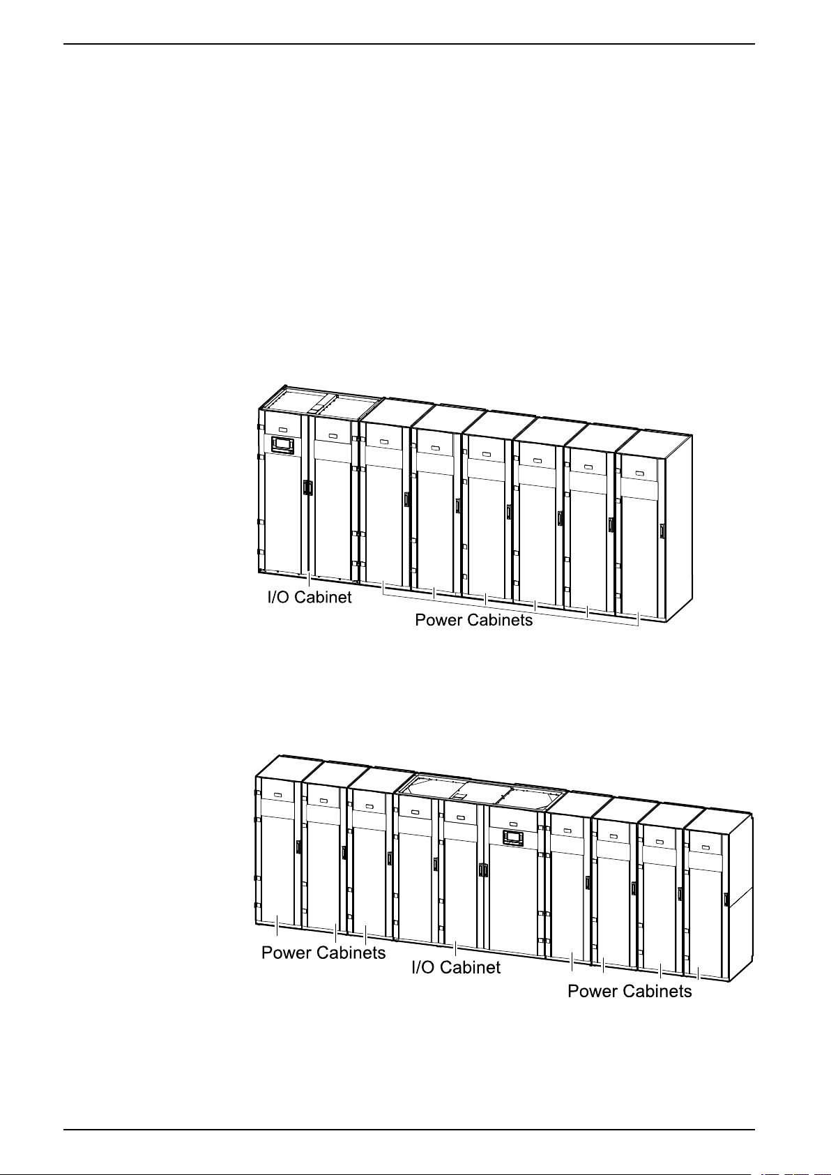
Each Galaxy VX UPS consists of the following components:
• An I/O cabinet for wield wiring containing the static switch, a backfeed
protection switch, and the user interface.
• A number of 250 kW power cabinets containing the power electronics.
UPSs with 1250 kW I/O Cabinet
The 1250 kW I/O cabinet is used for UPS systems from a minimum configuration
of 500 kW with two power cabinets to a maximum configuration of 1250 kW N+1
with six power cabinets. The I/O cabinet is placed to the left and two to six power
cabinets (depending on system size) are placed to the right. The image below
shows the maximum configuration.
UPSs with 1500 kW I/O Cabinet
The 1500 kW I/O cabinet is used for UPS systems from a minimum configuration
of 500 kW with two power cabinets to a maximum configuration of 1500 kW N+1
with seven power cabinets. The image below shows the maximum configuration.
8 990-5850F-001

Technical Data 380 V, 400 V, 415 V, and 440 V UPS System
Model List
UPSs with 1250 kW I/O Cabinet
• GVX500K500NHS: Galaxy VX 500 kW, 400 V, start-up 5x8
• GVX500K750NHS: Galaxy VX 500 kW scalable to 750 kW 400 V, start-up
5x8
• GVX500K1000NHS: Galaxy VX 500 kW scalable to 1000 kW 400 V, start-up
5x8
• GVX500K1250NHS: Galaxy VX 500 kW scalable to 1250 kW 400 V, start-up
5x8
• GVX625K625NHS: Galaxy VX 625 kW, 400 V, start-up 5x8
• GVX625K1000NHS: Galaxy VX 625 kW scalable to 1000 kW 400 V, start-up
5x8
• GVX750K500NHS: Galaxy VX 500 kW N+1 redundant UPS 400 V, start-up
5x8
• GVX750K750NHS: Galaxy VX 750 kW, 400V, start-up 5x8
• GVX750K1000NHS: Galaxy VX 750 kW scalable to 1000 kW 400 V, start-up
5x8
• GVX750K1250NHS: Galaxy VX 750 kW scalable to 1250 kW 400 V, start-up
5x8
• GVX800K800NHS: Galaxy VX 800 kW, 400 V, start-up 5x8
• GVX1000K750NHS: Galaxy VX 750 kW N+1 redundant UPS 400 V, start-up
5x8
• GVX1000K1000NHS: Galaxy VX 1000 kW, 400 V, start-up 5x8
• GVX1000K1250NHS: Galaxy VX 1000 kW scalable to 1250 kW 400 V, startup 5x8
• GVX1100K1100NHS: Galaxy VX 1100 kW, 400 V, start-up 5x8
• GVX1250K1000NHS: Galaxy VX 1000 kW N+1 Redundant UPS 400 V, Startup 5x8
• GVX1250K1250NHS: Galaxy VX 1250 kW, 400 V, Start-up 5x8
• GVX1500K1100NHS: Galaxy VX 1100 kW N+1 Redundant UPS 400 V, Start
up 5x8
• GVX1500K1250NHS: Galaxy VX 1250 kW N+1 Redundant UPS 400 V, Startup 5x8
UPSs with 1500 kW I/O Cabinet
• GVX500K1500HS: Galaxy VX 500 kW 400 V scalable to 1500 kW, start-up
5x8
• GVX750K1500HS: Galaxy VX 750 kW 400 V scalable to 1500 kW, start-up
5x8
• GVX1000K1500HS: Galaxy VX 1000 kW 400 V scalable to 1500 kW, start-up
5x8
• GVX1250K1500HS: Galaxy VX 1250 kW 400 V scalable to 1500 kW, start-up
5x8
• GVX1500K1500HS: Galaxy VX 1500 kW 400 V, start-up 5x8
• GVX1750K1500HS: Galaxy VX 1500 kW 400 V N+1 redundant UPS, start-up
5x8
990-5850F-001 9
380 V, 400 V, 415 V, and 440 V UPS System Technical Data
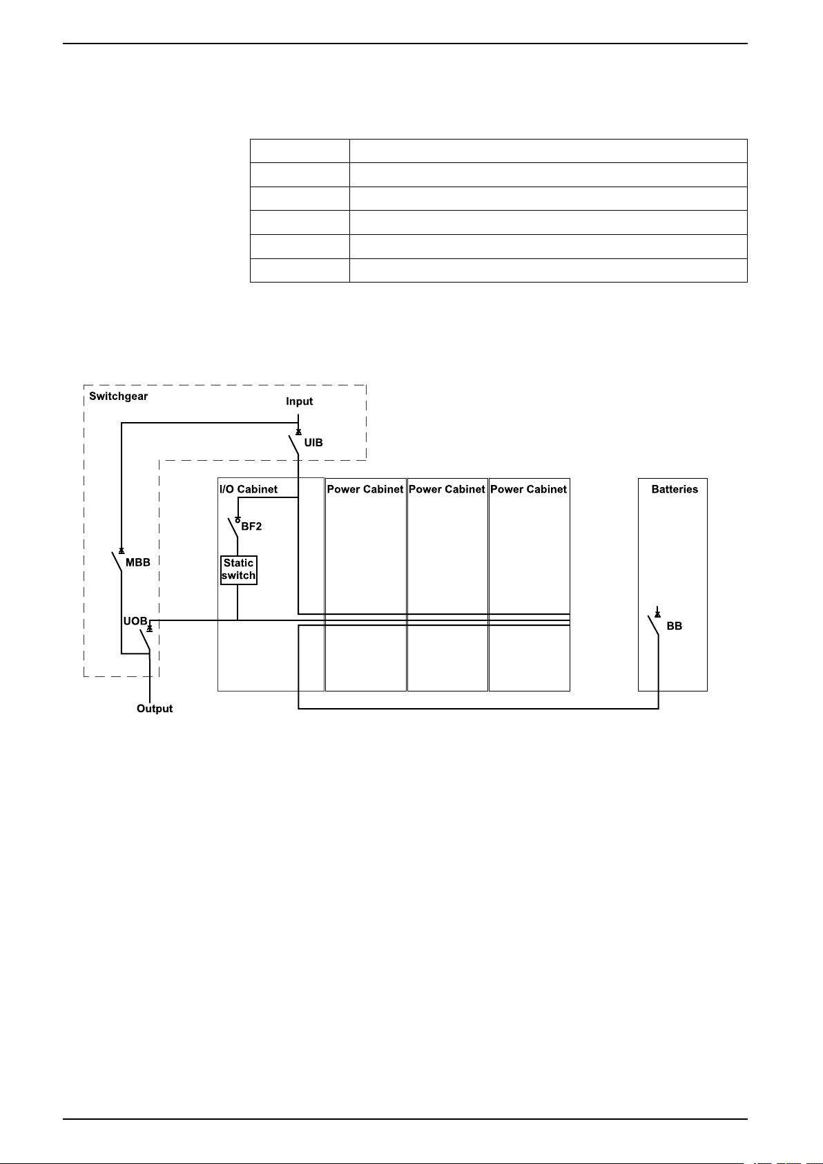
Overview of Configurations
Breakers in the System
UIB Unit input breaker
SSIB Static switch input breaker
BB Battery breaker
MBB Maintenance bypass breaker
UOB Unit output breaker
BF2 Backfeed protection switch
Overview of UPSs with 1250 kW I/O Cabinet - Single Utility/Mains
The illustration shows a 750 kW UPS. The principle is the same for the other
UPSs with the 1250 kW I/O cabinet.
10 990-5850F-001
Technical Data 380 V, 400 V, 415 V, and 440 V UPS System
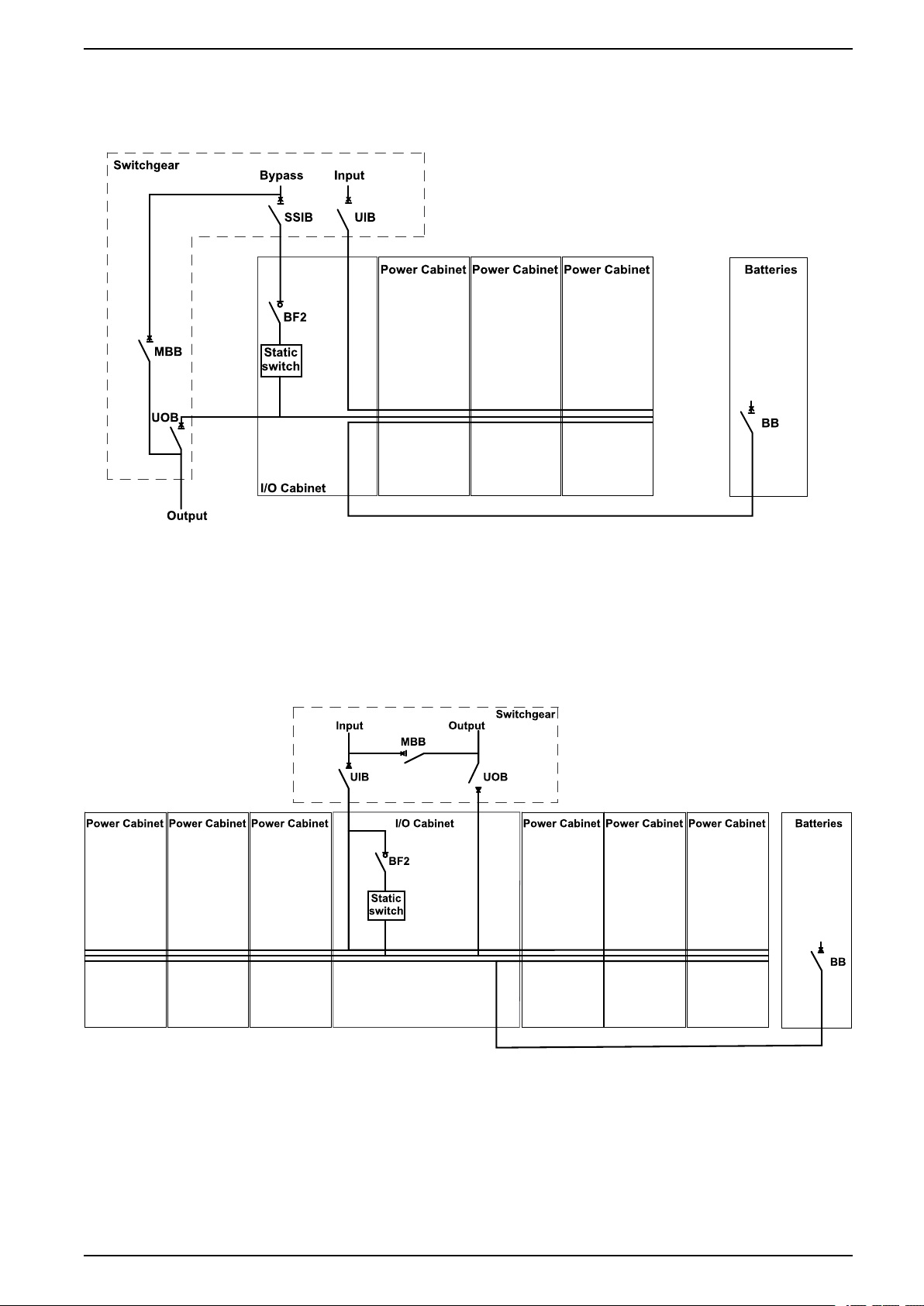
Overview of UPSs with 1250 kW I/O Cabinet - Dual Utility/Mains
The illustration shows a 750 kW UPS. The principle is the same for the other
UPSs with the 1250 kW I/O cabinet.
Overview of UPSs with 1500 kW I/O Cabinet – Single Utility/Mains
The illustration shows a 1500 kW UPS. The principle is the same for the other
UPSs with the 1500 kW I/O cabinet.
Galaxy VX 1500 kW UPS
990-5850F-001 11
380 V, 400 V, 415 V, and 440 V UPS System Technical Data
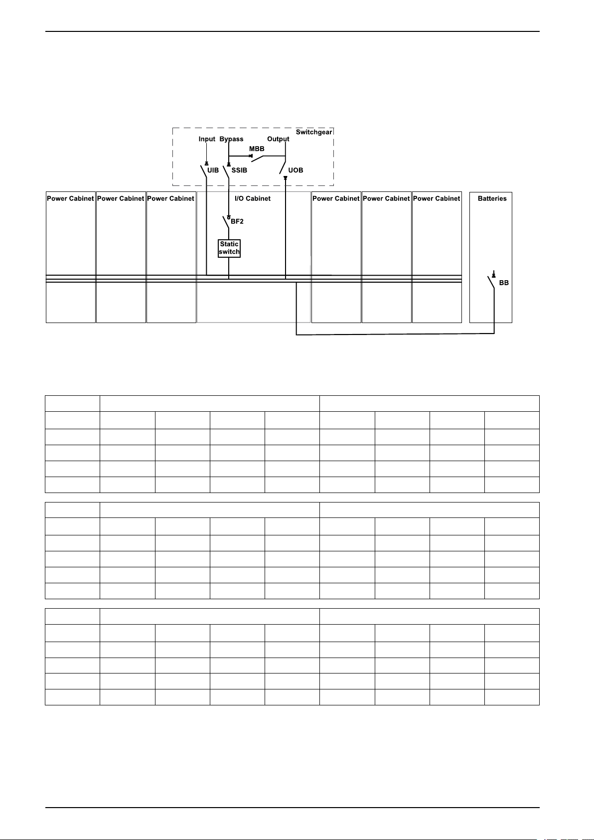
Overview of UPSs with 1500 kW I/O Cabinet – Dual Utility/Mains
The illustration shows a 1500 kW UPS. The principle is the same for the other
UPSs with the 1500 kW I/O cabinet.
Galaxy VX 1500 kW UPS
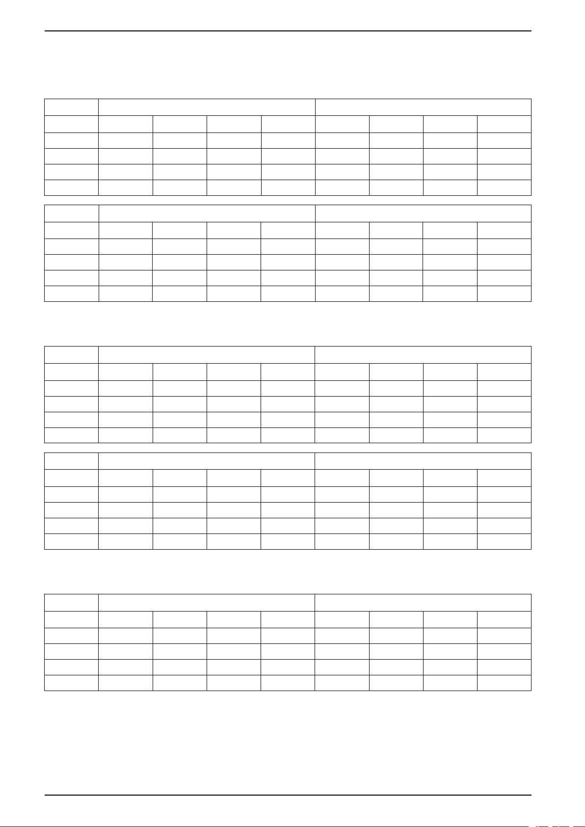
Input Power Factor
500 kW 625 kW
Voltage (V) 380 400 415 440 V 380 400 415 440 V
25% load 0.98 0.98 0.98 0.98 0.98 0.98 0.98 0.98
50% load 0.99 0.99 0.99 0.99 0.99 0.99 0.99 0.99
75% load 0.99 0.99 0.99 0.99 0.99 0.99 0.99 0.99
100% load 1.00 1.00 1.00 1.00 1.00 1.00 1.00 1.00
750 kW 800 kW
Voltage (V) 380 400 415 440 V 380 400 415 440 V
25% load 0.98 0.98 0.98 0.98 0.98 0.98 0.98 0.98
50% load 0.99 0.99 0.99 0.99 0.99 0.99 0.99 0.99
75% load 0.99 0.99 0.99 0.99 0.99 0.99 0.99 0.99
100% load 1.00 1.00 1.00 1.00 1.00 1.00 1.00 1.00
1000 kW 1100 kW
Voltage (V) 380 400 415 440 V 380 400 415 440 V
25% load 0.98 0.98 0.98 0.98 0.98 0.98 0.98 0.98
50% load 0.99 0.99 0.99 0.99 0.99 0.99 0.99 0.99
75% load 0.99 0.99 0.99 0.99 0.99 0.99 0.99 0.99
100% load 1.00 1.00 1.00 1.00 1.00 1.00 1.00 1.00
12 990-5850F-001
Technical Data 380 V, 400 V, 415 V, and 440 V UPS System
1250 kW 1500 kW
Voltage (V) 380 400 415 440 V 380 400 415 440 V
25% load 0.98 0.98 0.98 0.98 0.98 0.98 0.98 0.98
50% load 0.99 0.99 0.99 0.99 0.99 0.99 0.99 0.99
75% load 0.99 0.99 0.99 0.99 0.99 0.99 0.99 0.99
100% load 1.00 1.00 1.00 1.00 1.00 1.00 1.00 1.00
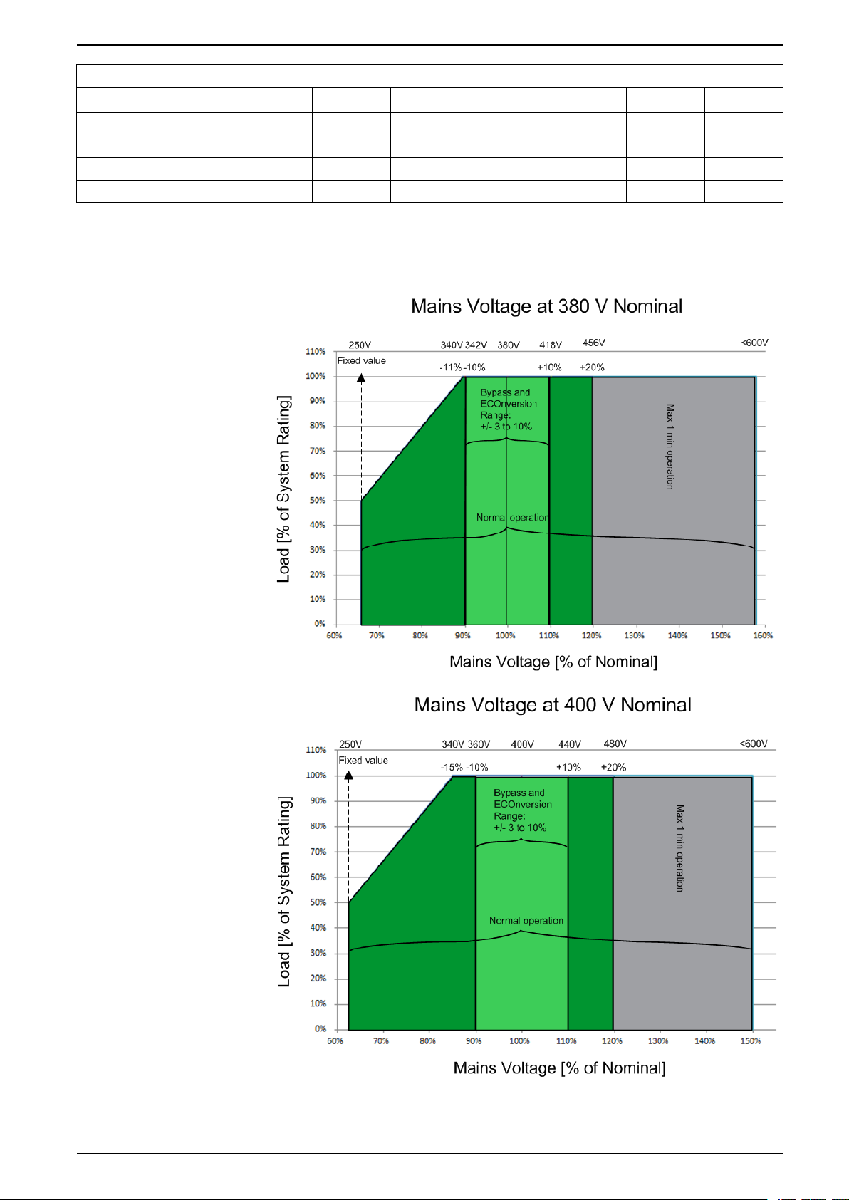
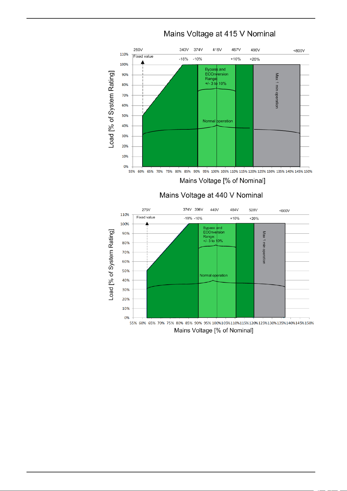
Input Voltage Window
990-5850F-001 13
380 V, 400 V, 415 V, and 440 V UPS System Technical Data
14 990-5850F-001
Technical Data 380 V, 400 V, 415 V, and 440 V UPS System
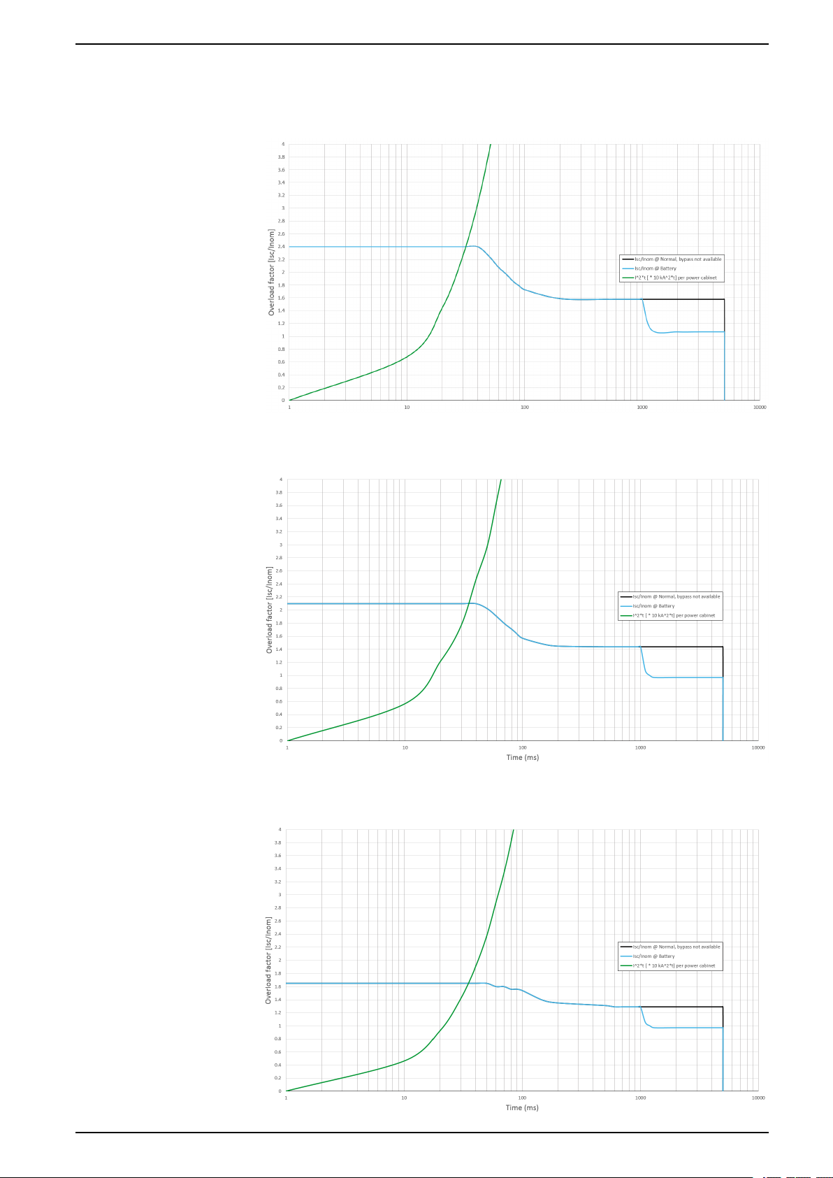
Inverter Short-Circuit Capabilities (Bypass not Available)
IK1 – Short-Circuit between a Phase and Neutral
IK2 – Short-Circuit between Two Phases
IK3 – Short-Circuit between All Three Phases
990-5850F-001 15
380 V, 400 V, 415 V, and 440 V UPS System Technical Data
Efficiency for UPSs with 1250 kW I/O Cabinet
Efficiency for a 500 kW UPS
Normal operation
Voltage (V) 380 400 415 440 V 380 400 415 440 V
25% load 96.0% 95.2% 95.2% 95.2% 97.4% 96.2% 96.3% 96.8%
50% load 96.1% 95.7% 95.7% 95.8% 99.0% 98.7% 98.8% 98.6%
75% load 95.8% 95.6% 95.6% 95.8% 99.0% 98.8% 98.8% 98.8%
100% load 95.6% 95.5% 95.6% 95.8% 99.2% 99.0% 99.0% 99.0%
ECOnversion
Voltage (V) 380 400 415 440 V 380 400 415 440 V
25% load 99.0% 98.3% 98.4% 97.7% 96.7% 96.5% 96.6% 96.6%
50% load 98.4% 98.5% 98.1% 98.2% 96.7% 96.7% 96.5% 96.5%
75% load 99.0% 98.9% 98.9% 98.8% 94.4% 96.4% 96.3% 96.3%
100% load 99.0% 99.2% 99.2% 99.1% 96.0% 95.8% 95.5% 95.5%
ECO mode
Battery operation
Efficiency for a 625 kW UPS
Normal operation
Voltage (V) 380 400 415 440 V 380 400 415 440 V
25% load 95.1% 95.2% 95.2% 95.2% 98.0% 97.6% 97.5% 97.5%
50% load 95.7% 95.7% 95.7% 96.0% 98.9% 98.7% 98.6% 98.6%
75% load 95.6% 95.6% 95.6% 96.0% 99.0% 98.8% 98.8% 98.8%
100% load 94.9% 95.5% 95.6% 95.9% 98.9% 98.8% 98.8% 98.9%
ECO mode
ECOnversion
Voltage (V) 380 400 415 440 V 380 400 415 440 V
25% load 97.1% 97.1% 98.0% 97.6% 96.9% 96.9% 96.6% 96.6%
50% load 98.4% 98.4% 98.4% 98.4% 96.3% 96.4% 96.5% 96.5%
75% load 98.7% 98.7% 98.7% 98.7% 96.3% 96.3% 96.3% 96.3%
100% load 98.8% 98.8% 98.8% 98.9% 96.1% 96.2% 95.5% 95.5%
Battery operation
Efficiency for a 750 kW UPS
Normal operation
Voltage (V) 380 400 415 440 V 380 400 415 440 V
25% load 95.7% 95.4% 95.4% 95.4% 98.4% 98.0% 97.9% 97.9%
50% load 95.8% 95.8% 95.9% 96.0% 98.9% 98.7% 98.6% 98.6%
75% load 95.3% 95.4% 95.7% 95.9% 99.0% 98.8% 98.8% 98.8%
100% load 94.6% 94.9% 95.2% 95.5% 99.0% 98.9% 98.9% 98.9%
ECO mode
16 990-5850F-001
Technical Data 380 V, 400 V, 415 V, and 440 V UPS System
ECOnversion
Voltage (V) 380 400 415 440 V 380 400 415 440 V
25% load 97.7% 97.7% 98.6% 98.2% 96.7% 96.7% 96.6% 96.6%
50% load 98.5% 98.5% 98.5% 98.5% 96.6% 96.7% 96.6% 96.6%
75% load 98.7% 98.7% 98.7% 98.7% 96.1% 96.2% 96.2% 96.2%
100% load 98.8% 98.8% 98.8% 98.9% 95.7% 95.8% 95.8% 95.8%
Battery operation
Efficiency for a 800 kW UPS
Normal operation
Voltage (V) 380 400 415 440 V 380 400 415 440 V
25% load 95.1% 95.1% 95.2% 95.2% 97.8% 97.8% 98.7% 98.7%
50% load 95.8% 95.9% 96.0% 96.1% 98.6% 98.6% 98.9% 98.9%
75% load 95.7% 95.8% 96.0% 96.1% 98.9% 98.9% 98.9% 98.9%
100% load 95.4% 95.5% 95.8% 96.1% 98.9% 99.0% 99.0% 99.0%
ECOnversion
Voltage (V) 380 400 415 440 V 380 400 415 440 V
25% load 97.5% 97.4% 97.5% 97.5% 96.2% 96.9% 97.0% 97.0%
50% load 98.5% 98.5% 98.5% 98.5% 96.4% 96.9% 96.6% 96.6%
75% load 98.8% 98.8% 98.8% 98.8% 96.3% 96.9% 96.8% 96.8%
100% load 98.9% 98.9% 99.0% 99.1% 96.0% 96.4% 96.3% 96.3%
ECO mode
Battery operation
Efficiency for a 1000 kW UPS
Normal operation
Voltage (V) 380 400 415 440 V 380 400 415 440 V
25% load 95.9% 95.6% 95.6% 95.6% 98.6% 98.2% 98.1% 98.1%
50% load 96.0% 96.0% 96.1% 96.1% 99.1% 98.9% 98.8% 98.8%
75% load 95.5% 95.6% 95.9% 95.9% 99.2% 99.0% 99.0% 99.0%
100% load 94.8% 95.1% 95.4% 95.4% 99.2% 99.1% 99.1% 99.1%
ECOnversion
Voltage (V) 380 400 415 440 V 380 400 415 440 V
25% load 97.9% 97.9% 98.8% 98.4% 96.8% 96.8% 96.7% 96.7%
50% load 98.7% 98.7% 98.7% 98.7% 96.7% 96.8% 96.7% 96.7%
75% load 98.9% 98.9% 98.9% 98.9% 96.2% 96.3% 96.3% 96.3%
100% load 99.0% 99.0% 99.0% 99.1% 95.8% 95.9% 95.9% 95.9%
ECO mode
Battery operation
990-5850F-001 17
 Loading...