

Page 1

ProWORX 32
Programming Software for PLCs
User Guide
372 SPU 780 01EMAN Version 1.0
31003882 00
Page 2

2
372 SPU 780 01EMAN May 2002
Page 3

Table of Contents
Safety Information . . . . . . . . . . . . . . . . . . . . . . . . . . . . . . . . . . . .9
About the Book. . . . . . . . . . . . . . . . . . . . . . . . . . . . . . . . . . . . . .11
Chapter 1 Getting Started . . . . . . . . . . . . . . . . . . . . . . . . . . . . . . . . . . . . . .13
Welcome to ProWORX 32. . . . . . . . . . . . . . . . . . . . . . . . . . . . . . . . . . . . . . . . . . 13
System Requirements. . . . . . . . . . . . . . . . . . . . . . . . . . . . . . . . . . . . . . . . . . . . . 14
Installing ProWORX 32. . . . . . . . . . . . . . . . . . . . . . . . . . . . . . . . . . . . . . . . . . . . 15
Logging in . . . . . . . . . . . . . . . . . . . . . . . . . . . . . . . . . . . . . . . . . . . . . . . . . . . . . . 16
Authorizing ProWORX 32 . . . . . . . . . . . . . . . . . . . . . . . . . . . . . . . . . . . . . . . . . . 17
The ProWORX 32 Environment . . . . . . . . . . . . . . . . . . . . . . . . . . . . . . . . . . . . . 19
ProWORX 32 Client Security . . . . . . . . . . . . . . . . . . . . . . . . . . . . . . . . . . . . . . . 20
Tracking Help . . . . . . . . . . . . . . . . . . . . . . . . . . . . . . . . . . . . . . . . . . . . . . . . . . . 22
ProWORX 32 Toolbar. . . . . . . . . . . . . . . . . . . . . . . . . . . . . . . . . . . . . . . . . . . . . 23
Contacting Schneider Electric. . . . . . . . . . . . . . . . . . . . . . . . . . . . . . . . . . . . . . . 26
Chapter 2 Working with Projects . . . . . . . . . . . . . . . . . . . . . . . . . . . . . . . .27
At a Glance . . . . . . . . . . . . . . . . . . . . . . . . . . . . . . . . . . . . . . . . . . . . . . . . . . . . . 27
Creating a New Project. . . . . . . . . . . . . . . . . . . . . . . . . . . . . . . . . . . . . . . . . . . . 29
Selecting a Controller Type. . . . . . . . . . . . . . . . . . . . . . . . . . . . . . . . . . . . . . . . . 31
Converting Ladder Logic Databases. . . . . . . . . . . . . . . . . . . . . . . . . . . . . . . . . . 34
Using the ProWORX Server to Manage ProWORX 32 Projects. . . . . . . . . . . . . 35
Working with a ProWORX 32 Project . . . . . . . . . . . . . . . . . . . . . . . . . . . . . . . . . 36
Using Emulation Mode . . . . . . . . . . . . . . . . . . . . . . . . . . . . . . . . . . . . . . . . . . . . 39
Instructions Supported in Emulation Mode . . . . . . . . . . . . . . . . . . . . . . . . . . . . . 45
Adding Emulation Instruction Solve Support. . . . . . . . . . . . . . . . . . . . . . . . . . . . 46
Documentation Editor . . . . . . . . . . . . . . . . . . . . . . . . . . . . . . . . . . . . . . . . . . . . . 51
Using the Documentation Editor . . . . . . . . . . . . . . . . . . . . . . . . . . . . . . . . . . . . . 53
Importing and Exporting ProWORX 32 Documentation . . . . . . . . . . . . . . . . . . . 55
Protected Registers. . . . . . . . . . . . . . . . . . . . . . . . . . . . . . . . . . . . . . . . . . . . . . . 58
Using Search. . . . . . . . . . . . . . . . . . . . . . . . . . . . . . . . . . . . . . . . . . . . . . . . . . . . 59
Address Used . . . . . . . . . . . . . . . . . . . . . . . . . . . . . . . . . . . . . . . . . . . . . . . . . . . 60
The Knowledge Base . . . . . . . . . . . . . . . . . . . . . . . . . . . . . . . . . . . . . . . . . . . . . 62
372 SPU 780 01EMAN May 2002 3
Page 4

Chapter 3 Communications Setup. . . . . . . . . . . . . . . . . . . . . . . . . . . . . . . 65
Connecting to a Controller. . . . . . . . . . . . . . . . . . . . . . . . . . . . . . . . . . . . . . . . . . 65
Communications Overview . . . . . . . . . . . . . . . . . . . . . . . . . . . . . . . . . . . . . . . . . 66
Configuring Modbus Communications . . . . . . . . . . . . . . . . . . . . . . . . . . . . . . . . . 67
Modbus Communications by Modem. . . . . . . . . . . . . . . . . . . . . . . . . . . . . . . . . . 68
Configuring Modbus Plus Communications. . . . . . . . . . . . . . . . . . . . . . . . . . . . . 71
Configuring Ethernet Gateway Communications. . . . . . . . . . . . . . . . . . . . . . . . . 72
Configuring TCP/IP Communications . . . . . . . . . . . . . . . . . . . . . . . . . . . . . . . . . 73
Network Explorer. . . . . . . . . . . . . . . . . . . . . . . . . . . . . . . . . . . . . . . . . . . . . . . . . 74
Chapter 4 Configuring a Controller . . . . . . . . . . . . . . . . . . . . . . . . . . . . . . 75
Controller Configuration. . . . . . . . . . . . . . . . . . . . . . . . . . . . . . . . . . . . . . . . . . . . 75
Controller Configuration. . . . . . . . . . . . . . . . . . . . . . . . . . . . . . . . . . . . . . . . . . . . 76
‘General’ Tab. . . . . . . . . . . . . . . . . . . . . . . . . . . . . . . . . . . . . . . . . . . . . . . . . . . . 77
‘Ports’ Tab . . . . . . . . . . . . . . . . . . . . . . . . . . . . . . . . . . . . . . . . . . . . . . . . . . . . . . 80
‘Loadables’ Tab . . . . . . . . . . . . . . . . . . . . . . . . . . . . . . . . . . . . . . . . . . . . . . . . . . 83
Loadable Library Wizard . . . . . . . . . . . . . . . . . . . . . . . . . . . . . . . . . . . . . . . . . . . 86
Chapter 5 Working with Controllers . . . . . . . . . . . . . . . . . . . . . . . . . . . . . 89
At a Glance . . . . . . . . . . . . . . . . . . . . . . . . . . . . . . . . . . . . . . . . . . . . . . . . . . . . . 89
Initializing Logic in a Controller . . . . . . . . . . . . . . . . . . . . . . . . . . . . . . . . . . . . . . 90
Reading From a Controller. . . . . . . . . . . . . . . . . . . . . . . . . . . . . . . . . . . . . . . . . . 91
Writing to a Controller . . . . . . . . . . . . . . . . . . . . . . . . . . . . . . . . . . . . . . . . . . . . . 92
Transferring Memory Contents to Controller EEPROM. . . . . . . . . . . . . . . . . . . . 94
Transferring the Flash RAM Executive . . . . . . . . . . . . . . . . . . . . . . . . . . . . . . . . 95
Transferring Memory Contents to Micro Flash RAM . . . . . . . . . . . . . . . . . . . . . . 96
Transferring Internal Flash or PCMCIA to Controller Flash. . . . . . . . . . . . . . . . . 97
Starting and Stopping Controllers . . . . . . . . . . . . . . . . . . . . . . . . . . . . . . . . . . . . 98
PLC Status Viewer. . . . . . . . . . . . . . . . . . . . . . . . . . . . . . . . . . . . . . . . . . . . . . . . 99
Analyze Device . . . . . . . . . . . . . . . . . . . . . . . . . . . . . . . . . . . . . . . . . . . . . . . . . 100
Chapter 6 Configuration Extensions. . . . . . . . . . . . . . . . . . . . . . . . . . . . 101
At a Glance . . . . . . . . . . . . . . . . . . . . . . . . . . . . . . . . . . . . . . . . . . . . . . . . . . . . 101
Configuration Extensions. . . . . . . . . . . . . . . . . . . . . . . . . . . . . . . . . . . . . . . . . . 102
Compact Phase II . . . . . . . . . . . . . . . . . . . . . . . . . . . . . . . . . . . . . . . . . . . . . . . 104
Data Protect Extension . . . . . . . . . . . . . . . . . . . . . . . . . . . . . . . . . . . . . . . . . . . 105
Quantum Hot Standby. . . . . . . . . . . . . . . . . . . . . . . . . . . . . . . . . . . . . . . . . . . . 106
IO Scanner. . . . . . . . . . . . . . . . . . . . . . . . . . . . . . . . . . . . . . . . . . . . . . . . . . . . . 108
IO Scanner Wizard. . . . . . . . . . . . . . . . . . . . . . . . . . . . . . . . . . . . . . . . . . . . . . . 111
Peer Cop . . . . . . . . . . . . . . . . . . . . . . . . . . . . . . . . . . . . . . . . . . . . . . . . . . . . . . 113
Peer Cop Wizard . . . . . . . . . . . . . . . . . . . . . . . . . . . . . . . . . . . . . . . . . . . . . . . . 118
Profibus Extension. . . . . . . . . . . . . . . . . . . . . . . . . . . . . . . . . . . . . . . . . . . . . . . 121
Profibus Wizard . . . . . . . . . . . . . . . . . . . . . . . . . . . . . . . . . . . . . . . . . . . . . . . . . 122
S980 Extension . . . . . . . . . . . . . . . . . . . . . . . . . . . . . . . . . . . . . . . . . . . . . . . . . 123
SY/MAX Extension. . . . . . . . . . . . . . . . . . . . . . . . . . . . . . . . . . . . . . . . . . . . . . . 124
TCP/IP Extension. . . . . . . . . . . . . . . . . . . . . . . . . . . . . . . . . . . . . . . . . . . . . . . . 125
4 372 SPU 780 01EMAN May 2002
Page 5

Quantum VME Bus Extension. . . . . . . . . . . . . . . . . . . . . . . . . . . . . . . . . . . . . . 126
Chapter 7 Using the Logic Editor . . . . . . . . . . . . . . . . . . . . . . . . . . . . . . .127
At a Glance . . . . . . . . . . . . . . . . . . . . . . . . . . . . . . . . . . . . . . . . . . . . . . . . . . . . 127
Logic Editor Overview. . . . . . . . . . . . . . . . . . . . . . . . . . . . . . . . . . . . . . . . . . . . 129
Logic Editor Properties . . . . . . . . . . . . . . . . . . . . . . . . . . . . . . . . . . . . . . . . . . . 130
Hotkey Template. . . . . . . . . . . . . . . . . . . . . . . . . . . . . . . . . . . . . . . . . . . . . . . . 132
Using the Logic Editor. . . . . . . . . . . . . . . . . . . . . . . . . . . . . . . . . . . . . . . . . . . . 135
Working with Networks . . . . . . . . . . . . . . . . . . . . . . . . . . . . . . . . . . . . . . . . . . . 138
Instructions . . . . . . . . . . . . . . . . . . . . . . . . . . . . . . . . . . . . . . . . . . . . . . . . . . . . 140
Working with Addresses . . . . . . . . . . . . . . . . . . . . . . . . . . . . . . . . . . . . . . . . . . 142
Configurable Mnemonics. . . . . . . . . . . . . . . . . . . . . . . . . . . . . . . . . . . . . . . . . . 144
ISA Symbols . . . . . . . . . . . . . . . . . . . . . . . . . . . . . . . . . . . . . . . . . . . . . . . . . . . 146
Diagnostic Trace. . . . . . . . . . . . . . . . . . . . . . . . . . . . . . . . . . . . . . . . . . . . . . . . 148
Sweep (Online Only). . . . . . . . . . . . . . . . . . . . . . . . . . . . . . . . . . . . . . . . . . . . . 149
Setting Bookmarks in Logic. . . . . . . . . . . . . . . . . . . . . . . . . . . . . . . . . . . . . . . . 151
Hardware Clock. . . . . . . . . . . . . . . . . . . . . . . . . . . . . . . . . . . . . . . . . . . . . . . . . 152
Segment Scheduler. . . . . . . . . . . . . . . . . . . . . . . . . . . . . . . . . . . . . . . . . . . . . . 153
Equation Networks . . . . . . . . . . . . . . . . . . . . . . . . . . . . . . . . . . . . . . . . . . . . . . 154
Mathematical Equations in Equation Networks. . . . . . . . . . . . . . . . . . . . . . . . . 156
Mathematical Operations in Equation Networks. . . . . . . . . . . . . . . . . . . . . . . . 158
Mathematical Functions in Equation Networks. . . . . . . . . . . . . . . . . . . . . . . . . 161
Chapter 8 Using the Traffic Cop . . . . . . . . . . . . . . . . . . . . . . . . . . . . . . . .163
At a Glance . . . . . . . . . . . . . . . . . . . . . . . . . . . . . . . . . . . . . . . . . . . . . . . . . . . . 163
Traffic Cop Overview. . . . . . . . . . . . . . . . . . . . . . . . . . . . . . . . . . . . . . . . . . . . . 164
Working with Drops and Racks. . . . . . . . . . . . . . . . . . . . . . . . . . . . . . . . . . . . . 165
Working with Slots. . . . . . . . . . . . . . . . . . . . . . . . . . . . . . . . . . . . . . . . . . . . . . . 167
Online Module Status . . . . . . . . . . . . . . . . . . . . . . . . . . . . . . . . . . . . . . . . . . . . 169
I/O Drawing Generator . . . . . . . . . . . . . . . . . . . . . . . . . . . . . . . . . . . . . . . . . . . 171
Materials List. . . . . . . . . . . . . . . . . . . . . . . . . . . . . . . . . . . . . . . . . . . . . . . . . . . 172
Chapter 9 Using the Data Watch Window . . . . . . . . . . . . . . . . . . . . . . . .175
At a Glance . . . . . . . . . . . . . . . . . . . . . . . . . . . . . . . . . . . . . . . . . . . . . . . . . . . . 175
Data Watch Window Overview . . . . . . . . . . . . . . . . . . . . . . . . . . . . . . . . . . . . . 177
Properties . . . . . . . . . . . . . . . . . . . . . . . . . . . . . . . . . . . . . . . . . . . . . . . . . . . . . 181
HMI . . . . . . . . . . . . . . . . . . . . . . . . . . . . . . . . . . . . . . . . . . . . . . . . . . . . . . . . . . 184
Trend. . . . . . . . . . . . . . . . . . . . . . . . . . . . . . . . . . . . . . . . . . . . . . . . . . . . . . . . . 188
Trend - Mode Functionality Table . . . . . . . . . . . . . . . . . . . . . . . . . . . . . . . . . . . 190
Track Logic Editor. . . . . . . . . . . . . . . . . . . . . . . . . . . . . . . . . . . . . . . . . . . . . . . 191
Track Traffic Cop. . . . . . . . . . . . . . . . . . . . . . . . . . . . . . . . . . . . . . . . . . . . . . . . 192
Instruction Editor / Terminal Block Editor . . . . . . . . . . . . . . . . . . . . . . . . . . . . . 193
Instruction / Terminal Block Editor Display Scripts . . . . . . . . . . . . . . . . . . . . . . 194
Display Script Variables . . . . . . . . . . . . . . . . . . . . . . . . . . . . . . . . . . . . . . . . . . 195
Display Script Functions . . . . . . . . . . . . . . . . . . . . . . . . . . . . . . . . . . . . . . . . . . 196
Register Editor. . . . . . . . . . . . . . . . . . . . . . . . . . . . . . . . . . . . . . . . . . . . . . . . . . 201
372 SPU 780 01EMAN May 2002 5
Page 6

PID Tuner. . . . . . . . . . . . . . . . . . . . . . . . . . . . . . . . . . . . . . . . . . . . . . . . . . . . . . 202
DRUM Summary . . . . . . . . . . . . . . . . . . . . . . . . . . . . . . . . . . . . . . . . . . . . . . . . 205
Importing and Exporting Data Watch Window Data. . . . . . . . . . . . . . . . . . . . . . 207
Chapter 10 Working with the ASCII Editor . . . . . . . . . . . . . . . . . . . . . . . . 209
ASCII Editor. . . . . . . . . . . . . . . . . . . . . . . . . . . . . . . . . . . . . . . . . . . . . . . . . . . . 209
Chapter 11 Working with Macros. . . . . . . . . . . . . . . . . . . . . . . . . . . . . . . . 213
At a Glance . . . . . . . . . . . . . . . . . . . . . . . . . . . . . . . . . . . . . . . . . . . . . . . . . . . . 213
Macros. . . . . . . . . . . . . . . . . . . . . . . . . . . . . . . . . . . . . . . . . . . . . . . . . . . . . . . . 214
Using Macros in Logic . . . . . . . . . . . . . . . . . . . . . . . . . . . . . . . . . . . . . . . . . . . . 216
Chapter 12 ProWORX 32 Utilities. . . . . . . . . . . . . . . . . . . . . . . . . . . . . . . . 219
At a Glance . . . . . . . . . . . . . . . . . . . . . . . . . . . . . . . . . . . . . . . . . . . . . . . . . . . . 219
BM85 Setup. . . . . . . . . . . . . . . . . . . . . . . . . . . . . . . . . . . . . . . . . . . . . . . . . . . . 220
BootP Server . . . . . . . . . . . . . . . . . . . . . . . . . . . . . . . . . . . . . . . . . . . . . . . . . . . 223
Compare Utility . . . . . . . . . . . . . . . . . . . . . . . . . . . . . . . . . . . . . . . . . . . . . . . . . 226
I/O Drawing Viewer . . . . . . . . . . . . . . . . . . . . . . . . . . . . . . . . . . . . . . . . . . . . . . 228
The Ping Utility. . . . . . . . . . . . . . . . . . . . . . . . . . . . . . . . . . . . . . . . . . . . . . . . . . 229
MBP Stat . . . . . . . . . . . . . . . . . . . . . . . . . . . . . . . . . . . . . . . . . . . . . . . . . . . . . . 230
Chapter 13 ProWORX 32 Reporting. . . . . . . . . . . . . . . . . . . . . . . . . . . . . . 233
Reporting. . . . . . . . . . . . . . . . . . . . . . . . . . . . . . . . . . . . . . . . . . . . . . . . . . . . . . 233
Chapter 14 ProWORX 32 Server. . . . . . . . . . . . . . . . . . . . . . . . . . . . . . . . . 239
At a Glance . . . . . . . . . . . . . . . . . . . . . . . . . . . . . . . . . . . . . . . . . . . . . . . . . . . . 239
Using the ProWORX 32 Server. . . . . . . . . . . . . . . . . . . . . . . . . . . . . . . . . . . . . 240
Audit Trail. . . . . . . . . . . . . . . . . . . . . . . . . . . . . . . . . . . . . . . . . . . . . . . . . . . . . . 243
Chapter 15 Schneider Alliances. . . . . . . . . . . . . . . . . . . . . . . . . . . . . . . . . 245
At a Glance . . . . . . . . . . . . . . . . . . . . . . . . . . . . . . . . . . . . . . . . . . . . . . . . . . . . 245
Using the Schneider Alliances Tool. . . . . . . . . . . . . . . . . . . . . . . . . . . . . . . . . . 246
Using the Script Editor. . . . . . . . . . . . . . . . . . . . . . . . . . . . . . . . . . . . . . . . . . . . 249
Using Script Editor Controls. . . . . . . . . . . . . . . . . . . . . . . . . . . . . . . . . . . . . . . . 252
Appendices . . . . . . . . . . . . . . . . . . . . . . . . . . . . . . . . . . . . . . . . . . . . . .255
At a Glance . . . . . . . . . . . . . . . . . . . . . . . . . . . . . . . . . . . . . . . . . . . . . . . . . . . . 255
Appendix A I/O Cards. . . . . . . . . . . . . . . . . . . . . . . . . . . . . . . . . . . . . . . . . . 257
At a Glance . . . . . . . . . . . . . . . . . . . . . . . . . . . . . . . . . . . . . . . . . . . . . . . . . . . . 257
800. . . . . . . . . . . . . . . . . . . . . . . . . . . . . . . . . . . . . . . . . . . . . . . . . . . . . . . . . . . 258
A120. . . . . . . . . . . . . . . . . . . . . . . . . . . . . . . . . . . . . . . . . . . . . . . . . . . . . . . . . . 261
Compact TSX. . . . . . . . . . . . . . . . . . . . . . . . . . . . . . . . . . . . . . . . . . . . . . . . . . . 263
Micro . . . . . . . . . . . . . . . . . . . . . . . . . . . . . . . . . . . . . . . . . . . . . . . . . . . . . . . . . 265
Momentum M1 and INTERBUS. . . . . . . . . . . . . . . . . . . . . . . . . . . . . . . . . . . . . 266
Quantum . . . . . . . . . . . . . . . . . . . . . . . . . . . . . . . . . . . . . . . . . . . . . . . . . . . . . . 267
Sy/Max. . . . . . . . . . . . . . . . . . . . . . . . . . . . . . . . . . . . . . . . . . . . . . . . . . . . . . . . 270
6 372 SPU 780 01EMAN May 2002
Page 7

Appendix B Troubleshooting . . . . . . . . . . . . . . . . . . . . . . . . . . . . . . . . . . . .271
Troubleshooting. . . . . . . . . . . . . . . . . . . . . . . . . . . . . . . . . . . . . . . . . . . . . . . . . 271
B.1 General Troubleshooting. . . . . . . . . . . . . . . . . . . . . . . . . . . . . . . . . . . . . . . . . . 272
Section Overview . . . . . . . . . . . . . . . . . . . . . . . . . . . . . . . . . . . . . . . . . . . . . . . 272
Isolating Faults . . . . . . . . . . . . . . . . . . . . . . . . . . . . . . . . . . . . . . . . . . . . . . . . . 273
Manual Procedure List . . . . . . . . . . . . . . . . . . . . . . . . . . . . . . . . . . . . . . . . . . . 274
Modbus Plus . . . . . . . . . . . . . . . . . . . . . . . . . . . . . . . . . . . . . . . . . . . . . . . . . . . 276
Stopcode Error Analysis . . . . . . . . . . . . . . . . . . . . . . . . . . . . . . . . . . . . . . . . . . 277
B.2 Status Words for S901 and S908 . . . . . . . . . . . . . . . . . . . . . . . . . . . . . . . . . . . 280
At a Glance . . . . . . . . . . . . . . . . . . . . . . . . . . . . . . . . . . . . . . . . . . . . . . . . . . . . 280
ASCII Message Status . . . . . . . . . . . . . . . . . . . . . . . . . . . . . . . . . . . . . . . . . . . 281
Cable A Errors. . . . . . . . . . . . . . . . . . . . . . . . . . . . . . . . . . . . . . . . . . . . . . . . . . 282
Cable B Errors. . . . . . . . . . . . . . . . . . . . . . . . . . . . . . . . . . . . . . . . . . . . . . . . . . 283
Communication Status . . . . . . . . . . . . . . . . . . . . . . . . . . . . . . . . . . . . . . . . . . . 284
Controller State. . . . . . . . . . . . . . . . . . . . . . . . . . . . . . . . . . . . . . . . . . . . . . . . . 286
Controller Status . . . . . . . . . . . . . . . . . . . . . . . . . . . . . . . . . . . . . . . . . . . . . . . . 287
EOL (End of Logic) Pointer. . . . . . . . . . . . . . . . . . . . . . . . . . . . . . . . . . . . . . . . 288
Global Errors. . . . . . . . . . . . . . . . . . . . . . . . . . . . . . . . . . . . . . . . . . . . . . . . . . . 289
S911 Hot Standby Status (S908) . . . . . . . . . . . . . . . . . . . . . . . . . . . . . . . . . . . 290
Local Drop Communications Errors (S908). . . . . . . . . . . . . . . . . . . . . . . . . . . . 291
Machine Configuration . . . . . . . . . . . . . . . . . . . . . . . . . . . . . . . . . . . . . . . . . . . 292
Module Health. . . . . . . . . . . . . . . . . . . . . . . . . . . . . . . . . . . . . . . . . . . . . . . . . . 293
Number of Segments . . . . . . . . . . . . . . . . . . . . . . . . . . . . . . . . . . . . . . . . . . . . 295
Status Word Pointer Table . . . . . . . . . . . . . . . . . . . . . . . . . . . . . . . . . . . . . . . . 296
RIO Time-out. . . . . . . . . . . . . . . . . . . . . . . . . . . . . . . . . . . . . . . . . . . . . . . . . . . 297
Run/Load/Debug Status . . . . . . . . . . . . . . . . . . . . . . . . . . . . . . . . . . . . . . . . . . 298
S901/J200 Status . . . . . . . . . . . . . . . . . . . . . . . . . . . . . . . . . . . . . . . . . . . . . . . 299
S908 Errors. . . . . . . . . . . . . . . . . . . . . . . . . . . . . . . . . . . . . . . . . . . . . . . . . . . . 300
Stopcode. . . . . . . . . . . . . . . . . . . . . . . . . . . . . . . . . . . . . . . . . . . . . . . . . . . . . . 301
Appendix C Editing .DIF Files with Microsoft Excel. . . . . . . . . . . . . . . . . .303
Editing .DIF files with Microsoft Excel. . . . . . . . . . . . . . . . . . . . . . . . . . . . . . . . 303
Glossary . . . . . . . . . . . . . . . . . . . . . . . . . . . . . . . . . . . . . . . . . . . . . 307
Index . . . . . . . . . . . . . . . . . . . . . . . . . . . . . . . . . . . . . . . . . . . . . 321
372 SPU 780 01EMAN May 2002 7
Page 8

8 372 SPU 780 01EMAN May 2002
Page 9
Safety Information
§
Important Information
NOTICE Read these instructi ons carefully , and look a t the equipm ent to become fa miliar with
the device before trying to install, operate, or maintain it. The following special
messages may appear th roug hout thi s docu menta tion or on the equi pment to warn
of potential hazards or to call attention to information that clarifies or simplifies a
procedure.
The addition of this symb ol to a Danger or Warning safety labe l indicates
that an electrical hazard exists, which will result in personal injury if the
instructions are not foll owed.
This is the safety alert symbol. It is used to alert you to potential personal
injury hazards. Obey all safety messages that follow this symbol to avoid
possible injury or death.
DANGER
DANGER indicates an imminently hazardous situation, which, if not avoided, will
result in death, serious in ju ry , or equipment damage.
WARNING
WARNING indicates a potentially hazardous situation, which, if not avoided, can result
in death, serious injury , or equipment damage.
CAUTION
CAUTION indicates a potentially hazardous situation, which, if not avoided, can result
in injury or equipment d am age.
372 SPU 780 01EMAN May 2002 9
Page 10

Safety Information
PLEASE NOTE Electrical equipment should be serviced only by qualified personnel. No responsi-
bility is assumed by Schneider El ect ric for an y cons equen ces ari sing o ut of the u se
of this material. Thi s document is not intende d as an instruction manual for untrained
persons.
© 2002 Schneider Electric All Rights Reserved
10
372 SPU 780 01EMAN May 2002
Page 11

About the Book
At a Glance
Document Scope This manual describes how to install, c onf igu r e a nd us e Pro WO RX 32 and all of its
components.
To find out about any changes to the manual after this version was published,
consult our web site at public.modicon.com.
Terms and Abbreviations
Numbers are written according to international practice as well as according to
approved SI (System International d’Unites) presentation; each thousand is
separated by a space, along with use of the decimal point, e.g., 12 345.67
Validity Note This document applies to the installation and use of ProWORX 32 in Windows 98,
Windows Me, Windows XP, Windows NT 4.0, and Windows 2000 environments and
ProWORX Server in Windows XP, Windows NT 4.0, and Windows 2000
environments.
Related
Documents
Title of Documentation Reference Number
Modicon Ladder Logic Block Library 840 USE 101 00
Modicon Modbus Plus PCI-85 Interface Adapter 890 USE 162 00
Modicon Quantum Hot Standby System Planning and Installation
Guide
Modicon TSX Quantum Automation Series Hardware Reference
Guide
TSX Momentum I/O Base User Guide 870 USE 002 00
Modicon A120 Series I/O Modules User Guide 890 USE 109 00
BM85 Bridge Multiplexer User’s Guide 890 USE 103 00
840 USE 106 00
840 USE 100 00
372 SPU 780 01EMAN May 2002 11
Page 12

About the Book
Product Related
Warnings
Schneider Electric assumes no res po ns ibi lit y for an y errors that may appear in this
document. If you have any suggestions for improvements or amendments or have
found errors in this publication, please notify us.
No part of this document may be reproduced in any form or by any means, electron ic
or mechanical, including photocopying, without the express written permission of
Schneider Electric. All rights reserved. Copyright 2002.
User Comments We welcome your comments about this document. You can reach us by e-mail at
TECHCOMM@modicon.com
12
372 SPU 780 01EMAN May 2002
Page 13

Getting Started
Welcome to ProWORX 32
About this
Manual
Getting Started
with
ProWORX 32
What’s in this
Chapter?
This manual is a guide for operating ProWORX 32. It does not contain information
about specific controllers, I/O cards, or ladder logic instructions. For further
hardware and ladder logic info rma tio n, go to the ProWO R X 32 on -li ne he lp syste m.
This chapter guides you through starting out with ProWORX 32.
This chapter contains the following topics:
Topic Page
System Requirements 14
Installing ProWORX 32 15
Logging In 16
Authorizing ProWORX 32 17
The ProWORX 32 Environment 19
ProWORX 32 Client Security 20
Tracking Help 22
ProWORX 32 Toolbar 23
Contacting Schneider Electric 26
372 SPU 780 01EMAN May 2002 13
Page 14

Getting Started
System Requirements
Hardware
Requirements
Software
Requirements
Hardware:
Hardware Requirement
Processor P200
Memory 128 MB
Hard Disk Space (Available) 200 MB
Installation Media Type CD
Display 256 color VGA or higher
Software:
Software Requirement
ProWORX 32 Client Operating Systems
ProWORX Server - Operating
Systems
Microsoft Internet Explorer Version 5.0 or higher.
Microsoft MDAC Version 2.5 or higher.
Windows 98, Windows NT (Version 4.0, SP5 or higher),
Windows 2000, Window Me, and Windows XP.
Windows NT (Version 4.0, SP5 or higher), Windows 2000,
and Windows XP.
14
372 SPU 780 01EMAN May 2002
Page 15

Installing ProWORX 32
Getting Started
Installing
ProWORX 32
Modifying or
Repairing the
ProWORX 32
Installation
Uninstalling
(Removing)
ProWORX 32
ProWORX 32 requires the installation of MDac version 2.5 or great er and Internet
Explorer 5.0 or greater. Install the MDac software from the ProWORX 32 installation
CD, and ensure that you have a compatible version of Internet Explorer prior to
installing ProWORX 32. Then, to install ProWORX 32:
Step Action
1 Insert the ProWORX 32 CD into your CD-ROM drive. The ProWORX 32
installation screen should automatically load. If the ProWORX installation
program does not automatically load, you can open the installation in Windows
Explorer at CD Rom Drive
2 Select the Language you want to install ProWORX 32 in. (English, French,
German, Spanish.)
3 Follow the on-screen instructions to complete the installation of ProWORX 32.
→ Setup.exe.
If you have already installed ProWORX 32:
Step Action
1 Insert the ProWORX 32 CD into your CD-ROM drive.
2 Select Modify to add new components, or remove already installed components.
Click Next and follow the on-screen instructions.
3 Select Repair to reinstall all components installed by the previous setup. Click
Next and follow the on-screen instructions.
If you have already installed ProWORX 32:
Step Action
1 Insert the ProWORX 32 CD into your CD-ROM drive.
2 Select Remove to uninstall all installed components.
3 Click Next and follow the on-screen instructions.
372 SPU 780 01EMAN May 2002 15
Page 16

Getting Started
Logging In
The ProWORX 32
Login Screen
Logging In to the
ProWORX 32
Server
Logging Out of
the ProWORX 32
Server
When opening ProWORX 32 you are pro mpted with the ProWORX 32 Login sc reen.
If you are using project s that reside on a server or you w ant to communicate through
the server, enter the login informa tion and click Login. If you are us ing onl y projec ts
that reside on the client, click Bypass.
To access th e login screen from within ProWORX 32:
Step Action
1 In the ProWORX 32 menu, select File
2 Enter the user name and password that your system administrator has given you
in the Name and Password fields.
3 Select your method of communicating with the server from TCP/IP and Modbus
Plus.
4 Enter the address of the server in the Server Address field.
5 Enter the timeout (seconds) in the Timeout field.
6 If you have selected TCP/IP, enter the port number in the Port Number field.
7 If you have selected Modbus Plus, enter the adapter number in the Adapter
Number field.
8 Click Login.
→ Login.
Closing ProWORX 32 c li ent lo gs y ou out of the server or to l og ou t w hile remaining
in ProWORX 32:
Step Action
1 From the ProWORX 32 menu, select File
→ Logout.
16
372 SPU 780 01EMAN May 2002
Page 17
Authorizing ProWORX 32
Getting Started
Opening the
Authorization
Program
Using the
Authorization
Wizard
From the Windows Start menu:
Step Action
1 Select Programs
→ ProWORX 32 → Authorization.
After opening the authorization wizard:
Step Action
1 Select which task you would like to perform:
l
Authorize this PC: Sets up the PC you are currently using to run ProWORX
32.
l
Transfer Authorization: Transfers authorization from one PC to another.
l
Enter received code: If already registered, you are taken directly to the
Entering Authorization Code screen.
When you have made a selection, click Next.
2 Select which method you would prefer to authorize ProWORX 32 by, and click
Next:
l
Authorize by Phone: A message box is displayed containing a customer
support phone number and the customer support hours of operation. Click
OK to return to the authorization application.
l
Authorize by Fax: A fax page is printed containing the information you have
entered and a number to send the fax to.
l
Authorize by Multi-User License Diskette: This option is used strictly for
uncopyprotected versions in which a diskette has been provided by
Schneider Electric. The contents of the diskette will be transferred onto your
machine.
l
Authorize by Email: An email is sent to customer support containing the
information you have entered.
l
Authorize by W e b: You will be directed to a web page at the Schneider
Electric web site where the information that you have entered will be
displayed and an authorization number will be generated for you.
3 Select which product you want to authorize and click Next:
l
Online Only Client: Access to online only portions of ProWORX 32.
l
Lite Client: Access to Momentum, Compact, and Micro controllers only.
l
Full Development Client: Full access to all features of ProWORX 32.
l
Server: Full access to the ProWORX Server.
4 Enter all of your personal information in the User Information screen and click
Next. If you would like to view our privacy policy, click Privacy Policy.
372 SPU 780 01EMAN May 2002 17
Page 18

Getting Started
Moving
Authorization
Entering the
Authorization
Number
After selecting Transfer Authorization in Step One:
Step Action
1 Insert a diskette into your PC diskette drive.
2 Select which transaction you want to complete and click Next:
l
Transfer authorization from computer to diskette.
l
Transfer authorization from diskette to computer.
After receiving an authorization number:
Step Action
1A Code Entry Number and a Computer ID are created automatically
2 Enter the Authorization Number provided to you by customer support and click
Next.
3 To complete your ProWORX 32 authorization, click Finish.
18
372 SPU 780 01EMAN May 2002
Page 19

Getting Started
The ProWORX 32 Environment
Overview ProWORX 32 is organized i n s uch a w ay tha t the info rma tion you need at any time
is readily accessible through the ProWORX 32 main interface.
Setting
ProWORX 32
Properties
From the My Computer right-click menu in the Navigation panel:
Step Action
1 Select Properties.
2 Select the Environment tab.
3 Set the following ProWORX 32 Environment parameters:
4 Auto Monitor/Logout: When selected with Logout, the Online Network Editor
closes after the specified amount of inactive time. When selected with Monitor,
the Online Network Editor closes after the specified amount of inactive time and
Monitor mode is activated.
5 Prompt For Read When Exiting Online: Displays a prompt to perform a read
after switching out of online mode.
6 Compare To Project On Attach: Displays a prompt to perform a compare when
switching to online mode.
7 Enable Audit Trails : Audit trails and the log book are viewable.
8 Automatically Update Used Tables Online: When going online, the used
tables are automatically updated.
9 Enable Scrolling Nav igation Panel: When this option is selected, the
navigation panel shrinks showing only the panel’s border. To see the navigation
panel, hover your mouse over the border and the navigation panel expands.
10 Instruction Toolbar: See ProWORX 32 Toolbar, p. 23.
372 SPU 780 01EMAN May 2002 19
Page 20

Getting Started
ProWORX 32 Client Security
Overview Security allows an administrator to disable features of ProWORX 32.
Setting Security
for a Client
From the My Computer right-click menu in the Navigation panel:
Step Action
1 Select Security Settings to open the Client Security dialog.
2 To set and confirm the administrative password, enter the password into the
Password and Confirm Password boxes.
3 To set the rights that users have while running ProWORX 32 on this specific PC,
select rights from the Enabled Functionality group of rights. See User Rights
below for more information.
4 Click OK to confirm changes. Click Close to exit.
20
372 SPU 780 01EMAN May 2002
Page 21

User Rights User rights descriptions:
User Rights Descriptions
Controller Configuration The ability to change the controller configuration, or change
Traffic Cop The ability to edit in the traffic cop.
Communications The ability to change the communications setup including the
Logic The ability to edit logic.
Forcing The ability to force contacts and coils.
Insert The ability to insert cells, rows, columns, and networks.
Delete The ability to delete cells, rows, columns, and networks.
Sweep The ability to enter sweep mode.
Data Editors The ability to enter any of the data editors, If deselected, the
Extended Memory The ability to edit extended memory registers.
Protected Registers The ability to set ranges of 4xxxx addresses that are
Configuration Extensions The ability to edit the configuration extensions.
ASCII Messages The ability to edit the ASCII messages.
Search The ability to use the search feature.
Read The ability to read from the controller.
Write The ability to write to the controller.
Start/Stop The ability to start or stop the controller.
Clear Audit Trails The ability to remove all audit trail and logbook entries.
Getting Started
controller type.
controller’s address.
user is unable to change register data.
uneditable. See Setting Protected Registers for more
information.
372 SPU 780 01EMAN May 2002 21
Page 22

Getting Started
Tracking Help
Overview Tracking help is a brief desc ription or overv iew of the editor, ins tructions, or I/O card
that is curr ently selected in ProWORX 32.
Using Tracking
Help
From the ProWORX 32 menu:
Step Action
1 Select View
2 To see more information about the current tracking help topic, press F1.
→ Tracking Help to open the tracking help window.
22
372 SPU 780 01EMAN May 2002
Page 23

Getting Started
ProWORX 32 Toolbar
Overview The ProWORX 32 toolbar holds all of the icon buttons that can be used to access
features, utilities, and tools needed to properly use ProWORX 32s development
capabilities.
Using the
Toolbar
Customizing the
Instruction
Toolbar
Handle
ProWORX 32 Toolbar
From the ProWORX 32 toolbar right-click menu:
Step Action
1 To add a toolbar, select a toolbar to add from the list. A toolbar that is displayed
is denoted by a check .
2 To remove a toolbar, select a toolbar to remove from the list.
3 To move a selected toolbar within the ProWORX 32 toolbar area, select the
toolbars handle, and drag and drop the toolbar to its desired location.
4 To customize the toolbars, click Customize. To view help concerning toolbar
customizing please refer the Windows help file, Windows Start Menu
In the project navigation panel:
Step Action
1 From the project right-click menu, select Properties.
2 Select the Environment tab.
3 Scroll to the number of the button (1-14) you would like to change in the Button
Number field. eg. 1 = the leftmost button, 14 = the rightmost button.
4 Enter the name of the instruction to be placed on the toolbar in the Button Text
field.
→ Help.
372 SPU 780 01EMAN May 2002 23
Page 24
Getting Started
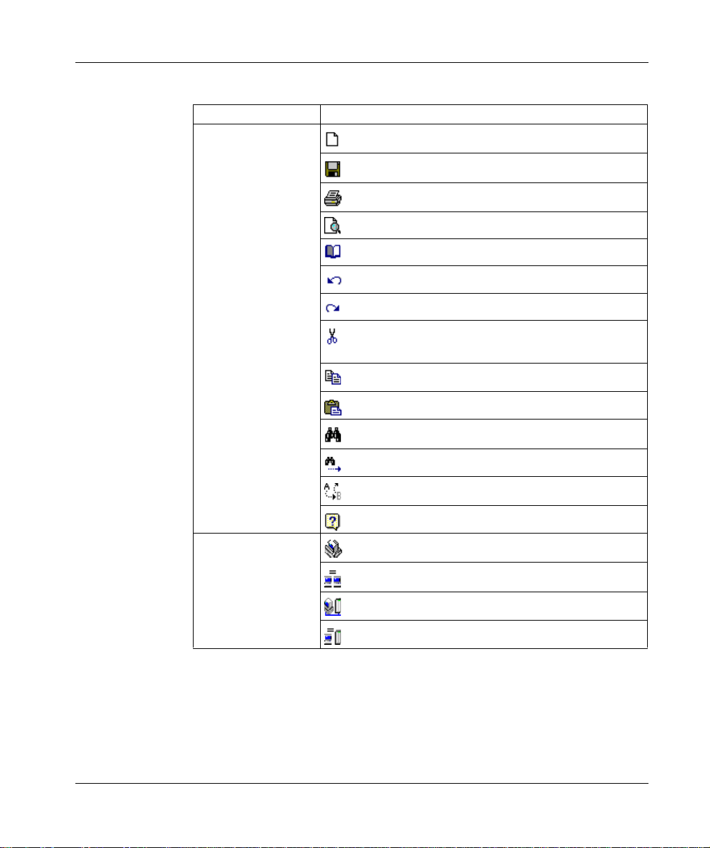
Toolbar Listing Default toolbars and items:
Toolbar Item
Standard Toolbar
(CTRL+X)
- Create a New Project
- Save the Active Project
- Print the Active Project
- Open Print Preview
- Open Report Setup
- Undo the most recent action (CTRL+Z)
- Repeats the most recent action
- Cut the current selection and copy to the system clipboard
- Copy the current selection to the system clipboard (CTRL+C)
- Paste data from system clipboard to selected area (CTRL+V)
- Open the Search window (CTRL+F)
24
Control Toolbar. See
Working with a
ProWORX 32 Project,
p. 36
- Repeat the last Search operation (SHIFT+F4)
- Find and Replace (CTRL+H)
- Open Help (F1)
- Take project offline
- Take project to emulation
- Take project online
- Take project to combined mode
372 SPU 780 01EMAN May 2002
Page 25
Toolbar Item
Online Control Toolbar
p. 98.
l
l
l
l
l
l
DWW Log Toolbar
Getting Started
- Start/Stop controller. See Starting and Stopping Controllers,
- Initialize logic. See Initializing Logic in a Controller, p. 90.
- Read from controller. See Reading From a Controller, p. 91.
Read
Read extended memory
- Write to controller. See Writing to a Controller, p. 92.
Write logic
Relocate logic and data
Relocate logic only
Write extended memory
- First record
- Previous record
- Next Record
- Last record
- Pause/Resume
- Record
- Toggle between logging real-time data from a controller and
logging stored
Instruction Toolbar
- A user-defined set of instructions. Clicking an instruction adds it
to the logic editor at the cursor.
372 SPU 780 01EMAN May 2002 25
Page 26

Getting Started
Contacting Schneider Electric
Contact
Information
Support
Guidelines
Customer support is available to registered Schneider Electric users.
If you have a question about ProWORX 32 and can’t find the answer in the
ProWORX 32 Help system or the User ’s Guid e, contact our Custom er Servic e staff
for assistance. You can reach Schneider’s Customer Support department by
Internet, phone, fax, or mail:
Schneider Electric
One High Street
North Andover, MA 01845
Internet: http://public.modicon.com/
E-mail: customercentral@schneiderautomation.com
Support Hotline: (888) 266-8705
Telephone: (978) 794-0800
Fax: (978) 975-9301
To help us assist you quickly, we sugge st yo u have the fol lowing inf ormati on read y:
l
The version and serial number of your copy of ProWORX 32. To find this
information, select About on the Help menu.
l
What you were doing when the p roblem occu rred, whether you can repe at it, and
any error messages you recei ve d.
l
Your version of Windows. To find this information in Windows ME, 98, 95, 2000
or NT 4.x: click Start, then Settings. Select Control Panel. When the Control
Panel window opens, double-click System. When the System window opens,
select the General tab. Your version of Windows is listed under the heading
System.
l
Information about your computer, inclu ding its processor type, memory, hard
drive size, video card type, and I/O boards.
26
372 SPU 780 01EMAN May 2002
Page 27

Working with Projects
At a Glance
Overview ProWORX 32 holds information about each of your controllers in a project. The
project stores:
l
The controller’s configuratio n
l
Ladder logic
l
Descriptors of the controller and ladder logic
l
Project properties
l
Data trends
l
Compare results
372 SPU 780 01EMAN May 2002 27
Page 28

Working with Projects
What’s in this
Chapter?
This chapter contains the following topics:
Topic Page
Creating a New Project 29
Selecting a Controller Type 31
Converting Ladder Logic Databases 34
Using the ProWORX Server to Manage ProWORX 32 Projects 35
Working with a ProWORX 32 Project 36
Using Emulation Mode 39
Instructions Supported in Emulation Mode 45
Adding Emulation Instruction Solve Support 46
Documentation Editor 51
Using the Documentation Editor 53
Importing and Exporting ProWORX 32 Documentation 55
Protected Registers 58
Using Search 59
Address Used 60
The Knowledge Base 62
28
372 SPU 780 01EMAN May 2002
Page 29

Creating a New Project
Working with Projects
Creating a New
Project
From the ProWORX 32 tool bar:
Step Action
1 Click File
2 Enter a project name in the New Project Name box.
3 Click OK. The New Project Wizard appears.
→ New.
Overview The Project Configuration Wizard steps you through creating new default projects
and modify existing projects in ProWORX 32. The configuration wizard guides you
through a series of easy to understand steps to set up a project. Each step
configures an important area of the project.
Each screen in the wizard has a caption stating which step you are currently
completing. Also, each screen has a diagram and description detailing what the
current step involves.
The standard wizard buttons are:
Button Function
Help Displays context-sensitive help pertaining to the current step.
Cancel Exits the wizard and no new project is created or no changes are saved.
Back Returns the wizard to the previous step.
Next Advances the wizard to the next step.
Finish Completes the wizard and creates a new project or saves the changes.
372 SPU 780 01EMAN May 2002 29
Page 30

Working with Projects
Step 1 - Select
Creation Method
Select a path to create a new project:
Path Description
Online to Controller This option sets up a project enough to go online to a controller.
The first step configures the parameters used to communicate
with the desired controller. This step encapsulates
communications setup; use of this step is identical to the Project
communications setup dialog. Click Next to display the Finish
step. Click Finish to go online to the desired controller.
Select Controller Type This step allows you to set up the controller type. For more
information, see Selecting a Controller Type, p. 31.
Base on Existing Project This option creates a project based on an existing project. First,
select an existing Project from the list of projects on the local
computer. ProWORX 32 creates a copy of the project and uses
it as the base for the new project. ProWORX 32 initializes the
logic and clears the traffic cop of the new project. ProWORX 32
then displays a communications setup step to configure
communications to the desired controller. On the finish step
click Finish to complete the new project creation.
Read from Controller This option creates a project based on a read of the program
from an existing controller. ProWORX 32 displays a
communications setup step to configure communications to the
desired controller. On the Finish step click Finish. ProWORX
32 reads the contents of the controller into a new default project.
Use as a Macro When selecting any offline options, you can click the Use as
Macro checkbox to create a macro-enabled database. For more
information, see Macros, p. 214.
30
372 SPU 780 01EMAN May 2002
Page 31

Selecting a Controller Type
Working with Projects
Selecting a
Controller Type
This step includes two drop dow n lists to se lect a contro ller. To the ri ght of the drop
down lists is a detailed description of the currently selected controller. Displayed
below the controlle r selection dr op down list are pictures of the I/O type(s) supported
by the current controller.
To select a controller:
Step Action
1 Select a controller family from the Pick a Controller Family drop-down box:
Compact, Micro, Momentum, 38x/48x, 484 Replacement, 68x/78x, 984ABX,
Atrium, Other, Quantum, or VME.
2 Select the desired controller from the Pick a Controller drop-down box. The list
of controllers depends on which controller family you selected in Step 1.
3 Click Next to continue.
372 SPU 780 01EMAN May 2002 31
Page 32

Working with Projects
Controller
Details
The controller details available depends on the controller you have selected in the
previous step. Set the available controller details:
Controller Detail Description
Executive Cartridge Cartridges which determine the controller’s instruction set.
Select the one installed in your controller. The Executive
Cartridge is available for some 38x, 48x, 68x and Quantum
controllers.
Memory Pack The amount of both Extended and User Logic memory in the
controller. Select the amount installed in your controller.
Available on a variety of x80 and 984 A/B controllers.
Extended Memory Additional mem ory providing 6xxx x registers. Selec t the
amount installed in your controller. Available on a variety of
x80 and 984 A/B controllers.
Built-in XMRD/XMWT Select Yes or No. The built-in extended memory functions
option is only available for the 984AS908.
User Logic Memory available for ladder logic. Select the amount of
memory you want to use for ladder logic from the total amount
available in your controller. Available on a variety of x80 and
984 A/B controllers.
S908 Size Select either 512 or 1024 (1k) input and output points per drop.
Available for most 68x and 78x controllers.
Micro I/O Mode Micro controllers only. Select:
l
Single: The controller is independent, not in a parent/child
relationship.
l
Parent: The controller is the parent in a parent/child
relationship.
l
Child: The controller is the child in a parent/child
relationship.
Available for "Brick" controllers from the Micro 311/0 to the
Micro 612/4.
32
Click Next when you have set the controller details.
372 SPU 780 01EMAN May 2002
Page 33

Working with Projects
Communications
Setup
To select a communications mode:
Step Action
1 Select a communications tab: Modbus, Modbus Plus, Gateway, or TCP/IP.
2 Set the communications-specific properties as desired. For more information
see Communications Overview, p. 66.
3 If your project will communicate with a controller via the ProWORX server, click
the Use server to communicate check box.
4 Click Next to continue.
Finish The finish step displays a summary of the selected controller type. Click Finish to
perform the operations set up in the previous steps. When the progress number
reaches 100% the wizard closes. The newly created project appears in the project
navigation tree.
372 SPU 780 01EMAN May 2002 33
Page 34

Working with Projects
Converting Ladder Logic Databases
Overview Old ladder logic databases created in 484, 884, ProWORX, ProWORX Plus,
ProWORX NxT, Modsoft, and Concept can be imported into the new format of
ProWORX 32. By importing a database using the ProWORX 32 convert function,
your logic, documentation, configuration, and other relevant areas of your project
are converted directly into ProWORX 32.
Converting a
Database
From the ProWORX 32 menu:
Step Action
1 Select File
appears.
2 Select a database to convert from the following database types:
l
l
l
l
l
l
3 When you have selected a database, click Open to start the conversion process.
4 To cancel the conversion, click Cancel in the Conversion Status dialog.
5 Click OK in the Conversion complete dialog to return to ProWORX 32.
→ Import Database. The Select Database to Convert dialog
484 databases - *.CF4
884 databases - *.CF8
Old ProWORX databases - *.CF9, *.DCF
Modsoft databases - *.CFG
Concept databases - *.ASC
ProWORX Plus/NxT databases - *.DCF
34
372 SPU 780 01EMAN May 2002
Page 35

Working with Projects
Using the ProWORX Server to Manage ProWORX 32 Projects
Overview The ProWORX Server is an application used to store and manage ProWORX 32
projects. The following project transactions can occur between a ProWORX 32
client, and the ProWORX Se rver. For more in formation about the ProWORX Server,
see ProWORX 32 Server, p. 239.
In the project navi gation panel of the ProWORX 32 client, fro m the projec t right-click
menu:
Transaction Result
Select Get from Server. The selected project is copied to your local PC. If you
plan to make changes to a project it is recommended
that you get the project from the server with a lock.
Select Get from Server with Lock. The selected project is copied to your local PC. You
have sole access and editing capabilities for a project
when it is locked out to your PC.
Select Put to Server. When you have finished making changes or you want
to add a project to the server, use the Put to Server
function. This function creates a copy of the project on
the server.
Select Unlock Project. The project is unlocked so that other clients can
check it out of the server.
372 SPU 780 01EMAN May 2002 35
Page 36

Working with Projects
Working with a ProWORX 32 Project
Projects in
Offline Mode
Taking a Project
Offline
Projects in
Online Mode
Taking a Project
Online
To work with a controll er offline, you must cre ate a p r oje ct for i t. Th is pro jec t s tore s
the controller’s traffic cop and configuration information, its ladder logic, and
descriptors of the controller and ladder logic. As you work in offline mode, editors
modify this data. Because the offline editors are not connected directly to the
controller, changes made in it do not take effect immediately. Instead, when you
have finished progra mming, you c an write all your ch anges to th e controll er at once.
From the project right-click menu in the Navigation panel:
Step Action
1 Select Project State
→ Offline.
To work with a controller online, select a project, and changes its mode to online.
ProWORX 32 then attaches to that controller with the communications settings
provided. The online editors read ladder logic, traffic cop information, register
contents, and the controller’s configuration directly from the controller and
ProWORX 32 writes back to it. Chang es mad e in the onl ine mo de take ef fect in the
controller immediately, but don’t appear in its project until you read from the
controller.
From the project right-click menu in the Navigation panel:
Step Action
1 Select Project State
→ Online.
Projects in
Emulation Mode
Taking a Project
to Emulation
36
To work with a controller in emulation mode, you first make sure that the project is
in offline mode. Bringing a project into emulation mode allows you to emulate the
solving of logic without needing a controller. From emulation mode, you can view the
solving of logic, and the changing of register data. Use the online controls to start
and stop the emulator. For more information, see Using Emulation Mode, p. 39.
From the project right-click menu in the Navigation panel:
Step Action
1 Select Project State
→ Emulation.
372 SPU 780 01EMAN May 2002
Page 37

Working with Projects
Projects in
Combined Mode
Taking a Project
to Combined
Mode
Setting the
Project
Properties
Combined mode is a comb ina t io n of off lin e and online modes. When a pr oj ec t is in
combined mode, it attaches to the controller specified by the communication
settings. All work done in th e edi tors a re mad e dire ctly to the cont roller. Work d one
in the logic edi tor, traf fic c op, an d regi ster e ditors ar e also s aved back to th e proj ect
file, so there is no immediate need to read from the co ntro lle r to upda te t he proj ect
file with all of the changes.
From the project right-click menu in the Navigation panel:
Step Action
1 Select Project State
→ Combined.
From the project right-click menu in the Navigation panel:
Step Action
1 Ensure that the project is selected in the navigation panel. The currently selected
project is denoted by its name being part of the ProWORX screen’s title bar.
2 Select Properties.
3 Select the Project tab.
4 Configure the project properties. See Project Properties Descriptions below.
5 Click OK to save changes.
372 SPU 780 01EMAN May 2002 37
Page 38

Working with Projects
Project
Properties
Description
Property descriptions:
Property Description
Detailed Project Name Enter the detailed description of the current project.
Project Enter a name (brief description) for the current project.
Client Enter the name of the project’s client if applicable.
Author Enter the name of the project author.
6 Digit Addressing When On, sets all addressing to six digits, allowing
ProWORX 32 to enter and display constants greater than
9999. Auto is the default, which sets addressing to five digits
unless the controller has addresses configured that require
six.
Maximum Decimal Value Restricts registers to a decimal value of either 9999 (default)
or 65535.
Enable Symbols Enables or disables symbolic addressing.
Save to Flash on Exit of Online If the controller supports flash memory, selecting this
feature will save the controllers contents to memory on exit
of online.
Online Update Rate Adjust how fast ProWORX 32 polls the controller for
information when online and running. The faster the update
rate, the more accurate the data displayed. But, as the
update rate is increased, the performance of the software
is reduced.
38
372 SPU 780 01EMAN May 2002
Page 39

Working with Projects
Using Emulation Mode
Overview The emulation funct ion is used to test th e integrity of t he logic in a proj ect without the
need of a PLC. Emulation mode allows you to check discrete states and register
contents, and test your logic in a "safe" environment.
Taking a Project
to Emulation
Setting up
Emulation
Setting
Emulation
Properties
In the project navigation panel:
Step Action
1 From the project right-click menu, select Project State
→ Emulation.
Before you test your logic, set the default states, or values into the emulator, so
when you use the Load command, you can debug your database file using the
states you have pres et. Disc retes m ay be s et to OFF , ON, Enabl ed, Disable d OFF,
or Disabled ON. Register values may be set to Decimal, Hexadecimal, Binary,
ASCII, or Floating Point.
From the project right-click menu in the Project Navigation Panel:
Step Action
1 Select Properties. The properties window appears.
2 In the Properties window, select the Emulation tab.
372 SPU 780 01EMAN May 2002 39
Page 40

Working with Projects
Setting the
Default Address
Data Values
You can toggle discretes or transfer values to arrays of registers during emulation
when setting states or register contents on a state or value.
Step Action
1 In the Emulation Properties tab, enter an address or a range or addresses in the
format (axxxx-axxxx) in the Address Range field.
2 If you have entered an analog address range, enter a value in the Data Value
field. If you have entered a discrete address range, select a data value (Off, On,
Enables, Disabled Off, Disabled On) from the Data Value drop-down list.
3 If you have entered an analog address range, select a radix for the address
range from the Radix drop-down list.
Note: Floating point only works with two registers. All others can be set to work
on ranges of addresses.
4 Click OK to save the changes and return to ProWORX 32.
5 To load the default address values while in Emulation mode, select Emulation
→
Load Default Address Values from the logic editor right-click menu.
40
372 SPU 780 01EMAN May 2002
Page 41

Working with Projects
Setting
Instructions with
Loopback
You can toggle discretes or transfer values to arrays of registers during emulation
when setting states or register contents based on a state or value. To edit the
loopback table, in the Emulation Properties tab:
Step Action
1 Enter the address where you want the loopback in the Ctrl Address field.
Control Address - The instruction address in the logic that is checked for a
condition while the logic is being emulated and Loopback is enabled.
2 Enter the state or value of the address in the Condition field.
Condition - The state or value of the Control discrete or analog. If the condition
of the Control’s address is true, the Loopback stores a new value or triggers a
new state in a Destination range of addresses.
3 Select the numeric system you want to enter your Condition in from the Radix
drop-down list.
4 Enter the number of scans you want the Condition to be monitored by before
being updated (0 to 65535) in the Scan Delay field.
Scan Delay - You may not want the Loopback function to immediately update
the Destination when a condition becomes true. By setting Scan Delay, you can
set the number of scans for which the Condition must remain true before the
Destination is updated.
5 Enter the address range by typing a the start and end addresses, separated by
a dash, in the Destination field. If there is only one Destination for that control
condition, enter only one address.
Destination - The Destination is the range of addresses to be driven when the
Loopback Control Condition is true.
6 For discrete destinations, select On or Off from the Data Value drop-down list.
Data Value - The Data Value is the new state or value to be placed in a
Destination address range when the Loopback Control Condition is true.
7 Select the numeric system you want to enter your Destination in from the Radix
drop-down list.
8 Click OK to save the changes and return to ProWORX 32.
9 To load the loopback table while in Emulation mode, select Emulation
Loopback Table from the logic editor right-click menu.
10 To enable or disable loopback while in Emulation mode, select Emulation
Loopback Enabled from the logic editor right-click menu.
→ Load
→
372 SPU 780 01EMAN May 2002 41
Page 42

Working with Projects
Adjusting Scan
Time
Starting
Emulation
Setting the Solve
Mode
Setting the Solve
Mode to Sweep
In the Emulation Properties tab:
Step Action
1 Enter a scan time rate between 1 and 999 in the Scan Time field.
Note: This option does not speed up or slow down the emulator’s solving time.
It only affects how fast the timers increment.
2 Click OK to save the changes and return to ProWORX 32.
From the project navigation panel:
Step Action
1 To start emulation, select Online Commands
2 Set the emulator’s solve mode in the Start/Stop dialog. See Setting the Solve
Mode for more information.
3 To start emulation in continuous solve mode, click Start.
→ Start/Stop.
Several solve modes are available to assist in emulating logic. You can set
Emulation to stop solving following any number of full sweeps, after a particular
network is solved, when a breakpoint is reached or to stop when certain logical
conditions are true or n ot true. You ca n change th e solve m ode by sel ecting Online
Commands → Start/Stop and selecting a sol ve mode radio b utton at anytim e when
emulation is in a stopped state.
In the start/stop dialog:
Step Action
1 Select the Sweep radio button.
2 Enter the number of times you want the logic to be solved before stopping in the
Number of Scans to Sweep field.
3 To the Spacebar to run another sweep.
Solving by
Network
42
In the start/stop dialog:
Step Action
1 Select the Network radio button.
2 Logic is solved network-by-network in order of networks, starting at segment
one, network one. Press the Spacebar to solve the next network.
372 SPU 780 01EMAN May 2002
Page 43

Working with Projects
Solving by
Instruction
Solving to a
Breakpoint
In the start/stop dialog:
Step Action
1 Select the Instruction radio button.
2 Logic is solved instruction-by-instruction in order of instructions, starting at
segment one, network one, cell (1,1). Press the Spacebar to solve the next
instruction.
In the start/stop dialog:
Step Action
1 Select the Break radio button. Select one of the following break types:
2 To set a break when a particular value is reached in a register, select Register
radio button. Enter the address in the Address field and a data value in the
Value field.
3 To set a break when a discrete value turns on or off, select the Discrete radio
button. Enter the address in the Address field and select Off to On or On to Off
in the Value field.
4 To set a break when the solve reaches a certain instruction type in logic, select
the Instruction radio button. Select the instruction to break at from the
Instruction drop-down list.
5 To set a break when a specific address is reached in logic, select the Address
radio button. Enter the address to break at in the Address field.
6 To break at the breakpoints set in the breakpoint table, select the Breakpoint
radio button. For more information on setting breakpoints, see Setting Emulator
Breakpoints.
7 Logic is solved in order until it comes to the first breakpoint at which point it stops.
To continue solving logic until the next breakpoint, press the Spacebar.
Setting Emulator
Breakpoints
372 SPU 780 01EMAN May 2002 43
In the logic editor while in Emulation mode;
Step Action
1 To set a breakpoiont at the cursor in the logic editor, select Emulation
Breakpoint from the right-click menu.
2 To delete a breakpoint, select Emulation
click menu. Select the row of the breakpoint that you want to delete and click
Delete. Click Close to exit the Breakpoint Table.
→ Breakpoint Table from the right-
→
Page 44

Working with Projects
Stopping
Emulation
From the project navigation panel:
Step Action
1 To stop emulation, select Online Commands
2 Click Stop.
→ Start/Stop.
44
372 SPU 780 01EMAN May 2002
Page 45

Working with Projects
Instructions Supported in Emulation Mode
Overview Following is an alphabetical list of instructions support by ProWORX 32 1.0
emulation mode.
Instruction Instruction Instruction Instruction
AD16 DV16 NBIT SKP
ADD EMTH (1-37) NC SRC H
AND FIN NCBT SU16
BCD FOUT NO SUB
BLKM FTOI NOBT T.01
BLKT IBKR NTC T->R
BROT IBKW OR T->T
CMPR ICMP PTC T0.1
CNR ITOF R->T T1.0
COMP JSR RBIT TBLK
CONV LAB RET TEST
CR MATH RTTI TTR
DCTR MBIT RTTO UCTR
DIV MSTR (reg read/write SBIT XOR
DMTH MU16 SCIF
DRUM MULT SENS
372 SPU 780 01EMAN May 2002 45
Page 46

Working with Projects
Adding Emulation Instruction Solve Support
Overview ProWORX 32 has the capabili ty of allowing adva nced users to add instruction so lve
support for the ProWORX emulator.
Creating an
Emulation
Solve File
Using a text editor:
Step Action
1 Create a blank .ESF file in the ProWORX\32\EmulatorInst\ directory.
2 Name your .ESF file the same as the instruction that is to be solved. E.g.: The
ADD instruction’s emulation solve file would be named ADD.ESF.
Note: Do not use spaces in your emulation solve file name.
46
372 SPU 780 01EMAN May 2002
Page 47

Working with Projects
Instruction Solve
File Function
Parameters
Parameter Descriptions
Variable Description
Network The network number where instruction is located.
Row The row in logic where instruction is located.
Col The column in logic where instruction is located.
TopTyp The address type of the top node of the instruction (valid values: 0, 1, 3, 4, 8
for constants).
TopVal The address offset of the top node of the instruction (valid values: 0 - 65535).
TopLen The number of addresses the top node uses.
MidTyp The address type of the middle node of the instruction (valid values: 0, 1, 3,
4, 8 for constants).
MidVal The address offset of the middle node of the instruction (valid values: 0 -
65535).
MidLen The number of addresses the middle node uses.
BotTyp The address type of the bottom node of the instruction (valid values: 0, 1, 3,
4, 8 for constants).
BotVal The address offset of the bottom node of the instruction (valid values: 0 -
65535).
BotLen The number of addresses the bottom node uses.
UctrNum Used only for UCTR instructions.
DctrNum Used only for DCTR instructions.
Spare3 Spare parameter.
Note: All parameters must appear in the instruction subroutine decl arat ion .
372 SPU 780 01EMAN May 2002 47
Page 48

Working with Projects
Emulation Solve
File API Calls
API Call Description
Power Flow Calls
GetPowerFlow(Network, Row, Col, PowerState)
SetPowerFlow(Network, Row, Col, 1)
Single Discrete State Calls
GetSingleDiscreteState(RefTyp, RefVal, State)
SetSingleDiscreteState(RefTyp, RefVal, 1)
Single Discrete History Calls
GetSingleDiscreteHistory(RefTyp, RefVal, History)
SetSingleDiscreteHistory(RefTyp, RefVal, State)
Single Discrete Disabled Calls
GetSingleDiscreteDisabled(RefTyp, RefVal, Disabled)
SetSingleDisabledState(RefTyp, RefVal, Disabled)
Single Register Data Calls
GetSingleRegisterData(RefTyp, RefVal, Data)
SetSingleRegisterData(RefTyp, RefVal, Data)
Group Discrete Calls
GetGroupDiscreteState(RefTyp, RefVal, NumGroups, State(), Disabled())
SetGroupDiscreteState(RefTyp, RefVal, NumGroups, State())
SetGroupDisabledState(RefTyp, RefVal, NumGroups, Disabled())
Power flow calls are used to:
l
Determine whether an instruction
should be solved (using
GetPowerFlow)
l
To pass along powerflow to the next
cell (using SetPowerFlow)
l
To activate an error condition (using
SetPowerFlow)
Power flow calls can be used to either
get or set a particular cell in logic.
Depending on the instruction being
solved, the row and col variables are
used to access a particular cell within
the 7 row x 11 column matrix.
Single discrete state calls are used to
get or set the state of a 0xxxx or 1xxxx
address. The State will return with 0 for
Off or 1 for On. When calling the Set,
use either 0 for Off or 1 for On.
Single discrete history calls are used to
get or set the history of a 0xxxx or 1xxxx
address. The history will return with 0 for
Off or 1 for On. When calling the Set,
use either 0 for Off or 1 for On.
Single discrete disabled calls are used
to get or set the disabled status of a
0xxxx or 1xxxx address. The disabled
status will return with 0 for Enabled or 1
for Disabled. When calling the Set, use
either 0 for Enabled or 1 for Disabled.
Single register data calls are used to get
or set the data value of a 3xxxx or 4xxxx
address. Valid range for data is 0 to
65535.
Group discrete calls are similar to the
single calls except 16 discretes per
group are received or set at one time.
The arrays must contain data for as
many groups as are specified.
48
372 SPU 780 01EMAN May 2002
Page 49

API Call Description
Group Register Calls
GetGroupRegisterData(RefTyp, RefVal, NumGroups, Data())
SetGroupRegisterData(RefTyp, RefVal, NumGroups, Data())
Group register calls are similar to the
single calls except that a group of
registers are received or set at one time.
The Data array must contain data for as
many groups as are specified.
Working with Projects
372 SPU 780 01EMAN May 2002 49
Page 50

Working with Projects
Emulation Solve
File Content
Example
ADD.ESF File Content Example:
Sub ADDINST (Network, Row, Col, TopTyp, TopVal, TopLen,
MidTyp, MidVal, MidLen, BotTyp, BotVal, BotLen, Spare1,
Spare2, Spare3)
dim State,TData,MData,Bdata
’is top input powered?
call LLEmulator.GetPowerFlow(Network,Row,Col-1,State)
If State<>0 then
’ get the value of top node
If (TopTyp=3) or (TopTyp=4) then
call LLEmulator.GetSingleRegisterData(TopTyp,TopVal,TData)
Else
TData=TopVal
End if
’get the value of middle node
If (MidTyp=3) or (MidTyp=4) then
call LLEmulator.GetSingleRegisterData(MidTyp,MidVal,MData)
Else
MData=MidVal
End if
BData=TData+Mdata
’overflow
If BData>9999 then
BData=BData-10000
call LLEmulator.SetPowerFlow(Network,Row,Col,1)
End if
’set value into bottom node
call LLEmulator.SetSingleRegisterData(BotTyp,BotVal,BData)
End if
End Sub
50
Note: Only emulation solve files for instructions currently not supported by the
Emulator are checked for by ProWORX 32. You cannot edit built-in instructions.
372 SPU 780 01EMAN May 2002
Page 51

Working with Projects
Documentation Editor
Overview The documentation editor, the defaulted bottom-left editor, allows you to see and
edit documentatio n for a ddress es and T raffi c Cop items . It ho t-track s item s tha t are
selected in the many of the edit ors, incl uding th e data wat ch win dow and tra ffic cop .
To open the documentation editor, select View → Documentation from the
ProWORX 32 menu
There are three sections of the documentation editor: Edit, Summary, and Traffic
Cop. To switch between sections, select the corresponding radio button at the top
of the documentation editor.
Opening the
Documentation
Editor Properties
Window
In the navigation tree:
Step Action
1 Ensure the project folder is expanded and right-click the current project’s folder.
2 Select Properties from the right-click menu.
3 Select the Documentation tab in the properties window.
372 SPU 780 01EMAN May 2002 51
Page 52

Working with Projects
Documentation
Editor Properties
These properties are found in the Properties window under the Documentation tab:
Property To set: Function
Total
Number of
Descriptor
Lines
Number of
Visible
Descriptor
Lines
Supported
Fields
In the Total Number of
Descriptor Lines box enter a
number between 3 and 9 or use
the arrow keys to increase or
decrease the number.
In the Number of Visible
Descriptor Lines box enter a
number between 1 and the Total
Number of Descriptor Lines
value or use the arrow keys to
increase or decrease the
number.
In the Supported Field s frame,
select the check boxes that you
want displayed.
The descriptor field is a multi-line field that
can be set from 3 lines to 9 lines of
documentation. This preference forces the
editor to edit only the set number of lines of
the descriptor.
The descriptor field is a multi-line field that
can be set from 3 lines to 9 lines of
documentation. This preference forces the
editor to display only the number of lines of
the descriptor that are set.
If a check box is unchecked, the
corresponding field will never be displayed.
If a check box is checked, the field will be
displayed as long as dependant properties
are set correctly.
E.g. If Symbols are disabled for the project,
the symbol field will not be displayed even
though the check box is checked.
52
372 SPU 780 01EMAN May 2002
Page 53

Using the Documentation Editor
Working with Projects
Edit Mode
Overview
Customizing the
Edit Mode Fields
Using the Edit
Mode
Using the Singleline Mode
The edit mode is a completely cu stomizable and ed itable visual re presentation of the
current project documentation. The edit mode hot-tracks items currently selected in
ProWORX 32 including instructions, I/O cards, and addresses in the Data Watch
Window.
In the documentation editor:
To: Function
Move a field Click the field’s handle and drag it to the area of the
window that you would like the field moved to.
Resize a field Click and drag the field’s handle.
Minimize or maximize a field Click the field’s handle.
Enter an address into the Reference box to view the a ddress es do cume ntatio n. T o
navigate through documented addresses click the previous documented address
and next documented address buttons. To navigate sequentially through
addresses click the previous address and next address buttons.
The single-line documentation editor displays the currently selected address’
descriptors and is un-editable. To view the single-line documentation editor:
Step Action
1 Select the Display One Line Documentation Window check box in the
Properties dialog, Documentation tab. You can access the documentation
properties by select Properties from the Documentation Editor right-click menu
2 When viewing single-line documentation, to edit the current address, click Edit.
Summary Mode
Overview
Summary mode shows the most common information for documented addresses.
Using the address type dro p-do w n list box, select the type of addre ss (Symbol , 0x,
1x, 3x, 4x, Xmem, or ‘All a ddresses’) you wa nt to view. To ed it the docume ntation of
any address, double-c lic k on the appropriate row a nd t he d oc um entation editor will
switch to edit mode showing the selected address.
372 SPU 780 01EMAN May 2002 53
Page 54

Working with Projects
Using the
Symbol Filter
When ‘Symbol’ has be en sel ected i n the add ress ty pe drop -down lis t box, th e Filte r
box will be visible. Th e symbol filter is a simp le query that filters th e symbol summary
based on what criteria is entered into the filter. To view all symbols, leave the filter
empty and press ENTER.
The contents of the filter is the LIKE statement of an SQL SELECT statement.
Therefore, rules for entering text into the filter box are the same as composing an
SQL query. Some filter ex amples:
Filter Text Resu lts
S* All symbols that start with an ‘S’ are displayed.
*Switch All symbols ending with ‘Switch’ are displayed.
[A-D]* All symbols starting with ‘A’, ‘B’, ‘C’, or ‘D’ are displayed
*Switch* All symbols with the letter sequence ‘Switch’ are displayed
Disk? All symbols named ‘Disk(x)’ will be displayed. e.g. Disk1, Disk2, DiskA, etc.
Traffic Cop Mode Using the traffic cop editor, you can edit short comments for head, drop, rack and
slot addresses.
54
372 SPU 780 01EMAN May 2002
Page 55

Working with Projects
Importing and Exporting ProWORX 32 Documentation
Overview ProWORX 32 imports and exports datab ase documentatio n in several for mats. The
Documentation Import feature lets you bring documentation from existing files or
databases into ProWORX 32 withou t having to re-enter inform ation. Documentat ion
Export lets you edit documentation in a separate word processing or spreadsheet
program.
Note: This function does not import controller logic.
Importing
Documentation
Exporting
Documentation
In the Project Navigation panel:
Step Action
1 To append the documentation to the existing project documentation, select
Documentation Import
2 To merge or overlay the documentation with existing project documentation,
select Documentation Import
3 To delete all current documentation and import new documentation, select
Documentation Import
4 Once you have selected the import type, select a file (.csv, .mdb, .doc, .xls) to
import from the Select Documentation File dialog and click Open.
→ Append from the project right-click menu.
→ Overlay from the project right-click menu.
→ Create New from the project right-click menu.
In the Project Navigation panel:
Step Action
1 From the project right-click menu, select Documentation Export. The Select
Destination File dialog appears.
2 Select a file type from the Save as type drop-down list box. (.csv, .mdb, .doc,
.xls)
3 Enter the export file name in the File name field.
4 Navigate to the folder where you want to save the exported file. Click Save.
372 SPU 780 01EMAN May 2002 55
Page 56

Working with Projects
Import/Export
Formats
Import/Export format descriptions:
Format Description
MS Word (.doc) Documentation is exported directly into an MS Word document. Each
address type is displayed on a separate table.
MS Excel (.xls) Documentation is exported directly into an MS Excel Workbook. Each
address type is displayed on a separate MS Excel Worksheet. When
importing documentation, ProWORX 32 expects these sheets to be in the
same order with the same name.
MS Access
(.mdb)
.CSV File The text file (.csv) is a comma-delimited file. This file can be edited using
ProWORX
ASCII (.fil)
ProWORX
Symbol (.fis)
Spreadsheet
Data
Interchange
Format (.dif)
dBaseIV
Database (.dbf)
Traffic Cop
(.tef)
Concept (.txt) When exporting, ProWORX 32 creates a .TXT file of the current descriptors
Documentation is exported directly into an MS Access database. Each
address is in its own table.
Note: It is important that you do not move or rename fields within the
database if you are going to import your data.
any standard text editor (Notepad, Wordpad, etc.).
The comma-delimited line is different depending on the address type:
l
0xxxx/1xxxx - Address, Desc1, Desc2,...,Desc9, Short Comment
1,...,Short Comment 4, Symbol, ISA Symbol, Page Title, Long Comment
ID
l
3xxxx/4xxxx - Address, Desc1, Desc2,...,Desc9, Short Comment
1,...,Short Comment 4, Symbol
l
6xxxx/Networks/Segments - Address, Desc1, Desc2,...,Desc9, Short
Comment 1,...,Short Comment 4, Page Title, Long Comment ID
l
Traffic Cop - Address (HxxDxxRxxSxxx), Desc1, Desc2,...,Desc9,
Short Comment 1,...,Short Comment 4
Files for exchanging data easily. By default, ProWORX 32 creates this type
of file for documentation.
Files for exchanging symbols.
ProWORX 32 creates standard .DIF files. Most spreadsheet programs can
import this format without difficulty. However, you must take special care
when transferring data to and from Microsoft Excel in .DIF files.
ProWORX 32 creates standard .DBF files for use with Ashton-Tate’s data
management program dBaseIV. Most other data management and
spreadsheet programs (including Microsoft Excel) can read this format
without difficulty.
Importing a .TEF file overwrites the existing Traffic Cop data. Exporting
creates a .TEF file of the current Traffic Cop data. ProWORX 32 requires
both the .TEF and .DEF files to successfully import the documentation.
and symbols for 0x, 1x, 3x, 4x and symbols for constants to be used in
Concept.
56
372 SPU 780 01EMAN May 2002
Page 57

Working with Projects
Note: I n order to imp ort and export us ing .doc (MS Wo rd) and .xls (MS Excel) files,
you must have MS Word and/or MS Excel installed on your PC.
Note: Documentation files of type .fil, .fis, .dif, .dbf, .tef, and .txt are compatible
across these ProWORX applications: ProWORX NxT, ProWORXPLUS, and
ProWORX 32.
372 SPU 780 01EMAN May 2002 57
Page 58

Working with Projects
Protected Registers
Overview Ranges of output registers added to the Protected Registers table are protected.
Their data values are unedi table by users w ho do not ha ve adm inista tive ac cess to
ProWORX 32. To use registers in the protected regi ste rs tabl e, ens ure that the
Protected Registers check box is selected in the security settings. You can access
the security settings from the My Computer right-click menu in the Project
Navigation Panel.
Setting
Protected
Registers
Use the following steps to set protected registers:
Step Action
1 From the project right-click menu in the project navigation panel, Select
Properties. The properties dialog appears.
2 In the Properties dialog, select the Protected Registe r s tab.
3 Enter 4xxxx addresses in the From and To fields.
4 Click Add to add the range of addresses to the Protected Registers table.
5 To delete a range of addresses from the Protected Registers table, select the
row to be deleted and then click Delete.
6 Click OK to save your changes and return to ProWORX 32.
58
372 SPU 780 01EMAN May 2002
Page 59

Working with Projects
Using Search
Overview The search dialog is used find , replace or go to ad dresses or sym bols in ProWOR X
32.
Using Find From the ProWORX 32 menu:
Step Action
1 Select Edit
2 Enter the value you want to search for in the Find What field.
Note: The value entered depends on the selection you make in the Search By
drop-down field. By default the value type is Address.
3 To search a specific area of the project or by a different value type, click
Advanced.
4 Select an area of ProWORX 32 from the Search drop-down box.
5 Select a value type to search by from the Search By drop-down box.
6 Click Find Next to complete a search. The search results are displayed in the
Search panel.
→ Find (CTRL+F) to open the Search dialog.
Using the Search
Panel
372 SPU 780 01EMAN May 2002 59
From the ProWORX 32 menu:
Step Action
1 Select View
2 Select the tab of the area of ProWORX 32 that you want to go to.
3 Double-click the cell that contains the location of the address that you want to go
to.
4 To close the search panel, click the x in the top, right-hand corner.
→ Search to open the search panel.
Page 60

Working with Projects
Address Used
Overview The Address Used tables keep track of what add resses are used in log ic, traffic cop,
peer cop and the I/O scanner. Each address has it’s own cell in the address used
grid.
The Used tables are upd ated every tim e an addre ss is ch anged in on e of the abo ve
areas. The changes are reflected in the Used Table panel. The Used Tables are
useful for determining wha t address es are us ed, how they are used and how m any
times they are used. 0xxxx, 1xxxx, 3xxxx and 4xxxx address types are tracked. The
tables reflect the content of the currently selected project; switching projects
updates the used tables.
If the project is in online mode, there is a separate set of used tables for the online
device. This is due to the fact tha t the online device may ha ve different contents tha n
the project database.
Using the
Address Used
Tables
Address Used
Display
Descriptions
From the ProWORX 32 menu:
Step Action
1 Select View
2 To view an address type, select the corresponding tab. (0xxxx, 1xxxx, 3xxxx,
4xxxx.)
3 To select an address for logic, select the address from the used table and drag-
and-drop the address into the instruction that you want to use the address.
4 To show or hide the address used legend, click the Legend check box.
→ Address Used to open the Address Used Tables.
The Address Used table displays info rmation as fo llows:
Display Description
Top-left purple square Address is used in logic.
Top-right blue square Address is used in the traffic cop.
Bottom-left green square Address is used in the Peer Cop.
Bottom-right yellow square Address is used in the I/O Scanner.
An overlaid ‘C’ Coil is used in logic.
An overlaid ‘D’ Duplicate coil is used in logic.
60
372 SPU 780 01EMAN May 2002
Page 61

Working with Projects
Finding a Free
Address
Rebuilding the
Address Used
Tables
In the Address Used wind ow:
Step Action
1 Select the tab of the address type that you want to find.
2 Click Find Free.
3 Enter an address where the search begins from in Start Address.
4 Enter the number of free addresses in a row that you need in Length.
5 Click Find to search for the free address(es). Click Close to exit the Find Free
section.
In the Address Used wind ow:
Step Action
1 To rebuild the address used tables, click Rebuild.
Note: If online, rebuilding requires a read from a PLC. The used tables are
unavailable while being rebuilt.
372 SPU 780 01EMAN May 2002 61
Page 62

Working with Projects
The Knowledge Base
Overview The Knowledge Base is a warehouse of accumulated process experience relating
to a specific project. It is used to identify so lutions to proble ms that have occ urred in
the past. It is also used to keep maintenance records of fixes.
Opening the
Knowledge Base
Searching for
Keywords in the
Knowledge Base
In the project navigation panel:
Step Action
1
Select Knowledge Base .
Note: Each project has its own knowledge base, in other words, the knowledge
base is specific to the project.
After opening the knowledge base:
Step Action
1 Enter a word in the Keyword box.
2 Press Search. (All fields in the knowledge base are searched for the keyword.)
3 To find the next instance of the keyword, press the Search button again.
Note: You may also search for partial word matches.
62
372 SPU 780 01EMAN May 2002
Page 63

Working with Projects
Adding a Record
to the Knowledge
Base
Deleting a
Record from the
Knowledge Base
In the knowledge base utility:
Step Action Comment
1 Click Add. The Knowledge Base Entry dialog will
pop up.
2 Enter a name into the Author box. Max 55 characters.
3 Enter the problem description into the
Problem box.
4 Enter the solution description into the
Solution box.
5 Enter the name of an image that may
be associated with problem or solution
in the Image field.
The image name must be entered in
full including the file extension. e.g.
Image1.bmp is correct whereas
Image1 is not.
6 Click OK to save the record. The Date and Time is added
Max 275 characters.
Max 440 characters.
Valid image types are .bmp and .jpg.
The image must reside in
‘ProWORX\32\Projects\KBImages’.
Max image name length: 255
characters.
automatically upon pressing OK.
In the knowledge base utility:
Step Action Comment
1 Click Delete. The record that the cursor is highlighting
will be deleted.
Printing the
Knowledge Base
372 SPU 780 01EMAN May 2002 63
In the knowledge base utility:
Step Action
1 Click Print. The ProWORX 32 print setup appears. From here you can determine
specifically what you want to print.
Page 64

Working with Projects
64
372 SPU 780 01EMAN May 2002
Page 65

Communications Setup
Connecting to a Controller
Overview ProWORX 32 can communicate with controllers in se veral ways. This chapter
explains how to configure ProWORX for several common types of network
connections. This chapter also describes how to select and attach to a controller,
both directly, and by scanning your entire network for devices.
What’s in this
Chapter?
This chapter contains the following topics:
Topic Page
Communications Overview 66
Configuring Modbus Communications 67
Modbus Communications by Modem 68
Configuring Modbus Plus Communications 71
Configuring Ethernet Gateway Communications 72
Configuring TCP/IP Communications 73
Network Explorer 74
372 SPU 780 01EMAN May 2002 65
Page 66

Communications Setup
Communications Overview
Overview Before your computer can connect to a c ontroller (or, for so me systems, the gateway
which relays information to and from the controller), ProWORX 32 must be
configured for your communication system.
Note: To connect with each other, your computer and controller must be
configured for the same communication system with the same parameters.
Opening the
Communications
Setup Dialog
Setting the
Default
Communications
Type
Editing
Communications
Parameters
Communicating
Using the Server
From the Project Navigator panel:
Step Action
1 Double-click the Communications icon in a project to open the communications
setup dialog.
In the Communications Setup dialog:
Step Action
1 Select the tab of the communications you want to use.
2 Select the Set Communication sType as def aul t co mmunic ati ons check box.
In the Communications Setup dialog:
Step Action
1 To edit a communications parameter, double-click the parameter, or, while the
parameter is selected, press Change Setting.
2 Make the desired changes in the Edit dialog and press OK to save changes.
In the Communications Setup dialog:
Step Action
1 Ensure that you are logged on to the ProWORX Server.
2 To communicate with PLCs through the server’s communications portal, select
the Use Server to Communicate check box.
66
372 SPU 780 01EMAN May 2002
Page 67

Communications Setup
Configuring Modbus Communications
Overview Modicon’s master/slave protocol, standard on 984 and many other controllers.
Select this option if your compu ter is connected to a controller’s Modb us port, either
directly or through a modem.
Note: The controller must have the same Modbus settings as the computer. Set
Modbus parameters for yo ur PLC with the Ports tab of the Control ler Configuratio n
window or with its DIP switches.
Setting Modbus
Parameters
Select the Modbus tab and set the following communications parameters:
Parameter Description
Modbus Address The Modbus address of the PLC.
Port Identifies which serial port on your PC is connected to the controller
or modem (if you are connecting to the controller through one).
Default is COM1.
Baud Rate Sets the data transfer speed of your PC’s serial port in bits per
second. The PC and controller must be set to the same baud.
Default is 9600.
Parity Adds a check bit to a packet to make the number of binary ones
always either odd (Odd parity) or even (Even parity). If parity is set
to None, the check bit is not added. The PC and controller must use
the same parity. Default is Even.
Stop Bits Sets the number of bits at the end of a packet prepares the
receiving device for the next packet. The PC and controller must
use the same number of stop bits. Default is 1.
Data Mode Identifies which data protocol (Remote Terminal Unit or ASCII) to
use. Both the PC and controller must use the same data protocol.
Default is RTU.
Timeout Specifies the length of time the PC will wait for successful
communication with a controller before displaying an error
message. Default is 3 seconds.
Modem Type If your computer is connected directly to the controller, set the
Modem Type to None. If your computer is directed to the controller
through a modem it must be configured. See Modbus
Communications by Modem.
When you have finished configuring the parameters, press OK.
372 SPU 780 01EMAN May 2002 67
Page 68

Communications Setup
Modbus Communications by Modem
Overview Controllers in remote locations can be equipped with RS-232 modems. Your
computer can then connect to the controller (by telephone, radio, or microwave
systems) using its own modem. Once the connection is established, the computer
and controller beha ve as if they were c onnected directly through a Modbus network.
You can easily conf igure ProWOR X 32 to conne ct to control lers through dial-up and
dedicated-line modems. Before you begin, confirm that:
l
The controller is properly connected to its RS-232 modem.
l
Your computer is properly connected to its modem.
l
The modems’ DIP switches, if they have them, are set like this:
DIP Switch Settings:
Modem DIP Switch Setting Example: US Robotics Mo de m DIP
Switches (seen from back)
Data Terminal Ready Always On Switch 1 (on left): Down
Verbal Word Results Switch 2: Up
Result Code Display Enabled Switch 3: Down
Command mode local echo Switch 4: Up
Auto Answer Switch 5: Up
Carrier Detect Normal Switch 6: Up
Load Non-Volatile RAM Defaults Switch 7: Up
Use AT Command Set (Smart Mode) Switch 8 (on right): Down
68
After configuring ProWORX 32 to use a modem, it checks to see whether there is
an active connection each time you select a device on your network.
l
If it cannot find one, ProW ORX 32 asks you for a phon e number to d ial or, if you r
modem uses a dedicated line, opens a connection automatically.
l
If it finds a connectio n (or after opening one ), you can choos e to select a Modbus
device or close the connection and open a new one.
Use a modem con nection to a c ontroller just l ike a direct M odbus link. Yo u can scan
for and attach to Modbus devices (and Modbus Plus devices, if the controller
supports Bridge Mode to allow you to co nnect to a Modbus Plus network) just as you
normally would.
372 SPU 780 01EMAN May 2002
Page 69

Communications Setup
Setting the
Modbus Modem
Parameters
In the Communications Setup dialog:
Step Action
1 Select the Modbus tab and set the communications parameters (see
Configuring Modbus Communications for parameter descriptions).
2 The controller must have the same Modbus settings as the computer. Set
Modbus parameters for your PLC with the Ports tab of the Controller
Configuration window.
3 Set the Port parameter to show the computer port connected to the modem;
otherwise, ProWORX 32 won’t be able to locate it.
4 The Modbus configuration must send exactly 10 bits per data package to your
modem. (See Modbus 10-bit Configurations below.)
Modems generally expect 10 bits in a data package; however, the Modbus
defaults (Even parity, RTU mode, and one stop bit) send 11 bits per package.
Change the Modbus settings to provide 10 bits per data package or ProWORX
32 will not be able to communicate with the modem. Alternatively, if your modem
supports large data packages, you can set its DIP switches to allow 11 bits per
data package (see your modem’s manual).
5 Select the type of modem from the Modem Type parameter drop-down. (See
Modem Type Descriptions below.)
6 To edit the modem parameters, click Modem Setup. The Modem Configuration
dialog appears. (For parameter descriptions, see below.)
Modbus 10-bit
Configurations
372 SPU 780 01EMAN May 2002 69
These Modbus configurations provide 10 bits per data package:
Parameters ASCII Mode ASCII Mode RTU Mode
Start Bit 1 bit 1 bit 1 bit
Data 7 bits 7 bits 8 bits
Stop Bits: 1 1 bit 1 bit
Stop Bits: 2 2 bits
Parity: None 0 bits 0 bits
Parity: Odd or Even 1 bit
Total 10 bits 10 bits 10 bits
Page 70

Communications Setup
Modem Type
Descriptions
Modbus Modem
Parameter
Descriptions
Modem Type specifies the kind of modem connected to your computer:
Modem Type Description
None (Default) For direct Modbus connections between the PC and controller without a
modem. This setting disables the other modem options.
Dial-Up For standard modems which do not require a password. If you are
unsure, try this setting first. When you select a device, ProWORX 32
asks you for a number to dial.
Dial-Chat For password-protected modems. After the connection is established, a
terminal window opens so you can enter text. When you select a device,
ProWORX 32 asks you for a number to dial.
Line/J478 For modems with a dedicated telephone line to the controller. You do
not have to type a number to dial. This setting disables the other modem
options.
LineRTS For radio or microwave modems with a dedicated link to the controller.
You don’t have to type a number to dial. This setting disables the other
modem options.
Set the following Modem parameters:
Parameter Description
Phone Number The phone number of the modem that the PLC is attached to.
Initialization Some modems require special initialization commands such as
ATZ before they can be used. Type a sequence of Hayes
modem commands in this field for ProWORX 32 to send to your
modem. Check your modem’s manual for the commands to turn
off error correction, compression, and software flow control and
turn on verbal word results.
Dial Command Type ATDT for tone dialing (default) or ATD for pulse dialing.
This prefix is sent to the modem along with the phone number
you type in the Select Device dialog. To instruct the modem to
pause for half a second, type a comma (,).
Command Suffix Characters appended to every command you send to the
modem, including the Initialization string and Hangup command.
The default is a carriage return and a line feed.
Hangup Command To hang up your modem, ProWORX 32 sends the standard
Hayes modem command ATH. If your modem uses a different
command, enter it here. This command is prefixed with ,,,+++,,, .
Hanging up can take up to three seconds.
70
When you have finished configuring the parameters, press OK.
372 SPU 780 01EMAN May 2002
Page 71

Communications Setup
Configuring Modbus Plus Communications
Overview Modicon’s fast peer-to-peer protocol, standard on many 984 and other controllers.
Select this option if your com put er is con nec ted to a Mo db us Pl us ne tw ork thro ugh
a network adapter card such as an SA85.
Setting Modbus
Plus Parameters
Select the Modbus Plus tab and set the following communications parameters:
Parameter Description
Modbus Plus Address The Modbus Plus address of the PLC.
Adapter Sets an identifying number for an SA85 Network Card. Up to two
SA85 cards, numbered 0 or 1, can be installed. A card’s identifying
number in ProWORX 32 must be the same as in the Device
command in the PC’s CONFIG.SYS file. Default is 0.
Timeout Specifies the length of time the PC will wait for successful
communication with a controller before displaying an error message.
Default is 3 seconds.
When you have finished configuring the parameters, press OK.
372 SPU 780 01EMAN May 2002 71
Page 72

Communications Setup
Configuring Ethernet Gateway Communications
Overview A gateway connects tw o ne twork s tha t w ou ld no t n orm all y be able to communica te
with each other. ProWORX 32 supports Modicon’s EMBP Gateway, which bridges
your computer’s TCP/IP Ethernet to the controller’s Modbus Plus network.
Note: Your computer’s Ethernet address is set in Windows by your network
administrator (as is its sub-network mask address, if necessary).
Setting Ethernet
Gateway
Parameters
Select the Gateway tab and set the following communications parameters:
Parameter Des cription
Gateway Type Select a Gateway type (SGATE, NR&D MEB, GATEWAY?)
to use TCP/IP to communicate with a computer which then
communicates with the PLC.
Modbus Plus Address The Modbus Plus address of the PLC.
IP Address The TCP/IP addres s of the computer linking your PC’s
Ethernet to your controller’s Modbus Plus network.
Timeout Specifies the length of time the PC will wait for successful
communication with a controller before displaying an error
message. Default is 3 seconds.
When you have finished configuring the parameters, press OK.
72
372 SPU 780 01EMAN May 2002
Page 73

Communications Setup
Configuring TCP/IP Communications
Overview Some controllers can be equipped with TCP/IP c ards. Sele ct this op tion if bot h your
computer and contro lle r us e T CP/IP ne tw ork in g, re gard les s of w h ethe r th ey are o n
the same network or are connected by a gateway.
Note: Your PC’s TCP/IP addr ess is set in Window s by your ne twork adm inis trator
(as are the gateway and sub-network mask addresses, if necessary).
Setting TCP/IP
Parameters
Select the TCP/IP tab and set the following communications parameters:
Parameter Description
IP Address E nter a controller address in standard TCP/ IP format: four numbers ranging
from 0 to 255 separated by periods (for example, 10.0.254.68 is valid).
Timeout Enter a value that specifies the length of time the PC will wait for successful
communication with a controller before displaying an error message. Default
is 3 seconds.
Note: You must in stall the TC P/IP Confi guratio n Exten sion into y our con troller s to
set TCP/IP addresses for their comm unication cards. For more inform ation, see the
TCP/IP Extension, p. 125.
When you have finished configuring the parameters, press OK.
372 SPU 780 01EMAN May 2002 73
Page 74

Communications Setup
Network Explorer
Overview The Network Explorer finds controllers, bridges, bridge multiplexers, and other
devices attached to networks. ProWORX 32 displays the devices it finds by their
address number and also shows their type, mode, and status.
The results of a network scan are displayed in the panel tree on the left of the
display. If any PLCs are found, they are dis played on the right panel. The right panel
has two different views , the graphi cal, a nd the list v iew. The g raphical view disp lays
a picture of the series of controller found, along with all of its data. The list view
displays the data in a spreadsheet format.
Using the
Network
Explorer
To access the network explorer:
Step Action
1 From the utilities menu in the project navigation, select Network Explorer . T he
communications editor is launched. You can also access the Network Explorer
from the communications editor by clicking Network Explorer at the bottom right
of any of the communication type’s tab.
2 Select the default communications type in the Communications Overview, p. 66.
Click OK if you have opened the Explorer through the Utilities menu, or click
Network Explorer if you are running the Network Explorer from the
communications editor.
3 To return to the communications editor at any time, click Communications
Setup.
4 To switch between views, select either the Graphical View radio button or the
List View radio button.
5 The following information is provided for each controller found:
l
Project Name - In certain controllers, you can save the project name inside of
a loadable. The project name will be retrieved if the controller is running and
the loadable is in logic.
l
Controller Address
l
Controller Type
l
Current State of the Controller: Running, Optimized, Stopped (the Stopcode
is displayed). For more information, see Stopcode Error Analysis, p. 277.
l
Current State of the Battery on the Controller: Good or Bad.
l
Current State of the Memory Protect Switch of the Controller: On or Off.
74
372 SPU 780 01EMAN May 2002
Page 75

Configuring a Controller
Controller Configuration
Overview The Configuration editor is us ed to edi t and vi ew the c urrent con troller co nfiguratio n
of the project. The configuration editor displays configuration options (properties)
within several tabs. Eac h tab contains one or more property l ists used to di splay and/
or edit items relating to controller configuration. Properties that are displayed
depend on the controller that is being configured.
What’s in this
Chapter?
372 SPU 780 01EMAN May 2002 75
This chapter contains the following topics:
Topic Page
Controller Configuration 76
‘General’ Tab 77
‘Ports’ Tab 80
‘Loadables’ Tab 83
Loadable Library Wizard 86
Page 76

Configuring a Controller
Controller Configuration
Overview Before you begin, use the Creating a New Project, p. 29 to select the right type of
controller. The options that appear in the configuration editor depend on the
controller type, so if the wrong one is selected, you can spend time configuring
options your controller does not support.
Configuring a
Controller
From the project navigation panel:
Step Action
1 Click the Configuration icon
2 Click the tab for the options you want to configure:
l
General - Configures a controller’s memory, including the number of coils
and registers, I/O cards and drops, the amount of memory set aside for
Configuration Extensions, and the number and size of the ASCII messages
you want to use.
l
Ports - Configures the controller’s serial and ASCII ports.
l
Loadables - Extensions to a controller's capabilities. When they appear as
instructions (most of the time) they are represented as 3 node instructions.
3 Update parameters by clicking on the parameter row. Press ENTER to accept
the changes or ESC to decline the changes.
4 The changes made will be saved to the project or controller when the
configuration editor is closed. A prompt is displayed allowing you to confirm that
you want to save changes.
76
372 SPU 780 01EMAN May 2002
Page 77

Configuring a Controller
‘General’ Tab
Overview This tab in the Controller Configuration win dow allows you to configure a control ler’s
memory. It contain s many important op tions, including the number of coi ls, registers,
segments of logi c, and I/O cards the controller w ill use, the a mount of memo ry it sets
aside for configuratio n exten sions, an d the num ber and s ize of its ASCII message s.
General Tab
Parameters
The following parameters are editable:
Parameter Description
Registers For each of the 0xxxx, 1xxxx, 3xxxx, and 4xxxx register fields, type the
number of registers the controller will use. The controller polls all of these
registers each scan, so to keep your controller scanning quickly, set up only
as many registers as you need.
Segments Type the number of logic segments the controller will use.
I/O Drops Different controllers use different I/O drops:
l
If you have a controller that uses Channels instead of I/O Drops, type the
number of channels the controller I/O will use. Channels always come in
pairs, so this must be an even number.
l
If you have a Micro series controller in parent mode, type the number of
children (0 to 4) associated with it.
l
If you have a Micro series controller in child mode, type the Child ID (1 to
4).
I/O Words Quantum, Atrium, 785E_LMS, Momentum, Compact (E258, E265, E275,
E258) controllers only: type the maximum number of I/O words that will be
available for programming in the Traffic Cop. Check your controller
documentation for the appropriate values.
DCP Drop ID 680, 685, 685E, 780, 785, 785E or 785L controllers only: If another computer
uses this controller for distributed control, type the controller’s Distributed
Control Processor ID number (0 to 32).
I/O Time Slice Type the amount of time the controller will devote to peripheral port
communication, from 1 to 100 milliseconds. The default is 10 ms for 984A,
B, and X controllers and 20 ms for Quantum controllers.
Duplicate Coil
Start
Set the starting address to a non-zero value to enable the duplicate coil
range (i.e. allow coil addresses within this range to be assigned to more than
1 coil).
Set the range to 0 disable the duplicate coil address range. The starting
address of the duplicate coil range is part of the configuration and defines
the entire range of coils that will be treated as duplicate coils. The range is
from the starting address to the configured number of coils. Therefore to
enable the entire range of coils, set the starting address to 1.
372 SPU 780 01EMAN May 2002 77
Page 78

Configuring a Controller
Parameter Description
Remote
Channels
984A-S901, 984B-S901, and 584 controllers only: Select from 2 to 32
remote I/O channels. Channels always come in pairs, so this setting must be
an even number.
Total
Messages
Message
Words
Controllers that support ASCII messaging only: Type the total number of
ASCII messages the controller will use.
Controllers that support ASCII messaging only: Type the length (in machine
words) of your controller’s ASCII messages. One machine word is equal to
two ASCII characters.
ASCII Ports Type the number of ASCII ports on the controller. This setting must be an
even number.
B984
Select the type of B984 controller you have: B884 or B886.
Controller
Input Latched Select this option if you want the controller to freeze the input state on power-
down. Inputs remain frozen for one scan when the controller is powered
back up.
Settling Time Group Settling Time allows you to set parameters for input digital filtering.
l
Each input value is polled through a filter based on a time window. You
can set the duration of the time window between 200 microseconds and
19.8 ms (in 200 microsecond increments).
l
The module samples each input every 200 microseconds and uses the
time window associated with the input to determine the input state. If the
scanned input state is OFF, the input state is set OFF. If the scanned
input state is ON, the input state is set based on a history queue. If the
input was ON one time window ago, the input is set ON; if the input was
OFF, the input state is set OFF.
l
The inputs are divided into four groups. The Settling Time of each can be
configured separately:
l
Group 1: Inputs 1-4
l
Group 2: Inputs 5-8
l
Group 3: Inputs 9-12
l
Group 4: Inputs 13-16
Battery Coil Type the control address for the controller’s battery.
Timer
Type the register offset used to store the controller’s timer value.
Register
Time of Day
Clock
Watch Dog
Timer
Type the register offset used to store the controller’s clock value. For more
information see Hardware Clock, p. 152.
Type the time-out delay for the Watch Dog Timer, in tens of milliseconds.
The controller adds 250 ms to the value you enter. The default is 0000, which
represents 250 ms.
78
372 SPU 780 01EMAN May 2002
Page 79

Parameter Description
Configuration
Extension
Displays the amount of config extension space used. This field is not
editable.
Used
Configuration
Extension
Size
Type the amount of memory (in machine words) to be set aside for
Configuration Extensions. Use the following information to calculate the
minimum Configuration Extension size:
l
Configuration Overhead: 1 word
l
Extension Overhead:
l
TCP/IP: 100 words. For M1E Controllers: 20 Words.
l
Data Protect: 8 words
l
S980 Address: 8 words
l
Quantum Hot Standby: 17 words
l
VME Bus: 9 words
l
Profibus: Approximately 4096 words; check your Profibus manual for
details
l
Peer Cop: 5 words
Links: 3 words per link, plus:
-) Global Output: 4 words per link
-) Global Input: 2 words overhead plus, for each of up to 64 devices,
1 + twice the number of up to 8 sub-entries (max. 8). The maximum is
2 + (64*(1+2*8)) = 1090 words.
Configuring a Controller
-) Specific Output: 2 words overhead plus 2 words for each of up to 64
devices. The maximum is 2+(2*64) = 130 words.
-) Specific Input: 2 words overhead plus 2 words for each of up to 64
devices. The maximum is 2+(2*64) = 130 words.
l
SY/MAX: 52 words
l
I/O Scanner: 4 M1E controllers; 10 words of overhead; 40 words of
overhead for anything other than M1E’s; 12 words/transaction.
Skips Select this option to enable skips (segments can be skipped during solves).
Bridge Mode Select True to enable Bridge Mode. Some controllers support Bridge Mode,
which allows you to connect to a Modbus Plus network through their Modbus
ports 1.
Note: To use Bridge Mode, your controller’s MEM/DIP switch must be in the
MEM position.
372 SPU 780 01EMAN May 2002 79
Page 80

Configuring a Controller
‘Ports’ Tab
Overview From this tab in the Controller Configu r ati on win dow , yo u con fig ure the cont roll er ’s
Modbus and ASCII ports. Th ese settings do not affect the communicati ons setup of
your PC in any way - only the controller’s.
Modbus Ports The following parameters are editable:
Parameter Description
Mode Identifies which data protocol (Remote Terminal Unit or ASCII) to use.
Both the PC and controller must use the same data protocol. Default
is RTU.
If you select ASCII protocol for a port, you can only configure its Parity,
Stop/Data bits, and Baud settings.
Parity Adds a check bit to a packet to make the number of binary ones always
either odd (Odd Parity) or even (Even Parity). If parity is set to None,
the check bit is not added. The PC and controller must use the same
parity. Default is Even.
Stop/Data Sets the number of bits at the end of a packet which prepare the
receiving device for the next packet. The PC and controller must use
the same number of stop bits. Default is 1.
Baud Sets the data transfer speed of the controller’s Modbus port in bits per
second. The PC and controller must be set to the same baud rate.
Default is 9600.
Head Quantum controllers only: sets the slot number on the local drop
backplane where the CPU resides.
Dev Addr Assigns the Modbus address for the port. Default is 1.
Delay Sets the amount of time in tens of milliseconds the controller waits
after receiving a message before sending an acknowledgment.
Default is 1 (10); max. is 20 (200).
Modbus Port 2 Type Momentum M1 controllers only: Sets the port type of Modbus Port 2,
to either RS232 or RS485.
80
372 SPU 780 01EMAN May 2002
Page 81

Configuring a Controller
Simple ASCII
Ports
Some Modicon controllers have RS-232 ports as part of Remote I/O drops.
Advanced programmers can use these ports (called simple ASCII or ASCII/DAP
ports), for serial communica tions betwee n control lers and data terminal equi pment.
In ladder logic, use the Block Move (BLKM) instruction to send and receive Simple
ASCII messages. Configure the number o f ASCII ports for a controller b y setting th e
ASCII Ports parameter in the General tab.
The 984A, 984B, and Mic ro 311, 411, 51 2, 612 contro llers h ave s imple ASCII port s
having fewer properties than Modbus ports:
Parameters Description
Parity Adds a check bit to a packet to make the number of binary ones always
either odd (Odd Parity) or even (Even Parity). If parity is set to None,
the check bit is not added. The PC and controller must use the same
parity setting. Default is even.
Stop/Data Sets the number of bits at the end of a packet which prepare the
receiving device for the next packet. The PC and controller must use
the same number of stop bits. Default is 1.
Baud Sets the data transfer speed of the controller’s Modbus port in bits per
second. The PC and controller must be set to the same baud. Default
is 9600.
372 SPU 780 01EMAN May 2002 81
Page 82

Configuring a Controller
ASCII Ports This table allows the user to set each por t to be compatib le with the devic e to which
it is being connected.
There are five properties that can be set:
Property Description
Parity Select EVEN, ODD, or NONE.
Baud Rate The communication speed is set to one of the following
baud rates: 50, 75, 110, 134.5, 150, 300, 600, 1200,
1800, 2000, 2400, 3600, 4800, 7200, 9600, and 19200.
Number of Stop Bits Select the number of stop bits for each data byte (1 or 2).
A system with NO PARITY generally uses 2 stop bits,
while a system with PARITY uses 1 stop bit.
Number of Data Bits Select the number of data bits issued from the ASCII port
(a number from 5 to 8). The choice of 7 data bits is
standard for most ASCII devices.
Keyboard/Non-Keyboard Select the attached device is defined as a keyboard or
non-keyboard device. The purpose of this function is to
allow you to modify the response of the ASCII port to
match the type of device to which it is connected. In the
keyboard mode, the port echoes back the input character
and requires delimiters to move to the next data field and
to terminate the message. Editing of input data is
possible from a terminal. In the non-keyboard mode, no
data is echoed back and, as a data field is completed, the
next available data field is entered or the message
automatically terminates. No editing capabilities are
supported.
Micro Ports If you are using a Micro 311, 411, 512, or 612 controller, assign it’s ports using the
Micro port drop-down menu. The assignments in the list are combinations of the
controller’s COM1, COM2 , and I/O Expans ion Link port. The ass ignments av ailabledepend on which Micro I/O Mode you set in the Controller Details section of the
General tab in the Controller Configuration editor.
82
372 SPU 780 01EMAN May 2002
Page 83

Configuring a Controller
‘Loadables’ Tab
Overview User loadables are inst ruction s tha t do not c ome wi th a c ontrol ler. In ste ad, th ey are
supplied by Modicon or third-party vendors and must be copied into a controller or
project to be used.
Loadables are extensions to a controller’s capabilities. When they appear as logic
function blocks (most of the time) they are represented as three node instructions.
The Loadables tab di sp lay s the l oad ables selected and av ai lab le to be selected for
the current project.
The display shows a table of loadables and related information. A check mark is
shown beside loadables that are present in the project. Loadables with no check
mark are present in th e loadable libra ry, but are not currently availa ble in the project.
To add or delete a loadable from a project, select or de-select the associated
checkbox.
Note: You can only add loadab les that are alread y part of a loadabl e library. Using
a loadable is a two-step process: transferring it into a loadable library (see the
Loadable Library Wizard , p. 86), the n selecting it from the library into the controller
or project by checking the loadables’ checkbox in the loadables tab and saving
changes.
Loadable
Parameter
372 SPU 780 01EMAN May 2002 83
Loadable’s parameter listin g:
Parameter Description
Name User loadable name.
Opcode A unique two-digit hexadecimal number used to identify an instruction in the
programmable controller logic.
Version The version number of the installed loadable.
Type Either MSL or USL.
Page 84

Configuring a Controller
Updating
Loadables
Overview
Updating
Loadables
Copying a
Loadable to a
Controller
Here are two possible scenarios that woul d require you to update a loadable:
l
Periodically, new versions of loa dables ar e made availab le. If you try to delete an
old loadable from the configuration, the configurator alerts you to the fact that it
is already used in logic and prevents the loadables’ deletion. As adding or
readding a loadable can be an extensive task, update loadable conveniently
allows you to replace a loadable without first deleting it from logic.
l
You may have read a controller’s data into a project where the controller data
contained an .MSL loadable (i.e. an .EXE file from Schneider Electric or a third
party vendor). If the controller had been run prior to performing the read, the MSL
loadable in the project is unusable if written back to the controller. Use update
loadable to get the MSL loadable back to a state where it can be written to the
controller. Update loadable asks you for the original .EXE loadable. It places it
into the project and the project may then be rewritten successfully to the
controller.
To update a loadable in a project:
Step Action
1 Select Update from the right-click menu on the row of the loadable that you want
to update.
To copy a loadable to a controller or project:
Step Action
1 Select the loadable’s checkbox. The Select Opcode dialog appears if no
Opcode has been set for the loadable.
2 Select an available Opcode from the list and click OK.
3 If you are offline, selected (checked) loadables are included in the project. Any
new loadables you check off will be added to the project when the configuration
changes are saved. To use the loadables in a controller, write to the controller.
See Writing to a Controller, p. 92 for more information.
4 If you are in online mode, changes are not made to the current project. If you add
loadables and close the configurator while online, the Configurator makes the
changes directly to the controller. (Note: The controller must be stopped.)
5 If you are in online combined mode any changes that you save are saved to the
current project and then written to the controller. (Note: The controller must be
stopped.)
84
372 SPU 780 01EMAN May 2002
Page 85

Configuring a Controller
Deleting
Loadables
To delete a loadable from a controller or project:
Step Action
1 To delete a loadable from a project or controller, deselect the loadable’s
checkbox.
Note: You cannot delete a loadable if it is used in logic.
372 SPU 780 01EMAN May 2002 85
Page 86

Configuring a Controller
Loadable Library Wizard
Overview Before you can place a user lo adable into a co ntroller or projec t, it must be read into
the loadable library. A loadable library holds a set of loadables for you so that you
only have to translate them to ProWORX 32 format once.
In the Loadable Library, y ou can read a loadabl e from disk, trans late it to ProWORX
32 format, and move it into a library. You can read lo adables from an existing project,
a Schneider Electric (.exe or .dat) or third party disk (.exe or .dat) or a ProWORX
.TLD library file.
Note: Reading a user loadable into a loadable library does not copy it into your
controller or project. Using a loadable is a two-step process: reading it into a
loadable library, then from the l ibrary into the contro ller o r proj ect (s ee ‘Loadables’
Tab, p. 83 for more information).
Note: You are unable to open the loadable library wizard while the controller
configuration editor is open.
Using the
Loadable Library
86
From the Navigation Panel, Utilities tab:
Step Action
1 Select Loadable Library to open the Loadable Library Wizard.
2 Select one of the following options:
l
Edit Opcode - See Editing Opcodes below.
l
View Text - Displays the manufacturer’s notes for a loadable (if available).
l
Rebuild Library - On rare occasions, a library of loadables can become
damaged (for example, when a computer crashes and files are corrupted).
ProWORX 32 allows you to recreate a library from its .USL and .MSL files.
l
Transfer Loadable into Loadable Library - Transfer loadables from a
project, an old ProWORX.tld file, Schneider Electric (.dat), or from within an
.exe into the loadables library. Also use this option to update the version of
existing loadables in the loadable library.
3 When you have completed using the loadable library wizard, click Finish.
372 SPU 780 01EMAN May 2002
Page 87

Configuring a Controller
Editing Opcodes An opcode is a unique number identifying a loadable in the controller or project.
Because each opcode must be different, they may need changing.
When a loadable i s added to a pr oject or controlle r, the confi gurator will com pare the
new loadable’s opcode with the opcodes already used in the controller by built-in
instructions and pre viously loa ded loadables . If it sees that the new lo adable opcode
will conflict, the Select Opcode window appears.
However, if you happen to know an opcode that won’t conflict with the loadables
already in your con troller you can u se th e Edit Opco de op tion i n the wizard to m ake
the change. Then when you add the loadable in configuration, you won’t be
prompted to provide a new opcode.
372 SPU 780 01EMAN May 2002 87
Page 88

Configuring a Controller
88
372 SPU 780 01EMAN May 2002
Page 89

Working with Controllers
At a Glance
Overview This chapter contains information on how to use ProWORX 32 to work with a
controller.
What’s in this
Chapter?
This chapter contains the following topics:
Topic Page
Initializing Logic in a Controller 90
Reading From a Controller 91
Writing to a Controller 92
Transferring Memory Contents to Controller EEPROM 94
Transferring the Flash RAM Executive 95
Transferring Memory Contents to Micro Flash RAM 96
Transferring Internal Flash or PCMCIA to Controller Flash 97
Starting and Stopping Controllers 98
PLC Status Viewer 99
Analyze Device 100
372 SPU 780 01EMAN May 2002 89
Page 90

Working with Controllers
Initializing Logic in a Controller
Overview Initializing logic erases the networks, register contents and ASCII messages in a
programmable controller. The controller must be stopped before you can initialize
logic.
It is strongly recomme nde d tha t you read the contents of t he c ont roller to a backup
database before initializing logic.
WARNING
Ensure data integrity is maintained.
You are about to erase the contents of your controller. If you want to
save any information stored in the controller, ensure that its contents
have been read to a database.
Failure to follow this precaution can result in severe injury or
equipment damage.
Initializing Logic From the project right click menu:
Step Action
1 Select Online Commands
→ Init Logic.
90
372 SPU 780 01EMAN May 2002
Page 91

Working with Controllers
Reading From a Controller
Overview The Read from Controll er function transfe rs memory contents from a programmable
controller into a designate d databas e. It is strong ly recomm ended tha t you use this
function to backup the contents of a controller before working with it online.
Reading From a
Controller
From the project navigation panel:
Step Action
1 Select the project you want to read to.
2 Ensure that you have selected the correct controller to read from and that the
project you are reading into is backed up if necessary. Also, check the
communications settings for the correct address.
3 From the project right click menu, select Online Commands
to read the logic, traffic cop, configuration, loadables, ASCII, state and disabled
tables.
4 Or, from the project right click menu, select Online Commands
Read Extended Memory to read only the extended memory registers.
5 You are prompted to confirm that you want to read the selected controller. Click
OK to perform the read.
6 When the read is complete, click OK to return to ProWO R X 3 2 .
→ Read → Read
→ Read →
372 SPU 780 01EMAN May 2002 91
Page 92

Working with Controllers
Writing to a Controller
Overview The Write to Controller functio n writes the contents of a data base to a controller. The
controller must be stopped before you can write to it.
92
372 SPU 780 01EMAN May 2002
Page 93

Working with Controllers
Writing to a
Controller
From the project navigation panel:
Step Action
1 Select the project you want to write from.
2 Ensure that you have selected the correct controller to write to and that the
controller you are writing to is backed up if necessary. Also, check the
communications settings for the correct address.
3 From the project right click menu, select Online Commands
All to write the logic, traffic cop, configuration, loadables, ASCII, state, and
disabled tables. This command overwrites all existing PLC data.
4 Or, from the project right click menu, select Online Commands
Relocate Logic and Data to write the contents of the controller as long as
addresses and function blocks in logic are supported in the destination controller.
You can choose to update either the Logic, Coils Used, ASCII, and State/
Disabled tables, or just the Logic and Coils Used.
5 Or, from the project right click menu, select Online Commands
Write Extended Memory to write only the extended memory registers. Select all
extended memory files or a specific extended memory file and click OK.
6 ProWORX 32 checks to ensure that the controller and database match and the
results are stated in the Database/Controller Validation dialog. If the controller
and database match click Write or Relocate to carry out the desired function.
Potential reasons that the controller and database would not match include:
l
The controller being written to may not have enough memory for the logic
being written.
l
The controller address ranges many not be large enough
l
The controller instruction set many not match the database
l
The database may use duplicate coils, which most controllers do not support
7 When the write is complete, click OK to return to ProWORX 32.
→ Write → Write
→ Write →
→ Write →
CAUTION
Process Cancellation Warning
Cancelling a write while in operation may leave your PLC in an
indeterminate state.
Failure to follow this precaution can result in injury or equipment
damage.
372 SPU 780 01EMAN May 2002 93
Page 94

Working with Controllers
Transferring Memory Contents to Controller EEPROM
Overview This function works only with Compact controllers. This function cannot be
performed while the controller is running. You must stop the controller first.
Note: Do not attempt the transfer op eration if th e controlle r’s battery is LOW as the
processor contents may be lost.
Tip: Memory Protect is a switch on your controller that stops you from altering the
controller’s contents. The Memory Protect switch should be ON or the card
overwrites memory on power up.
Transferring
Controller
Memory to
EEPROM
From the project right-click menu in the navigation panel:
Step Action
1 Select Online Commands
PCMCIA.
2 A-series Compact controllers have four enhanced EEPROM options which may
be set prior to transferring:
l
After power down, restore PLC to previous Run/Stop state.
l
Start PLC after download from EEPROM.
l
Save 4xxxx registers to EEPROM.
l
Optimized Mode - When selected, the controller can’t be edited while online.
3 Click Transfer. You are prompted to stop the controller if it is running.
→ Write → Transferring to Flash/EEPROM/
94
372 SPU 780 01EMAN May 2002
Page 95

Transferring the Flash RAM Executive
Working with Controllers
Using
EXECLoader
To transfer the flash RAM exe cutive, read a cont roller’s flash RAM executive into a
disk file, or write a device’s flash RAM executive from a disk file, use the thi rd-party
EXECLoader application. Th e EXECLoader is a Windows based 32-bit program th at
allows you to update the executive firmware in a variety of Schneider Electric PLC
modules.
Step Action
1 To open EXECLoader, select EXECLoader from the Project Navigation panel,
Utilities tab.
372 SPU 780 01EMAN May 2002 95
Page 96

Working with Controllers
Transferring Memory Contents to Micro Flash RAM
Overview This function works only with Micro controllers. This function copies the memory
contents of a Micro controller to the controller’s flash RAM.
When the Micro controller receives power, it first checks to see if a valid
configuration is prese nt in the data memory . If not, the conten ts of the flash RA M are
re-loaded into the controller memory.
Flash RAM may be used as an alternative to the optional battery backup, or as an
extra backup of the logic and configuration.
Transferring to
Micro Controller
Flash RAM
From the project right-click menu in the navigation panel:
Step Action
1 Select Online Commands
PCMCIA.
2 Click Transfer. You are asked whether or not you want ProWORX 32 to start the
controller after loading to Flash RAM.
Click Yes to have ProWORX 32 automatically start the controller after
transferring memory contents to Flash RAM.
Click No to keep the controller stopped after transferring memory contents to
Flash RAM.
3 If the controller is currently running, you are prompted to stop it. You must do so
to continue.
→ Write → Transferring to Flash/EEPROM/
96
372 SPU 780 01EMAN May 2002
Page 97

Working with Controllers
Transferring Internal Flash or PCMCIA to Controller Flash
Overview This function copies the memory contents of a Compact TSX, Quantum 434, or
Quantum 534 controller to the controller’s flash RAM or PCMCIA memory card.
Note: Do not at tempt the transfer operati on if the controller’s ba ttery is LO W as the
processor contents may be lost.
When the controller receives power, it first checks to see if a valid configuration is
present in the data memory. If not, the contents of the flash RAM or PCMCIA
memory card are re-loaded into the controller memory.
Flash RAM or PCMCIA memory card may be used as an alterna tive to the optional
battery backup or an extra backup of the logic and configuration.
This function cannot be performed while the controller is ru nning. You mus t stop the
controller first.
Transferring the
Controller’s
Memory
Contents to
Controller Flash
or PCMCIA
Memory Card
372 SPU 780 01EMAN May 2002 97
From the project right-click menu in the navigation panel:
Step Action
1Select Online Commands
2Select Internal Flash to transfer the current logic to flash memory or PCMCIA to
transfer the current logic to the PCMCIA memory card.
3 Compact controllers have enhanced options that may be set prior to transferring. Set
the parameters for internal flash and PCMCIA settings:
l
Start PLC after download from EEPROM: Automatically starts the controller
with the logic that was stored in flash memory or the PCMCIA card during a power
failure.
l
Save state RAM: Saves the last state to flash memory or the PCMCIA card in the
event of a power failure.
4 Type the number of registers to save in the 4xxxx registers to save field. The
specified number of registers are saved to flash memory or the PCMCIA card in the
event of a power failure.
5 Click Transfer to transfer the logic to flash memory or the PCMCIA card. You are
prompted to stop the controller if it is running.
Note: Click Clear Flash to clear the logic stored in the flash memory or the PCMCIA
card.
6 If the controller is currently running, click Stop.
→ Write → Transferring to Flash/EEPROM/PCMCIA.
Page 98

Working with Controllers
Starting and Stopping Controllers
Starting and
Stopping a
Controller
From the ProWORX 32 Online Controls tool bar:
Step Action
1
Click Start/Stop Controller. The Start/Stop dialog appears.
2 For controllers that support it, you can select Optimization Mode. In the
optimized mode, the ability to edit or show power flow is disabled. You may have
to stop the controller to make logic changes. The 685E and 785E controllers
have a 2k buffer allowing editing during optimized mode. Once this buffer is full,
no further changes can be made until the controller stops.
3 Click Start to start the controller.
4 The start/stop dialog box displays the following controller information:
l
Project Name
l
Processor Type
l
Communications Type and Address
l
Current State
5 Click Stop to stop the controller.
WARNING
Controller may be Process-Critical.
Stopping a controller s tops a controller from solving logic , or performing
I/O functions; the controller remains in the ready state. Stopping a
controller may have a major impact on your process. Always consider
fully the possible consequences of stopping a controller (i.e., is it
performing a critical operation?) before proceeding.
Failure to follow this precaution can result in severe injury or
equipment damage.
98
372 SPU 780 01EMAN May 2002
Page 99

Working with Controllers
PLC Status Viewer
Overview The status viewer mon itors PLC status wo rds. The PLC to be m onitored is sp ecified
by the project selected. M ultiple projects can be monitored at once and results in the
word data grid are saved to the project. See Status Words for S901 and S908,
p. 280 for more information about status words.
Note: The words available are dependant on the PLC being monitored.
Checking the
Value of a Word
Logging
Word Data
Working with
Logged
Word Data
In the PLC status window:
Step Action
1 Select the Update current node radio button
2 Select the word from the status word navigation panel that you want to see the
value of.
Note: Single bits are colored when set.
In the PLC status window:
Step Action
1 Select the Record selected nodes radio button.
2 Select the word(s) from the status word navigation panel that you want to log by
clicking the check boxes beside the status word icons.
3 Click the Start Logging button.
4 To end the logging session, click the Stop Logging button.
After logging word data, right click on the logged data grid:
Step Action
1 To clear the selected word data from the logged word data grid, click Delete.
2 To clear all word data from the logged word data grid, click Delete All.
3 To view the detailed word view and diagram of bits, click View Bits.
4 To print the logged word data, click Print.
372 SPU 780 01EMAN May 2002 99
Page 100

Working with Controllers
Analyze Device
Overview The Analyze feature is very useful in diagnosing problems with your PLC that
wouldn’t show up as part of typical online programming/commissioning. Analyze
device performs a ch ecklist of prede termined tasks to fin d specific probl ems relating
to an I/O sub-systems health and general PLC status. The Analyze feature can
pinpoint problems for maintenance staff to correct as well as keep an up-to-date
knowledge base of maintenance records for future reference.
S901 Style
Analyze
S908 Style
Analyze
Understanding
the Analyze PLC
Output
Viewing the
Analyze Device
Report
The S901 Analyze performs Stopcode Error, Controller Status, Battery Failed,
Memory Protect, Single Sweep, Constant Sweep, S901/J200 Status, ASCII Error,
Channel Communica tions Heal th, Module Hea lth checks . All potentia l problem s are
placed into a report.
The S908 Analyze performs Stopcode Error, Controller Status, Battery Failed,
Memory Protect, Single Sweep, Co nstant Sweep, Hot Standby, DCP Present, ASCII
Error Set, Remote I/O, S908 Error Set, Cable A Errors, Cable B Errors, Global
Comm Health, Cable A Comm Health, Cable B Comm Health, Local Drop Health,
Remote Drop Health, Remote Drop Cable A, Remote Drop Cable B, Drop
Communications, and M odule H ealth ch ecks. All potential problems are place d into
a report.
Output graphics descriptions:
Graphic Description
This area passed and no report entry has been made.
An entry has been made into the report signifying the state of the area.
A problem has been detected in the specific area. An entry in the report has
been made.
From the Analyze Device window:
Step Action
1 Select the Report tab. (The Report window shows the date and time the problem
was found, and a brief description of the potential problem.)
100
372 SPU 780 01EMAN May 2002
 Loading...