

Page 1

2354235 11/2008
Altivar 21
Variable speed drives
for asynchronous motors
Programming Manual
Software V1.9
09/2009
AAV75193
www.schneider-electric.com
Page 2

Page 3

Contents
Important information __________________________________________________________________________________________ 5
Before You Begin _____________________________________________________________________________________________ 6
Documentation structure________________________________________________________________________________________ 8
Installation Manual ______________________________________________________________________________________ 8
Programming Manual ____________________________________________________________________________________ 8
Manuals for Modbus, Lonworks, BACnet, Metasys N2, Apogee FLN _______________________________________________ 8
Software enhancements ________________________________________________________________________________________ 9
Enhancements made to version V1.1 in comparison to V1.0 _____________________________________________________ 9
Enhancements made to version V1.2 in comparison to V1.1 _____________________________________________________ 9
Enhancements made to version V1.3 in comparison to V1.2 _____________________________________________________ 9
Enhancements made to version V1.6 in comparison to V1.3 _____________________________________________________ 9
Enhancements made to version V1.7 in comparison to V1.6 _____________________________________________________ 9
Enhancements made to version V1.8 in comparison to V1.7 _____________________________________________________ 9
Enhancements made to version V1.9 in comparison to V1.8 _____________________________________________________ 9
Steps for setting up the drive ___________________________________________________________________________________ 10
Factory configuration _________________________________________________________________________________________ 11
Setup – Preliminary recommendations____________________________________________________________________________ 12
Power switching via line contactor _________________________________________________________________ ________ 12
User adjustment and extension of functions _________________________________________________________________ 12
Test on a low power motor or without a motor ________________________________________________________________ 13
Using motors in parallel _________________________________________________________________________________ 13
Using in single phase supply _____________________________________________________________________________ 13
Graphic display terminal_______________________________________________________________________________________ 14
Graphic display terminal features _________________________________________________________________________ 14
Graphic display terminal modes ______________________________________________________________________ ____ 15
Monitoring Mode ______________________________________________________________________________________ 15
Run Mode ___________________________________________________________________________________________ 19
Programming Mode ____________________________________________________________________________________ 19
Menu Structure______________________________________________________________________________________________ 20
Menu Navigation__________________________________________________________________ _____________________ 20
Submenus____________________________________________________________________________________________ 22
Accessing and Changing Parameters ______________________________________________________________________ 22
Common control schemes _____________________________________________________________________________________ 24
2-wire control _________________________________________________________________________________________ 24
3-wire control _________________________________________________________________________________________ 25
External speed control potentiometer ______________________________________________________________________ 26
4-20 mA speed control __________________________________________________________________________________ 26
Preset speeds (up to seven) _____________________________________________________________________________ 27
Serial communication __________________________________________________________________________________ 28
Forced local __________________________________________________________________________________________ 28
PID control ____________________ _______________________________________________________________________ 29
Drive Operation______________________________________________________________________________________________ 30
Local and Remote Modes of Operation _____________________________________________________________________ 30
Local Mode __________________________________________________________________________________________ 33
Resetting drive Faults in Local Mode _______________________________________________________________________ 33
Logic Input Functions Active in Local Mode _________________________________________________________________ 34
Remote Mode ________________________________________________________________________________________ 34
Quick Start _________________________________________________________________________________________________ 37
Quick menu AUF ______________________________________________________________________________________ 37
Motor parameters _____________________________________________________________________________________ 40
Programming Parameters______________________________________________________________________________________ 41
Parameter Reset (tYP) _________________________________________________________________________________ 41
Macro Programming (AU4) ______________________________________________________________________________ 42
Parameter Lock (F700) _________________________________________________________________________________ 43
Display of Submenu AUF (F738) __________________________________________________________________________ 43
AAV75193 09/20009 3
Page 4

Contents
Motor Control Parameters _____________________________________________________________________________________ 44
Motor Control Mode (Pt) ________________________________________________________________________________ 44
Motor Tuning __________________________ _______________________________________________________________ 48
Auto-tuning __________________________________________________________________________________________ 49
Supply Voltage Correction and Motor Voltage Limitation (F307) __________________________________________________ 51
Motor 2 Control Parameters _____________________________________________________________________________ 52
Drive Control Parameters______________________________________________________________________________________ 54
Application Parameters________________________________________________________________________________________ 59
Skip Frequencies ______________________________________________________________________________________ 65
DC Injection Braking Parameters _________________________________________________________________________ 66
I/O Control Parameters_______________________________________________________________________ _________________ 67
Logic Input Function Compatibility _________________________________________________________________________ 71
Relay Output Functions _________________________________________________________________________________ 72
Analog Input Functions__________________________________________________________________________________ 78
Analog Output Functions ________________________________________________________________________________ 79
Logic Inputs Function ___________________________________________________________________________________ 80
Analog Input Adjustments (F201–F204; F160-F163; F210–F213; F470–F473)_______________________________________ 81
Always Active Logic Function ____________________________________________________________________________ 89
Preset Speeds (Sr1 – Sr7) _______________________________________________________________________________ 90
+/- Speed Control Parameters ________________________________________________________________________ ____ 91
Display Parameters __________________________________________________________________________________________ 94
Fault Management Parameters _________________________________________________________________________________ 97
Catch On The Fly (F301) ____________________________________________________________________________ ____ 99
Overtorque Detection __________________________________________________________________________________ 105
Nuisance Overvoltage And Input Phase Fault Avoidance ______________________________________________________ 106
Motor Overload Characteristics (OLN) ____________________________________________________________________ 107
Serial Communication Parameters______________________________________________________________________________ 109
Start/Stop Control By Speed Reference Level_____________________________________________________________________ 114
Droop Control______________________________________________________________________________________________ 115
Permanent Magnet Motor_____________________________________________________________________________________ 116
Options ___________________________________________________________________________________________________ 117
Faults - Causes - Remedies___________________________________________________________________________________ 118
Fault Conditions ______________________________________________________________________________________ 118
Alarm Conditions _____________________________________________________________________________________ 121
Pre-alarm Conditions __________________________________________________________________________________ 122
Resetting the drive after a Fault Condition__________________________________________________________________ 122
Parameters reset tables ______________________________________________________________________________________ 123
Parameter Reset _____________________________________________________________________________________ 123
Parameter values that do not vary by reset type _____________________________________________________________ 123
Parameter values that vary according to reset type___________________________________________________________ 128
Parameter values that vary according to drive model, but not reset type___________________________________________ 128
Parameter values that vary according to drive model and reset type______________________________________________ 130
Parameter values that do not change if reset________________________________________________________________ 131
User settings tables _________________________________________________________________________________________ 132
4 AAV75193 09/20009
Page 5

Important information
The addition of this symbol to a “Danger” or “Warning” safety label indicates that there is an electrical risk that will result
in injury if the instructions are not followed.
This is a safety warning symbol. It warns you of the potential risk of injury. You must comply with all safety messages that
follow this symbol in order to avoid the risk of injury or death.
PLEASE NOTE
Please read these instructions carefully and examine the equipment in order to familiarize yourself with the device before installing,
operating or carrying out any maintenance work on it.
The following special messages that you will come across in th is document or on the device are designed to warn you about poten tial risks
or draw your attention to information that will clarify or simplify a procedure.
DANGER
DANGER indicates an imminently hazardous situation which, if not avoided, will result in death, serious injury or equipment
damage.
WARNING
WARNING indicates a potentially hazardous situation which, if not avoided, can result in death, serious injury or equipment damage.
CAUTION
CAUTION indicates a potentially hazardous situation which, if not avoided, can result in injury or equipment dama ge.
PLEASE NOTE:
Only qualified personnel are authorized to carry out maintenance work on electrical equipment. Schneider Elec tric accepts no responsibility
for the consequences of using this device. This document does not constitute an instruction manual for inexperienced personnel.
© 2008 Schneider Electric. All rights reserved.
AAV75193 09/20009 5
Page 6

Before You Begin
Read and understand these instructions before performing any procedure with this drive.
DANGER
HAZARD OF ELECTRIC SHOCK, EXPLOSION, OR ARC FLASH
• Read and understand this manual before installing or operating the Altivar 21 drive. Installation, adjustment, repair, and
maintenance must be performed by qualified personnel.
• The user is responsible for compliance with all international and national electrical code requirements with respect to
grounding of all equipment.
• Many parts of this drive, including the printed circuit boards, operate at the line voltage. DO NOT TOUCH. Use only
electrically insulated tools.
• DO NOT touch unshielded components or terminal strip screw connections with voltage present.
• DO NOT short across terminals PA/+ and PC/– or across the DC bus capacitors.
• Before servicing the drive:
— Disconnect all power.
— Place a “DO NOT TURN ON” label on all power disconnects.
— Lock all power disconnects in the open position.
— Disconnect all power, including external control power that may be present, before servicing the drive. WAIT
15 MINUTES to allow the DC bus capacitors to discharge. Th en follow the “Bus Voltage Measurement Procedure”
located in the Installation Manual, to verify that the DC voltage is less than 42 V. The drive LED is not an indicator of the
absence of DC bus voltage.
• Install and close all covers before applying power or starting and stopping the drive.
Failure to follow these instructions will result in death or serious injury.
DANGER
UNINTENDED EQUIPMENT OPERATION
Before turning on the drive or upon exiting the configuration menus, ensure that the inputs assigned to the Run command
are in a state that will not cause the drive to run. Otherwise, the motor can start immediately.
Failure to follow this instruction wil l result in death, serious injury, or equipment damage.
DANGER
UNINTENDED EQUIPMENT OPERATION
• Prevent accidental grounding of logic inputs configured for sink logic. Accidental grounding can result in unintended
activation of drive functions.
• Protect the signal conductors against damage that could result in unintentional conductor grounding.
Failure to follow these instructions will result in death or serious injury.
6 AAV75193 09/20009
Page 7
Before You Begin
WARNING
LOSS OF CONTROL
• The designer of any control scheme must consider the potential failure modes of control paths and, for certain critical
control functions, provide a means to achieve a safe state during and after a path failure. Examples of critical control
functions are emergency stop and overtravel stop.
• Separate or redundant control paths must be provided for critical control functions.
• System control paths may include communication links. Consideration must be given to the implications of unanticipated
transmission delays or failures.
• Each implementation of an Altivar 21 drive must be individually and thoroughly tested for proper operation before being
placed into service.
Failure to follow these instructions can result in death, serious injury, or equipment damage.
WARNING
LOSS OF CONTROL
• Set the communication error trip time to stop the drive in case the remote graphic display terminal display is deactivated
by an unusual event such as tripping, an operation error, or a power outage.
• Ensure that the communication error trip time is properly set before deactivating the remote graphic display terminal
display.
Failure to follow these instructions can result in death, serious injury, or equipment damage.
AAV75193 09/20009 7
Page 8

Documentation structure
The following Altivar 21 technical documents are available on the Telemecanique website (www.telemecanique.com) as well as on the
CD-ROM supplied with the drive.
Installation Manual
This manual contains complete mounting and wiring instructions.
Programming Manual
This describes the functions, parameters and use of the drive terminal (integrated display terminal and graphic display terminal).
The communication functions are not described in this manual, but in the manual for the bus or network used.
Manuals for Modbus, Lonworks, BACnet, Metasys N2, Apogee FLN
These manuals describe the assembly, connection to the bus or network, signaling, diagnostics, and configuration of the
communication-specific parameters via the integrated displa y terminal or the graphic display terminal.
They also describe the communication services of the protocols.
8 AAV75193 09/20009
Page 9

Software enhancements
Since the Altivar ATV21 was first launched, it has benefited from the addition of several new functions. The software version is now V1.9.
The old versions can be replaced by this new one without any modifications.
Although this documentation relates t o version V1.9, it can still be used wit h earlier versions, as the updates merely involve the addition of
new values and parameters, and none of the parameters of the previous versions have been modified or removed.
The software version is indicated on the nameplate attached to the body of the drive.
Enhancements made to version V1.1 in comparison to V1.0
• New factory value for Supply Voltage Correction and Motor Voltage Limitation F307 =
Supply Voltage Corrected - motor voltage unlimited (F307= 3). See page 51
• Modify factory value for Motor No-load Current F416 = According to drive model. See page 48
• New factory value for FL Relay Function F132 = Inversion of fault relay (F132= 11). See page 85
• No detection of Ground Fault EF2 during Line supply undervoltage fault MOFF over 22 kW product.
Enhancements made to version V1.2 in comparison to V1.1
• New factory value for Motor Current Limit F601 = 110 % of the drive’s output current rating. See page 47.
• New factory value for Motor 2 Current Limit F185 = 110 % of the drive’s output current rating. See page 52
• In case of Supply Voltage Correction and Motor Voltage Limitation F307 = Supply voltage uncorrected (F307 = 0 or 2),
auto-swap the Motor rated voltage uluas 200 V (200 V range) or 400 V (400 V range). See page 51
Enhancements made to version V1.3 in comparison to V1.2
.
.
.
.
and page 40.
• New factory value for Time-out F803 = 3 seconds of the drive’s output current rating. See page 110.
Enhancements made to version V1.6 in comparison to V1.3
• New factory value for Auto Fault Reset F303 = Disabled (F303 = 0). See page 97.
• Overvoltage Fault OPx is automatically re-start when Auto Fault Reset F303 = Disabled (F303 = 0). See page 120
• New factory value for Disabling of graphic display terminal Fault Reset Function F735 = Disabled (F735 = 1). See page 58
• Improvement of speed search function.
• Modify external keypad interface (text on "Stop" button becomes "Stop / Reset").
• Stop key from optional graphic display terminal (VW3A21101).
Enhancements made to version V1.7 in comparison to V1.6
• New parameter Power supply adjustment gain F484. See page 106.
• Clear PID integral value (function 65) and PID Control Prohibited (function 14) are valid for all
Remote Mode Start/StopControl CMOdadjustment.
Enhancements made to version V1.8 in comparison to V1.7
• Improvement countermesure of vibration issue (F484). See page 106.
Enhancements made to version V1.9 in comparison to V1.8
New parameters:
• Delay for RY-RC Relay F146. See page 85
• Delay for FL Relay F147. See page 85
• Threshold logic for relay link to VIA F160. See page 81
• Hysteresis threshold for logic relay link to VIA F161. See page 81
• Threshold logic for relay link to VIB F162. See page 81
• Hysteresis threshold for logic relay link to VIB F163. See page 81
• PI regulator reversal direction correction F380. See page 87
• Stop on LL hysteresis F391. See page 87
• PI wake up threshold on PI error F392. See page 87
• PI wake up threshold on PI feedback error F393. See page 87
• Drive behaviour on 4-20 event
• Fallback speed F649. See page 104
• Low frequency when analog output equal 0 V F694. See page 84
• High frequency when analog output equal 0 V F695.See page 84
F644. See page 104.
.
.
.
.
.
.
.
.
.
.
.
.
.
and page 97.
.
AAV75193 09/20009 9
Page 10
Steps for setting up the drive
INSTALLATION
v 1 Consult the Installation Manual
PROGRAMMING
b 2 Configure the parameters
v Quick menu AUF
v Motor parameters
v Perform an auto-tuning operation
b 3 Start
Tips:
• Before you start programming,
complete the user setting tables, page
132.
• Perform an auto-tuning ope ration to
optimize performance, page
48.
• If you get lost, return to the f actory
settings, page
123.
Note: Check that the wiring
of the drive is compatible with
its configuration.
10 AAV75193 09/20009
Page 11

Factory configuration
Drive factory settings
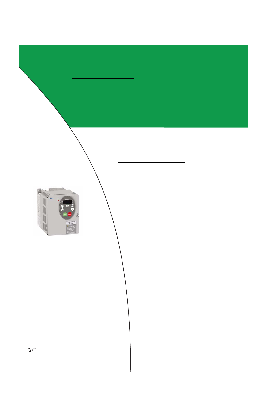
The Altivar 21 is factory-set for the most common operating conditions:
• Motor Control Mode Pt : Variable torque (Pt = 1). See page 45
• High speed UL = 50.0 Hz. See page 59
• Low speed LL = 0.0 Hz. See page 59
• Switching Frequency Level F300: depending on drive rating (see page 64
• Auto Ramp Adaptation
Parameter which depends on Macro Programming AU4 = Factory setting 0 (see page 42
• Command reference: logic inputs (CNOd = 0). See Remote Mode Start/Stop Control
• Speed reference: analog input VIA = 0–10 V or 0–20 mA (FNOd = 1, F201= 0). See Remote Mode Primary Speed Reference
Source
FMOD page 54 and Analog Input Speed Reference page 81.
• F: run forward (F111= 2).See F Logic Input Function
• R: preset speed 1 (F112= 6). See R Logic Input Function
• RES: fault reset (F113= 10). See RES Logic Input Function
• Drive ready for operation (F110= 1). See Always Active Logic Function 2
If the above values are compatible with the application, the drive can be used without changing the settings.
AU1 = Enabled (AU1 = 1). See page 64.
.
.
page 80.
.
)
):
page 54.
page 80.
page 80.
page 89.
AAV75193 09/20009 11
Page 12

Setup – Preliminary recommendations
CAUTION
INCOMPATIBLE LINE VOLTAGE
Before turning on and configuring the drive, ensure t hat the line volt age is compatib le with the supply vo ltage range s hown on the drive
nameplate. The drive may be damaged if the line voltage is not compatible.
Failure to follow these instructions can result in equipment damage.
Power switching via line contactor
CAUTION
UNINTENDED EQUIPMENT OPERATION
• Avoid operating the contactor frequently (premature ageing of the filter capacitors).
• Cycle times < 60 s may result in damage to the pre-charge resistor.
Failure to follow these instructions can result in equipment damage.
User adjustment and extension of functions
• The display unit and buttons can be used to modify the settings and to extend the functions described in the following pages.
• Return to factory settings is made easy by the Parameter Reset tYP (see page 41
).
DANGER
UNINTENDED EQUIPMENT OPERATION
• Check that changes made to the settings during operation do not present any danger.
• We recommend stopping the drive before making any changes.
Failure to follow these instructions will result in death or serious injury.
12 AAV75193 09/20009
Page 13

Setup – Preliminary recommendations
Test on a low power motor or without a motor
• In factory settings mode, Output Phase Failure Detection Mode F605 (see page 102) is active (F605 = 3). To check the drive
in a test or maintenance environment without having to switch to a motor with the same rating as the drive (particularly useful in the
case of high power drives), deactivate F605= 0.
•Set Motor Control Mode Pt = Constant V/Hz 0 (see page 45
UNINTENDED EQUIPMENT OPERATION
Motor thermal protection will not be provided by the drive if the motor current is less than 0.2 times the rated drive current. Provide an
alternative means of thermal protection.
Failure to follow these instructions can result in equipment damage.
Using motors in parallel
•Set Motor Control Mode Pt = Constant V/Hz 0 (see page 45).
)
CAUTION
CAUTION
UNINTENDED EQUIPMENT OPERATION
Motor thermal protection is no longer provided by the drive. Provide an alternative means of thermal protection on every motor.
Failure to follow these instructions can result in equipment damage.
Using in single phase supply
•Set Input Phase Failure Detection Mode F608 = Disabled 0 (see page 100).
CAUTION
UNINTENDED EQUIPMENT OPERATION
Using ATV21 in single phase supply is only allowed in training mode with motor and without load.
Failure to follow these instructions can result in equipment damage.
AAV75193 09/20009 13
Page 14

Graphic display terminal
RUN
PRG
MON
%
Hz
MODE
Loc
Rem
ENT
RUN STOP
13
1
2
3
6
7
4
5
9
10
11
14
12
8
This section describes the features of the in tegra ted graphic displa y terminal d isplay . An optiona l graphi c displ ay terminal (VW3A21101) i s
also available.
Graphic display terminal features
LED/Key Characteristics
1 Display RUN LED
2 Display PRG LED
3 Display MON LED
• Illuminates when a run command is applied to the drive.
• Flashes when there is a speed reference present with a Run command.
• Illuminates when Programming mode is active.
• Flashes in AUF,GrU modes
• Illuminates when Monitoring mode is active.
• Flashes in fault history display mode
4 Display unit 4 digits, 7 segments
5 Display unit LED
• The % LED illuminates when a displayed numeric value is a percentage.
• The Hz LED illuminates when a displayed numeric value is in hertz.
Depending on the mode, you can use the arrows to:
6 UP/DOWN keys
• Navigate between the menus
• Change a value
• Change the speed reference when the UP/DOWN LED (7) is illuminated
7 UP/DOWN LED Illuminates when the navigation arrows are controlling the speed reference
8 Loc/Rem LED Illuminates when Local mode is selected
Press to select the graphic display terminal mode.
• Run mode (default on power-up)
9MODE
• Programming mode
• Monitoring mode
Can also be used to go back to the previous menu.
10 Loc/Rem Switches between Local and Remote modes
11 ENT Press to display a parameter’s value or to save a changed value .
12 RUN LED Illuminates when the Run key is enabled
13 RUN Pressing this key when the RUN LED is illuminated starts the drive.
14 STOP
Stop/reset key.
In Local mode, pressing the STOP key causes the drive to stop based on the setting of parameter
F721.
In Remote mode, pressing the STOP key causes the drive to stop based on the setting of parameter
F603. The display will indicate a flashing “E”.
If F735 is set to 0 (default setting), pressing the stop key twice wi ll reset all resettable faults if the fault
condition has been resolved.
14 AAV75193 09/20009
Page 15

Graphic display terminal
MODE
PROG
MON
RUN
Run
mode
Programming
mode
Monitoring
mode
0.0
AUF
Fr-F
MODE MODE
Hz
ATV21 drive
Power Up
MODE
MODE Key
Fr-F
AUF
0.0
MODE
MON
MODE
MODE
C80
t0.10
n---
F60.0
25 other
parameters
PROG
RUN
MODE
Mode key
Up/Down keys
Graphic display terminal modes
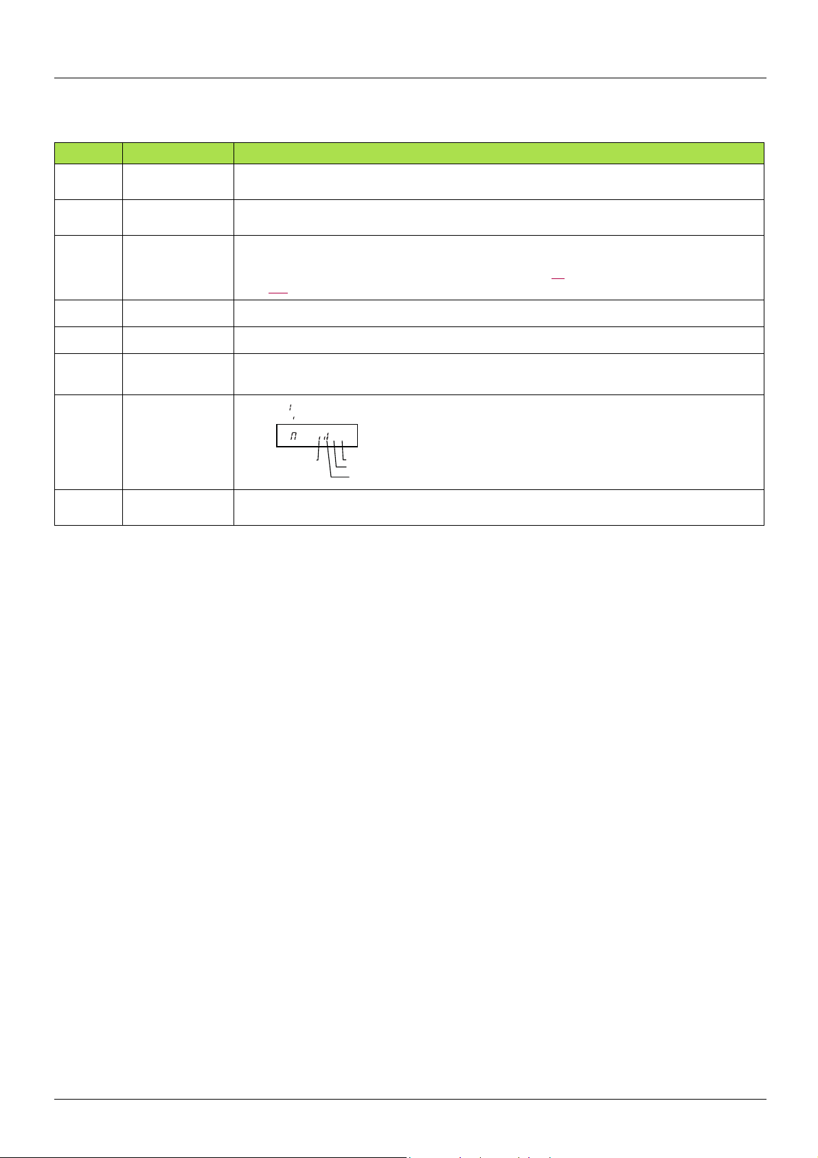
The Altivar 21 graphic display terminal has three modes of operation: Monitoring, Run and Programming.
The drive powers up in the Run mode. To select a different mode, use the MODE key as illustrated below.
Monitoring Mode
The Monitoring mode displays drive opera tional data in real time. To access the Monitoring mode, press t he MODE key u ntil the MON LED
is illuminated. Then use the UP and DOWN keys to view up to 30 different types of data.
AAV75193 09/20009 15
Page 16

Graphic display terminal
ON:
OFF:
RY-RC
FL
Monitoring Mode Displays
Display Name Description
Fr-F
F60.0
C80
Y100
P100
q60
c90
L70
h80
H75
o60.0
..11
0.1
Direction of rotation Fr-F = forward direction
Fr-r = reverse direction
Speed reference
Command frequency to drive, displayed either as Hz or in custom unit set by parameter F702
Motor current The average of the 3 phases of motor current displayed either a s amperes or as a percentage of the
drive's nameplate-rated output current. Select % or A with parameter F701.
Line voltage The average of the 3 phases of line to line input voltage s disp layed ei th er in vol ts or as a percen tag e
of the drive's rated input voltage (200 V for 208/240 V models - 400 V for 480 V models). Select % or
volts with parameter F701.
Motor voltage The average of the 3 phases of line to line out put voltages displ ayed either in volts or a s a percentage
of the drive's rated output voltage (200 V for 208/240 V models - 400 V for 480 V models). Select %
or volts with parameter F701.
Motor torque
Estimated motor torque as a percentage of the motor's rated torque
Torque current The average of the 3 phases of torque-produc ing motor current displayed either as amperes or as a
percentage of the motor's rated torque-producing current. Select % or A with parameter F701.
drive load factor The motor current as a percentage of the drive's rated output current, which may be reduced from the
drive’s nameplate current rating by adjustments in switching fr equency.
Input power
Output power
Motor operating
frequency
Logic input map
drive input power displayed in kilowatts (kW)
drive output power displayed in kilowatts (kW)
Motor operating frequency, displayed either as Hz or in custom unit set by parameter F702
ON:
OFF:
VIA
Relay output map
The bar representing VIA is displayed only if F109 = 1 or 2
F
R
RES
u101
uc01
uE01
d50
b70
h85
H75
A16.5
1500
CPU 1 version
CPU 2 version
Memory version
PID feedback
PID computed
speed reference
Accumulated input
power
consumption
Accumulated
output power
consumption
Drive rated output
current
Motor speed
Version of CPU 1
Version of CPU 2
Version of memory
Level of PID feedback, displayed either as Hz or in custom unit set by parameter F702
Speed reference command to drive as computed by the PID function, displayed eithe r as Hz or in
custom unit set by parameter F702
Accumulated input power consumed by the drive displayed in kWh
Accumulated output power supplied by the drive displayed in kWh
Drive nameplate rated output current in amperes
Motor speed in rpm
16 AAV75193 09/20009
Page 17
Graphic display terminal
ON:
OFF:
Cooling fan
Main Control board
DC Bus capacitor
Cumulative
Operation
Time
Monitoring Mode Displays (continued)
Display Name Description
N50
n50
OC3
⇔2
OH
OP3
nErr
4
N...1
Communication
counter
Displays the counter numbers of communication through the network
Normal state Displays the counter numbers of communication only at normal state in all communication through the
network
Past fault 1 The most recent fault stored in the fault history. If th e drive is in a faul t state, this is n ot the active fault .
⇔1
A fault is stored in the fault history after it is cleared by fault reset action. Press ENT to review drive
state at time of fault. See “Fault Display and History” on page 18
⇔3
⇔
Past fault 2
Past fault 3
Past fault 4
page 118
Second most recent fault.
Third most recent fault.
Fourth most recent fault.
for more detail.
Drive service alarm
and “Faults - Causes - Remedies” on
t0.10
Drive run time Cumulative drive run time. 0.01 = 1 hour.
1.00 = 100 hours
AAV75193 09/20009 17
Page 18

Graphic display terminal
ON:
OFF:
VIA
F
R
RES
ON:
OFF:
RY-RC
FL
ON:
OFF:
VIA
F
R
RES
ON:
OFF:
RY-RC
FL
Fault Display and History
When the drive faults, the graphic terminal displays a fault code. To review data about drive operation at the time of the fault, press the
MODE key to enter the Monitoring mode. Then use the Up/Down keys to scroll through the data listed in table page 16
Up to five faults can be displayed on the graphic terminal in Monitori ng mode: the present fault (if the drive is in a fault state) and the previous
four faults. To review drive operation data recorded a t the time of fault for a previous fault, press ENT when the code for the f ault is displayed.
See table below for the available information.
When a fault is reset or power is cycled to the drive, the present fault becomes Past Fault 1.
Fault History
Display Name Description
.
n2
o60.0
Fr-F
F60.0
C80
Y100
P100
..11
0.1
Fault counter Number of times in succession that this particular fault has occurred
Motor operating
frequency
Direction of
rotation
Motor operating frequency, displayed either as Hz or in custo m unit set by parameter F702
Fr-F = forward direction
Fr-r = reverse direction
Speed reference Command frequency to drive, displayed either as Hz or in custom unit set by parameter F702
Motor current
The average of the 3 phases of motor current displayed either as A or as a percentage of the drive's
nameplate-rated output current. Select % or A with parameter F701.
The average of the 3 phases of line to line input volt ages displayed either i n volts or as a perc entage of
Line voltage
the drive's rated input voltage (200 V for 208/240 V models - 400 V for 480V models). Selec t % or volts
with parameter F701.
The average of the 3 phases of line to line output voltages displa yed eith er in volts or as a percent age
Motor voltage
of the drive's rated output voltage (200 V for 208/2 40 V models - 4 00 V for 4 80 V models). Select % or
volts with parameter F701.
The bar representing VIA is dis p la y ed on l y if
F109 =1or2
Logic input map
Relay output map
t0.10
Drive run time Cumulative drive run time. 0.01 = 1 hour. 1.00 = 100 hours
I/O Map
In both the monitoring mode and th e fault history, i t is possible to view the state of t he logic inputs and the relay output s. See previous tables
on pages 16
Logic Input Map
The ON or OFF status of each logic input is displayed in bits. VIA is included in this display if parameter F109 is set to either 1 or 2.
Relay Output Map
The ON or OFF status of each relay output is displayed in bits.
18 AAV75193 09/20009
and 18.
Page 19

Graphic display terminal
Run Mode
To access the Run mode, press the MODE key until the drive operating frequency, a fault code, or a pre-alarm code is displayed.
See Faults - Causes - Remedies beginning on page 118
Changing the Display in Run Mode
Motor operating frequency is the default value displayed on the graphic terminal in Run mode. This displayed value can be changed by
setting parameter Default graphic display terminal Operational Value
The displayed value can be expressed as a percentage of the drive rating, or in amperes or volts, as appropriate for the value displayed.
The units can be changed by setting parameter Graphic display terminal (% or A/V Units)
In addition, the resolution of the speed reference and output frequenc y dis pla ys can be adju ste d by sett ing paramet ers Local Mode Speed
Reference Step Changes F707 and Graphic display terminal Frequency Resolution
Programming Mode
Use this mode to program the drive.
To access the Programming mode, use the MODE key until the PRG indicator LED on the display is illuminat ed.
for the fault and pre-alarm codes.
F710. See page 94 for a list of the display choices.
F701 (see page 94).
F708 (see pages 55 and 94).
AAV75193 09/20009 19
Page 20

Menu Structure
0.0
Mode
Mode
Mode
Fr - F AUF
MON
PRG
RUN
Hz
Sr 1...7
OLN
tHr
ub
Pt
uLu
uL
UL
LL
FH
dEC
ACC
Fr
tyP
CnoD
FnOP
FnSL
Fn
AU4
AU1
F-- -- --
GrU
ENT
Mode
a
ENT
ENT
ENT
Mode
Mode
Mode
b
c
d
AUH
Mode
ENT
a
b
c
d
Power
Up
Refer to diagram on
next page for:
Monitoring
Mode
Mode Key
ENT Key
UP/DOWN Key
To Bottom
of List
Last Five Used Parameters
Frequently Used Parameters
Changes From Factory Setting
Additional Parameters
To Top
of List
Programming
Mode
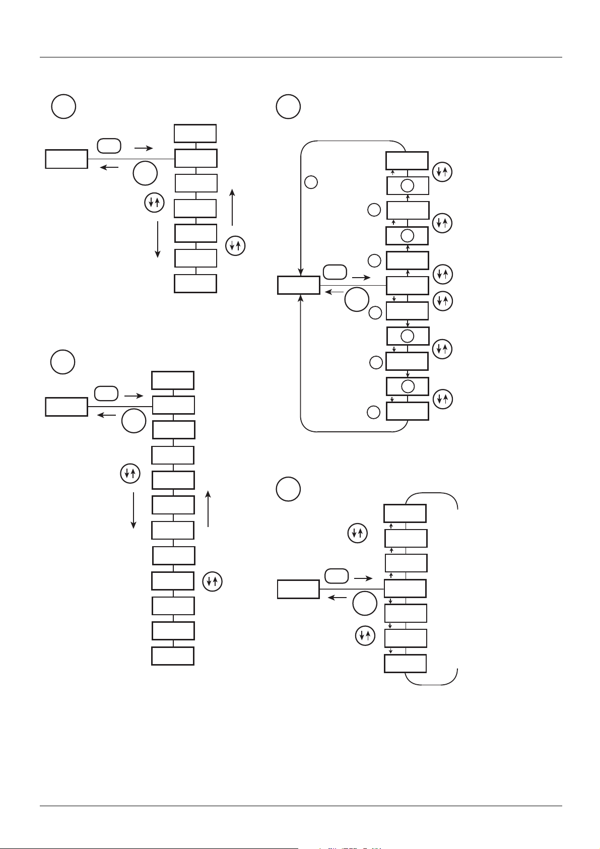
Menu Navigation
Menu navigation diagrams below and page 21 illustrate how to navigate through the programming menus and submenus.
20 AAV75193 09/20009
Page 21
Menu Structure
OLN
LL
AUH
ENT
Mode
*
*
*
*
*
a
HEAD
tHr
END
AU1
ACC
dEC
Fn
UL
LL
Pt
uLu
uL
AUF
ENT
Mode
b
c
U -- -- F
3
3
U -- -- F
U -- -- F
3
U -- -- --
U -- -- r
2
2
2
U -- -- r
3
U -- -- r
GrU
ENT
Mode
1
4
1
F911
ENT
Mode
*
*
d
F912
F102
F101
F100
F-- -- --
1. Pressing the UP key
searches the
parameter list
starting with the first
one changed.
2. Pressing the DOWN
key searches the
parameter list
starting with the last
one changed.
3. The number of
parameters
displayed within the
GrU menu
depends upon how
many have been
altered from their
factory settings.
4. When all the
changed parameters
have been displayed,
the display returns to
GrU.
History parameters
User parameters
Quick menu
Extended parameters
To Bottom
of List
To Top
of List
Menu Navigation (continued)
AAV75193 09/20009 21
Page 22
Menu Structure
Save Change
Discard
Changes
Submenus
The ATV21 drive features 4 submenus (see diagram on page 21) that are designed to reduce the time and effort required to program
application parameters. Parameters can be modified within these submenus.
AUH: History Parameters
The AUH subme nu displays, in reverse chronological order, the last 5 parameters that have been changed from their f actory settings. Each
time the AUH submenu is accessed, it searches for the latest parame ters changed fro m their factory settings. If all parameters are at their
factory settings, no display is generated.
Parameter Lock F700 is not displayed in the AUH menu, even if its value has been changed (see page 43
).
AUF: Quick Menu
The AUF submenu provides ready access to the ten basic parameters commonly used in programming the drive. In many cases,
programming the ATV21 drive is complete when these 10 parameters have been properly set (see chapter Quick Menu page 37
).
GrU: User Parameters
The GrU submenu displ ays all parameters that have been changed from their fac tory settings. Each time the GrU submenu is acce ssed,
its content is refreshed with the latest li st of parameters chan ged from the ir f actory set tings. If al l paramet ers a re at thei r fa ctor y setting , no
display is generated.
Parameters Fn and F470 – F473 are not displayed in the GrU menu, even if their values have been changed.
F– – –: Extended Parameters
The extended parameter submenu provides access to parameters used for special settings and applications.
Accessing and Changing Parameters
The diagram below illustrates how to access and change parameter values.
AUF
1
ENT
AU1
ACC
22 AAV75193 09/20009
ENT
ENT
2
10.0
3.0
Mode
Page 23

Menu Structure
Parameters that cannot be changed while the drive is running
The table below lists the parameters that cannot be changed unless the drive is stopped (displaying 0.0 or OFF on the graphic display
terminal).
Parameter Description Parameter Description
AU1 Auto ramp adaptation F316 Switching frequency control mode
AU4 Macro programming F400 Auto tuning enable
CNOd Remote mode start/stop control source F415 Motor rated full load current
FNOd Remote mode primary speed reference source F416 Motor no-load current
tYp Parameter reset F417 Motor rated speed
FH Maximum frequency F418 Frequency loop gain
uL Motor rated frequency F419 Frequency loop stability
uLu Motor rated voltage F480 Magnetizing current coefficient
Pt Motor control mode F481 Line noise compensation filter
F108 Always active logic function 1 F482 Line noise inhibitor filter
F109 VIA input function (analog or logic selection) F483 Line noise inhibitor gain
F110 Always active logic function 2 F484 Power supply adjustment gain
F111 F logic input function F485 Stall prevention control coefficient 1
F112 R logic input function F492 Stall prevention control coefficient 2
F113 RES logic input function F494 Motor adjustment coefficient
F118 VIA logic input function F495 Maximum voltage adjustment coefficient
F130 RY-RC relay primary function F496 Waveform switching adjustment coefficient
F132 FL relay function F601 Motor current limit
F137 RY-RC relay secondary function F603 External fault stop mode
F139 RY-RC relay function logic selection F605 Output phase failure detection mode
F170 Motor 2 rated frequency F608 Input phase failure detection mode
F171 Motor 2 rated voltage F613 Output sh o rt-c i rc uit detection mode
F300 Switching frequency level F626 Overvoltage fault operation level
F301 Catch on the fly F627 Undervoltage fault operation mode
F303 Auto fault reset F732
F302 Coast to stop on loss of input power F910
F305 Overvoltage fault protection F911 Permanent magnet motor step-out detection time
F307
F311 Motor rotation direction command
Supply voltage correction and motor voltage
limitation
F912
Disabling of graphic display terminal local/remote
key
Permanent magnet motor step-out detection current
level
Permanent magnet motor high-speed torque
adjustment coefficient
AAV75193 09/20009 23
Page 24

Common control schemes
Run forward
Run reverse
2-wire control
R/L1
S/L2
T/L3
FLC
FLB
FLA
RY
RC
PLC
PP
SW4
SOURCE
SINK
VIA
VIB
PA/+PO
RUN
PRG
MON
CC
PC/-
Loc
Rem
RUN STOP
FM VIA
I
U/T1
V/T2
%
Hz
MODE
ENT
W/T3
F
R
M
RES
FM
CC
P24
PLC
VV
I
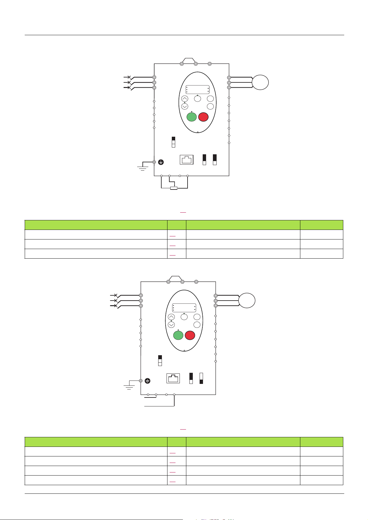
1. Wire the logic inputs as indicated in the above figure.
2. Set switch SW4 to source.
3. Program common parameters of ATV21 (see Quick Start page 37
).
4. Program specific parameters for 2-wire control as indicated in the following table:
Parameter Page Setting Factory value
CNOd (remote mode start/stop control) 54
F111 (F logic input function) 80
F112 (R logic input function) 80
0 (control terminal logic inputs) 0
2 (forward run command) 2
3 (reverse run command) 6
Note: F111 and F112 must not be switched simultaneously or the drive will go at 0 speed.
24 AAV75193 09/20009
Page 25

Common control schemes
Start forward
Start reverse
Stop
F
F
F
F
Output frequency
Line power
RES - Reverse start
F - Forward start
R - Stop
Reverse run
Forward run
3-wire control
R/L1
S/L2
T/L3
FLC
FLB
FLA
RY
RC
PLC
PP
SW4
SOURCE
SINK
VIA
VIB
PA/+PO
RUN
PRG
MON
CC
PC/-
Loc
Rem
RUN STOP
FM VIA
I
U/T1
V/T2
%
Hz
MODE
ENT
W/T3
F
R
RES
FM
CC
P24
PLC
VV
I
M
1. Wire the logic inputs as indicated in the above figure.
2. Set switch SW4 to source.
3. Program common parameters of ATV21 (see Quick Start page 37
).
4. Program specific parameters for 3-wire control as indicated in the following table:
Parameter Page Setting Factory value
CNOd (remote mode start/stop control) 54
F111 (F logic input function) 80
F112 (R logic input function) 80
F113 (RES logic input function) 80
0 (control terminal logic inputs) 0
2 (start forward - 3 wire control) 2
49 (stop input - 3 wire control) 6
3 (start reverse - 3 wire control) 10
3 wire control timing diagram:
0
ON
OF
ON
OF
ON
OF
ON
OF
AAV75193 09/20009 25
Page 26
Common control schemes
2.2 to 10 kOhm - 1/4 Watt
R/L1
S/L2
T/L3
U/T1
V/T2
W/T3
M
FLC
FLB
FLA
RY
RC
PLC
F
R
RES
FM
CC
PLC
CC
VIA
VIB
PP
PA/+PO
PC/-
I
I
SINK
SW4
SOURCE
FM VIA
RUN
PRG
MON
%
Hz
MODE
Loc
Rem
ENT
RUN STOP
P24
VV
SW3
4-20 mA Current signal
External speed control potentiometer
PA/+PO
PC/-
RES
FM
CC
P24
PLC
VV
I
U/T1
V/T2
W/T3
M
F
R
R/L1
S/L2
T/L3
FLC
FLB
FLA
RUN
PRG
MON
Loc
Rem
RUN STOP
%
Hz
MODE
ENT
RY
RC
SW4
SOURCE
PLC
FM VIA
I
SW3
CC
PP
VIA
SINK
VIB
1. Wire the analog input as indicated in the above figure.
2. Set switch SW3 to V (voltage).
3. Program common parameters of ATV21 (see Quick Start page 37
).
4. Program specific parameters for external speed control potentiometer as indicated in the following table:
Parameter Page Setting Factory value
FNOd (remote mode primary speed reference source) 54
F109 (VIA input function - analog or logic selection) 80
F200 (auto/manual speed reference switching) 83
1 (VIA) 1
0 (Analog input) 0
0 (Enabled) 0
4-20 mA speed control
1. Wire the analog input as indicated in the above figure.
2. Set switch SW3 to I (current).
3. Program common parameters of ATV21 (see Quick Start page 37
4. Program specific parameters for 4-20 mA speed control as indicated in the following table:
FNOd (remote mode primary speed reference source) 54
F109 (VIA input function - analog or logic selection) 80 0 (Analog input) 0
F200 (auto/manual speed reference switching) 83
F201 (VIA speed reference level 1) 81
26 AAV75193 09/20009
Parameter Page Setting Factory value
).
1 (VIA) 1
0 (Enabled) 0
20 % 0 %
Page 27

Common control schemes
ON
OFF
F
R
RES
ON
OFF
ON
OFF
ON
OFF
0
VIA
Output
frequency
(Hz)
Time (sec)
Preset speeds (up to seven)
R/L1
S/L2
T/L3
FLC
FLB
FLA
RY
RC
PLC
PP
SW4
SOURCE
SINK
VIA
VIB
PA/+PO
RUN
PRG
MON
CC
PC/-
Loc
Rem
RUN STOP
FM VIA
I
U/T1
V/T2
%
Hz
MODE
ENT
W/T3
F
R
RES
FM
CC
P24
PLC
VV
I
M
1. Wire the logic and analog inputs as indicated in the above figure.
2. Set switch SW4 to source.
3. Program common parameters of ATV21 (see Quick Start page 37
).
4. Program specific parameters for preset speed as indicated in the following table:
Parameter Page Setting Factory value
F109 (VIA input function - analog or logic selection) 80
F111 (F logic input function) 80
F112 (R logic input function) 80
F113 (RES logic input function) 80
F118 (VIA logic input function) 80
2 (logic input - source) 0
2 (forward run command) 2
6 (preset speed command input 1) 6
7 (preset speed command input 2) 10
8 (preset speed command input 3) 7
Example of 7-step preset speed operation:
See page 90
for additionnal information.
AAV75193 09/20009 27
Page 28

Common control schemes
R/L1
S/L2
T/L3
U/T1
V/T2
W/T3
M
FLC
FLB
FLA
RY
RC
PLC
F
R
RES
FM
CC
PLC
CC
VIA
VIB
PP
PA/+PO
PC/-
I
I
SINK
SW4
SOURCE
FM VIA
RUN
PRG
MON
%
Hz
MODE
Loc
Rem
ENT
RUN STOP
P24
VV
Forced local
Serial communication
1. For Modbus serial communication, plug the network cable into RJ45 connector on the main control board.
2. Program common parameters of ATV21 (see Quick Start page 37
).
3. Program specific parameters for serial communication as indicated in the following table:
Parameter Page Setting Factory value
CNOd (remote mode start/stop control) 54
FNOd (remote mode primary speed reference source) 54
2 (serial communication) 0
4 (serial communication) 1
Forced local
PA/+PO
PC/-
RES
FM
CC
P24
PLC
VV
I
U/T1
V/T2
W/T3
M
F
R
R/L1
S/L2
T/L3
FLC
FLB
FLA
RY
RC
SW4
SOURCE
RUN
PRG
MON
Loc
Rem
RUN STOP
%
Hz
MODE
ENT
PLC
SINK
PP
VIA
VIB
1. Wire the logic input as indicated in the above figure.
2. Set switch SW4 to source.
3. Program common parameters of ATV21 (see Quick Start page 37
4. Program specific parameter for forced local as indicated in the following table:
F113 (RES logic input function) 80
Parameter Page Setting Factory value
28 AAV75193 09/20009
FM VIA
I
CC
).
48 (forced local) 10
Page 29
Common control schemes
Feedback
transmitter
Feedback mA or voltage signal
Setpoint 0 - 10 V
PID control
R/L1
S/L2
T/L3
FLC
FLB
FLA
RY
RC
PLC
PP
SW4
SOURCE
SINK
VIB
CC
PA/+PO
RUN
PRG
MON
RUN STOP
VIA
PC/-
Loc
MODE
Rem
ENT
FM VIA
I
%
Hz
SW3
RES
FM
CC
P24
PLC
VV
I
U/T1
V/T2
W/T3
F
R
M
P
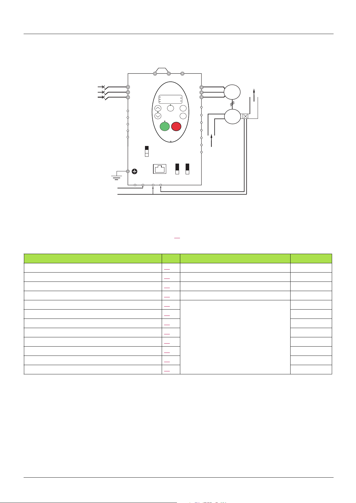
1. Wire analog inputs as indicated in the above figure.
2. Set switch SW4 to source.
3. If the feedback is a milliamp signal, set switch SW3 t o the I (current ) posit ion. If the fee dback is a volt age sig nal, set switc h SW3 to the
V (voltage) position.
4. Program common parameters of ATV21 (see Quick Start page 37
).
5. Program specific parameters for PID control as indicated in the following table:
Parameter Page Setting Factory value
FNOd (remote mode primary speed reference source) 54
F109 (VIA input function - analog or logic selection) 80
F200 (auto/manual speed reference switching) 83
F360 (PID control enable) 86
F359 (PID control waiting time) 87
F362 (PID proportionnal gain) 86
F363 (PID integral gain) 86
F366 (PID derivative gain) 87
F380 (PI regulator reversal direction correction) 87
2 (VIB) 1
0 (Analog input) 0
0 (Enabled) 0
1 (Enabled - feedback source is VIA) 0
In accordance with the application
0 s
0.30 %
0.20
0.00
0
F391 (Stop on LL hysteresis) 87 0.2 Hz
F392 (PI wake up threshold on PI error) 87
F393 (PI wake up threshold on PI feedback error) 87
0.0 Hz
0.0 Hz
AAV75193 09/20009 29
Page 30

Drive Operation
Local and Remote Modes of Operation
Overview
The ATV21 drive has two modes of operation, local and remote.
In local mode, the ATV21 drive can be operated only from the graphic display terminal:
• Use the RUN and STOP keys for command control
• Use the UP and DOWN keys for speed control
In remote mode, the ATV21 drive is operated from a combination of the command and speed reference sources defined by programming
parameters Remote Mode Primary Speed Reference Source
Command Sources
The command source (CNOd) choices are:
FNOd and Remote Mode Start/Stop Control CNOd (see page 54).
• External signals to the control terminal logic inputs F, R, RES and VIA
• Serial communication control (Modbus
• Graphic display terminal RUN and STOP keys
®
, Metasys® N2, Apogee® FLN, BACnet, or LonWorks®)
Speed Reference Sources
The speed reference source (FNOd) choices are:
• External signals to the control terminal analog inputs VIA or VIB
• (4–20 mA, 0–10 Vdc),
• External signals to the control terminal logic inputs assigned to
• +/- Speed
• Serial communication control (Modbus
• graphic display terminal UP and DOWN keys
Changes to parameters FNOd and CNOd can only be made when the drive is stopped.
®
, Metasys® N2, Apogee® FLN, BACnet, or LonWorks®)
30 AAV75193 09/20009
Page 31

Drive Operation
LOC
REM
VIA
VIB
VIA
VIB
Serial communication
Run/forward
Run/reverse
Logic input
function = 48
Graphic display
terminal
local/remote key
Speed reference
Graphic display terminal
Logic inputs
Commands
CNOd
Serial communication
+/- Speed
References
FNOd
graphic
display
terminal
Logic input function = 38
or
Parameter F200 = 1
Serial communication
Graphic
display
terminal
Graphic
display
terminal
Graphic
display
terminal
Serial communication
+/- Speed
Serial
communication
F207
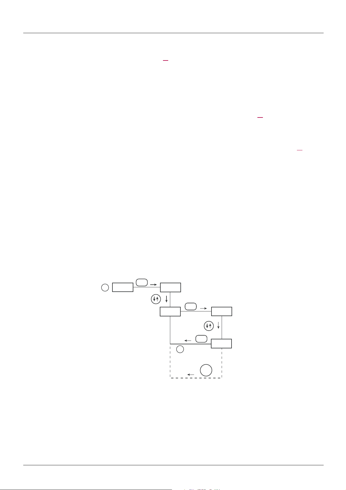
Command Mode Selection and Priorities
The diagram below illustrates the control inputs and selection logic which determine the source of the drive's start/stop and speed reference
commands.
Command and Reference Switching
Parameters CNOd and FNOd are the first layers of logic used by the drive to determine its command (CNOd) and speed reference
(FNOd) source.
Remote Mode Secondary Speed Reference Source F207 is a secondary speed reference source that may override th e source selected
by FNOd (see page 56
).
The speed reference source identified by F207 takes cont rol if either:
• A logic input assigned to function 38 (frequency reference source switching) is enabled, or
• Parameter Auto/Manual Speed Reference Switching F200 is set to 1 and the drive's outp ut frequency is equal to or less than 1Hz
(see page 83
If a serial communication link is established, it can take control of the ATV21 drive, overriding inputs identified by CNOd, FNOd, and
F207. Control is restored to CNOd, FNOd, and F207 only if:
• The serial communication link relinquishes control, or
• A logic input assigned to function 48 (forced local) is enabled.
The final layer of logic used by the drive to determine its command source is the LOC/REM key on the graphic display terminal.
When the drive is set to local mode (by pressing the LOC/REM key, lighting the local mode LED), the drive responds only to commands
from the graphic display terminal.
AAV75193 09/20009 31
).
Page 32

Drive Operation
Remote mode
Local mode
ON
OFF
LOC
REM
Key
Output Frequency
Local Run Commande
Remote Run Commande
Run Status
ON
OFF
The remote run command and
frequency command are transferred
to the local mode when the
LOC/REM key is pressed.
In this example, the run command
and frequency command from
the remote mode are copied to
the local mode, and the motor
continues to run.
Remote mode
Local mode
ON
OFF
LOC
REM
Key
Output Frequency
Local Run Commande
Remote Run Commande
Run Status
ON
OFF
When switching from the local
mode to the remote mode, the run
command and frequency
command are determ ined by
the setting in the remote mode.
In this example, when the
LOC/REM button is pressed, the
motor in started.
This is due to the application of a
remote run command when
the drive exits the local mode and
enters the remote mode.
Set frequency
at remote mode
Selecting Local or Remote Mode
DANGER
UNINTENDED EQUIPMENT OPERATION
• Know the state of the frequency and run commands from the remote source before exitin g the local mode.
• Uponentering the remote mode, the drive will respond to the most recent command from the remote source, even if it was
received before entering or while in the local mode.
Failure to follow these instructions will result in death or serious injury
Switching between local and remote mode is achieved with the LOC/REM key in the drive’s graphic display terminal.
The LOC/REM key can be disabled by setting parameter Disabling of graphic display terminal Local/Remote Key F732 to 1
(see page 58
).
When parameter Bumpless Transfer From Remote To Local Control
operation is achieved when switching from remote to local mode (see page 55
For example, if the bumpless transfert feature is active and if the motor is running at f ull speed with the drive in remote mode, the motor will
still run at full speed after the drive is transferred to local mode.
Conversely, when switching from local to remote mode, t he run and spe ed command is not tran sfer red to t he remote mode. Upon ent ering
the remote mode, the drive will operate on the run and speed command set by the remote source even if it was re ceived before en tering or
while in the local mode.
The diagram below is an ex a m p le timing diagram.
F295 is set to 1 (factory setting), a bumpless tranfer of motor
).
Switching Between Local and Remote Mode
32 AAV75193 09/20009
Page 33

Drive Operation
Local Mode
When the ATV21 drive is in local mode, the LED above the LOC/REM key is illuminated.
Starting and Stopping the Motor in Local Mode
Start and stop the motor with the RUN and STOP keys on the graphic display terminal.
The setting of parameter Local Mode Motor Stop Type
(see page 55
•If F721 is set to 0 (factory setting), the motor will stop on a ramp, based on the time value set in parameter
•If F721 is set to 1, power will be removed from the motor whe n the STOP key is pressed, al lowing the motor to coast to a stop with
Use of the RUN and STOP keys in local mode can be disabled usi ng parameter Disabling of graph ic display termi nal RUN and STOP Keys
in Local Mode F733(see page 58
):
dEC (deceleration time 1) or parameter F501 (deceleration time 2).
the ramp-down time determined by inertia and friction.
).
F721 determines how the motor stops when the drive is in local mode
Adjusting Motor Speed in Local Mode
Set the motor speed using the UP and DOWN keys on the graphic display terminal. Motor speed can be adjusted while the drive is
operating.
Normally, motor frequency changes by 0.1 Hz each time the UP or DOWN key is pressed. This rate of speed change can be altered by
entering a new frequency step change into parameter Local Mode Speed Referen c e Step Changes
If the ENT key is pressed after the motor s peed ha s b een adj usted, tha t spee d setp oin t value wi l l be ent ered in to parame te r FC. The next
time the drive is started in the local mode, it will accelerate the motor directly to the speed setpoint memorized by Local Mode Speed
Reference FC (see page 54
).
F707 (see page 55).
Selecting Motor Rotation Direction in Local Mode
Motor rotation direction is set by parameter Local Mode Motor Rotation Direction Command Fr (see page 54). The four selections are:
• 0: Forward only (factory setting)
• 1: Reverse only
• 2: Forward, with reverse selectable from the graphic display terminal (1)
• 3: Reverse, with forward selectable from the graphic display terminal (1)
(1)If Fr is set to eith er 2 or 3, motor ro tation ca n be set t o forward by pressin g the UP ke y while holdi ng the ENT ke y. Reverse can be set
by pressing the DOWN key while holding the ENT key.
Motor rotation is indicated on the graphic display terminal as Fr-F for forward and as Fr-r for reverse.
The ability to run in the Forward or Reve rse direction can be set with p arameter Moto r Rotation Direction Command
F311 (see page 57).
Resetting drive Faults in Local Mode
It is not possible to clear a drive fault if the cause of the fault persists. Be sure to diagnose an d rectify the cause of the f ault before attempting
a drive reset.
With the STOP Key
To clear a drive fault in local mode:
1. Press the STOP key. See Automatically Resettable Faults on page 97
possible to reset the drive, the graphic display terminal will display CLr.
2. To clear the fault, press the STOP key a second time.
3. If the cause of the fault is still present, the CLr display will not appear. Dia gnose and solve the proble m before attempting to rese t the
drive.
Use of the STOP key as a fault reset can be set with parameter Disabling of graphic display terminal Fault Reset Function
(see page 58
In the event of an OL1 or OL2 fault, the following time periods must pass before a fault reset is possible:
• OL1 (drive overload)—about 30 seconds after the occurrence of the fault
• OL2 (motor overload)—about 120 seconds after the occurrence of
the fault
).
By Cycling Line Power
A drive fault can also be reset by removin g and restoring line p ower. Ensure that the cause of the fault is no longer present and leave power
removed long enough for all of the LEDs on the face of the drive to extinguish.
Cycling power to clear a fault can cause the fault history to be lost. Refer t o parameter F602 on page 100
for a list of faults that can be reset with the STOP key. If it is
F735
for Drive Fault Memory options.
AAV75193 09/20009 33
Page 34

Drive Operation
Logic Input Functions Active in Local Mode
The logic input functions listed in the table below are active, even if CNOd is set to 1 (graphic display terminal control). See table on
page 67
for logic input function settings.
Logic Input
Function No.
1
54
10
55
11
45
16 Combination of run permissive and fault reset
38 Frequency reference source switching
41
42
43
44
46
47
51 Clear accumulated power consumption display
52 Fire-mode drive operation
53 Forced-mode drive operation
62 Holding of RY-RC relay output
64 Cancellation of last graphic display terminal command
Description
Run permissive
Fault reset
External Fault
+/- Speed
External overheating fault input
Remote Mode
When the ATV21 drive is in the remote mode, the LOC/REM LED is off.
Starting and Stopping the Motor in Remote Mode
The diagram on page 31 illustrates the start/stop command source when the drive is in remote mode.
With Logic Input Terminals
Use the logic input terminals F, R, RES, or VIA to start the drive if:
• Parameter CNOd is set to 0 (factory setting), and
• Serial communication control has not been established.
With the graphic display terminal
The drive responds to commands from the graphic display terminal, just as in local mode, if:
• Parameter CNOd is set to 1, and
• Serial communication control has not been established.
With Serial Communication
The drive responds to commands sent over the serial c ommunication l ink (Modbus®, Metasys® N2, Apogee® FLN, BACnet or LonWorks®)
if parameter CNOd is set to 2.
With the graphic display terminal STOP Key
The graphic display terminal STOP key is active when the drive is in remote mode. Pressing the STOP key causes the drive to stop
according to the setting of parameters F603, F604, and F251 (see page 93
graphic display terminal displays E and the fault rela y is activated.
and page 66) . After the drive has come to a stop, the
34 AAV75193 09/20009
Page 35

Drive Operation
Adjusting the Motor Speed in Remote Mode
The diagram on page 31 illustrates the speed reference source when the drive is in remote mode.
By Analog Input VIA
A 0–10 Vdc or 4–20 mA signal connected to VIA and CC can be used to adjust the motor speed if:
• Parameter FNOd is set to 1 (factory setting).
• Alternate speed reference source parameter Remote Mode Secondary Speed Reference Source F207 has not been enabled
(see page 56
• Serial communication control has not been established.
The analog signal type depends on the setting of switch SW3 and parameters F109, F201–F204, and F470–F471.
By Analog Input VIB
A 0–10 Vdc signal connected to VIB and CC can be used to adjust the motor spe ed if:
• Parameter FNOd is set to 2.
• Alternate speed reference source parameter F207 has not been enabled.
• Serial communication control has not been established.
The control that VIB has over motor speed depends on the setting of parameters F210–F213, F472–F473, and F645.
By graphic display terminal Control
graphic display terminal control of the motor speed is enabled, if:
• Parameter FNOd is set to 3.
• Alternate speed reference source parameter F207 has not been enabled.
• Serial communication control has not been established.
).
By Serial Communication Control
Serial communication control (Modbus, Metasys N2, Apogee FLN, BACnet or LonWorks) of the motor speed is enabled, if:
• Parameter FNOd is set to 4.
• Alternate speed reference source parameter F207 has not been enabled.
By +/- Motor Speed Control
+/- Motor speed control is enabled, if:
• Parameter FNOd is set to 5.
• Alternate speed reference source parameter F207 has not been enabled.
• Serial communication control has not been established.
Selecting Motor Rotation Direction in Remote Mode
The diagram on page 31 illustrates the motor rotation command source when the drive is in remote mode.
With Logic Input Terminals
Use the logic input terminals F, R, RES, or VIA to select motor rotation direction if:
• Parameter CNOd is set to 0 (factory setting).
• Serial communication control has not been established .
With the graphic display terminal
Motor rotation direction can be set by pressing the graphic display terminal UP and ENT keys if:
• Parameter CNOd is set to 1.
• Serial communication control has not been established.
• Parameter Fr is set to either 2 or 3.
With Serial Communication
The drive responds to commands sent over the serial communication link (Modbus, Metasys N2, Apogee FLN, BACnet or LonWorks) if
Parameter CNOd is set to 2.
AAV75193 09/20009 35
Page 36

Drive Operation
Resetting drive Faults in Remote Mode
The diagram on page 31 illustrates the fault reset command source when the drive is in remote mode.
It is not possible to clear a drive fault if the cause of the fault persists. Be sure to diagnose an d rectify the cause of the f ault before attempting
to reset the drive.
See Automatically Resettable Faults on page 97
With the Logic Input Terminals
Use the logic input terminals F, R, RES, or VIA to reset a drive fault if:
• Parameter CNOd is set to 0 (factory setting), and
• Serial communication control has not been established.
With the graphic display terminal
The STOP key can be used to clear a drive fault if:
• Parameter CNOd is set to 1, and
• Serial communication control has not been established.
To clear a drive fault in graphic display terminal mode, press the STOP key. If it is possible to reset the drive, the graphic display terminal
will display CLr. To clear the fault, press the STOP key a second time.
If the cause of the fault is still present, the CLr display will not appear. Diagnose and solve the problem before attempting to reset the drive.
for a list of faults that can be reset in remote mode.
The use of the STOP key as a fault reset can be disabled by setting parameter F735 to 1.
With Serial Communication
A drive fault can be reset over the serial communication link (Modbus, Metasys N2, Apogee FLN, BACnet or LonWorks) if parameter
CNOd is set to 2.
In the event of an OL1 or OL2 fault, the following time periods must pass before a fault reset is possible:
• OL1 (drive overload) - about 30 seconds after the occurrence of the fault.
• OL2 (motor overload) - about 120 seconds after the occurrence of the fault.
By Cycling Line Power
A drive fault can also be reset by removin g and restoring line p ower. Ensure that the cause of the fault is no longer present and leave power
removed long enough for all of the LEDs on the face of the drive to go out.
Cycling power to clear a fault can cause the fault history to be lost. Refer to parameter F602 on page 100
for drive fault memory options.
36 AAV75193 09/20009
Page 37

Quick Start
0
Output frequency (Hz)
Time (Sec)
Quick menu AUF
The AUF submenu provides ready access to the ten basic parameters commonly used in programming the drive.
In many cases, programming the ATV21 drive is complete when these 10 parameters and motor parameters have been properly set.
Code Name/Description Adjustment range Factory setting
AU1
ACC
M Auto Ramp Adaptation
0
1
2
v Disabled
v Enabled - Acceleration Time 1
v Enabled (ACC only)
If parameter AU1 is set to 1 or 2, the drive will monitor its own loading level and optimize the acceleration and
deceleration ramps. The acceleration and deceleration (AU1 = 1 only) rates will be automatically adjusted
between 1/8 to 8 times the settings of ACC and dEC, depend ing on the drive’s current rating and th e load level
on the motor. ACC and dEC should be appropriately set for an average load in the application. If the load on
the motor increases rapidly during ramp up or ramp down, the auto ramp adaptation feature may not prevent the
drive from experiencing an overcurrent or overvoltage fault.
If the application requires a consistent accelerat ion and deceleration time, set AU1 to 0, and set ACC and dEC
manually as needed. The manual acceleration a nd deceleration times can still be overridden by the Motor Current
Limit F601 (see page 47
Operation LevelF626 (see page 101
M Acceleration Time 1
The setting of parameter ACC determines the slope of the acceleration ramp an d the ti me it takes f or the out put
frequency of the drive to increase from 0 Hz to the setting of Maximum Frequency FH (see page 59
If parameter Auto Ramp Adaptation AU1 (see page 64
or decreased from the setting of ACC, depending on the amount of load on the motor during ramp up.
- 1
ACC and Deceleration Time 1 dEC (see page 60)
) and Overvoltage Fault Protection F305 (see page 101) and Overvoltage Fault
) functions.
0.0 to3200 seconds According to drive
model
(see table page 128
).
) is set to 1 or 2, the acceleration ramp may be incre ased
).
dEC
If two different acceleration rates are needed, see parameter Acceleration Time 2
M Deceleration Time 1
The setting of parameter dEC determines the slope o f the dece leration ra mp and t he time it takes f or the o utput
frequency of the drive to decrease from the setting of Maximum Frequency FH to 0 Hz.
If parameter Auto Ramp Adaptation AU1 is set to 1 or 2, the d ecelerat ion ramp may be in creased or decrea sed
from the setting of dEC, depending on the amount of load on the motor during ramp down. See diagram above.
If two different deceleration rates are needed, see parameter Deceleration Time 2
0.0 to3200 seconds According to drive
F500 on page 61.
model
(see table page 128
F501 on page 61.
).
AAV75193 09/20009 37
Page 38

Quick Start
Code Name/Description Adjustment range Factory setting
LL
UL
tHr
M Low Speed
Parameter LL sets the minimum frequency that can be commanded to the drive by the local or remote speed
reference source.
See diagram above.
M High Speed
Parameter UL sets the maximum frequency that can be commanded to the drive by the local or remote speed
reference source.
The top end of its range is limited by the setting of Maximum frequency FH. See diagram above.
M Motor Rated Current Overload Setting
Set parameter tHr to the motor’s rated current as indicated on the motor nameplate for the selected operating
voltage.
If parameter % or A/V Units F701 is set to 1 (see page 94), parameter tHrwill be adjusted in amperes.
If parameter % or A/V Units F701 is set to 0, para meter tHr will be adjusted i n percentage. In this case, d ivide
the motor rated current by the drive rated current (as listed on its nameplate) and set parameter tHr to the
resulting percentage.
The setting of parameter Switching Frequency Level
sake of this calculation (see page 64
).
F300 does not change the drive’s rated current for the
0.0 toUL Hz 0.0 Hz
0.5 toFH Hz 50.0 Hz
10 to 100% of the
drive’s output current
rating
100 %
FM
M Analog Output Scaling
Parameter FN is used to match the FN terminal output signal with the input requirements of the attached panel
meter by adjusting the slope and bias of the analog output signal. Before adjusting FN, set FNSL to either 15
or 17. As you adjust the value of FN, monitor the display on the attached panel meter. When the meter display
reaches 100%, press the ENT key on the drive graphic display te rminal. The drive will fla sh between FN and the
adjusted value, indicating that the adjustment has bee n s aved.
-
38 AAV75193 09/20009
Page 39

Quick Start
0
Motor Rated Voltage
Motor Voltage Boost
Motor Rated Frequency
Output Frequency (Hz)
Output Voltage (%)
0
Motor Rated Voltage
Motor Voltage Boost
Motor Rated Frequency
Output Frequency (Hz)
Output Voltage (%)
Code Name/Description Factory setting
Pt
M Motor Control Mode
0
1
v Constant V/Hz
Use constant V/Hz mode for loads that require the same torque at low speeds as at rated speeds. Low speed
torque can be adjusted manually by setting parameter Motor Voltage Boost ub (see page 47
v Variable torque
Use variable torque mode for loads such as centrifugal fans and pumps whose torque requirements increase as
a square of the increase in motor speed. Low speed t orque can be adj usted manual ly by setti ng parameter Motor
Voltage Boost ub (see page 47
1
).
).
2
3
4
5
6
(1) See page 44 fo r more details.
v Constant V/Hz with automatic torque boost (1)
See the diagram on page 44
.
This mode is similar to the constant V/Hz mode (for loads that require the same torque at l ow speeds as at rated
speeds), except it automatically increases motor voltage and torque to compensate for increases in load.
v Sensorless vector control (1)
Use sensorless vector control mode to increase torque at motor speeds below 3 Hz or to improv e speed regulation
(0.5 to 1%).
v Energy saving
In energy savings mode, the ATV21 drive monitors motor loading and aut omatically modulates the voltage appl ied
to the motor to optimize energy consumption.
If the ATV21 drive and the connected motor have the same po wer rating, and if the motor has a nominal 1800 rpm
rating, no motor auto-tuning is required to use this motor control mode. Otherwise, follow the steps outlined in
“Motor Tuning” on page 48
.
v Reserved (DO NOT USE)
v Reserved (DO NOT USE)
AAV75193 09/20009 39
Page 40

Quick Start
Code Name/Description Adjustment range Factory setting
uL
uLu
M Motor Rated Frequency
Set parameter uL to the motor’s rated frequency as indicated on the motor nameplate.
It is possible to set the drive’s various motor control frequencies to 50 Hz by setting Parameter Reset tYP
to 1, the 50 Hz reset. For more information, see page 41
M Motor Rated Voltage
Set parameter uLu to the motor’s rated voltage as ind icated on the motor nameplate.
pppM3X: 50 to 330 V.
ATV21
pppN4: 50 to 660 V
ATV21
Drive output voltage cannot be set to exceed the input line voltage level.
25.0 to 200.0 Hz 50.0 Hz
.
According to drive
rating
According to drive
rating
Motor parameters
Configure the motor parameters and perform an auto-tuning (Auto Tuning Enable F400 = 2, see page 49 for auto-tuning).
Code Name/Description Adjustment range Factory setting
F415
M Motor Rated Full Load Current
Set parameter F415 to the motor rated full load current in amperes as indicated on the motor’s nameplate.
0.1 to 200.0 A According to drive
model (1)
F417
Code Name/Description Adjustment range Factory setting
F400
(1) See table page 128
(2)Parameter Auto Tuning Enable F400 is reset to “0” after the auto tuning is performed.
M Motor Rated Speed
Set parameter F417 to the motor rated speed in rpm as indicated on the motor’s nameplate.
M Auto Tuning Enable
0
1
2
v Disabled
v Enabled (2): parameter Auto Torque Boost
v Enabled (2): complete auto tuning
F402 may need adjustment
100 to 15,000 rpm According to drive
model (1)
- 0
40 AAV75193 09/20009
Page 41

Programming Parameters
Parameter Reset (tYP)
Parameter Reset Options
The ATV21 drive offers three options to return parameters to their factory default settings:
• Factory reset: set parameter tYP to 3
• 50 Hz reset: set parameter tYP to 1
• 60 Hz reset: set parameter tYP to 2
Code Name/Description Factory setting
tYP
M Parameter Reset
0
1
2
3
4
5
6
7
8
9
-
v 50 Hz Parameter Reset
Setting parameter tYP to a value of 1 will set specific parameters to values suit able for many 50 Hz (motor base
frequency) applications.
See Parameters whose values after a reset vary by reset type table on page 128
of parameters that are affected by this reset action and their resultant values.
v 60 Hz Parameter Reset
Setting parameter tYP to 2 sets specific parameters to values suitable for many 60 Hz (motor base frequency)
applications. See table "Parameters whose values after a reset vary by reset type" on page 128
"Parameters whose values after a reset are drive model depend ant but DO NOT vary by reset type" on page 129
for a list of parameters that are affected by this reset acti on and their resultant values.
v Factory Reset
Setting parameter tYP to 3 resets most parameters to their factory sett ings. See tables o n pages 123
a listing of the values that will be copied into the drive by this factory reset action:
- Parameters whose values after a reset DO NOT vary by reset type (on page 123
- Parameters whose values after a reset vary by reset type (on page 128
- Parameters whose values after a reset are drive model dependant but DO NOT vary reset type (on page 129
- Parameters whose values after a reset are drive model and reset type dependant (on page 130
- Parameters whose values do not change if a reset is performed (on page 131
A factory reset will also clear the fault history.
v Fault History Reset
Setting parameter tYP to 4 resets the fault history. As soon as the fault history is reset, parameter tYP
resumes its default value of 0.
v Elapsed Motor Run Time Reset
Setting parameter tYP to 5 resets the elapsed motor run time clock. As soon as the ela psed motor run time clock
is reset, parameter tYP resumes its default value of 0.
v Reset of EtYP Fault
Setting parameter tYP to 6 resets a EtYP fault. As soon as the EtYP fault is reset, parameter tYP
resumes its default value of 0.
v Save User-defined Settings
The drive parameter settings can be stored into memory into the drive as a custom parameter set.
Set parameter tYP to 7 to save the current drive parameter settings to memory
v Recall User-defined Settings
The drive parameter settings can be reloaded into the drive as a custom parameter set.
Set parameter tYP to 8 to reload into the drive the parameter settings last saved by setting tYP to 7
v Elapsed Drive Run Time Reset
Setting parameter tYP to 9 resets the elapsed drive run time clock. As soon as the elapsed motor run time clo ck
is reset, parameter tYP resumes its default value of 0.
0
and table on page 130 for a list
and table
to 131 for
).
).
).
).
).
AAV75193 09/20009 41
Page 42

Programming Parameters
Macro Programming (AU4)
The ATV21 drive can be configured for four common control schemes by setting parameter AU4:
Code Name/Description Factory setting
AU4
M Macro Programming (1)
0
1
2
v Factory setting
- Command reference: logic inputs (CNOd = 0). See Remote Mode Start/Stop Control
- Speed reference: analog input VIA = 0–10 V or 0–20 mA (FNOd = 1, F201= 0). See Remote Mode
Primary Speed Reference Source
- F: run forward (F111= 2).See F Logic Input Function
- R: preset speed 1 (F112= 6). See R Logic Input Function
- RES: fault reset (F113= 10). See RES Logic Input Function
- Drive ready for operation (F110= 1). See Always Active Logic Function 2
v Run permissive
- Command reference: logic inputs (CNOd = 0). See Remote Mode Start/Stop Control
- Speed reference: analog input VIA = 0–10 V or 0–20 mA (FNOd = 1). See Remote Mode Primary Speed
Reference Source
- F: run forward (F111= 2).See F Logic Input Function
- R: run permissive (F112= 1). See R Logic Input Function
- RES: fault reset (F113= 10). See RES Logic Input Function
v 3-wire control:
- Command reference: logic inputs (CNOd = 0). See Remote Mode Start/Stop Control
- Speed reference: analog input VIA = 0–10 V or 0–20 mA (FNOd = 1). See Remote Mode Primary Speed
Reference Source
- F: run forward (F111= 2).See F Logic Input Function
- R: stop ramp (F112= 49). See R Logic Input Function
- RES: fault reset (F113= 10). See RES Logic Input Function
0
page 54.
FMOd page 54 and Analog Input Speed Reference page 81.
page 80.
page 80.
page 80.
page 89.
page 54.
page 54.
page 80.
page 80.
page 80.
page 54.
page 54.
page 80.
page 80.
page 80.
3
4
(1) W hen programming parameter AU4, the graphic display terminal will display two numbers. The left number is the value last entered
into AU4. The right number will always be 0. Use the UP/DOWN keys to change the right number to the desired value and press ENT.
Entering 0 into AU4 has no effect on the drive. Programming 0 into AU4 will not return the seven parameters to their factory default
values.
v +/- Speed:
- Command reference: logic inputs (CNOd = 0). See Remote Mode Start/Stop Control
- Speed reference: +/- Speed (FNOd = 5). See Remote Mode Primary Speed Reference Source
- F: run forward (F111= 2).See F Logic Input Function
- R: + Speed (F112= 41). See R Logic Input Function
- RES: - Speed (F113= 42). See RES Logic Input Function
v 4-20 mA speed reference:
- Command reference: logic inputs (CNOd = 0). See Remote Mode Start/Stop Control
- Speed reference: analog input VIA = 4–20 mA (FNOd = 1, F201= 20). See Remote Mode Primary Speed
Reference Source
- F: run forward (F111= 2).See F Logic Input Function
- R: preset speed 1 (F112= 6). See R Logic Input Function
- RES: fault reset (F113= 10). See RES Logic Input Function
page 54 and Analog Input Speed Reference page 81.
page 80.
page 80.
page 80.
page 80.
page 80.
page 80.
page 54.
page 54.
page 54.
42 AAV75193 09/20009
Page 43

Programming Parameters
Parameter Lock (F700)
Code Name/Description Factory setting
F700
M Parameter Lock
0
1
All parameters are unlocked and can be changed.
See table on page 23
Only parameter F700 can be changed.
for the parameters that cannot be changed while the drive is running.
0
Display of Submenu AUF (F738)
Code Name/Description Factory setting
F738
M Display of Submenu AUF
The setting of this parameter det erm i n es whether the AUF submenu, Quick Menu, will be displayed on the
graphic terminal (see page 22
0
1
AUF displayed.
AUF not displayed.
).
0
AAV75193 09/20009 43
Page 44

Motor Control Parameters
Motor Rated Voltage
Motor Rated Frequency
: Automatically
adjusts the
amount of
torque boost.
Output Voltage (%)
Output Frequency (Hz)
Motor Control Mode (Pt)
Constant V/Hz Mode with AutomaticTorque Boost (Pt= 2)
Use parameter Auto Torque Boost F402 to adjust the amount of automatic torque boost (see page 53).
If the ATV21 drive and the connected motor have the same power rating, and if the motor has a nominal 1800 rpm rating, no motor
auto-tuning is required to use this motor control mode. Otherwise, follow the steps outlined in “Motor Tuning” on page 48
Due to the feedback circuit used in this mode, it is possible for motor speed to oscillate. If this occurs, select the Constant V/Hz mode
(Pt = 0) and adjust torque boost manually with parameter ub.
0
.
Sensorless Vector Control Mode (Pt= 3)
If the ATV21 drive and the connected motor have the same power rating, and if the motor has a nominal 1800 rpm rating, no motor
auto-tuning is required to use this motor control mode. Otherwise, follow the steps outlined in “Motor Tuning” on page 48
Sensorless vector control mode is only for use in applications where:
- Each motor is powered by its own ATV21 drive (not for multi-motor applications).
- The motor has a power rating equal to that of the ATV21 drive, or no lower than one hp rating less.
- The motor has between two and eight poles (900 to 3600 rpm).
Sensorless vector control will not improve motor control above the motor’s rated speed.
Sensorless vector control is most effective if the motor leads are less than 30 m (100 ft) in length. If motor leads longer than 30 m (100 ft)
are required, perform an auto-tuning with the long motor leads included in the circuit. Motor torque may not be maximized at the motor’s
rated frequency due to voltage drop in the motor leads.
Connecting a load reactor or a motor protecting filter on the output of the ATV21 drive may reduce the torque generated by the motor in
sensorless vector control mode. Auto-tuning will most likely not be possible with a reactor or filter attached to the drive. Manual tuning will
be required.
.
44 AAV75193 09/20009
Page 45

Motor Control Parameters
0
Motor Rated Voltage
Motor Voltage Boost
Motor Rated Frequency
Output Frequency (Hz)
Output Voltage (%)
0
Motor Rated Voltage
Motor Voltage Boost
Motor Rated Frequency
Output Frequency (Hz)
Output Voltage (%)
Code Name/Description Factory setting
Pt
M Motor Control Mode
0
1
v Constant V/Hz
Use constant V/Hz mode for loads that require the same torque at low speeds as at rated speeds. Low speed
torque can be adjusted manually by setting parameter Motor Voltage Boost ub (see page 47
v Variable torque
Use variable torque mode for loads such as centrifugal fans and pumps whose torque requirements increase as
a square of the increase in motor speed. Low speed t orque can be adj usted manual ly by setti ng parameter Motor
Voltage Boost ub (see page 47
1
).
).
2
v Constant V/Hz with automatic torque boost
See the diagram on page 44
.
This mode is similar to the constant V/Hz mode (for loads that require the same torque at l ow speeds as at rated
speeds), except it automatically increases motor voltage and torque to compensate for increases in load.
3
v Sensorless vector control
Use sensorless vector control mode to increase torque at motor speeds below 3 Hz or to improv e speed regulation
(0.5 to 1%).
4
v Energy saving
In energy savings mode, the ATV21 drive monitors motor loading and aut omatically modulates the voltage appl ied
to the motor to optimize energy consumption.
If the ATV21 drive and the connected motor have the same po wer rating, and if the motor has a nominal 1800 rpm
rating, no motor auto-tuning is required to use this motor control mode. Otherwise, follow the steps outlined in
“Motor Tuning” on page 48
5
6
v Reserved (DO NOT USE)
v Reserved (DO NOT USE)
.
AAV75193 09/20009 45
Page 46

Motor Control Parameters
Other Motor Control Mode Parameters
The table below lists other parameters that may need to be adjusted, depending on the setting of parameter Motor Control Mode Pt.
Relationship Between Pt setting and Other Motor Parameters
Parameter Pt setting
0 1 2 3 4
Constant
Parameter Function
uL Motor rated frequency
uLu Motor rated voltage
ub Motor voltage boost
F170 Motor 2 rated frequency O X X X X
F171 Motor 2 rated voltage O X X X X
F172 Motor 2 voltage boost O X X X X
F400 Auto-tuning X X O O O
F401 Slip compensation X X X O X
F402 Auto torque boost X X
F415 Motor rated full load current O O
F416 Motor no-load current X X O O O
F417 Motor rated speed O O
F418 Frequency loop gain X X O O O
F419 Frequency loop stability X X O O O
F480 Magnetizing current coefficient X X O O X
F485 Stall prevention control coefficient 1 O O O O O
F492 Stall prevention control coefficient 2 O O O O O
F494 Motor adjustment coefficient O O O O O
F495 Maximum voltage adjustment coefficient O O O O O
F496
Waveform switching adjustment
coefficient
Constant
V/Hz
Control
⊗⊗⊗⊗⊗
⊗⊗⊗⊗⊗
⊗⊗
OOOOO
Variable
Torque
Control
V/Hz with
Automatic
Torque
Boost
Control
XXX
⊗⊗⊗
⊗⊗⊗
⊗⊗⊗
Sensorless
Vector
Control
Energy
Saving
Control
X: Not applicable for the Motor Control Mode Pt setting
⊗ : Be sure to set and adjust this parameter.
O: Adjust this parameter if necessary.
46 AAV75193 09/20009
Page 47

Motor Control Parameters
Code Name/Description Adjustment range Factory setting
ub
F601
M Motor Voltage Boost
Low speed motor torque can be adjusted with pa rameter Motor Voltage Boost ub (see page 47) when parameter
Motor Control Mode Pt (see page 45
for more information.
If nuisance overcurrent faults occur during starting, reducing the setting of parameter ub may help.
) is set to 0 (Constant V/Hz) or 1 (Variable Torque). See curves on pag e 44
M Motor Current Limit
Parameter F601 can be adjusted to limit current during mot oring or braking.
Display in Current Limit Mode:
When the drive goes into current limit mode, it will:
- Adjust the output frequency to limit the flow of motor current (down when motoring, up when braking).
- Display the letter C and the output frequency flashing, ex : .
If parameter % or A/V Units
parameter F701 is set to 0, parameter F601 will be adjusted as a percentage of the drive’s output rated
current as listed on its nameplate.
The setting of parameter Switching Frequency Level
current for the sake of this calculation.
F701 is set to 1 (see page 94), parameter F601 will be adjusted in amperes. If
F300 (see page 64) does not change the drive’s rated
0.0 to 30.0 % -
10 to 110% of the
drive’s output current
rating
110 %
Do not set parameter F601 below the no-load current rating of the motor. Otherwise, the drive will determine
that motor braking is taking place and will increase the frequency applied to the motor.
AAV75193 09/20009 47
Page 48

Motor Control Parameters
Motor Tuning
Tuning the drive to specific motor values will optimize motor performance if parameter Motor Control Mode Pt (see page 45) is set to:
• 2 (constant V/Hz with automatic boost),
• 3 (sensorless vector control), or
• 4 (energy savings)
At a minimum, manually set parameters uL, uLu, F415, F416, and F417.
Parameters F401, F402, F418, and F419 can be set manually or they can be set automatically using the auto tuning function,
parameter F400.
More precise motor control adjustments can be made with parameters F307, F480, F485, F492, and F494 – F496.
Code Name/Description Adjustment range Factory setting
uLu
uL
tHr
M Motor Rated Voltage
Set parameter uLu to the motor’s rated voltage as ind icated on the motor nameplate.
pppM3X: 50 to 330 V.
ATV21
pppN4: 50 to 660 V
ATV21
Drive output voltage cannot be set to exceed the input line voltage level.
M Motor Rated Frequency
Set parameter uL to the motor’s rated frequency as indicated on the motor nameplate.
It is possible to set the drive’s various motor control frequencies to 50 Hz by setting Parameter Reset tYP
to 1, the 50 Hz reset. For more information, see page 41
M Motor Rated Current Overload Setting
Set parameter tHr to the motor’s rated current as indicated on the motor nameplate for the selected operating
voltage.
If parameter % or A/V Units
If parameter % or A/V Units F701 is set to 0, para meter tHr will be adjusted i n percentage. In this case, d ivide
the motor rated current by the drive rated current (as listed on its nameplate) and set parameter tHr to the
resulting percentage.
The setting of parameter Switching Frequency Level
sake of this calculation (see page 64
F701 is set to 1 (see page 94), parameter tHrwill be adjusted in amperes.
F300 does not change the drive’s rated current for the
).
According to drive
rating (1)
25.0 to 200.0 Hz 50.0 Hz
.
10 to 100% of the
drive’s output current
rating
According to drive
rating (1)
100 %
F607
F415
F416
F417
(1) See table page 128
48 AAV75193 09/20009
M Motor Overload Time
Parameter F607 determines how long the drive will support a 150% motor overload before a fault occurs.
M Motor Rated Full Load Current
Set parameter F415 to the motor rated full load current in amperes as indicated on the motor’s nameplate.
M Motor No-load Current
Set parameter F416 to the ratio of the motor’s no load current to its rated full load current.
M Motor Rated Speed
Set parameter F417 to the motor rated speed in rpm as indicated on the motor’s nameplate.
10 to 2400 seconds 300 seconds
0.1 to 200.0 A According to drive
model (1)
10.0 to 100.0 % According to drive
model (1)
100 to 15,000 rpm According to drive
model (1)
Page 49

Motor Control Parameters
Auto-tuning
Before performing an auto-tune, verify that:
• A motor is connected and any load-side disconnect is closed.
• The motor is completely stopped and de-energized.
• The motor should be cool (room temperature).
• There is only one motor connected to the drive.
• All of the motor leads that will be used in the final installation are included in the output circuit during the auto-tuning process.
• Motor leads are no longer than 30 m (100 ft). Motor leads longer than 30 m (100 ft) may result in reduced motor torq ue and less than
optimal motor control.
• No load reactors or filters are included in the motor circuit. Output reactors and f i lters ma y cau se an aut o-tuni ng e rro r (Etn1) and
reduce effectiveness of sensorless vector control.
• The motor is not more than 1 hp size smaller than the drive.
• The motor has at least 2 and not more than 8 poles (900 to 3600 rpm).
• The motor does not have a high slip rating.
Auto tuning is performed upon the first start command after parameter Auto Tuning Enable
normally completed within 3 seconds. During the auto-tuning process, the graphic display terminal displays Atn1.
During the auto-tuning process voltage is applied to the motor, although it barely rotates and produces very little torque.
During the auto-tuning process, the drive checks for an output phase l oss regardless of the setting of parameter F605. An o utp ut pha se
loss fault EPH0 will abort the auto-tuning process.
If the auto-tuning process fails, the drive will display fault cod e Etn1. In t his event, no results of the aborted auto-tuning will be saved in
the drive, and a manual tuning of parameters F401, F402, F418, and F419 will be required.
Code Name/Description Adjustment range Factory setting
F400
(1)Parameter Auto Tuning Enable
M Auto Tuning Enable
0
1
2
v Disabled
v Enabled (1): parameter Auto Torque Boost
v Enabled (1): complete auto tuning
F400 is reset to “0” after the auto tuning is perform ed.
F402 may need adjustment
F400 (see page 49) is set to 1 or 2 and is
- 0
AAV75193 09/20009 49
Page 50

Motor Control Parameters
Expert parameters:
Code Name/Description Adjustment range Factory setting
F480
F485
F492
F494
F495
M Magnetizing Current Coefficient
Use parameter F480 to fine tune motor torque duri ng low-speed operation. To increase motor torque in the
low-speed operating range, increase the setting of parame ter F480. However, only adjust parameter F480 if
an auto tune does not yield sufficient low-sp eed torque. Increasing the set ting of parameter F480 may increase
the motor’s no-load current during low-speed operation. Do not set this parameter so that the motor’s no-load
current exceeds its rated operating current.
M Stall Prevention Control Coefficient 1
Use parameter F485 to adjust the drive’s response to large, sudden changes i n load when the motor is operated
above its rated frequency. If a sudden change in load causes the motor to stall before t he drive goes into current
limit, gradually reduce the setting of F485.
M Stall Prevention Control Coefficient 2
Use parameter F492 to adjust the drive’s response to a drop in the line supply voltage when the motor is
operated above its rated frequency. Suc h a drop in v olt age oft en causes f lu ctuati ons i n motor current or vi bratio n
in the motor. To eliminate these disturbances, set parameter F492 to a value between 80 and 90.
Note: Reducing the F492 setting increases the motor running current level.
M Motor Adjustment Coefficient
DO NOT ADJUST.
M Maximum Voltage Adjustment Coefficient
IUse parameter F495 to limit the drive’s maximum output vol tage. Increasing this setting increa ses torque when
the motor is operated above its rated frequency, but may also cause motor vibration. Do not increase th e value o f
F495 if motor vibrations occur.
100 to 130 % 100 %
10 to 250
50 to 150
-
90 to 120 % 104 %
100
100
-
F496
M Waveform Switching Adjustment Coefficient
IAdjusting the value of parameter F496 may reduce motor noise and vibration during PWM waveform frequency
shifts in the mid-speed operating range.
0.1 to 14.0 kHz 14.0 kHz
50 AAV75193 09/20009
Page 51

Motor Control Parameters
0
F307 = 1
0
F307 = 0
0
F307 = 2
0
F307 = 3
Supply Voltage uncorrected, Motor Voltage Limited
Rated Voltage
Motor Voltage
Output
Frequency
Input Voltage
x Input
High
Low
Supply Voltage corrected, Motor Voltage Limited
Motor Voltage
Output
Frequency
Input Voltage
High
Low
Supply Voltage uncorrected, Motor Voltage Unlimited
Rated Voltage
Motor Voltage
Output
Frequency
Input Voltage
x Input Voltage
High
Low
Supply Voltage corrected, Motor Voltage Unlimited
Motor Voltage
Output
Frequency
Input Voltage
High
Low
Supply Voltage Correction and Motor Voltage Limitation (F307)
The setting of parameter F307 determines:
• If the drive’s voltage output will be corrected for fluctuations in the line supply voltage, or
• If the drive’s voltage output will be limited, despite increases in the line supply voltage.
The drive’s output voltage will not exceed the input supply voltage.
If parameter F307 is set to 0 or 2, no corrections are made in the motor voltage gating process in response to fluctuations in supply
voltage. As a result, the V/Hz value of the output waveform to the motor will chang e in proportion to the input voltage. Conver sely, if F307
is set to 1 or 3, the V/Hz value of the output waveform will be held constant, despite changes in the supply voltage level.
If parameter F307 is set to 0 or 1, output motor voltage will be limited to the value set by parameter Motor Rated Voltage
(see page 40
), even if the input supply voltage rises. If F307 is set to 2 or 3, output motor voltage can rise above the level set by uLu
if the input supply voltage rises above the motor rated voltage.
If parameter Pt is set to a value of 2, 3, 4, 5, or 6, the supply voltag e is corrected, regardless of the setting of parameter F307.
The diagrams below illustrate the impact of each setting of parameter F307.
uLu
AAV75193 09/20009 51
Code Name/Description Factory setting
F307
M Supply Voltage Correction and Motor Voltage Limitation
0
1
2
3
v Supply voltage uncorrected – motor voltage limited
v Supply voltage corrected – motor voltage limited
v Supply voltage uncorrected – motor voltage unlimited
v Supply voltage corrected – motor voltage unlimited
3
Page 52

Motor Control Parameters
Motor 2 Control Parameters
When logic inputs assigned to functions 39 or 40 are active, parameters F170 to F173 and F185 are the active set of motor control
parameters.
When motor 2 control parameters are active, only constant V/Hz Motor Control Mode (Pt = 0) is available (see page 45
Code Name/Description Adjustment range Factory setting
F170
F171
F172
F173
M Motor 2 Rated Frequency
Set parameter F170 to the motor’s rated frequency as indicated on the motor nameplate.
It is possible to set the drive’s various motor control frequencies to 50 Hz by setting Parameter Reset tYP
to 1, the 50 Hz reset. For more information, see page 41
M Motor 2 Rated Voltage
Set parameter F171 to the motor’s rated voltage as indicated on the motor nameplate.
pppM3X: 50 to 330 V.
ATV21
pppN4: 50 to 660 V
ATV21
Drive output voltage cannot be set to exceed the input line voltage.
M Motor 2 Voltage Boost
M Motor 2 Rated Current Overload Setting
Set parameter F173 to the motor’s rated current as listed on the motor nameplate for the select ed operating
voltage.
25.0 to 200.0 Hz 50.0 Hz
.
According to drive
model (1)
0 to 30 % According to drive
10 to 100% of the
drive’s output current
rating
According to drive
model (1)
model (1)
100 %
).
F185
(1) See table page 128
M Motor 2 Current Limit
10 to 110% of the
drive’s output current
rating
Adjust parameter F185 to limit current during motoring or braking.
Do not set parameter F185 below the no-load current rating of the motor; otherwise, the drive will determine
that motor braking is taking place and will increase the frequency applied to the motor.
.
110 %
52 AAV75193 09/20009
Page 53

Motor Control Parameters
Motor Rated Voltage
Motor Rated Frequency
: Automatically
adjusts the
amount of
torque boost.
Output Voltage (%)
Output Frequency (Hz)
Code Name/Description Adjustment range Factory setting
F401
F402
F418
M Slip Compensation
Before adjusting parameter F401, verify that parameter Motor Rated Speed F417 (see page 48) is set to the
rated full-load speed of the motor in rpm. Parameter F401 can be used to fine t une the drive’s slip compensati on
feature. Increasing the value of parameter F401 increases the drive’s compensation of motor slip.
M Auto Torque Boost
Use parameter F402 to adjust the amount of automatic torque boost that is applied.
0
M Frequency loop gain
Parameters Frequency loop gain F418 and Frequency loop stability F419 reduce the speed of the drive’s
response to a change in speed command. The factory setting of these two parameters assumes tha t the inertia of
the load is three times as large as that of the motor shaft . Adjust th ese two para meters if t he facto ry setti ng is not
appropriate for the application.
Note: It is possible for the drive’s output frequency to exceed its upper limit (parameter FH) if the acceleration
parameter (ACC or F507) is set to its minimum value.
Increasing the setting of parameter F418 reduces the drive’s response ti me to changes i n the speed re ference.
0 to 150 % 50 %
0.0 to 30.0% According to drive
model
(see table page 128
1 to 150
40
).
F419
M Frequency loop stability
Increasing the setting of parameter F419 further reduces the drive’s response to changes in the speed
reference.
1 to 100 20
AAV75193 09/20009 53
Page 54

Drive Control Parameters
Code Name/Description Adjustment range Factory setting
CMOd
FMOd
FC
M Remote Mode Start/Stop Control
The setting of parameter CNOd determines the source of start, stop, forward, and rev erse operation commands
when the drive is in remote mode.
The drive must be stopped to make changes to parameter CNOd.
See diagram on page 31
0
1
2
v Control terminal logic inputs.
v Graphic display terminal.
v Serial communication
for more information on the source of the drive’s operation commands.
M Remote Mode Primary Speed Reference Source
The setting of parameter FNOd det ermines the source of the drive’s speed reference when the drive is in remote
mode.
The drive must be stopped to make changes to parameter FNOd.
1
2
3
4
5
See diagram on page 31
v VIA
v VIB
v Graphic display terminal
v Serial communication
v +/- Speed
for more information on the source of the drive’s speed reference.
M Local Mode Speed Reference
The speed reference set by the UP/DOWN keys in local mod e will be stored in paramete r FC when the ENT ke y
is pressed. The next time the drive is started in local mode, it will accelerate the motor di rectly to the speed setpoint
memorized by FC.
- 0
- 1
LL (low speed) to
UL(high speed) Hz
0.0 Hz
Fr
M Local Mode Motor Rotation Direction Command
0
1
2
3
v Run forw ar d on ly.
v Run reverse only.
v Run forwa rd with reverse selectable.
v Run reverse with forward selectable.
If Fr is set to 2 or 3:
- The motor direction can be changed in local mode to forward by pressing the UP key while holding the ENT
key and to reverse by pressing the DOWN key while holding the ENT key. The new motor direction will be
displayed (forward = Fr-F, reverse = Fr-r) before the motor direction is reversed.
- The motor’s last operating direction in local mode will be stored before a powe r removal or loss. When power
is restored to the drive, the local mode motor rotation direction will be the same as before the power loss.
-If Bumpless Transfer From Remote To Local Control F295 (see page 55
transferred from remote to local mode, the local mode operation will assume the same motor rotation direction
as in remote mode, regardless of the setting of Fr.
- 0
) is enabled and control is
54 AAV75193 09/20009
Page 55

Drive Control Parameters
Code Name/Description Adjustment range Factory setting
F707
F721
M Local Mode Speed Reference Step Changes
v Disabled (0.00).
v Enabled (0.01 to Maximum Frequency FH in Hz).
If parameter F707 is disabled in local mode, the drive’s speed reference will change in steps of 0.1 Hz each
time the UP or DOWN key is pressed.
If parameter F707 is enabled in local mode, the drive’s speed refe rence will change in steps equal t o the setting
of F707 each time the UP or DOWN key is pressed.
Enabling parameter F707 only affects drive operation if parameter F702 is set to 0.00. See page 96
If the display flashes “HI” or “LO”, it indicates that repeated usage of the UP or DOWN keys has caused to drive’s
speed reference to reach either the Low Speed LL (see page 59
happen if parameter F707 is set to a value larger than 0.00 Hz.
M Local Mode Motor Stop Type
The setting of parameter F721 determines the type of motor stop that will be executed when then graphic
display terminal STOP key is pressed.
The RUN and STOP keys must be enabled be setting parameter Disabling of graphic display terminal RUN and
STOP Keys in Local Mode
0
1
STOP key is pressed.
v Ramp stop
v Freewheel stop
F733 (see page 58) to 0 for the motor to stop when the graphic display terminal
- 0.00 Hz
.
) or the High Speed UL (see page 59). This may
- 0
F295
M Bumpless Transfer From Remote To Local
Control
If parameter F295 is enabled, the speed ref erence, run and direction commands will be t ransferred from remote
to local mode when the LOC/REM key is pressed. Operation of the drive is not affected by a remote to local control
mode transition.
If parameter F295 is disabled, a remote to local control mode transiti on will cause the drive to remove power
from the motor. A new run command and speed reference will need to be entered in the local mode.
Regardless of the setting of parameter F295, a local to remote transition will cause the drive to immediately
respond to the remote commands present at the moment of the transition.
0
1
v Disabled
v Enabled
- 1
AAV75193 09/20009 55
Page 56

Drive Control Parameters
+
F391
Output frequency (Hz)
Run Command
Time (s)
ON
OFF
Code Name/Description Adjustment range Factory setting
F256
M Sleep/Wake Operation
v Disabled (0.0).
v Enabled (0.01 to 600 seconds).
If parameter F256 is enabled and if the drive operates continuously at Low Speed LL (see page 59
period equal to the setting of F256, the drive wil l ramp the motor to a s top. While the motor is s topped, “LStP”
will flash on the drive graphic display terminal.
When the speed reference to the drive exceeds the Low Speed level LL+F391, the drive will accelerate the
motor to the new speed reference.
If parameter F256 is enabled, drive operation at or below the low speed level is also monitored during startup
or during reversing of the motor. See diagram below.
0.0 to 600 s 0.0 s
) for a time
F207
M Remote Mode Secondary Speed Reference
Source
1
2
3
4
5
v VIA
v VIB
v Graphic Display terminal
v Serial communication
v +/- Speed
Parameter F207 defines the remote mode secondary speed reference source. The setting of paramet er Auto/
Manual Speed Reference Switching
reference.
If F200 is set to 0, a logic input terminal set to function 38 (see page 68
speed reference source.
If F200 is set to 1, F207 is the speed reference source when the drive’s output frequency is 1 Hz or below.
See diagram on page 31
for more detail.
F200 (see page 83) determines whether this source is used fo r the speed
- 2
) determines if F207 identifies the
56 AAV75193 09/20009
Page 57

Drive Control Parameters
WARNING
LOSS OF CONTROL
• The designer of any control scheme must consider the pot ential failure modes of control pat hs
and, for certain critical control functions, p rovid e a mea ns to achi eve a safe st ate durin g a nd
after a path failure. Examples of critical control functions are emergen cy st op and ov ertrav el
stop.
• Separate or redundant control paths must be provided for critical control functions.
• System control paths may include communication links. Consideration must be given to the
implications of unanticipated transmission delays or failures of the link.
• Each implementation of an Altivar 21 drive must be individually and thoroughly tested for
proper operation before being placed into service.
Failure to follow these instructions can result in death, s erious injury, or eq uipment damage.
Code Name/Description Adjustment range Factory setting
F650
M Forced Speed Enable
0
1
v Disabled.
v Enabled.
To enable Forced speed mode, set parameter F650 to 1 and assign a logic input to functio n 52 or 53
(see page 68
If parameter F650 is set to 1 and a logic input assigned to function 52 is activated, the drive will run at the
frequency set by parameter Forced Speed Frequency
). When parameter F650 is set to 1, the graphic display terminal will brie fly flash the code FIrE.
- 0
F294 (see below).
F294
F311
- Desactivating the logic input assigned to function 52 will not stop the drive!
- The following drive faults will not stop the drive: OC1, OC2, OC3, OC1P, OC2P, OC3P, OP1,
OP2, OP3, OL1, OL2, OH, and SOUt
- Only removing power from the drive or a stop emergency will stop it when it is in this mode of operation.
When parameter F650 is set to 1 and a logic input set to function 53 is activated, the drive will run at the
frequency set by parameter F294 (see below).
- Desactivating the logic input assigned to function 53 will not stop the drive.
- Only a fault, a pressing the STOP key on the graphic display terminal will stop the drive.
M Forced Speed Frequency
Use parameter VIA output frequency level 2 F204 (see page 81) to set the fixed frequency command for the
drive when it is in Forced speed mode.
M Motor Rotation Direction Command
Use parameter F311 to prevent forward or reverse operation when an improper operation signal is received.
0
1
2
v Forward and reverse operation permitted
v Reverse operation prohibited
v Forward operation prohibited
LL - UL 50.0 Hz
- 1
AAV75193 09/20009 57
Page 58

Drive Control Parameters
WARNING
DISABLED STOP COMMAND
Disabling the stop key (733 or 734) on the drive graphic display terminal display or the
remote graphic display terminal display will prevent the driv e from stopping when the stop key
is pressed. An external stop command must be installed to stop the motor.
Failure to follow this instruction can result in death, serious injury, or equipment damage.
Code Name/Description Factory setting
F730
F732
F733
M Disabling of graphic display terminal Speed Reference Change
Keys
The setting of parameter F730 det ermines whether it is possible to set the drive’s speed by means of the graphic
display terminal in local mode.
0
1
v Enabled.
v Disabled.
M Disabling of graphic display terminal Local/Remote Key
Use parameter F732 to enable or disable the LOC/REM key on the drive graphi c display terminal.
If the LOC/REM key is disabled, switching between local and remote mode can be achieved with parameters
Remote Mode Primary Speed Reference Source FNOd and Remote Mode Start/Stop Control CNOd. See
page 54
0
1
2
v Permitted: still retained with the power off.
v Prohibited
v Permitted: cancelled with the power off.
.
M Disabling of graphic display terminal RUN and STOP Keys in
Local Mode
Use parameter Motor Rotation Direction Command F311 (see page 57) to prevent fo rward or reverse operation
when an improper operation signal is received.
0
0
0
0
1
F734
0
1
F735
0
1
v Enabled
v Disabled
The setting of parameter F733 determines whether it is possi ble to start and stop the drive by means of the
graphic display terminal in local mode.
M Enable / disable the local stop emergency function
The setting of parameter F733 determines whether it is possible to stop the drive by means of the graphic
display terminal in remote mode (see page 33
v Enabled
v Disabled
for more detail).
M Disabling of graphic display terminal Fault Reset Function
The setting of parameter F735 determines whether it is possible to reset a drive fault by means of the graphic
display terminal STOP key (see page 36
v Enabled
v Disabled
for more detail).
0
1
58 AAV75193 09/20009
Page 59

Application Parameters
WARNING
OVERSPEED HAZARD
Do not operate the motor or driven equipment above its rated speed.
Consult the equipment manufacturer for details
Failure to follow these instructions can result in death or equipment damage.
0
100%
0
100%
Output frequency (Hz) Output frequency (Hz)
Speed Reference Speed Reference
Code Name/Description Adjustment range Factory setting
FH
M Maximum Frequency
The setting of parameter FH determines the maximum output frequency of the drive.
FH limits the setting of parameter High Speed UL (see page 59
operating.
Acceleration and deceleration rates are a lso affected by the setti ng of FH, as the defin ition of Acceleration Time 1
ACC or Deceleration Time 1 dEC (see page 60) is the time it takes for the drive to ramp the moto r up or down
between zero speed and the setting of FH.
FH can only be adjusted while the drive is stopped.
30.0 to 200.0 Hz 50.0 Hz
), which can be adjusted while the drive is
UL
LL
M High Speed
Parameter UL sets the maximum frequency that can be commanded to the drive by the local or remote speed
reference source.
The top end of its range is limited by the setting of Maximum frequency FH. See diagram above.
M Low Speed
Parameter LL sets the minimum frequency that can be commanded to the drive by the local or remote speed
reference source.
See diagram above.
0.5 toFH Hz 50.0 Hz
0.0 toUL Hz 0.0 Hz
AAV75193 09/20009 59
Page 60

Application Parameters
0
Output frequency (Hz)
Time (Sec)
Code Name/Description Adjustment range Factory setting
F240
ACC
M Output Starting Frequency
The setting of parameter F240 determines the drive’s output fr equency at the moment it receives a start
command. There is no acceleration time to reach the F240 Output Starting Frequency level.
F240 is typically set for the rated slip frequency of the motor. This allows motor torqu e to be generated as soon
as a start command is given. Adjust F240 when a delay in the mot or’s respon se to a start command adversely
affects the application.
To determine the motor’s slip frequency:
1) Subtract the motor’s rated speed at full load from it’s no-load speed (in rpm).
2) Divide the result by the no-load speed.
3) Multiply this result by the motor’s rated frequency in Hz.
Example:
- Motor no-load speed = 1800 rpm
- Motor rated speed at full load = 1750 rpm
- Motor rated frequency = 60 Hz
1800 rpm – 1750 rpm = 50 rpm
50 rpm / 1800 rpm = 2.78%
60 Hz x 0.0278 = 1.7 Hz (motor slip frequency)
M Acceleration Time 1
The setting of parameter ACC determines the slope of the acceleration ramp an d the ti me it takes f or the out put
frequency of the drive to increase from 0 Hz to the setting of Maximum Frequency FH (see page 59
0.5 to 10.0 Hz 0.5 Hz
0.0 to3200 seconds According to drive
model
(see table page 128
).
).
dEC
If parameter Auto Ramp Adaptation AU1 (see page 64
or decreased from the setting of ACC, depending on the amount of load on the motor during ramp up.
If two different acceleration rates are needed, see parameter Acceleration Time 2
M Deceleration Time 1
The setting of parameter dEC determines the slope o f the dece leration ra mp and t he time it takes f or the o utput
frequency of the drive to decrease from the setting of Maximum Frequency FH to 0 Hz.
If parameter Auto Ramp Adaptation AU1 is set to 1 or 2, the d ecelerat ion ramp may be in creased or decrea sed
from the setting of dEC, depending on the amount of load on the motor during ramp down. See diagram above.
If two different deceleration rates are needed, see parameter Deceleration Time 2
) is set to 1 or 2, the acceleration ramp may be incre ased
F500 on page 61.
0.0 to3200 seconds According to drive
model
(see table page 128
F501 on page 61.
).
60 AAV75193 09/20009
Page 61

Application Parameters
0
(1)
(2) (3)
(4)
Output Frequency (Hz)
Speed Reference
(1) ACC Acceleration Slope
(2) F500 Acceleration Slope
(3) F501 Deceleration Slope
(4) dEC Deceleration Slope
Acceleration/Deceleration Switching Logic
Input
Time (S)
0
x
x
Output Frequency (Hz)
Maximum Frequency
Actual Acceleration Time
Time (S)
Set Frequency
Code Name/Description Adjustment range Factory setting
F500
F501
M Acceleration Time 2
0.0 to 3200 seconds 20.0 seconds
Parameter F500 sets the second acceleration time. Switching between acceleration rates 1 and 2 is
accomplished by means of:
- Parameter Acc/Dec Pattern Selection (Ramp Switching)
- A particular operating frequency (see parameter Acc/Dec Pattern Switching Frequency
F504 (see page 63),
F505 on page 63),
or
- A logic input assigned to functions 5, 20, 21, 30, 31 – 35, or 40 (see table beginning on page 69
M Deceleration Time 2
0.0 to 3200 seconds 20.0 seconds
Parameter F501 sets the second deceleration time. Switching between deceleration rates 1 and 2 is
accomplished by means of:
- Parameter F504 (see page 66
- A particular operating frequency (see parameter F505 on page 66
),
), or
- A logic input assigned to functions 5, 20, 21, 30, 31 – 35, or 40 (see table beginning on page 67
)
)
F502
0
1
2
M Acc/Dec Pattern 1
0
v Linear
v S-pattern 1 (see diagram below)
v S-pattern 2 (see diagram bel ow for Acc/Dec Pattern 2
The linear acceleration and deceleration pattern is illust rated in diagram on page 60
F503 parameter).
and is used in most
applications.
S-pattern 1 (see diagram below) is for use in applications that need the shortest ramp time possible while
minimizing shock during speed changes. See page 62
Lower Limit
F506 and Acc/Dec S-pattern Upper Limit F507.
for more information about parameters Acc/Dec S-pattern
AAV75193 09/20009 61
Page 62

Application Parameters
WARNING
OVERSPEED HAZARD
Do not operate the motor or driven equipment above its rated speed.
Consult the equipment manufacturer for details
Failure to follow these instructions can result in death or equipment damage.
0
Output Frequency (Hz)
Maximum Frequency
Actual Acceleration Time
Time (S)
Set Frequency
Motor Rated
Frequency
Constant hp
Region
Code Name/Description Factory setting
F503
M Acc/Dec Pattern 2
0
1
2
v Linear
v S-pattern 1 (see diagram below)
v S-pattern 2 (see previous diagram for parameter Acc/Dec Pattern 1
S-pattern 2 (diagram below) is for use in high-speed spindle applications where acceleration and deceleration
rates need to be reduced as the motor operates above its rated operating frequ ency—a constant hp region wh ere
motor torque is reduced.
Use parameter F503 to select the second Acc/Dec pattern. Switching between Acc/Dec patterns 1 and 2 is
accomplished by means of:
- Parameter Acc/Dec Pattern Selection (Ramp Switching)
- A particular operating frequency (see parameter Acc/Dec Pattern Switching Frequency
or
- A logic input assigned to functions 5, 20, 21, 30, 31 – 35, or 40 (see table beginning on page 68
For more information on Acc/Dec patterns, see parameter Acc/Dec Pattern 1 F502 on page 61
0
F502).
F504 (see page 63),
F505 on page 63),
)
.
F506
F507
M Acc/Dec S-pattern Lower Limit
Use parameter F506 to adjust the lower portion of S-pattern 1. See diagram on page 62.
M Acc/Dec S-pattern Upper Limit
Use parameter F507 to adjust the upper portio n of the S-pattern 1. See diagram on page 62.
0 to 50% of
acceleration time
0 to 50% of
acceleration time
10 %
10 %
62 AAV75193 09/20009
Page 63

Application Parameters
0
Output Frequency
(Hz)
Time (S)
0
(1)
(2)
(3)
(4)
Output Frequency (Hz)
Speed Reference
(1) ACC Acceleration Slope
(2) F500 Acceleration Slope
(3) F501 Deceleration Slope
(4) dEC Deceleration Slope
Time (S)
Code Name/Description Adjustment range Factory setting
F504
F505
M Acc/Dec Pattern Selection (Ramp Switching)
1
2
v Acc/Dec pattern 1
v Acc/Dec pattern 2
Parameter F504 determines the Acc/Dec pattern.
M Acc/Dec Pattern Switching Frequency
If parameter F505 is set to a frequency greater than 0.0, the drive will use Acc/Dec pattern 1 above that
frequency and Acc/Dec pattern 2 above.
- 1
0.0 to UL(Hz) 0.0 Hz
AAV75193 09/20009 63
Page 64

Application Parameters
Code Name/Description Adjustment range Factory setting
AU1
F300
M Auto Ramp Adaptation
0
1
2
v Disabled
v Enabled - Acceleration Time 1
v Enabled (ACC only)
If parameter AU1 is set to 1 or 2, the drive will monitor its own loading level and optimize the acceleration and
deceleration ramps. The acceleration and deceleration (AU1 = 1 only) rates will be automatically adjusted
between 1/8 to 8 times the settings of ACC and dEC, depend ing on the drive’s current rating and th e load level
on the motor. ACC and dEC should be appropriately set for an average load in the application. If the load on
the motor increases rapidly during ramp up or ramp down, the auto ramp adaptation feature may not prevent the
drive from experiencing an overcurrent or overvoltage fault.
If the application requires a consistent accelerat ion and deceleration time, set AU1 to 0, and set ACC and dEC
manually as needed. The manual acceleration a nd deceleration times can still be overridden by the Motor Current
Limit F601 (see page 47
Operation LevelF626 (see page 101
M Switching Frequency Level
Increasing the switching frequency may reduce audible motor noise.
Increasing the switching frequency will increase the heat dissipated by the drive. The capacity of the drive may
need to be derated accordingly if the switching frequency is increased. See the derating curves in the ATV21
Installation Manual.
- 1
ACC and Deceleration Time 1 dEC (see page 60)
) and Overvoltage Fault Protection F305 (see page 101) and Overvoltage Fault
) functions.
6.0 to 16.0 kHz in 0.1
kHz steps
According to drive
model
(see table page 128
).
F312
F316
(1)For 400 V applications with motor leads longer than 30 m (100 ft).
M Switching Frequency Random Mode
Random control of the switching frequency may reduce audible motor noise.
Random control of the switching frequency will not be performed if the switching frequency is set above 7.1 kHz,
regardless of the setting of F312.
0
1
v Disabled
v Enabled
M Switching Frequency Control Mode
0
1
2
3
v ATV21pppM3X an d ATV21pppN4: switching frequency NOT automatically reduced
v ATV21
v ATV21
v ATV21
If parameter F316 is set to 1 or 3, the swit ching frequency level will be automat ically controlled to prevent a drive
overheating fault. If the drive senses an impending overheating fault, it will reduce the switching frequency, thus
reducing heat produced by the controller. As the temperature approaches normal, the switching frequency will
return to the level selected by parameter F300.
If F316 is set to 2 or 3, motor control performance is optimized if parameter F300 is set to 6 kHz.
pppM3X and ATV21pppN4: switching frequency automatically reduced
pppN4 (1):switching frequency NOT automatically reduced
pppN4 (1):switching frequency automatically reduced
- 0
- 1
64 AAV75193 09/20009
Page 65

Application Parameters
Skip Frequencies
Do not set the skip frequency bands so that they overlap.
While the drive will not operate within these skip frequency bands during steady state operation, skip frequency bands are ignored by the
drive during motor acceleration and deceleration.
Code Name/Description Adjustment range Factory setting
F270
F271
F272
F273
F274
F275
M Skip frequency 1midpoint
M Skip frequency 1 bandwidth
M Skip frequency 2 midpoint
M Skip frequency 2 bandwidth
M Skip frequency 3 midpoint
M Skip frequency 3 bandwidth
0.0 – FH (Hz) 0.0 Hz
0.0 – 30.0 (Hz) 0.0 Hz
0.0 – FH (Hz) 0.0 Hz
0.0 – 30.0 (Hz) 0.0 Hz
0.0 – FH (Hz) 0.0 Hz
0.0 – 30.0 (Hz) 0.0 Hz
AAV75193 09/20009 65
Page 66

Application Parameters
0
0
DC Braking Starting
Frequency
ON
OFF
Time (s)
Speed Reference
Run Commande
DC Braking
Output Frequency (Hz)
DC Braking Current
DC Braking
Time
Output Current
(A)
DC Injection Braking Parameters
WARNING
NO HOLDING TORQUE
• DC injection braking does not provide holding torque at zero speed.
• DC injection braking does not function during a loss of power or during a drive fault.
• When required, use a separate brake for holding torque.
MOTOR OVERHEATING
• Protect the motor from extended periods of DC injection braking. Applicati on of DC i njection braking for long periods of time can
cause motor overheating and damage.
Failure to follow these instructions can result in death, serious injury, or equipment damage.
The drive can inject DC current into the motor to apply braking to rque to the lo ad. Parameters F250, F251 and F252 determine the
Output Starting Frequency, current level, and braking time.
During DC injection braking, the drive’s switching frequency is 6 kHz regardless of the setting of parameter F300 (see page 64
Code Name/Description Adjustment range Factory setting
F250
F251
M DC Braking Starting Frequency
When stopping the motor, the drive will apply DC injection braking onc e the output frequency drops be low the level
set by parameter F250.
M DC Braking Current Level
Parameter F251 sets the level of current applied to the motor during DC injection braking. The displayed value,
percent or amperes, is set by parameter Graphic display terminal : % or A/V Units
0.0 to FH (Hz) 0.0 Hz
0 to 100 % 50 % (1)
F701 (see page 94).
).
During DC injection braking, the drive’s overload protection sensitivity increases. The drive automatically lowers
the applied DC current to avoid an overload fault.
F252
(1) Percent of the drive’s rated current. Ampere range will vary according to drive power rating.
66 AAV75193 09/20009
M DC Braking Time
ParameterF252 determines how long DC injection braking is applied to the motor.
0.0 to 20.0 seconds 1.0 second
Page 67

I/O Control Parameters
Logic inputs F, R, RES, and VIA (if parameter F109 is set to 1 or 2) can be set to the functions described in the table below. See table
on page 71
Function No. Function Description Action
for logic input function compatibility.
0 No function assigned Logic input disabled
1
Run permissive
(see also input function 54)
Forward run command
(2-wire control: input function 49 NOT
used)
OFF: drive motor output disabled, motor coasts to stop
ON: drive ready for operation
Mode Logic Input Action
2-wire control OFF: Motor ramps down to a stop
ON: Motor runs forward
2
3
4 DO NOT USE
5
6 Preset speed command input 1
7 Preset speed command input 2
8 Preset speed command input 3
10 Fault reset (see also input function 55) ON to OFF transition resets fault (if cause of fault has cleared)
11
13
14 (1)
(1) For software version lower than V1.7IE04, when Clear PID integra l value (function 65) and PID Control Prohibited (functi on 14) are used,
it is necessary to set CMOd to terminal board (Remote Mode Start/Stop Control CMOd=Control terminal logic inputs = 0).
or
(3-wire control: input function 49 USED)
Reverse run command
(2-wire control: input function 49 NOT
used)
or
(3-wire control: input function 49 USED)
Acceleration/deceleration pattern
selection
External Fault (see also input
function 45)
DC braking command OFF: No DC braking command
PID control prohibited OFF: PID control permitted
Mode Stop Input State Logic Input Action
3-wire control OFF OFF: no function
ON: no function
3-wire control ON OFF to ON transition
starts the drive, motor
runs forward
Mode Logic Input Action
2-wire control OFF: Motor ramps down to a stop
ON: Motor runs in reverse
Mode Stop Input State Logic Input Action
3-wire control OFF OFF: no function
ON: no function
3-wire control ON OFF to ON transition
starts the drive, motor
runs in reverse
OFF: Acceleration/deceleration pattern 1
ON: Acceleration/deceleration pattern 2
Input 3 Input 2 Input 1 Motor Speed
0 0 0 minimum speed or speed
reference per FNOd
001Sr1: preset speed 1
010Sr2: preset speed 2
011Sr3: preset speed 3
100Sr4: preset speed 4
101Sr5: preset speed 5
110Sr6: preset speed 6
111Sr7: preset speed 7
OFF: No external fault
ON: Motor stops according to method set by parameter F603
graphic display terminal displays E fault, fault relay activated
ON: DC braking applied to motor,
Level and time set by parameters F251 and F252
ON: PID control prohibited
PID control prohibited input terminal function is available to switch PID cont rol
and open-loop control.
Also Clear PID integral value input terminal funct ion (f unc ti on 65 ) is avail abl e.
AAV75193 09/20009 67
Page 68

I/O Control Parameters
Function No. Function Description Action
Programming parameter lock
15
16
20
21
22
23
24
25
26
27
30
31
32
33
34
35
38 Frequency reference source switching
39 Motor V/Hz parameter switching
Functional only when parameter
F700 = 1
Combination of run permissive and fault
reset
Combination of forward run command
and acceleration/deceleration pattern 2
selection
Combination of reverse run command
and acceleration/deceleration pattern 2
selection
Combination of forward run command
and preset speed 1 command
Combination of reverse run command
and preset speed 1 command
Combination of forward run command
and preset speed 2 command
Combination of reverse run command
and preset speed 2 command
Combination of forward run command
and preset speed 3 command
Combination of reverse run command
and preset speed 3 command
Combination of forward run command,
preset speed 1 command, and
acceleration/deceleration pattern 2
selection
Combination of reverse run command,
preset speed 1 command, and
acceleration/deceleration pattern 2
selection
Combination of forward run command,
preset speed 2 command, and
acceleration/deceleration pattern 2
selection
Combination of reverse run command,
preset speed 2 command, and
acceleration/deceleration pattern 2
selection
Combination of forward run command,
preset speed 3 command, and
acceleration/deceleration pattern 2
selection
Combination of reverse run command,
preset speed 3 command, and
acceleration/deceleration pattern 2
selection
OFF: Parameters locked (if parameter F700 = 1)
ON: Programming changes permitted
OFF: drive motor output disabled, motor coasts to stop
ON: drive ready for operation
ON to OFF transition resets fault (if cause of fault has cleared)
OFF: Motor stops, ramping down pe r ACC /d EC pattern 2
ON: Motor runs forward,
ramping up per ACC/dEC pattern 2
OFF: Motor stops, ramping down pe r ACC /d EC pattern 2
ON: Motor runs in reverse, ramping up per ACC/dEC pattern 2
OFF: Motor ramps down to a stop
ON: Motor runs forward, at speed set by Sr1, preset speed 1
OFF: Motor ramps down to a stop
ON: Motor runs in reverse, at speed set by Sr1, preset speed 1
OFF: Motor ramps down to a stop
ON: Motor runs forward, at speed set by Sr2, preset speed 2
OFF: Motor ramps down to a stop
ON: Motor runs in reverse, at speed set by Sr2, preset speed 2
OFF: Motor ramps down to a stop
ON: Motor runs forward, at speed set by Sr3, preset speed 3
OFF: Motor ramps down to a stop
ON: Motor runs in reverse, at speed set by Sr3, preset speed 3
OFF: Motor stops, ramping down pe r ACC /d EC pattern 2
ON: Motor runs forward, at speed set by Sr1, preset speed 1,
ramping up per ACC/dEC pattern 2
OFF: Motor stops, ramping down pe r ACC /d EC pattern 2
ON: Motor runs in reverse, at speed set by Sr1, preset speed 1,
ramping up per ACC/dEC pattern 2
OFF: Motor stops, ramping down pe r ACC /d EC pattern 2
ON: Motor runs forward, at speed set by Sr2, preset speed 2,
ramping up per ACC/dEC pattern 2
OFF: Motor stops, ramping down pe r ACC /d EC pattern 2
ON: Motor runs in reverse, at speed set by Sr2, preset speed 2,
ramping up per ACC/dEC pattern 2
OFF: Motor stops, ramping down pe r ACC /d EC pattern 2
ON: Motor runs forward, at speed set by Sr3, preset speed 3,
ramping up per ACC/dEC pattern 2
OFF: Motor stops, ramping down pe r ACC /d EC pattern 2
ON: Motor runs in reverse, at speed set by Sr3, preset speed 3,
ramping up per ACC/dEC pattern 2
OFF: drive follows speed reference set by parameter FNOd
ON: drive follows speed reference set by parameter F207 >
(if F200 = 1)
st
OFF: 1
(Pt, uL, uLu, ub, tHr)
ON: 2
(Pt = 0, F170, F171, F172, F173)
motor V/Hz parameter set active:
nd
motor V/Hz parameter set active:
68 AAV75193 09/20009
Page 69

I/O Control Parameters
DANGER
LOSS OF STOP FUNCTION
When the fire mode input function is
used, the drive can not be stopped
unless power is removed from the
drive.
Failure to follow this instruction will
result in death or serious injury.
Function No. Function Description Action
st
OFF: 1
Motor control parameter switching V/Hz,
40
41 (+) speed input
42 (-) speed input
43 +/- speed clear OFF to ON transition clears frequency level set by +/- speed inputs
44
45
46
47
48 Forced local
49 3-wire control stop input
51
current limit, acceleration/deceleration
pattern
Combination of +/- speed clear and fault
reset
Inversion of external fault signal (see
also input function 11)
External overheating fault input (see
also input function 47)
Inversion of external overheating fault
input (see also input function 46)
Clear accumulated power consumption
kWh display
Fire-mode drive operation
Available only if F650 = 1
Set F294 to proper level
(Pt, uL, uLu, ub, tHr, ACC, dEC, F502, F601)
ON: 2
(Pt = 0, F170, F171, F172, F173, F185, F500, F501,
F503)
OFF: No motor speed increase
ON: Motor accelerates
OFF: No motor speed reduction
ON: Motor decelerates
OFF to ON transition clears frequency level set by +/- speed inputs
ON to OFF transition resets fault (if cause of fault has cleared)
OFF: Motor stops according to method set by parameter F603
graphic display terminal displays E fault
ON: No external fault
OFF: No external overheating fault
ON: Motor stops, graphic display terminal displays OH2 fault
OFF: Motor stops, graphic display terminal displays OH2 fault
ON: No external overheating fault
OFF: No forced local function
ON: Control of the drive is forced to mode set by FNOd, CNOd, and
F207
OFF: Motor ramps down to a stop
ON: drive ready for operation
OFF: No function
ON: Clears kWh memory
motor control parameter set active:
nd
motor control parameter set active:
OFF: No function
ON: Motor runs at speed set by F294
The following actions/events will NOT stop the drive and motor:
52
Forced-mode drive operation Available
53
54
55
56
57
AAV75193 09/20009 69
only if F650 = 1 Set F294 to proper
level
Inversion of run permissive (see also
input function 1
Inversion of fault reset (see also input
function 10
Combination of run permissive and run
forward command (2-wire control only)
Combination of run permissive and run
reverse command (2-wire control only)
)
)
• Setting the fire-mode input to OFF
• Pressing the STOP key
• The following drive faults: OC1, OC2, OC3, OC1P
OC3P, OP1, OP2, OP3, OL1, OL2, OH, SOU
OFF: No function
ON: Motor runs at speed set by F294
Setting the forced-mode input to OFF will NOT stop the drive
The drive will stop after a press on the STOP key or when an emerge ncy stop
is activated by a logic input.
OFF: drive ready for operation
ON: drive motor output disabled, motor coasts to stop
This mode allows to have a freewheel stop using a terminal command.
OFF to ON transition resets fault (if cause of fault has cleared)
OFF: drive motor output disabled, motor coasts to stop
ON: Motor runs forward
OFF: drive motor output disabled, motor coasts to stop
ON: Motor runs reverse
, OC2P,
Page 70

I/O Control Parameters
Function No. Function Description Action
61 Curre n t li m it le v el se le c ti o n
62 Holding of RY-RC relay output
64
65 (1) Clear PID integral value
66
67
68
69
70
71
72 PID error signal reversed
Cancellation of last graphic display
terminal command
Combination of run permissive, run
forward command, and preset speed 1
command
Combination of run permissive, run
reverse command, and preset speed 1
command
Combination of run permissive, run
forward command, and preset speed 2
command
Combination of run permissive, run
reverse command, and preset speed 2
command
Combination of run permissive, run
forward command, and preset speed 4
command
Combination of run permissive, run
reverse command, and preset speed 4
command
OFF: Current limit level 1 F601 selected
ON: Current limit level 2 F185 selected
OFF: Normal real-time relay operation
ON: RY-RC is held on once activate d
OFF: Last graphic display terminal command cancelled
ON: Last graphic display terminal command retained
OFF: No action
ON: PID integral value held at zero
OFF: drive motor output disabled, motor coasts to stop
ON: Motor runs forward at speed set by Sr1, preset speed 1
OFF: drive motor output disabled, motor coasts to stop
ON: Motor runs reverse at speed set by Sr1, preset speed 1
OFF: drive motor output disabled, motor coasts to stop
ON: Motor runs forward at speed set by Sr2, preset speed 2
OFF: drive motor output disabled, motor coasts to stop
ON: Motor runs reverse at speed set by Sr2, preset speed 2
OFF: drive motor output disabled, motor coasts to stop
ON: Motor runs forward at speed set by Sr4, preset speed 4
OFF: drive motor output disabled, motor coasts to stop
ON: Motor runs reverse at speed set by Sr4, preset speed 4
OFF: if F111 = 72 and F terminal is OFF, PI error input = reference - feedbac k
ON: if F111 = 72 and F terminal is ON, PI error input = feedback - reference
(1) For software version lower than V1.7IE04, when Clear PID integra l value (function 65) and PID Control Prohibited (functi on 14) are used,
it is necessary to set CMOd to terminal board (Remote Mode Start/Stop Control CMOd=Control terminal logic inputs = 0).
70 AAV75193 09/20009
Page 71

I/O Control Parameters
Logic Input Function Compatibility
O = Compatible
X = Incompatible
+ = Compatible under some conditions
@ = Priority
Function No. / Function 1/54 2 3 5 6-9
1/54 Run permissive
2 Forward run command +
3 Reverse run command + +
Acceleration/deceleration
5
pattern selection
Preset-speed commands
6~9
1 to 3
10 /
Fault reset O O O O O
55
11 /
External fault + @ @ @ @ @
45
13 DC braking command + @ @ @ @ O X
14 PID control prohibited O O O O O O X X
Programming parameter
15
lock
46 /
External overheating fault @ @ @ @ @ @ + @ @ O
47
@@@@OO@OOOOO@OOOX
XOOOXXOOXOOXOOOX
OOOXXOOXOOXOOOX
+OO
+OOO
OOOOOOOOO
10/5511/
45
OOXXOOXOOOOOXO
OXXOOXOOOOOOX
XOOOXOOOOOOX
13 14 15
@@O + O@@OO O X
@OXO@@OOO X
46/
47
OXOOOOOOX
OOOOOOOO
41-
48
OO@OOOX
49 38 39 40
43
52/
53
48Forced local OOOOOOOOOOO
41-
+/- speed OOOOOOOOOOO O
43
49 3-wire control stop input + @ @ O O O X X O O X O O
Frequency reference
38
source switching
Motor V/Hz parameter
39
switching
Motor control parameter
40
switching
Fire-mode
52 /
Forced mode
53
The following logic input functions are ALWAYS active, regardless of the FNOd and CNOd setting
.
• (1) Run permissive
• (10) Fault reset
• (11) External fault
When determining function compatibility using the table above, the function listed horizontally is activated first and the function listed
vertically is activated second.
OOOOOOOOOOOOOO
OOOOOOOOOOOOOOO
OOO@OOOOOOOOOOO@
@@@O@@@@@O@@@@@O O
OOOOOX
OOOOX
OOOX
OOX
XO
O
AAV75193 09/20009 71
Page 72

I/O Control Parameters
Relay Output Functions
The two relay outputs (FL and RY-RC) can be set to the functions described i n the table below.
Function No. Function Description Action
0 Low speed attained
1
2 High speed attained
3
4
5
6
7
8
9
10
11 Inversion of fault relay (function 10)
12
13
14 Run relay
15 Inv e rs io n of run re la y (fun c ti o n 14 )
16
17
Inversion of low speed attained
(function 0)
Inversion of high speed attained
(function 2)
F100 speed attained (drive running)
(See page 93
parameter F100.)
Inversion of F100 speed attained
(function 4)
Commanded speed attained (up to
speed)
Inversion of commanded speed attained
(function 6)
F101 speed attained
(See page 93
parameters F101 and F102.)
Inversion of F101 speed attained
(function 8)
Fault relay
(The drive is not in a fault state during
auto fault reset attempts. See also
function 36.)
Overtorque fault
(Overtorque fault detection is active only
if parameter F615 = 1. See page 105
for more detail on an overtorque fault
and parameters F616 and F618.)
Inversion of overtorque fault (function
12)
Motor overload alarm
(Motor overload alarm detection is only
active if parameter OLn is set to either
0, 1, 4, or 5. See page 108
detail on motor overload protection
settings.)
Inversion of motor overload alarm
(function 16)
for more detail on
for more detail on
for more
OFF: output frequency is low speed setting LL
ON: output frequency is > low speed setting LL
OFF: output frequency is > low speed setting LL
ON: output frequency is low speed setting LL
OFF: output frequency is < high speed setting UL
ON: output frequency is high speed setting UL
OFF: output frequency is high speed setting UL
ON: output frequency is < high speed setting UL
OFF: output frequency is < F100 speed setting
ON: output frequency is F100 speed setting
OFF: output frequency is F100 speed setting
ON: output frequency is < F100 speed setting
OFF: output frequency is commanded speed +/- F102 hysteresis band
ON: output frequency is > commanded speed +/- F102 hysteresis band
OFF: output frequency is > commanded speed +/- F102 hysteresis band
ON: output frequency is commanded speed +/- F102hysteresis band
OFF: output frequency is F101 speed +/- F102 hysteresis band
ON: output frequency is > F101 speed +/- F102 hysteresis band
OFF: output frequency is > F101 speed +/- F102 hysteresis band
ON: output frequency is F101 speed +/- F102 hysteresis band
OFF: No drive fault
ON: drive faulted
OFF: drive faulted
ON: No drive fault
OFF: Estimated motor torque has NOT been at F616 level for a time period
longer than that set by F618
ON: Estimated motor torque has been at F616 level f or a time period longer
than that set by F618. drive stopped, displaying Ot fault
OFF: Estimated motor torque has been at F616 level for a time period
longer than that set by F618. drive stopped, displaying Ot fault
ON: Estimated motor torque has NOT been at F616 level for a time period
longer than that set by F618
OFF: drive is not powering the motor
ON: drive is powering the motor, accelerating, decelera ting, at constant speed,
or DC braking
OFF: drive is powering the motor, accelerating, decel erating, at constant
speed, or DC braking
ON: drive is not powering the motor
OFF: motor thermal state is < 50% of motor overload fault level
ON: motor thermal state is 50% of motor overload fault level
OFF: motor thermal state is 50% of motor overload fault level
ON: motor thermal state is < 50% of motor overload fault level
72 AAV75193 09/20009
Page 73

I/O Control Parameters
Function No. Function Description Action
Overtorque alarm
(Overtorque alarm detection is active
20
21
22 General alarm
only if parameter F615 = 0. See page
105
for more detail on the overtorque
alarm and parameters F616, F619.
Inversion of overtorque alarm (function
20)
OFF: Estimated motor torque is < 70% of F616 level minus F619
hysteresis band
ON: Estimated motor torque is 70% of F616 level
OFF: Estimated motor torque is 70% of F616 level
ON: Estimated motor torque is < 70% of F616 level minus F619
hysteresis band
OFF: No alarm condition from the sources listed below exists
ON: An alarm has been issued by one of the following sources:
• Overtorque trip (output functions 12 and 13)
• Motor overload alarm (output functions 16 and 17)
• Overtorque alarm (output functions 20 and 21)
• Loss of load detection (output functions 24 and 25)
• Run time alarm (output functions 42 and 43)
• Undervoltage alarm (output functions 54 and 55)
• drive in sleep mode (see for more detail on parameter F256)
• Power failure stop (see for more detail on parameter F302)
• Overcurrent alarm – motor current limit level (parameter F601)
• Overvoltage alarm – DC bus voltage overvoltage stall level (parameter
F626)
• drive overheating alarm
OFF: An alarm has been issued by one of the following sources:
23 Inversion of general alarm (function 22)
Underload detection
24
25
(See 103
F609 – F612 and the underload
function.)
Inversion of underload detection
(function 24)
for more detail on parameters
• Overtorque trip (output functions 12 and 13)
• Motor overload alarm (output functions 16 and 17)
• Overtorque alarm (output functions 20 and 21)
• Loss of load detection (output functions 24 and 25)
• Run time alarm (output functions 42 and 43)
• Undervoltage alarm (output functions 54 and 55)
• drive in sleep mode (see for more detail on parameter F256)
• Power failure stop (see for more detail on parameter F302)
• Overcurrent alarm – motor current limit level (parameter )
• Overvoltage alarm – DC bus voltage overvoltage stall level (parameter
F626)
• drive overheating alarm
ON: No alarm condition from the sources listed above exists
OFF: Motor current is greater than F611 level + F609 hysteresis band
ON: Motor current is less than F611 level for the time set by F612
OFF: Motor current is less than F611 level for the time set by F612
ON: Motor current is greater than F611 level + F609hysteresis band
AAV75193 09/20009 73
Page 74

I/O Control Parameters
Function No. Function Description Action
OFF: None of the fault conditions listed below exist
ON: One (or more) of the following fault conditions exists and has stopped t he
drive:
• E – external fault
• E-18 – VIA analog input signal fault
• E-19 – main control boar d CPU co m m u n ica tion error
• E-20 – excessive torque boost fault
• E-21 – main control board CPU er ro r 2
• EEP1 – main control boa rd EEPROM error 1
• EEP2 – main control boa rd EEPROM error 2
• EEP3 – main control boa rd EEPROM error 3
• EF2 – ground fault
• EPH0 – output phase failure fault
• EPH1 – input phase failure fault
• Err1 – speed reference error
26 Non-autoresettable fault
27
Inversion of non-autoresettable fault
(function 26)
• Err2 – main control board RAM error
• Err3 – main control board ROM error
• Err4 – main control board CPU er ro r 1
• Err5 – serial communication control error
• Err7 – motor current sensor error
• Err8 – serial communication network error
• Etn1 – auto-tuning error
• EtYP – drive ratings error
• OCA – short-circuit detected in drive output inverter stage during motor
startup
• OCL – short-circuit detected in motor or output wiring during motor
startup
• OH2 - external overheating fault
• Ot – overtorque fault
• Uc – underload fault
• UP1 - Undervoltage fault
OFF: One (or more) of the following fault conditions exists and has stopp ed the
drive:
• E – external fault
• E-18 – VIA analog input signal fault
• E-19 – main control boar d CPU co m m u n ica tion error
• E-20 – excessive torque boost fault
• E-21 – main control board CPU er ro r 2
• EEP1 – main con8trol board EEPROM error 1
• EEP2 – main control boa rd EEPROM error 2
• EEP3 – main control boa rd EEPROM error 3
• EF2 – ground fault
• EPH0 – output phase failure fault
• EPH1 – input phase failure fault
• Err1 – speed reference error
• Err2 – main control board RAM error
• Err3 – main control board ROM error
• Err4 – main control board CPU er ro r 1
• Err5 – serial communication control error
• Err7 – motor current sensor error
• Err8 – serial communication network error
• Etn1 – auto-tuning error
• EtYP – drive ratings error
• OCA – short-circuit detected in drive output inverter stage during motor
startup
• OCL – short-circuit detected in motor or output wiring during motor
startup
• OH2 - external overheating fault
• Ot – overtorque fault
• Uc – underload fault
• UP1 - Undervoltage fault
ON: None of the fault conditions listed above exist
74 AAV75193 09/20009
Page 75

I/O Control Parameters
Function No. Function Description Action
OFF: None of the fault conditions listed below exist
ON: One (or more) of the following fault conditions exists:
• OC1– overcurrent fault during acceleration
• OC2 – overcurrent fault during deceleration
• OC3 – overcurrent fault during constant speed operation
• OC1P – overcurrent flowing in element during acceleration
• OC2P – overcurrent flowing in element during deceleration
28 Auto-resettable fault
29
Inversion of auto-resettable fault
(function 28)
• OC3P – overcurrent flowing in element during constant speed
operation
• OH – drive overheating fault
• OL1 – drive overload fault
• OL2 – motor overload fault
• OP1 – overvoltage fault during acceleration
• OP2 – overvoltage fault during deceleration
• OP3 – overvoltage fault during constant speed operation
• SOUt – permanent magnet motor step-out fault
OFF: One (or more) of the following fault conditions exists:
• OC1 – overcurrent fault during acceleration
• OC2 – overcurrent fault during deceleration
• OC3 – overcurrent fault during constant speed operation
• OC1P – overcurrent flowing in element during acceleration
• OC2P – overcurrent flowing in element during deceleration
• OC3P – overcurrent flowing in element during constant speed
operation
• OH – drive overheating fault
• OL1 – drive overload fault
• OL2 – motor overload fault
• OP1 – overvoltage fault during acceleration
• OP2 – overvoltage fault during deceleration
• OP3 – overvoltage fault during constant speed operation
• SOUt – permanent magnet motor step-out fault
30 drive ready condition 1
31
32 drive ready condition 2
33
34 VIB input reference source
35
36
37 Inversion of fault relay (function 36)
38 Serial communication data
39
Inversion of drive ready condition 1
(function 30)
Inversion of drive ready condition 2
(function 32)
Inversion of VIB input reference source
(function 34)
Fault relay
(The drive is not in a fault state during
auto fault reset attempts. See also
function 10.)
Inversion of serial communication data
(function 38)
ON: None of the fault conditions listed above exist
OFF: drive not ready for operation
ON: drive ready for operation (ready includes active run permissive and active
run command)
OFF: drive ready for operation (ready includes active run permissive and
active run command)
ON: drive not ready for operation
OFF: drive not ready for operation
ON: drive ready for operation (ready does not include act ive run permissive or
active run command)
OFF: drive ready for operation (ready does not include active run permissive
or active run command)
ON: drive not ready for operation
OFF: analog input terminal VIB is NOT the active speed reference source
ON: VIB is the active speed reference source
OFF: analog input terminal VIB is the active speed reference source
ON: VIB is NOT the active speed reference source
OFF: No drive fault
ON: drive faulted
OFF: drive faulted
ON: No drive fault
OFF: Serial communication word FA50 bit 0 = 0
ON: Serial communication word FA50 bit 0 = 1
OFF: Serial communication word FA50 bit 0 = 1
ON: Serial communication word FA50 bit 0 = 0
AAV75193 09/20009 75
Page 76

I/O Control Parameters
Function No. Function Description Action
drive operational run time alarm
42
43 Inversion of run time alarm (function 42)
44
45
48 Logic input F state
49
50 Logic input R state
51
52 drive speed reference equals VIA signal
53
54 Undervoltage alarm
55
56 Local/remote switching
57
58 PTC thermal alarm
59
60 drive speed reference equals VIB signal
61
(See page 95
parameter F621.)
drive service alarm
(See page 106
parameter F634.)
Inversion of drive maintenance alarm
(function 44)
Inversion of logic input F state
(function 48)
Inversion of logic input R state (function
50)
Inversion of drive speed reference
equals VIA signal (function 52)
Inversion of undervoltage alarm
(function 54)
Inversion of local/remote switching
(function 57)
Inversion of PTC thermal alarm
(function 58)
Inversion of drive speed reference
equals VIB signal (function 60)
for more detail on
for more detail on
OFF: Run time is < F621 time setting
ON: Run time is F621 time setting
OFF: Run time is F621 time setting
ON: Run time is < F621 time setting
OFF: drive maintenance alarm not active
ON: drive maintenance alarm active
OFF: drive maintenance alarm active
ON: drive maintenance alarm not active
OFF: Logic input F is not active
ON: Logic input F is active
OFF: Logic input F is active
ON: Logic input F is not active
OFF: Logic input R is not active
ON: Logic input R is active
OFF: Logic input R is active
ON: Logic input R is not active
OFF: Speed reference from the source identified by FNOd or the source
identified by F207
ON: Speed reference from the source identified by FNOd or the source
identified by F207 = VIA signal
OFF: Speed reference from the source identified by FNOd or the source
identified by F207 = VIA signal
ON: Speed reference from the source identified by FNOd or the source
identified by F207
OFF: Undervoltage alarm is not active
ON: Undervoltage alarm is active
OFF: Undervoltage alarm is active
ON: Undervoltage alarm is not active
OFF: drive is in remote mode
ON: drive is in local mode
OFF: drive is in local mode
ON: drive is in remote mode
OFF: Motor temperature as indicated by PTC thermal probes is < 60% of the
trip level
ON: Motor temperature as indicated by PTC thermal probes is 60 % of the tri p
level
OFF: Motor temperature as indicated by PTC thermal probes is 60% of the trip
level
ON: Motor temperature as indicated by PTC thermal probes is < 60% of the
trip level
OFF: Speed reference from the source identified by FNOd or the source
identified F207
ON: Speed reference from source identified by FNOd or the source identified
F207 = VIB signal
OFF: Speed reference from source identified by FNOd or the source
identified F207 = VIB signal
ON: Speed reference from the source identified by FNOd or the source
identified F207
≠ VIA signal
≠ VIA signal
≠ VIB signal
≠ VIB signal
76 AAV75193 09/20009
Page 77

I/O Control Parameters
Function No. Function Description Action
62 Analog VIA detection
63 Inversion of analog VIA detection
64 Analog VIB detection
65 Inversion of analog VIB detection
66
67
254 Relay output is always OFF OFF
255 Relay output is always ON ON
Set frequency attainment signal with
hysteresis
Inversion of set frequency attainment
signal with hysteresis
ON: The value of VIA is equal to or higher than F160 + F161
OFF: The value of VIA is equal to or lower than F160 - F161
ON: The value of VIA is equal to or lower than F160 - F161
OFF: The value of VIA is equal to or higher than F160 + F161
ON: The value of VIB is equal to or higher than F162 + F163
OFF: The value of VIB is equal to or lower than F162 - F163
ON: The value of VIB is equal to or lower than F162 - F163
OFF: The value of VIB is equal to or higher than F162 + F163
ON: The ouptput frequency is equal to or higher than F101 + F102
OFF: The ouptput frequency is equal to or lower than F101 - F102
(See page 93
ON: The ouptput frequency is equal to or lower than F101 - F102
OFF: The ouptput frequency is equal to or higher than F101 + F102
(See page 93
for more detail on parameters F101 and F102.)
for more detail on parameters F101 and F102.)
AAV75193 09/20009 77
Page 78

I/O Control Parameters
Analog Input Functions
Two analog inputs are supplied with the ATV21 drive. The terminals are designated VIA and VIB.
Analog Input VIA
• VIA can accept the following signal types:
- Voltage (V): 0–10 V, voltage or potentiometer input
- Current (I): 0–20 mA or 4–20 mA
- The signal type (V or I) is selected by setting SW3 on the main control board.
For information on wiring, consult the ATV21 Installation manual.
• The slope and bias of the input signal are adjusted with parameters F201–F204 and F470–F471. For more information,
see page 81
• VIA is configured as the speed reference input in the following macro-configurations:
- Run permis si v e
-3-wire
- 4-20 mA.
• Relay output functions 34 and 35 can signal when VIA i s being use d as the speed reference sou rce. For more informatio n, see ta ble
on page 72
• Relay output functions 52 and 53 can be used to signal the results of a comp arison between the signal at VIA and the speed reference
commanded by FNOd or F207. This function can also be used to send out a signal indicat ing whether the a mount of processing
and the amount of feedback agree with each other. For more information, see table on page 72
on page 80
• The drive can enter a fault state if the VIA signal drops below a specified level for more than 300 mS. For more information, see
parameter F633 on page 104
• VIA can serve as an analog or a logic input, depending o n setting of paramet er F109 (set to 0 for analog input). Analog input is the
factory setting. See page 80
.
and consult “I/O Control Parameters” on page 80.
. Also, consult “I/O Control Parameters”
and review information about parameter F167 on page 93.
and error code E-18 on page 118.
for more information about parameter F109.
Analog Input VIB
• VIB can accept the following signal types:
- Voltage (V): 0–10V, voltage or potentiometer input
- PTC motor thermal sensor input. For more information, see parameters F645 and F646 on page 88
• Adjust the slope and bias of the input signal with parameters F210 - F213 and F472- F473. For more information,
see page 81
• Relay output functions 52 and 53 can signal when VIA i s being use d as the speed reference sou rce. For more informatio n, see ta ble
on page 72
• Relay output functions 60 and 61 can be used to signal the results of a comp arison between the signal at VIA and the speed reference
commanded by FNOd or F207. This function can also be used to send out a signal indicat ing whether the a mount of processing
and the amount of feedback agree with each other. For more information, see table on page 72
on page 80
.
and consult “I/O Control Parameters” on page 80.
. Also, consult “I/O Control Parameters”
and review information about parameter F167 on page 93.
.
General
• The selection of VIA or VIB as the speed reference input in remote mode is made through parameters FNOd and F207. FNOd
is the primary speed reference source, while F207 is the second ary source. Switching between the two is determined by the setting
of parameter F200. For more information, see Auto/Manual Speed Reference Switching F200 on page 84
• Analog output terminal FN can be configured to provide a signal in p roportion to the VIA or VIB si gnal levels. See parameter FNSL,
selections 13 and 14, on page 84
• When PID control is enabled, VIA or VIB can serve as the setpoint input. Either VIA or VIB must be selected as the feedback input.
See page 86
• Information can be transferred between the serial communication network and the analog inputs via read and write functions F870,
F871, and F875-F879. For more information, see page 111
for more information on parameter F360 and PID c ontrol.
.
to 113.
.
78 AAV75193 09/20009
Page 79

I/O Control Parameters
Analog Output Functions
One analog output is supplied with the ATV21 drive. The terminal i s designated FM.
FM is a multifunctional programmable analog output supplying an output frequency signal as the factory default.
The FM terminal can output a voltage or current signal.
• When switch SW2 is set to V (voltage), FM outputs a 0–10 Vdc signal at 1 mA.
• When switch SW2 is set to I (current), FM outputs a 0–20 mA signal up to 24 Vdc. For detail on proper wiring, consult the ATV21
Installation manual.
The drive value represented by the FM analog output signal is determined by the setting of parameter Analog Output Function Selectio n
FNSL(see page 83
Calibrating the FM signal output to provide full scale deflection on an analog meter is achieved by adjusting parameter Analog Output
Scaling FN (see page 83
The slope and bias of the FM analog output signal can be adjusted using parameters F691 and F692. For more information,
see page 84
.
).
).
AAV75193 09/20009 79
Page 80

I/O Control Parameters
DANGER
UNINTENDED EQUIPMENT OPERATION
• Prevent accidental grounding of logic inputs configured for sink logic. Accidental grounding can
result in unintended activation of drive functions.
• Protect the signal conductors against damage that could result in unintentional conductor grounding.
Failure to follow these instructions will result in death or serious injury.
Logic Inputs Function
See table on page 67 for a full list of F,R and RES logic inputs assi gnments.
Code Name/Description Adjustment range Factory setting
F111
M F Logic Input Function
The setting of parameter F111 determines the control function of logic input terminal F.
0 to 72
2 (forward run
command)
F112
F113
Code Name/Description Adjustment range Factory setting
F109
M R Logic Input Function
The setting of parameter F112determines the control function of logic input terminal R.
M RES Logic Input Function
The setting of parameter F113 determines the control function of logic input terminal RES.
M VIA Input Function (Analog or Logic Selection)
0 to 72 6 (preset speed
command input 1)
0 to 72 10 (fault reset)
-
0
0
1
2
F118
v Analog input
v Logic input - sink (negative logic)
v Logic input - source (positive logic)
The setting of parameter F109determines whether control input terminal VIA will serve as an analog input
(0-10 Vdc or 0–20 mA) or as a logic input (either sink or source).
When configuring VIA as a logic input, be sure to slide switch SW3 on the main control board to the V (voltage)
position.
When configuring VIA as a logic input using sink (negative) logic, be sure to connect a 4.7 k
between control terminals P24 and VIA.
For more information on the use of control input terminal VIA, see ATV21 Installation manual.
M VIA Logic Input Function
The setting of parameter F118determines the control function of logic input terminal VIA.
See table on page 67
for a full list of VIA logic input assignments.
0 to 72 7 (preset speed
Ω (1/2 W) resistor
command input 2)
80 AAV75193 09/20009
Page 81

I/O Control Parameters
Output Frequency
Level 2
Output Frequency
Level 1
Speed Reference
Level 1
Speed Reference
Level 2
Analog Input Adjustments (F201–F204; F160-F163; F210–F213;
F470–F473)
Analog Input Speed Reference and Output Frequency
Do not set the same frequency values for both output frequency levels 1 and 2. This will cause an Err1 fault.
When using a 4–20 mA signal, set speed reference level 1 value to 20% (4 ÷ 20 = 20%).
Hz
%
A further refinement of the bias and slope of the analog input signals can be made with parameters F470 – F473.
Code Name/Description Adjustment range Factory setting
F201
F202
F203
F204
F160
F161
F210
F211
M VIA speed reference level 1
M VIA output frequency level 1
M VIA speed reference level 2
M VIA output frequency level 2
M Threshold logic for relay link to VIA
M Hysteresis threshold for logic relay link to VIA
M VIB speed reference level 1
M VIB output frequency level 1
0 to 100 % 0 %
0.0 to 200.0 Hz 0.0 Hz
0 to 100 % 100 %
0.0 to 200.0 Hz 50.0 Hz
0 to 100 % 0 %
0 to 20 % 3 %
0 to 100 % 0 %
0.0 to 200.0 Hz 0.0 Hz
AAV75193 09/20009 81
F212
F213
F162
F163
M VIB speed reference level 2
M VIB output frequency level 2
M Threshold logic for relay link to VIB
M Hysteresis threshold for logic relay link to VIB
0 to 100 % 100 %
0.0 to 200.0 Hz 50.0 Hz
0 to 100 % 0 %
0 to 20 % 3 %
Page 82

I/O Control Parameters
0
100%
%
Hz
0%
,
,
10 Vdc
0 V
20 mAdc
0(4) mA
Output frequency
Maximum frequency
Speed Reference Signal (VIA, VIB Input Value)
Default Setting
Smaller
Large
Smaller
Large
Analog Input Bias and Gain Adjustments
Code Name/Description Adjustment range Factory setting
F470
F471
F472
F473
M VIA analog input bias
M VIA analog input gain
M VIB analog input bias
M VIB analog input gain
0 to 255 128
0 to 255 148
0 to 255 128
0 to 255 148
Parameters VIA analog input bias F470 and VIB analog input bias F472 are factory set so that a minimal signal must be applied to
VIA or VIB before the drive starts the motor.
• To increase the signal level required to start the motor, decrease the input bias level.
• To reduce the signal level required to start the motor, increase the input bias level.
DANGER
UNINTENDED EQUIPMENT OPERATION
If the input bias level is set too high, the drive will start the motor without a signal present at VIA or VIB.
Failure to follow this instruction can result in death or serious injury.
Parameters VIA analog input gain
and frequency just before the signal to VIA or VIB reaches its maximum level.
• To decrease the signal level required before the drive output reaches rated voltage and frequency, increase the input gain level.
• To increase the signal level required before the drive output reaches rated voltage and frequency, decrease the input gain level.
Note: If the input gain level is set too low, the drive output may never reach rated voltage and frequency.
F471 and VIB analog input gain F473 are factory set so t hat the drive out put reaches rated vol tage
82 AAV75193 09/20009
Page 83

I/O Control Parameters
Value Function Maximum Signal
0 Output frequency Maximum Frequency FH
1 Output current 150 % of drive’s rated current
2 Speed reference Maximum Frequency FH
3 DC bus voltage 150 % of drive’s rated current
4 Output motor voltage 150 % of drive’s rated current
5 Input power 185 % of drive’s rated current
6 Output power 185 % of drive’s rated current
7 Estimated motor torque 250 % of rated motor torque
8 Motor torque current Current at 250 % of rated motor torque
9 Motor thermal state 100 % of motor’s rating
10 drive thermal state 100 %
11 DO NOT USE -
12 Internal speed reference (after PID) Maximum Frequency FH
13 VIA input value Maximum input value
14 VIB input value Maximum input value
15
Fixed output – 100% signal
(Selection 1 – output current)
-
16
Fixed output – 50% signal
(Selection 1 – output current)
-
17
Fixed output – 100% signal
(Selections 0, 2, 3, 4, 5, 6, 7,
8, 9,10, 12, 13, 14, 18)
-
18 Serial communication data FA51 = 1000
19 DO NOT USE -
Code Name/Description Factory setting
F200
FMSL
M Auto/Manual Speed Reference Switching
0
1
v Enabled
v Disabled
Switching between two speed reference sources by means of a lo gic inp ut is e nabled i f parameter F200 is set
to 0.
To use this function, you must assign a logic input to function 38, Auto/manual speed reference switching.
When the assigned logic input is off, the drive will follow t he speed reference source defined by parameter Remote
Mode Primary Speed Reference Source
When the assigned logic input is on, the drive will fol low the speed reference source defined by parameter Remote
Mode Secondary Speed Reference Source
When parameter F200 is set to 1, the drive will follow the FNOd speed reference source when it is ope rating
above 1 Hz. Below 1 Hz, it will follow the F207 speed reference source.
FNOd (see page 54).
M Analog Output Function Selection
0
F207 (see page 56).
0
FM
AAV75193 09/20009 83
M Analog Output Scaling
Parameter FN is used to match the FN terminal output signal with the input requirements of the attached panel
meter by adjusting the slope and bias of the analog output signal. Before adjusting FN, set FNSL to either 15
or 17. As you adjust the value of FN, monitor the display on the attached panel meter. When the meter display
reaches 100%, press the ENT key on the drive graphic display te rminal. The drive will fla sh between FN and the
adjusted value, indicating that the adjustment has bee n s aved.
-
Page 84

I/O Control Parameters
FNSL signal value
Output Current
:Large Gain
:Small Gain
Output Current
Output Current
Output Current
FNSL signal value
FNSL signal value
FNSL signal value
10 V
0 V
F694
F695
10 V
0 V
F695
F694
Speed reference
Motor frequency
Internal reference (after PID)
Speed reference
Motor frequency
Internal reference (after PID)
Code Name/Description Adjustment range Factory setting
F691
F692
M Analog Output Slope
0
1
v Negative slop e
v Positive slope
M Analog Output Bias
Refer to the diagram below for examples of adjusting parameters FN, F691, and F692.
(mA)
(mA)
- 1
0 to 100 % 0 %
=
20
0
0
=
20
0
0
=
,
100%
=
,
100%
(mA)
(mA)
20
=
20
4
0
=
4
0
=
,
100%
=
,
100%
F694
F695
M Low frequency when analog output equal 0 V
Refer to the diagram below for adjusting parameters F694, and F695.
M High frequency when analog output equal 0 V
Refer to the diagram above for adjusting parameters F694, and F695.
0 Hz to FH Hz 0 Hz
0 Hz to FH Hz 0 Hz
84 AAV75193 09/20009
Page 85

I/O Control Parameters
Code Name/Description Adjustment range Factory setting
F130
M RY-RC Relay Function
For a full description of the various functions assignable to the RY-RC relay, see page 72.
The RY-RC relay can have a secondary assignment with programmed selection logic. See parameters RY-RC
Relay Secondary Function
detail.
F137 and RY-RC Relay Function Logic Selection F139 on page 92 for more
0 to 61, 254, 255
4: F100 speed
attained
(drive running)
F146
F132
F147
M Delay for RY-RC Relay
This parameter introduce a delay on RY-RC output signal relay.
M FL Relay Function
For a full description of the various functions assignable to the FL relay, see page 72.
M Delay for FL Relay
This parameter introduce a delay on FL output signal relay.
0.0 to 60.0 s 0.0 s
0 to 61, 254, 255
0.0 to 60.0 s 0.0 s
11: Inversion of fault
relay
AAV75193 09/20009 85
Page 86

I/O Control Parameters
Feedback
Amount
Fast Response
(F362 = Large Gain)
Motor Speed Change
Slow Response (F362= Small Gain)
Time
Feedback Amount
Motor Speed Change
(F363= Small Gain)
Time
(F3632 = Large Gain)
Residual Deviation
Code Name/Description Adjustment range Factory setting
F360
F362
M PID Control Enable
0
1
2
v PID disabled
v Enabled (feedback source is VIA)
v Enabled (feedback source is VIB)
Parameter F360 is used to enable PID control and define the source of the feedback signal.
The PID source is defined by the setting of parameter Remote Mode Primary Speed Reference Source
(see page 54
).
Parameter Frequency Command Agreement Detection Range
to signal when the PID setpoint and feedback are in agreement (see page 93
M PID Proportionnal Gain
Parameter F362 adjusts the proportional gain applied during PID control. The speed change applied to the
motor is a correctional value proportional to t he product of this parameter’s setting and the process error (devi ation
between the setpoint and the feedback value).
A higher setting of F362 provides a fast response to a process error but may also result in instability such as
hunting. The diagram below illustrates the effect produced by adjusting F362.
- 0
FNOd
F167 can be adjus ted to command a drive relay
).
0.01 to 100.0 % 0.30 %
F363
86 AAV75193 09/20009
M PID Integral Gain
Parameter F363 adjusts the integral gain applied during PID control. Any residual process errors that remain
after correction by the proportional gain are cleared to zero over time by the integral gain function.
A higher setting of F363 provides a fast response to a process error but may also result in instability such as
hunting. The diagram below illustrates the effect produced by adjusting F363.
The integral gain value can be set to zero by setting a logic input to function 65. For more information, see table
on page 67
0.01 to 100.0 0.20
and parameters F111, F112, F113, page 80, and F118, page 80.
Page 87

I/O Control Parameters
Current Error
Previous
Error
Feedback
Amount
Small Derivative Gain
Large Derivative Gain
Motor Speed Change
Time
Code Name/Description Adjustment range Factory setting
F366
F359
M PID Derivative Gain
Parameter F366 adjusts the derivative gain applied during PID control. This gain adjusts the response time of
the drive to rapid changes in the process.
Increasing the setting of F366 more than necessary may cause great fluctuations in motor speed resulting in
system instability. The diagram below illustrates the effect produced by adjusting F366.
M PID Control Waiting Time
If parameter F359 is set to a value greater than 0 seconds, the drive wi ll not immediately enter PID control upo n
startup. For the time set by F359, the drive will i gnore the feedback si gnal, accelerat ing the mot or to the speed
set by the reference input. This fu nc tion can be used to prevent the drive from entering PID contro l mode before
the system approaches the final operating level.
0.00 to 2.55 0.00
0 to 2400 seconds 0
F380
F391
F392
F393
M PI regulator reversal direction correction
0
1
v No
v Yes
M Stop on LL hysteresis
M PI wake up threshold on PI error
M PI wake up threshold on PI feedback error
0
0.0 to FH 0.2 Hz
0.0 to FH 0.0 Hz
0.0 to FH 0.0 Hz
AAV75193 09/20009 87
Page 88

I/O Control Parameters
Code Name/Description Adjustment range Factory setting
F645
F646
M PTC Motor Thermal Protection Enable
0
1
2
v Disabled
v Enabled (fault mode). If F911 is set to 1 and the PTC probe signals a problem, the drive will fault and display
an OH2code.
v Enabled (alarm mode). If F911 i s set to 2 an d the PTC probe sig nals a problem, the dri ve wi ll sign al a f ault
and continue operating.
Setting parameter F645 to 1 or 2 converts control terminal VIB into a PTC motor thermal probe input. See the
ATV21 Installation manual, for wiring details.
M PTC Resistor Value
- 0
100 to 9999 Ω 3000 Ω
88 AAV75193 09/20009
Page 89

I/O Control Parameters
Always Active Logic Function
WARNING
LOSS OF CONTROL
• The designer of any control scheme must consider the potential failure modes of control pat hs and, for certain critical control
functions, provide a means to achieve a safe state during and after a path failure. Examples of critical control functions are
emergency stop and overtravel stop.
• Separate or redundant control paths must be provided for critical control functions.
• System control paths may include communication links. Consideration must be given to the implications of unanticipated
transmission delays or failures of the link.
• Each implementation of an Altivar 21 drive must be individually and thoroughly tested for proper operation before being placed
into service.
Failure to follow these instructions can result in death, serious injury, or equipment damage.
Two logic input functions can be configured to b e always acti ve. The lo gic input functions assigned to parame ters F108 and F110 will
continuously affect drive operation. See table beginning on page 67
for a list of available logic input functions.
Code Name/Description Adjustment range Factory setting
F108
F110
M Always Active Logic Function 1
M Always Active Logic Function 2
0 to 72 0 (no function)
0 to 72 1 (run permissive)
AAV75193 09/20009 89
Page 90

I/O Control Parameters
Preset Speeds (Sr1 – Sr7)
A maximum of seven preset speeds can be selected by 4 logic inputs (F, R, RES, or VIA). Preset spe ed control is only active when the drive
is in logic input control (CNOd = 0).
For one preset speed, assign a logic input to function 6.
For up to three preset speeds, use two logic inputs for functions 6 and 7.
For up to seven preset speeds, use three logic inputs for functions 6, 7, and 8.
Preset speed commands take priority over speed commands from any other source . For more informati on on preset speeds, see page 67
See page 27
, for wiring instructions and timing diagram.
Code Name/Description Adjustment range Factory setting
Sr1
Sr2
Sr3
Sr4
Sr5
Sr6
Sr7
M Preset speed 1
M Preset speed 2
M Preset speed 3
M Preset speed 4
M Preset speed 5
M Preset speed 6
M Preset speed 7
LL to UL Hz 15 Hz
LL to UL Hz 20 Hz
LL to UL Hz 25 Hz
LL to UL Hz 30 Hz
LL to UL Hz 35 Hz
LL to UL Hz 40 Hz
LL to UL Hz 45 Hz
.
90 AAV75193 09/20009
Page 91

I/O Control Parameters
+/- Speed Control Parameters
+/- speed (motorized potentiometer) control is selected by setting parameter FNOd or F207 to 5 (see pages 54 and 56). Two logic
inputs are required, one to increase the speed command (logic input function 41) and one to decrease the speed command (logic input
function 42). Logic input function 43 clears the speed reference val ue accumulated by the +/- speed logic inputs.
Parameters F264 – F269 refine the operation of +/- speed control.
The ratio of parameter F265 to parameter F264 determines the (+) speed command slope:
(+) speed command slope = F265 / F264
The ratio of parameter F267 to parameter F266determines the (-) speed command slope.
(-) speed command slope = F267 / F266
For more detail, see page 69
Code Name/Description Adjustment range Factory setting
F264
F265
F266
F267
F268
M +Speed Logic Input Response Time
M +Speed Frequency Steps
M -Speed Logic Input Response Time
M -Speed Frequency Steps
M Initial +/- Speed Command
.
0.0 to 10.0 seconds 0.1 seconds
Parameter F264 sets the maximum on-time of the logic input assigned to
(+) speed, limiting the speed increase, as defined by parameter F265, to only one step. Keepi ng the logic input
active longer than the time set by parameter F264 will allow multiple step increases of the spe ed command.
0.0 to FH Hz 0.1 Hz
Parameter F265 sets the frequency width in Hz of each (+) speed command step.
0.0 to 10.0 seconds 0.1 seconds
Parameter F266 sets the maximum on-time of the logic input assigned to
(-) speed, limiting the speed decrease, as defined by para meter F267, to only on e step. Keeping the logic input
active longer than the time set by parameter F265 will allow multiple step decreases of the speed command.
0.0 to FH Hz 0.1 Hz
ParameterF267 sets the frequency width in Hz of each (-) speed command step.
0.0 to FH Hz 0.0 Hz
Parameter F268 sets the +/- speed command in Hz that is applied to the drive when it is first powered up.
Leaving this parameter at its default value wi ll result in t he drive’s output frequency star ting at 0 Hz every time it is
powered up.
F269
AAV75193 09/20009 91
M Change of Initial +/- Speed Frequency
0
1
v Disabled
v Enabled
The setting parameter F269determines whether the value of parameter F268 will change every time power
is cycled to the drive. If parameter F269 is set to 1, parameter F268 will be set to the last sp eed command
received by the drive before power was removed.
- 1
Page 92

I/O Control Parameters
Output Frequency (Hz)
Commanded
Frequency
Relay Output Function 4
Relay Output Function 5
Time (S)
ON
OFF
ON
OFF
0
+
-
Output Frequency (Hz)
Relay Output Function 8
Relay Output Function 9
Time (S)
ON
OFF
ON
OFF
ON
OFF
ON
OFF
Relay Output Function 66
Relay Output Function 67
Code Name/Description Adjustment range Factory setting
F137
F139
F100
M RY-RC Relay Secondary Function
The RY-RC relay can be set to signal a secondary condi tion. The primary RY-RC relay function is set by parameter
F130 (see page 85
). See table beginning on page 72 for a full description of the primary and secondary
functions that can be assigned to the RY-RC relay.
M RY-RC Relay Function Logic Selection
0
1
v F130(primary) and F137 (secondary)
v F130 (primary) or F137 (secondary)
The RY-RC relay can be configured to energize when either:
Both the primary AND secondary conditions are met (true) (F139 = 0), or
Only one OR the other is met (true) (F139 = 1)
M Relay Output – Frequency Level 1 Attained
The frequency set by parameter F100 is the threshold level for relay output funct ions 4 and 5 (see page 72).
0
0 to 61, 254, 255 255 (always on)
- 0
0.0 to FHHz 0.0 Hz
F101
M Relay Output – Frequency Level 2 Attained
0.0 to FH Hz 0.0 Hz
The frequency set by parameter F101 +/- the F102 detection band is the threshold level for relay output
functions 8 and 9 and the hysteresis for relay output functions 66 and 67 (see page 72
92 AAV75193 09/20009
).
Page 93

I/O Control Parameters
Output Frequency (Hz)
Commanded Frequency
Relay Output Function 6
Relay Output Function 7
Time (S)
ON
OFF
ON
OFF
+
-
VIA
Relay Output Function 52 + 60
Relay Output Function 53 + 61
Time (S)
ON
OFF
ON
OFF
or
Code Name/Description Adjustment range Factory setting
F102
F167
M Frequency Attained Detection Band
0.0 to FHHz 2.5 Hz
Parameter F102 determines the bandwidth around the F101 frequency (see di agram above) and the
commanded frequency (see diagram below) driving relay output functions 6 through 9 (see page 72
+
-
0
M Frequency Command Agreement Detection
0.0 to FHHz 2.5 Hz
).
Range
Parameter F167 determines the bandwidth around the VIA or VIB speed reference (see below) driving relay
output functions 52, 53, 60, and 61 (see page 76
This function can be used to signal whether the amount of processing and the amount of feedback agree when the
PID function is in use.
).
F603
F604
AAV75193 09/20009 93
M External Fault Stop Mode
0
1
2
v Freewheel stop
v Ramp stop
v DC injection braking
The setting of parameter F603 determines how the drive will stop if a logic input assigned to function 11 or 46
is activated (see table on pages 68
M External Fault DC Braking Time
If parameter F603 is set to 2, parameter F604will determine how long DC current will be injected into the
motor while the external fault logic input is active.
and 69).
- 0
0.0 to 20 seconds 1.0 seconds
Page 94

Display Parameters
Code Name/Description Adjustment range Factory setting
F710
F701
M Default graphic display terminal Operational
Value
0
1
2
3
4
5
6
7
8
9
10
v Motor operating frequency (Hz or custom display, see Custom Frequency Display Conversion Factor
F702 on page 95)
v Speed reference (Hz or custom dis play, see F702 on page 95
v Motor current (% or A, see F701 below)
v Drive rated current (A)
v Drive thermal state (%)
v Output power (kW)
v Internal speed reference (after PID function) (Hz or custom display, see F702 on page 95
v Serial communication data
v Output speed (rpm, see Motor Rated Speed
v Displays the total number of frames received by the communication card since the last power ON
v Displays the total number of valid frames received by the communication card since the last power ON
The setting of parameter F710 determines the default display on the drive’s graphic display terminal upon power
up.
Status alarms C, P, L, and H can only be displayed on the graph ic display terminal if F710 is set to 0. See “Run
Mode” on page 19
for more information.
M Graphic display terminal : % or A/V Units
0
1
v %
v A (amperes) or V (volts)
The setting of parameter F701 determines how certain val ues will be displayed on the drive graphic display
terminal, either as a percentage of the drive rating or as a value of amperes or volts as appropriate.
0 to 10 0
)
)
F417 on page 48)
- 1
F708
1to255
The setting of F701 will only affect parameters and display values that can be represented in amperes or volt s.
This includes the following parameters:
- tHr and F173: motor rated current
- F251: DC braking current level
- F185 and F601: motor current lim it
- F611: underload detection level
- F910: permanent magnet motor step-out detection current level
Motor rated voltage (parameters uluand F171) are always displayed in volts.
M Graphic display terminal Frequency Resolution
0
v Disabled - 0.1 Hz steps
v See the formula below
Parameter F708 works along with parameter Local Mode Speed Reference Step Changes
(see page 55
At its factory setting, parameter F708 is disabled and the graphic display terminal increments or decrements
frequency displays in 0.1 Hz steps.
If parameter F708 is set to a value other than 0, then the graphic display terminal frequency display is
determined as follows:
graphic display terminal frequency display = Internal speed reference (after PID function) x F708 / F707
) to adjust the incremental steps of the drive graphic display terminal frequency display.
- 0
F707
For example, if both F707 and F708 are equal to 1, the graphic display terminal frequency display will
increase only in full 1 Hz steps.
94 AAV75193 09/20009
Page 95

Display Parameters
Code Name/Description Adjustment range Factory setting
F621
F748
F749
F702
M Run Time Alarm Setting
Parameter F621 is use d in conj unction with a relay output set to func tions 42 or 43 (see page 75) t o signal tha t
the run time specified by the setting of F621 has accumulated.
0.1 = 1 hour, 100 = 1000 hours
M Accumulated Power Consumption Memory
0
1
v Disabled
v Enabled
The setting of parameter F748 determines whether the drive’s ac cumulated power consumption memory,
displayed in kilowatt-hours (kWh), is cleared when the line power is cycled. If F748is set to 0, the memory is
cleared. If set to 1, the kWh memory is retained.
M Accumulated Power Consumption Display Unit
0
1
2
3
v 1 kWh
v 0.1 kWh
v 0.01 kWh
v 0.001 kWh
The setting of parameter F749 determines the scaling of the kWh display on the graphic display terminal.
M Custom Frequency Display Conversion Factor
Parameters F702, F705, and F706 can be used to customize a speed display on the drive graphic display
terminal to match the application’s operational speed, for example, feet per minute or units per hour.
0.00: Frequency displayed in Hz
0.0If parameter F702 is set to a value other than 0.00, the frequency value displayed will be calculated as
follows:
Value displayed = display or parameter frequency x F702. See example below.
1 to 200.0: Conversion factor
v
0.0 to 999.9 610.0 (6100 hours)
- 1
According to drive
0
model (see table page
128)
.
0.00 to 200.0 0.00
F703
=
=
M Frequency free unit conversion selection
0
1
v All frequencies display free unit
v PID frequencies free unit conversion
Hz
=
=
X
Hz
=
=
X
0
AAV75193 09/20009 95
Page 96

Display Parameters
=
,
=
800
0
0
80 (Hz)
=
,
=
800
0
0
80 (Hz)
=
,
=
1000
0
0
80 (Hz)
200
Graphic display
terminal
Output Frequency
Graphic display
terminal
Graphic display
terminal
Output Frequency
Output Frequency
Code Name/Description Adjustment range Factory setting
F705
F706
M Custom Frequency Display Conversion Slope
0
1
v Negative slop e
v Positive slope
Parameter F705 sets the slope of the custom frequency display conversion. See the diagrams below for
examples of the operation of this function.
M Custom Frequency Display Conversion Bias
Parameter F706 adds a bias to the custom frequency display conversion process.
- 1
0.00 to FH Hz 0.00 Hz
96 AAV75193 09/20009
Page 97

Fault Management Parameters
Code Name/Description Factory setting
F303
1to 10
M Auto Fault Reset
0
v Disabled
v Number of fault reset attempts
0
Description
The table below lists the faults that can be cleared with Auto fault reset. If parameter F303 is set to a value greater than 0 and one of
these faults occurs, the drive will attempt to automatically clear the fault, allowing it to be restarted:
Automatically Resettable Faults
Code Fault Code Fault
OC1 Overcurrent during acceleration OL1 drive overload
OC2 Overcurrent during deceleration OL2 Motor overload
OC3 Overcurrent during constant speed operation OP1 Overvoltage during acceleration
OC1P Short-circuit or ground fault during acceleration OP2 Overvoltage during deceleration
OC2P Short-circuit or ground fault during deceleration OP3 Overvoltage during constant state operation
OC3P Short-circuit or ground fault during constant speed operation SOUt Permanent magnet motor pulls out of synchronism
OH drive overtemperature fault –
Auto fault reset attempts will continue until the number of attempts set by parameter F303has been exhausted.
If these attempts do not clear the fault condition, the drive will stop and a manual fault reset will be required.
If another type of fault (a type not listed in Auto matically Resetta ble Faults tabl e above) occurs during the a uto fault reset process, th e drive
will stop and a manual fault reset will be required.
A successful auto fault reset means that the drive accelerates the motor to the commanded speed without another fault occurring.
If an unspecified period of time elapses afte r a success ful aut o fault reset attempt without anot her fault occurring, the reset attempt count er
will clear allowing another full set of reset attempts to be made during a future fault occurrence.
During the auto fault reset process, the drive graphic display terminal alternately displaysrtrY and the display value selected by
parameter F710 (see page 94
).
Conditions permitting auto fault reset
An auto fault reset attempt will not be made if the cause of the fault persists.
In the case of an OL1 or OL2 fault, the drive will calculate the cooling time necessary to clear the fault.
In the event of an OH fault, the heatsink temperature probe will indicate when the fault can be cleared.
DC bus voltage measurements will indicate when anOP1, OP2, or OP3 fault can be cleared.
AAV75193 09/20009 97
Page 98

Fault Management Parameters
Time delay
The first fault reset is attempted 1 second after the fa ult occurs. Each s ubsequent faul t reset att empt adds 1 second to the t ime interval, as
illustrated in the table below.
Fault Reset Attempts
Attempt number Time delay between fault reset attempt and most recent fault
1 1 second
2 2 seconds
3 3 seconds
4 4 seconds
5 5 seconds
6 6 seconds
7 7 seconds
8 8 seconds
9 9 seconds
10 10 seconds
Fault relay action
An output relay set to functions 10 and 11 (see table on page 72) will not indicate a fault u nti l a ll f ault res et at t empts have b een exhaust ed.
Output relay functions 28 and 29 can be used to indicate that an auto-resetable fault has occurred.
Output relay functions 36 and 37 can be used to signal any kind of drive fault, even during auto fault reset attempts.
Drive fault memory
If parameter Drive Fault Memory F602 is set to 1 and power to the drive is cycled while an auto-resettable fault is active, the auto fault
reset action will be cancelled (see page 100
).
98 AAV75193 09/20009
Page 99

Fault Management Parameters
Inout Voltage
Motor Speed
Run Command
ON
OFF
Motor Speed
Run Command
ON
OFF
Run Permissive
ON
OFF
Catch On The Fly (F301)
If catch-on-the-fly motor starting is enabled (parameter F301is not set to 0), the drive will detect the motor’s rotating direct ion and speed
before applying power. This will result in a smooth reapplication of power to a coasting motor without high current or torque pulses.
If F301 is disabled and the drive is started into a spinning motor, it will apply a low starting frequency to the motor, operating in current
limit until the motor almost stops. Then, the drive will accelerate the motor to the commanded speed.
Catch-on-the-fly motor starting will be applied if F301 is set to 1 or 3 and:
• There is a brief power loss (the graphic display terminal does not go blank) that results in the drive removing power from the motor,
• and, there is a continuous run command to the drive (2-wire control)
F301 Set to 1 or 3
Catch-on-the-fly motor starting will be applied if F301 is set to 2 or 3 and:
• The run permissive (logic input assigned to functions 1 or 54) is removed and restored,
• and, there is a continuous run command to the drive (2-wire control)
F301 Set to 2 or 3
If F301 is set to 4, the drive will perform a motor speed and direction search each time it receives a run command.
Note: Enabling catch-on-the-fly adds about 300 milliseconds to implementation of each start command to the drive.
Do not use catch-on-the-fly if there is more than one motor supplied by the drive.
Code Name/Description Factory setting
F301
M Catch On The Fly
0
1
2
3
4
v Disable
v After brief power loss
v After run pemissive is restored
v After brief power loss or run permissive is restored
v During every startup
3 (1)
(1) Catch-on-the-fly motor starting after a drive fault is always active if auto fault reset is enabled (parameter Auto Fault Reset
not set to 0, see page 97
AAV75193 09/20009 99
).
F303 is
Page 100

Fault Management Parameters
Input Voltage
Motor Speed
Code Name/Description Factory setting
F632
F602
M Motor Overload Memory
0
1
v Cleared
If parameter F632 is set to 0, the driv e’s memory o f the motor’s t hermal s tate (us ed for overloa d calcul ation) is
cleared whenever the power is cycled.
v Retained
If parameter F632 is set to 1, the drive’s memory of the motor’s thermal state is re tained even when power is
removed. If the drive is faulted on an Motor Overload Fault OL2, a cooling time (as calculated by the drive) must
expire before the motor can be restarted.
M Drive Fault Memory
0
1
v Cleared
If parameter F602 is set to 0 and power to the drive is cycled after a fault:
- If the cause of the fault has been eliminated, the drive will reset and can b e started. Information about the fault
just cleared will be transferred to the fault history.
- If the cause of the fault has not been eliminated, the fault will be displ ayed again but the drive’s memory of t he
operational information associated with the fa ult will be transferred to the fault history.
- Information about the 4
v Retained
If parameter F602 is set to 1 and power to the drive is cycled after a fault:
- If the cause of the fault has been eliminated, the drive will reset and can b e started. Information about the fault
just cleared will be transferred to the fault history.
- If the cause of the fault has not been eliminated, the original fault code and all of its operational data will be
available for viewing as the current fault in the monitoring mode.
- Information about the 4
- Auto fault reset will be disabled.
th
most recent fault will be eliminated from the fault histor y.
th
most recent fault will be retained in the fault history.
0
0
F608
F302
M Input Phase Failure Detection Mode
0
1
v Disabled
If parameter F608 is set to 0, input phase failure detection is disabled. Loss of one input phase will not cause
the drive to fault.
v Enabled
If parameter F608 is set to 1, the loss of one input phase will cause an EPH1 fault.
M Input Phase Loss
0
1
2
v Disabled
If parameter F302 is set to 0 and the drive briefly loses input power, it may not fault but may instead experience
a momentary reduction of motor voltage and/or current and t hen resume normal operation once full input powe r is
restored.
v DO NOT SELECT
v Freewheel
If parameter F302 is set to 2 and the drive briefly loses input power, the drive will remove power from t he motor
and allow it to coast to a stop. The graphic display termi nal will flash StOP. The drive can only be restarted by
providing a new run command.
1
0
100 AAV75193 09/20009
 Loading...