

Page 1
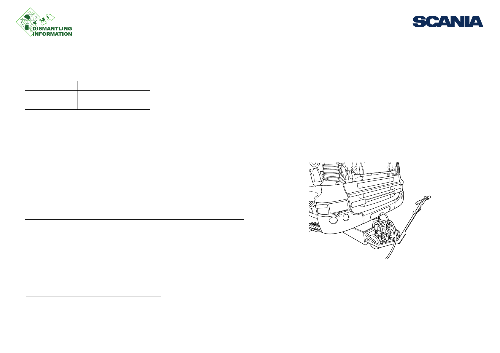
Removing the cab
Note:
211 113
Draining the cooling system
Tools
Examples of suitable tools from Scania:
Part number Designation
99 242 Lifting tool
99 431 Cab strut
Work description
1. Open the upper front grille panel and take out the handle bar which is used to tilt
the cab.
2. Fully tilt the cab, see Instructions, tilting the cab.
3. Fit the cab strut.
4. Separate the gearshift rod at the centre joint and move it aside.
5. Remove the cab strut and tilt the cab back into position.
Tools
Check that the gearshift rod is not broken or damages anything when the cab is lowered.
6. Remove the battery connection.
7. Evacuate the pneumatic system.
8. Drain the cooling system. Refer to the instructions for draining the cooling sys-
tem.
9. Drain the air conditioning.
1. Option
03:21-00 Issue 1 en-GB 1 (13)
1
©
Scania CV AB 2012, Sweden
Page 2
Removing the cab
1 2 3
5 4
211 115
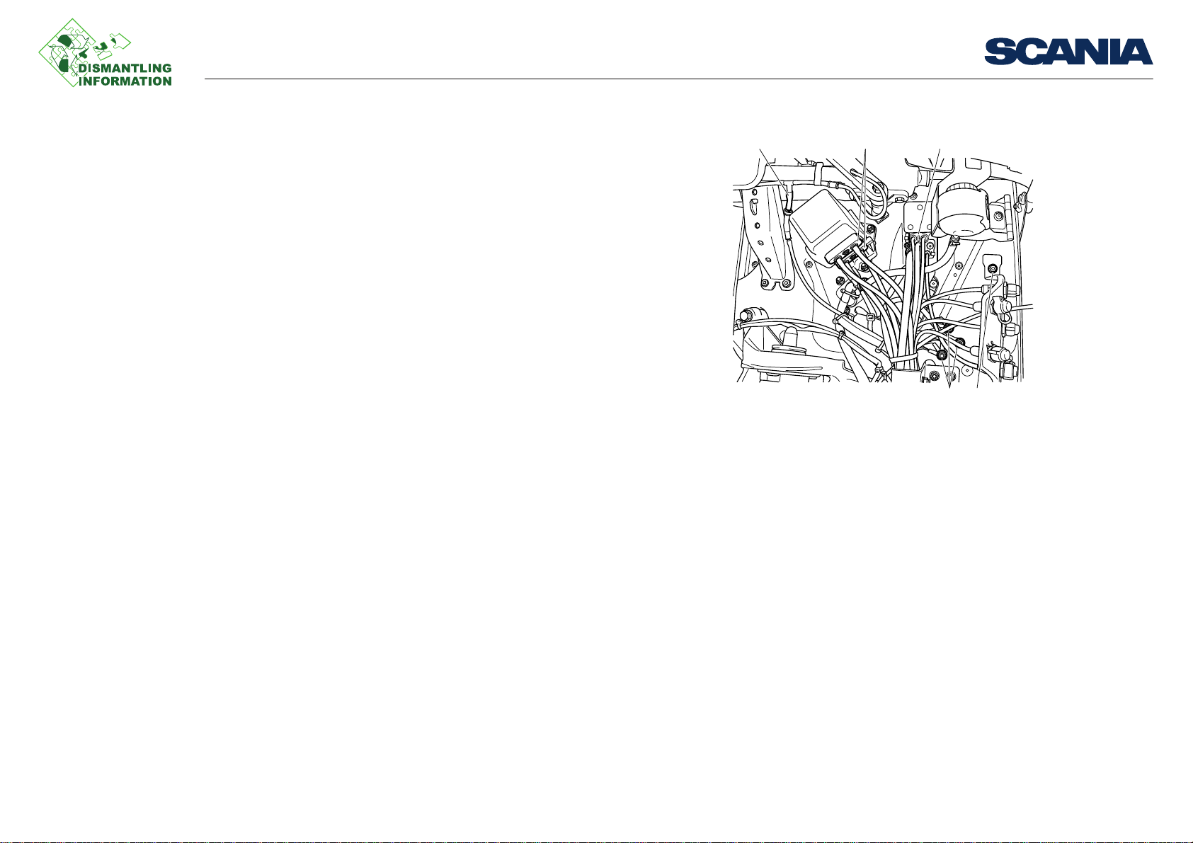
1. Hose
2. Compressed air connection
3. Compressed air connection
4. Bracket
5. Ground connection
Remove parts in the following order:
1. Windscreen washer hose
2. Compressed air connections (brake)
3. Compressed air connections (brake)
4. Test connection bracket
5. Ground connections
Work description
03:21-00 Issue 1 en-GB 2 (13)
©
Scania CV AB 2012, Sweden
Page 3
Removing the cab
211 116
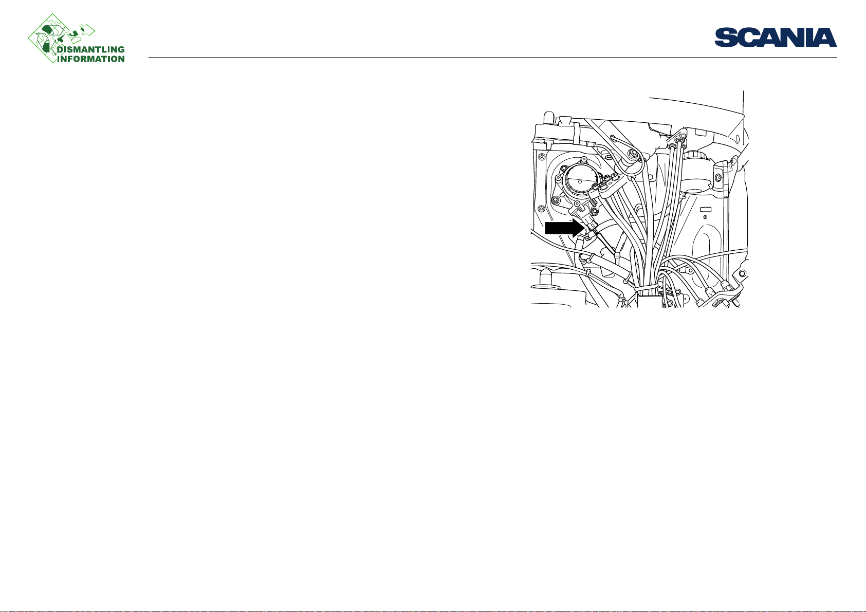
Electrical connection
Then continue to remove parts in the following order:
1. Electrical connection to the brake system.
Work description
03:21-00 Issue 1 en-GB 3 (13)
©
Scania CV AB 2012, Sweden
Page 4
Removing the cab
211 117
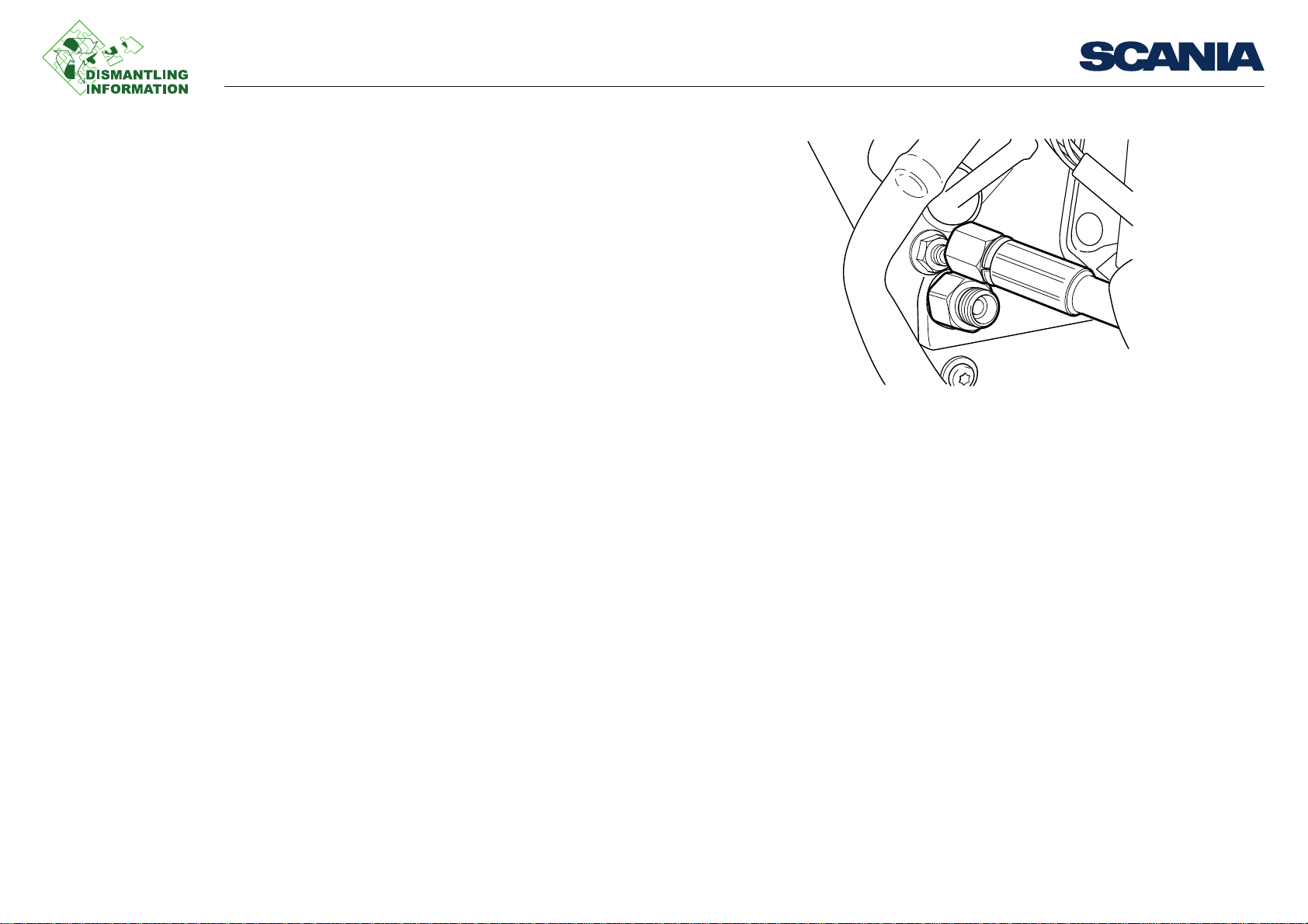
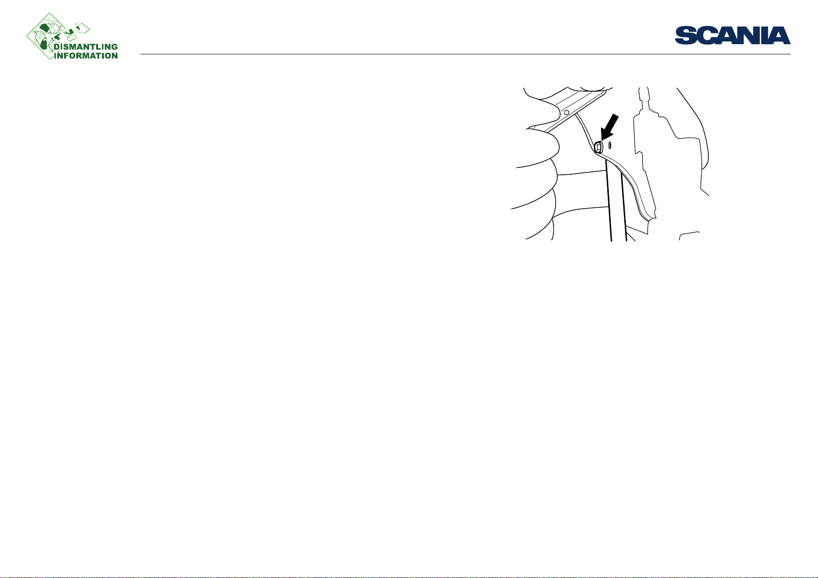
2. Operating hose for servomaster.
Work description
03:21-00 Issue 1 en-GB 4 (13)
©
Scania CV AB 2012, Sweden
Page 5
Removing the cab
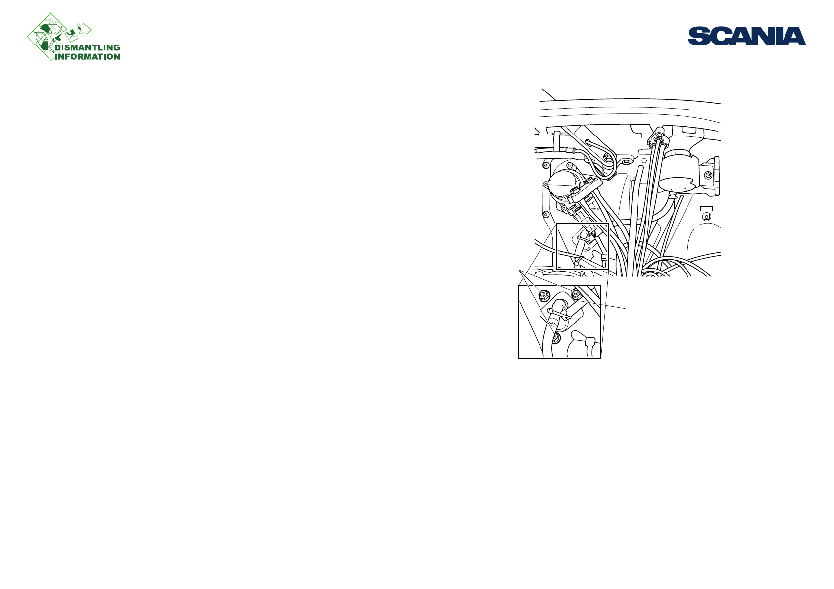
1
2
211 108
1. Nuts
2. Clutch fluid hose
3. Hose for clutch fluid from servomaster. Collect clutch fluid in a suitable contain-
er.
Work description
03:21-00 Issue 1 en-GB 5 (13)
©
Scania CV AB 2012, Sweden
Page 6
Removing the cab
Cable tie
4. Cable ties securing:
– The wires to the front grille panel lock
– The electrical cable for the alarm
– The hoses between the air bellows and the levelling valve
Work description
202 216
03:21-00 Issue 1 en-GB 6 (13)
©
Scania CV AB 2012, Sweden
Page 7

Removing the cab
202 217
202 218
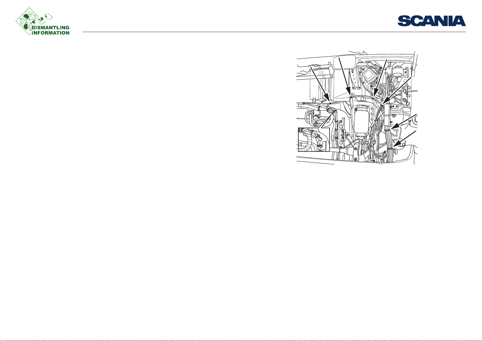
5. Feed hose to the front air bellows at the levelling valve.
6. The link to the levelling valve link arm.
Work description
7. The fuel supply hose to the auxiliary heater.
1
Cut all the cable ties at the same
time.
1. Option
03:21-00 Issue 1 en-GB 7 (13)
©
Scania CV AB 2012, Sweden
Page 8
Removing the cab
201 978
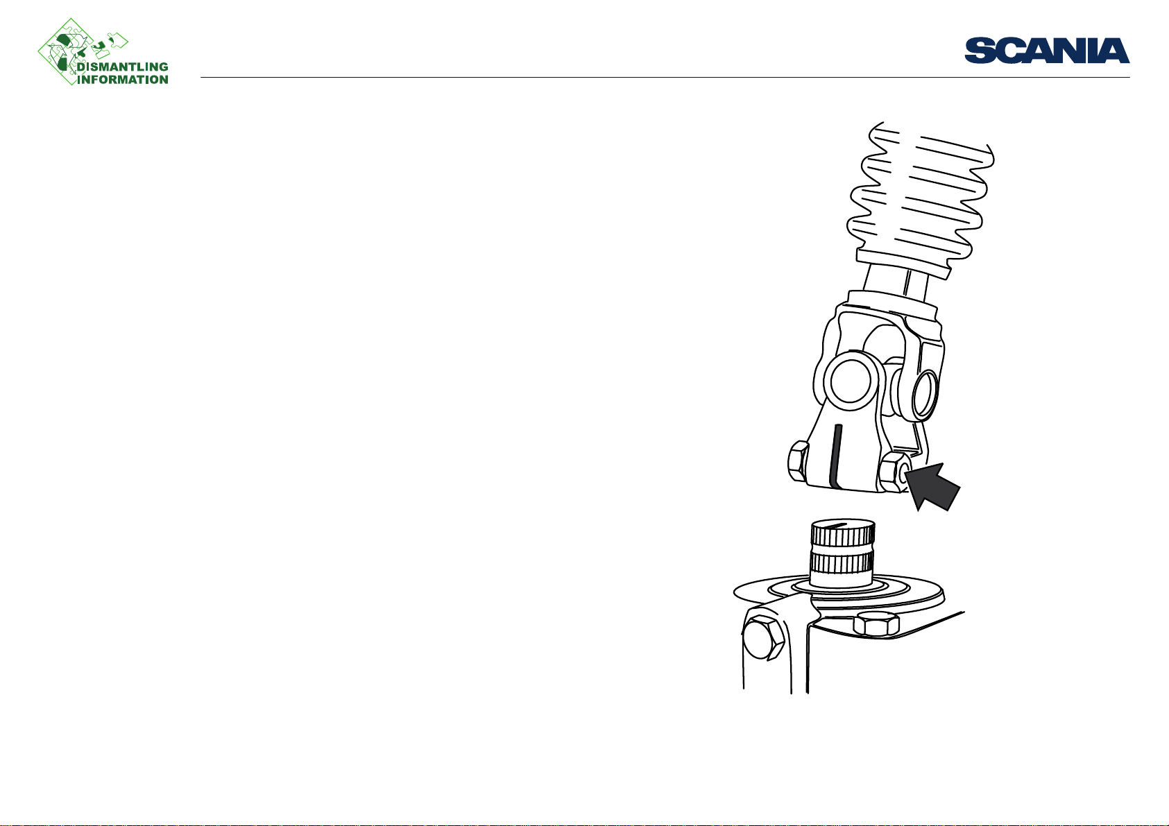
8. Clamp bolt and lower steering wheel shaft universal joint from power steering
gear input shaft.
Work description
03:21-00 Issue 1 en-GB 8 (13)
©
Scania CV AB 2012, Sweden
Page 9
Removing the cab
201 979
202 220
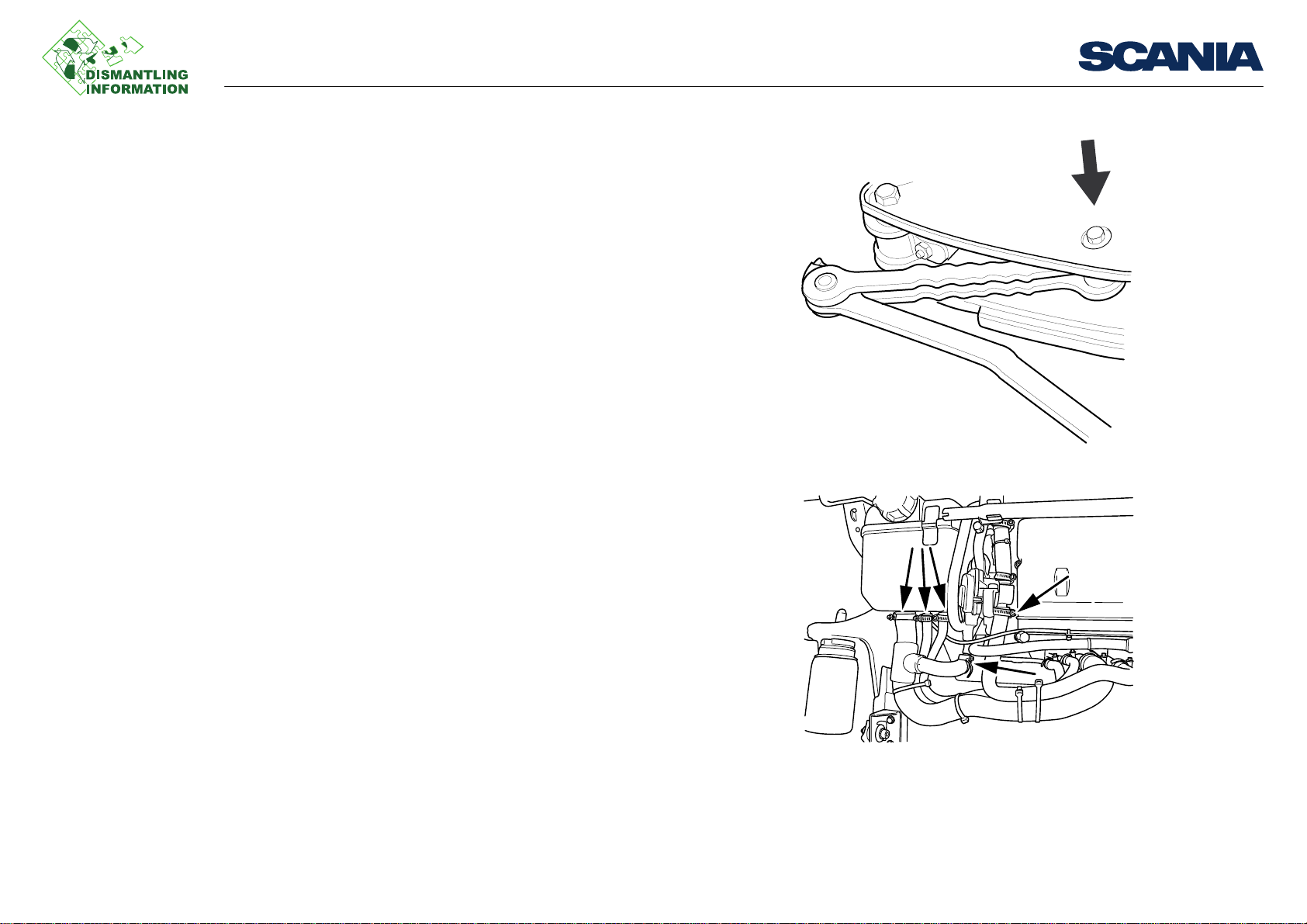
9. Cab tilt stop in upper bracket.
10. Hoses from the underside of the expansion tank and at the water valve.
11. AC pipe at the receiver dryer.
Work description
03:21-00 Issue 1 en-GB 9 (13)
©
Scania CV AB 2012, Sweden
Page 10

Removing the cab
202 221
202 222
12. Bellows from the air intake.
13. Central electric unit cover.
Work description
03:21-00 Issue 1 en-GB 10 (13)
©
Scania CV AB 2012, Sweden
Page 11

Removing the cab
WARNING!
WARNING!
202 223
202 224
14. All connectors, screws for attachment of cable harness in the cab brackets and
ground conections.
Follow the instructions below to lift off the cab:
1. Fit the lifting tool 99 242 and secure the lifting arms using a chain as illustrated.
Make sure no one is inside or nearby the cab when it is lifted off.
Work description
2. Raise the overhead hoist until the cab is hanging in the lifting tool. The cab must
hang horizontally.
If the cab is not hanging horizontally; adjust the lifting tool in the door opening to
achieve equilibrium when lifting the cab.
03:21-00 Issue 1 en-GB 11 (13)
©
Scania CV AB 2012, Sweden
Page 12
Removing the cab
202 225
3. Remove the upper attachment of the cab tilt cylinder.
Work description
03:21-00 Issue 1 en-GB 12 (13)
©
Scania CV AB 2012, Sweden
Page 13

Removing the cab
Note:
202 226
4. Remove the caps on the anti-roll bar.
Check that the anti-roll bar follows along when the cab is lifted off.
5. Lift off the cab.
Work description
03:21-00 Issue 1 en-GB 13 (13)
©
Scania CV AB 2012, Sweden
 Loading...