

Page 1

Removing the gearbox
General
Applies to GA750/751/752 and GA851/852 with variants.
Specifications
The specified weights refer to a gearbox without fluid.
The centre of gravity of the gearbox is approximately at the leading edge of the fluid
filter cover.
Gearbox Weight
GA750/751/752 approx. 260 kg
GA851/852 approx. 410 kg
Gearbox with retarder + approx. 40 kg
Gearbox with power takeoff
+ approx. 30 kg
General
Tools
Examples of suitable tools from Scania:
Part number Designation
99 301 Adapter
99 309 Rotating tool
98 405–1 Fixture beam
98 405–2 Bracket
98 655–9 Beam
99 318 Engine support
82 320 Lifting platform
03:64-00 Issue 1 en-GB 1 (5)
©
Scania CV AB 2012, Sweden
Page 2
Removing the gearbox
99 301
587 129
Part number Designation
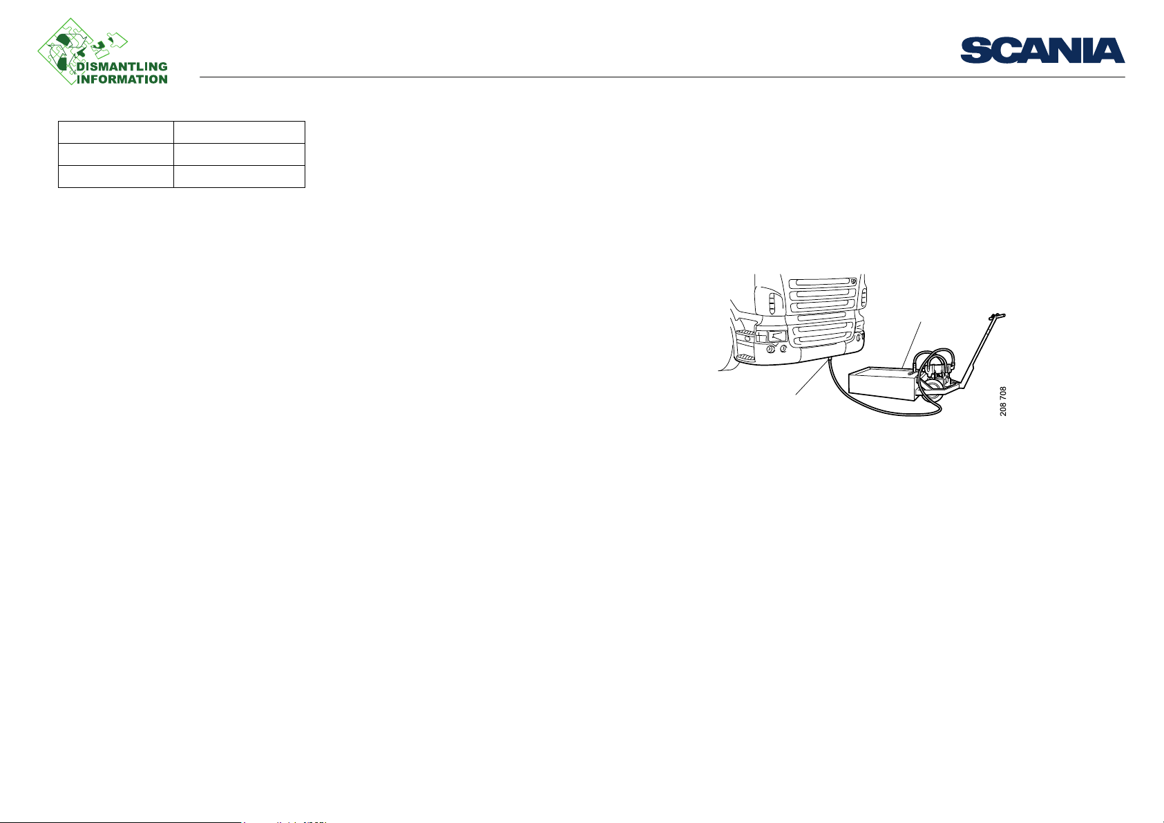
587 129 Coolant tank
587 313 Gearbox jack
Work description
Working from above
1. Drain the coolant from the engine using adapter 99 301 and coolant tank 587 129.
2. Lower the air suspension to its lowest point.
3. Tilt the cab.
4. Detach the coolant hoses at the engine.
5. If the vehicle has an 11 or 12 litre engine: Disconnect the battery. The starter mo-
tor must be removed at a later stage.
Work description
03:64-00 Issue 1 en-GB 2 (5)
©
Scania CV AB 2012, Sweden
Page 3

Removing the gearbox
WARNING!
Connector to road speed sensor.
Connector to accumulator solenoid valve.
Work from below
1. Drain the remaining coolant in the gearbox oil cooler through the drain plug in
the coolant pipe.
2. Refit the drain plug.
3. Detach the coolant hoses at the oil cooler.
4. Detach the connectors for the gearbox and road speed sensor.
If the gearbox is fitted with a retarder: Detach the connector for the accumulator
solenoid valve.
Refer to warning and illustration below.
Work description
• Undo the connector otherwise oil will squirt out when power is applied to the accumulator solenoid valve.
113 564
• Beware of hot oil. Wear protective gloves and goggles.
5. Drain the gearbox oil into a container.
03:64-00 Issue 1 en-GB 3 (5)
©
Scania CV AB 2012, Sweden
Page 4

Removing the gearbox
Oil hose to accumulator
The above fixture parts also fit the component hoist 587 500
6. Detach the oil hoses for the oil cooler. If the gearbox is fitted with a retarder, the
oil hose to the accumulator must also be detached.
7. Undo the front propeller shaft according to instructions below:
– Disconnect the propeller shaft from the gearbox.
– Detach the support bearing bracket from the chassis frame crossmember and
lower the propeller shaft front section.
– Leave the rear section of the propeller shaft in place.
8. Remove any noise shields.
9. On 9 litre engines there is an access hole in the flywheel housing. Such a hole is
missing on 11 and 12 litre engines, so the hole for the starter motor must be used
instead.
– 9 litre engine: Remove the plug in the flywheel housing.
– 11 and 12 litre engines: Remove the starter motor. This will allow you to ac-
cess the screws securing the flex plate onto the torque converter.
10. Remove the 12 screws securing the flex plate into the torque converter through
the access hole in the flywheel housing. Turn the flywheel round to the different
screw positions using rotating tool 99 309.
11. Position beam 98 655-9, bracket and fixture beam 98 405 as well as lifting plate
82 320 on the gearbox jack 587 313. Clamp the gearbox with straps at both front
and back edges.
12. Remove the nuts holding the spacer ring and gearbox to the flywheel housing.
The nuts are fitted on the studs and are through nuts screwed into the flywheel
housing.
13. Lower the gearbox and pull it out. Make sure that the gearbox goes clear of any
obstructions.
14. Remove the spacing ring from the gearbox.
Work description
05_5383
82320
98 655-9
98 405
587 313
b113793
03:64-00 Issue 1 en-GB 4 (5)
©
Scania CV AB 2012, Sweden
Page 5

Removing the gearbox
WARNING!
05_5402
2
4
3
1
1. Engine support 99 318
2. Spacing sleeve
3. Intermediate sleeve
4. Adjusting device
The instructions below applies to GA851/852:
1. Hook 2 engine supports 99 318 onto the front axle beam.
2. Screw the lowest spacing sleeve (2) onto the relevant engine support. Do not
tighten the nuts.
3. Adjust using intermediate sleeves (3) and the threaded adjusting device (4) so the
engine support is at the correct height.
4. Unscrew the 2 oil sump screws, so that the pins of the adjusting device can be
fitted in the screw holes. Select the sump screws so that the intermediate sleeve
(3) ends up behind the centre of the front axle.
5. Adjust the position of the sleeves so that they are as straight as possible and tight-
en the nuts on the lowest sleeve.
6. Screw up the adjusting device (4) so that the support bottoms against the oil
sump.
Never alter the distance between the front axle beam and frame, e.g. by raising the
air suspension. There is a risk that the engine will drop.
Work description
7. Detach the gearbox brackets from the vibration insulators.
8. Raise the gearbox so that there is no tension between the engine and the gearbox.
9. Screw up the adjusting devices on the engine supports.
10. Remove the vibration insulators.
03:64-00 Issue 1 en-GB 5 (5)
©
Scania CV AB 2012, Sweden
 Loading...