

Page 1

Removing Opticruise
1
2
3
4
1. Air hoses
2. Lateral stroke cylinder cover
3. Position sensor
4. Retaining screws
Tools
Examples of suitable tools from Scania:
Part number Designation
99 520 Sleeve for motor shaft
Work description
Lateral stroke cylinder
The vehicle compressed air system need not have pressure to remove the lateral
stroke cylinder.
1. Switch on the power supply. Put the drive mode selector in neutral. Switch off
the power.
2. Remove the air hoses.
3. Undo the screws and remove the lateral stroke cylinder cover.
4. Remove the position sensor.
5. Undo the screws.
Tools
03:71-00 Issue 1 en-GB 1 (6)
©
Scania CV AB 2012, Sweden
Page 2
Removing Opticruise
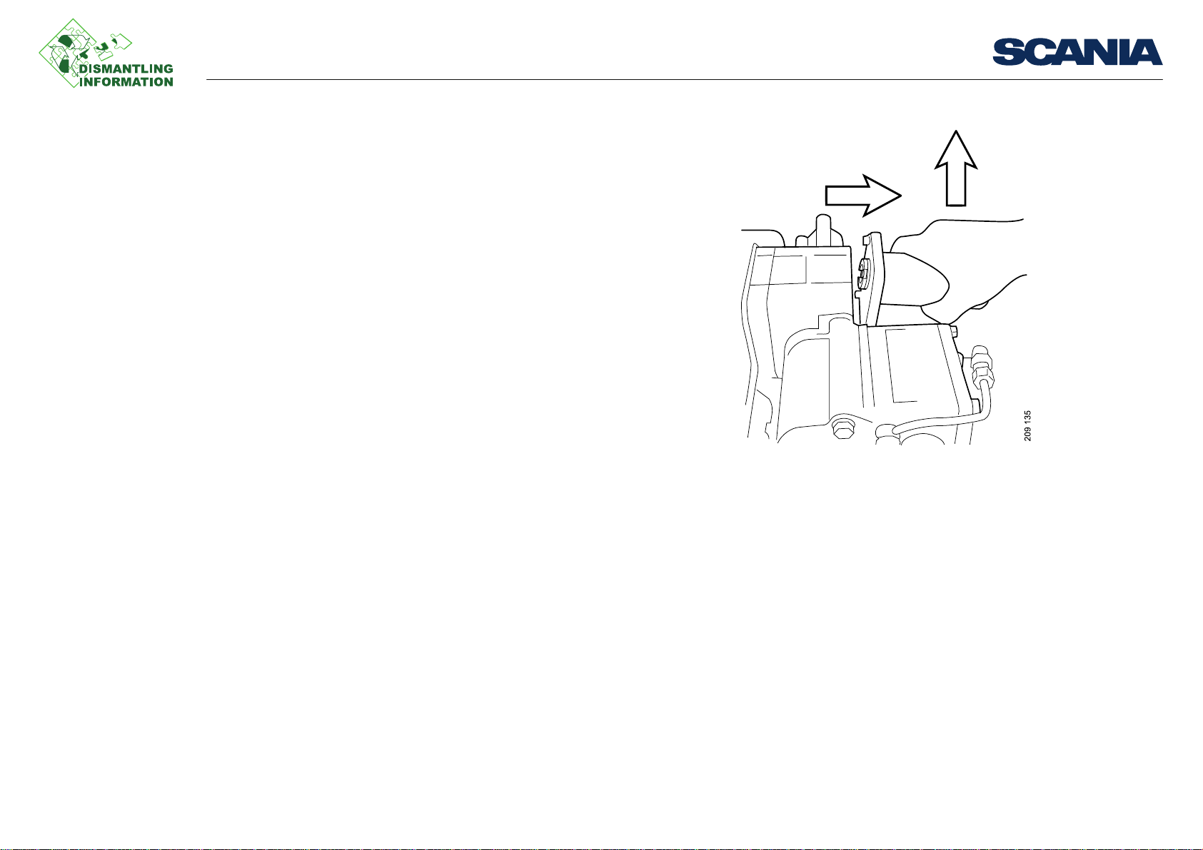
6. Remove the cylinder by pulling it first out and then up.
Work description
03:71-00 Issue 1 en-GB 2 (6)
©
Scania CV AB 2012, Sweden
Page 3

Removing Opticruise
99 520
Removing the lateral stroke cylinder piston
1. Remove the piston retaining ring by carefully prising it out with a screwdriver.
2. Use tool 99 520 to tap the piston out of the lateral stroke cylinder.
Work description
03:71-00 Issue 1 en-GB 3 (6)
©
Scania CV AB 2012, Sweden
Page 4

Removing Opticruise
Work description
Longitudinal stroke cylinder
The vehicle compressed air system must have pressure for the gearbox to be positioned correctly before the longitudinal stroke cylinder is removed.
1. Switch on the power supply. Put the drive mode selector in neutral. This puts the
longitudinal stroke cylinder in neutral. Switch off the power.
2. Remove the air supply hose from the solenoid valve housing.
3. Disconnect the electrical connection to the solenoid valve housing.
4. Remove the air hoses and position sensor from the lateral stroke cylinder.
5. Undo the screws and remove the lateral stroke cylinder and lever.
6. Remove the position sensor from the longitudinal stroke cylinder.
7. Remove the longitudinal stroke cylinder, gearshift housing and sensor housing.
2
73 4
9
12
5
6
8
10
11
333 311
2. Lever 6. Air connections 10. Air hoses
3. Retaining screws 7. Electrical connection 11. Position sensor
4. Sensor housing 8. Oil filler 12. Electrical cable
5. Bracket 9. Air supply
03:71-00 Issue 1 en-GB 4 (6)
©
Scania CV AB 2012, Sweden
Page 5

Removing Opticruise
17
13
14
15
16
13. Pushrod
14. Lever
15. Sleeve
16. Sensor pin
17. Longitudinal stroke damper
The longitudinal stroke damper pushrod and lever
1. Undo the flange screw of the sensor unit.
2. Pull off the sleeve and lever from the pushrod and remove them from the gear-
shift housing.
Work description
03:71-00 Issue 1 en-GB 5 (6)
©
Scania CV AB 2012, Sweden
Page 6

Removing Opticruise
Range and splitter cylinders
1. Remove the electrical connection and compressed air line.
2. Undo the screws from the solenoid valve housing.
3. Remove the solenoid valve housing.
4. Remove the spacers and detach the sensors. GR type gearboxes have a plug in-
stead of a position sensor in the split position.
5. Undo the screws for the cylinder.
6. Remove the cylinder.
Work description
2
6
1
7
5
4
3
8
03:71-00 Issue 1 en-GB 6 (6)
©
Scania CV AB 2012, Sweden
333 307
 Loading...