

Page 1
Property of American Airlines
Scania Engine
Page 2
Important information
WARNING!
IMPORTANT!
Serious risk of injury
When working on the engine, for example when adjusting drive belts and the clutch, or when changing the
oil, it is important not to start the engine. The engine could be damaged, but more importantly there is a
serious risk of injury.
For this reason, always secure the starting device or disconnect a battery cable before working on the engine.
This is especially important if the engine has a remote starter or automatic starting.
This warning symbol and text can be found next to those inspection points where it is particularly important
to bear in mind the risk of injury.
Operator's manual
DC13
XPI
Industrial engine
en-GB 2 397 828
Issue 2.1
The owner is responsible for making sure that inspection is carried out on time and in accordance with the
instructions.
The owner must entrust the maintenance, renewal and repair of emission-related components and systems
to a qualified workshop or person.
Property of American Airlines
Page 3

Start-up Report – Warranty
When the start-up report has been filled in and
sent to Scania, you have a 1-year warranty from
the date of entry into service. Fill in the particulars below as well. This can make things easier if
you need to contact a workshop for example.
Engine serial number
Date of entry into service
User's name and address
Signature
Engine type
Variant
Engine type and variant are indicated on the engine data plate.
Property of American Airlines
OPM 200 en-GB 2
©
Scania CV AB 2014, Sweden
Page 4

Start-up Report – Warranty . . . . . . . . . . . . . . . 2
Introduction . . . . . . . . . . . . . . . . . . . . . . . . . . . . 4
Environment and safety . . . . . . . . . . . . . . . . . . 5
Environmental responsibility . . . . . . . . . . . . . 5
Safety . . . . . . . . . . . . . . . . . . . . . . . . . . . . . . . 5
Warnings and advisories . . . . . . . . . . . . . . . . . 6
Certification . . . . . . . . . . . . . . . . . . . . . . . . . 11
Scania engines engine warranty for industrial
engines . . . . . . . . . . . . . . . . . . . . . . . . . . . . . . . 12
Emission control systems warranty. . . . . . . . 12
Emission control system warranty statement 12
California emission control warranty statement
16
Your warranty rights and obligations . . . . . . 16
Manufacturer's warranty coverage . . . . . . . . 16
Owner's warranty responsibilities . . . . . . . . . 16
SCR catalytic converter . . . . . . . . . . . . . . . . . 17
Engine data plate . . . . . . . . . . . . . . . . . . . . . . . 19
Component identification . . . . . . . . . . . . . . . . 20
SCR system . . . . . . . . . . . . . . . . . . . . . . . . . . 21
Starting and running . . . . . . . . . . . . . . . . . . . . 23
Checks before running . . . . . . . . . . . . . . . . . 23
Starting the engine . . . . . . . . . . . . . . . . . . . . 23
Running . . . . . . . . . . . . . . . . . . . . . . . . . . . . . 24
Engine shutdown . . . . . . . . . . . . . . . . . . . . . . 27
Checks after running . . . . . . . . . . . . . . . . . . . 27
Inspection . . . . . . . . . . . . . . . . . . . . . . . . . . . . . 28
Engines with few hours of operation . . . . . . 29
Cleaning the engine. . . . . . . . . . . . . . . . . . . . 29
Inspection interval . . . . . . . . . . . . . . . . . . . . . 30
Lubrication system . . . . . . . . . . . . . . . . . . . . . 31
Oil grade . . . . . . . . . . . . . . . . . . . . . . . . . . . . 31
Oil analysis . . . . . . . . . . . . . . . . . . . . . . . . . . 32
Checking oil level . . . . . . . . . . . . . . . . . . . . . 32
Changing the oil . . . . . . . . . . . . . . . . . . . . . . 33
Labels for top-up engine oil grade . . . . . . . . 34
Parts. . . . . . . . . . . . . . . . . . . . . . . . . . . . . . . . 34
Cleaning the centrifugal oil cleaner . . . . . . . 35
Operational testing . . . . . . . . . . . . . . . . . . . . 40
Renewing the oil filter. . . . . . . . . . . . . . . . . . 41
Cooling system . . . . . . . . . . . . . . . . . . . . . . . . . 42
Coolant . . . . . . . . . . . . . . . . . . . . . . . . . . . . . 42
Checking coolant level . . . . . . . . . . . . . . . . . 46
Checking antifreeze and corrosion inhibitor . 47
Antifreeze and corrosion inhibitor . . . . . . . . 48
Changing coolant . . . . . . . . . . . . . . . . . . . . . 49
Cleaning the cooling system . . . . . . . . . . . . . 51
Air cleaner . . . . . . . . . . . . . . . . . . . . . . . . . . . . 54
Reading the vacuum indicator. . . . . . . . . . . . 54
Renewing the filter element . . . . . . . . . . . . . 54
Renewing the safety cartridge. . . . . . . . . . . . 55
Fuel system . . . . . . . . . . . . . . . . . . . . . . . . . . . . 56
General information on the XPI fuel system 56
Property of American Airlines
Checking fuel level . . . . . . . . . . . . . . . . . . . .56
Renewing the fuel filter . . . . . . . . . . . . . . . . .57
Bleeding the fuel system . . . . . . . . . . . . . . . .61
Miscellaneous . . . . . . . . . . . . . . . . . . . . . . . . . .62
Checking the drive belt . . . . . . . . . . . . . . . . .62
Checking for leaks . . . . . . . . . . . . . . . . . . . . .64
Checking and adjusting the valve clearance .64
Renewing the reductant filter . . . . . . . . . . . . .67
Cleaning the reductant tank filler filter . . . . .69
Cleaning the reductant tank ventilation filter .69
Diesel . . . . . . . . . . . . . . . . . . . . . . . . . . . . . . . . .69
Composition of the fuel . . . . . . . . . . . . . . . . .69
Sulphur content of fuel. . . . . . . . . . . . . . . . . .70
Temperature dependency of the fuel . . . . . . .72
Reductant for SCR . . . . . . . . . . . . . . . . . . . . . .73
Responsibility and quality requirements . . . .73
Properties . . . . . . . . . . . . . . . . . . . . . . . . . . . .74
Preparing the engine for storage . . . . . . . . . . .75
Handling the engine . . . . . . . . . . . . . . . . . . . .75
Preservative coolant . . . . . . . . . . . . . . . . . . . .76
Preservative fuel . . . . . . . . . . . . . . . . . . . . . . .76
Preservative oil . . . . . . . . . . . . . . . . . . . . . . . .77
Preparations for storage . . . . . . . . . . . . . . . . .77
Technical data . . . . . . . . . . . . . . . . . . . . . . . . . .80
General data . . . . . . . . . . . . . . . . . . . . . . . . . .80
Lubrication system . . . . . . . . . . . . . . . . . . . . .80
Injection system . . . . . . . . . . . . . . . . . . . . . . .81
Cooling system . . . . . . . . . . . . . . . . . . . . . . . .81
Intake system . . . . . . . . . . . . . . . . . . . . . . . . .81
Electrical system . . . . . . . . . . . . . . . . . . . . . .81
Scania Assistance . . . . . . . . . . . . . . . . . . . . . . .82
OPM 200 en-GB 3
©
Scania CV AB 2014, Sweden
Page 5

Introduction
Note:
This Operator's Manual describes the operation
and inspection of Scania industrial engines.
The engines are direct-injection, liquid-cooled,
four-stroke, turbocharged diesel engines. Certain
engines are also equipped with an SCR system
for emission control.
The engines are available with different output
and engine speed settings. The normal output
setting of the engine (performance code) is indicated on the engine data plate.
Only standard components are described in the
operator's manual. Information about special
equipment is contained in instructions from the
various manufacturers.
Introduction
To ensure the maximum performance and the
longest service life for the engine remember the
following:
• Read through the Operator's Manual before
starting to use the engine. Even regular users
of Scania engines will get new information
from the Operator's Manual.
• Always follow the inspection instructions.
• Read the section on safety carefully.
• Get to know your engine so that you know
what it can do and how it works.
• Always contact a workshop with qualified
personnel for inspection and repair.
The information in this manual was correct at the
time of going to press. Scania reserves the right
to make alterations without prior notice.
Property of American Airlines
OPM 200 en-GB 4
©
Scania CV AB 2014, Sweden
Page 6
Environment and safety
WARNING!
IMPORTANT!
Note:
Environment
Environment and safety
Environmental responsibility
Scania develops and produces engines that are as
environmentally-friendly as possible. Scania has
made major investments in the reduction of
harmful exhaust emissions in order to fulfil the
environmental requirements in force in almost
every market.
At the same time, we have been able to maintain
a high level of performance and operating economy for Scania Industrial and Marine Engines.
To maintain these throughout the entire service
life of the engine, it is important for the user to
follow the instructions on running, inspection
and fuel and lubricating oil as outlined in the Operator's Manual.
Other green initiatives taken include ensuring
that, following inspection and repair, waste that
is harmful to the environment (for example oil,
fuel, coolant, filters and batteries) is disposed of
accordance with the applicable environmental
requirements.
Safety
Different types of advisory
Warning!
All advisories preceded by Warning! are very
important. They warn of serious faults and incorrect operation that could lead to personal injury.
Example:
Block the starting device when working on the
engine. If the engine starts unexpectedly, there is
a serious risk of injury.
Important!
Advisories preceded by Important! warn of
faults and incorrect operation that could lead to
equipment being damaged. Example:
For Scania to guarantee that the engine corresponds to its certified configuration, and take responsibility for any damage and injuries that
occur, inspection must be carried out as above.
The following pages contain a summary of the
safety precautions to be complied with when operating and inspecting Scania engines. The
equivalent text can also be found under the relevant inspection point.
To prevent damage to the engine and to ensure
that it runs optimally, follow the instructions in
the warnings and advisories.
If the instructions are not followed, the warranty
can cease to apply.
Property of American Airlines
Note:
Advisories preceded by Note: refer to information important to ensure the best possible operation and functionality. Example:
Leave the engine off for at least 1 minute before
checking the oil level.
Environment
This Operator’s Manual contains specially highlighted text with instructions to help protect the
environment during inspection. Example:
Use a container to avoid spillage.
OPM 200 en-GB 5
©
Scania CV AB 2014, Sweden
Page 7
Environment and safety
WARNING!
WARNING!
WARNING!
WARNING!
IMPORTANT!
Warnings and advisories
Smoking
Smoking is prohibited
• in the vicinity of flammable or explosive material, e.g. fuel, oils, batteries, chemicals
• when refuelling and in the vicinity of the filling station
• when working on the fuel system
Safety precautions for running the
engine
Daily inspection
Always carry out a visual inspection of the engine and engine compartment before starting the
engine or when the engine has been switched off
after operation.
Refuelling
Never overfill the fuel tank as the fuel needs
space to expand. Also ensure that the filler cap is
properly closed.
During refuelling there is a risk of fire and explosion. The engine must be switched off and smoking is prohibited.
Hazardous gases
Only start the engine in a well ventilated area.
The exhaust gases contain carbon monoxide and
nitrogen oxides, which are toxic.
If it is run in an enclosed space, there should be
an effective device to extract exhaust gases and
crankcase gases.
This inspection should be done to detect fuel, oil
or coolant leaks, or anything else that may require corrective action.
Fuel
Use only fuel recommended in the workshop
manual.
The wrong fuel grade can cause breakdowns or
stoppages by causing the injection system to
malfunction. This can cause damage to the engine and, possibly, personal injury.
Property of American Airlines
Starter lock
If the control panel is not fitted with a starter
lock, the engine compartment should be locked
to prevent unauthorised personnel from starting
the engine. Alternatively, a lockable master
switch or battery master switch can be used.
OPM 200 en-GB 6
©
Scania CV AB 2014, Sweden
Page 8
Environment and safety
WARNING!
WARNING!
WARNING!
WARNING!
WARNING!
Environment
Starter gas
Never use starter gas or similar agents to help
start the engine. This can cause an explosion in
the intake manifold and possible injury.
Running
The engine must not be run in environments
where there is a risk of explosion, as all of the
electrical or mechanical components can generate sparks.
Approaching a running engine always poses a
safety risk. Parts of the body, clothes or dropped
tools can get caught in rotating parts such as the
fan and cause injury. For personal safety all rotating parts and hot surfaces must be fitted with
guards.
Batteries
The batteries contain and form oxyhydrogen gas,
particularly during charging. Oxyhydrogen gas
is flammable and highly explosive.
There must be no smoking, naked flames or
sparks near the batteries or the battery compartment. Incorrect connection of a battery cable or
jump lead can cause a spark, which can cause the
battery to explode.
Chemicals
Most chemicals such as glycol, anti-corrosive
agents, preservative oils and degreasing agents,
are hazardous to health.
Some chemicals, such as preservative oil, are
also flammable.
Safety precautions for handling materials
Fuel and lubricating oil
All fuels and lubricants as well as many chemicals are flammable. Always follow the instructions on the relevant packaging.
The work must be carried out on a cold engine.
Fuel leaks and spillage on hot surfaces can cause
fire.
Store used rags and other flammable materials
safely so as to avoid spontaneous combustion.
Property of American Airlines
Always follow the safety precautions on the relevant packaging.
Store chemicals and other materials which are
hazardous to health in approved containers,
marking them clearly and storing them where
they are inaccessible to unauthorised persons.
Always hand in leftover and used chemicals to
an authorised waste disposal contractor.
OPM 200 en-GB 7
©
Scania CV AB 2014, Sweden
Page 9
Environment and safety
WARNING!
WARNING!
WARNING!
WARNING!
Reductant
Reductant (AdBlue/DEF) is used in the reductant
tank on engines equipped with an SCR system.
Avoid contact with the skin.
If reductant comes in contact with the skin: Wash
with soap and plenty of water. If reductant
splashes in the eyes: Rinse immediately with
plenty of water. Contact a doctor if it is ingested
or causes skin irritations.
Safety precautions for inspection
and repair
Switch off the engine
Always switch off the engine before carrying out
inspections and repairs, unless otherwise indicated.
Hot surfaces and fluids
There is always a risk of sustaining burns when
an engine is hot. Particularly hot parts are exhaust manifolds, turbochargers, oil sumps, hot
coolant and oil in pipes and hoses.
Lift the engine out
Always use the engine lifting eyes. Always
check that lifting devices are in good condition
and are designed to lift the weight.
Optional equipment on the engine can change
the centre of gravity. This means that it may be
necessary to use additional lifting devices to balance the engine correctly and lift it safely.
Make it impossible to start the engine: Remove
any starter key, or cut the power using the main
power switch or battery master switch and lock
them.
Fix a warning plate somewhere appropriate,
showing that work is being carried out on the engine.
Working with a running engine always poses a
safety risk. Parts of the body, clothes or dropped
tools can get caught in rotating parts and cause
injury.
Property of American Airlines
Never work underneath a suspended engine!
OPM 200 en-GB 8
©
Scania CV AB 2014, Sweden
Page 10

Environment and safety
WARNING!
Environment
IMPORTANT!
IMPORTANT!
WARNING!
Environment
Batteries
The batteries contain highly corrosive sulphuric
acid. Take care to protect your eyes, skin and
clothes when charging or handling batteries.
Wear protective gloves and goggles.
If sulphuric acid comes in contact with the skin:
Wash with soap and plenty of water. If it gets in
your eyes: Rinse immediately with plenty of water and seek medical attention.
Always hand in used batteries to an authorised
waste disposal contractor.
Electrical system
Electric welding
When carrying out welding work on and near the
engine, disconnect the battery and alternator
leads. Pull out the multi-pin connector for the engine control unit as well.
Connect the welding clamp close to the component to be welded. The welding clamp must not
be connected to the engine, or so that the current
can cross a bearing.
When welding is finished:
1.
Connect the alternator and control unit cables first.
2.
Then connect the batteries.
Lubrication system
The engine must be switched off and the power
disconnected using the master switch or battery
master switch before working on the electrical
system. External power supplies to extra equipment on the engine must also be disconnected.
Scania recommends that Scania spare parts are
used for the fuel and electrical systems. Scania
spare parts are designed to minimise the risk of
fire and explosion.
Property of American Airlines
Hot oil can cause burns and skin irritation. Wear
protective gloves and goggles when changing
hot oil.
Make sure that there is no pressure in the lubrication system before starting work on it.
The oil filler cap must always be in place when
starting and running the engine to prevent oil being ejected.
Always hand in used oil to an authorised waste
disposal contractor.
OPM 200 en-GB 9
©
Scania CV AB 2014, Sweden
Page 11
Cooling system
WARNING!
Environment
WARNING!
WARNING!
Never open the coolant filler cap when the engine is hot. Hot coolant and steam may spray out
and cause burns.
If the cap has to be opened do it slowly and carefully to release the pressure before removing the
cap. Wear gloves as the coolant is still very hot.
Always hand in used coolant to an authorised
waste disposal contractor.
Environment and safety
Fuel system
Always wear protective goggles when testing injectors. Fuel escaping at high pressure can penetrate tissues and cause serious injury.
Scania recommends that Scania spare parts are
used for the fuel and electrical systems. Scania
spare parts are designed to minimise the risk of
fire and explosion.
Before starting
Ensure that all guards are in place before starting
the engine. Ensure that no tools or other objects
have been left on the engine.
The air filter must be fitted before starting the engine. Otherwise there is a risk of objects being
sucked into the compressor impeller or of injury
if you come into contact with the air filter.
Property of American Airlines
OPM 200 en-GB 10
©
Scania CV AB 2014, Sweden
Page 12

Certification
IMPORTANT!
An emissions certified engine fulfils the emissions requirements for a particular range of application.
On each emissions certified engine there is a label which shows which requirements the engine
fulfils. Scania guarantees that each such engine
fulfils the emissions requirements for the range
of application for which it is certified.
The following are required for the certified engine to fulfil the emissions requirements once it
has been taken into service:
• Inspection is to be carried out in accordance
with the instructions in this Operator's Manual.
• The inspection and repair of injection equipment are to be carried out by a qualified
workshop or person.
• The engine may only be modified with equipment that has been approved by Scania.
• Seals may be broken and setting data edited
only once approval has been granted by Scania. Modifications may be made by authorised personnel only.
• Modifications affecting the exhaust and intake systems must be approved by Scania.
Environment and safety
Otherwise, the instructions in the Operator's
Manual for the running and inspection of the engine shall apply. The safety precautions should
be observed.
For Scania to guarantee that the engine corresponds to its certified configuration, and take responsibility for any damage and injuries that
occur, inspection must be carried out as above.
Property of American Airlines
OPM 200 en-GB 11
©
Scania CV AB 2014, Sweden
Page 13

Scania engines engine warranty for industrial engines
IMPORTANT!
Scania engines engine warranty for industrial engines
Emission control systems warranty
Only applicable to engines used in the U.S.A.
Table of Contents
General warranty provisions 12
Warranty period 12
Parts covered by the Warranty 13
General warranty limitations 14
Specific warranty exclusions 15
Customer support 15
in the engine manufacturer's application for
certification.
Where a warrantable condition exists, Scania
will repair your heavy-duty off-road engine at no
cost to You including diagnosis, parts, and labor.
Warranty period
This warranty shall apply for one of the following periods, whichever occurs first:
• 3,000 hours of operation as determined by a
device to measure hours of use, or
• Five years
Each engine is equipped with a device to measure hours of use. If that device fails to account for
hours of use due to defects in materials or workmanship, the engine shall be warranted for a period of five years. The warranty period shall
begin on the date the engine is delivered to the
first ultimate purchaser who, in good faith, purchases the engine for purposes other than imminent resale.
Emission control system warranty statement
General warranty provisions
The emission control systems of your new Scania Engines (“Scania”) industrial diesel engine
were designed, built and tested using genuine
parts, and were certified as being in conformity
with federal emission control regulations. Scania
warrants to the original owner, and to each subsequent owner, of a new Scania industrial diesel
engine (“You”) that the engine:
1.
Was designed, built and equipped so as to
conform at the time of sale with all applicable regulations under Section 213 of the
Clean Air Act, 42 U.S.C. § 7547, for their
full useful life and designed, built and
equipped so as to conform with all applicable
regulations adopted by the California Air Resources Board pursuant to its authority under
Chapters 1 and 2, Part 5, Division 26 of the
California Health and Safety Code, and;
2.
Is free from defects in material and workmanship which would cause such engine to
fail to conform to applicable regulations for
its warranty period or otherwise cause the
failure of a warranted part to be identical in
all material respects to the part as described
Property of American Airlines
The Warranty on emission-related
parts shall be interpreted as follows:
1.
Any warranted part which is not scheduled
for replacement as required maintenance in
Scania's written instructions for maintenance
and use of the engine by owner shall be warranted for the warranty period defined above.
If any such part fails during the period of
warranty coverage, it shall be repaired or replaced by the engine manufacturer according
to Subsection (4) below. Any such part repaired or replaced under the Warranty shall
be warranted for the remaining warranty period.
2.
Any warranted part which is scheduled only
for regular inspection in Scania's written instructions for maintenance and use of the engine by owner shall be warranted for the
warranty period defined above. A statement
in such written instructions to the effect of
“repair or replace as necessary” shall not reduce the period of warranty coverage. Any
such part repaired or replaced under warranty shall be warranted for the remaining warranty period.
OPM 200 en-GB 12
©
Scania CV AB 2014, Sweden
Page 14

Scania engines engine warranty for industrial engines
Any warranted part which is scheduled for
3.
replacement as required maintenance in Scania's written instructions for maintenance
and use of the engine by owner shall be warranted for the period of time prior to the first
scheduled replacement point for that part. If
the part fails prior to the first scheduled replacement, the part shall be repaired or replaced by the engine manufacturer according
to Subsection (4) below. Any such part repaired or replaced under warranty shall be
warranted for the remainder of the period
prior to the first scheduled replacement point
for the part.
4.
Repair or replacement of any warranted part
under the warranty provisions of this article
shall be performed at no charge to the owner
at a warranty station.
5.
Notwithstanding the provisions of Subsection (4) above, warranty services or repairs
shall be provided at all manufacturer distribution centers that are franchised to serve the
subject engines.
6.
The owner shall not be charged for diagnostic labor that leadsto the determination that a
warranted part is in fact defective, provided
that such diagnostic work is performed at a
warranty station.
7.
The engine manufacturer shall be liable for
damages to other engine components proximately caused by a failure under warranty of
any warranted part.
8.
Throughout the engine's warranty period defined above, the engine manufacturer shall
maintain a supply of warranted parts sufficient to meet the expected demand for such
parts.
9.
Any replacement part, as defined in Section
1900(b), Title 13 of the California Code of
Regulations, may be used in the performance
of any maintenance or repairs and must be
provided without charge to the owner. It is
not necessary for replacement parts to be the
same brand or by the same manufacturer as
the original part sold with the engine. Such
Property of American Airlines
use shall not reduce the warranty obligations
of the engine manufacturer.
10.
Add-on or modified parts, as defined in Section 1900(b), Title 13 of the California Code
of Regulations, that are not exempted by the
California Air Resources Board may not be
used. The use of any non-exempted add-on
or modified parts shall be grounds for disallowing a warranty claim made in accordance
with this article. The engine manufacturer
shall not be liable under this article to warrant failures of warranted parts caused by the
use of a non-exempted add-on or modified
part.
11.
The Executive Officer of the California Air
Resources Board may request, and in such
case, the engine manufacturer shall provide,
any documents which describe that manufacturer's warranty procedures or policies.
Parts covered by the Warranty
The following is a list of parts considered to be
part of the Emission Control Systems covered by
the Emission Warranty for Scania industrial engines which were built to conform to federal and
California emission control regulations:
1.
Fuel injection system.
2.
Air induction system.
3.
Exhaust manifold system.
4.
Smoke puff limiter (included in ECU).
5.
Oil filler cap.
6.
EGR system (when applicable):
a)
Cooler.
b)
EGR valve.
7.
Exhaust brake (when applicable).
8.
NOx sensors:
a)
NOx sensor, engine out.
b)
NOx sensor, tail pipe.
9.
DOC (when applicable).
10.
SCR system:
a)
DEF tank.
b)
DEF tank level, temperature and quality
sensors.
c)
DEF hose.
d)
DEF injector.
e)
DEF injector pressure and temperature
sensors.
f)
Evaporator.
g)
SCR catalyst inlet temperature sensor.
h)
SCR catalyst including the ammonia-slip
catalyst.
i)
SCR control unit (EEC3).
OPM 200 en-GB 13
©
Scania CV AB 2014, Sweden
Page 15

Scania engines engine warranty for industrial engines
IMPORTANT!
WARNING!
Miscellaneous items used in the above sys-
11.
tem:
a)
Electronic control unit (ECU), sensors,
wiring harnesses.
b)
Hoses, belts, connectors, assemblies,
clamps, fittings tubing, sealing gaskets or
devices and mounting hardware.
c)
Pulleys, belts and idlers.
d)
Emission control information label.
This list does not include all expendable maintenance parts.
• Expendable emission related parts requiring
scheduled maintenance are warranted until
their first scheduled replacement point.
• Emission related parts scheduled for inspection and replacement only as necessary are
not considered expendable and if repaired or
replaced under warranty shall be warranted
for the remaining warranty period.
See Specific Warranty Exclusions below.
Receipts covering the performance of regular
maintenance should be retained in the event
questions arise concerning maintenance. The receipts should be transferred to each subsequent
owner of the engine with the emission warranted
engine. Scania cannot, however, deny warranty
solely for the lack of receipts or for your failure
to ensure the performance of all scheduled maintenance.
The Warranty covers the cost of diagnosis, repair
and replacement parts and services of warranted
components and systems performed by an authorized Scania distributor or dealer using genuine Scania parts. You may elect to have
maintenance, replacement or repair of these
components and systems performed by any repair establishment or individual without invalidating the Warranty.
The use of other than Scania replacement parts
also does not invalidate the warranty on other
components unless such parts cause damage to
warranted parts. However, the cost of such services or parts will not be covered by the Warranty.
General warranty limitations
To retain the dependability of the exhaust emission control originally built into your Scania industrial diesel engine, it is essential that the
engine is installed according to Scania installation instructions and emission certificates. Your
engine is designed to operate on diesel fuel only.
Use of any other fuel may result in your engine
no longer operating in compliance with state or
federal emissions requirements. The use of alternative fuels shall not void the warranties on any
engine certified to use such fuel.
In addition, as the engine owner, You are responsible for the performance of all scheduled maintenance listed in your owner's manual, and all
necessary repairs, on your new Scania industrial
diesel engine. Scania may deny a warranty claim
if the engine or part has failed due to abuse, neglect, improper maintenance or unapproved
modifications.
Property of American Airlines
You are responsible for initiating the warranty
process. The California Air Resources Board
suggests that You present your heavy-duty offroad engine to an authorized Scania dealer as
soon as a problem exists. The warranty repairs
should be completed by the dealer as expeditiously as possible.
Use of replacement parts which are not of equivalent quality may impair the effectiveness of
emission control systems. Accordingly, it is recommended that only Scania repair or replacement parts be used for maintenance, repair or
replacement of emission control systems.
If other than Scania parts are used for maintenance, repair or replacement, the owner should
obtain assurance that such parts are warranted by
their manufacturer to be equivalent to genuine
Scania parts.
OPM 200 en-GB 14
©
Scania CV AB 2014, Sweden
Page 16

Scania engines engine warranty for industrial engines
Specific warranty exclusions
This warranty does not cover:
1.
.Malfunctions in any part caused by any of
the following: misuse, abuse, improper adjustments, modifications, alteration, tampering, disconnection, improper or inadequate
maintenance, or use of fuels not recommended for the engine as described in the Operator's Manual.
2.
Engine installation, including cooling system, intake system and exhaust system installation, that is not completed in
accordance with the Scania installation instructions and emissions certificate for this
engine type.
3.
Damage resulting from accidents, acts of nature or other events beyond the control of
Scania.
4.
The replacement of expendable maintenance
items such as filters, hoses, belts, oil, thermostat, exhaust system and coolant made in
connection with scheduled maintenance services once these parts have been replaced.
5.
Replacement items which are not genuine
Scania parts or not authorized by Scania.
6.
Inconvenience, loss of use of the engine or
commercial loss.
7.
Any engine on which the actual use cannot
be accurately determined due to a failure of
the device to track hours of use unrelated to
defects in materials or workmanship.
8.
Any engine operating outside the United
States.
Customer support
In the event that You do not receive the warranty
service to which You believe You are entitled
under the Warranty, or if You need additional
support or information concerning the Warranty,
please contact:
Scania USA, Inc.
Address: 121 Interpark Blvd, suite 1002, 78216,
San Antonio, Texas
Mailing address: 121 Interpark Blvd, suite
1002, 78216, San Antonio, Texas
Telephone: +1 210 403 0007
Fax: +1 210 403 0211
E-mail: contact@scaniausainc.com
California customers shall also be furnished a
copy of the California Emission Control Warranty Statement applicable to each new Scania engine purchased.
Property of American Airlines
OPM 200 en-GB 15
©
Scania CV AB 2014, Sweden
Page 17

California emission control warranty statement
California emission control
warranty statement
Your warranty rights and obligations
The California Air Resources Board is pleased to
explain the emission control system warranty on
your 2015 engine. In California, new heavy-duty
off-road engines must be designed, built and
equipped to meet the State's stringent anti-smog
standards. Scania CV AB must warrant the
emission control system on your engine for the
periods of time listed below provided there has
been no abuse, neglect or improper maintenance
of your engine.
Your emission control system may include parts
such as the fuel injection system and the air induction system. Also included may be hoses,
belts, connectors and other emission-related assemblies.
Where a warrantable condition exists,
Scania CV AB will repair your heavy-duty offroad engine at no cost to you including diagnosis, parts and labor.
Owner's warranty responsibilities
• As the off-road engine owner, you are responsible for the performance of the required
maintenance listed in your owner's manual.
Scania CV AB recommends that you retain
all receipts covering maintenance on your
off-road engine, but Scania CV AB cannot
deny warranty solely for the lack of receipts
or for your failure to ensure the performance
of all scheduled maintenance.
• As the off-road engine owner, you should
however be aware that Scania CV AB may
deny you warranty coverage if your off-road
engine or a part has failed due to abuse, neglect, improper maintenance or unapproved
modifications.
• Your engine is designed to operate on ultra
low-sulfur diesel fuel only. Use of any other
fuel may result in your engine no longer operating in compliance with California's emissions requirements.
• You are responsible for initiating the warranty process. The ARB suggests that you present your off-road engine to a Scania CV AB
dealer as soon as a problem exists. The warranty repairs should be completed by the
dealer as expeditiously as possible.
Manufacturer's warranty coverage
The 2015 heavy-duty off-road engines are warranted for a period of five years or 3,000 hours,
whichever occurs first. If any emission-related
part on your engine is defective, the part will be
repaired or replaced by Scania CV AB.
Property of American Airlines
If you have any questions regarding your warranty rights and responsibilities, you should contact Scania U.S.A. Inc +1-210-403-0007.
OPM 200 en-GB 16
©
Scania CV AB 2014, Sweden
Page 18

SCR catalytic converter
WARNING!
SCR catalytic converter
The SCR catalytic converter contains vanadium
pentoxide, a chemical known to the State of California to cause cancer.
The SCR catalytic converter is fitted in the silencer and does not constitute a health hazard
during normal use and handling.
When carrying out work on the SCR catalytic
converter which may result in exposure to dust,
safety precautions must be taken. Such work includes, for example, opening the silencer machining and scrapping the SCR catalytic
converter.
Safety precautions when working on the SCR
system.
• Inhalation: If dust is inhaled, the person
should be provided with fresh air immediately. Seek medical attention
• Eye contact: Rinse eyes with water immediately. If irritation persists, seek medical attention.
• Skin contact: Wash with water and soap. Remove contaminated clothes.
• Ingestion: If large amounts have been ingested, drink plenty of water and induce vomiting. Seek medical attention
Environmental hazards
• Vanadium pentoxide is toxic to water organisms and can cause detrimental long term effects to water environment.
Environmental protection measures
• The SCR catalytic converter is a manufactured article that contains vanadium pentoxide, a hazardous substance. Before disposing
of, or scrapping, a spent SCR catalytic converter, it should be tested for any hazardous
characteristics (ignitability, corrosivity, reactivity, acute hazardousness, and toxicity), as
those categories are described in 22 CCR §
66261.30. If the spent SCR catalytic converter exhibits hazardous characteristics and is
being disposed of, it will be considered by the
State of California to be a hazardous waste
subject to Title 22, California Code of Regulations. Before disposing of hazardous waste,
review and follow all pertinent federal and
California requirements.
• Vanadium pentoxide is a listed commercial
chemical product - P120 - pursuant to 22
CCR § 66261.33(e). According to the State of
California, commercial chemical products
that are discarded or intended to be discarded
are hazardous wastes and are subject to all
provisions of Title 22, California Code of
Regulations. Before disposing of vanadium
pentoxide, review and follow all pertinent
federal and California requirements.
• If the SCR catalytic converter is opened for
maintenance, any dust spillages from the catalyst should be collected and tested for the
presence of vanadium pentoxide prior to
proper disposal. Dust spillages should also be
tested for any hazardous characteristics (ignitability, corrosivity, reactivity, acute hazardousness, and toxicity), as those categories
are described in 22 CCR § 66261.30, prior to
proper disposal. If the dust contains either vanadium pentoxide or exhibits hazardous characteristics and is being disposed of, it will be
considered by the State of California to be a
hazardous waste subject to Title 22, California Code of Regulations. Before disposing of
hazardous waste, review and follow all pertinent federal and California requirements.
Property of American Airlines
OPM 200 en-GB 17
©
Scania CV AB 2014, Sweden
Page 19

SCR catalytic converter
WARNING!
• Do not dispose of the spent SCR catalytic
converter or its constituent parts into any waterways, storm drains or sanitary sewers.
The SCR catalytic converter contains vanadium
pentoxide, a chemical known to the State of California to cause cancer.
Additional considerations when working on the
SCR system
• Carry out work on the SCR catalytic converter in all well ventilated area. Use protective
goggles and gloves if there is any risk of
splashing or spraying of reductant or coolant.
• When engine is running, the exhaust system
parts can reach such high temperatures that
there is a risk of personal injury. Make sure
that the exhaust system temperature has decreased to a suitable level before starting to
work.
• The SCR system is heated by water from the
engine cooling system. The cooling system
runs at overpressure and when the engine is
hot the coolant is hot. Do not open any hoses
without first stopping the coolant flow in the
hose.
• A P3 type respirator/filter mask or a type
FFP3 fine dust musk, protective goggles and
gloves should be used for any work where
there is a risk of exposure to dust from the
SCR catalytic converter.
• Use a disposable overall and dispose of it
properly after machining.
• Eating, drinking or smoking while working is
not permitted.
• Any dust from the SCR catalytic converter
should be removed using a vacuum cleaner
with microfilter to minimize exposure.
• Make sure that the work surface is cleaned after completed work; Vacuum first then swab.
• Make sure you clean your hands after working with SCR catalytic converter to avoid ingestion.
• Work done on the SCR catalytic converter
may generate waste considered by the State
of California to be a hazardous waste subject
to Title 22, California Code of Regulations.
Before disposing of hazardous waste, review
and follow all pertinent federal and California
requirements.
Property of American Airlines
OPM 200 en-GB 18
©
Scania CV AB 2014, Sweden
Page 20

Engine data plate
Made by
Type
Engine No
Output. kW rpm.
DC13 070A
6950106
331
Ty p e a p pr o va l No :
e 5 x 97 / 68 L Ax 2 00 4 /2 6 x0 14 2 x0 0
2100
319 989
Example of an engine data plate
The engine data plate indicates, in the form of a
code, the engine type, its size and applications.
The engine EU type approval for exhaust emissions is indicated under Output, where applicable.
The engine serial number is stamped onto the top
of the cylinder block at the front right.
Example: DC13 070A
DC Supercharged diesel engine with air-cooled charge air cooler.
13 Displacement in whole dm3.
070 Performance and certification code. The code indicates, together
with the application code, the normal gross engine output.
A Code for application. A means for general industrial use.
Engine data plate
Property of American Airlines
OPM 200 en-GB 19
©
Scania CV AB 2014, Sweden
Page 21
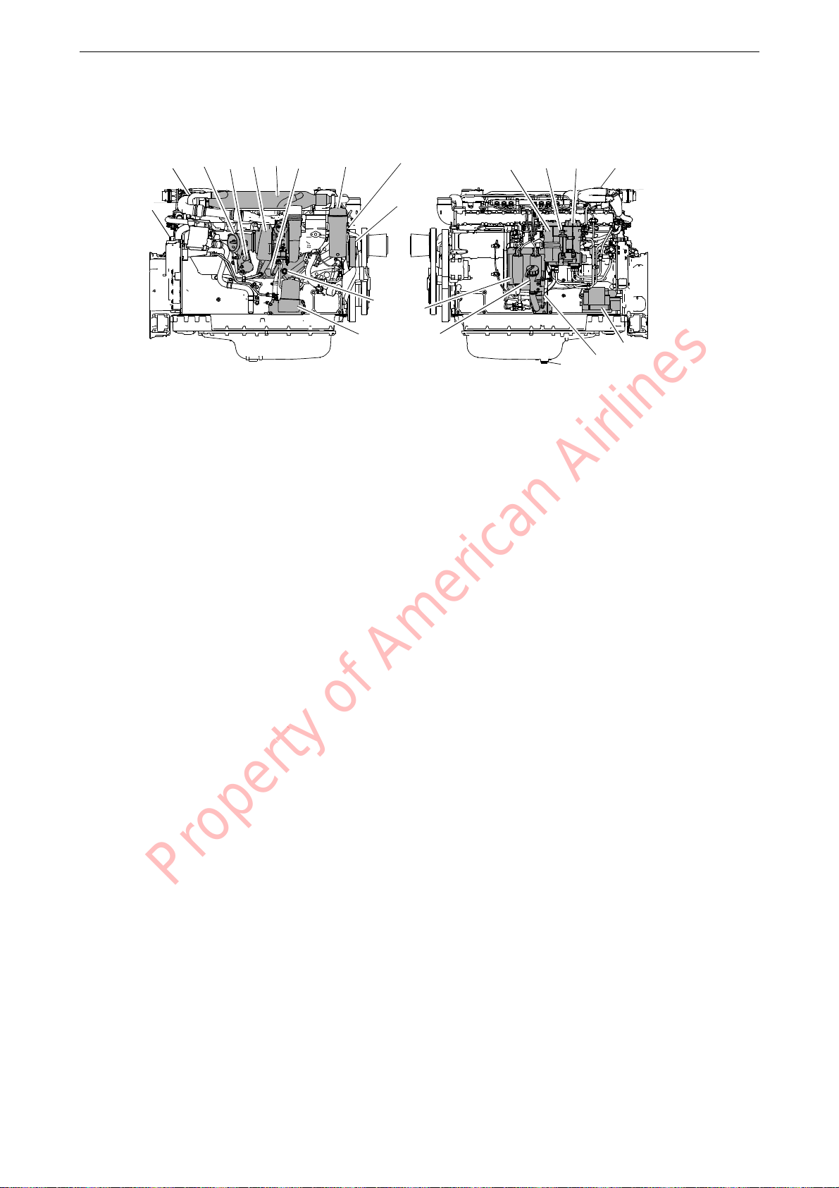
Component identification
336 872
1
2 3 4 5 6 7 8 9
10
11
12 13
14
15 16 17 13
18
1920
The illustration shows a normal version of a DC13 engine. The engine ordered may have different equipment
Component identification
1.
Engine data plate
2.
EGR valve
3.
Exhaust brake
4.
Actuator
5.
Turbocharger
6.
EGR cooler
7.
Oil cooler
8.
Oil filter
9.
Engine serial number on the cylinder
block
10.
Coolant pump
11.
Draining coolant
12.
Centrifugal oil cleaner
13.
Oil filler
14.
Engine control unit
15.
Water separating prefilter for fuel
16.
Hand pump for fuel
17.
Fuel filter
18.
Starter motor
19.
Oil dipstick
20.
Oil plug
Property of American Airlines
OPM 200 en-GB 20
©
Scania CV AB 2014, Sweden
Page 22
SCR system
6
11
5
9
4
13
3
8
7
10
2
12
1
14
336 907
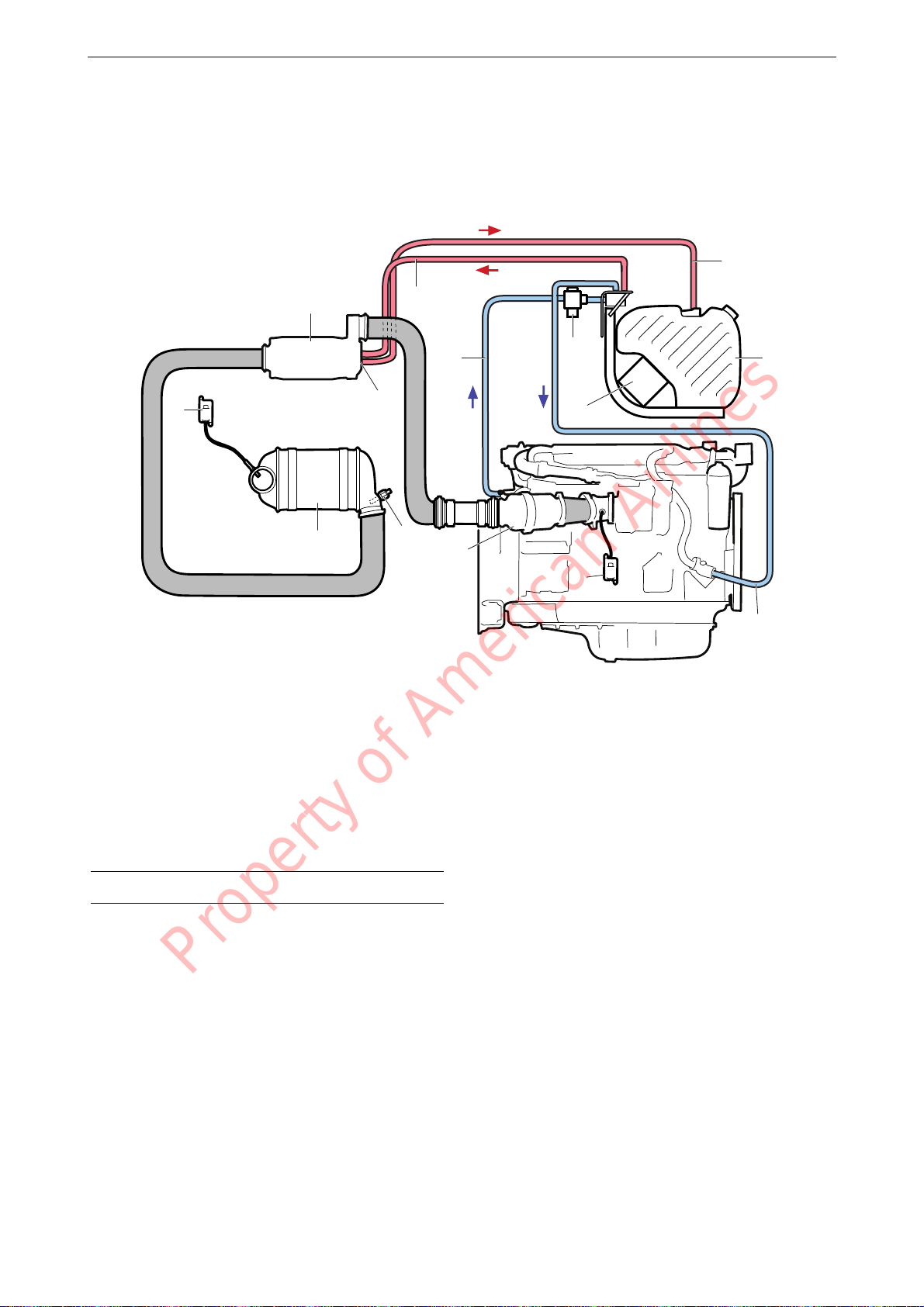
The illustration provides an overview of SCR
system components.
Component identification
1.
Evaporator
2.
Pressure line for reductant
3.
Coolant hose for tank and pump heating
4.
Coolant valve
5.
Reductant return line
6.
Reductant tank
7.
Reductant pump and control unit
1. DC13 084/085/087/089A only.
2. DC13 084/087/089A only.
Property of American Airlines
8.
Coolant hose, return from tank and pump heating
9.
NOx sensor with control unit
10.
Oxidation catalytic converter
11.
Exhaust gas temperature sensor
12.
SCR catalytic converter
13.
NOx sensor with control unit
14.
Reductant doser
1
2
OPM 200 en-GB 21
©
Scania CV AB 2014, Sweden
Page 23
Reductant tank
319 991
38 litres (10 US gallons)
319 992
60 litres (15.8 US gallons)
340 426
69 litres (18.2 US gallons)
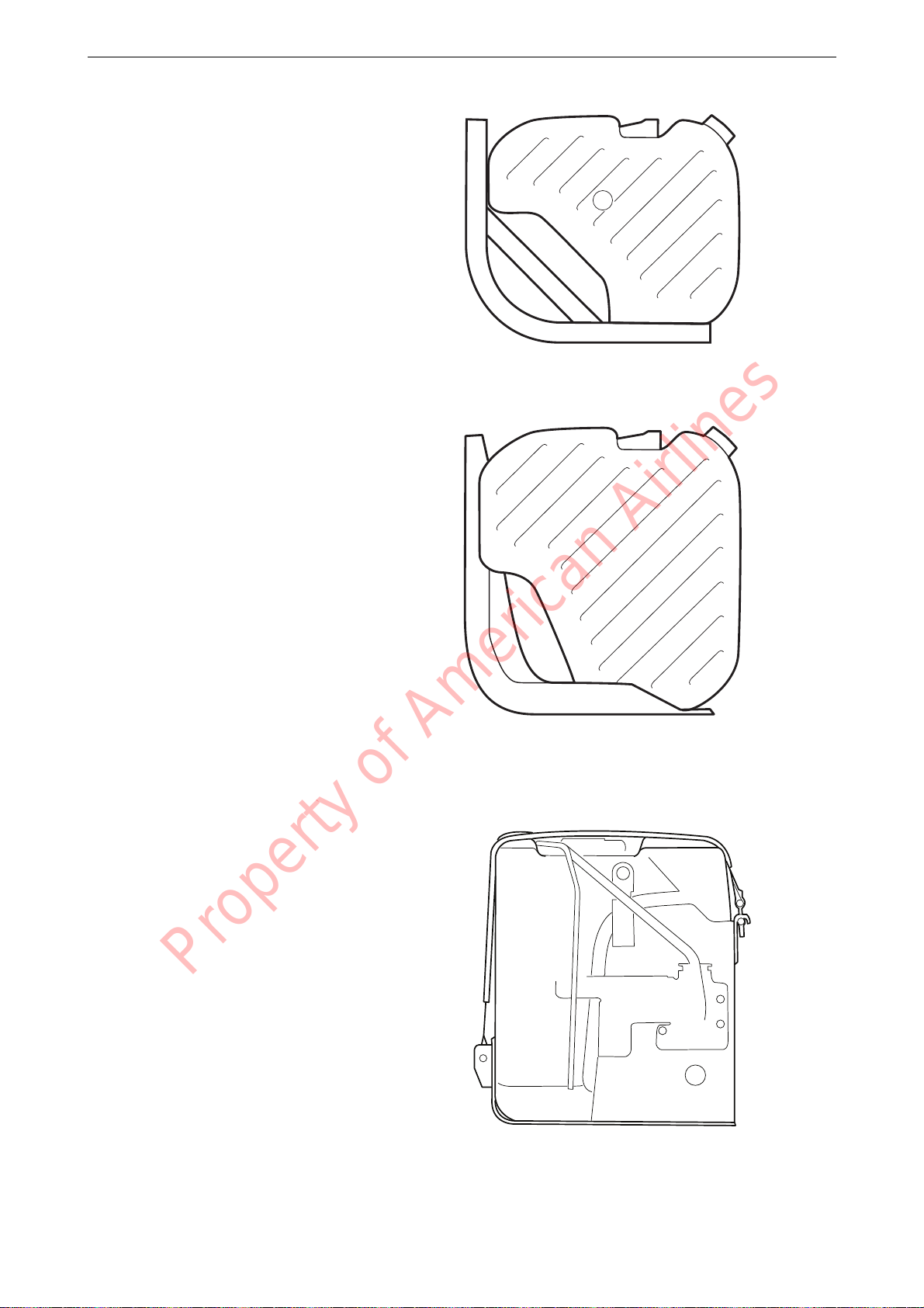
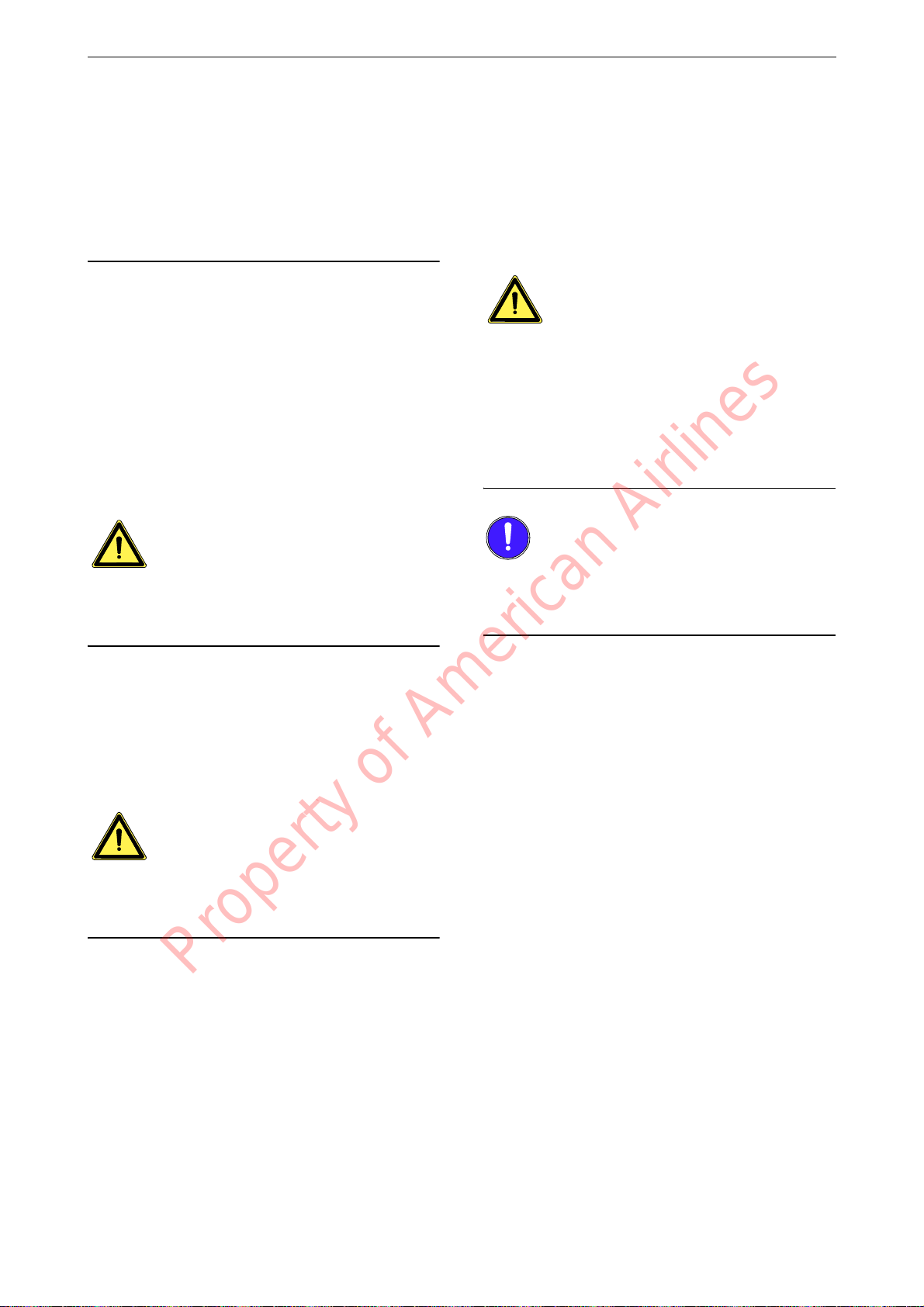
The reductant tank comes in 3 sizes. The volumes indicated for each tank are filling volumes.
The total volume is approx. 10 litres (2.6 US gallons) greater.
A filler filter with magnet is fitted in the reductant tank to prevent the reductant from becoming
contaminated when topping up. The filler filter
with magnet is used when topping up at a filling
station.
A filler filter without a magnet is also supplied
for use when manually topping up reductant.
Component identification
OPM 200 en-GB 22
Property of American Airlines
©
Scania CV AB 2014, Sweden
Page 24
Starting and running
Note:
WARNING!
WARNING!
WARNING!
IMPORTANT!
When the engine is started for the first time, carry out the inspection points listed under First
start-up in the inspection schedule. See the Inspection section.
Always check the following before running:
• oil level
• coolant
• fuel level
• electrolyte level in batteries
• state of charge of the batteries
• condition of the drive belt
• the level in the reductant tank, if the engine is
equipped with an SCR system.
Starting and running
3.
If the engine has a battery master switch:
Switch on the power by means of the battery
master switch.
4.
Start the engine.
If the fuel tank has been run dry or if the engine
has not been used for a long time, bleed the fuel
system.
Never use starter gas or similar agents to help
start the engine. An explosion may occur in the
intake manifold with a risk of personal injury.
Only start the engine in a well ventilated area.
When the engine is run in an enclosed space,
there must be effective devices to extract exhaust
gases and crankcase gases.
Running the engine without reductant in the reductant tank violates emissions legislation and
will damage the SCR system.
Checks before running
Carry out a daily inspection as described in the
inspection schedule prior to operation. See the
Inspection section.
Block the starting device when working on the
engine. If the engine starts unexpectedly, there is
a serious risk of injury.
Starting the engine
For environmental reasons the Scania engine has
been developed to be started with a low fuel feed.
Using unnecessarily large amounts of fuel when
starting the engine always results in emissions of
unburnt fuel.
Property of American Airlines
The starter motor must only be cranked twice for
30 seconds at a time. After that, it must rest for at
least 5 minutes before the next attempt to start it.
Starting at low temperatures and at
high altitudes
Take the local environmental requirements into
account. Use a fuel heater and engine heater to
avoid starting problems and white smoke.
Scania recommends that an engine heater should
be used if the engine will be used at temperatures
below -10°C or at an altitude of more than 2,000
metres.
A low engine speed and a moderate load on a
cold engine limits white smoke, gives better
combustion and warms up the engine more
quickly than warming it up with no load.
Avoid running it longer than necessary at idling
speed.
1.
Open the fuel cock if fitted.
2.
Disengage the engine.
OPM 200 en-GB 23
©
Scania CV AB 2014, Sweden
Page 25

Starting and running
319 562
Symbol for low reductant level
Running
Check instruments and warning lamps at regular
intervals.
Engine speed range
600-750 rpm Low idling. Engine idling is controlled by the engine management system.
Low idling up to 2,100 rpm Engine operating speed range. Controlled by the engine management sys-
tem.
2,100-2,600 rpm Unsuitable operating speed, but a slightly higher engine speed than the nor-
mal maximum operating speed may occur when load is low or negative.
2,600-3,000 rpm Prohibited engine speed.
Emission control
The system provides a warning if there are faults
on the SCR system or if the level of reductant in
the reductant tank is too low. In the case of some
faults, for example if doser cooling is not working, the torque is reduced.
Reaction at low reductant level
Reductant
level
20% Constant
10% Flashing Torque is reduced by
0% Flashing rap-
1. Applies only to engines that are certified according to Tier
4.
The engine resumes normal torque after reductant has been filled to a level of at least 20%.
Warning
lamp
light
idly
Torque reduction
1% per minute to
70% of the highest
torque
Torque is reduced to
0% (low idling)
within 2-10 minutes
Property of American Airlines
1
OPM 200 en-GB 24
©
Scania CV AB 2014, Sweden
Page 26

Reaction to fault in SCR system
IMPORTANT!
Note:
319 563
Symbol for fault in SCR system
Starting and running
Time Warning
lamp
Fault detect-edConstant
light
After 30
minutes
After 4 hours Flashing rap-
1. Applies only to engines that are certified according to Tier
4.
Once the fault has been remedied and the engine
control unit has received an indication that it is
working, torque returns to the normal level.
If a new fault occurs within 40 hours of operation
since the first fault, the warning lamp will come
on. After 30 minutes of operation, the warning
lamp will flash rapidly and torque will be reduced to 0% (low idling) within 30 minutes.
Flashing Torque is reduced by
idly
Torque reduction
1% per minute to
70% of the highest
torque
Torque is reduced to
0% (low idling)
within 2-10 minutes
1
If the torque has been reduced to 0% (low
idling), the engine control unit does not detect
that the SCR system is functioning again. A service technician must then reset the system so that
the torque returns to the normal level.
The torque reduction applies only to engines that
are certified according to Tier 4.
Property of American Airlines
OPM 200 en-GB 25
©
Scania CV AB 2014, Sweden
Page 27

Starting and running
IMPORTANT!
Note:
Coolant temperature
Normal coolant temperature during operation is
80-90°C/176-194°F.
Alarm levels are set in the engine control unit.
The default setting for the lowest and highest
limit values for high coolant temperature are
95°C/203°F and 105°C/221°F respectively.
The following function is standard as alarm for
high coolant temperature:
• Alarm and torque reduction at the lowest limit value.
Depending on the engine configuration, the following alarm functions may also be available:
• Alarm only.
• Alarm and engine shutdown at the highest
limit value.
• Alarm, torque reduction at the lowest limit
value and engine shutdown at the highest limit value.
• Alarm and engine shutdown at the highest
limit value with the possibility of engine shutdown override control.
• Alarm, torque reduction at the lowest limit
value and engine shutdown at the highest limit value, with the possibility of engine shutdown override control.
If run for extended periods under an extremely
light load, the engine may have difficulty in
maintaining the coolant temperature. At an increased load the coolant temperature rises to the
normal value.
Oil pressure
Information about the normal oil pressure and
lowest permitted oil pressure is contained in the
section headed Technical Data.
The engine management system has the following alarm levels:
• At an engine speed below 1,000 rpm and an
oil pressure below 0.7 bar/10.2 psi.
• At an engine speed above 1,000 rpm and an
oil pressure below 2.5 bar/36.3 psi for longer
than 3 seconds.
The following function is standard as alarm for
incorrect oil pressure:
• Alarm and torque reduction by 30%.
Depending on the engine configuration, the following alarm functions may also be available:
• Alarm only.
• Alarm and engine shutdown.
• Alarm and engine shutdown override control.
High oil pressure (above 6 bar/87 psi) is normal
when starting a cold engine.
Charging indicator lamp
If the lamp comes on during operation:
• Check and adjust the alternator drive belts as
described under the corresponding inspection
point. See the Inspection section.
An excessively high coolant temperature can
damage the engine.
Property of American Airlines
OPM 200 en-GB 26
©
Scania CV AB 2014, Sweden
If the charging indicator lamp is still on, this
could be due to an alternator fault or a fault in the
electrical system.
Belt transmission
When the belt transmission is new, it may make
a squeaking noise when running. The noise is
normal and disappears after 50-100 hours of operation.
The noise does not affect the service life of the
belt transmission.
Page 28

Starting and running
Note:
IMPORTANT!
WARNING!
IMPORTANT!
Engine shutdown
1.
Run the engine without a load for a few minutes if it has been run continuously with a
heavy load.
2.
Switch off the engine.
The battery voltage must remain on for a few
seconds after the 15 voltage is switched off so
that the control units can store the values and
switch to standby mode.
10 prohibited engine shutdowns will cause a
torque reduction (70% of fuel quantity). Reset
the engine by switching it off correctly once.
There is risk of post boiling and of damage to the
turbocharger if the engine is switched off without cooling.
The power must not be switched off before the
engine has stopped.
If the engine is equipped with a battery master
switch and an SCR system, the SCR system must
run for a while after the ignition has been
switched off to allow it to cool down. During this
period the power must not be cut using the battery master switch.
Checks after running
Block the starting device when working on the
engine. If the engine starts unexpectedly, there is
a serious risk of injury.
There is always a risk of sustaining burns when
an engine is hot. Particularly hot parts are exhaust manifolds, turbochargers, oil sumps, hot
coolant and oil in pipes and hoses.
1.
Check that the power supply has been cut.
2.
Top up the fuel tank. Make sure that the filler
cap and the area round the filler opening are
clean to avoid contamination of the fuel.
3.
Top up the reductant tank. Make sure that the
filler cap and the area round the filler opening are clean to avoid contamination of the
reductant.
4.
If there is a risk of freezing, the cooling system must contain enough glycol.
5.
If the temperature is below 0°C/32°F: Prepare for the next start by connecting the engine heater (if fitted).
Check the coolant level following the first start.
Top up if necessary.
Property of American Airlines
OPM 200 en-GB 27
©
Scania CV AB 2014, Sweden
Page 29

Inspection
WARNING!
XL
6000
S
5500
M
5000
S
4500
L
4000
S
3500
M
3000
S
2500
L
2000
S
1500
M
1000
S
500
313 153
IMPORTANT!
The inspection programme covers a number of
points that are divided into the following sections:
• Lubrication system
• Cooling system
• Air cleaner
• Fuel system
• Miscellaneous
Block the starting device when working on the
engine. If the engine starts unexpectedly, there is
a serious risk of injury.
Inspection
On delivery a Scania engine is optimised for its
application. However, regular inspection is necessary to:
• prevent unplanned stops
• extend the service life of the engine
• maximise the long-term emission performance of the engine
• give the best possible operating economy.
The inspection programme includes the following inspections:
• S inspection: Minimum basic inspection.
• M inspection: More extensive inspection.
• L inspection: Includes nearly all inspection
points.
• XL inspection: Includes all inspection points.
During a period, the sequence is S-M-S-L-S-MS-L-S-M-S-XL.
Property of American Airlines
OPM 200 en-GB 28
©
Scania CV AB 2014, Sweden
Page 30

Engines with few hours of op-
IMPORTANT!
WARNING!
Environment
312 152
Clean within the marked area
eration
On engines with few hours of operation, inspection must be carried out annually or every 5
years.
Stand-by generator sets and the like that are not
used regularly should be test run and checked in
accordance with the manufacturer's instructions.
The following inspection points must be carried
out once the engine has been warmed up to operating temperature.
1.
Checking oil level.
2.
Checking coolant level.
3.
Checking vacuum indicator.
4.
Checking fuel level.
5.
Checking for engine leaks.
Inspection
Cleaning the engine
The engine must be cleaned before starting work.
Clean the engine with hot water. Also use a degreasing agent, if necessary.
Avoid spraying water on the engine control unit,
see illustration.
Beware of hot water! Use suitable protective
equipment.
Property of American Airlines
The washing water must be disposed of in compliance with the relevant national and international regulations.
OPM 200 en-GB 29
©
Scania CV AB 2014, Sweden
Page 31

Inspection interval
Daily First time at Interval (hours) At least
first start 500 500 1,000 2,000 6,000 annu-
S M L XL
Lubrication system
Checking oil level
Changing the oil
Cleaning the centrifugal oil
cleaner
Renewing the oil filter
Cooling system
Checking coolant level
Checking coolant antifreeze or
corrosion protection
Cleaning the cooling system and
changing coolant
Air cleaner
Reading the vacuum indicator
Renewing the filter element
Renewing the safety cartridge X
Fuel system
Checking fuel level
Renewing the fuel filter
Miscellaneous
Checking the drive belt
Checking for leaks X X X
Checking and adjusting the
valve clearance
Renewing the reductant filter X X X
Cleaning the reductant tank filler
filter
Cleaning the reductant tank ventilation filter
1 More often if required.
Property of American Airlines
X X
X X
X
X X
1
X
1
X
1
X
X
X
X
X
X
1
1
1
1
X
X
X
X
X
1
1
1
X
1
1
X X X X X
X X X
1
X
1
X
1
X
1
X
X
X
1
X
X
X
X
X
X
1
1
Inspection
every
ally
5
years
1
X
1
1
X
1
X
X
X
X
X
X
1
X
X
OPM 200 en-GB 30
©
Scania CV AB 2014, Sweden
Page 32

Lubrication system
Oil grade
What is Scania LDF?
Scania LDF stands for the Scania Long Drain
Field test standard. Approved Scania LDF oils
have been carefully selected after extensive testing. The approval is only granted to the highest
quality engine oils available on the market.
Recommended oil
Scania Oil LDF
Scania Oil LDF-2
Scania Oil LDF-3
Scania Oil E7
Lubrication system
The engine oil must fulfil the following quality
requirements:
• ACEA E5/API CI-4
• ACEA E7/API CI-4+ for fuel with maximum
15 ppm sulphur content (0.0015%)
• For engines not run on low-sulphur fuel, the
TBN (Total Base Number) should be at least
12 (ASTM 2 896).
• Oils with a low ash content (ACEA E9/API
CJ4) are not recommended.
Check with your oil supplier that the oil meets
these requirements.
If the engine is used in areas of the world where
lubricating oil with ACEA or API classification
is not available, the oil grade must be measured
in actual operation. In this case contact the nearest Scania workshop.
For operation at extremely low outdoor temperatures: Consult your nearest Scania representative
on how to avoid starting difficulties.
Viscosity class Outdoor temperature
SAE 20W-30 -15 °C (5 °F) - +30 °C (86 °F)
SAE 30 -10 °C (14 °F) - +30 °C (86 °F)
SAE 40 -5 °C (23 °F) - > +45°C (113°F)
SAE 50 0 °C (32 °F) - > +45°C (113°F)
SAE 5W-30 < -40°C (-40°F) - +30 °C (86 °F)
SAE 10W-30 -25 °C (-13 °F) - +30 °C (86 °F)
SAE 15W-40 -20 °C (-4 °F) - > +45°C (113°F)
OPM 200 en-GB 31
Property of American Airlines
©
Scania CV AB 2014, Sweden
Page 33

Oil analysis
Note:
312 506
2
1
To be able to extend the oil change intervals using an oil analysis, Scania LDF-2 and LDF-3 oils
must be used.
Oil companies can offer analysis of the engine
oil.
The following conditions must remain fulfilled
when the oil is changed.
• Viscosity at 100°C (212°F): max. ±20% of
original value of the fresh oil.
• TBN (in accordance with ASTM D4739): >
3.5
• TBN (in accordance with ASTM D4739): >
TAN (in accordance with ASTM D664)
• Soot (DIN 51452): < 3%
Such analysis measures the oil's TBN (Total
Base Number), TAN (Total Acid Number), fuel
dilution, water content, viscosity and the quantity of particles and soot in the oil.
Lubrication system
The result of a series of analyses is used as the
basis for establishing a suitable oil change interval.
If the conditions are changed, a new oil analysis
programme must be carried out to establish new
change intervals.
Checking oil level
Checking the oil level with the engine
switched off
Leave the engine off for at least 1 minute before
checking the oil level.
1.
Remove the oil dipstick (1) and check the oil
level. The correct level is between the minimum and maximum marks on the oil dipstick.
2.
Top up with more oil (2) when the oil level is
at or below the lower mark.
Information on the correct oil type is found under
the heading Oil grade.
Property of American Airlines
OPM 200 en-GB 32
©
Scania CV AB 2014, Sweden
Page 34

Changing the oil
Note:
WARNING!
Environment
Note:
314 603
Max. 45 litres (11.9 US gallons)
Min. 39 litres (10.3 US gallons)
314 602
Max. 34 litres (9 US gallons)
Min. 28 litres (7.4 US gallons)
Renew the oil filter and clean the centrifugal oil
cleaner when changing oil.
• Hot oil can cause burns and skin irritation.
Wear protective gloves and goggles when
changing hot oil.
• Make sure that there is no pressure in the lubrication system before starting work on it.
• The oil filler cap must always be in place
when starting and running the engine to prevent oil being ejected.
Lubrication system
Use a container to avoid spillage. Used oil must
be disposed of as specified in national and international law.
Change oil more often if the engine is subjected
to particularly demanding operation, such as a
dusty environment, or if deposits in the centrifugal oil cleaner are thicker than 28 mm (1.1 in).
1.
Unscrew the oil plug and drain the oil when
the engine is hot.
In certain engines the oil is pumped out by
means of a bilge pump.
2.
Clean the magnet on the oil plug.
3.
Refit the oil plug.
4.
Top up with oil.
5.
Check the level on the oil dipstick.
Property of American Airlines
OPM 200 en-GB 33
©
Scania CV AB 2014, Sweden
Page 35

Maximum angles of inclination during opera-
30°
30°
30° 30°
30°
25°
25°
30°
343 843
336 492
The illustration shows the label for oil grade Scania
LDF-2.
tion
Maximum permissible angles during operation
vary, depending on the type of oil sump; see illustration.
Labels for top-up engine oil grade
When changing oil it is important to use the correct engine oil grade.
Lubrication system
The oil filler cap must be clearly marked with a
label showing the top-up oil grade.
If the label is missing or the engine oil grade is
changed, a new label must be fitted.
Parts
Oil grade Colour Part No.
Scania LDF-2 Blue 2 132 424
Scania LDF-3 Red 2 132 426
Scania LDF Grey 2 269 345
ACEA E7 White 2 132 425
Property of American Airlines
OPM 200 en-GB 34
©
Scania CV AB 2014, Sweden
Page 36

Cleaning the centrifugal oil
WARNING!
Note:
IMPORTANT!
x 1.5
133 315
x 1.5
M20
133 316
cleaner
When cleaning the centrifugal oil cleaner there
will be some dirt deposits in the rotor cover. If
this is the case, this indicates that the rotor is
working. If it is not working, the cause must be
established immediately.
If the dirt deposit exceeds 28 mm at the recommended intervals, the rotor cover should be
cleaned more often.
The oil may be hot. Carefully remove the cover
from the centrifugal oil cleaner.
Lubrication system
1.
Clean the cover. Unscrew the nut securing
the outer cover.
2.
Let the oil run out from the rotor.
3.
Lift out the rotor. Wipe off the outside. Undo
the rotor nut and unscrew it about 1.5 turns to
protect the bearing.
Take care not to damage the rotor shaft.
4.
If the rotor nut is difficult to get loose, turn
the rotor upside down and fasten the rotor nut
in a vice. Turn the rotor counterclockwise
1.5 turns by hand or use an M20 nut, see illustration.
The rotor must not be put in a vice. Never strike
the rotor cover. This may cause damage resulting
in imbalance.
Property of American Airlines
OPM 200 en-GB 35
©
Scania CV AB 2014, Sweden
Page 37

Remove the rotor cover by holding the rotor
133 317
127 878
5.
in both hands and tapping the rotor nut
against the table. Never strike the rotor directly as this may damage its bearings.
Lubrication system
6.
Remove the strainer from the rotor cover. If
the strainer is stuck, insert a screwdriver between the rotor cover and strainer and carefully prise them apart.
Property of American Airlines
OPM 200 en-GB 36
©
Scania CV AB 2014, Sweden
Page 38

Remove the paper insert and scrape away
333 044
333 037
7.
any remaining dirt deposits inside the rotor
cover. If the deposits are thicker than 28 mm,
the centrifugal oil cleaner must be cleaned
more often.
Lubrication system
8.
Wash the parts.
9.
Inspect the 2 nozzles on the rotor. Ensure that
they are not blocked or damaged. Renew any
damaged nozzles.
10.
Check that the bearings are undamaged.
Property of American Airlines
OPM 200 en-GB 37
©
Scania CV AB 2014, Sweden
Page 39

Fit a new paper insert on the inside of the ro-
Note:
1
2 3 4
337 178
127 881
11.
tor cover. Fit the strainer onto the rotor.
Lubrication system
12.
Fit the strainer onto the rotor.
13.
Fit a new O-ring by sliding it over the strainer.
14.
Refit the rotor cover. Make sure that the Oring is seated correctly on the inside.
15.
Screw the rotor nut back on by hand.
16.
Check that the shaft is not loose. Secure with
thread-locking fluid 561 200 if it is loose.
First clean thoroughly using a suitable solvent. Tighten the rotor shaft using socket
wrench 99 520. Tightening torque 27 Nm.
Take care not to damage the rotor shaft.
Property of American Airlines
OPM 200 en-GB 38
©
Scania CV AB 2014, Sweden
Page 40

Refit the rotor and rotate it by hand to make
127 882
127 883
15 Nm
17.
sure it rotates easily.
Lubrication system
18.
Renew the O-ring on the cover of the oil
cleaner housing and fit the cover. Tighten the
lock nut to 15 Nm.
Property of American Airlines
OPM 200 en-GB 39
©
Scania CV AB 2014, Sweden
Page 41

Operational testing
333 039
Operational testing need only be carried out if it
is suspected that the centrifugal oil cleaner is not
working properly. For example, if there is an abnormally small amount of deposit in the centrifugal oil cleaner in relation to the distance driven.
The rotor rotates very fast and should continue to
turn when the engine has stopped.
1.
Run the engine until it is warm.
2.
Stop the engine and listen for noise coming
from the rotor. Use your hand to feel if the
filter housing is vibrating.
3.
If the filter housing is not vibrating, dismantle and check the centrifugal oil cleaner.
Lubrication system
Property of American Airlines
OPM 200 en-GB 40
©
Scania CV AB 2014, Sweden
Page 42

Renewing the oil filter
IMPORTANT!
IMPORTANT!
312 503
312 502
Clean the centrifugal oil cleaner when renewing
the oil filter.
Otherwise, the oil filter will be blocked and resistance in the filter will increase. If this happens,
an overflow valve in the filter retainer opens and
lets the oil pass without being filtered.
1.
Unscrew the filter cover with a socket
wrench with hexagon driver e.g. 36 mm
socket 588 475.
Lubrication system
Do not use an adjustable spanner or other open
tool as there is risk of damaging the filter cover.
2.
Lift out the filter housing cover with filter element. The filter housing will drain automatically once the filter has been removed.
3.
Detach the old filter from the cover by holding the cover and carefully tapping the entire
filter element against something hard. Remember that there will be oil splashes.
4.
Fit the new filter and tighten the filter cover
to 25 Nm (18 lbf ft).
Property of American Airlines
OPM 200 en-GB 41
©
Scania CV AB 2014, Sweden
Page 43

Cooling system
WARNING!
Note:
Coolant
Ethylene glycol can be fatal if ingested and can
cause skin irritation and eye damage.
The coolant recommended by Scania is a mixture of water with antifreeze and corrosion inhibitor (ethylene glycol). The coolant has several
characteristics which are important for the operation of the cooling system:
• Corrosion inhibitor
• Antifreeze
• Increases the boiling point
Cooling system
The coolant should always contain 35-55% by
volume of antifreeze and corrosion inhibitor so
that the coolant properties ensure that the coolant
works correctly.
The coolant should be changed when the cooling
system is cleaned: every 6,000 hours or at least
every 5 years. Refer to Changing coolant.
Property of American Airlines
OPM 200 en-GB 42
©
Scania CV AB 2014, Sweden
Page 44

Coolant resistance to cold
312 505
2
1
3
°C
B A
-50
-40
-30
-20
-16
-10
0
10020 30 40 50
%
The following example shows coolant properties
with 30 percent by volume of antifreeze and corrosion inhibitor:
• Ice slush starts to form at -16°C (3°F).
• At -30°C (-22°F), there is a risk of cooling
system malfunction.
• There is no risk of damage by freezing with a
minimum antifreeze and corrosion inhibitor
content of 35 percent by volume.
The chart depicts coolant properties at different
percents of antifreeze and corrosion inhibitor
concentration by volume.
Curve A: Ice formation starts (ice slush)
Curve B: Damage by freezing occurs
Area 1: Safe area
Area 2: Malfunctions may occur (ice
slush)
Area 3: Risk of damage by freezing
Cooling system
OPM 200 en-GB 43
Property of American Airlines
©
Scania CV AB 2014, Sweden
Page 45

Antifreeze and corrosion inhibitor concentration table
35% by volume of Scania antifreeze provides
sufficient protection against corrosion.
Example:
1.
The total volume of the cooling system is 40
litres in this example.
2.
The measured concentration of ethylene glycol is 35% by volume (freezing point -21
°C). According to the table there are 14 litres
of ethylene glycol in the cooling system.
3.
The required concentration of ethylene glycol is 45% by volume (freezing point -30
°C). According to the table, 18 litres of ethylene glycol are required in the cooling system.
4.
Since there are already 14 litres in the cooling system, 4 litres of ethylene glycol must
be added to the cooling system (18 - 14 = 4
litres).
Cooling system
For calculation Adequate protection against corrosion
Volume of ethylene glycol
(%) 20 25 30 35 40 45 50 60
Ice slush forms (°C) -6 -9 -12 -21 -24 -30 -38 -50
5 6 8 11 12 14 15 18 30
6 8 10 14 16 18 20 24 40
8 10 13 18 20 23 25 30 50
9 12 15 21 24 27 30 36 60
11 14 18 25 28 32 35 42 70
12 16 20 28 32 36 40 48 80
14 18 23 32 36 41 45 54 90
15 20 25 35 40 45 50 60 100
Volume of ethylene glycol (litres)
Property of American Airlines
17 22 28 39 44 50 55 66 110
18 24 30 42 48 54 60 72 120
20 26 33 46 52 59 65 78 130
21 28 35 49 56 63 70 84 140
23 30 38 53 60 68 75 90 150
24 32 40 56 64 72 80 96 160
26 34 43 60 68 77 85 102 170
27 36 45 63 72 81 90 108 180
29 38 48 67 76 86 95 114 190
30 40 50 70 80 90 100 120 200
Cooling system
volume (litres)
OPM 200 en-GB 44
©
Scania CV AB 2014, Sweden
Page 46

Antifreeze and corrosion inhibitor concentration table
35% by volume of Scania antifreeze provides
sufficient protection against corrosion.
Example:
1.
The total volume of the cooling system is
10.6 US gallons in this example.
2.
The measured concentration of ethylene glycol is 35% by volume (freezing point -6°F).
According to the table there are 3.7 US gallons of ethylene glycol in the cooling system.
3.
The required concentration of ethylene glycol is 45% by volume (freezing point -22°F).
According to the table, 4.8 US gallons of ethylene glycol are required in the cooling system.
4.
Since the cooling system already contains
3.7 US gallons, fill another 1.1 US gallons of
ethylene glycol in the cooling system (4.8 -
3.7 = 1.1 US gallons).
Cooling system
For calculation Adequate protection against corrosion
Volume of ethylene glycol
(%) 20 25 30 35 40 45 50 60
Ice slush forms (°F) 21 16 10 -6 -11 -22 -36 -58
1.3 1.6 2.1 2.9 3.2 3.7 4 4.8 7.9
1.6 2.1 2.6 3.7 4.2 4.8 5.3 6.3 10.6
2.1 2.6 3.4 4.8 5.3 6.1 6.6 7.9 13.2
2.4 3.2 4 5.5 6.3 7.1 7.9 9.5 15.9
2.9 3.7 4.8 6.6 7.4 8.5 9.2 11.1 18.5
3.2 4.2 5.3 7.4 8.5 9.5 10.6 12.7 21.1
3.7 4.8 6.1 8.5 9.5 10.8 11.9 14.3 23.8
4 5.3 6.6 9.2 10.6 11.9 13.2 15.9 26.4
Volume of ethylene glycol
(US gallons)
Property of American Airlines
4.5 5.8 7.4 10.3 11.6 13.2 14.5 17.4 29.1
4.8 6.3 7.9 11.1 12.7 14.3 15.9 19 31.7
5.3 6.9 8.7 12.2 13.7 15.6 17.2 20.6 34.3
5.5 7.4 9.2 12.9 14.8 16.6 18.5 22.2 37
6.1 7.9 10 14 15.9 18 19.8 23.8 39.6
6.3 8.5 10.6 14.8 16.9 19 21.1 25.4 42.3
6.9 9 11.4 15.9 18 20.3 22.5 26.9 44.9
7.1 9.5 11.9 16.6 19 21.4 23.8 28.5 47.6
7.7 10 12.7 17.7 20.1 22.7 25.1 30.1 50.2
7.9 10.6 13.2 18.5 21.1 23.8 26.4 31.7 52.8
Cooling system
volume (US gallons)
OPM 200 en-GB 45
©
Scania CV AB 2014, Sweden
Page 47

Checking coolant level
WARNING!
IMPORTANT!
Daily
The following instructions apply to Scania expansion tanks. For other types of expansion
tanks, follow the manufacturer's instructions.
Never open the coolant filler cap when the engine is hot. Hot coolant and steam may spray out
and cause burns.
If the cap has to be opened do it slowly and carefully to release the pressure before removing the
cap. Wear gloves as the coolant is still very hot.
1.
Open the expansion tank cap and check the
coolant level.
– The right coolant level on a cold engine is
even with the lower edge of the filler neck.
– The right coolant level on a hot engine is
approximately 25 mm (1 in) over the lower edge of the filler neck.
2.
Top up with coolant as necessary.
Cooling system
Do not top up large quantities of coolant through
the expansion tank. Top up in accordance with
the instructions in the section headed Changing
coolant instead.
Never fill a large amount of cold coolant in a hot
engine. There is great risk of cracks forming in
the cylinder block and cylinder heads.
Only pour pre-mixed coolant into the cooling
system.
Property of American Airlines
OPM 200 en-GB 46
©
Scania CV AB 2014, Sweden
Page 48

Checking antifreeze and cor-
Note:
rosion inhibitor
Use only pure fresh water that is free from particles, sludge and other impurities.
1.
Pour a small amount of coolant into a container and check that the coolant is pure and
clear.
2.
Change the coolant if it is contaminated or
cloudy.
3.
Measure the content of antifreeze and corrosion inhibitor with one of the following instruments:
Cooling system
Part No. Designation
588 805 Refractometer
588 226 Refractometer
The following rules apply to ethylene glycolbased coolant:
• The antifreeze and corrosion inhibitor content
must be minimum 35 percent by volume for
corrosion protection to be sufficient.
• An antifreeze and corrosion inhibitor content
greater than 55 percent by volume impairs the
ability to protect against frost.
• If ice forms in the coolant, there are disruptions initially, but there is no immediate risk
of damage. The engine should not be subjected to heavy loads when ice starts to form.
Property of American Airlines
OPM 200 en-GB 47
©
Scania CV AB 2014, Sweden
Page 49

Cooling system
Antifreeze and corrosion inhibitor
Only the product Scania coolant, or other products that are tested to provide proper antifreeze
and protection against corrosion for Scania, may
be used in Scania engines. Products that do not
satisfy the requirements for use in a Scania engine can result in faults in and damage to the
cooling system. This can lead to the invalidation
of Scania's warranty for faults and damage
caused by the use of inappropriate coolant.
The antifreeze and corrosion inhibitor used in
Scania engines should be of the ethylene glycol
type.
Scania concentrate
Designation Contents Part No. Volume Volume (US gal-
lons)
Coolant Antifreeze and corrosion inhibitor (concentrate) 1 894 323 5 l 1.3 gallons
Coolant Antifreeze and corrosion inhibitor (concentrate) 1 894 324 20 l 5.3 gallons
Coolant Antifreeze and corrosion inhibitor (concentrate) 1 894 325 210 l 55 gallons
Coolant Antifreeze and corrosion inhibitor (concentrate) 1 894 326 1,000 l 264 gallons
Scania Ready Mix
Designation Contents Part No. Volume Volume (US
gallons)
Coolant Scania antifreeze and corrosion inhibitor Ready Mix
50/50
Coolant Scania antifreeze and corrosion inhibitor Ready Mix
50/50
Coolant Scania antifreeze and corrosion inhibitor Ready Mix
50/50
Coolant Scania antifreeze and corrosion inhibitor Ready Mix
50/50
1 921 955 5 l 1.3 gallons
1 921 956 20 l 5.3 gallons
1 921 957 210 l 55 gallons
1 896 695 1,000 l 264 gallons
Property of American Airlines
OPM 200 en-GB 48
©
Scania CV AB 2014, Sweden
Page 50

Changing coolant
Environment
IMPORTANT!
Avoid spillage and use a suitable container. Used
coolant must be disposed of as specified in national and international law.
Mix the coolant as specified under the section
Coolant.
Cooling system
1.
Remove the expansion tank cap.
2.
Drain the coolant at the following two
points:
– Lowest point of the cylinder block.
– The lowest point of the cooling system.
3.
Close the drain taps.
Property of American Airlines
OPM 200 en-GB 49
©
Scania CV AB 2014, Sweden
Page 51

Filling coolant
IMPORTANT!
307 399
Unit 588 540
1.
Connect the hose from unit 588 540 to the
engine's drain valve.
2.
Ensure that the cooling system bleed pipes
are not blocked or damaged. There are bleed
pipes from the radiator, engine and expansion tank.
3.
Open the expansion tank cap.
4.
Pump in coolant using coolant unit 588 540.
Fill with coolant to the max. level of the expansion tank.
5.
Disconnect the hose.
6.
Set the heating control to maximum heating
and start the engine. Idling speed must not
exceed 600 rpm. Leave the engine idling for
15 minutes.
7.
Stop the engine and top up with coolant to
the maximum level through the expansion
tank.
8.
Air pockets may still be left in the cooling
system, which will disappear after the engine
has been operated for a period of time. It
may, therefore, need some topping up to start
with.
Cooling system
When it is necessary to fill a large quantity of
coolant, it must be pumped in from underneath.
This is to ensure that air does not get into the
cooling system, which can cause the coolant
pump to overheat.
Property of American Airlines
OPM 200 en-GB 50
©
Scania CV AB 2014, Sweden
Page 52

Cleaning the cooling system
Note:
IMPORTANT!
WARNING!
Clean the cooling system more often than specified in the inspection programme if necessary.
Do not use caustic soda or other alkaline detergent as this could damage the aluminium.
External: Cleaning the radiator and
charge air cooler
1.
Check that the radiator and the charge air
cooler are not clogged on the air side and that
the cooling fins are not damaged.
2.
Carefully scrape away any deposits from the
radiator cooling fins. Use a paraffin-based
engine cleaner if necessary.
3.
Carefully straighten bent cooling fins using a
steel brush or the like.
Cooling system
To ensure proper handling of cooling system detergent, study the warning text on the package.
Property of American Airlines
OPM 200 en-GB 51
©
Scania CV AB 2014, Sweden
Page 53

Internal: Removing oil and grease
Environment
1.
Run the engine until it has reached operating
temperature and then drain the cooling system.
2.
Remove the thermostats.
3.
Fill the system with clean, hot water mixed
with liquid dishwasher detergent intended
for household machines. Concentration 1%
(0.1/10 l).
4.
Warm up the engine for approximately 20-30
minutes. Remember to switch on the cab
heating system, if one is installed.
5.
Drain the cooling system.
6.
Fill the system with clean, hot water and run
the engine for about 20-30 minutes.
7.
Drain the water from the cooling system.
8.
Refit the thermostats.
9.
Fill the cooling system with new coolant following the specification under Coolants earlier in the document.
Cooling system
Avoid spillage and use a suitable container. Used
coolant must be disposed of as specified in national and international law.
Property of American Airlines
OPM 200 en-GB 52
©
Scania CV AB 2014, Sweden
Page 54

Internal: Removing deposits
Environment
1.
Run the engine until it has reached operating
temperature and then drain the cooling system.
2.
Remove the thermostats.
3.
Fill the system with clean, hot water mixed
with some commercially available radiator
detergent which is based on sulphamic acid
and contains dispersing agents. Follow the
manufacturer's instructions for the concentration and cleaning period.
4.
Run the engine for the specified time. Remember to switch on the cab heating system,
if one is installed.
5.
Drain the cooling system.
6.
Fill the cooling system with clean, hot water
and run the engine for about 20-30 minutes.
7.
Drain the water from the cooling system.
8.
Refit the thermostats.
9.
Fill the system with new coolant following
the specification under Coolants earlier in
the document.
Cooling system
Avoid spillage and use a suitable container. Used
coolant must be disposed of as specified in national and international law.
Property of American Airlines
OPM 200 en-GB 53
©
Scania CV AB 2014, Sweden
Page 55

Air cleaner
Note:
WARNING!
326 671
A B
336 100
A Vacuum indicator
B Filter element
Reading the vacuum indicator
If the indicator's red plunger is fully visible, renew or clean the air cleaner filter element following the instructions.
Renewing the filter element
Renew the filter element earlier than the inspection interval if the indicator shows red.
Air cleaner
There is always a risk that the filter element will
be damaged when it is cleaned.
The filter element must not be cleaned in water
or be blown clean with compressed air.
Never start the engine without the air filter as this
could cause injury and severe engine damage.
1.
Remove the cover from the air cleaner.
2.
Renew the filter element.
3.
Carry out a check by inserting an inspection
lamp into the element and checking from the
outside that there are no holes or cracks in the
filter paper.
4.
Assemble the air cleaner.
5.
Reset the vacuum indicator by pressing the
button.
OPM 200 en-GB 54
Property of American Airlines
©
Scania CV AB 2014, Sweden
Page 56

Renewing the safety cartridge
IMPORTANT!
When renewing the safety cartridge, take great
care to ensure that no dirt or other impurities get
into the engine. Do not remove the safety cartridge unnecessarily.
1.
Remove the cover from the air cleaner.
2.
Remove the filter element.
3.
Remove the safety cartridge.
4.
Fit a new safety cartridge.
5.
Renew or clean the filter element.
6.
Assemble the air cleaner.
Air cleaner
Property of American Airlines
OPM 200 en-GB 55
©
Scania CV AB 2014, Sweden
Page 57

Fuel system
Note:
IMPORTANT!
Note:
Sulphur content in fuel and its effect on oil
change interval
• A sulphur content of 0-500 ppm in the fuel
gives an oil change interval of up to 500
hours.
More than 15 ppm sulphur content must only be
used where Stage 3A/Tier 3 or less restrictive
emission laws apply.
General information on the XPI fuel system
Fuel system
The fuel system is very sensitive to dirt. It is
therefore important that everything is as clean as
possible when work is carried out on the fuel system.
Do not use compressed air to blow fuel system
components clean as this could cause dirt particles to penetrate the system.
Use lint-free rags for cleaning to prevent lint
from entering sensitive parts.
Clean the tools before use.
Do not use worn chrome-plated tools as chrome
flakes may come off.
Plug or tape connections on components which
are removed.
Checking fuel level
Daily
• Check the fuel level and top up with fuel as
necessary.
Property of American Airlines
The fuel system must be bled if the tank has been
run dry. Refer to the Bleeding the fuel system
section.
OPM 200 en-GB 56
©
Scania CV AB 2014, Sweden
Page 58

Renewing the fuel filter
Environment
IMPORTANT!
118 268
337 297
329 083
BA
A Water separating suction filter
B Pressure filter
Engines with XPI have dual fuel filters in the
form of a water separating suction filter and a
pressure filter.
Removing
Tool No. Designation Illustration
588 475 Socket
588 793 Suction tool
Fuel system
Avoid spillage and use a suitable container. Used
fuel must be disposed of as specified in national
and international law.
To ensure that the filter housings are drained
properly, the filter covers must be removed as
follows:
Start with the water separating suction filter (A)!
Do not open the pressure filter cover (B) until the
filter housing for the water separating filter (A) is
completely drained.
Property of American Airlines
OPM 200 en-GB 57
©
Scania CV AB 2014, Sweden
Page 59

IMPORTANT!
Do not use an adjustable spanner or other open
IMPORTANT!
329 084
A
329 085
A
tool to undo the filter covers, as this risks damaging the filter covers.
1.
Make a mark on the water separating suction
filter cover (A). Unscrew the cover 3 to 4
turns using a socket wrench with hexagon
driver, e.g. 588 475.
Wait a minimum of 2 minutes to allow as much
of the fuel as possible to drain out of the filter
housing.
Fuel system
2.
Unscrew the filter cover (A) and lift it up
slowly with the filter element.
3.
Make sure the suction tool is completely
drained before starting work. Draw out remaining fuel and any particles using suction
tool 588 793 or a similar tool.
4.
Keep the suction tool hose in the filter housing for the water separating suction filter (A).
Property of American Airlines
OPM 200 en-GB 58
©
Scania CV AB 2014, Sweden
Page 60

Make a mark on the pressure filter cover (B).
IMPORTANT!
IMPORTANT!
329 086
B
329 087
B
A
329 088
B
5.
Unscrew the cover 3 to 4 turns, using a socket wrench with hexagon driver, e.g. 588 475.
Draw out fuel which may drain into the water
separating suction filter housing when the
pressure filter is detached.
Wait a minimum of 2 minutes to allow as much
of the fuel as possible to drain out of the filter
housing.
6.
Unscrew the pressure filter cover (B) and lift
it up slowly with the filter element.
7.
Fuel from the pressure filter housing (B) will
flow into the water separating suction filter
housing (A). Leave the suction tool in the
water separating suction filter housing (A)
until it is completely drained of fuel.
Fuel system
8.
Move the suction tool to the pressure filter
housing (B). Draw out remaining fuel and
particles.
It is important to remove remaining fuel and particles from the filter housings to prevent fuel system contamination.
Property of American Airlines
9.
Undo the old filter elements from the covers
by carefully bending them to one side.
OPM 200 en-GB 59
©
Scania CV AB 2014, Sweden
Page 61

Fitting
IMPORTANT!
IMPORTANT!
118 268
Tool No. Designation Illustration
588 475 Socket
1.
Unpack the new filter elements and the supplied O-rings.
Check that there is no remaining packaging material stuck to the new filter elements.
2.
Fit the new O-rings to the covers. Lubricate
the O-rings with O-ring grease 2 002 537.
3.
Press the filter elements into the snap fasteners on the covers.
Fuel system
• Fit the filter elements in the filter covers before placing them in the fuel filter housings or
the filter elements may be damaged.
• Open the bleed nipple to prevent back pressure in the filter housings when the filter elements are screwed on.
4.
Press down the filter elements into the fuel
filter housings with the filter covers.
5.
Screw on the filter covers. Use a socket
wrench with hexagon driver e.g. 588 475.
6.
Check that there is no gap between the filter
cover and the filter housing. If there is a gap,
repeat the procedure and make sure that the
bleed nipple is open.
Property of American Airlines
OPM 200 en-GB 60
©
Scania CV AB 2014, Sweden
Page 62

Bleeding the fuel system
337 297
329 119
Tool No. Designation Illustration
588 793 Suction tool
1.
Open the bleed nipple at the high pressure
pump and connect a clear plastic hose from
suction tool 588 793 or similar tool.
2.
Drain the suction tool. Hold the suction tool
straight and draw out a full container of fuel.
Bleeding is now complete.
3.
Start the engine.
Fuel system
Property of American Airlines
OPM 200 en-GB 61
©
Scania CV AB 2014, Sweden
Page 63

Miscellaneous
IMPORTANT!
312158
106 229
The drive belt must be renewed if it has cracks.
Checking the drive belt
Refit the drive belt with the same direction of rotation as it had before removal.
Check the drive belt thoroughly, particularly at
the idler rollers.
Check the drive belt for cracks.
Miscellaneous
Property of American Airlines
OPM 200 en-GB 62
©
Scania CV AB 2014, Sweden
Page 64

Check drive belt wear.
112 932
The belt is worn down to the cord. The drive belt
must be renewed.
112 931
The drive belt is starting to become worn, but can be
refitted.
Miscellaneous
Property of American Airlines
OPM 200 en-GB 63
©
Scania CV AB 2014, Sweden
Page 65

Checking for leaks
IMPORTANT!
Note:
WARNING!
310 343
Openings for taking readings on the flywheel housing.
1.
Start the engine.
2.
Check for oil, coolant, fuel, air or exhaust
leaks.
3.
Tighten or renew leaking connections.
Check the overflow holes which show
whether the O-rings between the cylinder
liners and crankcase are leaking.
4.
Check whether the drain hole on the coolant
pump is blocked. If there is a leak, renew the
seal in the pump or the complete coolant
pump.
If serious leakage occurs, contact your nearest
workshop.
Miscellaneous
Checking and adjusting the valve clearance
Checking and adjusting valve clearances should
also be done one more time after the first 500
hours of operation. Then the normal interval will
follow (every 2,000 hours).
Valve clearances should be adjusted when the
engine is cold, at least 30 minutes after running.
Block the starting device when working on the
engine. If the engine starts unexpectedly, there is
a serious risk of injury.
Intake valve clearance 0.45 mm (0.018 in)
Exhaust valve clearance 0.70 mm (0.028 in)
Property of American Airlines
Readings can be taken from the flywheel through
openings in the flywheel housing either from
above or below depending on access when fitting.
“TDC up” or ”"TDC down" is found on the flywheel. Both openings are fitted with a blanking
piece on delivery.
OPM 200 en-GB 64
©
Scania CV AB 2014, Sweden
Page 66

Option 1
Special tool 99 109 is used when turning from
above.
Special tool 99 309 is used when turning from below.
Miscellaneous
From below Valve transition Valve adjust-
ment
TDC down 6 1 TDC up
120/480 2 5 300/660
240/600 4 3 60/420
TDC down 1 6 TDC up
120/480 5 2 300/600
240/600 3 4 60/420
1.
Turn in the engine's direction of rotation so
that TDC down or TDC up is visible in the
flywheel housing window.
2.
Check the valve transition and start adjusting
as indicated in the table.
Tightening torque for adjusting screw 35 Nm (26
lbf ft).
From above
Property of American Airlines
OPM 200 en-GB 65
©
Scania CV AB 2014, Sweden
Page 67

Option 2
1 2 3 4 5 6
319 705
Set cylinder 1 exactly at TDC after the compression stroke. Adjust the following valves:
Cyl. 1 Intake and exhaust
Cyl. 2 Intake
Cyl. 3 Exhaust
Cyl. 4 Intake
Cyl. 5 Exhaust
Turn the crankshaft exactly one revolution. Adjust the following valves:
Cyl. 2 Exhaust
Cyl. 3 Intake
Cyl. 4 Exhaust
Cyl. 5 Intake
Cyl. 6 Intake and exhaust
Miscellaneous
Property of American Airlines
OPM 200 en-GB 66
©
Scania CV AB 2014, Sweden
Page 68

Renewing the reductant filter
316 163
326 565
1.
Remove the cover on the rear of the reductant tank.
Miscellaneous
2.
Place a suitable container underneath.
3.
Unscrew the filter cover. Use a 46 mm socket.
4.
Remove the filter cover and O-ring.
Property of American Airlines
OPM 200 en-GB 67
©
Scania CV AB 2014, Sweden
Page 69

Remove the frost protection device (C) and
A
B
C
D
E
336 879
A Pump
B Filter
C Frost protection device
D O-ring
E Cover
5.
the filter (B).
6.
Wipe the pump clean (A).
7.
Fit the new filter (B).
8.
Fit the new frost protection device (C).
9.
Lubricate the threads with the spray.
10.
Fit the new O-ring (D) in the new cover (E).
11.
Check that the frost protection device and
valve ring are correctly fitted in the new cover.
12.
Fit the new cover and tighten to 80 Nm (59
lbf/ft).
Miscellaneous
OPM 200 en-GB 68
Property of American Airlines
©
Scania CV AB 2014, Sweden
Page 70

Cleaning the reductant tank filler filter
Make sure that the filler filter is clean. If it is
dirty: Clean the filler filter with clean water and
refit it.
Cleaning the reductant tank ventilation filter
Make sure that the ventilation filter is clean. If it
is dirty: Clean the ventilation filter with clean
water and refit it.
Diesel
Diesel
Composition of the fuel
The composition of the fuel is extremely important for the operation and service life of the engine and injection system. The engine output and
exhaust gases are also dependent on the fuel
grade.
The requirements and testing standards for the
most important characteristics are described in
the Workshop Manual which can be ordered
from Scania dealers or directly from Scania.
The table shows some of the key properties.
Property Requirements
Viscosity at 40°C (104°F) 2.0-4.5 cSt
Density at 15°C (59°F) 0.82-0.86 cSt
Ignitability (CET rating) minimum 49
Flashpoint 56°C (132°F)
Particulate contamination level ISO 11500, class 22/20/17
Property of American Airlines
OPM 200 en-GB 69
©
Scania CV AB 2014, Sweden
Page 71

Sulphur content of fuel
REQUIREMENT!
IMPORTANT!
It is important to use low-sulphur fuel
It is important for sulphur-free or ultra-low sulphur fuel to be used on engines with SCR systems certified in accordance with Stage III B/
Tier 4i and Stage IV/Tier 4f to ensure that the
engine operates correctly. Use of the wrong fuel
grade can cause damage to the engine and the exhaust gas aftertreatment system.
From January 2011 legislation in the USA and
Europe requires all diesel engines not used on the
road to be run on sulphur-free or ultra-low sulphur fuel.
In Europe, the fuel should be sulphur-free according to standard EN 590. This means that the
sulphur content must not exceed 10 ppm.
Diesel
In the USA the fuel must be an ultra-low sulphur
fuel in accordance with standard ASTM D975.
This means that the sulphur content may not exceed 15 ppm.
Responsibility
The machine operator is responsible for using
the correct type of fuel to ensure that local laws
are complied with.
Property of American Airlines
OPM 200 en-GB 70
©
Scania CV AB 2014, Sweden
Page 72

Permitted sulphur content in fuel
Diesel
Engine type Max. sulphur content in fuel for
unaffected oil change intervals
Engines without EGR and SCR Up to 2,000 ppm (0.2%) If the sulphur content is higher than
Engines with SCR only Up to 500 ppm (0.05%) A higher sulphur content than 15
Engines with both EGR and SCR Up to 350 ppm (0.035%) A higher sulphur content than 15
Note
2,000 ppm, the oil change intervals
must be halved. A higher sulphur
content than 4,000 ppm is not permitted, since this will result in engine damage.
ppm may only be used where
Stage III A/Tier 3 or less restrictive
emission laws apply.
ppm may only be used where
Stage III A/Tier 3 or less restrictive
emission laws apply. A higher sulphur content than 350 ppm is not
permitted, since this will result in
engine damage.
Fuel with a higher sulphur content
than 15 ppm for engines with SCR
systems
If fuel with a higher sulphur content that that
specified in the standard is used on a short-term
basis, this will not cause permanent damage to a
catalytic converter. The catalytic converter may,
however, require fuel with a low sulphur content
for some time after this to regain its normal efficiency.
If fuel with too high a sulphur content is used for
a prolonged period, there is a risk that the catalytic converter will not operate correctly, which
will result in a reduction in engine torque.
Property of American Airlines
OPM 200 en-GB 71
©
Scania CV AB 2014, Sweden
Page 73

Temperature dependency of
IMPORTANT!
the fuel
At temperatures lower than those specified for
the fuel, paraffin wax may precipitate from the
fuel and block filters, pipes and hoses. The engine can then lose power or stop.
The fuel is adapted for use in the specific climate
of each country. If a vehicle or an engine is to be
operated in a temperature zone with a temperature lower than normal, first identify the temperature properties of that particular fuel.
The properties of the fuel when cold can be improved by adopting one of the following measures before the temperature drops:
• Install an electric fuel heater if this particular
fuel is not suitable for the expected temperature and no fuel is available with the correct
temperature properties.
• Add 0.5-2% alcohol (isopropanol) to prevent
any water in the fuel from freezing and forming plugs of ice. Drain fuel tanks and drain or
renew fuel filters regularly.
Diesel
Mixing kerosene or other paraffins with the fuel
is prohibited. The injectors may be damaged.
Mixing petrol with the fuel is prohibited. In the
long term petrol can cause wear in the injectors
and engine.
Property of American Airlines
OPM 200 en-GB 72
©
Scania CV AB 2014, Sweden
Page 74

Reductant for SCR
IMPORTANT!
REQUIREMENT!
Reductant is a urea solution normally known as
AdBlue, DEF or ARLA 32 depending on the
market. On the SCR, the reductant is added to the
exhaust gases before the catalytic converter. This
reduces nitrogen oxide emissions.
Responsibility and quality requirements
The machine operator is responsible for using
the correct type of reductant to ensure that local
laws are complied with.
Reductant for SCR
In order for the emission control to meet the
emission requirements set by the public authorities, the reductant should be specified in accordance with ISO 22 241.
Property of American Airlines
OPM 200 en-GB 73
©
Scania CV AB 2014, Sweden
Page 75

Properties
Reductant in accordance with ISO 22 241 is a
solution consisting of urea and water containing
32.5% by weight of urea. The solution freezes at
approximately -11°C. Then both ice and water
always have the same concentration. Always
store reductant at a temperature between -11°C
and 30°C.
Recommended urea content Urea content limit value
32.5% 30-34%
Reductant is normally colourless if no dye is
added.
Reductant is not harmful to the skin. Nor is it toxic in small quantities, but it tastes very unpleasant.
Reductant for SCR
Reductant is extremely corrosive, especially to
aluminium and copper. Therefore, wash off any
spillages on metal and electrical connections as
soon as possible. Water, preferably warm, works
very well for cleaning purposes.
Reductant can dry out and form white or greyish
brown crystals or deposits. Dense deposits which
are formed as a result of heat may need to be
scraped off or heated to more than 500°C.
Reductant has a low surface tension and rapidly
spreads over large areas, which then become
very slippery. Therefore, wash off any spillages
as soon as possible.
Property of American Airlines
OPM 200 en-GB 74
©
Scania CV AB 2014, Sweden
Page 76

Preparing the engine for
IMPORTANT!
storage
If the engine is not being used for an extended
period its cooling system, fuel system and combustion chamber and outside must be protected
against rust.
An alternative to preparing the engine for longterm storage is to start the engine and warm it up
every 6 months.
Handling the engine
The engine can normally stand idle for up to 6
months without preparation. For longer periods
of downtime, the following measures should be
taken. These measures provide protection for approximately 4 years.
Preparing the engine for storage
Preparations for storage:
1.
Thoroughly clean the engine.
2.
Run the engine for a specific period using
special preservative fuel, oil and coolant.
3.
Otherwise prepare the engine for storage (filter renewal, lubrication, etc.).
If the engine is equipped with an SCR system:
The reductant in the SCR system is perishable. If
it is not used, its quality can deteriorate over
time. The reductant tank and the system should
be drained if there are longer periods of downtime.
Reductant is a highly corrosive fluid which must
not come into contact with materials which are
sensitive to corrosion.
Rinse off reductant spillages with plenty of water.
If reductant seeps into electrical connections or
electrical cables, these must be renewed.
OPM 200 en-GB 75
Property of American Airlines
©
Scania CV AB 2014, Sweden
Page 77

Preservative coolant
WARNING!
WARNING!
If the engine is to be stored with a full cooling
system, use coolant containing 50 percent glycol
by volume. Glycol without nitrite-based inhibitor should be used. Example: BASF G48 or
BASF D542.
Ethylene glycol can be fatal if ingested. Avoid
contact with the skin.
Preservative fuel
Use diesel mixed with Lubrizol 560H or the
equivalent. Mix 1 cm3 (ml)/0.06 in3 Lubrizol
560H in 10 dm3/2.3 US gallons of fuel.
Preparing the engine for storage
Lubrizol 560H contains aromatic hydrocarbons
which are hazardous to health.
• Use spot extractors where there is a danger of
vapour build-up.
• Wear protective goggles and gloves when
handling the fuel.
• Do not use contaminated clothing.
• If it gets in your eyes: Flush with a gentle jet
of water for at least 15 minutes and contact a
doctor.
• If it gets on your skin: Wash with soap and
water.
• If you inhale it: Fresh air, rest and warmth.
• Store in well-sealed containers in a dry, cool,
place out of the reach of children.
Lubrizol is flammable and has a 2A fire rating.
The flashpoint is 27 °C/81°F. In case of fire: Extinguish with carbon dioxide, powder or foam.
Property of American Airlines
OPM 200 en-GB 76
©
Scania CV AB 2014, Sweden
Page 78

Preservative oil
Environment
Note:
Suitable preservative oils are supplied by most
oil companies. Example: Dinitrol 40 or equivalent.
Preparations for storage
Use a container to avoid spillage when draining
the oil, coolant and reductant. Dispose of used
fluids through an authorised waste disposal contractor.
1.
Drain and flush the cooling system. Top up
with preservative coolant.
2.
Warm up the engine on normal fuel. Stop the
engine and drain the oil.
3.
Renew the fuel filter.
4.
Fill the engine with preservative oil up to the
minimum level on the oil dipstick.
5.
Mix preservative fuel in a can. Detach the
fuel pipe at the feed pump suction line and
connect a hose from the can.
6.
Detach the fuel pipe at the overflow valve
and connect a return hose to the can.
7.
Start the engine and run it at about 1,000 rpm
for 20-25 minutes.
8.
Stop the engine, remove the hoses and connect the normal fuel pipes.
9.
Remove the rocker covers and lubricate the
valve mechanisms with plenty of preservative oil. Refit the rocker covers.
Preparing the engine for storage
Do not remove the injectors.
Property of American Airlines
OPM 200 en-GB 77
©
Scania CV AB 2014, Sweden
Page 79

Drain the preservative oil from the engine.
WARNING!
10.
Fill with new engine oil immediately or
when the engine is to be reused.
11.
Drain the coolant if the engine is not to be
stored with coolant in the system. Plug and
tape all coolant connections if the engine is
to be stored without a cooling system.
12.
Air cleaner: Clean or renew the filter element.
13.
Cover air intakes and exhaust pipes.
14.
Alternator and starter motor: Spray with water-repellent anti-corrosive oil, CRC 226,
LPS1 or the equivalent.
15.
Spray the outside of bright engine parts, first
with penetrating preservative oil such as
Dinitrol 25B and then with Dinitrol 112 or
the equivalent.
Clearly mark the engine with the storage preparation date, and state that the engine must not be
started or cranked.
Preparing the engine for storage
If the engine is to stand idle for more than a year:
16.
Drain the reductant from the reductant tank.
Batteries
Remove the batteries and trickle charge them at
the battery charging station. This does not apply
to batteries specified as maintenance-free by the
manufacturer.
The same applies to short-term storage, even if
the engine has not been prepared for storage as
above.
Wear gloves and protective goggles when charging and handling batteries. The batteries contain
a highly corrosive acid.
Property of American Airlines
OPM 200 en-GB 78
©
Scania CV AB 2014, Sweden
Page 80

Storage
After the preparations, the engine should be
stored in a dry and warm place (room temperature).
When the engine is to be taken into
operation again
1.
Remove plugs and tape from coolant connections, air intakes and exhaust pipes.
2.
Fill the cooling system with coolant. For
more information refer to Inspections.
3.
Check the oil level in the engine or top up
with fresh engine oil.
4.
Lubricate the valve mechanisms and their
pushrods and valve tappets as well as the injector mechanisms with plenty of oil.
5.
Drain the preservative fuel from the fuel
manifold and fuel filter.
6.
Connect and bleed the fuel system. For more
information refer to the section headed Inspection.
7.
Wash off any preservative oil on the outside
using white spirit.
Preparing the engine for storage
If the engine is equipped with an SCR system
which has been drained and cleaned:
8.
Fill the reductant tank with reductant.
Property of American Airlines
OPM 200 en-GB 79
©
Scania CV AB 2014, Sweden
Page 81

Technical data
Technical data
General data
Number of cylinders and configuration 6, straight
Working principle 4-stroke engine
Cylinder diameter (mm/in) 130/5.12
Piston stroke (mm/in) 160/6.30
Displacement (dm3/in3)
Firing sequence 1 - 5 - 3 - 6 - 2 - 4
Compression ratio
DC13 072/073A 16.3:1
DC13 074/076/077/071A 17.3:1
DC13 084/085/087/089A 17.5:1
DC13 078/080/081/082/083A 18:1
Engine direction of rotation viewed from rear Anti-clockwise
Fan direction of rotation viewed from front Clockwise
Cooling Coolant
Valve clearances, cold engine
Intake valve (mm/in) 0.45/0.018
Outlet valve (mm/in) 0.70/0.028
Number of teeth on the flywheel 158
Low idling speed (rpm) 600-750
Maximum full-load speed (rpm) 2,100
Fuel Diesel
Approximate weight, without coolant and oil (kg/lb)
DC13 084/085/087/089A 1,075/2,370
Other engine types 1,050/2,315
12.7/775.0
Lubrication system
Oil volume See Inspection
Oil cleaning Centrifugal oil cleaning
Oil cooler Coolant cooled, full flow
Oil filter Paper filter from Scania
Interval between oil changes (h) 500
Oil pressure (bar)
Normal with the engine at operating temperature, operating
speed
Minimum permitted at idling speed 0.7
Crankcase pressure with closed crankcase ventilation (mbar) -5.4 to 2.0
OPM 200 en-GB 80
Property of American Airlines
3-6
©
Scania CV AB 2014, Sweden
Page 82

Technical data
Injection system
Type XPI (Extra High Pressure Injec-
tion)
Engine management system EMS
Fuel filter Paper filter from Scania
Fuel filter with water separator Paper filter from Scania
Cooling system
Coolant volume, excluding radiator (dm3/US gallons)
DC13 084/085/087/089A 17/4.5
Other engine types 16/4.2
Coolant temperature (°C/°F) 90-95/194-203
Number of thermostats 1
Thermostat opening temperature (°C/°F) 80/176 and 87/189
Intake system
Permissible pressure drop in the intake system with cleaned or new
filter (mbar)
Permissible pressure drop in the intake system with blocked (dirty)
filter (mbar)
Electrical system
Type 1-pin, 24 V, DC
Starter motor, standard equipment 1-pin, 24 V, 5.5 kW
Alternator, standard equipment 1-pin, 28 V, 100 A
Property of American Airlines
30
65
OPM 200 en-GB 81
©
Scania CV AB 2014, Sweden
Page 83

Scania Assistance
Note:
Wherever you are, you can always get assistance
from the Scania service organisation, Scania Assistance, all day, every day of the year.
Always call the contact for your country.
AR 0800 999 722 642 IE +353 71 9634000
AT +43 1 256 44 11 IT +39 0461 996 222
AU 1300 SCANIA KR +82 1588 6575
1300 722642 LU +32 226 400 000
BE +32 2 264 00 00 MA +34 91 678 92 13
BG +359 886 660001 MX 01 800 4SCANIA
BR 0800 019 42 24 NL +31 70 4182666
CA +1-800-2-SCANIA NO +47 223 217 00
CH +41 800 55 24 00 PL +48 602 622 465
CL 188 800 722 642 PT +48 91 678 9247
CZ +420 225 020 225 RO +40 723 27 27 26
DE +49 261 887 8888 SE +46 42 100 100
DK +45 333 270 44 SK +421 903 722 048
ES +34 91 678 80 58 TR +90 212 335 04 40
FI +358 10 555 24 TZ +255 78 472 2642
FR +33 2 414 132 32 US 1-800-2-SCANIA
GB 0 800 800 660 UY 0800 8351
+44 1274 301260 ZA 0800 005 798
GR +30 6944 420 410 +27 11 661 9823
HU +36 209 727 197
Scania Assistance
Other countries: +46 8 52 24 24 24
Calls will be recorded for training purposes.
Property of American Airlines
OPM 200 en-GB 82
©
Scania CV AB 2014, Sweden
 Loading...