

Page 1

Contents
Electrical system 11
ELECTRICAL SYSTEM ................................ 2
PROTECTION AND SAFETY
REQUIREMENTS ......................................... 3
Preventative measures.............................. 3
CONNECTORS ............................................. 4
Moisture-proof connectiors ...................... 4
POWER CONSUMPTION ............................. 5
SIZING FUSES AND CABLES AND
VOLTAGE LOSS........................................... 7
CENTRAL ELECTRIC UNIT ......................... 8
Extra central electric unit (accessories/
bodywork) .................................................. 9
FACTORY-FITTED WIRING........................ 10
Factory-fitted wiring in cab ..................... 11
EXTRA CONTROL BOX ............................. 17
JUNCTION BOX IN FRAME ....................... 18
PLACE FOR OPTIONAL ELECTRICAL
ACCESSORIES IN TOPLINE CAB ............ 19
POWER TAKE-OFFS IN COMBINATION
WITH OPTICRUISE .................................... 20
EDC ............................................................. 21
Hand throttle (normal) ............................. 22
Limited hand throttle ............................... 22
Raised idling speed ................................. 23
Fixed engine speed ................................. 23
Example of setting three fixed engine
speeds ...................................................... 24
Torque limitation ...................................... 25
Factory-fitted wiring for FM/AM radio ....13
Factory-fitted wiring for CB radio .......... 13
Factory-fitted wiring for cell phone........ 13
Factory-fitted extra voltage converter
24/12 V ...................................................... 13
Factory-fitted wiring for electrically
operated rear-view mirrors ..................... 13
Connecting extra lights ........................... 14
Power socket in cab ................................ 14
Extra direction indicators ....................... 14
Extra brake light lamps ........................... 14
Electrical items for front-mounted
equipment ................................................ 15
Speed limiter ............................................ 26
Engine stop .............................................. 26
External control of engine speed ........... 27
ADR............................................................. 28
Bodywork on ADR-equipped vehicle .....28
SWITCHES ................................................. 29
APPENDIX:
Wiring diagrams manual
Connection diagrams sheets 1-4
© Scania CV AB 2003
1
Page 2

Electrical system 11
ELECTRICAL SYSTEM
This chapter provides general information about
the electrical system in the Scania 4 series which is
relevant to bodywork.
Supplementing this chapter as attachments are
Manual: Wiring diagram with list of components
and Basic electrical systems.
For further information about components,
diagrams, etc. contact a Scania dealer.
For further information concerning the illustration,
see the Manual: Wiring diagram attachment.
2
© Scania CV AB 2003
Page 3

PROTECTION AND SAFETY REQUIREMENTS
Preventative measures
When working on the electrical system
Detach the battery earth lead and fit a line fuse
between the negative battery terminal and the
chassis in order to avoid accidents in the case of
short circuit.
In and under the instrument panel, close to hot air
ducts, temperatures can reach 90 °C. Always use
cables which resist at least 105 °C in the cab.
Electronic control units and components for such
things as ABS, Opticruise and automatic gearboxes
can be sensitive to heat during oven drying after
painting and to current during such things as arc
welding. Prevent damage as follows:
Electrical system 11
When oven-drying
See Chapter 2 Painting
When arc welding
See Chapter 2 General recommendations for
bodywork section Welding, general.
When charging
Vehicle system voltage must not exceed 30 volts.
This means that jump starting should only be
carried out using batteries in order to prevent a
voltage surge which could damage electronic
components.
Protection against transients
Solenoid valves can give rise to high transients
when the ignition switch is turned off. For this
reason, always use solenoid valves with transient
protection.
The electrical system can cope with transients up to
150 V.
Batteries
The batteries should be trickle-charged to avoid
deterioration while the vehicle is under bodywork
construction.
If the specific gravity of the electrolyte falls too
low, sulphation of the lead plates will result and lead
to a drastic reduction of battery life and capacity.
See Chapter 2 General recommendations for
bodywork section Batteries.
© Scania CV AB 2003
3
Page 4
Electrical system 11
CONNECTORS
A standard electrical system contains about 200
connectors of different shape and material.
When working on the electrical system, changing
or adding components, it is important to use the
same types of connector in order to avoid the risk
of causing interference.
Moisture-proof connectiors
The Scania spare parts department can supply a
number of different types of moisture-proof
connector. Some examples are given below.
Moisture-proof, moulded connectors with 1 m of
1.5 mm2 cable.
Part No.
389202 Female connector, 2-pole with cable
389203 Male connector, 2-pole with cable
1117327 Cable with female terminal, red
1117328 Cable with female terminal, black
1117329 Cable with male terminal, red
1117330 Cable with male terminal, black
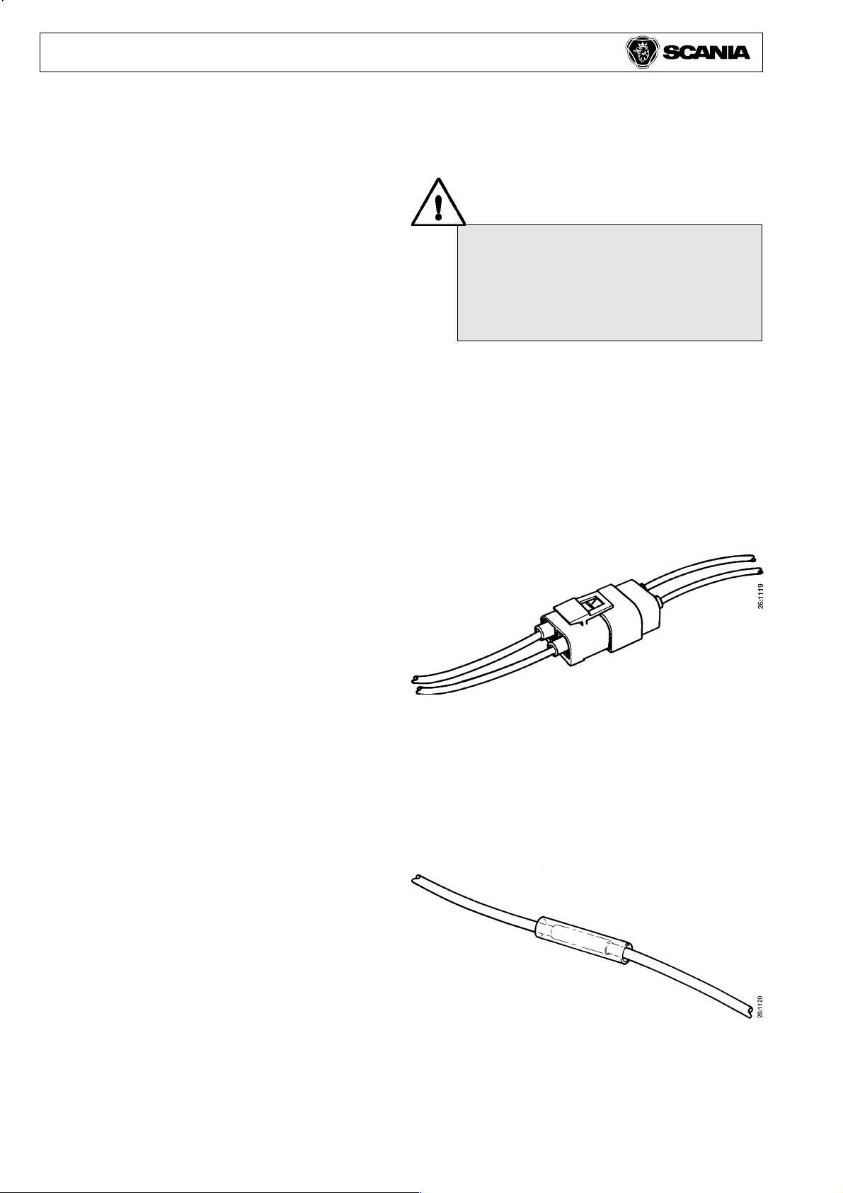
Many connectors have a double latching
mechanism for cable terminals.
It is important to release or secure the
double latching mechanism after
changing or adding connectors.
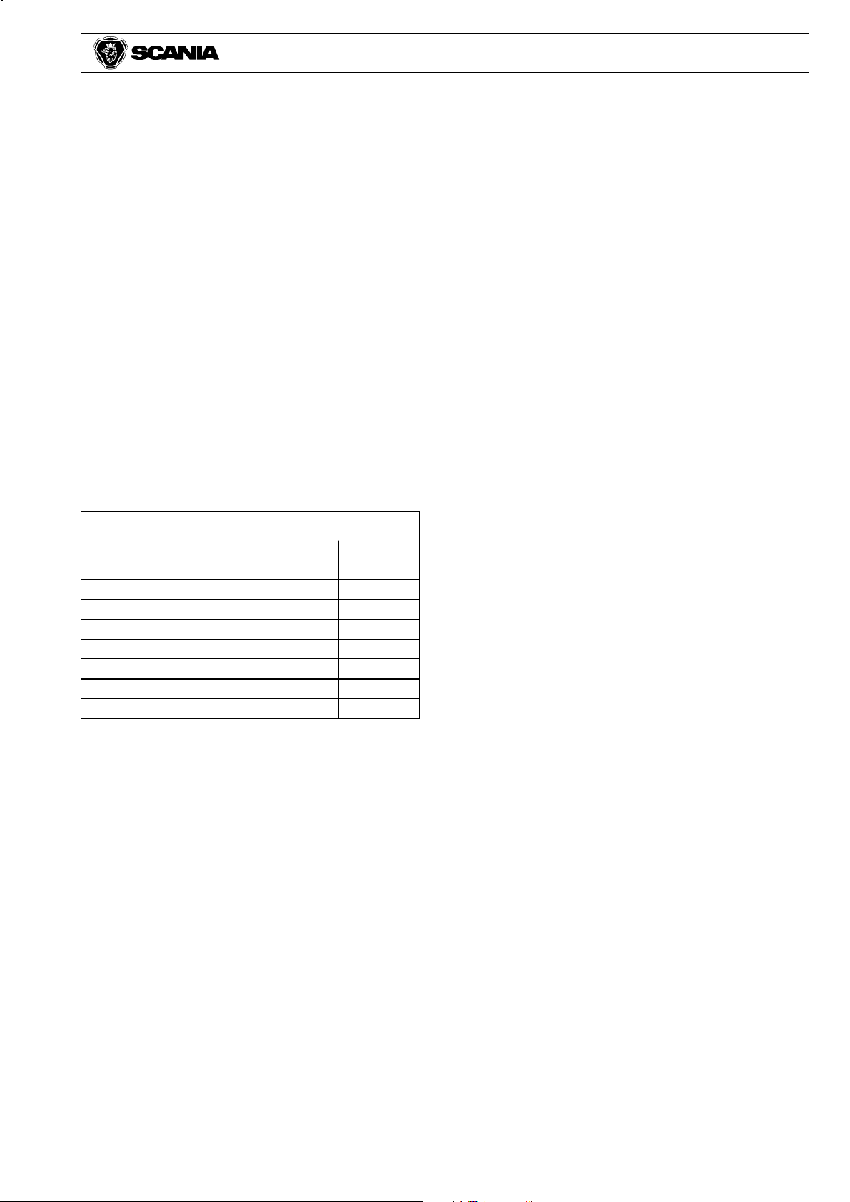
Splice connector
Use splice connector part No. 341333 for splicing
cable 1-2.6 mm2. This is wound with vulcanising
tape part No. 380128 and cover tape part No.
380129.
Alternatively, use a splice connector with adhesive
lined heat shrink tubing.
Part No. 1112499 0.75 mm
1112500 2.5 mm
1112501 3-6 mm
4
2
2
2
© Scania CV AB 2003
Page 5
POWER CONSUMPTION
Batteries, alternator and current consumption must be
matched to each other. There should be a charging
equilibrium.
Alternator capacity should be matched to current
consumption so that battery damage is avoided.
The time aspect is important. The current taken from
the batteries must restored within a day or two.
What is the driving cycle like? Frequent starting and
lengthy idling periods will not charge up the batteries
as efficiently as long-haul runs. The alternator generates less current at low engine speeds.
Some examples are given below.
Electrical system 11
Engine speed
(rpm)
500 30 42
600 40 58
700 46 68
800 50 76
1000 56 82
1200 60 88
1600 64 92
Temperature is also important. A battery is much
less able to accept a charge at low temperatures. To
achieve charging balance the alternator should have
an overcapacity of about 15-25 A. In general, it
could be said that an overcapacity of about 15 A
suffices for a vehicle driven over long distances
without stopping (e.g. long-haul runs) while an
overcapacity of about 25 A is needed for a vehicle
making frequent stops (e.g. a delivery van).
Alternator
65A
(A)
90A
(A)
To check whether the alternator has sufficient
capacity, obtain the total current consumption using
the tables below and then add the overcapacity.
Note that this is a very approximate calculation.
© Scania CV AB 2003
5
Page 6
Electrical system 11
To avoid shortening the useful life of the batteries,
the radio position on the ignition switch should be
used whenever possible for supplying power. In the
drive position the entire electrical system is
engaged, which increases current consumption and
with it a bigger drain on the battery.
Normal power consumption, truck
Electric fuel injection 1 x 5 A = 5 A
Main beam headlights 2 x 3 A = 6 A
Rear lights 4 x 0.25 A = 2 A
Front position lights 2 x 0.25 A = 0.5 A
Width marker lights 2 x 0.25 A = 0.5 A
Instrument illumination 20-30 x 0.05 A = 1.5 A
Fan motor 1 x 5 A = 5 A
Windscreen wipers 1 x 4 A = 4 A
Air dryer 1 x 3 A = 3 A
Radio ( std ) 1 x 2 A = 2 A
Normal power consumption, trailer
Rear lights 4 x 0.5 A = 2 A
Side marker lights 8 x 0.5 A = 4 A
Width marker lights 2 x 0.25 A = 0.5 A
Box interior lighting 4 x 2 A = 8 A
Guide values for extra equipment
Operating
time
Extra lights 2-4 x 3 A = 6-12 A 50%
Side marker lights 4-6 x 0.5 A = 2-3 A 100%
Roof lighting, external 1 x 4 A = 4 A 50%
Loading lights 2 x 4 A = 8 A 50%
Electrically-heated seats 2 x 2.5 A = 5 A 25%
Electrically-heated mirrors 2 x 2 A = 4 A 25%
Refrigerator 1 x 2 A = 2 A 60%
Extra cab heaters: 25%
a) Engine cab heater (Webasto) = 6 A
b) Cab heater (Eberspächer) = 3 A
c) Short stop heater = 4 A
Retarder (Electric) 1 x 100-200 A = 100-200 A 5-10 %
Battery heater 1 x 10 A = 10 A 25-50 %
Tail lift 1 x 100 A = 100 A ----
6
© Scania CV AB 2003
Page 7
SIZING FUSES AND CABLES AND VOLTAGE LOSS
Calculate how many amps are consumed when
extra equipment is connected in order to size the
fuses and cables.
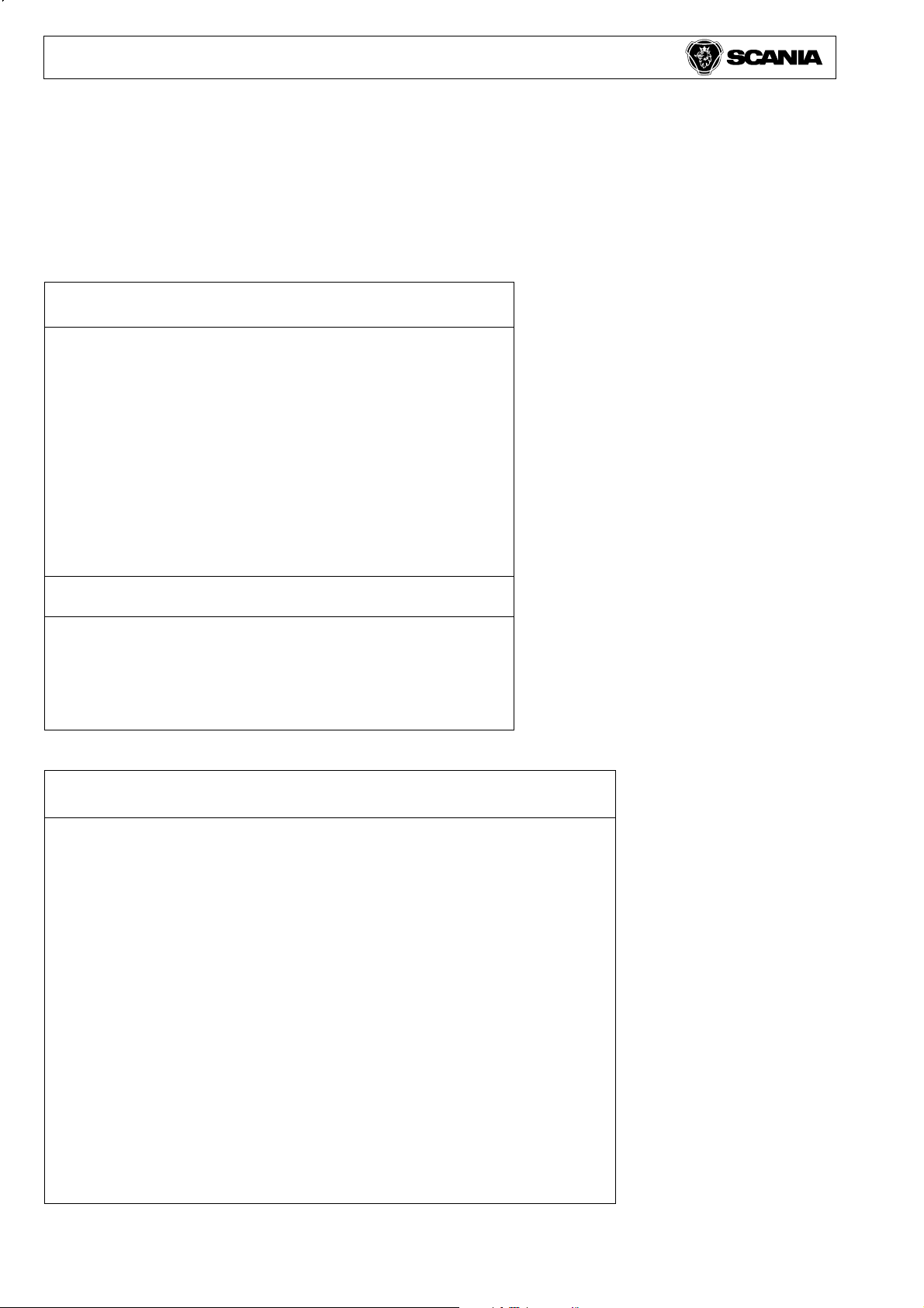
Use the following equation:
I = P/U
I = Current in amps (A)
P = Power in watts (W)
U = Voltage (V)
If two of P, U and I are known, the third can be
calculated as follows:
Electrical system 11
U = P/I, I = P/U, P = U x I
Example
Power P = 200 W
Voltage U = 24 V
I = 200 W / 24 V = 8.3 A
The calculated total current through a fuse should
not exceed 60 % of the amp rating.
Sizing cables
Current, power and the distance to the load
determine the cross-section of the conductor.
Current Power Cross-section
10 A 200W 0.75-1 mm
15 A 400W 1.5 mm
20 A 500W 2.5 mm
25 A 650W 4.0 mm
40 A 850W 6.0 mm
50 A 1200W 10.0 mm
2
2
2
2
2
2
Always use the correct fuse. An
oversized fuse can cause fire in the
electrical system.
If cables are long, it may be necessary to use a
thicker cable to reduce voltage loss.
Normally, a voltage loss of 5 % (1.2 V) is acceptable.
Voltage loss in copper conductors is calculated
using the following formula:
U = I x (0.0175 x L) / A
Cables outside the cab should be at least 1.5 mm
2
These values are based on the heat generated in the
cable with continuous current.
© Scania CV AB 2003
U = Voltage loss (V).
I = Current in amps (A).
L = Length of cable.
A = Cross-section of conductor (mm2).
7
Page 8
Electrical system 11
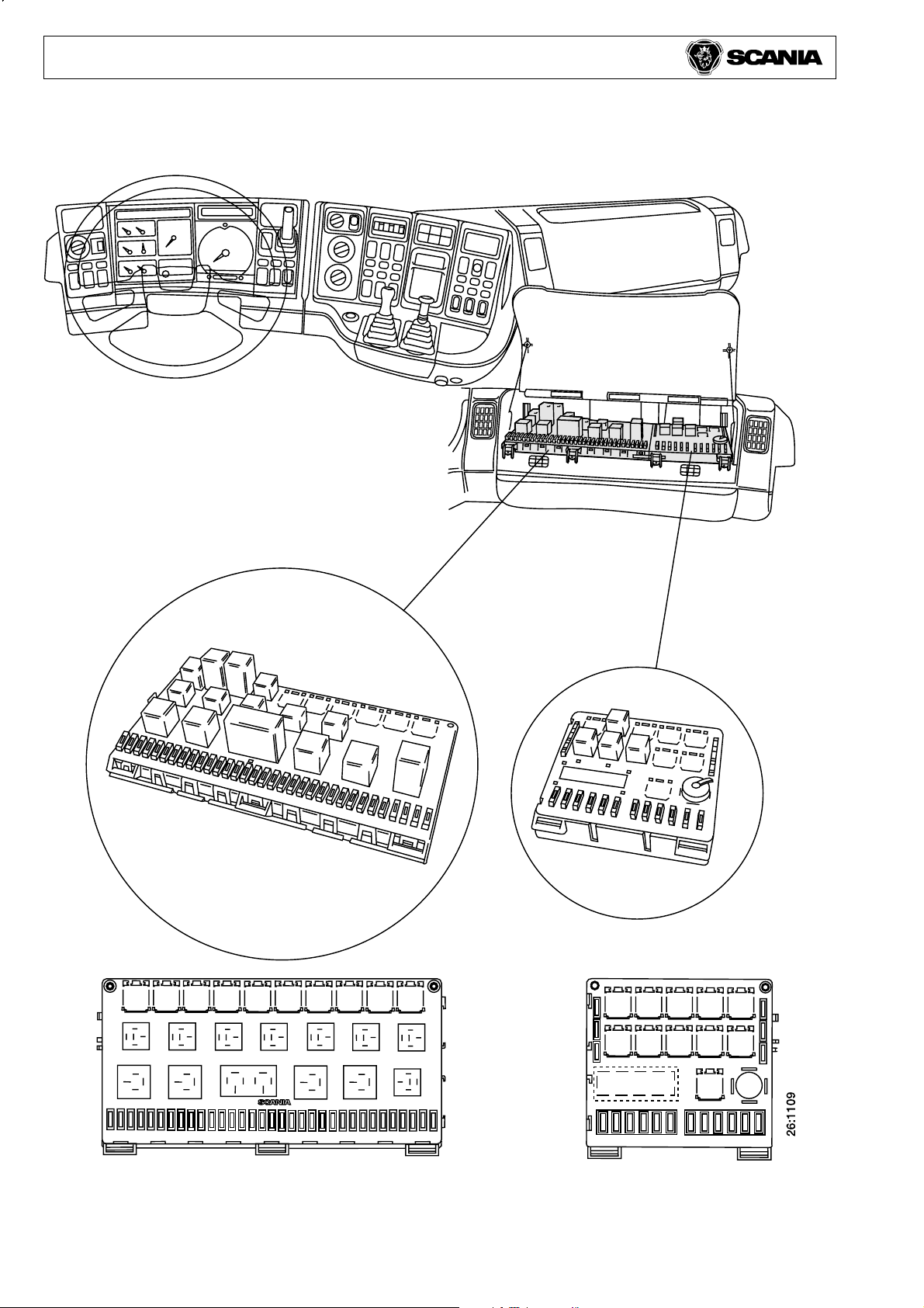
CENTRAL ELECTRIC UNIT
Central electric unit Extra central electric unit
(accessories/bodywork)
8
© Scania CV AB 2003
Page 9
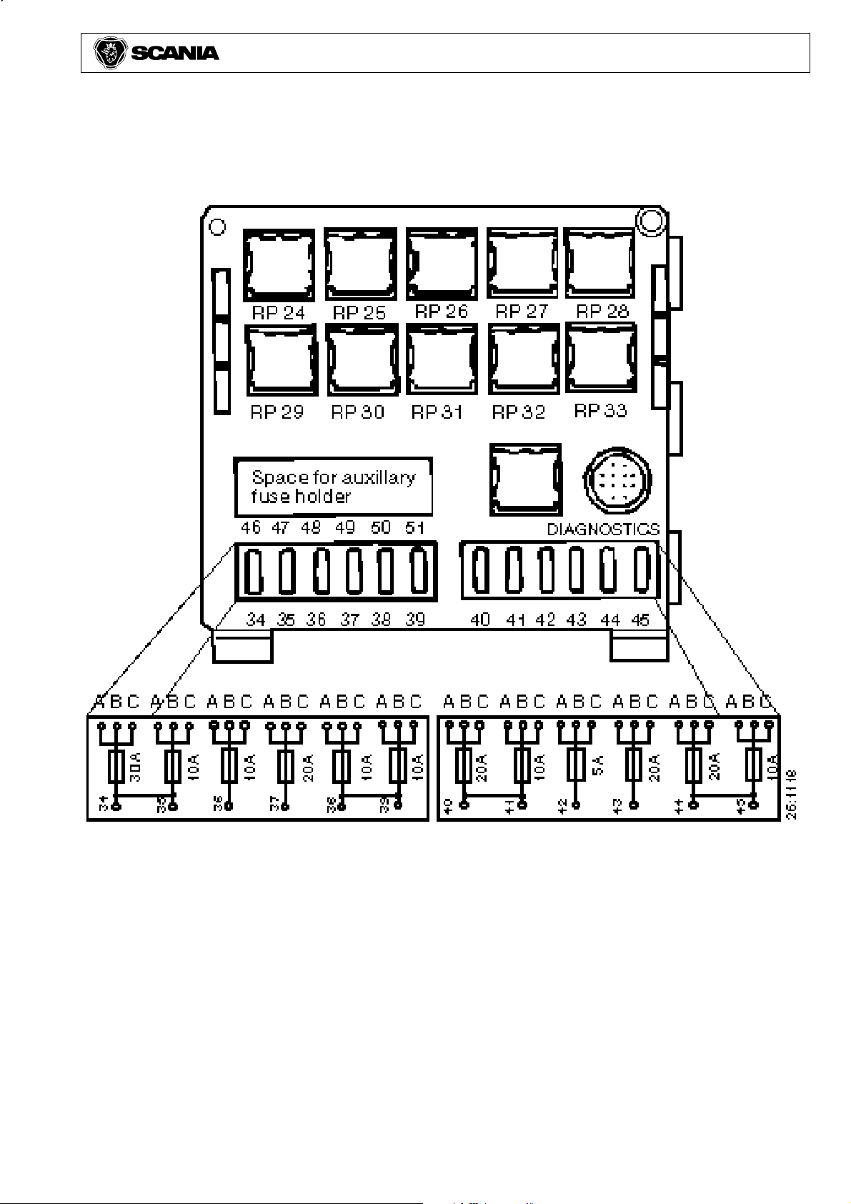
Extra central electric unit (accessories/bodywork)
Electrical system 11
The extra central electric unit can have a varying
number of positions occupied from factory,
depending on what extra equipment, such as fuel/
battery heater and flame start, is fitted.
Extra fuse holder for positions 46-51, part number
1320852.
Extra relay holder, 9-pole, part number 1320851.
© Scania CV AB 2003
9
Page 10
Electrical system 11
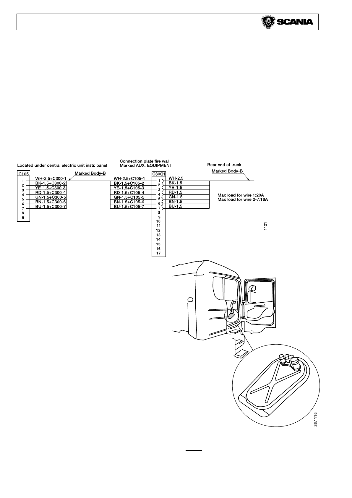
FACTORY-FITTED WIRING
With the exception of tractors, all vehicles can be
ordered with a seven-core cable running from the
cab to the rear end of the frame. Via a connector in
the bulkhead marked C300 this cable is wired to a
white connector marked C105 located under the
central electric unit and terminates without a
connector about 1 metre behind the junction box at
the rear end of the frame.
The cable is of ADR design on vehicles ordered
with ADR.
Cable cross- Colour Max. load
section area
1 2.5 mm
2 1.5 mm
3 1.5 mm
4 1.5 mm
5 1.5 mm
6 1.5 mm
7 1.5 mm
2
2
2
2
2
2
2
white 20 A
black 16 A
yellow 16 A
red 16 A
green 16 A
brown 16 A
blue 16 A
Suitable connector housing for C105: part. no. 813556
Suitable round female terminals
Cable cross-section: 1.5 mm
Cable cross-section: 2.5 mm
2
part no. 813925
2
part no. 813927
If the 7-core cable is not enough, or if it is
necessary to route cables to the cab of tractor units,
there are four lead-throughs of varying diameter in
the floor on the passenger side.
Cable lead-throughs
Note: The floor panel is illustrated upside
down to show the rubber plugs.
10
© Scania CV AB 2003
Page 11

Factory-fitted wiring in cab
It is important to consider what optional wiring is required before ordering the
truck as it is complicated to add wiring in the cab, especially in the roof.
All cabs are fitted with prerouted cables for connection of the following
equipment:
- High-mounted working lights on rear wall.
- Rotating beacon mounted either on the rear wall or roof
(Topline only on rear wall).
- Sign lighting.
- Spotlights under exterior sun visor.
- Electric sunroof.
- Interior background lighting.
- FM/AM radio.
- Electrically adjustable rear-view mirrors.
Electrical system 11
For most of the above equipment all connections are made in the roof shelf switch
panel with the exception of external parts of the equipment.
However, in the case of the FM/AM radio, the roof shelf and some trim must be
removed and modified. Fitting is made considerably easier with the radio
prewiring option (see below).
In the case of the electrically adjustable rear-view mirrors, only the cable
harnesses between the cab and doors contain the cables for this equipment.
Mounting is much easier with the pre-wiring option for electrically adjustable
rearview mirrors (see below).
The following optional equipment is also available for all cabs from factory:
- Fully fitted sign lighting.
- Fully fitted spotlights (2) in exterior sun visor.
- Fully fitted spotlights/foglights (2) in the bumper.
- Fully fitted electric sunroof.
- Fully fitted interior background lighting.
- Wiring for FM/AM radio, 12 V.
- Fully fitted FM/AM radio, 12 V.
- Fully fitted Scania Alert. (Only in combination with radio wiring or fully fitted
FM/AM radio).
- Wiring for CB radio.
- Wiring for cell phone.
- Wiring for electrically adjustable rear-view mirrors (enables fitting of
electrically adjustable mirrors on both driver and passenger sides).
- Fully fitted electrically adjustable rear-view mirror on passenger side.
- Electrics for front mounted equipment
© Scania CV AB 2003
11
Page 12

Electrical system 11
Seven holes for electrical equipment are predrilled in
the roof panel.
1. An aerial is fitted for the radio or radio prewiring
options. If neither option has been selected the hole
is plugged but an aerial cable is fitted between the
hole and the radio outlet in the roof shelf.
2. Cable grommet and cables for upper position
marker lights. A connector housing for fitting upper
spotlights is available for connection behind the
cable grommet. Wiring is available as a spare part.
3. An aerial cable for the roof shelf is fitted behind
the rubber plug if the prewiring for CB radio option
is selected.
4. Hole with rubber plug.
5. Wiring behind rubber plug for rotating beacon and
work lighting. Three-core cable (common earth
lead)
6. Wiring behind rubber plug for sign lighting and
rotating beacon. (Not Topline.)
7. If the mobile telephone prewiring option is
selected, an aerial bracket with connected cable
which ends in the dashboard is fitted, rolled up at
the A pillar on the drivers side.
Note: The drawing is in mirror image for right-hand
drive trucks.
12
© Scania CV AB 2003
Page 13

Electrical system 11
Factory-fitted wiring for FM/AM radio
Cable harness for radio equipment, radio bracket, radio panel and 24/12V-4A
voltage converter fitted in the roof shelf. Radio aerial mounted on roof panel,
including factory-fitted 75-ohm impedance aerial cable connected to the radio
outlet in the roof shelf.
Fitted speakers, each with 4-ohm impedance, nominal 30 W and maximum 40 W
output, as follows:
Normal sleeper cabs: Three speakers fitted in the roof shelf.
Topline: Total of four speakers, two fitted in the roof shelf and one in each rear
corner panel.
Factory-fitted wiring for CB radio
One extra radio bracket, extra voltage converter 24/12 V as below and prerouted
12 V cables are fitted in the roof shelf above the windscreen.
Prerouted aerial cable, impedance 50 ohm, between the plug in the roof and the
roof shelf. One extra speaker, impedance 4 ohm and max. output 20 W, fitted in
the centre of the roof shelf.
Factory-fitted wiring for cell phone
An extra 24/12V voltage converter as below, mounted in the roof shelf.
A 12 V socket visible mounted in the roof shelf switch panel.
A bracket with a 12 V socket fitted in the inner side panel under the bunk on the
passenger side.
An aerial bracket on the cab roof with connected aerial cable which ends in the
dashboard, rolled up at the A pillar on the drivers side.
Factory-fitted extra voltage converter 24/12 V
The extra voltage converter is mounted in the roof shelf when the prewiring
option is selected for either CB radio, mobile telephone or both.
The voltage converter, which is connected directly to the battery and not
controlled by the ignition switch, can be loaded with 12V-15A, i.e. 200 W.
Factory-fitted wiring for electrically operated rear-view mirrors
Cable harness fitted in the instrument panel, to the central electric unit and to both
door bridge cables.
Prewiring makes it easy to add electrically adjustable mirrors, either only on the
passenger side or on both sides.
© Scania CV AB 2003
13
Page 14

Electrical system 11
Connecting extra lights
Extra lights can not be connected directly to the light
switch but must be controlled from an output on the
main beam relay.
See attachment Manual: Wiring diagram.
Power socket in cab
A 12 V and a 24 V socket are normally located in the
dashboard on the passenger side. Versions with two
24 V sockets also occur.
With the mobile telephone prewiring option selected,
two 12 V sockets are fitted additionally.
(See under prewiring for mobile telephone.)
Extra direction indicators
The flasher relay, see attachment Manual: Wiring
diagram, has three circuits - vehicle front/side,
vehicle rear/side and trailer, with protection against
overloading and a warning function for bulb filament
failure.
When a lamp blows, the driver is warned as below.
The indicator lamp goes out if:
- A lamp at the front has blown
- The last lamp at the rear has blown
The indicator lamp for the trailer goes out if the last
lamp on the trailer blows.
Note: The system must not be loaded with more than:
eight 21 W bulbs on each side of the vehicle.
Three lamps are factory fitted. For bodywork there is
capacity for two lamps in the rear/side circuit and
three lamps in the trailer circuit.
If more or stronger lamps are connected, the overload
protection activates when the hazard lights are
switched on and they stop flashing.
The overload protection is reset by turning the starter
switch to 0.
Extra brake light lamps
The brake light circuit must not be loaded with more
than eight 21 W lamps.
If the circuit is overloaded, the life of the brake light
relay is reduced.
See attachment Manual: Wiring diagram.
FLASHER RELAY 24V
2+1....3+1....3x21W
9 L 31 30 30 15 R RT
LT L 31 30 30 15 R RT
LA LF C HWL HW C2 RF BR
1234567 8
1122
14
© Scania CV AB 2003
Page 15

Electrical items for front-mounted equipment
Vehicles prepared for front-mounted equipment can,
in addition to brackets (see section Equipment
mounted at the front in Chapter 7 Other bodywork
equipment) also be prepared with electrical items
such as switches and cable harnesses.
This electrical preparation consists of three parts:
1. Switch for plough lights on instrument panel.
The switch is marked S65 and fitted in the upper
part of panel E, see attachment Manual: Wiring
diagram, on vehicles without pressure gauge for
axle weight and in the lower part on vehicles with
pressure gauge.
Part numher of the switch is 1391312.
Part number of the switch decal is 1390521.
Electrical system 11
2. Wiring harness in the instrument panel.
The wiring harness is fitted from switch S65 to the
central electric unit. Part number of the wiring
harness is 1391313.
3. Wiring harness from central electric unit to underside of service panel.
Trucks with P and R cabs have four contacts fitted
behind the service panel.
On trucks with T-cab those contacts are to be found
under the service step on the passenger side. The
contacts are marked C364, C365, C366 and C367.
They contain the following signals:
C364 - Signals for main beam, dipped beam, position
light and direction indicators on the left side.
C365 - Signals for main beam, dipped beam, position
light and directon indicators on the right side.
C366 - Signals for position light on front-mounted
equipment, left side.
C367 - Signals for position light on front-mounted
equipment, right side.
There are also four sealing plugs to use whenever the
contacts are not in use. These plugs should always be
used to prevent the contacts from corrosion.
© Scania CV AB 2003
15
Page 16

Electrical system 11
Suitable contacts to use for connection to C364 and
C365 are:
Part number 815641 - Socket (male)
815635 - Socket (female)
Suitable contacts to use for connection to C366 and
C367 are:
Part number 815638 - Socket (male)
815632 - Socket (female)
Other parts:
Part number
815840 Cable connector type casing (7 per
contact)
815838 Cable connector type pin (7 per contact)
1354883 Both for C364 and C365 (cable diameter
4,2-6,5 mm)
1354885 Both for C364 and C365 (cable diameter
6,2-9 mm)
814776 Both for C366 and C367 (cable diameter
4,2-6,5 mm)
815832 Both for C366 and C367 (cable diameter
6,2-9 mm)
Vehicles with front-mounted equipment may also need
extra switches and joysticks for manoeuvring.
A panel equipped with two extra switches and two
joysticks is obtainable ex works or can be purchased
as an accessory. This panel screws onto the regular
instrument panel below the parking brake lever.
Part number Part name Quantity
1384610 Switch panel 1
1113490 Joystick (4-way) 2
1390308 Mounting frame 1
1371214 Switch 2
815161 Screw 4
1115794 Decal set 1
16
© Scania CV AB 2003
Page 17

EXTRA CONTROL BOX
An extra control box fitted to the rear of the vehicle can be useful
when handling loads (vehicle with air suspension).
Connection between connectors C78 and C163 is the most suitable.
C78 is located below the central electric unit. See attachment
Manual: Wiring diagram. Use a cable cross-section of 0.75 mm2.
Also fit a two-way switch as shown in the illustration.
Electrical system 11
C78
1
2
3
4
C78
1 Red
2 Black
3 Yellow
4 Green
15L
31
ELC 20
ELC
21
C163
1
2
3
4
A
1 Control box
2 Extra control box
A Two-way switch
1
2
3
1
M
2
M
P
O
T
4
S
1
1
M
2
M
P
O
T
S
105 893
2
© Scania CV AB 2003
17
Page 18

Electrical system 11
JUNCTION BOX IN FRAME
The junction box at the rear of the frame is located
either on the last crossmember or on the frame
web, depending on the type of vehicle.
Left-hand rear light is connected to positions
1, 2, 3, 4, 6.
Right-hand rear light is connected to positions
1, 2, 3, 5, 7.
Side marker lights are connected to positions 4, 5.
Trailer cable 24S is connected to positions 1, 2.
Trailer cable 24N is connected to positions
3, 4, 5, 8, 9, 10.
Differential lock is connected to positions 11, 12.
See also chapter 14 Bodywork adaptations BWA
section Trailer connections.
18
© Scania CV AB 2003
Page 19

PLACE FOR OPTIONAL ELECTRICAL ACCESSORIES IN TOPLINE CAB
Our Topline cabs have two storage compartments on
the rear wall and one compartment on each side wall.
Electrical system 11
If you wish to use one or more of these spaces to fit
a TV, microwave, CD changer etc., the hatch must
be removed.
The rear part of the compartment is left in position
to protect the cab insulation.
In order to fit extra equipment, a frame must be
manufactured which uses the four screws securing
the compartment.
There is a space above compartment A which can
be used for a small TV or CD changer.
When making the frame for this space, use the top
two screws in compartment A and the bracket just
above on the roof.
When compartments B-C are used, standing space
in the cab is limited with the upper bunk folded
out.
Good ventilation round optional accessories is
essential due to the risk of fire. Exercise care
when clamping wiring harnesses and always use
rubber grommets at lead-throughs.
All extra equipment in these spaces
must be fitted so that it cannot become
detached in an accident.
© Scania CV AB 2003
19
Page 20

Electrical system 11
POWER TAKE-OFFS IN COMBINATION WITH OPTICRUISE
The Opticruise is programmed to engage and
disengage gears at the torque level which is best for
the gearbox.
If power take-offs, or other equipment, which can
be engaged and disengaged during operation and
which increase torque considerably more than
normal wear, are coupled, the Opticruise must
receive a signal in order to compensate for the
increased torque.
The Opticruise control unit has two different inputs
to handle different types of power take-off / load.
The inputs are active at +24 V.
THE INPUTS MUST ONLY BE ACTIVE
WHEN THE LOAD IS COUPLED.
EK/ED Power take-off
This input, pin 9 on the control unit, must be used
for engine-driven (independent of clutch) power
take-offs. The Opticruise can compensate for an
extra torque take-off of maximum 200 Nm during
operation.
Torque compensation can only be made for one
power take-off or one extra load.
Prewired connections
EK / ED
The cable between S31 and the control unit is
always fitted. If EK / ED is opted for, it is
connected to the base for S31. Otherwise, it is not
connected.
The cable between the power take-off and S31 is
only fitted if the power take-off has been opted for.
EG
Both cables are fitted as standard and the cable to
S30 is connected.
EG Power take-off
This input, pin 50 on the control unit, must be used
for gearbox-driven (independent of clutch) powertake offs.
With this input activated, it is not possible to
change gear while driving. Changing gear with the
power take-off engaged can damage the gearbox.
However, it is possible to engage a gear when the
vehicle is stationary in order to allow range operation with the power take-off active.
Several power take-offs or other equipment which
require gear locking can use this input. However,
when several signals are connected at the same
time, they must be connected so that no conflict
arises with potential differences.
20
© Scania CV AB 2003
Page 21

EDC
Electrical system 11
Trucks equipped with EDC (Electronic Diesel
Control) have a number of prewired functions to
facilitate crane operation and the like.
The prewired functions are:
- Hand throttle
- Limited hand throttle
- Raised idling speed
- Fixed engine speed
- Torque limitation
- Speed limiter (vehicles with coordinator)
- Engine stop
- External control of engine speed
The connections are made at the factory and cables are
routed to a 5-pin connector marked C107 under the
central electric unit.
On vehicles with a coordinator the connector is of 6pin type and labelled C271. It has the same location
under the central electric unit and both connectors are
blue. In both cases the housings are complete
assemblies with corresponding connectors ex works.
- Cable terminal for C107, part no. 199950
- Cable terminal for C271, part no. 815886
1 Control unit (may be located elsewhere)
2 Throttle pedal sensor
3 Brake pedal switches
4 Clutch pedal switch
5 Control for cruise control
6 Tachograph (speed)
7 Diagnostics switch with lamp
8 Indicator lamp
9 Power supply relay
10 Diagnostics socket for PC
The functions are engaged by earthing
different combinations of certain pins on
the connector.
Use a cable cross-section area of 0.75 mm2.
1 Violet
2Grey
3 Brown
4 Green
5 White
6 Yellow (only C271)
© Scania CV AB 2003
21
Page 22

Electrical system 11
Hand throttle (normal)
The hand throttle is used to set the desired engine
speed during crane operation and the like. Setting is
carried out using the cruise control switches. The hand
throttle can be used when the vehicle is stationary or
when driving at low speeds, max. 10 km/h.
Engine speed can be set anywhere between 500 and
2000 rpm.
See vehicle Operators manual.
Limited hand throttle
The limited hand throttle basically works in the same
way as the normal hand throttle. The difference is that
engine speed (between 700 and 2000 rpm) and torque
(between 200 Nm and maximum) can be limited to
protect equipment connected to the power take-off.
It is also possible to select whether the throttle pedal
is to be active or disengaged. These options are
programmed by the Scania workshop. The desired
engine speed, up to the programmed rpm, is set with
the cruise control switches. The function is activated
by earthing connector pin 1.
See also vehicle Operators manual.
22
© Scania CV AB 2003
Page 23

Raised idling speed
Minimum engine rpm can be selected using the
raised idling speed function. Idling speed can be
increased in this way for such purposes as filling
the compressed air system or warming up the
engine. The function is also useful on vehicles with
a cement mixer.
Engine speed (500-800 rpm) is set with the cruise
control switches and is not disengaged by
activating the brake pedal, clutch pedal, exhaust
brake or retarder. The set engine speed can be
stored in the memory.
The function is activated by earthing pin 5.
See also vehicle Operators manual.
Fixed engine speed
Fixed engine speed means that the driver cannot
alter engine speed with either the throttle pedal or
the cruise control switches. This can be used when
precision is important.
Engine speed (600-2000 rpm) and maximum
torque (200-2000 Nm) are programmed by the
Scania workshop.
The function is activated by earthing pins 1 and 5.
See also vehicle Operators manual.
Electrical system 11
© Scania CV AB 2003
23
Page 24

Electrical system 11
Example of setting three fixed engine speeds
Certain types of bodywork equipment require one or
more different engine speed levels.
Examples showing how up to three different fixed
engine speeds can be set are given below.
The cruise control switch must be in the ON position
for these settings to function correctly.
Engine speed 1
Setting engine speed 1, say 750 rpm, using the
Raised idling speed function.
This function can be used between 500 and 800 rpm.
Engine speed 2
Setting engine speed 2, say 1100 rpm, using the
Limited hand throttle function.
This function can be used between 700 and 2000 rpm.
Engine speed 3
Setting engine speed 3, say 1400 rpm, using the
Fixed engine speed function.
This function can be used between 600 and 2000 rpm.
Engine speed settings 1 and 2 can be set/adjusted by
the driver using the cruise control switches. See
vehicle Operators Manual.
Engine speed setting 3 is to be programmed at a
Scania workshop.
24
© Scania CV AB 2003
Page 25

Torque limitation
The EDC unit can be programmed for three different levels of torque limitation. These are chosen
by earthing pins 3 and 4 in different combinations.
The function can be combined with engine speed
control.
Torque limitation 1
With Torque limitation 1 engaged the engines
torque curve is peaky. It then feels as though
pulling power increases when engine speed drops,
e.g. on uphill gradients.
The function is activated by earthing pin 4.
Torque limitation 2
With Torque limitation 2 engaged the torque is
limited to 700 Nm at engine speeds up to
1000rpm. At higher engine speeds the torque limit
is slightly lower.
Electrical system 11
Nm
107 461
r/min
Nm
The function is used on vehicles with a torque
converter and manual gearbox. Engagement can be
arranged so that the function is active when the
clutch pedal is depressed. That is to protect the
clutch from overheating, such as when pulling
heavy loads.
The function is activated by earthing pin 3.
Torque limitation 3
With Torque limitation 3 a torque curve with early
breakaway is obtained. Torque limitation starts at
1000 rpm and stops at 1400 rpm. This function can
be used as an alternative to the engine speed
control function Limited hand throttle to protect
a power take-off, for instance.
With this function it is also possible to reprogram
the torque curve to suit your own requirements.
This is done at a Scania workshop.
The function is activated by earthing pins 3 and 4.
107 387
r/min
Nm
107 388
r/min
© Scania CV AB 2003
25
Page 26

Electrical system 11
Speed limiter
Vehicles having the 6-pin connector C271 also
have an additional function, speed limitation. This
can be used for example on refuse collection trucks
with an external platform and can be engaged when
someone is standing on the platform. The speed
limiting function is independent of the regular
cruise control and can be used as a complementary
system to it.
The default speed is 70km/h but it can be changed
at a Scania workshop. The function is activated by
earthing pin 6.
This function is also included on vehicles with unit
injectors (PDE) and EDCMS6. The function is then
activated by applying current (+24 V) to pin H-6 of
connector C112 at the cab lead-through.
See attachment Manual: Wiring diagram.
Cable terminal for C112.
Part no. 815 844
Use a cable cross-section area of 0.75 mm2.
You can see whether or not the vehicle has a
coordinator by looking at the diagnostics panel. If it
does have a coordinator there will be a switch as
shown in the illustration. In addition, the switch
lamp comes on for a few seconds when power is
turned on with the ignition switch.
Engine stop
With the engine stop function the engine can be
stopped quickly if, for instance, an accident occurs
during crane operation.
When the engine stop button is pressed, pin 2 of
connector C107/271 is earthed and the engine
immediately stops if the vehicle is stationary. If the
stop is activated while the vehicle is in motion,
engine speed drops to idling but the engine is not
shut down. This is in order to retain servo
assistance for power steering.
26
© Scania CV AB 2003
Page 27

External control of engine speed
General
The speed of EDC engines can be regulated with the
cruise control. It can be operated from outside the
vehicle with an extra control unit connected to the
vehicle by an extension cable. The connection below
ensures that external control of engine speed is only
possible when the parking brake is applied.
Connection of the extra control unit is shown in
wiring diagram no. 16:04-57, part number 1 712 468,
which can be ordered from your Scania dealer.
Proceed as follows
1. Connection of the extra control unit is via pins 8
and 9 of connector C23 (a 9-pin connector located
on the cable nearest the cruise control switch
assembly).
Electrical system 11
2. Connect an extra cable to pin 9 which leads to a
new connector for the extra control unit. This
should be located in the front cab wall.
3. Transfer the existing cable connected to pin 8 of
connector C 23 to pin 30 of a new relay (part no.
1 391 322) mounted in the central electric unit.
4. Run a new cable from pin 8 of connector C 23 to
pin 87A of the relay and a cable from pin 87 of the
relay to the new connector for the external control
unit.
5. Power for the new relay is supplied via fuse, as
shown in the wiring diagram, with switch (part no.
1 488 066) and a cable to connector C 56 (under
the central electric unit), terminal block R pin 3
(signal when the parking brake is applied).
6. The external control unit must be arranged
according to the schematic so that only one
function at a time can be activated. The tolerance
of the resistors should be ±1%.
7. The external control units connection cable should
be twisted with 30-40 turns per metre to avoid
electrical interference in the system.
8. A motor stop should be mounted adjacent to the
external control unit.
© Scania CV AB 2003
27
Page 28

Electrical system 11
ADR
Scania supplies chassis equipped in conformity
with applicable international ADR regulations.
The chassis are supplied with equipment and
certification for the relevant ADR category (AT,
EXII, EXIII, FL and OX), which means that no
modification of ADR related components/systems
shall be made to the chassis in connection with
bodywork assembly unless so required by national
laws and regulations.
Bodywork on ADR-equipped vehicle
The following applies to the connection of extra
equipment on an ADR classified chassis:
- All bodywork/modification affecting ADR must
be approved by the vehicle inspection authority
in the country of registration.
- Conversion of a non-ADR chassis may be
carried out in consultation with a Scania
distributor and the relevant national authority.
To facilitate official approval the use of genuine
Scania ADR parts is recommended.
- An ADR-classified cable is available for the
electrical connection of bodywork. See the
section entitled Factory-fitted wiring in this
chapter.
- The workshop or bodywork builder is
responsible for ensuring that bodywork/
modification complies with ADR requirements.
28
© Scania CV AB 2003
Page 29

SWITCHES
Tag axle lift (air suspension) 353623 Interior lighting 353625
Electrical system 11
Electric sunroof 353628
Socket 353642
Power take-off (dependent on parking brake)
353638
Short stop heater, Central lock
(Topline from upper bunk)
353646
Interior lighting (Topline),
Air horn 383744
© Scania CV AB 2003
Robson drive 1115426
29
Page 30

Electrical system 11
Retarder 1350317TC 1347592
Rheostat (light level) 1350547
Speed limiter with cruise control
1357244
Front foglight 1352114
Opticruise (selection of driving mode)
1357375
30
Mechanical air suspension
1367546
Rheostat (instrument illumination)
1371210
© Scania CV AB 2003
Page 31

Electrical system 11
Differential lock (all wheel drive) 1371213
Instrument panel
1371215
Differential lock / Power take-off 1488071
Instrument panel
1371216
Tag axle lift (leaf spring) 1405631
Rear foglight, Scania Alert,
High-level work lights on rear wall 1488067
© Scania CV AB 2003
Electric windows 1413146
Electrically heated rear-view mirror, Sign lighting,
Interior background lighting, Spotlights, Rotating
beacon 1488066
31
Page 32

Electrical system 11
4x4/6x6 with ABS
1488070
Electrically adjustable mirror on passenger side
1361023
Electrically adjustable mirrors for both driver
and passenger sides 1380910
32
© Scania CV AB 2003
 Loading...