

Sauter Italia S.p.A.
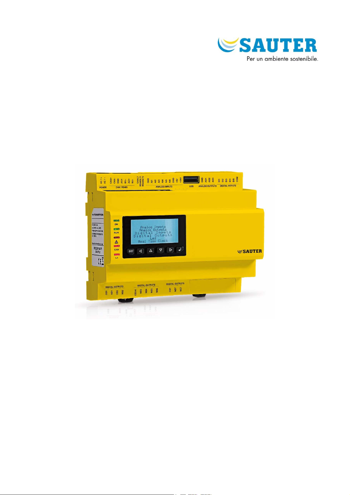
RDT 921 F901
Configurable controllers
RDT921F901 | Hardware manual ver. 1.0 | Code 114RDT921E104SAU
Hardware manual | ENGLISH
Code 114RDT921E104SAU
page 1 of 38

Sauter Italia S.p.A.
Important
Read this document thoroughly before installation and before
use of the device and follow all recommendations; keep this
document with the device for future consultation.
Only use the device in the way described in this document; do
not use the same as a safety device.
Disposal
The device must be disposed of in compliance with local
standards regarding the collection of electric and electronic
equipment.
RDT921F901 | Hardware manual ver. 1.0 | Code 114RDT921E104SAU
page 2 of 38

Sauter Italia S.p.A.
Index
1
1.1
2
2.1
3
3.1
3.2
3.3
4
4.1
4.2
4.3
4.4
4.5
4.6
4.7
4.8
4.9
5
5.1
5.2
6
6.1
6.2
6.3
7
7.1
INTRODUCTION ............................................... 5
Introduction .................................................... 5
DESCRIPTION ................................................. 6
Description ..................................................... 6
DIMENSIONS AND INSTALLATION ..................... 7
Dimensions: .................................................... 7
Installation...................................................... 7
Installation warnings ........................................ 8
ELECTRIC CONNECTION ................................... 9
Connectors ..................................................... 9
Meaning of connectors ...................................... 9
Insertion of the termination resistor of the CAN
CANBUS port ................................................. 13
Insertion of the RS-485 MODBUS master/slave
port termination resistor ................................. 13
Insertion of the RS-485 MODBUS slave port
termination resistor ........................................ 13
RS-485 MODBUS master/slave port polarisation 13
RS-485 MODBUS slave port polarisation ........... 13
Example of electric connection ......................... 14
Warnings for the electric connection ................. 14
USER INTERFACE ........................................... 15
Keypad ......................................................... 15
LED warning lights ......................................... 15
CONFIGURATION ........................................... 17
Configuration of a built-in LCD controller .......... 17
Configuration of a controller through a remote
user interface ................................................ 18
List of configuration parameters ...................... 20
TECHNICAL DATA .......................................... 31
Technical data ............................................... 31
RDT921F901 | Hardware manual ver. 1.0 | Code 114RDT921E104SAU
page 3 of 38

Sauter Italia S.p.A.
RDT921F901 | Hardware manual ver. 1.0 | Code 114RDT921E104SAU
page 4 of 38

Sauter Italia S.p.A.
RDT921F901 | Hardware manual ver. 1.0 | Code 114RDT921E104SAU
1 INTRODUCTION
1.1 Introduction
RDT900 is a range of configurable controllers for cooling and
air conditioning applications.
The controllers are equipped with a significant number of input
and output arrangements which make it possible to create a
flexible, modular and expandable network of control devices.
The range of available communication ports ( RS-485, CAN,
USB and Ethernet) and of supported communication protocols
promote the integration of the devices into larger systems.
For information on the use of the BACnet communication
protocol please consult the PICS.
The actual version implements a BACnet® standardized device
profile B-ASC, which doesn’t require the managing of
Scheduler and Calendar objects, instead required for the B-
AAC profile.
page 5 of 38
Sauter Italia S.p.A.
2 DESCRIPTION
2.1 Description
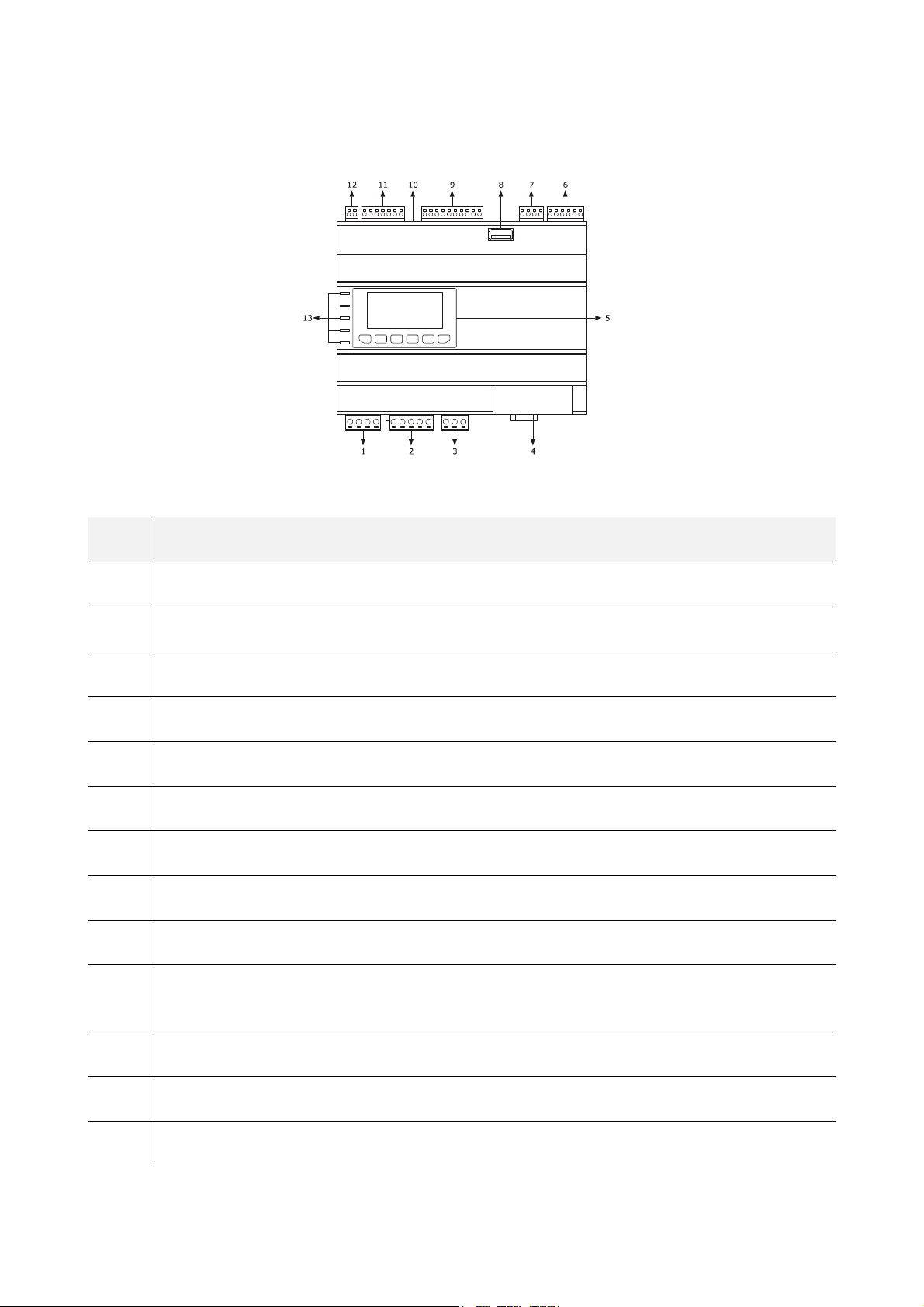
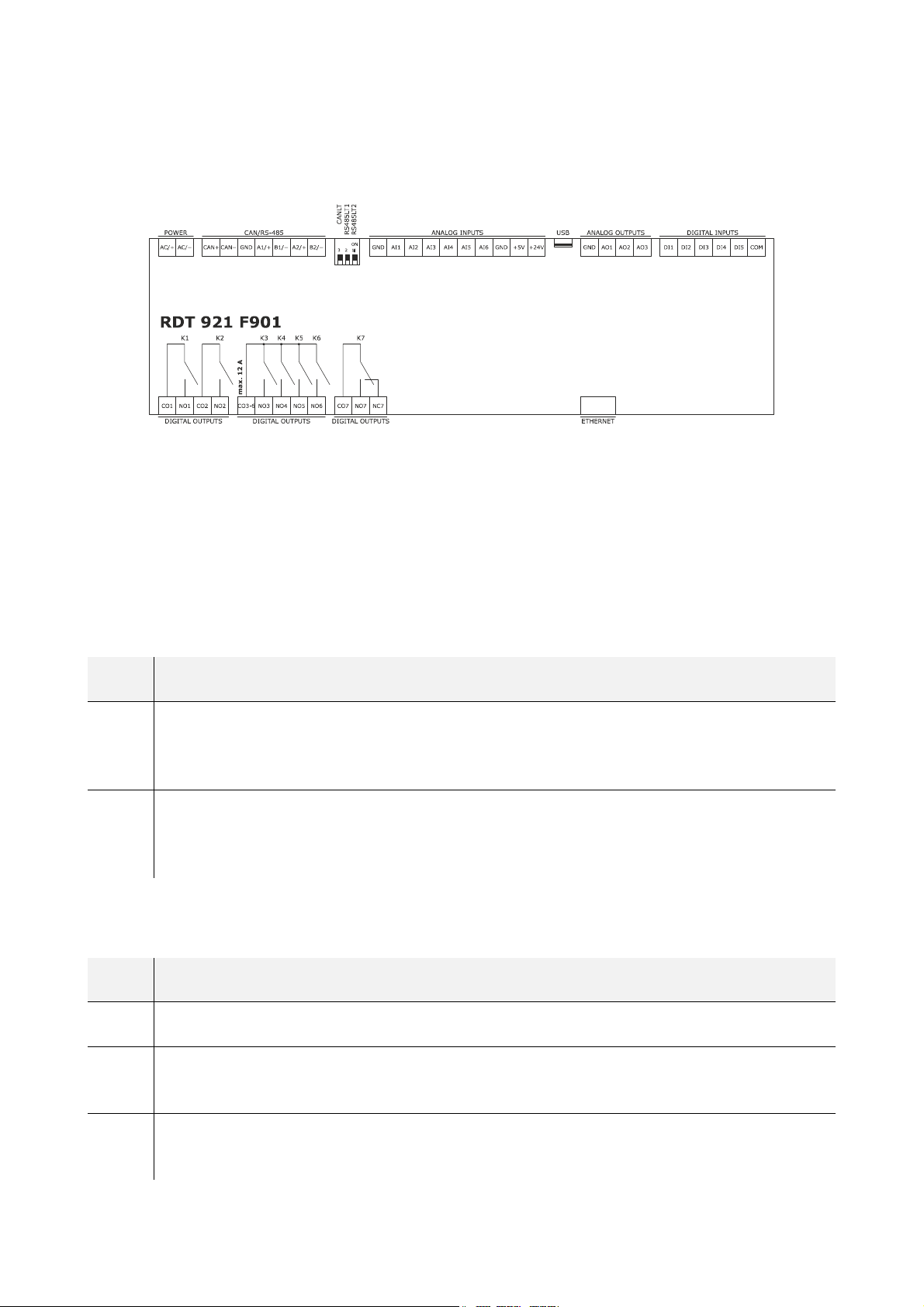
The following drawing shows the appearance of the devices.
The following table shows the meaning of the parts of the devices.
RDT921F901 | Hardware manual ver. 1.0 | Code 114RDT921E104SAU
PART MEANING
1 K1 and K2 digital outputs
2 K3, K4, K5 and K6 digital outputs
3 K7 digital outputs
4 Ethernet MODBUS TCP, Web Server, BACnet IP port
5 display and keypad (not available for the blind versions)
6 digital inputs
7 analog outputs
8 USB port
9 analog inputs
10
micro switch activating the Can Canbus terminal port, the RS-485 MODBUS master/slave port and the RS-485 MODBUS
slave port
11 RS-485 MODBUS slave, RS-485 MODBUS master/slave and CAN CANBUS ports
12 power supply
13 signalling LED
For additional information, please refer to the following chapters.
page 6 of 38
Sauter Italia S.p.A.
RDT921F901 | Hardware manual ver. 1.0 | Code 114RDT921E104SAU
3 DIMENSIONS AND INSTALLATION
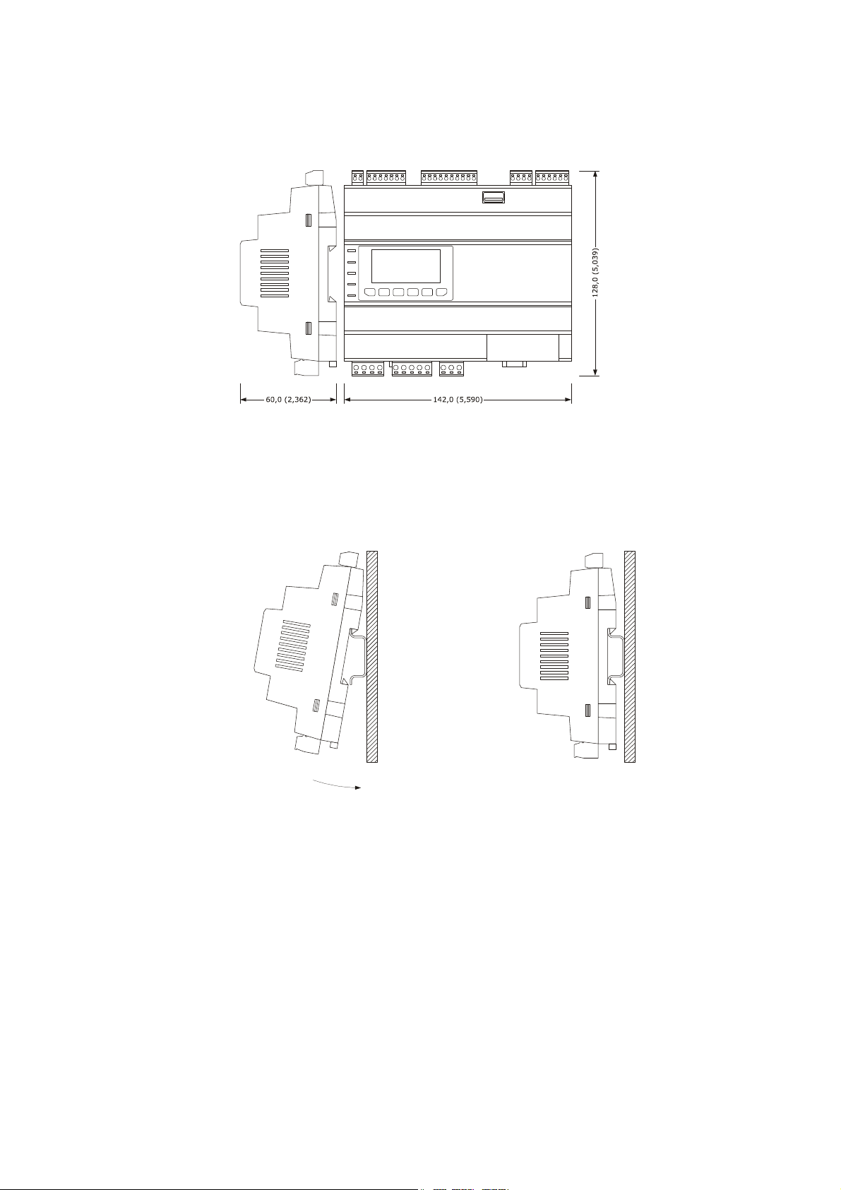
3.1 Dimensions:
The following drawing shows the measurements of the devices (8 DIN modules), in mm (in).
3.2 Installation
The device is installed on a DIN 35.0 x 7.5 mm (1.377 x 0.295 in) or 35.0 x 15.0 mm (1.377 x 0.590 in), track in a control panel.
To install the devices, please follow the instructions in the drawing below.
1
2
page 7 of 38
Sauter Italia S.p.A.
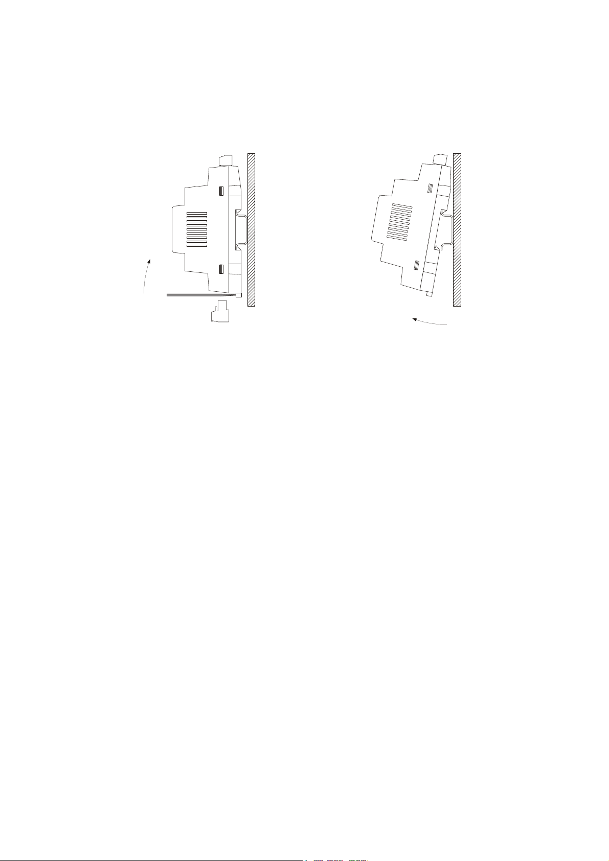
To remove the devices, first remove any screw-in removable terminal boards mounted in the lower part, then trigger the DIN track clip
with a screwdriver as show in the following picture:
3
RDT921F901 | Hardware manual ver. 1.0 | Code 114RDT921E104SAU
4
To install the devices again, first press the clip of the DIN track.
3.3 Installation warnings
-
-
-
make sure that the device work conditions (temperature of use, humidity, etc.) lie within the limits indicated; see chapter 7
“TECHNICAL DATA”
do not install the device near to any heat sources (heating elements, hot air ducts etc.), equipment containing powerful
magnets (large diffusers, etc.), areas affected by direct sunlight, rain, humidity, excessive dust, mechanical vibrations or
shocks
in compliance with Safety Standards, the device must be installed correctly and in a way to protect against any contact with
electric parts; all parts that ensure protection must be fixed in a way that they cannot be removed without the use of tools.
page 8 of 38
Sauter Italia S.p.A.
RDT921F901 | Hardware manual ver. 1.0 | Code 114RDT921E104SAU
4 ELECTRIC CONNECTION
4.1 Connectors
The following drawing shows the connectors of the devices.
4.2 Meaning of connectors
The following tables show the meaning of the various device connectors.
For additional information, please read chapter 7 "TECHNICAL DATA",
POWER
Device power supply (24 VAC/DC not insulated)
If the device runs on direct current, it shall be necessary to pay attention to the polarity of the supply voltage.
If the device is connected to a network of devices, it shall be necessary to:
-
-
check that the power supply of the devices included in the network are galvanically isolated.
the phase powering the device is the same as that of all the devices included in the network.
PART MEANING
device power supply:
AC/+
AC/-
ANALOG INPUTS
Analog inputs
Please see paragraph 6 "CONFIGURATION" for the settings of the analog inputs.
PART MEANING
GND analog inputs ground
AI1
-
-
device power supply:
-
-
analog input 1 settable by way of the PTC, NTC, Pt 1000, Ni 1000 probes configuration parameter, transducers 0-20 mA,
4-20 mA, 0-5 V ratiometric or 0-10 V
if the device is run by alternating current, connect the phase
if the device is run by direct current, connect the positive pole
if the device is run by alternating current, connect the neuter
if the device is run by direct current, connect the negative pole
AI2
analog input 2 settable by way of the PTC, NTC, Pt 1000, Ni 1000 probes configuration parameter, transducers 0-20 mA,
4-20 mA, 0-5 V ratiometric o 0-10 V
page 9 of 38
Sauter Italia S.p.A.
RDT921F901 | Hardware manual ver. 1.0 | Code 114RDT921E104SAU
AI3
AI4 analog input 4, settable by way of the PTC, NTC, Pt 1000, Ni 1000 probes configuration parameter
AI5 analog input 5, settable by way of the PTC, NTC, Pt 1000, Ni 1000 probes configuration parameter
AI6 analog input 6, settable by way of the PTC, NTC, Pt 1000, Ni 1000 probes configuration parameter
GND analog inputs ground
+5V 0-5 V (5VDC) ratiometric transducers power supply
+24V 0-20 mA, 4-20 mA and 0-10 V (24 VAC) transducers power supply
DIGITAL INPUTS
Digital inputs.
PART MEANING
DI1 digital input 1 (24 VAC/DC, 50/60 Hz or 2 KHz opto-isolated);
analog input 3 settable by way of the PTC, NTC, Pt 1000, Ni 1000 probes configuration parameter, transducers 0-20 mA,
4-20 mA, 0-5 V ratiometric o 0-10 V
DI2 digital input 2 (24 VAC/DC, 50/60 Hz o 2 KHz opto-isolated);
DI3 digital input 3 (24 VAC/DC, 50/60 Hz opto-isolated)
DI4 digital input 4 (24 VAC/DC, 50/60 Hz opto-isolated)
DI5 digital input 5 (24 VAC/DC, 50/60 Hz opto-isolated)
COM common digital inputs
ANALOG OUTPUTS
Analog outputs.
Please see paragraph 6 "CONFIGURATION" for the settings of the analog outputs.
PART MEANING
GND analog outputs ground
AO1 analog output 1, settable by way of the configuration parameter for PWM or 0-10V.
AO2 analog output 2, settable by way of the configuration parameter for PWM or 0-10 V
AO3 analog output 3, settable by way of the configuration parameter for 0-20 mA, 4-20 mA or 0-10 V
page 10 of 38

Sauter Italia S.p.A.
DIGITAL OUTPUTS
Digital outputs.
PART MEANING
CO1 common digital output 1
NO1
CO2 common digital output 1
NO2
usually open contact for digital output 1
according to model:
-
-
usually open contact for digital output 2
according to model:
-
-
electromechanical relay with 3 A res. @ 250 VAC
control for 24 VAC/DC, 600 mA max. solid state relays
electromechanical relay with 3 A res. @ 250 VAC
control for 24 VAC/DC, 600 mA max. solid state relays
RDT921F901 | Hardware manual ver. 1.0 | Code 114RDT921E104SAU
CO3-6 common digital output 3... 6
NO3 usually open contact for digital output 3 (electromechanical relay with 3 A res. @ 250 VAC)
NO4 usually open contact for digital output 4 (electromechanical relay with 3 A res. @ 250 VAC)
NO5 usually open contact for digital output 5 (electromechanical relay with 3 A res. @ 250 VAC)
NO6 usually open contact for digital output 6 (electromechanical relay with 3 A res. @ 250 VAC)
CO7 common digital output 7
NO7 usually open contact for digital output 7 (electromechanical relay with 3 A res. @ 250 VAC)
NC7 usually open contact for digital output 7
CAN/RS-485
RS-485 MODBUS slave, RS-485 MODBUS master/slave and CAN CANBUS ports
The communication protocol for the RS-485 MODBUS master/slave port can be set with the development environment.
For the settings for the RS-485 MODBUS slave, RS-485 MODBUS master/slave and CAN CANBUS ports, please refer to chapter 6
“CONFIGURATION”.
PART MEANING
CAN+ CAN CANBUS port positive pole
CAN- CAN CANBUS port negative pole
GND RS-485 MODBUS slave, RS-485 MODBUS master/slave and CAN CANBUS ports ground
A1/+ RS-485 MODBUS master/slave port positive pole
page 11 of 38

Sauter Italia S.p.A.
B1/- RS-485 MODBUS master/slave port negative pole
A2/+ RS-485 MODBUS slave port positive pole
B2/- RS-485 MODBUS slave port negative pole
The following table shows the Function codes supported by the device, provided that it works in commander mode with a MODBUS
communication protocol.
RDT921F901 | Hardware manual ver. 1.0 | Code 114RDT921E104SAU
FUNCT.
CODE
FC 01 read coils
FC 02 read discrete inputs
FC 03 read multiple registers
FC 04 read input registers
FC 05 write single coil
FC 06 write single register
FC 08 diagnostic
FC 15 write multiple coils
FC 16 write multiple registers
MEANING
FC 23 read write multiple registers (maximum 10 registers)
The RS-485 MODBUS slave and RS-485 MODBUS master/slave ports can be used for one of the following operations:
-
-
-
The CAN CANBUS port can be used to connect the device to the remote user interfaces of the RDB900 range
The maximum number of devices that can be comprised in the CAN network (32) depends on the BUS load; the BUS load, in turn,
depends on the baud rate of the CANBUS communication and on the type of device (for instance, a CAN network can comprise 1
controller and 4 remote user interfaces with a baud rate of 500,000 baud).
USB
USB port
Through the USB port it is possible to carry out one of the following actions:
-
-
-
-
-
Please see paragraph 6 "CONFIGURATION" for the settings of the USB port.
device configuration (through the Parameters Manager set-up software system)
device supervision (through the Sauter Vision Center system monitoring and supervision (via Web) system)
MODBUS master function use with regard to other slave devices.
upload and download of application software (through the development environment or USB flash drive)
application software debug (through development environment)
device configuration (through the Parameters Manager set-up software system or a USB flash drive)
file transfer (through the development environment)
data logging (through a USB flash drive).
page 12 of 38

Sauter Italia S.p.A.
ETHERNET
Ethernet MODBUS TCP, Web Server, BACnet IP port
Please see paragraph 6 "CONFIGURATION" for the settings of the Ethernet MODBUS TCP, Web Server, BACnet IP port.
RDT921F901 | Hardware manual ver. 1.0 | Code 114RDT921E104SAU
4.3 Insertion of the termination resistor of the CAN CANBUS port
To reduce reflections on the signal transmitted through the cables connecting the devices to a CAN network it is necessary to insert the
termination resistor of the first and last elements of the network.
To insert the termination resistor, place the micro-switch 3 in the ON position.
4.4 Insertion of the RS-485 MODBUS master/slave port termination resistor
To reduce reflections on the signal transmitted through the cables connecting the devices to a RS-485 network it is necessary to insert
the termination resistor of the first and last elements of the network.
To insert the termination resistor, place the micro-switch 2 in the ON position.
4.5 Insertion of the RS-485 MODBUS slave port termination resistor
To reduce reflections on the signal transmitted through the cables connecting the devices to a RS-485 network it is necessary to insert
the termination resistor of the first and last elements of the network.
To insert the termination resistor, place the micro-switch 1 in the ON position.
4.6 RS-485 MODBUS master/slave port polarisation
The devices can polarise the RS-485 MODBUS master/slave port; the polarisation can be set through the configuration parameter.
4.7 RS-485 MODBUS slave port polarisation
The devices cannot polarise the RS-485 MODBUS slave port; the polarisation must be carried out by another device.
page 13 of 38

Sauter Italia S.p.A.
RDT921F901 | Hardware manual ver. 1.0 | Code 114RDT921E104SAU
4.8 Example of electric connection
The following drawing shows and example of the electric connection of the devices.
4.9 Warnings for the electric connection
-
-
-
-
-
-
-
-
-
do not use electric or pneumatic screwdrivers on the device terminal board
if the device has been taken from a cold to hot place, humidity could condense inside; wait about 1 hour before powering it
make sure that the power supply voltage, the frequency and the operational electric power of the device, correspond with
those of the local power supply; see chapter 8 “TECHNICAL DATA”
disconnect the device power supply before proceeding with any type of maintenance
connect the device to a RS-485 network using a twisted pair
connect the device to a CAN network using a twisted pair
position the power cables as far away as possible from the signal cables
do not use the device as a safety device
for repairs and information regarding the device, contact the SAUTER ITALIA sales network.
page 14 of 38

Sauter Italia S.p.A.
RDT921F901 | Hardware manual ver. 1.0 | Code 114RDT921E104SAU
5 USER INTERFACE
5.1 Keypad
The following table shows the meaning of the keypad of the devices.
KEY PRESET FUNCTION
cancel, hereinafter also "ESC key"
left shift, hereinafter also "LEFT key"
increase, hereinafter also "UP key"
decrease, hereinafter also "DOWN key"
right shift, hereinafter also "RIGHT key"
confirm, hereinafter also "ENTER key"
The keypad is not available in the blind versions.
5.2 LED warning lights
The following table shows the meaning of the LED warning lights of the devices.
LED MEANING
power supply LED
ON
RUN
if it is on, the device is powered
if it is off, the device is not powered
run LED
if it is on, the application software shall be compiled and executed in release mode
if it is flashing very slowly, the application software shall be compiled in debug mode
if it is flashing slowly, the application software shall be executed in debug mode
if it is flashing quickly, the application software shall be compiled, executed in debug mode and stopped at a breakpoint
if it is off:
-
-
system alarm LED
if it is on, a system alarm has been triggered that cannot be reset through the application software
if it is flashing very slowly, the external FLASH memory is being accessed
if it is flashing slowly, a system alarm had been triggered with automatic reset
if it is flashing quickly, a system alarm had been triggered with manual reset
if it is off, no system alarm has been triggered
the device is not compatible with the application software
the device is not authorised to operate with the Special ABL (Application Block Libraries)
page 15 of 38

Sauter Italia S.p.A.
CAN CANBUS communication LED
if it is on, the device is configured to communicate via CAN CANBUS with another device, but the communication has not
CAN
been established
if it is flashing slowly, the CAN CANBUS communication has been established, but is not entirely correct
if it is flashing quickly, the CAN CANBUS communication shall established and be entirely correct
if it is off, no CAN CANBUS communication is in progress
RDT921F901 | Hardware manual ver. 1.0 | Code 114RDT921E104SAU
L1
For additional information, please refer to the following chapters.
Auxiliary LED
The operation of this LED can be set via development environment
page 16 of 38

Sauter Italia S.p.A.
RDT921F901 | Hardware manual ver. 1.0 | Code 114RDT921E104SAU
6 CONFIGURATION
6.1 Configuration of a built-in LCD controller
To access the procedure, proceed as follows:
1.
2.
To access the sub-menus, proceed as follows:
3.
4.
To access the "Parameters", "Networks", "Password" and "Backup/Restore" sub-menus, proceed as follows:
5.
6.
7.
8.
9.
To adjust a parameter, proceed as follows:
10.
11.
12.
13.
14.
To change the language of the application software, proceed as follows:
15.
16.
17.
18.
To change the current date and time, proceed as follows:
19.
20.
21.
22.
23.
To copy the controller parameters to a USB peripheral device, proceed as follows:
24.
25.
26.
27.
28.
Check that the power is on.
Keep the UP and DOWN keys pressed for 2 s: the following menu (hereinafter, the "Main menu") shall appear on the
display,
<RDT 921 F901>
Info
English
Parameters
Networks
Backup/Restore
Diagnostic
Debug
Press and release the UP or DOWN key to select the relevant sub-menu.
Press and release the ENTER key.
Starting from point 2, press and release the UP or DOWN key to select the relevant sub-menu.
Press and release the ENTER key.
Press and release the ENTER key again to set the password
Press and release the DOWN key repeatedly to set "-19".
Press and release the ENTER key again.
From point 9, press and release the UP or DOWN key to select the parameter (some parameters are included in sub-
menus; press and release the ENTER key to access them).
Press and release the ENTER key.
Press and release the UP or DOWN key to change the value.
Press and release the ENTER key to confirm the set value
Press and release the ESC key repeatedly to go back to the "Main menu".
From point 2, press and release the UP or DOWN key to select the "Language" item (the default setting is "English").
Press and release the ENTER key.
Press and release the UP or DOWN key to change the language.
Press and release the ENTER key to confirm the set value
Starting from point 2, press and release the UP or DOWN key to select the "Current date and time" item.
Press and release the ENTER key.
Press and release the UP or DOWN key to change the value.
Press and release the ENTER or RIGHT keys to confirm the value and change the following field (press and release the LEFT
or RIGHT keys to move between fields)
Repeat points 21 and 22.
Check that the power is on.
Connect the peripheral device to the controller.
Access the "Backup/Restore" sub-menu, then choose "Parameters key" (Choose "Backup Memory" for the backup memory)
Press and release the UP or DOWN key to select "Application par" to copy the parameters of the application software, or
"Hardware config" to copy the configuration parameters.
Press and release the UP or DOWN key to select "Save on the key"
page 17 of 38

Sauter Italia S.p.A.
29.
30.
To copy the USB peripheral device parameters to the controller, proceed as follows:
31.
32.
33.
34.
35.
36.
Copying the peripheral device parameters tp the controller is allowed provided that the controllers firmware coincides.
To exit the procedure, proceed as follows:
37.
Disconnect the power supply after changing the configuration.
Press and release the ENTER key: the parameters shall be copied from the controller into the peripheral device (the process
usually requires a few seconds; if an error should be present, the System alarm LED (see paragraph 5.2 LED warning
lights) shall light up and an Err. value shall be input in the Key Par (in the "Diagnostic" sub-menu) parameter.
Disconnect the peripheral device
Check that the power is on.
Connect the peripheral device to the controller.
Access the "Backup/Restore" sub-menu, then choose "Parameters key" (Choose "Backup Memory" for the backup memory)
Press and release the UP or DOWN key to select "Restore from the key".
Press and release the ENTER key: the parameters shall be copied from the peripheral device into the controller (the process
usually requires a few seconds; if an error should be present, the System alarm LED (see paragraph 5.2 LED warning
lights) shall light up and an Err. value shall be input in the Key Par (in the "Diagnostic" sub-menu) parameter.
Disconnect the peripheral device
Press and release the ESC key repeatedly; any changes shall not be saved.
RDT921F901 | Hardware manual ver. 1.0 | Code 114RDT921E104SAU
6.2 Configuration of a controller through a remote user interface
The following procedures show an example of how to configure a controller through a remote user interface (in the example, RDB 900
F901) and its user interface.
Proceed as follows:
1.
2.
3.
4.
5.
6.
7.
8.
9.
10.
11.
The default address of the CAN node of a controller is 1 (operate on the remote user interface to set the "NW Node" parameter to [ 1 ]
1).
Disconnect the power supply of the controller and the interface.
Connect the controller to the interface through the CAN CANBUS port; see chapter 4 “ELECTRIC CONNECTION”.
Keep the ESC and RIGHT keys pressed for 2 sec.
Connect the power supply of the controller and the interface.
When the interface display shows the following menu, release the ESC and RIGHT keys.
RDT 900 F901
Parameters
Contrast
CAN Network
Modbus
Info
Debug
Press and release the UP or DOWN key to select "CAN Network".
Press and release the ENTER key.
Press and release the ENTER key again to set the password
Press and release the DOWN key repeatedly to set "-19".
Press and release the ENTER key again.
Set the "NW Node" parameter using the UP or DOWN keys to select the parameter and the ENTER key to change and
confirm the relevant value.
page 18 of 38

Sauter Italia S.p.A.
12.
13.
14.
15.
16.
17.
Disconnect the user interface power supply
Connect the user interface power supply
Keep the LEFT and ENTER keys pressed for 2 s: the following menu shall appear on the display,
Press and release the UP or DOWN key to select the device
Press and release the ENTER key: the "Main menu" of the device shall be shown on the display.
Proceed as shown in paragraph 6.1 “Configuration of a built-in LCD controller”.
Network Status
Loc 99 OK > >
1 1 OK > >
2 2 OK > >
3 0 - > >
4 0 - > >
5 0 - > >
RDT921F901 | Hardware manual ver. 1.0 | Code 114RDT921E104SAU
page 19 of 38

Sauter Italia S.p.A.
6.3 List of configuration parameters
RDT921F901 | Hardware manual ver. 1.0 | Code 114RDT921E104SAU
6.3.1
The following table shows the meaning of the configuration parameters of the "Info" menu.
Configuration parameters of the "Info" menu
PARAM. MIN. MAX. M. U. DEF. DESCRIPTION
PROJ parameter available in read only mode
FW parameter available in read only mode
HW parameter available in read only mode
SW parameter available in read only mode
SN parameter available in read only mode
MASK parameter available in read only mode
Information on the application project (project, version and
revision)
Information on the firmware (code, version, revision and sub-
revision)
Information on the hardware (version, revision, generic (G) or
special (S))
Information on the development environment (version and
revision).
Information on the serial number and the results of the
production tests
Information on the mask (depends on the manufacturer's coding
system)
DATE parameter available in read only mode date and time of the latest compilation of the application project.
6.3.2
The following table shows the meaning of the configuration parameters of the "Parameters" menu.
Configuration parameters of the "Parameters" menu
PARAM. MIN. MAX. M. U. DEF. DESCRIPTION
type of probe analog port 1
NI1000 = probe Ni 1000
PTC
= PTC probe
NTC
= NTC probe
0-20mA = Transducer 0-20 mA
AI1 - - - - - - - - - NTC
4-20mA = Transducer 4-20 mA
0-5V
= Transducer 0-5 V ratiometric
0-10V
= Transducer 0-10 V
PT1000 = Pt 1000 probe
NTCK2 = Type 2 NTC probe
NTCK3 = Type 3 NTC probe
RESIST = electric resistance reading
page 20 of 38

Sauter Italia S.p.A.
AI2 - - - - - - - - - NTC
AI3 - - - - - - - - - NTC
RDT921F901 | Hardware manual ver. 1.0 | Code 114RDT921E104SAU
type of probe analog port 2
NI1000 = probe Ni 1000
PTC
= PTC probe
NTC
= NTC probe
0-20mA = Transducer 0-20 mA
4-20mA = Transducer 4-20 mA
0-5V
= Transducer 0-5 V ratiometric
0-10V
= Transducer 0-10 V
PT1000 = Pt 1000 probe
NTCK2 = Type 2 NTC probe
NTCK3 = Type 3 NTC probe
RESIST = electric resistance reading
type of probe analog port 3
NI1000 = probe Ni 1000
PTC
= PTC probe
NTC
= NTC probe
0-20mA = Transducer 0-20 mA
4-20mA = Transducer 4-20 mA
0-5V
= Transducer 0-5 V ratiometric
0-10V
= Transducer 0-10 V
PT1000 = Pt 1000 probe
NTCK2 = Type 2 NTC probe
NTCK3 = Type 3 NTC probe
RESIST = electric resistance reading
AI4 - - - - - - - - - NTC
AI5 - - - - - - - - - NTC
AI6 - - - - - - - - - NTC
type of probe analog port 4
NI1000 = probe Ni 1000
PTC
= PTC probe
NTC
= NTC probe
PT1000 = Pt 1000 probe
NTCK2 = Type 2 NTC probe
NTCK3 = Type 3 NTC probe
RESIST = electric resistance reading
type of probe analog port 5
NI1000 = probe Ni 1000
PTC
= PTC probe
NTC
= NTC probe
PT1000 = Pt 1000 probe
NTCK2 = Type 2 NTC probe
NTCK3 = Type 3 NTC probe
RESIST = electric resistance reading
type of probe analog port 6
NI1000 = probe Ni 1000
PTC
= PTC probe
NTC
= NTC probe
PT1000 = Pt 1000 probe
NTCK2 = Type 2 NTC probe
NTCK3 = Type 3 NTC probe
RESIST = electric resistance reading
page 21 of 38

Sauter Italia S.p.A.
Al Err Time 0 240 s 2
AO impulse 1 50 ms/10 20 duration of the cut phase impulse
AO1 - - - - - - - - - 0-10V
freq 10 2000 Hz 1000 frequency of the analog port 1 PWM-type signal
delay ph. 0 50 ms/10 0 displacement of the phase-cutting impulse from analog port 1
AO2 - - - - - - - - - 0-10V
RDT921F901 | Hardware manual ver. 1.0 | Code 114RDT921E104SAU
analog ports time-out (if no communication with an analog port
is detected after this span of time, the controller notifies an
analog input error)
type of signal analog port 1
FAN
= FAN (for cut phase module)
0-10V
= 0-10 V
PWM
= PWM (Pulse With Modulation)
type of signal analog port 2
FAN
= FAN (for phase-cutting module)
0-10V
= 0-10 V
PWM
= PWM (Pulse With Modulation)
freq 10 2000 Hz 1000 frequency of the analog port 2 PWM-type signal
delay ph. 0 50 ms/10 0 displacement of the phase-cutting impulse from analog port 2
type of signal analog port 3
AO3 - - - - - - - - - 0-10V
I/O Timeout
(1)
AI1 filter OFF ON - - - ON analog input 1 filter coefficient
AI2 filter OFF ON - - - ON analog input 2 filter coefficient
AI3 filter OFF ON - - - ON analog input 3 filter coefficient
AI4 filter OFF ON - - - ON analog input 4 filter coefficient
1 240 s 60
0-20mA = 0-20 mA
4-20mA = 4-20 mA
0-10V
= 0-10 V
CANBUS communication time-out to check the remote I/O values
(after this span of time has elapsed with no CANBUS
communication, the controller I/O is disabled)
AI5 filter OFF ON - - - ON analog input 5 filter coefficient
AI6 filter OFF ON - - - ON analog input 6 filter coefficient
DI1 filter OFF ON - - - ON digital input 1 filter coefficient
DI2 filter OFF ON - - - ON digital input 2 filter coefficient
page 22 of 38

Sauter Italia S.p.A.
DI3 filter OFF ON - - - ON digital input 3 filter coefficient
DI4 filter OFF ON - - - ON digital input 4 filter coefficient
DI5 filter OFF ON - - - ON digital input 5 filter coefficient
RDT921F901 | Hardware manual ver. 1.0 | Code 114RDT921E104SAU
access to the level first page enabled by pressing a combination
of keys
YES
= yes, proceeding as follows:
-
En. Prg
Level (1)
- - - - - - - - - NO
-
-
keep the ENTER key pressed for 3 sec. to
access the first page of level 1
keep the ENTER and ESC keys pressed
for 3 sec. to access the first page of level
2
keep the LEFT and RIGHT keys pressed
for 3 sec. to access the first page of level
3
restriction between the access passwords of the various levels
NO
Password
indi (1)
Ena BkMem
RTC (1)
Backlight (2) - - - - - - - - - TIME
B. Time (2) 0 60 s 240
Contrast (2) 0 100 - - - 50 display contrast
- - - - - - - - - NO
- - - - - - - - - YES clock and backup storage functions enabled
YES
type of backlight
OFF
ON
TIME
backlight duration (only if the Backlight parameter is set in TIME
mode)
= It is not necessary to set a password to access
= it is necessary to set a password to access each
= the backlight is never on
= the backlight is always on
= the backlight stays on for the period of time after
the levels below the one already accessed
level
the latest key operation set with the B. Time
parameter
Date Char
Sep (2)
Year format
(2)
- - - - - - - - - / date separator ASCII character
year format
- - - - - - - - - YY
YY
YYYY
page 23 of 38
= two digits (e.g. 13)
= four digits (e.g. 2013)

Sauter Italia S.p.A.
Date format
(2)
Time Char
Separator
(2)
- - - - - - - - - D-M-Y
- - - - - - - - - : time separator ASCII character
RDT921F901 | Hardware manual ver. 1.0 | Code 114RDT921E104SAU
date format
D-M-Y
= day, month and year
M-D-Y
= month, day and year
Y-M-D
= year, month and day
Time With
Sec (2)
Time AM/PM
(2)
- - - - - - - - - YES
- - - - - - - - - NO
time displayed with seconds
YES
= yes
time format
NO
YES
= 24 h (e.g. 15:20)
= 12 h (e.g. 3:20 PM)
page 24 of 38

Sauter Italia S.p.A.
6.3.3
The following table shows the meaning of the configuration parameters of the "CAN Network" section of the "CAN Bus" sub-menu or the
"Networks" menu.
PARAM. MIN. MAX. M. U. DEF. DESCRIPTION
MyNode 1 127 - - - 1 local CAN node or device address
Configuration parameters of the "CAN Bus" sub-menu of the "Networks" menu
RDT921F901 | Hardware manual ver. 1.0 | Code 114RDT921E104SAU
Master - - - - - - - - - YES
Baud - - - - - - - - - 20K
Timeout 1 60 s 5
Network
Node
TSEG1 - - - - - - - - - - - - reserved
[1] 0 [32] 127 - - - [1] 99
enabled to function as master in a CAN network
YES
baud rate of the CAN-type communication
20K
50K
125K
500K
remote CAN-type communication timeout, i.e., communication
with the other network elements (after the time set with this
parameter has elapsed with no CAN-type communication with an
element, the element is disabled).
address of the CAN nodes or of the other network elements (e.g.
for [1] 2)
[1]
2
= yes
= 20.000 baud
= 50.000 baud
= 125.000 baud
= 500.000 baud
= node
= node address
TSEG2 - - - - - - - - - - - - reserved
SJW - - - - - - - - - - - - reserved
BTR - - - - - - - - - - - - reserved
CAN machine status
INIT
= initialisation
Status parameter available in read-only mode
Bus Status parameter available in read-only mode
Cnt Rx parameter available in read-only mode number of packets received
STOPPED = stop CAN
OPERAT = operating
PRE-OP = in pre-operating mode
CAN bus status
OK
WARNING = attention
PASSIVE = bus in receiving mode only
BUS OFF = bus stopped
= status OK
page 25 of 38

Sauter Italia S.p.A.
Cnt Tx parameter available in read-only mode number of packets sent
Cnt Ovf parameter available in read-only mode number of overflow packets
Cnt Passive parameter available in read-only mode number of passages to the passive state
Cnt Bus Off parameter available in read-only mode number of passages to the passive state
6.3.4
The following table shows the meaning of the configuration parameters of the "UART1" sub-menu or the "Networks" menu concerning
the RS-485 MODBUS master/slave port.
The parameters are visible if the application software allows the port to be configured to support the MODBUS communication protocol.
PARAM. MIN. MAX. M. U. DEF. DESCRIPTION
Configuration parameters of the "UART1" sub-menu of the "Networks" menu
RDT921F901 | Hardware manual ver. 1.0 | Code 114RDT921E104SAU
Address 1 247 - - - 1
Baudrate - - - - - - - - - 9600
Parity - - - - - - - - - EVEN
Stop - - - - - - - - - 1 BIT
MODBUS address of the device (significant only if the
communication protocol is of the MODBUS slave type)
baud rate of the MODBUS-type communication
1200
= 1.200 baud
2400
= 2.400 baud
4800
= 4.800 baud
9600
= 9.600 baud
19200
= 19.200 baud
28800
= 28.800 baud
38400
= 38.400 baud
57600
= 57.600 baud
MODBUS-type communication parity
NONE
= none
ODD
= odd
EVEN
= even
number of stop bits of the MODBUS-type communication
1 BIT
= 1 bit
2 BIT
= 2 bit
Timeout 2 240 s 10
Polarization - - - - - - - - - NO
local MODBUS-type communication timeout, i.e., device timeout
(this parameter sets a delay from the sending of a request after
which, if no answer is received, the request sending is considered
failed and the next request is sent; it is significant only if the
communication protocol is of the MODBUS master type).
RS-485 MODBUS slave port polarisation
NO
YES
page 26 of 38
= the device does not polarise the RS-485 slave
port
= the device polarises the RS-485 slave port

Sauter Italia S.p.A.
6.3.5
The following table shows the meaning of the configuration parameters of the "UART2" sub-menu or the "Networks" menu concerning
the RS-485 MODBUS slave port.
The parameters are visible if the application software allows the port to be configured to support the MODBUS communication protocol.
PARAM. MIN. MAX. M. U. DEF. DESCRIPTION
Configuration parameters of the "UART2" sub-menu of the "Networks" menu
RDT921F901 | Hardware manual ver. 1.0 | Code 114RDT921E104SAU
Address 1 247 - - - 1
Baudrate - - - - - - - - - 9600
Parity - - - - - - - - - EVEN
Stop - - - - - - - - - 1 BIT
MODBUS address of the device (significant only if the
communication protocol is of the MODBUS slave type)
baud rate of the MODBUS-type communication
1200
= 1.200 baud
2400
= 2.400 baud
4800
= 4.800 baud
9600
= 9.600 baud
19200
= 19.200 baud
28800
= 28.800 baud
38400
= 38.400 baud
57600
= 57.600 baud
MODBUS-type communication parity
NONE
= none
ODD
= odd
EVEN
= even
number of stop bits of the MODBUS-type communication
1 BIT
= 1 bit
2 BIT
= 2 bit
local MODBUS-type communication timeout, i.e., device timeout
(this parameter sets a delay from the sending of a request after
Timeout 0 9999 ms 1000
6.3.6
The following table shows the meaning of the configuration parameters of the "Ethernet" sub.menu of the "Networks" menu.
Adr Gateway - - - - - - - - - - - - 192.168.0.1 gateway address
Configuration parameters of the "Ethernet" sub-menu of the "Networks" menu
PARAM. MIN. MAX. M. U. DEF. DESCRIPTION
MAC parameter available in read-only mode reserved
Eth IP - - - - - - - - - 192.168.0.2 IP address
Subnet
Mask
- - - - - - - - - - - -
255.255.255.0
which, if no answer is received, the request sending is considered
failed and the next request is sent; it is significant only if the
communication protocol is of the MODBUS master type).
subnet Mask
page 27 of 38

Sauter Italia S.p.A.
RDT921F901 | Hardware manual ver. 1.0 | Code 114RDT921E104SAU
Port MB
Slave
Port MB
Master
Web Server
Port
6.3.7
The following table shows the meaning of the configuration parameters of the "USB" sub-menu of the "Networks" menu.
PARAM. MIN. MAX. M. U. DEF. DESCRIPTION
USB Status
Device
Device
Status Idle
Speed
- - - - - - - - - - - - MODBUS slave port
- - - - - - - - - - - - MODBUS master port
- - - - - - - - - - - - Web Server port
Configuration parameters of the "USB" sub-menu of the "Networks" menu
parameter available in read-only mode reserved
parameter available in read-only mode reserved
6.3.8
The following table shows the meaning of the configuration parameters of the "Password" menu.
Configuration parameters of the "Password" menu
PARAM. MIN. MAX. M. U. DEF. DESCRIPTION
-32768 32768 - - - 0 value of the level 1 access password
Level 1:
- - - - - - - - - ON
-32768 32768 - - - 0 value of the level 2 access password
Level 2:
- - - - - - - - - ON
enabling of the level 1 access password
OFF
ON
enabling of the level 2 access password
OFF
ON
= no password needs to be set to access level 1
= it is necessary to set a password to access level 1
= no password needs to be set to access level 2
= it is necessary to set a password to access level 2
Level 3:
-32768 32768 - - - 0 value of the level 3 access password
enabling of the level 3 access password
- - - - - - - - - ON
OFF
ON
page 28 of 38
= no password needs to be set to access level 3
= it is necessary to set a password to access level 3

Sauter Italia S.p.A.
-32768 32768 - - - 0 value of the level 4 access password
RDT921F901 | Hardware manual ver. 1.0 | Code 114RDT921E104SAU
Level 4:
- - - - - - - - - ON
-32768 32768 - - - 0 value of the level 5 access password
Level 5:
- - - - - - - - - ON
Timeout 0 240 s 240
6.3.9
The following table shows the meaning of the configuration parameters of the "Diagnostics" menu.
Configuration parameters of the "Diagnostics" menu
PARAM. MIN. MAX. M. U. DEF. DESCRIPTION
enabling of the level 4 access password
OFF
= no password needs to be set to access level 4
ON
enabling of the level 5 access password
OFF
ON
timeout of access passwords (after this time has elapsed from the
latest keypad operation, it is necessary to set a new password to
access the relevant level, if so required).
= it is necessary to set a password to access level 4
= no password needs to be set to access level 5
= it is necessary to set a password to access level 5
Memory parameter available in read-only mode
RTC parameter available in read-only mode
STACK parameter available in read-only mode
5V RATIO parameter available in read-only mode
24V
SENSOR
parameter available in read-only mode
status of non-volatile memory
OK
ERR
clock status
OK
ERR
LOW
DISAB = disabled
stack status
OK
ERR
status of the voltage supply of the ratiometric transducers
OK
ERR
status of the supply voltage of 0-20 mA, 4-20 mA and 0-10 V
transducers
OK
ERR
= no error
= error
= no error
= error
= data loss
= no error
= error (overflow)
= no error
= error (voltage out of range)
= no error
= error (voltage out of range)
page 29 of 38

Sauter Italia S.p.A.
MATH parameter available in read-only mode
KEY PAR parameter available in read-only mode
6.3.10
The following table shows the meaning of the configuration parameters of the "Debug" menu.
PARAM. MIN. MAX. M. U. DEF. DESCRIPTION
Configuration parameters of the "Debug" menu
RDT921F901 | Hardware manual ver. 1.0 | Code 114RDT921E104SAU
math status
OK
ERR
result of the upload or download of the application software
parameters or of a configuration through USB drive.
OK
ERR
= no error
= error (overflow, under flow, division by zero or
NaN)
= procedure completed successfully
= procedure not completed successfully
Main run
time
max main
time
free stack
main
100ms run
time
100 ms max
time
free stack
100 ms
5V PROBE parameter available in read-only mode measurement of voltage supply of the ratiometric transducers
24V PROBE parameter available in read-only mode
parameter available in read-only mode application software main cycle time (in ms)
parameter available in read-only mode application software maximum main cycle time (in ms)
parameter available in read-only mode minimum free stack main (in byte)
parameter available in read-only mode application software run time timed at 100 ms
parameter available in read-only mode application software maximum run time timed at 100 ms
parameter available in read-only mode
application software free stack of the interrupt cycle at 100 ms (in
byte)
measurement of the supply voltage of 0-20 mA, 4-20 mA and 0-
10 V transducers
24V parameter available in read-only mode measurement of the supply voltage coming from the upper board
Notes:
(1)
(2)
to display the parameter, press the RIGHT key
to display the parameter, press the RIGHT key; this parameter is not available in the built-in LED and blind versions.
page 30 of 38

Sauter Italia S.p.A.
7 TECHNICAL DATA
7.1 Technical data
Purpose of the command device: operating command device.
RDT921F901 | Hardware manual ver. 1.0 | Code 114RDT921E104SAU
Construction of the command
device:
Container: grey self-extinguishing.
Heat and fire protection class: D.
Dimensions:
Method of mounting the
command device:
Protection grade:
Connections
built-in electronic device.
142.0 x 128.0 x 60.0 mm (5.590 x 5.039 x 2.362 in; L x H x D); 8 DIN modules
The dimensions refer to the device with all the screw-in removable terminal boards in place.
on a DIN 35.0 x 7.5 mm (1.377 x 0.295 in) or 35.0 x 15.0 mm (1.377 x 0.590 in), track in
a control panel.
-
-
-
-
-
-
IP20 overall
IP40 for the front.
screw in removable terminal board, male only 3,5 mm pitch (0,137 in) for wires
up to 1,5 mm² (0,0028 in²): power supply, analog inputs, digital inputs, analog
outputs and ports RS-485 MODBUS slave, RS-485 MODBUS master/slave and
CAN CANBUS
screw in removable terminal board, male only 5 mm pitch (0,196 in) for wires
up to 2,5 mm² (0,0038 in²): digital outputs
type A USB connector: USB port
RJ45 F phone connector: MODBUS TCP, Web Server, BACnet IP Ethernet port.
page 31 of 38

Sauter Italia S.p.A.
The maximum lengths of the connection cables are:
-
-
-
-
-
-
-
-
-
-
-
To wire the device, the use of the CJAV31 kit (to be ordered separately) is recommended:
screw-in removable terminal boards, female only, 3.5 mm pitch (0.137 in) for wires up to
1.5 mm² (0,0028 in²) and screw-in removable terminal boards, female only, 5 mm pitch
(0.196 in) for wires up to 2.5 mm² (0,0038 in²) .
To program the device, the use of the 0810500018 or 0810500020 connection cables (to be
ordered separately) s recommended: the 0810500018 cable is 2.0 m (6.56 ft) long , the
0810500020 cable is 0.5 m (1.640 ft) long.)
power supply: 100 m (328 ft)
analog inputs: 100 m (328 ft)
transducers power supply: 100 m (328 ft)
digital inputs: 100 m (328 ft)
analog outputs PWM: 1 m (3.280 ft)
analog outputs 0-20 mA, 4-20 mA and 0-10 V: 100 m (328 ft)
digital outputs (electromechanical relay): 100 m (328 ft)
digital outputs (controls for solid state relays) 100 m (328 ft)
RS-485 MODBUS slave and RS-485 MODBUS master/slave ports: 1,000 m
(3,280 ft); please refer also to the MODBUS specifications and implementation
guides available at http://www.modbus.org/specs.php
CAN CANBUS port:
-
-
-
-
USB port: 1 m (3.280 ft)
1.000 m (3.280 ft) with baud rate 20.000 baud
500 m (1.640 ft) with baud rate 50.000 baud
250 m (820 ft) with baud rate 125.000 baud
50 m (164 ft) with baud rate 500.000 baud
RDT921F901 | Hardware manual ver. 1.0 | Code 114RDT921E104SAU
-
Operating temperature:
Storage temperature: from -25 to 70 °C (from -13 to 158 °F).
Humidity for use: from 10 to 90 % relative humidity without condensate.
Command device pollution
situation:
Height at which it is used: from 0 to 2,000 m (from 0 to 6,591 ft).
Height at which it can be
transported:
Environmental standards:
EMC standards:
-
2.
from 0 to 3,048 m (from 0 to 10,000 ft).
-
-
-
-
-
from -10 to 55 °C (from 14 to 131 °F) for the built-in models
from -20 to 55 °C (from -4 to 131 °F) for the blind models
RoHS 2011/65/CE
WEEE 2012/19/EU
REACH (CE) regulation n. 1907/2006.
EN 60730-1
IEC 60730-1.
page 32 of 38

Sauter Italia S.p.A.
Power supply:
Rated impulse voltage: 4 KV.
Overvoltage category: III.
Class and structure of software: A.
-
-
supplied by a class 2 circuit.
Protect the power supply with a 2A-T 250 V fuse
If the device runs on direct current, it shall be necessary to pay attention to the polarity of
the supply voltage.
integrated (with primary lithium battery)
RDT921F901 | Hardware manual ver. 1.0 | Code 114RDT921E104SAU
24 VAC, 50/60 Hz (±3 Hz), 20 VA max. not insulated
20... 40 VDC, 12 W max. not insulated
Clock:
Digital inputs:
Battery autonomy without power supply: 5 years at 25 °C (77 °F).
Drift: ≤ 30 s/ month at 25 °C (77 °F).
5 inputs:
-
-
Ratiometric transducers 0-5 V power supply: 5 VDC (+0 %, -12 %), 60 mA max.
Transducers power supply 0-20 mA, 4-20 mA e 0-10 V: 12 DC (+50 %, -25 %),
120 mA max.
The maximum current distributable by the two power supplies is 120 mA.
Digital inputs Ni 1000 (1 Kohm @0°C, 32°F)
Measurement field: -50 .. 260°C (-58 .. 500°F)
Precision:
Resolution :
Conversion time:
Protection:
3 configurable via configuration parameter for PTC, Ni 1000, NTC or Pt 1000
probes
3 configurable via configuration parameter for PTC, NTC, Ni 1000, Pt 1000
probes, transducers 0-20 mA, 4-20 mA, 0-5 V ratiometric or 0-10 V.
+/- 0.5% del FS da -50 a 250
0,1 °C.
100 ms.
none.
Digital inputs NTC (10 K @ 25 °C, 77 °F)
Type of sensor:
Measurement field: from -50 to 120 °C (from -58 to 248 °F).
Precision:
Resolution : 0.1 °C.
Conversion time:
Protection:
page 33 of 38
ß3435.
-
-
100 ms.
none.
±0.5 % of scale end from -40 to 100 °C
±1 °C from -50 to -40 °C and from 100 to 120 °C.

Sauter Italia S.p.A.
Digital inputs NTC (10 K @ 25 °C, 77 °F)
Type of sensor:
Measurement field: from -40 to 86 °C (from -40 to 186 °F).
Precision:
Resolution : 0,1 °C.
Conversion time:
Protection:
Digital inputs NTC (10 K @ 25 °C, 77 °F)
Type of sensor:
Measurement field: from -40 to 86 °C (from -40 to 186 °F).
Precision:
Resolution : 0,1 °C.
Conversion time:
Protection:
Digital inputs Pt 1000 (1 K @ 0 °C, 32 °F)
Measurement field: from -100 to 400 °C (from -148 to 752 °F).
Precision:
Resolution : 0.1 °C.
Conversion time:
Protection:
NTC type 2.
±1 °C.
100 ms.
none.
NTC type 3.
±1 °C.
100 ms.
none.
-
-
100 ms.
none.
RDT921F901 | Hardware manual ver. 1.0 | Code 114RDT921E104SAU
±0,5 % of scale end from -100 to 200 °C
±2 °C from 200 to 400 °C.
Digital inputs:
Digital inputs 0-20 mA and 4-20 mA
Input resistance:
Precision:
Resolution : 0.01 mA.
Conversion time:
Protection:
Digital inputs 0-5 V raziometrici and 0-10 V
Input resistance:
Precision:
Resolution : 0.01 V.
Conversion time:
Protection:
5 inputs
-
-
Digital inputs at 24 VAC/DC, 50/60 Hz
Power:
Input resistance:
Protection:
≤ 200 .
2 at 24 VAC/DC, 50/60 Hz/2 KHz opto-isolated;
3 at 24VAC/DC 50/60 Hz opto-isolated.
±0.5 % of scale end.
100 ms.
none; maximum allowable current at each input is 25 mA.
≥ 10K .
±0.5 % of scale end.
100 ms.
none.
-
-
≥ 10K .
none.
24 VAC (±15 %), 50/60 Hz (±3 Hz)
24 VDC (+66 %, -16 %).
page 34 of 38

Sauter Italia S.p.A.
Analog outputs:
Digital inputs at 24 VAC/DC, 2 KHz
Power:
Input resistance:
Protection:
3 outputs:
-
-
Analog outputs PWM
Power:
Frequency:
Duty:
Protection:
Analog outputs 0-20 mA and 4-20 mA
Input resistance:
Precision:
Resolution : 0.05 mA.
Conversion time:
Protection:
2 configurable via configuration parameter for PWM or 0-10 V
1 configurable via configuration parameter for 0-20 mA, 4-20 mA or 0-10 V.
-
-
≥ 10K .
none.
10 VDC (+16 %, -25 %), 10 mA max.
0... 2 KHz.
0... 100 %.
none.
40... 300 .
±3 % of scale end.
1 s.
none.
RDT921F901 | Hardware manual ver. 1.0 | Code 114RDT921E104SAU
24 VAC (±15 %), 50/60 Hz (±3 Hz)
24 VDC (+66 %, -16 %).
Analog outputs 0-10 V
Input resistance:
Precision:
Resolution : -
Conversion time:
Protection:
7 outputs:
-
Digital outputs:
-
The device guarantees double insulation between each connector of the digital outputs and
the other parts of the device.
Type 1 or Type 2 actions: Type 1.
1 K.
according to model:
-
-
res. @ 250 VAC (K3... K6)
1 SPDT electromechanical relay with 3 A res. @ 250 VAC (K7).
±3 % of scale end.
+2 %, -5 % of scale end for utilities with impedance
from 1 to 5 K
-
1 s.
none.
6 SPST electromechanical relays with 3 A res. @ 250 VAC (K1... K6)
2 24 VAC/DC, 600 mA max solid state relays
(K1 and K2) controls and 4 SPST electromechanical relays with 3 A
±2 % of scale end for utilities with impedance> 5 K.
Complementary features of Type
1 or Type 2 actions:
C.
page 35 of 38

Sauter Italia S.p.A.
Displays:
Communication port:
The BACnet communication protocol is in alternative to the Web Server functionality.
The actual version implements a BACnet® standardized device profile B-ASC, which doesn’t require the managing of Scheduler and
Calendar objects, instead required for the B-AAC profile.
according to model:
-
-
-
5 ports:
-
-
-
-
-
none (blind model)
4+4 digit custom display custom (built-in LED model)
single-colour LCD graphic display 128 x 64 pixel (built-in LCD model).
1 RS-485 port with MODBUS slave communication protocol
1 RS-485 port with MODBUS master/slave, BACnet MS/TP communication
protocol (which can be set with the development environment)
1 CAN port with CANBUS communication protocol
1 USB port:
1 Ethernet port with MODBUS TCP, Web Server, BACnet IP communication
protocol.
RDT921F901 | Hardware manual ver. 1.0 | Code 114RDT921E104SAU
page 36 of 38

Sauter Italia S.p.A.
RDT 921 F901
Configurable controllers
Hardware manual ver. 1.0
PT - 46/14
Code 114RDT921E104SAU
This document is exclusive property of SAUTER ITALIA;
SAUTER ITALIA does not assume any liability regarding
possible errors stated.
The customer (manufacturer, installer or final user) assumes
all liability regarding configuration of the device.
SAUTER ITALIA does not take any responsibility for damages
coming by the non-observance of additional information.
SAUTER ITALIA reserves the right to make any change without
prejudice the basic safety and operating features.
RDT921F901 | Hardware manual ver. 1.0 | Code 114RDT921E104SAU
page 37 of 38

Sauter Italia S.p.A.
SAUTER Italia S.p.A.
Via dei lavoratori 131, 20092 Cinisello Balsamo (MI) ITALIA
Tel. 02 280 48 1 | Fax 02 280 48 280
info.sede@it.sauter-bc.com |
www.sauteritalia.it
RDT921F901 | Hardware manual ver. 1.0 | Code 114RDT921E104SAU
page 38 of 38
 Loading...