

Page 1

PI 36.3 e – Product Information
Disk-type tool turret
without tool drive
Series
tool drive
with
0.5.680.1xx
2003-11-19
Series
10/2003
0.5.673.2xx/0.5.676.2xx
0.5.675.1xx
Page 2

Page 3

Content
Disk-type tool turret series 0.5.680.1xx
without tool drive
Description. . . . . . . . . . . . . . . . . . . . . . . . . . . . . . . . . . . . . . . . . . . . . . . . . . . . . . . . . . . . 4
Technical Data. . . . . . . . . . . . . . . . . . . . . . . . . . . . . . . . . . . . . . . . . . . . . . . . . . . . . . . . . 6
Admissible loads . . . . . . . . . . . . . . . . . . . . . . . . . . . . . . . . . . . . . . . . . . . . . . . . . . . . . . . 8
Dimensions . . . . . . . . . . . . . . . . . . . . . . . . . . . . . . . . . . . . . . . . . . . . . . . . . . . . . . . . . . .9
Precision . . . . . . . . . . . . . . . . . . . . . . . . . . . . . . . . . . . . . . . . . . . . . . . . . . . . . . . . . . . .10
Fluid rotary transmission feed-through . . . . . . . . . . . . . . . . . . . . . . . . . . . . . . . . . . . . . 10
Disk-type tool turret 0.5.673.2xx/0.5.676.2xx
with axial tool drive
Description. . . . . . . . . . . . . . . . . . . . . . . . . . . . . . . . . . . . . . . . . . . . . . . . . . . . . . . . . . .11
Performance data . . . . . . . . . . . . . . . . . . . . . . . . . . . . . . . . . . . . . . . . . . . . . . . . . . . . . 12
Alternate configurations. . . . . . . . . . . . . . . . . . . . . . . . . . . . . . . . . . . . . . . . . . . . . . . . .15
Disk-type tool turret 0.5.675.1xx
with radial tool drive
Description. . . . . . . . . . . . . . . . . . . . . . . . . . . . . . . . . . . . . . . . . . . . . . . . . . . . . . . . . . .16
Motor arrangement . . . . . . . . . . . . . . . . . . . . . . . . . . . . . . . . . . . . . . . . . . . . . . . . . . . .17
Performance data . . . . . . . . . . . . . . . . . . . . . . . . . . . . . . . . . . . . . . . . . . . . . . . . . . . . . 18
Dimensions . . . . . . . . . . . . . . . . . . . . . . . . . . . . . . . . . . . . . . . . . . . . . . . . . . . . . . . . . . 19
Type key. . . . . . . . . . . . . . . . . . . . . . . . . . . . . . . . . . . . . . . . . . . . . . . . . . . . . . . . . . . . . . . 20
Ordering details . . . . . . . . . . . . . . . . . . . . . . . . . . . . . . . . . . . . . . . . . . . . . . . . . . . . . . . .21
Request the following if needed: Planning instructions PA 36.3 e
NOTE:
The information given in this product information is based on the details available at the time
of printing. We explicitly reserve the right to make changes arising out of
the continuous further development of the product.
3PI 36.3 e
Page 4

Turret series 0.5.680.1xx
Description
Disk-type tool turret 0.5.680.1xx
These turrets are suitable for use on turning machines for forward as well as reverse
machining. Their exclusive hydraulic action means they are highly suitable for heavy-duty
use in series manufacture.
Turret series without tool drive – 0.5.680.1xx
with axial tool drive – 0.5.673.xxx
– 0.5.676.xxx
with radial tool drive – 0.5.675.xxx
Features:
} Drive with hydraulic positioning motor for fast bidirectional positioning
} High degree of stability due to high locking forces
} Hydraulically activated locking with triple Hirth serration
} Simple hydraulic supply
} Absolute positioning control – does not require moving to reference point
} Not affected by collisions due to the low kinetic energy of the drive and fastening snap
ring groove for the tool disk
} Directly controllable with machine controller or with SAUTER control unit EK 501
} Connection with centralised lubricating system to ensure extremely high service and
usage life
} Can be installed in any position
Options:
• Block-shaped housing or with flange fitting form for especially high degree of
rigidity
• Attachment of plate coolers when especially high thermal stability requirements
demand water cooling
• Central rotary feed-through for fluid-actuated tools and a high-pressure
cooling lubricating device
• Attachment of transfer elements for switching sensors in tool disk
• Attachment of sensors to monitor cutting force
• Turret with y-axis slide feed unit
• and many more features
4 PI 36.3 e
Page 5
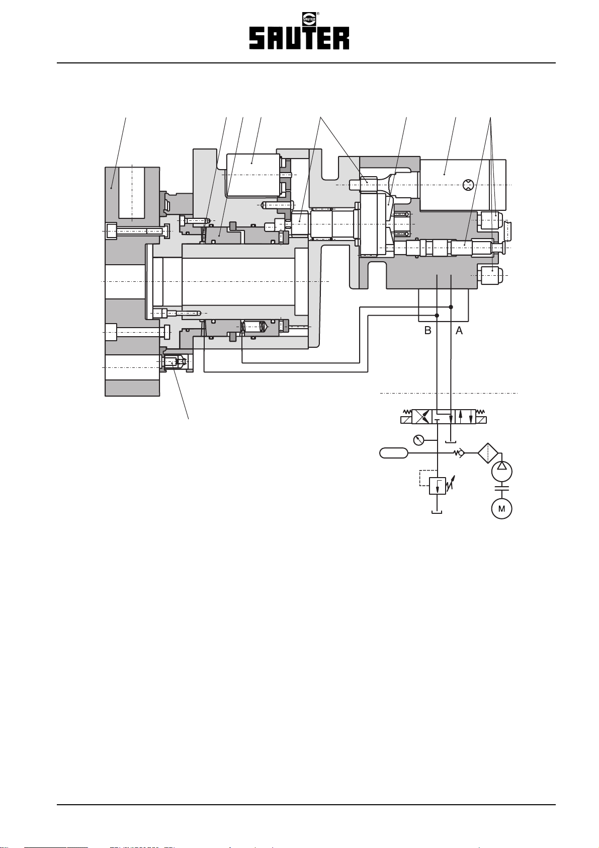
Turret series 0.5.680.1xx
Description
7
8
6
5
4
3
2
1
9
1 Control vaves
2 Hydraulic drive motor
3 Radial cam
4 Spur wheel gear
5 Electrical position transmitter
6 Locking piston
7 Hirth serration
8 Tool disk
9 Cooling lubricant valve
5PI 36.3 e
Page 6
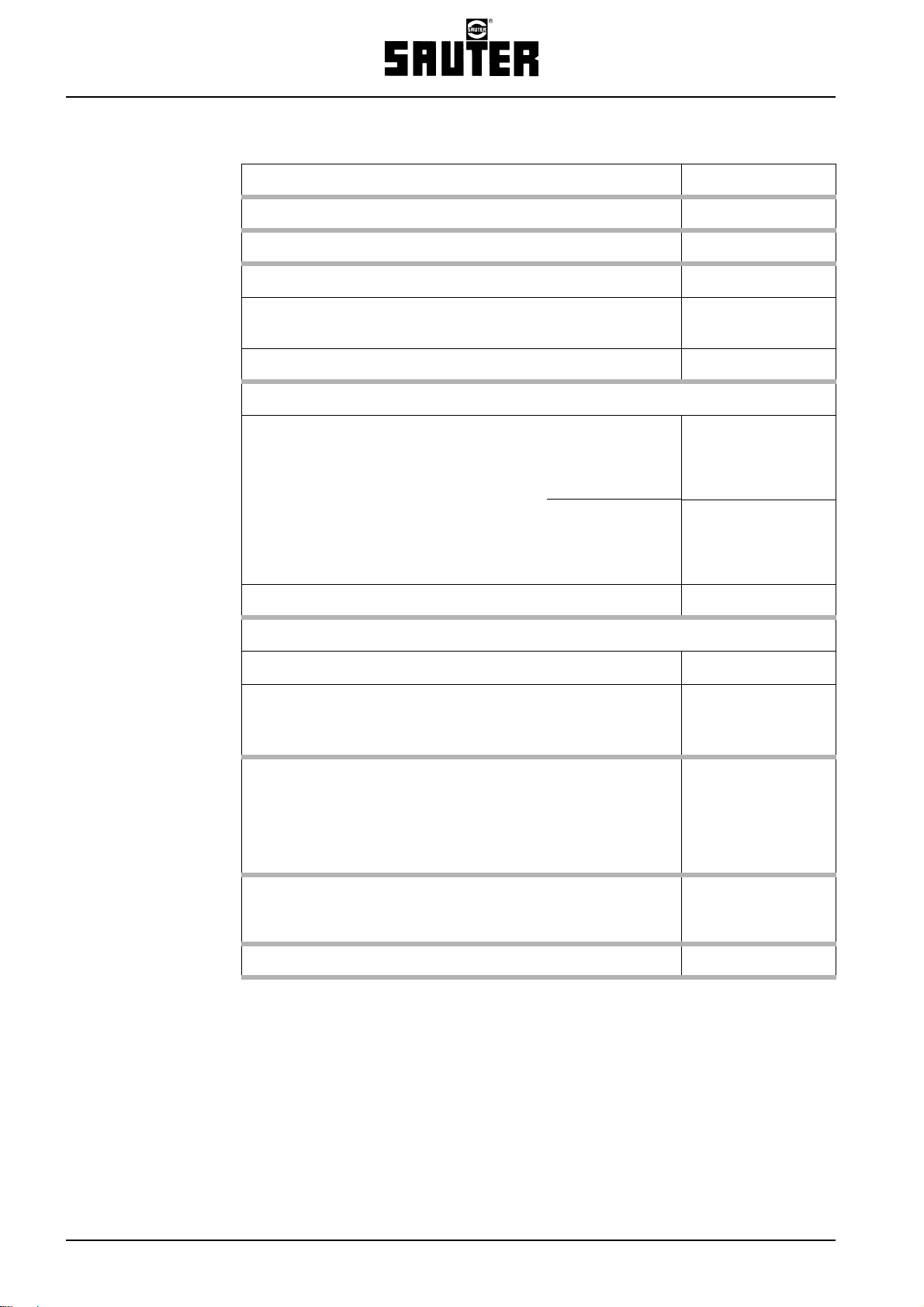
Turret series 0.5.680.1xx
Technical Data
Series
Disk-type tool turret 0.5.680.1xx
Number of switching positons
Admissible tangential load (locked turret) kNm
• Admissible mass moment of inertia of Standard load stage
tooling (tool disk and holder) High load load stage
kgm
kgm
Admissible unbalanced mass due to tooling Nm
Indexing times
1.)
Rotating tool disk
• Incl. accelerating and braking Standard load stage
per partial step 45°/30°/22.5° High load load stage
• Without accelerating and braking Standard load stage
per additional partial step 45°/30°/22.5° High load load stage
s
s
Turret unlockedor locked s
Adm. Indexing freqency (median switching angle ϕ
=90°) min
m
Operating pressure
Hydraulics ± 10 % bar
Cooling lubricant
• With medium pressure valve
2.)
• With central high pressure lubricant device
bar
bar
2
2
-1
Fluid absorption volume
• Rotating tool disk Standard load stage
per partial step 45°/30°/22.5° High load load stage
Turret unlocked or locked cm
Mass
Turret (incl. drive motor) m
Tool disk and tooling m
adm.
Adm. ambient temperature °C
1.) Conditions: Fluid supply has to be sufficiently dimensioned.
Please comply with notes in PA 36.3!
Turret has to be at operating temperature.
With max. unbalanced tooling, the rotation times are changed by max. ± 15%.
See planning instructions PA 36.3 for notes on determining the total switching time.
2.) Also suitable for min. cooling lubricant volumes when using special valve.
cm
cm
kg
kg
3
3
3
6 PI 36.3 e
Page 7
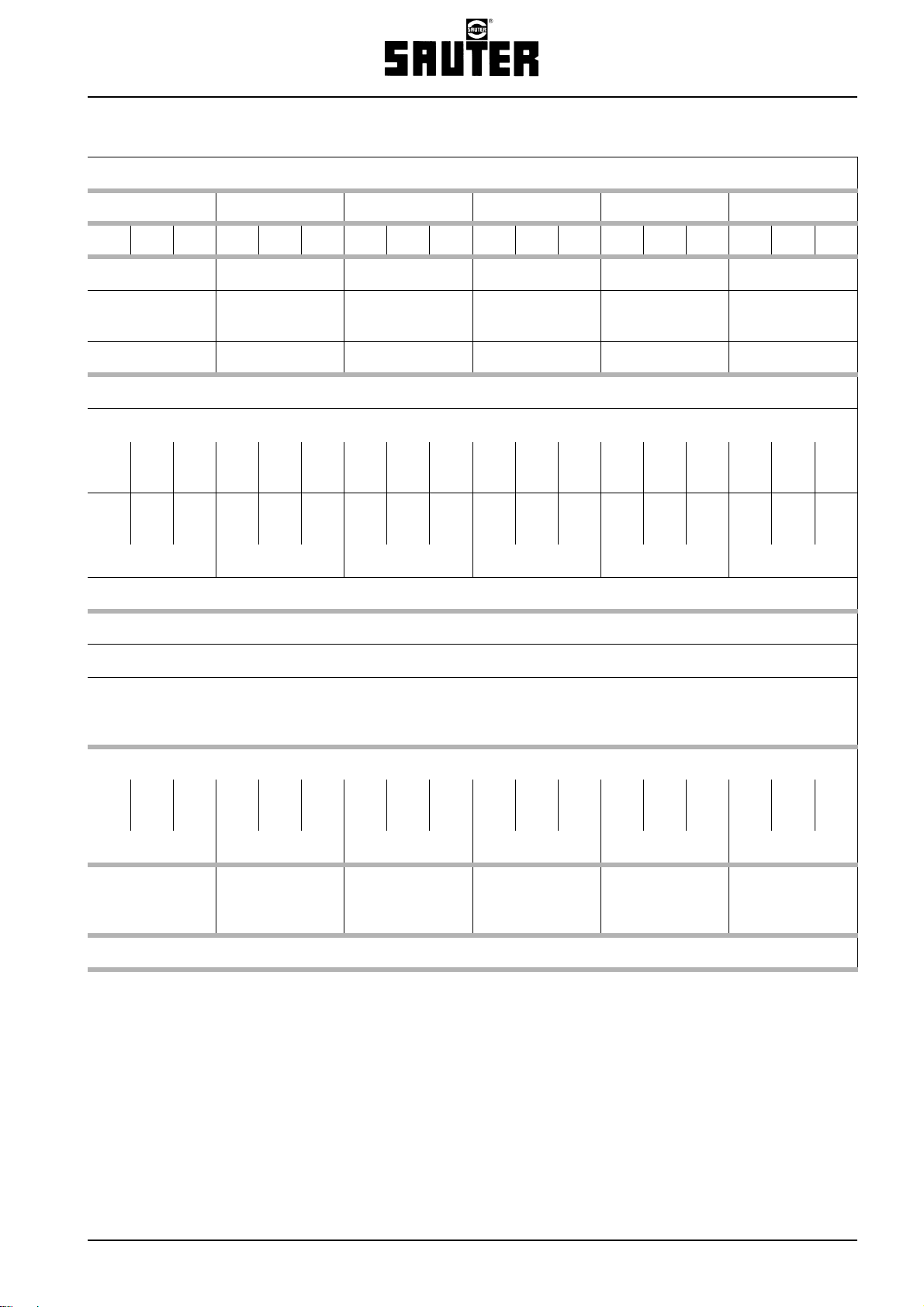
Turret series 0.5.680.1xx
Technical Data
Size
12 16 20 25 32 40
812168121681216812168
3.)
12
3.)
16 8
0.7 1.3 3.2 6.3 12.5 25
1.2
2.5
2.5
5.0
5.0
10
12.5
32
25
63 140
16 32 63 125 200 320
0.21
0.26
0.16
0.24
0.16
0.19–0.16
0.11
0.17–0.12
0.26
0.30
0.19
0.28
0.20
0.22–0.18
0.13
0.19–0.14
0.30
0.38
0.21
0.31
0.24
0.29–0.22
0.15
0.21–0.16
0.46
0.57
0.33
0.46
0.36
0.43
0.22
0.31
0.26
0.30
0.17
0.23
0.52
0.92
0.46
0.82
0.38
0.31
0.68
0.55 1.0 0.72 0.58
0.31
0.23
0.55
0.42 0.83 0.56 0.42
0.11 0.14 0.20 0.30 0.50 0.80
no limitations
50
3.)
12
3.)
16
5 .. 25 Filtering 100 µm
100 Filtering 25 µm
46753150–3746753150–3750803455–4081
12754854063
4.)
4.)
100
160681105080 254 170 127
12 28 42 65 114 165
38
40
50
80
70
160
110
250
190
400
10 ... 40
3.) Delivered with 24 switching positions.
4.) Comply with the fineness of the filter required for the utilised tools, e.g. spindle heads with internal cooling lubricant supply.
380
630
7PI 36.3 e
Page 8

Turret series 0.5.680.1xx
Admissible loads
Primary cutting force ±F
(turning forward)
(Fx, Fz)
y
Size 16
Size 12
Size 20
Size 25
Size 40
Size 32
Primary cutting force ±F
(turning backward)
Size 12
(Fx, Fz)
y
Size 16
Size 40
Size 32
Size 25
Size 20
Feed force +F
(drilling forward)
Size 12
z
Size 16
Size 20
Size 25
Size 40
Size 32
Feed force –F
z
Transverse force +F
Size 16
Size 12
x
Size 40
Size 32
Size 25
Size 20
Note: The diagrams apply to static loads.
Significantly lower values have to be used with shock loads (discontinous cutting).
8 PI 36.3 e
Page 9

Turret series 0.5.680.1xx
Dimensions
Turret geometry with
block form or fitted flange housing upon
request
Series Size
Disk-type tool
turret 0.5.680.1xx
12
16 20 25 32 40
right left
A 63 80 100 125 160 200
B 120 133 138T 153 182 226
C 175 215 255 318 396 470
D 80 65 85 100 125 160 200
E 65 80 85 100 125 160 200
Ø F 90 120 145 182 220 300
G 8 x M8 8 x M8 11 x M10 11 x M12 15 x M12 22 x M12
H 128 138 155 190 220 341
I M8 M10 M12 M16 M20 M24
K 324041526270
Ø L 70 90 110 120 150 200
M 385 428 460 508 550 670
N 192 192 210 262 312 442
O 85 100 106 125 158 198 245
P 100 85 106 125 158 198 245
Ø Q 175 215 255 318 396 470
Dimensions in mm
9PI 36.3 e
Page 10

Turret series 0.5.680.1xx
Precision/fluid rotary feed-through
Precision
Repeating accuracy
(Multiple move to a switching position from the same direction)
Indexing precision
(Multiple move to a switching position from different direction)
Fluid rotary feed-through
All turrets are deliverable with central fluid rotary feed-through:
• “Uncontrolled” variation – fluid supply in all switching positions,
e.g. for sealing air, for gripper activation, and similar actions
• “Controlled” variation – fluid supply to one switching position,
e.g. for KSS, autom. tool changes, and other functions
A maximum of three supply lines are routed through the centre of the turret.
Operating pressure P
= 100 bar (standard)
adm.
10 PI 36.3 e
Page 11

Axial tool drive
Description
Disk-type tool turret 0.5.673.xxx/0.5.676.xxx
with axial tool drive
These turrets feature a modular construction and consist of the following:
• Basic turret series 0.5.680.1xx and
• decentralised tool drive for
individually switchable axial tools
for forwardmachining.
The tool coupling can alternatively be supplied for spindle heads with or without the patented spindle locking system.
This means that the tools are either connected after positioning the drive spindle or after searching.
– When conducting search run with small – positioning with controls is not required
number of revolutions per minute electromagnetically activated coupling
or
– after positioning the drive spindle – shortest switching time
Hydraulically activated coupling
Suitable spindle heads
Coupling
process
with
Small number of
revolutions
Spindle positioning 0.5.676.2xx yes 0.5.941.xxx
Spur wheel
drive
turret
series
0.5.673.2xx no 0.5.921.xxx
Tool drive
motor
Spindle locking
system
spindle head type
SAUTER
Tool
disk
Tool
Sliding coupling
Coupling wheel
The tool drive motor drives the coupling wheel via the spur wheel gear incorporated in the gearbox casing. The drive
motor can be located at the side of the turret opposite the working position or above the turret casing, depending on the
application.
Basic turret
11PI 36.3 e
Page 12

Axial tool drive
Performance data/motor recommendation
Performance data for the tool coupling
The gearbox is designed for the performance data given below for the
tool coupling. The actually available performance data depend on the utilised
drive motor (see below).
Series
Disk-type tool turret 0.5.673.xxx/676.xxx
Gearbox performance data
Adm. drive rating
Adm. torque
Adm. rpm
Gear ratio
7.)
2.)
1.) 3.)
1.)
P
M
n
adm.
adm.
adm.
Nm
min
i
kW
-1
Recommended drive motors
Siemens servomotor,
Type 1 FT 6..
Max. torque
Max. rpm
Indramat servomotor,
Max. torque
Max. rpm
6.)
6.)
Type MKD..
6.)
6.)
4.)
Nm
min
Nm
min
-1
-1
Fanuc spindle motor, Type Alpha..
Max. torque
Max. rpm
1.) The values are reference values for short-term operation. Higher rpms generate more heat and noise.
2.) Torque limitation at motor converter required!
The listed torque values apply to smooth machining (such as thread-cutting).
In the case of machining with severe shock loads (e.g. face milling and similar operations), it is necessary
to reduce the motor drive torque by 50% or more.
3.) Higher rpms upon request.
4.) With absolute value encoder for turret series 0.5.676.xxx
5.) Spindle motor
6.) At tool coupling 40% WT – 10 min
7.) i = 1.5 only with turret series 0.5.676.xxx
6.)
6.)
Nm
min
-1
12 PI 36.3 e
Page 13

Axial tool drive
Performance data/Drive motors
Size
12 16 20 25 32 40
6
20
6000
8
32
5000
10
63
4000
12.5
100
4000
16
160
3200
16
160
3200
~1.5 1.0 1.0 ~1.5 1.0 ~1.5 1.0 ~1.5 1.0 ~1.5 1.0
..062
-AK..
12.5
4500
..064
-AK..
14
6000
..084
-AK..
28
5000
3000
..071 B ..090 B ..112 B
15
4000
14
6000
α 1.5
11
6000
22
5000
2600
α 2 α 3 α 6 α 8 α 8
25
5000
4000
..86 - AH..
58
60
55
40
4000
42
4000
40
4000
..102
-AH..
58
3200
2AD
100 C
78
4000
..105
1PH7
-AF
68
4000
5.)
..112C 2AD 100D..
68
4000
56
4000
-107..
125
3200
108
3200
5.)
120
3200
..105
-AF
68
3200
5.)
72
3200
5.)
1PH7
-107..
125
3200683200
2AD 100D..
108
3200723200
120
3200
Adm. relative working time – Reference values for gears –
..105
-AF..
5.)
Favourable
conditions
Adm. rpm
Unfavourable
conditions
Adm. drive rating
Working time WT – 10 min
Example for size 20:
Tool coupling = 3000 min
n
adm.
⇒ n
Tool coupling
= 4000 min
= 75% n
-1
-1
adm.
⇒ Working time 40% - 10 min (max. 4 min ON – min. 6 min OFF)
13PI 36.3 e
Page 14

Axial tool drive
Alternate configurations
Motor arrangement possible
in position 9°° or 12°°
Working
position
d
1
Tool arrangement:
(Depicted
turret arrangement "right”)
8 pos. – 1 graduated circle
12 pos. – 2 graduated circles 12 pos. – 1 graduated circle
16 pos. – 2 graduated circles 16 pos. – 1 graduated circle
14 PI 36.3 e
쏹 Position with tool drive
쎻 Position w/o tool drive
Page 15

Alternate configurations
Axial tool drive
Alternate configurations
Coupling profile
Turret
Size
12 +98.54 / -17
16 +117. 4 / -25
20 +155 / 0
25 +198 / -70
Working
position
X / Y
+100 / 0
+142.5 / 0
Motor
position
9°°
9°°
9°°
0.5.673.2xx 0.5.676.2xx
DIN 5480-
W10x0.8
+100/0 9°° –
9°°
+125 / -25
+135 / 0
+150 / 0
+150 / 0
+170 / 0
+185 / 0
9°°
12°°
9°°
12°°
9°°
9°°
9°°
DIN 5482-
DIN 5482-
9°°
+200 / 0
+200 / -20
+235 / -70
9°°
12°°
9°°
DIN 5482-
Turret series
15x12
17x14
20x17
DIN 5480-
W11x0.8
DIN 5480-
W14x0.8
DIN 5480-
W16x0.8
DIN 5480-
W20x0.8
DIN 5480W24x1.25
Tool holder
Receptacle
Ø
DIN 69880
d
1
20
20
20
25 12-2
30
30
30
30
30
40
40
40
50
50
50
50
Possible
tool
arrangement
see page 13
12-2
12-2
16-1
12-2
12-2
12-2
12-1
12-1
12-2
12-2
12-1
12-2
12-2
12-2
12-1
32 +265 / -80 12°°
40 +387.8 / -125 9°° 60 12- 1
DIN 5482-
25x22
–
60 12- 1
Bold print indicates quickest delivery!
Additional variations – e.g. variation “left” upon request.
15PI 36.3 e
Page 16

Radial tool drive
Description
Disk-type tool turret 0.5.675.1xx
with radial tool drive
These turrets consists of the following:
• Basic turret series 0.5.680.1xx and
• tool drive central
for individually switchable radial tools
for forward and backward machining.
The tool drive is intended for the spindle positioning. This requires spindle heads with spindle locking system
– Sauter spindle heads series 0.5.941.xx .
Tool drive motor
Geared head
Tool disk
Tool coupling
Belt drive
Central drive shaft
The tool drive motor drives the drive shaft, which is located centrally within the turret in a hollow shaft. The relevant tool
is switched into the working position by means of a bevel gear and a fluid-switched coupling in the gearbox head at the
front.
Coupling and decoupling of the spindle head located in the working position is executed after each positioning of the
drive spindle – not tooth-on-tooth situation, shortest switching time!
The tool disk is an integrated part of the turret with these turret systems.
16 PI 36.3 e
Page 17

Radial tool drive
Motor arrangement
Motor arrangement
The tool drive motor can be installed directly on the turret or with a belt drive, depending on the application specifications.
• Direct motor installation
• Motor installation with belt drive
Z – 9°° (left)
Z – 3°° (right)
U – 9°° (left)
U – 3°° (right)
17PI 36.3 e
Page 18

Radial tool drive
Performance data/Drive motors
Performance data for the tool coupling
The gearbox is designed for the performance data given below for the tool coupling.
The actually available performance data depend on the utilised drive motor (see below).
Series Size
Disk-type tool turret 0.5.675.1xx 12 16 20 25
Gearbox performance data
Adm. drive rating
Adm. torque
Adm. rpm
1.) 3.)
Gear ratio i = n
2.)
1.)
P
M
n
Adm.
Adm.
Adm.
1/n2
kW
Nm
min
6
-1
20
6000
8
32
5000
10
63
4000
12.5
100
4000
1.0 1.0 1.0 1.0
Recommended drive motors
Siemens servomotor,
Max. torque
Max. torque
5.)
5.)
Indramat servomotor,
Max. torque
Max. torque
5.)
5.)
Type 1 FT 6..
Type MKD..
4.)
Nm
min
Nm
min
..064-.AK.
-1
14
6000
..071B
-1
14
6000
.0.084-.AK.
28
5000
.0.090B
22
5000
..086-.AH.
40
4000
.0.112B
48
4000
..105-.AF..
68
4000
..112C
68
4000
Fanuc spindle motor,
Max. torque
Max. torque
1.) The values are reference values for short-term operation. Higher rpms generate more heat and noise, especially when the belt drive is
used!
2.) Torque limitation at motor converter required!
The listed torque values apply to smooth machining (such as thread-cutting). In the case of machining with severe shock loads (e.g. face
milling and similar operations), it is necessary to reduce the motor drive torque by 50% or more.
3.) Higher rpms upon request.
4.) With absolute value encoder.
5.) At tool coupling 40% WT – 10 min
5.)
5.)
Type Alpha..
Nm
min
-1
1.5
15
6000
2
25
5000
3
40
4000
6
56
4000
Adm. relative working time – Reference values for gears –
Favourable
conditions
Adm. rpm
Unfavourable
conditions
Adm. drive rating
Working time WT – 10 min
18 PI 36.3 e
Example for size 20:
Tool coupling = 3000 min
n
adm.
⇒ n
Tool coupling
= 4000 min
= 75% n
-1
-1
adm.
⇒ Working time 40% – 10 min
(max. 4 min ON – min. 6 min OFF)
Page 19

Radial tool drive
Selectable
working positions
12 o’clock
Dimensions
9 o’clock
3 o’clock
Series Size
Disk-type tool turret 0.5.675.1xx 12 16 20 25
Coupling profile DIN 5480 14 x 0.8 16 x 0.8 20 x 0.8 24 x 1.25
Distance A
dimension A
(standard)
1
(upon request)
2
–
80
K 324041 52
Tool holder receptacle system
Cylinder shaft DIN 69880
d
1
SW
standard 220 270 320 380
1
SW
2
SW
3
Tool system
Coromant Capto
2.)
1.)
25 30 40 50
240 360 410
300 340 380
NG C3 C4 C5
SW 280 340 380
1.) Use SAUTER spindle heads Type 0.5.941.xxx (product information PI 29.3)
2.) Use SAUTER spindle heads Type 0.5.934.xxx (product information PI 45)
Additional tool systems – e.g. HSK available upon request.
55
96
80
159
100
198
Dimensions in mm
19PI 36.3 e
Page 20

Type key
Type key
Turret series 0.5.680.xxx and 0.5.675.xxx
Example:
0.5.675.1xx
Size
12
16
0.5.680.120
.
25
32
40
12
16
0.5.675.120
25
Function/
configuration
Turret series 0.5.673.xxx and 0.5.676.xxx
Example:
0.5.676.2xx
Size
Function/
configuration
0.5.675.1 Hydraulically operated disk-type turret
0.5.680.1 Hydraulically operated disk-type turret
12
16
0.5.673.220
25
32
40
0.5.673.2 Hydraulically operated disk-type turret with single
with single radial tool drive
Tool coupling with spindle positioning
without tool drive
12
16
0.5.676.220
25
axial tool drive
Tool coupling with small number of revolutions per
minute
Electromagnetically activated tool coupling
0.5.676.2 Hydraulically operated disk-type turret
20 PI 36.3 e
with single axial tool drive
Tool coupling with spindle positioning
Hydraulically activated tool coupling
Page 21

Ordering details
Fax ++49 (0) 7123-926-190
@
SAUTER Disk-Type Tool Turret 0.5.680.1xx / 0.5.673.2xx / 0.5.676.2xx / 0.5.675.1xx
Ordering details Alternate configurations Your selection
Basic turret
++49 (0) 7123-926-0
info@sauter-gmbh.com
SAUTER Feinmechanik GmbH
Postfach 1551
D-72545 Metzingen
Germany
Size
Number of switching positions
Load stage
Housing shape/form
Installation position
Fluid rotary feed-through
Company:
Street:
ZIP/City:
Name:
Phone:
Fax:
12 / 16 / 20 / 25 / 32 / 40
8 / 12 / 16
Standard / high load
Standard /
Block/flange design
...........................
...........................
Axial tool drive
Working position X / Y
Motor position
Intended drive motor
Gear ratio
Coupling profile
Radial tool drive
Working position
Tool disk SW
Neck length A
Tool receptacle system
Drive motor arrangement
Intended drive motor
Electronic control unit
Special requirements/requests:
see page 14/15
3°° / 9°° / 12°°
see page 11/12
1.0 / ~1.5
see page 14/15
3°° / 9°° / 12°°
SW
/ SW2 / SW
1
A1 / A
DIN 69880 /Sandvik Capto
direct – U/Z – right / left
see page 18
EK 501
3
2
21PI 36.3 e
 Loading...